EP3595082A1 - Integrated device and manufacturing method thereof - Google Patents
Integrated device and manufacturing method thereof Download PDFInfo
- Publication number
- EP3595082A1 EP3595082A1 EP18182598.5A EP18182598A EP3595082A1 EP 3595082 A1 EP3595082 A1 EP 3595082A1 EP 18182598 A EP18182598 A EP 18182598A EP 3595082 A1 EP3595082 A1 EP 3595082A1
- Authority
- EP
- European Patent Office
- Prior art keywords
- waveguide
- integrated device
- separate
- manufacturing
- holes
- Prior art date
- Legal status (The legal status is an assumption and is not a legal conclusion. Google has not performed a legal analysis and makes no representation as to the accuracy of the status listed.)
- Granted
Links
Images




Classifications
-
- H—ELECTRICITY
- H01—ELECTRIC ELEMENTS
- H01Q—ANTENNAS, i.e. RADIO AERIALS
- H01Q13/00—Waveguide horns or mouths; Slot antennas; Leaky-waveguide antennas; Equivalent structures causing radiation along the transmission path of a guided wave
- H01Q13/02—Waveguide horns
- H01Q13/025—Multimode horn antennas; Horns using higher mode of propagation
- H01Q13/0258—Orthomode horns
-
- H—ELECTRICITY
- H01—ELECTRIC ELEMENTS
- H01P—WAVEGUIDES; RESONATORS, LINES, OR OTHER DEVICES OF THE WAVEGUIDE TYPE
- H01P1/00—Auxiliary devices
- H01P1/16—Auxiliary devices for mode selection, e.g. mode suppression or mode promotion; for mode conversion
- H01P1/161—Auxiliary devices for mode selection, e.g. mode suppression or mode promotion; for mode conversion sustaining two independent orthogonal modes, e.g. orthomode transducer
-
- H—ELECTRICITY
- H01—ELECTRIC ELEMENTS
- H01P—WAVEGUIDES; RESONATORS, LINES, OR OTHER DEVICES OF THE WAVEGUIDE TYPE
- H01P11/00—Apparatus or processes specially adapted for manufacturing waveguides or resonators, lines, or other devices of the waveguide type
- H01P11/001—Manufacturing waveguides or transmission lines of the waveguide type
- H01P11/002—Manufacturing hollow waveguides
-
- H—ELECTRICITY
- H01—ELECTRIC ELEMENTS
- H01Q—ANTENNAS, i.e. RADIO AERIALS
- H01Q1/00—Details of, or arrangements associated with, antennas
- H01Q1/50—Structural association of antennas with earthing switches, lead-in devices or lightning protectors
-
- H—ELECTRICITY
- H01—ELECTRIC ELEMENTS
- H01Q—ANTENNAS, i.e. RADIO AERIALS
- H01Q13/00—Waveguide horns or mouths; Slot antennas; Leaky-waveguide antennas; Equivalent structures causing radiation along the transmission path of a guided wave
- H01Q13/02—Waveguide horns
- H01Q13/0208—Corrugated horns
- H01Q13/0225—Corrugated horns of non-circular cross-section
-
- H—ELECTRICITY
- H01—ELECTRIC ELEMENTS
- H01Q—ANTENNAS, i.e. RADIO AERIALS
- H01Q13/00—Waveguide horns or mouths; Slot antennas; Leaky-waveguide antennas; Equivalent structures causing radiation along the transmission path of a guided wave
- H01Q13/02—Waveguide horns
- H01Q13/0241—Waveguide horns radiating a circularly polarised wave
-
- H—ELECTRICITY
- H01—ELECTRIC ELEMENTS
- H01Q—ANTENNAS, i.e. RADIO AERIALS
- H01Q13/00—Waveguide horns or mouths; Slot antennas; Leaky-waveguide antennas; Equivalent structures causing radiation along the transmission path of a guided wave
- H01Q13/02—Waveguide horns
- H01Q13/0283—Apparatus or processes specially provided for manufacturing horns
Definitions
- the invention relates to an integrated device, especially comprising a horn antenna, a waveguide transition element, and an orthomode transducer, and a corresponding manufacturing method thereof.
- KR 10 2015 0069792 A discloses a jig device for measuring the performance of a polarizer and, more specifically, a jig capable of measuring the performance of a polarizer changing a phase. Furthermore, the jig measures the performance of a polarizer outputting polarization, inputted through an input terminal of the polarizer, through an output terminal of the polarizer by changing the polarization into circular polarization.
- the jig includes an input terminal measuring jig receiving linear polarization having an inclined angle to spread the polarization to the input terminal of the polarizer, and an output terminal measuring jig separating the circular polarization, delivered from the output terminal, into horizontal polarization and vertical polarization to output the polarization to different output ports.
- said jig consists of many separate parts, its manufacturing is complex and expensive.
- an integrated device comprises a horn antenna with an antenna waveguide feed, a waveguide transition element comprising a first end connected to the antenna waveguide feed and a second end, and an orthomode transducer comprising a common waveguide connected to the second end of the waveguide transition element and at least two separate waveguides.
- the orthomode transducer is adapted to couple at least two orthogonal linear polarized fields into the common waveguide of the orthomode transducer with the aid of the at least two separate waveguides of the orthomode transducer and/or vice versa.
- the horn antenna is preferably adapted to support at least two waveguide modes corresponding to the at least two orthogonal linear polarized fields.
- the integrated device is preferably manufactured in at least two separate blocks such that each part of the at least two piece assembly is constructed as external protrusions and/or holes and/or partial holes.
- the antenna waveguide feed is an elliptical antenna waveguide feed, preferably a circular antenna waveguide feed.
- complexity can further be reduced.
- the first end of the waveguide transition element is of elliptical shape, preferably of circular shape.
- complexity can further be reduced.
- the second end of the waveguide transition element is of rectangular shape, preferably of square shape.
- complexity can further be reduced, thereby especially increasing cost-efficiency.
- the common waveguide of the orthomode transducer is of rectangular shape, preferably of square shape.
- cost-efficiency can further be increased especially by reducing complexity.
- At least one of the at least two separate waveguides of the orthomode transducer is of rectangular shape.
- a further reduced complexity can be ensured.
- alignment pins and threaded holes are provided on the at least two piece assembly to facilitate the assembly.
- an accurate and efficient assembly can be guaranteed.
- the integrated device further comprises at least one waveguide to coax interface, preferably at least one rectangular waveguide to coax interface.
- the at least one waveguide to coax interface preferably the at least one rectangular waveguide to coax interface, is connected to at least one of the at least two separate waveguides of the orthomode transducer.
- a coaxial transmission line or a coaxial cable can efficiently be connected.
- the at least one waveguide to coax interface preferably the at least one rectangular waveguide to coax interface, is constructed as a separate and/or detachable part.
- complexity can further be reduced.
- the integrated device comprises at least one screw connection for connecting the at least two separate blocks.
- assembling can be performed in a cost-efficient manner.
- At least one of the at least two separate blocks comprises metal, preferably metal comprising a gold plating, more preferably aluminium, most preferably aluminium comprising a gold plating, and/or graphene, preferably a graphene plating.
- metal preferably metal comprising a gold plating, more preferably aluminium, most preferably aluminium comprising a gold plating, and/or graphene, preferably a graphene plating.
- waveguide modes can be guided with a high quality.
- the integrated device is manufactured in three separate blocks such that each part of the three piece assembly is constructed as external protrusions and/or partial holes.
- the external protrusions and/or partial holes are milled without forming enclosed internal cavities and/or holes.
- cost-efficiency can further be increased.
- a manufacturing method for manufacturing an integrated device comprising a horn antenna, a waveguide transition element, and an orthomode transducer.
- the manufacturing method comprises the steps of manufacturing the integrated device in at least two separate blocks, and constructing each part of the at least two piece assembly as external protrusions and/or holes and/or partial holes.
- a reduced complexity and a high cost-efficiency can be ensured.
- the manufacturing method further comprises the step of providing alignment pins and threaded holes on the at least two piece assembly to facilitate the assembly.
- the step of providing alignment pins and threaded holes on the at least two piece assembly to facilitate the assembly.
- the manufacturing method further comprises the steps of manufacturing the integrated device in three separate blocks, constructing each part of the three piece assembly as external protrusions and/or partial holes, and milling the external protrusions and/or partial holes without forming enclosed internal cavities and/or holes.
- cost-efficiency can further be increased.
- Fig. 1 illustrates a first exemplary embodiment of an inventive integrated device 10.
- the integrated device 10 comprises a horn antenna 31 with an antenna waveguide feed 32, a waveguide transition element 33 comprising a first end connected to the antenna waveguide feed and a second end, and an orthomode transducer comprising a common waveguide 34 connected to the second end of the waveguide transition element and two separate waveguides, especially a first separate waveguide 35 and a second separate waveguide 36.
- the orthomode transducer is adapted to couple at least two orthogonal linear polarized fields into the common waveguide 34 of the orthomode transducer with the aid of the two separate waveguides 35, 36 of the orthomode transducer and/or vice versa, wherein the horn antenna 31 is adapted to support at least two waveguide modes corresponding to the at least two orthogonal linear polarized fields.
- the integrated device or integrated part 10 is manufactured in three separate blocks 11, 12, 13 such that each part of the three piece assembly is constructed as external protrusions and/or partial holes, wherein the external protrusions and/or partial holes are especially milled without forming enclosed internal cavities and/or holes.
- the antenna waveguide feed 32 is a circular antenna waveguide feed
- the common waveguide 34 of the orthomode transducer is of square shape.
- the first end of the waveguide transition element 33 is of circular shape, whereas the second end of the waveguide transition element 33 is of square shape.
- the wave guide transition element 33 is a circular to square waveguide transition element.
- each of the two separate waveguides 35, 36 of the orthomode transducer is of rectangular shape.
- Fig. 1 depicts that the integrated device 10 further comprises two waveguide to coax interfaces, preferably two rectangular waveguide to coax interfaces, especially a first rectangular waveguide to coax interface 37 and a second rectangular waveguide to coax interface 38.
- each of the two rectangular waveguide to coax interfaces 37, 38 is connected to the respective one of the two separate waveguides 35, 36 of the orthomode transducer.
- each of the two rectangular waveguide to coax interfaces 37, 38 may be constructed as a separate and/or detachable part.
- the integrated device or part 10 may preferably comprise at least one screw connection for connecting the three separate blocks 11, 12, 13.
- At least one of the three separate blocks 11, 12, 13 may especially comprise metal, preferably metal comprising a gold plating, more preferably aluminium, most preferably aluminium comprising a gold plating, and/or graphene, preferably a graphene plating.
- Fig. 2 illustrates the bottom part 11 of the first exemplary embodiment according to Fig. 1 .
- the second separate waveguide 36 is divided into two partial waveguides, especially a first partial waveguide 361 and a second partial waveguide 362.
- the respective pathways of the first partial waveguide 361 and the second partial waveguide 362 are symmetric with respect to an axis, especially a longitudinal axis, of the second separate waveguide 36. It might be particularly advantageous if said axis, especially said longitudinal axis, runs through the center of the second separate waveguide 36.
- At least one, exemplarily each, of the partial waveguides 361, 362 is of a curved shape, a parabolic shape, or an U-shape.
- the common waveguide 34 and the second separate waveguide 36 are especially comprised, preferably intersected or touched, by the same plane.
- the first separate waveguide 35 is preferably perpendicularly arranged with respect to the common waveguide 34 and/or the second separate waveguide 36.
- the region 39 is bevelled.
- the respective surface rises with decreasing distance from the common waveguide 34 or from the horn antenna 31, respectively.
- the respective surface falls with decreasing distance from the horn antenna 31.
- said exemplary bottom part 11 comprises a part of the horn antenna 31, a part of the antenna waveguide feed 32, a part of the waveguide transition element 33, a part of the common waveguide 34, a part of the first partial waveguide 361, a part of the second partial waveguide 362, a part of the second separate waveguide 36, and a part of the second rectangular waveguide to coax interface 38.
- the first top part 12 of the first embodiment 10 comprises a part of the horn antenna 31, a part of the antenna waveguide feed 32, a part of the waveguide transition element 33, a part of the common waveguide 34, a part of the first partial waveguide 361, a part of the second partial waveguide 362, and a part of the first separate waveguide 35.
- the second top part 13 of the first embodiment 10 comprises a part of the first partial waveguide 361, a part of the second partial waveguide 362, a part of the first separate waveguide 35, a part of the second separate waveguide 36, the first rectangular waveguide to coax interface 37, and a part of the second rectangular waveguide to coax interface 38.
- the integrated device 20 comprises a horn antenna 41 with an antenna waveguide feed 42, a waveguide transition element 43 comprising a first end connected to the antenna waveguide feed 42 and a second end, and an orthomode transducer comprising a common waveguide 44 connected to the second end of the waveguide transition element 43 and two separate waveguides, especially a first separate waveguide 45 and a second separate waveguide 46.
- the orthomode transducer is adapted to couple at least two orthogonal linear polarized fields into the common waveguide 44 of the orthomode transducer with the aid of the two separate waveguides 45, 46 of the orthomode transducer and/or vice versa, wherein the horn antenna 41 is adapted to support at least two waveguide modes corresponding to the at least two orthogonal linear polarized fields.
- the integrated device 20 is manufactured in two separate blocks 21, 22 such that each part of the two piece assembly is constructed as external protrusions and/or and/or holes and/or partial holes.
- the antenna waveguide feed 42 is a circular antenna waveguide feed
- the common waveguide 44 of the orthomode transducer is of square shape.
- the first end of the waveguide transition element 43 is of circular shape, whereas the second end of the waveguide transition element 43 is of square shape.
- the wave guide transition element 43 is a circular to square waveguide transition element.
- each of the two separate waveguides 35, 36 of the orthomode transducer is of rectangular shape.
- Fig. 5 illustrates that the integrated device 20 further comprises two waveguide to coax interfaces, preferably two rectangular waveguide to coax interfaces, especially a first rectangular waveguide to coax interface 47 and a second rectangular waveguide to coax interface 48.
- each of the two rectangular waveguide to coax interfaces 47, 48 is connected to the respective one of the two separate waveguides 45, 46 of the orthomode transducer.
- each of the two rectangular waveguide to coax interfaces 47, 48 may be constructed as a separate and/or detachable part.
- the integrated device 20 may preferably comprise at least one screw connection for connecting the two separate blocks 21, 22.
- At least one of the two separate blocks 21, 22 may especially comprise metal, preferably metal comprising a gold plating, more preferably aluminium, most preferably aluminium comprising a gold plating, and/or graphene, preferably a graphene plating.
- Fig. 6 illustrates the bottom part 21 of the second exemplary embodiment according to Fig. 5 .
- the second separate waveguide 46 is divided into two partial waveguides, especially a first partial waveguide 461 and a second partial waveguide 462.
- the respective pathways of the first partial waveguide 461 and the second partial waveguide 462 are symmetric with respect to an axis, especially a longitudinal axis, of the second separate waveguide 46. It might be particularly advantageous if said axis, especially said longitudinal axis, runs through the center of the second separate waveguide 46.
- At least one, exemplarily each, of the partial waveguides 461, 462 is of a curved shape, a parabolic shape, or an U-shape.
- the common waveguide 44 and the second separate waveguide 46 are especially comprised, preferably intersected or touched, by the same plane.
- the first separate waveguide 45 is preferably perpendicularly arranged with respect to the common waveguide 44 and/or the second separate waveguide 46.
- the region 49 is bevelled.
- the respective surface rises with decreasing distance from the common waveguide 44 or from the horn antenna 41, respectively.
- the respective surface falls with decreasing distance from the horn antenna 41.
- said exemplary bottom part 21 comprises a part of the horn antenna 41, a part of the antenna waveguide feed 42, a part of the waveguide transition element 43, a part of the common waveguide 44, a part of the first partial waveguide 461, a part of the second partial waveguide 462, a part of the second separate waveguide 46, and a part of the second rectangular waveguide to coax interface 48.
- the top part 22 of the second embodiment 20 comprises a part of the horn antenna 41, a part of the antenna waveguide feed 42, a part of the waveguide transition element 43, a part of the common waveguide 44, the first separate waveguide 45, a part of the first partial waveguide 461, a part of the second partial waveguide 462, a part of the second separate waveguide 46, the first rectangular waveguide to coax interface 47, and a part of the second rectangular waveguide to coax interface 48.
- Fig. 8 shows a flow chart of an exemplary embodiment of the inventive manufacturing method.
- a first step 100 an integrated device comprising a horn antenna, a waveguide transition element, and an orthomode transducer is manufactured in at least two separate blocks.
- each part of the at least two piece assembly is constructed as external protrusions and/or holes and/or partial holes.
- the antenna waveguide feed is manufactured as an elliptical antenna waveguide feed, preferably a circular antenna waveguide feed.
- the first end of the waveguide transition element may especially be of elliptical shape, preferably of circular shape.
- the second end of the waveguide transition element may especially be of rectangular shape, preferably of square shape.
- the common waveguide of the orthomode transducer may especially be of rectangular shape, preferably of square shape.
- At least one of the at least two separate waveguides of the orthomode transducer may preferably be of rectangular shape.
- the manufacturing method further comprises the step of providing alignment pins and threaded holes on the at least two piece assembly to facilitate the assembly.
- the manufacturing method may further comprise the steps of providing at least one waveguide to coax interface, preferably at least one rectangular waveguide to coax interface, for the integrated device, and connecting the at least one waveguide to coax interface, preferably the at least one rectangular waveguide to coax interface, to at least one of the at least two separate waveguides of the orthomode transducer.
- the manufacturing method may further comprise the step of constructing the at least one waveguide to coax interface, preferably the at least one rectangular waveguide to coax interface, as a separate and/or detachable part.
- the manufacturing method may further comprise the step of connecting the at least two separate blocks of the integrated device with the aid of at least one screw connection.
- At least one of the at least two separate blocks may especially comprise metal, preferably metal comprising a gold plating, more preferably aluminium, most preferably aluminium comprising a gold plating, and/or graphene, preferably a graphene plating.
- the manufacturing method comprises the steps of manufacturing the integrated device in three separate blocks, constructing each part of the three piece assembly as external protrusions and/or partial holes, and milling the external protrusions and/or partial holes without forming enclosed internal cavities and/or holes.
Landscapes
- Engineering & Computer Science (AREA)
- Manufacturing & Machinery (AREA)
- Waveguide Aerials (AREA)
Abstract
Description
- The invention relates to an integrated device, especially comprising a horn antenna, a waveguide transition element, and an orthomode transducer, and a corresponding manufacturing method thereof.
- Generally, in times of an increasing number of applications providing wireless communication capabilites, there is a growing need of a cost-efficient integrated device and a corresponding manufacturing method thereof for efficiently transmitting and/or receiving signals with respect to said applications in order to verify a proper functioning thereof.
-
KR 10 2015 0069792 A - There is the object to provide a cost-efficient integrated device and a corresponding manufacturing method thereof.
- This object is solved by the features of claim 1 for a cost-efficient integrated device and the features of
claim 13 for the corresponding manufacturing method. The dependent claims contain further developments. - According to a first aspect of the invention, an integrated device is provided. The integrated device comprises a horn antenna with an antenna waveguide feed, a waveguide transition element comprising a first end connected to the antenna waveguide feed and a second end, and an orthomode transducer comprising a common waveguide connected to the second end of the waveguide transition element and at least two separate waveguides. In this context, the orthomode transducer is adapted to couple at least two orthogonal linear polarized fields into the common waveguide of the orthomode transducer with the aid of the at least two separate waveguides of the orthomode transducer and/or vice versa.
- In addition to this, the horn antenna is preferably adapted to support at least two waveguide modes corresponding to the at least two orthogonal linear polarized fields. Furthermore, the integrated device is preferably manufactured in at least two separate blocks such that each part of the at least two piece assembly is constructed as external protrusions and/or holes and/or partial holes. Advantageously, in this manner, a reduced complexity and a high cost-efficiency can be ensured.
- According to a further preferred implementation form of the first aspect of the invention, the antenna waveguide feed is an elliptical antenna waveguide feed, preferably a circular antenna waveguide feed. Advantageously, for instance, complexity can further be reduced.
- According to a further preferred implementation form of the first aspect of the invention, the first end of the waveguide transition element is of elliptical shape, preferably of circular shape. Advantageously, for example, complexity can further be reduced.
- According to a further preferred implementation form of the first aspect of the invention, the second end of the waveguide transition element is of rectangular shape, preferably of square shape. Advantageously, for instance, complexity can further be reduced, thereby especially increasing cost-efficiency.
- According to a further preferred implementation form of the first aspect of the invention, the common waveguide of the orthomode transducer is of rectangular shape, preferably of square shape. Advantageously, for example, cost-efficiency can further be increased especially by reducing complexity.
- According to a further preferred implementation form of the first aspect of the invention, at least one of the at least two separate waveguides of the orthomode transducer is of rectangular shape. Advantageously, for instance, a further reduced complexity can be ensured.
- According to a further preferred implementation form of the first aspect of the invention, alignment pins and threaded holes are provided on the at least two piece assembly to facilitate the assembly. Advantageously, in this manner, an accurate and efficient assembly can be guaranteed.
- According to a further preferred implementation form of the first aspect of the invention, the integrated device further comprises at least one waveguide to coax interface, preferably at least one rectangular waveguide to coax interface. In this context, the at least one waveguide to coax interface, preferably the at least one rectangular waveguide to coax interface, is connected to at least one of the at least two separate waveguides of the orthomode transducer. Advantageously, a coaxial transmission line or a coaxial cable can efficiently be connected.
- According to a further preferred implementation form of the first aspect of the invention, the at least one waveguide to coax interface, preferably the at least one rectangular waveguide to coax interface, is constructed as a separate and/or detachable part. Advantageously, for instance, complexity can further be reduced.
- According to a further preferred implementation form of the first aspect of the invention, the integrated device comprises at least one screw connection for connecting the at least two separate blocks. Advantageously, assembling can be performed in a cost-efficient manner.
- According to a further preferred implementation form of the first aspect of the invention, at least one of the at least two separate blocks comprises metal, preferably metal comprising a gold plating, more preferably aluminium, most preferably aluminium comprising a gold plating, and/or graphene, preferably a graphene plating. Advantageously, waveguide modes can be guided with a high quality.
- According to a further preferred implementation form of the first aspect of the invention, the integrated device is manufactured in three separate blocks such that each part of the three piece assembly is constructed as external protrusions and/or partial holes. In this context, the external protrusions and/or partial holes are milled without forming enclosed internal cavities and/or holes. Advantageously, especially due to an easy milling process, cost-efficiency can further be increased.
- According to a second aspect of the invention, a manufacturing method for manufacturing an integrated device comprising a horn antenna, a waveguide transition element, and an orthomode transducer is provided. The manufacturing method comprises the steps of manufacturing the integrated device in at least two separate blocks, and constructing each part of the at least two piece assembly as external protrusions and/or holes and/or partial holes. Advantageously, in this manner, a reduced complexity and a high cost-efficiency can be ensured.
- According to a first preferred implementation form of the second aspect of the invention, the manufacturing method further comprises the step of providing alignment pins and threaded holes on the at least two piece assembly to facilitate the assembly. Advantageously, in this manner, an accurate and efficient assembly can be guaranteed.
- According to a further preferred implementation form of the second aspect of the invention, the manufacturing method further comprises the steps of manufacturing the integrated device in three separate blocks, constructing each part of the three piece assembly as external protrusions and/or partial holes, and milling the external protrusions and/or partial holes without forming enclosed internal cavities and/or holes. Advantageously, especially due to an easy milling process, cost-efficiency can further be increased.
- Exemplary embodiments of the invention are now further explained with respect to the drawings by way of example only, and not for limitation. In the drawings:
- Fig. 1
- shows a first exemplary embodiment of the first aspect of the invention based on a three piece assembly;
- Fig. 2
- shows the bottom part of the first exemplary embodiment;
- Fig. 3
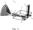
- shows the first top part of the first exemplary embodiment;
- Fig. 4
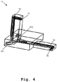
- shows the second top part of the first exemplary embodiment;
- Fig. 5
- shows a second exemplary embodiment of the inventive integrated device based on a two piece assembly;
- Fig. 6
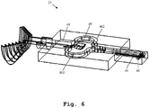
- shows the bottom part of the second exemplary embodiment;
- Fig. 7
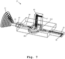
- shows the top part of the second exemplary embodiment; and
- Fig. 8
- shows a flow chart of an exemplary embodiment of the second aspect of the invention.
- Firstly,
Fig. 1 illustrates a first exemplary embodiment of an inventive integrateddevice 10. Theintegrated device 10 comprises ahorn antenna 31 with anantenna waveguide feed 32, awaveguide transition element 33 comprising a first end connected to the antenna waveguide feed and a second end, and an orthomode transducer comprising acommon waveguide 34 connected to the second end of the waveguide transition element and two separate waveguides, especially a firstseparate waveguide 35 and a secondseparate waveguide 36. - In this context, the orthomode transducer is adapted to couple at least two orthogonal linear polarized fields into the
common waveguide 34 of the orthomode transducer with the aid of the twoseparate waveguides horn antenna 31 is adapted to support at least two waveguide modes corresponding to the at least two orthogonal linear polarized fields. - As it can further be seen from
Fig. 1 , the integrated device orintegrated part 10 is manufactured in threeseparate blocks - Furthermore, it is noted that the
antenna waveguide feed 32 is a circular antenna waveguide feed, whereas thecommon waveguide 34 of the orthomode transducer is of square shape. - As a consequence of this, the first end of the
waveguide transition element 33 is of circular shape, whereas the second end of thewaveguide transition element 33 is of square shape. In other words, in this exemplary case, the waveguide transition element 33 is a circular to square waveguide transition element. - Moreover, according to
Fig. 1 , each of the twoseparate waveguides - It is noted that it might be particularly advantageous if alignment pins and threaded holes are provided on the three
piece assembly 10 in order to facilitate the assembly. - Whereas said alignment pins and threaded holes are not explicitly shown in
Fig. 1, Fig. 1 depicts that theintegrated device 10 further comprises two waveguide to coax interfaces, preferably two rectangular waveguide to coax interfaces, especially a first rectangular waveguide to coaxinterface 37 and a second rectangular waveguide to coaxinterface 38. - In this context, each of the two rectangular waveguide to coax
interfaces separate waveguides - Preferably, each of the two rectangular waveguide to coax
interfaces - Furthermore, it is noted that the integrated device or
part 10 may preferably comprise at least one screw connection for connecting the threeseparate blocks - It is further noted that at least one of the three
separate blocks - Moreover,
Fig. 2 illustrates thebottom part 11 of the first exemplary embodiment according toFig. 1 . As it can be seen, before the waves guided by the firstseparate waveguide 35 and the secondseparate waveguide 36 enter thecommon waveguide 34 of the orthomode transducer, the secondseparate waveguide 36 is divided into two partial waveguides, especially a firstpartial waveguide 361 and a secondpartial waveguide 362. - In this context, it is noted that the respective pathways of the first
partial waveguide 361 and the secondpartial waveguide 362 are symmetric with respect to an axis, especially a longitudinal axis, of the secondseparate waveguide 36. It might be particularly advantageous if said axis, especially said longitudinal axis, runs through the center of the secondseparate waveguide 36. - Furthermore, it might be particularly advantageous if at least one, exemplarily each, of the
partial waveguides - With special respect to the orthomode transducer comprising the
common waveguide 34, the firstseparate waveguide 35, and the secondseparate waveguide 36, it is noted that thecommon waveguide 34 and the secondseparate waveguide 36 are especially comprised, preferably intersected or touched, by the same plane. In addition to this, the firstseparate waveguide 35 is preferably perpendicularly arranged with respect to thecommon waveguide 34 and/or the secondseparate waveguide 36. - Moreover, in accordance with
Fig. 2 , the region 39, especially being located near thecommon waveguide 34 and in which the firstseparate waveguide 35 is arranged, is bevelled. Preferably, the respective surface rises with decreasing distance from thecommon waveguide 34 or from thehorn antenna 31, respectively. In addition to this or as an alternative, especially within thecommon waveguide 34 or within an entry area of thecommon waveguide 34, the respective surface falls with decreasing distance from thehorn antenna 31. - Furthermore, with respect to the
bottom part 11 illustrated byFig. 2 , it is noted that said exemplarybottom part 11 comprises a part of thehorn antenna 31, a part of theantenna waveguide feed 32, a part of thewaveguide transition element 33, a part of thecommon waveguide 34, a part of the firstpartial waveguide 361, a part of the secondpartial waveguide 362, a part of the secondseparate waveguide 36, and a part of the second rectangular waveguide to coaxinterface 38. - In addition to this, as shown in
Fig. 3 , the firsttop part 12 of thefirst embodiment 10 comprises a part of thehorn antenna 31, a part of theantenna waveguide feed 32, a part of thewaveguide transition element 33, a part of thecommon waveguide 34, a part of the firstpartial waveguide 361, a part of the secondpartial waveguide 362, and a part of the firstseparate waveguide 35. - Further additionally, in accordance with
Fig. 4 , the secondtop part 13 of thefirst embodiment 10 comprises a part of the firstpartial waveguide 361, a part of the secondpartial waveguide 362, a part of the firstseparate waveguide 35, a part of the secondseparate waveguide 36, the first rectangular waveguide to coaxinterface 37, and a part of the second rectangular waveguide to coaxinterface 38. - Now, with respect to
Fig. 5 , a second exemplary embodiment of an inventiveintegrated device 20 is depicted. Theintegrated device 20 comprises ahorn antenna 41 with anantenna waveguide feed 42, awaveguide transition element 43 comprising a first end connected to theantenna waveguide feed 42 and a second end, and an orthomode transducer comprising acommon waveguide 44 connected to the second end of thewaveguide transition element 43 and two separate waveguides, especially a firstseparate waveguide 45 and a secondseparate waveguide 46. - In this context, the orthomode transducer is adapted to couple at least two orthogonal linear polarized fields into the
common waveguide 44 of the orthomode transducer with the aid of the twoseparate waveguides horn antenna 41 is adapted to support at least two waveguide modes corresponding to the at least two orthogonal linear polarized fields. - As it can further be seen from
Fig. 5 , theintegrated device 20 is manufactured in twoseparate blocks - Furthermore, it is noted that the
antenna waveguide feed 42 is a circular antenna waveguide feed, whereas thecommon waveguide 44 of the orthomode transducer is of square shape. - As a consequence of this, the first end of the
waveguide transition element 43 is of circular shape, whereas the second end of thewaveguide transition element 43 is of square shape. In other words, in this exemplary case, the waveguide transition element 43 is a circular to square waveguide transition element. - Moreover, according to
Fig. 5 , each of the twoseparate waveguides - It is noted that it might be particularly advantageous if alignment pins and threaded holes are provided on the two
piece assembly 20 in order to facilitate the assembly. - Whereas said alignment pins and threaded holes are not explicitly shown in
Fig. 5, Fig. 5 illustrates that theintegrated device 20 further comprises two waveguide to coax interfaces, preferably two rectangular waveguide to coax interfaces, especially a first rectangular waveguide to coaxinterface 47 and a second rectangular waveguide to coaxinterface 48. - In this context, each of the two rectangular waveguide to coax
interfaces separate waveguides - Preferably, each of the two rectangular waveguide to coax
interfaces - Furthermore, it is noted that the
integrated device 20 may preferably comprise at least one screw connection for connecting the twoseparate blocks - It is further noted that at least one of the two
separate blocks - Moreover,
Fig. 6 illustrates thebottom part 21 of the second exemplary embodiment according toFig. 5 . As it can be seen, before the waves guided by the firstseparate waveguide 45 and the secondseparate waveguide 46 enter thecommon waveguide 44 of the orthomode transducer, the secondseparate waveguide 46 is divided into two partial waveguides, especially a firstpartial waveguide 461 and a secondpartial waveguide 462. - In this context, it is noted that the respective pathways of the first
partial waveguide 461 and the secondpartial waveguide 462 are symmetric with respect to an axis, especially a longitudinal axis, of the secondseparate waveguide 46. It might be particularly advantageous if said axis, especially said longitudinal axis, runs through the center of the secondseparate waveguide 46. - Furthermore, it might be particularly advantageous if at least one, exemplarily each, of the
partial waveguides - With special respect to the orthomode transducer comprising the
common waveguide 44, the firstseparate waveguide 45, and the secondseparate waveguide 46, it is noted that thecommon waveguide 44 and the secondseparate waveguide 46 are especially comprised, preferably intersected or touched, by the same plane. In addition to this, the firstseparate waveguide 45 is preferably perpendicularly arranged with respect to thecommon waveguide 44 and/or the secondseparate waveguide 46. - Moreover, in accordance with
Fig. 6 , theregion 49, especially being located near thecommon waveguide 44 and in which the firstseparate waveguide 45 is arranged, is bevelled. Preferably, the respective surface rises with decreasing distance from thecommon waveguide 44 or from thehorn antenna 41, respectively. In addition to this or as an alternative, especially within thecommon waveguide 44 or within an entry area of thecommon waveguide 44, the respective surface falls with decreasing distance from thehorn antenna 41. - Furthermore, with respect to the
bottom part 21 illustrated byFig. 6 , it is noted that said exemplarybottom part 21 comprises a part of thehorn antenna 41, a part of theantenna waveguide feed 42, a part of thewaveguide transition element 43, a part of thecommon waveguide 44, a part of the firstpartial waveguide 461, a part of the secondpartial waveguide 462, a part of the secondseparate waveguide 46, and a part of the second rectangular waveguide to coaxinterface 48. - In addition to this, as illustrated by
Fig. 7 , thetop part 22 of thesecond embodiment 20 comprises a part of thehorn antenna 41, a part of theantenna waveguide feed 42, a part of thewaveguide transition element 43, a part of thecommon waveguide 44, the firstseparate waveguide 45, a part of the firstpartial waveguide 461, a part of the secondpartial waveguide 462, a part of the secondseparate waveguide 46, the first rectangular waveguide to coaxinterface 47, and a part of the second rectangular waveguide to coaxinterface 48. - In this context, it is noted that it might be particularly advantageous if said part is especially a half.
- Finally,
Fig. 8 shows a flow chart of an exemplary embodiment of the inventive manufacturing method. In afirst step 100, an integrated device comprising a horn antenna, a waveguide transition element, and an orthomode transducer is manufactured in at least two separate blocks. Then, in asecond step 101, each part of the at least two piece assembly is constructed as external protrusions and/or holes and/or partial holes. - In this context, it might be particularly advantageous if the antenna waveguide feed is manufactured as an elliptical antenna waveguide feed, preferably a circular antenna waveguide feed.
- Further advantageously, the first end of the waveguide transition element may especially be of elliptical shape, preferably of circular shape.
- In addition to this or as an alternative, the second end of the waveguide transition element may especially be of rectangular shape, preferably of square shape.
- Further additionally or alternatively, the common waveguide of the orthomode transducer may especially be of rectangular shape, preferably of square shape.
- Furthermore, it is noted that at least one of the at least two separate waveguides of the orthomode transducer may preferably be of rectangular shape.
- Moreover, it might be particularly advantageous if the manufacturing method further comprises the step of providing alignment pins and threaded holes on the at least two piece assembly to facilitate the assembly.
- In addition to this or as an alternative, the manufacturing method may further comprise the steps of providing at least one waveguide to coax interface, preferably at least one rectangular waveguide to coax interface, for the integrated device, and connecting the at least one waveguide to coax interface, preferably the at least one rectangular waveguide to coax interface, to at least one of the at least two separate waveguides of the orthomode transducer.
- In this context, the manufacturing method may further comprise the step of constructing the at least one waveguide to coax interface, preferably the at least one rectangular waveguide to coax interface, as a separate and/or detachable part.
- Additionally or alternatively, the manufacturing method may further comprise the step of connecting the at least two separate blocks of the integrated device with the aid of at least one screw connection.
- In further addition to this or as a further alternative, at least one of the at least two separate blocks may especially comprise metal, preferably metal comprising a gold plating, more preferably aluminium, most preferably aluminium comprising a gold plating, and/or graphene, preferably a graphene plating.
- Furthermore, it is noted that it might be particularly advantageous if the manufacturing method comprises the steps of manufacturing the integrated device in three separate blocks, constructing each part of the three piece assembly as external protrusions and/or partial holes, and milling the external protrusions and/or partial holes without forming enclosed internal cavities and/or holes.
- While various embodiments of the present invention have been described above, it should be understood that they have been presented by way of example only, and not limitation. Numerous changes to the disclosed embodiments can be made in accordance with the disclosure herein without departing from the spirit or scope of the invention. For example, a current may be measured instead of a voltage. Thus, the breadth and scope of the present invention should not be limited by any of the above-described embodiments. Rather, the scope of the invention should be defined in accordance with the following claims and their equivalents.
- Although the invention has been illustrated and described with respect to one or more implementations, equivalent alterations and modifications will occur to others skilled in the art upon the reading and understanding of this specification and the annexed drawings. In addition, while a particular feature of the invention may have been disclosed with respect to only one of several implementations, such feature may be combined with one or more other features of the other implementations as may be desired and advantageous for any given or particular application.
Claims (15)
- An integrated device (10, 20) comprising:a horn antenna (31, 41) with an antenna waveguide feed (32, 42),a waveguide transition element (33, 43) comprising a first end connected to the antenna waveguide (32, 42) feed and a second end, andan orthomode transducer comprising a common waveguide connected (34, 44) to the second end of the waveguide transition element (33, 43) and at least two separate waveguides (35, 36, 45, 46),wherein the orthomode transducer is adapted to couple at least two orthogonal linear polarized fields into the common waveguide (34, 44) of the orthomode transducer with the aid of the at least two separate waveguides (35, 36, 45, 46) of the orthomode transducer and/or vice versa.
- The integrated device according to claim 1,
wherein the horn antenna (31, 41) is adapted to support at least two waveguide modes corresponding to the at least two orthogonal linear polarized fields, and/or
wherein the integrated device (10, 20) is manufactured in at least two separate blocks (11, 12, 13, 21, 22) such that each part of the at least two piece assembly is constructed as external protrusions and/or holes and/or partial holes. - The integrated device (10, 20) according to claim 1 or 2,
wherein the antenna waveguide feed (32, 42) is an elliptical antenna waveguide feed, preferably a circular antenna waveguide feed, and/or
wherein the first end of the waveguide transition element (33, 43) is of elliptical shape, preferably of circular shape. - The integrated (10, 20) device according to any of the claims 1 to 3,
wherein the second end of the waveguide transition element (33, 43) is of rectangular shape, preferably of square shape. - The integrated device (10, 20) according to any of the claims 1 to 4,
wherein the common waveguide (34, 44) of the orthomode transducer is of rectangular shape, preferably of square shape. - The integrated device (10, 20) according to any of the claims 1 to 5,
wherein at least one of the at least two separate waveguides (35, 36, 45, 46) of the orthomode transducer is of rectangular shape. - The integrated device (10, 20) according to any of the claims 1 to 6,
wherein alignment pins and threaded holes are provided on the at least two piece assembly to facilitate the assembly. - The integrated device (10, 20) according to any of the claims 1 to 7,
wherein the integrated device (10, 20) further comprises at least one waveguide to coax interface (37, 38, 47, 48), preferably at least one rectangular waveguide to coax interface,
wherein the at least one waveguide to coax interface (37, 38, 47, 48), preferably the at least one rectangular waveguide to coax interface, is connected to at least one of the at least two separate waveguides (35, 36, 45, 46) of the orthomode transducer. - The integrated device (10, 20) according to claim 8,
wherein the at least one waveguide to coax interface (37, 38, 47, 48), preferably the at least one rectangular waveguide to coax interface, is constructed as a separate and/or detachable part. - The integrated device (10, 20) according to any of the claims 1 to 9,
wherein the integrated device (10, 20) comprises at least one screw connection for connecting the at least two separate blocks (11, 12, 13, 21, 22). - The integrated device (10, 20) according to any of the claims 1 to 10,
wherein at least one of the at least two separate blocks (11, 12, 13, 21, 22) comprises metal, preferably metal comprising a gold plating, more preferably aluminium, most preferably aluminium comprising a gold plating, and/or graphene, preferably a graphene plating. - The integrated device (10, 20) according to any of the claims 1 to 11,
wherein the integrated device (10, 20) is manufactured in three separate blocks (11, 12, 13) such that each part of the three piece assembly is provided as external protrusions and/or partial holes, and
wherein the external protrusions and/or partial holes are milled without forming enclosed internal cavities and/or holes. - A manufacturing method for manufacturing an integrated device (10, 20) comprising a horn antenna (31, 41), a waveguide transition element (33, 43), and an orthomode transducer, the manufacturing method comprising the steps of:manufacturing the integrated device (10, 20) in at least two separate blocks (11, 12, 13, 21, 22), andmanufacturing each part of the at least two piece assembly as external protrusions and/or holes and/or partial holes.
- The manufacturing method according to claim 13, wherein the manufacturing method further comprises the step of providing alignment pins and threaded holes on the at least two piece assembly to facilitate the assembly.
- The manufacturing method according to claim 13 or 14, wherein the manufacturing method further comprises the steps of:manufacturing the integrated device (10, 20) in three separate blocks (11, 12, 13),constructing each part of the three piece assembly as external protrusions and/or partial holes, andmilling the external protrusions and/or partial holes without forming enclosed internal cavities and/or holes.
Priority Applications (3)
| Application Number | Priority Date | Filing Date | Title |
|---|---|---|---|
| EP18182598.5A EP3595082B8 (en) | 2018-07-10 | 2018-07-10 | Integrated device and manufacturing method thereof |
| US16/159,256 US10790591B2 (en) | 2018-07-10 | 2018-10-12 | Integrated device and manufacturing method thereof |
| CN201811583825.5A CN110707429B (en) | 2018-07-10 | 2018-12-24 | Integrated device and method of manufacturing the same |
Applications Claiming Priority (1)
| Application Number | Priority Date | Filing Date | Title |
|---|---|---|---|
| EP18182598.5A EP3595082B8 (en) | 2018-07-10 | 2018-07-10 | Integrated device and manufacturing method thereof |
Publications (3)
| Publication Number | Publication Date |
|---|---|
| EP3595082A1 true EP3595082A1 (en) | 2020-01-15 |
| EP3595082B1 EP3595082B1 (en) | 2020-09-02 |
| EP3595082B8 EP3595082B8 (en) | 2020-11-04 |
Family
ID=62909412
Family Applications (1)
| Application Number | Title | Priority Date | Filing Date |
|---|---|---|---|
| EP18182598.5A Active EP3595082B8 (en) | 2018-07-10 | 2018-07-10 | Integrated device and manufacturing method thereof |
Country Status (3)
| Country | Link |
|---|---|
| US (1) | US10790591B2 (en) |
| EP (1) | EP3595082B8 (en) |
| CN (1) | CN110707429B (en) |
Families Citing this family (4)
| Publication number | Priority date | Publication date | Assignee | Title |
|---|---|---|---|---|
| CN111900513B (en) * | 2020-09-04 | 2021-11-19 | 北京邮电大学 | Orthogonal mode converter, antenna device and communication system |
| US12040522B2 (en) * | 2021-10-19 | 2024-07-16 | Rohde & Schwarz Gmbh & Co. Kg | Over-the-air measurement system |
| US12407980B2 (en) | 2023-03-01 | 2025-09-02 | Qsc, Llc | Customizable waveguides and associated systems and methods |
| CN116885450B (en) * | 2023-07-26 | 2024-07-09 | 北京星英联微波科技有限责任公司 | Multi-polarization horn antenna with strong electromagnetic pulse protection function |
Citations (7)
| Publication number | Priority date | Publication date | Assignee | Title |
|---|---|---|---|---|
| US4047128A (en) * | 1975-04-19 | 1977-09-06 | Licentia Patent-Verwaltungs-G.M.B.H. | System filter for double frequency utilization |
| US4498062A (en) * | 1982-03-25 | 1985-02-05 | Sip - Societa Italiana Per L'esercizio Telefonico P.A. | Waveguide structure for separating microwaves with mutually orthogonal planes of polarization |
| US5617108A (en) * | 1994-03-21 | 1997-04-01 | Hughes Electronics | Simplified tracking antenna |
| US5784033A (en) * | 1996-06-07 | 1998-07-21 | Hughes Electronics Corporation | Plural frequency antenna feed |
| US20100141543A1 (en) * | 2008-11-11 | 2010-06-10 | Viasat, Inc. | Molded orthomode transducer |
| US20100207702A1 (en) * | 2007-09-07 | 2010-08-19 | Thales | OMT Type Broadband Multiband Transmission-Reception Coupler-Separator for RF Frequency Telecommunications Antennas |
| KR20150069792A (en) | 2013-12-16 | 2015-06-24 | 삼성탈레스 주식회사 | JIG for measuring performance polarizer |
Family Cites Families (8)
| Publication number | Priority date | Publication date | Assignee | Title |
|---|---|---|---|---|
| US6842085B2 (en) * | 2003-02-18 | 2005-01-11 | Victory Microwave Corporation | Orthomode transducer having improved cross-polarization suppression and method of manufacture |
| US7236681B2 (en) * | 2003-09-25 | 2007-06-26 | Prodelin Corporation | Feed assembly for multi-beam antenna with non-circular reflector, and such an assembly that is field-switchable between linear and circular polarization modes |
| GB2434923A (en) * | 2006-02-03 | 2007-08-08 | Ericsson Telefon Ab L M | Antenna feed device using two separate L-shaped waveguides to give an overall T-shape |
| GB2434922A (en) * | 2006-02-03 | 2007-08-08 | Ericsson Telefon Ab L M | Ortho-mode transducer connecting two rectangular waveguides to a common circular waveguide |
| US8013687B2 (en) * | 2008-04-04 | 2011-09-06 | Optim Microwave, Inc. | Ortho-mode transducer with TEM probe for coaxial waveguide |
| CN101694903B (en) * | 2009-10-22 | 2012-09-26 | 西安空间无线电技术研究所 | Dual-arm coupling quadrature mode coupler with high cross polarization discrimination |
| CN203871471U (en) * | 2014-04-30 | 2014-10-08 | 北京航天控制仪器研究所 | Filtering-based Ku/Ka dual-mode antenna feed source |
| CN105119055B (en) * | 2015-07-28 | 2017-11-07 | 西安空间无线电技术研究所 | A kind of V-band TE21 moulds track feed |
-
2018
- 2018-07-10 EP EP18182598.5A patent/EP3595082B8/en active Active
- 2018-10-12 US US16/159,256 patent/US10790591B2/en active Active
- 2018-12-24 CN CN201811583825.5A patent/CN110707429B/en active Active
Patent Citations (7)
| Publication number | Priority date | Publication date | Assignee | Title |
|---|---|---|---|---|
| US4047128A (en) * | 1975-04-19 | 1977-09-06 | Licentia Patent-Verwaltungs-G.M.B.H. | System filter for double frequency utilization |
| US4498062A (en) * | 1982-03-25 | 1985-02-05 | Sip - Societa Italiana Per L'esercizio Telefonico P.A. | Waveguide structure for separating microwaves with mutually orthogonal planes of polarization |
| US5617108A (en) * | 1994-03-21 | 1997-04-01 | Hughes Electronics | Simplified tracking antenna |
| US5784033A (en) * | 1996-06-07 | 1998-07-21 | Hughes Electronics Corporation | Plural frequency antenna feed |
| US20100207702A1 (en) * | 2007-09-07 | 2010-08-19 | Thales | OMT Type Broadband Multiband Transmission-Reception Coupler-Separator for RF Frequency Telecommunications Antennas |
| US20100141543A1 (en) * | 2008-11-11 | 2010-06-10 | Viasat, Inc. | Molded orthomode transducer |
| KR20150069792A (en) | 2013-12-16 | 2015-06-24 | 삼성탈레스 주식회사 | JIG for measuring performance polarizer |
Also Published As
| Publication number | Publication date |
|---|---|
| EP3595082B8 (en) | 2020-11-04 |
| CN110707429B (en) | 2023-04-18 |
| US10790591B2 (en) | 2020-09-29 |
| US20200021033A1 (en) | 2020-01-16 |
| CN110707429A (en) | 2020-01-17 |
| EP3595082B1 (en) | 2020-09-02 |
Similar Documents
| Publication | Publication Date | Title |
|---|---|---|
| EP3595082B1 (en) | Integrated device and manufacturing method thereof | |
| US10205213B2 (en) | Antenna formed from plates and methods useful in conjunction therewith | |
| US9000861B2 (en) | Polarization coupler | |
| CN111211394A (en) | Coaxial-waveguide converter array, antenna array and method for manufacturing waveguide device | |
| US9214711B2 (en) | Twist septum polarization rotator | |
| EP3618172B1 (en) | Antenna device and array antenna device | |
| EP2941795A1 (en) | Radio frequency power combiner | |
| JP2014007456A (en) | Coaxial waveguide converter and manufacturing method therefor | |
| US20180048043A1 (en) | Radio frequency filter having cavity structure | |
| JP2007228223A (en) | Waveguide connection | |
| CN109616721B (en) | Miniaturized circular polarizer | |
| US10700405B2 (en) | Integrated waveguide monopulse comparator assembly | |
| US11742560B2 (en) | T-junction with high isolation and method for fabricating the same | |
| JP2015070607A (en) | Inner-tube with opposing shallow-cavities for use in coaxial polarizer | |
| Rosenberg et al. | Combined twist-bend for very compact inter-connections in integrated waveguide subsystems | |
| JP2013207391A (en) | Connection structure of rectangular waveguide | |
| KR101549125B1 (en) | JIG for measuring performance polarizer | |
| JP4502967B2 (en) | Polarization converter | |
| CN104092002B (en) | H face cruciform power splitter | |
| CN219917828U (en) | Radio frequency coaxial phase modulation device | |
| US12170393B2 (en) | Polarizer for a waveguide and system for the transmission of high-frequency electromagnetic signals | |
| KR100845232B1 (en) | Circular Polarizer Having Oval Aperture and Feed Horn using that | |
| KR20190000563A (en) | Cavity filter | |
| KR20100079358A (en) | Phase adjustment device for use in radio frequency transmission lines | |
| JP5802300B1 (en) | Waveguide connection mechanism |
Legal Events
| Date | Code | Title | Description |
|---|---|---|---|
| PUAI | Public reference made under article 153(3) epc to a published international application that has entered the european phase |
Free format text: ORIGINAL CODE: 0009012 |
|
| STAA | Information on the status of an ep patent application or granted ep patent |
Free format text: STATUS: REQUEST FOR EXAMINATION WAS MADE |
|
| 17P | Request for examination filed |
Effective date: 20190121 |
|
| AK | Designated contracting states |
Kind code of ref document: A1 Designated state(s): AL AT BE BG CH CY CZ DE DK EE ES FI FR GB GR HR HU IE IS IT LI LT LU LV MC MK MT NL NO PL PT RO RS SE SI SK SM TR |
|
| AX | Request for extension of the european patent |
Extension state: BA ME |
|
| REG | Reference to a national code |
Ref country code: DE Ref legal event code: R079 Ref document number: 602018007409 Country of ref document: DE Free format text: PREVIOUS MAIN CLASS: H01P0001161000 Ipc: H01Q0013020000 |
|
| GRAP | Despatch of communication of intention to grant a patent |
Free format text: ORIGINAL CODE: EPIDOSNIGR1 |
|
| STAA | Information on the status of an ep patent application or granted ep patent |
Free format text: STATUS: GRANT OF PATENT IS INTENDED |
|
| RIC1 | Information provided on ipc code assigned before grant |
Ipc: H01P 11/00 20060101ALI20200401BHEP Ipc: H01P 1/161 20060101ALI20200401BHEP Ipc: H01Q 13/02 20060101AFI20200401BHEP |
|
| INTG | Intention to grant announced |
Effective date: 20200415 |
|
| GRAS | Grant fee paid |
Free format text: ORIGINAL CODE: EPIDOSNIGR3 |
|
| GRAA | (expected) grant |
Free format text: ORIGINAL CODE: 0009210 |
|
| STAA | Information on the status of an ep patent application or granted ep patent |
Free format text: STATUS: THE PATENT HAS BEEN GRANTED |
|
| AK | Designated contracting states |
Kind code of ref document: B1 Designated state(s): AL AT BE BG CH CY CZ DE DK EE ES FI FR GB GR HR HU IE IS IT LI LT LU LV MC MK MT NL NO PL PT RO RS SE SI SK SM TR |
|
| REG | Reference to a national code |
Ref country code: GB Ref legal event code: FG4D |
|
| REG | Reference to a national code |
Ref country code: AT Ref legal event code: REF Ref document number: 1309877 Country of ref document: AT Kind code of ref document: T Effective date: 20200915 Ref country code: CH Ref legal event code: EP |
|
| REG | Reference to a national code |
Ref country code: DE Ref legal event code: R096 Ref document number: 602018007409 Country of ref document: DE |
|
| RBV | Designated contracting states (corrected) |
Designated state(s): AL AT BE BG CY CZ DE DK EE ES FI FR GB GR HR HU IS IT LT LU LV MC MK MT NL NO PL PT RO RS SE SI SK SM TR |
|
| REG | Reference to a national code |
Ref country code: IE Ref legal event code: FG4D |
|
| REG | Reference to a national code |
Ref country code: LT Ref legal event code: MG4D |
|
| PG25 | Lapsed in a contracting state [announced via postgrant information from national office to epo] |
Ref country code: FI Free format text: LAPSE BECAUSE OF FAILURE TO SUBMIT A TRANSLATION OF THE DESCRIPTION OR TO PAY THE FEE WITHIN THE PRESCRIBED TIME-LIMIT Effective date: 20200902 Ref country code: LT Free format text: LAPSE BECAUSE OF FAILURE TO SUBMIT A TRANSLATION OF THE DESCRIPTION OR TO PAY THE FEE WITHIN THE PRESCRIBED TIME-LIMIT Effective date: 20200902 Ref country code: HR Free format text: LAPSE BECAUSE OF FAILURE TO SUBMIT A TRANSLATION OF THE DESCRIPTION OR TO PAY THE FEE WITHIN THE PRESCRIBED TIME-LIMIT Effective date: 20200902 Ref country code: GR Free format text: LAPSE BECAUSE OF FAILURE TO SUBMIT A TRANSLATION OF THE DESCRIPTION OR TO PAY THE FEE WITHIN THE PRESCRIBED TIME-LIMIT Effective date: 20201203 Ref country code: NO Free format text: LAPSE BECAUSE OF FAILURE TO SUBMIT A TRANSLATION OF THE DESCRIPTION OR TO PAY THE FEE WITHIN THE PRESCRIBED TIME-LIMIT Effective date: 20201202 Ref country code: BG Free format text: LAPSE BECAUSE OF FAILURE TO SUBMIT A TRANSLATION OF THE DESCRIPTION OR TO PAY THE FEE WITHIN THE PRESCRIBED TIME-LIMIT Effective date: 20201202 Ref country code: SE Free format text: LAPSE BECAUSE OF FAILURE TO SUBMIT A TRANSLATION OF THE DESCRIPTION OR TO PAY THE FEE WITHIN THE PRESCRIBED TIME-LIMIT Effective date: 20200902 |
|
| REG | Reference to a national code |
Ref country code: NL Ref legal event code: MP Effective date: 20200902 |
|
| REG | Reference to a national code |
Ref country code: AT Ref legal event code: MK05 Ref document number: 1309877 Country of ref document: AT Kind code of ref document: T Effective date: 20200902 |
|
| PG25 | Lapsed in a contracting state [announced via postgrant information from national office to epo] |
Ref country code: PL Free format text: LAPSE BECAUSE OF FAILURE TO SUBMIT A TRANSLATION OF THE DESCRIPTION OR TO PAY THE FEE WITHIN THE PRESCRIBED TIME-LIMIT Effective date: 20200902 Ref country code: RS Free format text: LAPSE BECAUSE OF FAILURE TO SUBMIT A TRANSLATION OF THE DESCRIPTION OR TO PAY THE FEE WITHIN THE PRESCRIBED TIME-LIMIT Effective date: 20200902 Ref country code: LV Free format text: LAPSE BECAUSE OF FAILURE TO SUBMIT A TRANSLATION OF THE DESCRIPTION OR TO PAY THE FEE WITHIN THE PRESCRIBED TIME-LIMIT Effective date: 20200902 |
|
| PG25 | Lapsed in a contracting state [announced via postgrant information from national office to epo] |
Ref country code: SM Free format text: LAPSE BECAUSE OF FAILURE TO SUBMIT A TRANSLATION OF THE DESCRIPTION OR TO PAY THE FEE WITHIN THE PRESCRIBED TIME-LIMIT Effective date: 20200902 Ref country code: EE Free format text: LAPSE BECAUSE OF FAILURE TO SUBMIT A TRANSLATION OF THE DESCRIPTION OR TO PAY THE FEE WITHIN THE PRESCRIBED TIME-LIMIT Effective date: 20200902 Ref country code: PT Free format text: LAPSE BECAUSE OF FAILURE TO SUBMIT A TRANSLATION OF THE DESCRIPTION OR TO PAY THE FEE WITHIN THE PRESCRIBED TIME-LIMIT Effective date: 20210104 Ref country code: RO Free format text: LAPSE BECAUSE OF FAILURE TO SUBMIT A TRANSLATION OF THE DESCRIPTION OR TO PAY THE FEE WITHIN THE PRESCRIBED TIME-LIMIT Effective date: 20200902 Ref country code: CZ Free format text: LAPSE BECAUSE OF FAILURE TO SUBMIT A TRANSLATION OF THE DESCRIPTION OR TO PAY THE FEE WITHIN THE PRESCRIBED TIME-LIMIT Effective date: 20200902 |
|
| PG25 | Lapsed in a contracting state [announced via postgrant information from national office to epo] |
Ref country code: ES Free format text: LAPSE BECAUSE OF FAILURE TO SUBMIT A TRANSLATION OF THE DESCRIPTION OR TO PAY THE FEE WITHIN THE PRESCRIBED TIME-LIMIT Effective date: 20200902 Ref country code: AL Free format text: LAPSE BECAUSE OF FAILURE TO SUBMIT A TRANSLATION OF THE DESCRIPTION OR TO PAY THE FEE WITHIN THE PRESCRIBED TIME-LIMIT Effective date: 20200902 Ref country code: AT Free format text: LAPSE BECAUSE OF FAILURE TO SUBMIT A TRANSLATION OF THE DESCRIPTION OR TO PAY THE FEE WITHIN THE PRESCRIBED TIME-LIMIT Effective date: 20200902 Ref country code: IS Free format text: LAPSE BECAUSE OF FAILURE TO SUBMIT A TRANSLATION OF THE DESCRIPTION OR TO PAY THE FEE WITHIN THE PRESCRIBED TIME-LIMIT Effective date: 20210102 |
|
| REG | Reference to a national code |
Ref country code: DE Ref legal event code: R097 Ref document number: 602018007409 Country of ref document: DE |
|
| PG25 | Lapsed in a contracting state [announced via postgrant information from national office to epo] |
Ref country code: SK Free format text: LAPSE BECAUSE OF FAILURE TO SUBMIT A TRANSLATION OF THE DESCRIPTION OR TO PAY THE FEE WITHIN THE PRESCRIBED TIME-LIMIT Effective date: 20200902 |
|
| PLBE | No opposition filed within time limit |
Free format text: ORIGINAL CODE: 0009261 |
|
| STAA | Information on the status of an ep patent application or granted ep patent |
Free format text: STATUS: NO OPPOSITION FILED WITHIN TIME LIMIT |
|
| 26N | No opposition filed |
Effective date: 20210603 |
|
| PG25 | Lapsed in a contracting state [announced via postgrant information from national office to epo] |
Ref country code: DK Free format text: LAPSE BECAUSE OF FAILURE TO SUBMIT A TRANSLATION OF THE DESCRIPTION OR TO PAY THE FEE WITHIN THE PRESCRIBED TIME-LIMIT Effective date: 20200902 |
|
| PG25 | Lapsed in a contracting state [announced via postgrant information from national office to epo] |
Ref country code: IT Free format text: LAPSE BECAUSE OF FAILURE TO SUBMIT A TRANSLATION OF THE DESCRIPTION OR TO PAY THE FEE WITHIN THE PRESCRIBED TIME-LIMIT Effective date: 20200902 |
|
| PG25 | Lapsed in a contracting state [announced via postgrant information from national office to epo] |
Ref country code: MC Free format text: LAPSE BECAUSE OF FAILURE TO SUBMIT A TRANSLATION OF THE DESCRIPTION OR TO PAY THE FEE WITHIN THE PRESCRIBED TIME-LIMIT Effective date: 20200902 |
|
| REG | Reference to a national code |
Ref country code: BE Ref legal event code: MM Effective date: 20210731 |
|
| PG25 | Lapsed in a contracting state [announced via postgrant information from national office to epo] |
Ref country code: LU Free format text: LAPSE BECAUSE OF NON-PAYMENT OF DUE FEES Effective date: 20210710 |
|
| PG25 | Lapsed in a contracting state [announced via postgrant information from national office to epo] |
Ref country code: BE Free format text: LAPSE BECAUSE OF NON-PAYMENT OF DUE FEES Effective date: 20210731 |
|
| PG25 | Lapsed in a contracting state [announced via postgrant information from national office to epo] |
Ref country code: NL Free format text: LAPSE BECAUSE OF NON-PAYMENT OF DUE FEES Effective date: 20200923 Ref country code: CY Free format text: LAPSE BECAUSE OF FAILURE TO SUBMIT A TRANSLATION OF THE DESCRIPTION OR TO PAY THE FEE WITHIN THE PRESCRIBED TIME-LIMIT Effective date: 20200902 |
|
| P01 | Opt-out of the competence of the unified patent court (upc) registered |
Effective date: 20230525 |
|
| PG25 | Lapsed in a contracting state [announced via postgrant information from national office to epo] |
Ref country code: HU Free format text: LAPSE BECAUSE OF FAILURE TO SUBMIT A TRANSLATION OF THE DESCRIPTION OR TO PAY THE FEE WITHIN THE PRESCRIBED TIME-LIMIT; INVALID AB INITIO Effective date: 20180710 |
|
| PG25 | Lapsed in a contracting state [announced via postgrant information from national office to epo] |
Ref country code: SI Free format text: LAPSE BECAUSE OF FAILURE TO SUBMIT A TRANSLATION OF THE DESCRIPTION OR TO PAY THE FEE WITHIN THE PRESCRIBED TIME-LIMIT Effective date: 20200902 |
|
| PG25 | Lapsed in a contracting state [announced via postgrant information from national office to epo] |
Ref country code: MK Free format text: LAPSE BECAUSE OF FAILURE TO SUBMIT A TRANSLATION OF THE DESCRIPTION OR TO PAY THE FEE WITHIN THE PRESCRIBED TIME-LIMIT Effective date: 20200902 |
|
| PG25 | Lapsed in a contracting state [announced via postgrant information from national office to epo] |
Ref country code: MT Free format text: LAPSE BECAUSE OF FAILURE TO SUBMIT A TRANSLATION OF THE DESCRIPTION OR TO PAY THE FEE WITHIN THE PRESCRIBED TIME-LIMIT Effective date: 20200902 |
|
| PGFP | Annual fee paid to national office [announced via postgrant information from national office to epo] |
Ref country code: DE Payment date: 20250722 Year of fee payment: 8 |
|
| PGFP | Annual fee paid to national office [announced via postgrant information from national office to epo] |
Ref country code: GB Payment date: 20250724 Year of fee payment: 8 |
|
| PGFP | Annual fee paid to national office [announced via postgrant information from national office to epo] |
Ref country code: FR Payment date: 20250723 Year of fee payment: 8 |
|
| PG25 | Lapsed in a contracting state [announced via postgrant information from national office to epo] |
Ref country code: TR Free format text: LAPSE BECAUSE OF FAILURE TO SUBMIT A TRANSLATION OF THE DESCRIPTION OR TO PAY THE FEE WITHIN THE PRESCRIBED TIME-LIMIT Effective date: 20200902 |