EP3594936A1 - Structured panel with integrated skin and sidewalls - Google Patents
Structured panel with integrated skin and sidewalls Download PDFInfo
- Publication number
- EP3594936A1 EP3594936A1 EP19185521.2A EP19185521A EP3594936A1 EP 3594936 A1 EP3594936 A1 EP 3594936A1 EP 19185521 A EP19185521 A EP 19185521A EP 3594936 A1 EP3594936 A1 EP 3594936A1
- Authority
- EP
- European Patent Office
- Prior art keywords
- sidewall
- skin
- core
- cavity
- panel
- Prior art date
- Legal status (The legal status is an assumption and is not a legal conclusion. Google has not performed a legal analysis and makes no representation as to the accuracy of the status listed.)
- Granted
Links
Images




Classifications
-
- B—PERFORMING OPERATIONS; TRANSPORTING
- B64—AIRCRAFT; AVIATION; COSMONAUTICS
- B64C—AEROPLANES; HELICOPTERS
- B64C1/00—Fuselages; Constructional features common to fuselages, wings, stabilising surfaces or the like
- B64C1/40—Sound or heat insulation, e.g. using insulation blankets
-
- B—PERFORMING OPERATIONS; TRANSPORTING
- B32—LAYERED PRODUCTS
- B32B—LAYERED PRODUCTS, i.e. PRODUCTS BUILT-UP OF STRATA OF FLAT OR NON-FLAT, e.g. CELLULAR OR HONEYCOMB, FORM
- B32B15/00—Layered products comprising a layer of metal
- B32B15/04—Layered products comprising a layer of metal comprising metal as the main or only constituent of a layer, which is next to another layer of the same or of a different material
- B32B15/08—Layered products comprising a layer of metal comprising metal as the main or only constituent of a layer, which is next to another layer of the same or of a different material of synthetic resin
-
- B—PERFORMING OPERATIONS; TRANSPORTING
- B32—LAYERED PRODUCTS
- B32B—LAYERED PRODUCTS, i.e. PRODUCTS BUILT-UP OF STRATA OF FLAT OR NON-FLAT, e.g. CELLULAR OR HONEYCOMB, FORM
- B32B27/00—Layered products comprising a layer of synthetic resin
- B32B27/06—Layered products comprising a layer of synthetic resin as the main or only constituent of a layer, which is next to another layer of the same or of a different material
-
- B—PERFORMING OPERATIONS; TRANSPORTING
- B32—LAYERED PRODUCTS
- B32B—LAYERED PRODUCTS, i.e. PRODUCTS BUILT-UP OF STRATA OF FLAT OR NON-FLAT, e.g. CELLULAR OR HONEYCOMB, FORM
- B32B3/00—Layered products comprising a layer with external or internal discontinuities or unevennesses, or a layer of non-planar shape; Layered products comprising a layer having particular features of form
- B32B3/10—Layered products comprising a layer with external or internal discontinuities or unevennesses, or a layer of non-planar shape; Layered products comprising a layer having particular features of form characterised by a discontinuous layer, i.e. formed of separate pieces of material
- B32B3/12—Layered products comprising a layer with external or internal discontinuities or unevennesses, or a layer of non-planar shape; Layered products comprising a layer having particular features of form characterised by a discontinuous layer, i.e. formed of separate pieces of material characterised by a layer of regularly- arranged cells, e.g. a honeycomb structure
-
- B—PERFORMING OPERATIONS; TRANSPORTING
- B32—LAYERED PRODUCTS
- B32B—LAYERED PRODUCTS, i.e. PRODUCTS BUILT-UP OF STRATA OF FLAT OR NON-FLAT, e.g. CELLULAR OR HONEYCOMB, FORM
- B32B3/00—Layered products comprising a layer with external or internal discontinuities or unevennesses, or a layer of non-planar shape; Layered products comprising a layer having particular features of form
- B32B3/26—Layered products comprising a layer with external or internal discontinuities or unevennesses, or a layer of non-planar shape; Layered products comprising a layer having particular features of form characterised by a particular shape of the outline of the cross-section of a continuous layer; characterised by a layer with cavities or internal voids ; characterised by an apertured layer
- B32B3/28—Layered products comprising a layer with external or internal discontinuities or unevennesses, or a layer of non-planar shape; Layered products comprising a layer having particular features of form characterised by a particular shape of the outline of the cross-section of a continuous layer; characterised by a layer with cavities or internal voids ; characterised by an apertured layer characterised by a layer comprising a deformed thin sheet, i.e. the layer having its entire thickness deformed out of the plane, e.g. corrugated, crumpled
-
- F—MECHANICAL ENGINEERING; LIGHTING; HEATING; WEAPONS; BLASTING
- F02—COMBUSTION ENGINES; HOT-GAS OR COMBUSTION-PRODUCT ENGINE PLANTS
- F02C—GAS-TURBINE PLANTS; AIR INTAKES FOR JET-PROPULSION PLANTS; CONTROLLING FUEL SUPPLY IN AIR-BREATHING JET-PROPULSION PLANTS
- F02C7/00—Features, components parts, details or accessories, not provided for in, or of interest apart form groups F02C1/00 - F02C6/00; Air intakes for jet-propulsion plants
- F02C7/04—Air intakes for gas-turbine plants or jet-propulsion plants
- F02C7/045—Air intakes for gas-turbine plants or jet-propulsion plants having provisions for noise suppression
-
- G—PHYSICS
- G10—MUSICAL INSTRUMENTS; ACOUSTICS
- G10K—SOUND-PRODUCING DEVICES; METHODS OR DEVICES FOR PROTECTING AGAINST, OR FOR DAMPING, NOISE OR OTHER ACOUSTIC WAVES IN GENERAL; ACOUSTICS NOT OTHERWISE PROVIDED FOR
- G10K11/00—Methods or devices for transmitting, conducting or directing sound in general; Methods or devices for protecting against, or for damping, noise or other acoustic waves in general
- G10K11/16—Methods or devices for protecting against, or for damping, noise or other acoustic waves in general
- G10K11/162—Selection of materials
- G10K11/168—Plural layers of different materials, e.g. sandwiches
-
- G—PHYSICS
- G10—MUSICAL INSTRUMENTS; ACOUSTICS
- G10K—SOUND-PRODUCING DEVICES; METHODS OR DEVICES FOR PROTECTING AGAINST, OR FOR DAMPING, NOISE OR OTHER ACOUSTIC WAVES IN GENERAL; ACOUSTICS NOT OTHERWISE PROVIDED FOR
- G10K11/00—Methods or devices for transmitting, conducting or directing sound in general; Methods or devices for protecting against, or for damping, noise or other acoustic waves in general
- G10K11/16—Methods or devices for protecting against, or for damping, noise or other acoustic waves in general
- G10K11/172—Methods or devices for protecting against, or for damping, noise or other acoustic waves in general using resonance effects
-
- B—PERFORMING OPERATIONS; TRANSPORTING
- B32—LAYERED PRODUCTS
- B32B—LAYERED PRODUCTS, i.e. PRODUCTS BUILT-UP OF STRATA OF FLAT OR NON-FLAT, e.g. CELLULAR OR HONEYCOMB, FORM
- B32B2262/00—Composition or structural features of fibres which form a fibrous or filamentary layer or are present as additives
- B32B2262/02—Synthetic macromolecular fibres
- B32B2262/0261—Polyamide fibres
- B32B2262/0269—Aromatic polyamide fibres
-
- B—PERFORMING OPERATIONS; TRANSPORTING
- B32—LAYERED PRODUCTS
- B32B—LAYERED PRODUCTS, i.e. PRODUCTS BUILT-UP OF STRATA OF FLAT OR NON-FLAT, e.g. CELLULAR OR HONEYCOMB, FORM
- B32B2262/00—Composition or structural features of fibres which form a fibrous or filamentary layer or are present as additives
- B32B2262/10—Inorganic fibres
- B32B2262/101—Glass fibres
-
- B—PERFORMING OPERATIONS; TRANSPORTING
- B32—LAYERED PRODUCTS
- B32B—LAYERED PRODUCTS, i.e. PRODUCTS BUILT-UP OF STRATA OF FLAT OR NON-FLAT, e.g. CELLULAR OR HONEYCOMB, FORM
- B32B2262/00—Composition or structural features of fibres which form a fibrous or filamentary layer or are present as additives
- B32B2262/10—Inorganic fibres
- B32B2262/106—Carbon fibres, e.g. graphite fibres
-
- B—PERFORMING OPERATIONS; TRANSPORTING
- B32—LAYERED PRODUCTS
- B32B—LAYERED PRODUCTS, i.e. PRODUCTS BUILT-UP OF STRATA OF FLAT OR NON-FLAT, e.g. CELLULAR OR HONEYCOMB, FORM
- B32B2307/00—Properties of the layers or laminate
- B32B2307/10—Properties of the layers or laminate having particular acoustical properties
- B32B2307/102—Insulating
-
- B—PERFORMING OPERATIONS; TRANSPORTING
- B32—LAYERED PRODUCTS
- B32B—LAYERED PRODUCTS, i.e. PRODUCTS BUILT-UP OF STRATA OF FLAT OR NON-FLAT, e.g. CELLULAR OR HONEYCOMB, FORM
- B32B2605/00—Vehicles
- B32B2605/18—Aircraft
-
- B—PERFORMING OPERATIONS; TRANSPORTING
- B32—LAYERED PRODUCTS
- B32B—LAYERED PRODUCTS, i.e. PRODUCTS BUILT-UP OF STRATA OF FLAT OR NON-FLAT, e.g. CELLULAR OR HONEYCOMB, FORM
- B32B3/00—Layered products comprising a layer with external or internal discontinuities or unevennesses, or a layer of non-planar shape; Layered products comprising a layer having particular features of form
- B32B3/26—Layered products comprising a layer with external or internal discontinuities or unevennesses, or a layer of non-planar shape; Layered products comprising a layer having particular features of form characterised by a particular shape of the outline of the cross-section of a continuous layer; characterised by a layer with cavities or internal voids ; characterised by an apertured layer
- B32B3/266—Layered products comprising a layer with external or internal discontinuities or unevennesses, or a layer of non-planar shape; Layered products comprising a layer having particular features of form characterised by a particular shape of the outline of the cross-section of a continuous layer; characterised by a layer with cavities or internal voids ; characterised by an apertured layer characterised by an apertured layer, the apertures going through the whole thickness of the layer, e.g. expanded metal, perforated layer, slit layer regular cells B32B3/12
-
- F—MECHANICAL ENGINEERING; LIGHTING; HEATING; WEAPONS; BLASTING
- F05—INDEXING SCHEMES RELATING TO ENGINES OR PUMPS IN VARIOUS SUBCLASSES OF CLASSES F01-F04
- F05D—INDEXING SCHEME FOR ASPECTS RELATING TO NON-POSITIVE-DISPLACEMENT MACHINES OR ENGINES, GAS-TURBINES OR JET-PROPULSION PLANTS
- F05D2230/00—Manufacture
- F05D2230/50—Building or constructing in particular ways
- F05D2230/54—Building or constructing in particular ways by sheet metal manufacturing
-
- F—MECHANICAL ENGINEERING; LIGHTING; HEATING; WEAPONS; BLASTING
- F05—INDEXING SCHEMES RELATING TO ENGINES OR PUMPS IN VARIOUS SUBCLASSES OF CLASSES F01-F04
- F05D—INDEXING SCHEME FOR ASPECTS RELATING TO NON-POSITIVE-DISPLACEMENT MACHINES OR ENGINES, GAS-TURBINES OR JET-PROPULSION PLANTS
- F05D2260/00—Function
- F05D2260/96—Preventing, counteracting or reducing vibration or noise
- F05D2260/963—Preventing, counteracting or reducing vibration or noise by Helmholtz resonators
-
- Y—GENERAL TAGGING OF NEW TECHNOLOGICAL DEVELOPMENTS; GENERAL TAGGING OF CROSS-SECTIONAL TECHNOLOGIES SPANNING OVER SEVERAL SECTIONS OF THE IPC; TECHNICAL SUBJECTS COVERED BY FORMER USPC CROSS-REFERENCE ART COLLECTIONS [XRACs] AND DIGESTS
- Y02—TECHNOLOGIES OR APPLICATIONS FOR MITIGATION OR ADAPTATION AGAINST CLIMATE CHANGE
- Y02T—CLIMATE CHANGE MITIGATION TECHNOLOGIES RELATED TO TRANSPORTATION
- Y02T50/00—Aeronautics or air transport
- Y02T50/60—Efficient propulsion technologies, e.g. for aircraft
Definitions
- This disclosure relates to structured panels such as, but not limited to, an acoustic panel for attenuating sound generated by an aircraft propulsion system.
- Structured panels such as acoustic panels may be used in various applications to attenuate noise.
- An acoustic panel for example, may be configured with a nacelle of an aircraft propulsion system to attenuate noise generated by a gas turbine engine.
- Such an acoustic panel typically includes a honeycomb core connected between a perforated face skin and a solid, non-perforated back skin.
- the honeycomb core includes a plurality of resonating chambers. These resonating chambers are tuned by selecting a desired chamber length and, thus, core thickness that corresponds to a specific target frequency of noise to be attenuated. Increasing the core thickness, for example, will typically tune the resonating chambers for attenuating lower frequency noise. Conversely, decreasing the core thickness will typically tune the resonating chambers to attenuate higher frequency noise.
- a panel for attenuating sound.
- This panel includes a first skin, a second skin and a core between and connected to the first skin and the second skin.
- the core includes a corrugated body, a first sidewall and a second sidewall.
- the corrugated body includes a plurality of corrugations configured from at least a plurality of baffles and a plurality of septums. Each of the corrugations includes a respective one of the baffles and a respective one of the septums.
- a first cavity extends laterally within the core from a first of the baffles to a first of the septums.
- the first cavity extends longitudinally within the core from the first sidewall to the second sidewall.
- the first cavity is fluidly coupled with a passage through a first portion of the first skin.
- the first portion of the first skin, the first sidewall and the second sidewall are collectively at least partially formed by a ply of material.
- a structured panel includes a first skin, a second skin and a core between and connected to the first skin and the second skin.
- the core includes a corrugated body, a first sidewall, a second sidewall and a third sidewall.
- the corrugated body includes a plurality of corrugations configured from at least a plurality of baffles and a plurality of septums. Each of the corrugations includes a respective one of the baffles and a respective one of the porous septums.
- a first cavity extends laterally within the core from a first of the baffles to a first of the septums. The first cavity extends longitudinally within the core from the first sidewall to the second sidewall.
- a second cavity extends laterally within the core from a second of the baffles to a second of the septums.
- the second cavity extends longitudinally within the core from the second sidewall to the third sidewall.
- a first portion of the first skin adjacent the first cavity, a second portion of the first skin adjacent the second cavity, the first sidewall, the second sidewall and the third sidewall are collectively at least partially formed by a ply of material.
- a method is provided during which a panel is formed for attenuating sound.
- the panel includes a porous first skin, a second skin and a cellular core connected to and between the porous first skin and the second skin.
- the cellular core is configured with a first cavity that extends laterally between a baffle and a porous septum and longitudinally between a first sidewall and a second sidewall.
- a sheet of material is provided with one or more rows of polygonal cutouts. The sheet of material is folded such that a portion of the porous first skin bounding the first cavity, the first sidewall and the second sidewall are collectively at least partially defined by the folded sheet of material.
- the first cavity may be fluidly coupled with a first passage through the first portion of the first skin.
- the second cavity may be fluidly coupled with a second passage through the second portion of the first skin.
- the first skin may be a non-perforated skin.
- the ply of material may be configured from or otherwise include thermoplastic material.
- the ply of material may be configured from or otherwise include thermoset material.
- the ply of material may be configured from or otherwise include metal.
- the ply of material may be configured from or otherwise include fiber-reinforcement within a matrix.
- the first portion of the first skin may be further partially formed by a second ply of material that overlaps and is bonded to the ply of material.
- the ply of material may be configured with a first through hole.
- the second ply of material may be configured with a second through hole having a width that is greater than a width of the first through hole.
- the passage may be formed by at least the first through hole and the second through hole.
- the core may further include a third sidewall.
- a second cavity may extend laterally within the core from a second of the baffles to a second of the septums.
- the second cavity may extend longitudinally within the core from the first sidewall to the third sidewall.
- the second cavity may be fluidly coupled with a second passage through a second portion of the first skin.
- the first portion of the first skin, the second portion of the first skin, the first sidewall, the second sidewall and the third sidewall may be collectively at least partially formed by the ply of material.
- a second cavity may extend laterally within the core from a second of the baffles to a second of the septums.
- the second cavity may extend longitudinally within the core from the first sidewall to the second sidewall.
- the second cavity may be fluidly coupled with a second passage through a second portion of the first skin.
- the first portion of the first skin, the second portion of the first skin, the first sidewall and the second sidewall may collectively at least partially be formed by the ply of material.
- the core may further include a third sidewall and a fourth sidewall.
- the corrugated body may be between the first sidewall and the third sidewall and between the second sidewall and the fourth sidewall.
- a second cavity may extend laterally within the core from the first of the septums to a second of the baffles.
- the second cavity may extend longitudinally within the core from the third sidewall to the fourth sidewall.
- the second cavity may be fluidly coupled with the first cavity through one or more perforations in the first of the septums.
- a first portion of the second skin bounding the second cavity, the third sidewall and the fourth sidewall may collectively at least partially be formed by a second ply of material.
- the third sidewall may be longitudinally aligned with the first sidewall.
- the fourth sidewall may be longitudinally aligned with the second sidewall.
- the first sidewall and the second sidewall may each extend from the first skin to the first of the baffles and the first of the septums.
- a first portion of the ply of material may overlap and may be bonded to a second portion of the ply of material to form at least a portion of the first sidewall.
- a third portion of the ply of material may overlap and may be bonded to a fourth portion of the ply of material to form at least a portion of the second sidewall.
- the ply of material Prior to formation of the panel, the ply of material may be configured as or otherwise include a sheet of material with one or more rows of polygonal-shaped cutouts.
- the ply of material may be configured as or otherwise include a plurality of segments.
- Each of the segments may include a rectangular base, a plurality of first triangular projections and a plurality of second triangular projections.
- the first triangular projections may be on a first side of the rectangular base.
- the second triangular projections may be on a second side of the rectangular base. Peaks of the first triangular projections of a first of the segments may be respectively connected to peaks of the second triangular projections of a second of the segments.
- FIG. 1 is a cutaway perspective illustration of a portion of a structured panel 20; e.g., a structural acoustic panel.
- This structured panel 20 may be configured to attenuate sound (e.g., noise) generated by an aircraft propulsion system such as, for example, a turbofan propulsion system or a turbojet propulsion system.
- the structured panel 20 may be configured with a nacelle of the propulsion system.
- the structured panel 20, for example may be configured as or with an inner or outer barrel, a translating sleeve of a thrust reverser, a blocker door, etc.
- the structured panel 20 may be configured with another component / structure of the aircraft such as its fuselage or a wing.
- the structured panel 20 may be configured to also or alternatively attenuate aircraft related sound other than that generated by the propulsion system.
- the structured panel 20 of the present disclosure may alternatively be configured for non-aircraft applications.
- the structured panel 20 may also be configured for non-sound attenuation applications.
- the structured panel 20 of FIG. 1 extends longitudinally along a y-axis.
- the structured panel 20 extends laterally along an x-axis.
- the structured panel 20 extends vertically along a z-axis.
- the term "vertical" is used herein to describe a depthwise panel direction and is not limited to a gravitational up/down direction.
- the x-y plane is shown as a generally flat plane.
- the x-y plane and, thus, the structured panel 20 may be curved and/or follow an undulating geometry.
- the x-y plane and, thus, the structured panel 20 may be arcuate, cylindrical or conical with or without radial undulations.
- the vertical direction may change at different locations along the x-y plane; e.g., the vertical direction may be a radial direction for a cylindrical, conical or spherical structured panel.
- the structured panel 20 includes a (e.g., acoustic) porous top skin 22 (e.g., a perforated face skin), a solid, non-perforated bottom skin 24 (e.g., a back skin) and a cellular core 26.
- a porous top skin 22 e.g., a perforated face skin
- a solid, non-perforated bottom skin 24 e.g., a back skin
- cellular core 26 e.g., cellular core 26.
- top skin 22 may be replaced with a solid, non-perforated skin where, for example, the structured panel 20 is not being used for sound attenuation.
- the cellular core 26 is disposed and extends vertically between the top skin 22 and the bottom skin 24.
- the cellular core 26 is also connected to the top skin 22 and the bottom skin 24.
- the cellular core 26, for example, may be welded, brazed, fused, adhered and/or otherwise bonded to or integral with the top skin 22 and/or the bottom skin 24 as discussed below in further detail.
- the top skin 22 of FIG. 1 is configured as a relatively thin sheet or layer of material that extends longitudinally and laterally along the x-y plane.
- This top skin material may include, but is not limited to, a metal (e.g., sheet metal), a polymer (e.g., thermoplastic or thermoset material), a fiber reinforced composite (e.g., fiberglass composite, carbon fiber composite, aramid fiber composite, etc.), or a combination thereof.
- the top skin 22 has a vertical thickness 28, which extends vertically between opposing first skin top and bottom side surfaces.
- the top skin 22 includes a plurality of passages 30; e.g., perforations such as through-holes.
- Each of these passages 30 extends generally vertically through the top skin 22 between its side surfaces. While the passages 30 are described above and illustrated in FIG. 2 as through-holes for ease of description, one or more of the passages may also or alternatively be formed by one or more interconnected pores in the top skin material in alternative embodiments.
- the bottom skin 24 of FIG. 1 is configured as a relatively thin sheet or layer of (e.g., solid, continuous and/or uninterrupted) material that extends longitudinally and laterally along the x-y plane.
- This bottom skin material may include, but is not limited to, a metal (e.g., sheet metal), a polymer (e.g., thermoplastic or thermoset material), a fiber reinforced composite (e.g., fiberglass composite, carbon fiber composite, aramid fiber composite, etc.), or a combination thereof.
- the bottom skin material may be the same as or different than the top skin material.
- the bottom skin 24 has a vertical thickness 32, which extends vertically between opposing second skin top and bottom side surfaces. This vertical thickness 32 may be substantially equal to or different (e.g., greater or less) than the vertical thickness 28 of the top skin 22.
- the cellular core 26 extends longitudinally and laterally along the x-y plane.
- the cellular core 26 has a vertical thickness 34, which extends vertically between opposing core sides respectively abutted against the top skin 22 and the bottom skin 24.
- the vertical thickness 34 may be substantially greater than the vertical thickness 28, 32 of the top skin 22 and/or the bottom skin 24.
- the vertical thickness 34 of the core 26, for example, may be at least ten to forty times (10-40x), or more, greater than the vertical thickness 28, 32 of the skin 22, 24; however, the structured panel 20 of the present disclosure is not limited to such an exemplary embodiment.
- the cellular core 26 includes a corrugated body 36, one or more top sidewalls 38 and one or more bottom sidewalls 40, where the top sidewalls 38 and the bottom sidewalls 40 are arranged on opposing sides of the corrugated body 36. More particularly, referring to FIG. 3 , the top sidewalls 38 are disposed vertically between the corrugated body 36 and the top skin 22. The bottom sidewalls 40 are disposed vertically between the corrugated body 36 and the bottom skin 24. Each of the bottom sidewalls 40 is also aligned longitudinally with a respective one of the top sidewalls 38 as seen in FIG.
- top sidewalls 38 may be longitudinally offset from a respective closest bottom sidewall 40.
- the number of top sidewalls 38 may be different (e.g., greater or less) than the number of bottom sidewalls 40 in other embodiments.
- the structured panel 20 may be configured without any top sidewalls 38 or without any bottom sidewalls 40.
- the corrugated body 36 includes a plurality of corrugations 42. These corrugations 42 along with the top sidewalls 38 and the bottom sidewalls 40 are arranged together to configure the cellular core 26 as an open cavity (e.g., open cell) structure as shown in FIG. 1 .
- this open cavity structure forms a plurality of cavities 44 and 46.
- the top cavities 44 are vertically between the corrugated body 36 and the top skin 22. Each of these top cavities 44 may be fluidly coupled with one or more respective passages 30 in the top skin 22.
- the bottom cavities 46 are vertically between the corrugated body 36 and the bottom skin 24. Each of these bottom cavities 46 may be fluidly coupled with a respective one of the top cavities 44 through one or more passages 48 (e.g., perforations) in the corrugated body 36.
- the corrugations 42 are arranged in a laterally extending array.
- This arrangement provides the corrugated body 36 with an accordion wall structure.
- the corrugations 42 are configured from at least a plurality of solid (e.g., non-perforated) baffles 50 and a plurality of porous septums 52 (e.g., perforated septums; passaged shown in FIG. 2 ).
- one or more or each of the septums 52 may be replaced with a solid panel similar to the baffles 50.
- each of the baffles 50 may be configured as a solid, continuous and/or uninterrupted panel of core material.
- Each of the septums 52 may be configured as a panel of core material with one or more passages 48; e.g., perforation such as through-holes. While these passages 48 are described and illustrated in FIG. 2 as through-holes for ease of description, one or more of the passages may also or alternatively be formed by one or more interconnected pores in the septum material.
- Each corrugation 42 includes a respective one of the baffles 50 and a respective one of the septums 52.
- Each of these corrugation portions 50, 52 may extend longitudinally along an entire longitudinal length of the respective corrugation 42 as shown in FIG. 5 ; however, the present disclosure is not limited to such a configuration.
- each baffle 50 extends laterally and/or vertically (e.g., diagonally) from its top end 54 to its bottom end 56.
- the top end 54 of the baffle 50 is connected to and adjacent the top skin 22.
- the bottom end 56 of the baffle 50 is connected to and adjacent the bottom skin 24.
- the bottom end 56 of the baffle 50 is also connected to and contiguous with a bottom end 58 of a respective septum 54 in the same corrugation 42.
- This septum 52 extends from the bottom end 58 to its top end 60.
- the bottom end 58 of the septum 52 is connected to and adjacent the bottom skin 24.
- the top end 60 of the septum 52 is connected to and adjacent the top skin 22.
- the top end 60 of the septum 52 may also be connected to and contiguous with the top end 54 of a baffle 50 in a laterally adjacent one of the corrugations 42.
- each corrugation 42 forms a top channel 62 within the corrugated body 36.
- This top channel 62 extends laterally between the baffle 50 and the septum 52 of the corrugation 42.
- the top channel 62 extends vertically into the corrugated body 36 to the interface / connection between the baffle 50 and the septum 52.
- the top channel 62 may also extend longitudinally along the entire longitudinal length of the corrugation 42.
- Each laterally adjacent pair of the corrugations 42 form a bottom channel 64 within the corrugated body 36.
- the bottom channel 64 extends laterally between the septum 52 of a first of the adjacent corrugations 42 to the baffle 50 of a second of the adjacent corrugations 42.
- the bottom channel 64 extends vertically into the corrugated body 36 to the interface / connection between the respective baffle 50 and septum 52.
- the bottom channel 64 may also extend longitudinally along the entire longitudinal lengths of the laterally adjacent corrugations 42.
- the top channels 62 and the bottom channels 64 are positioned on opposing sides of the corrugated body 36.
- each top sidewall 38 is discretely spaced longitudinally along the top channels 62 and the corrugations 42. Referring now to FIGS. 1 and 3 , each top sidewall 38 extends laterally across one or more of the top channels 62 and the corrugations 42.
- each top sidewall 38 includes one or more top sidewall elements 66 (e.g., triangular panels) arranged in a laterally extending array.
- Each top sidewall element 66 is configured with a shape that substantially matches a cross-sectional shape of a respective one of the top channels 62.
- Each top sidewall element 66 is disposed within a respective one of the top channels 62 and configured to substantially fluidly isolate longitudinally adjacent portions (i.e., cavities 44) of that top channel 62 from one another. More particularly, the top sidewall element 66 extends laterally across the top channel 62 between the respective baffle 50 and the respective septum 52.
- the top sidewall element 66 extends vertically into the top channel 62 from the top skin 22 to the interface / connection between the respective baffle 50 and septum 52.
- the top sidewall element 66 is connected to (e.g., formed integral with) the top skin 22.
- the top sidewall element 66 is also connected to (e.g., adhered and/or otherwise bonded) to the respective baffle 50 and septum 52.
- each bottom sidewall 40 is discretely spaced longitudinally along the bottom channels 64 and the corrugations 42.
- each bottom sidewall 40 extends laterally across one or more of the bottom channels 64 and the corrugations 42.
- each bottom sidewall 40 includes one or more bottom sidewall elements 68 (e.g., triangular panels) arranged in a laterally extending array.
- Each bottom sidewall element 68 is configured with a shape that substantially matches a cross-sectional shape of a respective one of the bottom channels 64.
- Each bottom sidewall element 68 is disposed within a respective one of the bottom channels 64 and configured to substantially fluidly isolate longitudinally adjacent portions (i.e., cavities 46) of that bottom channel 64 from one another. More particularly, the bottom sidewall element 68 extends laterally across the bottom channel 64 between the respective baffle 50 and the respective septum 52.
- the bottom sidewall element 68 extends vertically into the bottom channel 64 from the bottom skin 24 to the interface / connection between the respective baffle 50 and septum 52.
- the bottom sidewall element 68 is connected to (e.g., formed integral with) the bottom skin 24.
- the bottom sidewall element 68 is also connected to (e.g., adhered and/or otherwise bonded) to the respective baffle 50 and septum 52.
- the structured panel 20 includes a plurality of resonance chambers 70.
- Each resonance chamber 70 includes a respective one of the top cavities 44 and a respective one of the bottom cavities 46.
- Each resonance chamber 70 extends laterally between and is formed by a laterally adjacent pair of the baffles 50.
- Each of the resonance chambers 70 extends vertically between the top skin 22 and the bottom skin 24.
- Each of the resonance chambers 70 extends longitudinally between a laterally adjacent pair of the top sidewalls 38 and a laterally adjacent pair of the bottom sidewalls 40.
- Each septum 52 is disposed within and divides a respective one of the resonance chambers 70 into fluidly coupled sub-chambers. More particularly, the passages 48 (e.g., perforations) in the septum 52 fluidly couple the sub-chambers (i.e., the top and bottom cavities 44 and 46) together.
- each resonance chamber 70 extends diagonally between the top skin 22 and the bottom skin 24 and through a respective one of the septums 52.
- the length 72 of the resonance chamber 70 therefore is longer than the vertical thickness 34 of the cellular core 26. This enables noise attenuation of relatively low frequency noise without increasing the vertical thickness 34 of the core 26 and, thus, a vertical thickness of the structured panel 20.
- each resonance chamber 70 may receive acoustic waves through the passages 30 in the top skin 22.
- the resonance chamber 70 may reverse the phase of one or more frequencies of those sound waves using known acoustic reflection principles and subsequently direct the reverse phase sound waves out of the structured panel 20 through the passages 30 to destructively interfere with other incoming acoustic waves.
- the corrugated body 36 may be constructed from any suitable material or materials.
- the corrugated body 36 may be constructed from a metal (e.g., sheet metal such as aluminum or titanium sheet metal), a polymer (e.g., thermoplastic or thermoset material), a fiber reinforced composite (e.g., fiberglass composite, carbon fiber composite, aramid fiber composite, etc.), or a combination thereof.
- the corrugated body 36 may be constructed from the same material(s) as the top skin 22 and/or the bottom skin 24, or a different material or materials.
- the top and the bottom sidewalls 38 and 40 may be constructed from any suitable material or materials.
- Each sidewall 38, 40 may be constructed from a metal (e.g., sheet metal such as aluminum or titanium sheet metal, or woven metallic wire), a polymer (e.g., thermoplastic or thermoset material), a fiber reinforced composite (e.g., fiberglass composite, carbon fiber composite, aramid fiber composite, etc.), or a combination thereof.
- Each sidewall 38, 40 is constructed from the same material(s) as a respective skin 22, 24.
- the top sidewalls 38 are formed integral with the top skin 22.
- FIGS. 8 and 9 for example, the embodiments of FIGS.
- the bottom sidewalls 40 are formed integral with the bottom skin 24.
- Each sidewall 38, 40 may be constructed from the same material(s) as the corrugated body 36; however, in other embodiments, the sidewalls 38 and/or 40 may be constructed from different material(s) than the corrugated body 36.
- the top skin 22 and one or more (or each) of the top sidewalls 38 are collectively at least partially (or completely) formed by a single ply 74 (e.g., sheet, layer) of material such as, but not limited to, a single piece of sheet metal, a single layer of fibrous material in resin (e.g., thermoplastic or thermoset) matrix, a single sheet of polymer (e.g., thermoplastic or thermoset material), etc.
- the top skin 22 has a single layer construction whereas each of the sidewalls 38 has a double layer construction due to overlapping portions of the ply 74 of material.
- the top skin 22 may have a multi-layer construction where, for example, the top skin 22 includes at least one additional ply 76 of material.
- the bottom skin 24 and one or more (or each) of the bottom sidewalls 40 are similarly collectively at least partially (or completely) formed by a single ply 78 (e.g., sheet, layer) of material such as, but not limited to, a single piece of sheet metal, a single layer of fibrous material in resin (e.g., thermoplastic or thermoset) matrix, a single sheet of polymer (e.g., thermoplastic or thermoset material), etc.
- the bottom skin 24 has a single layer construction whereas each of the sidewalls 40 has a double layer construction due to overlapping portions of the ply 78 of material.
- the bottom skin 24 may have a multi-layer construction where, for example, the bottom skin 24 includes at least one additional ply 80 of material.
- a full sheet of material (e.g., an unmanipulated, stock sheet of material) may be patterned as shown, for example, in FIG. 12 .
- a plurality of cutouts 82 and 84 are formed in a full sheet of material to provide the patterned sheet of material.
- the cutouts 82 are polygonal-shaped (e.g., diamond shaped) and arranged in one or more lateral arrays.
- the cutouts 84 are also polygonal-shaped (e.g., triangular shaped) and arranged in one or more lateral arrays.
- the cutouts 82 and 84 provide the patterned sheet of material of FIG. 12 with one or more segments 86; e.g., integral portions.
- Each of these segments 86 includes a (e.g., rectangular) base 88, a plurality of first (e.g., triangular or otherwise polygonal) projections 90 and a plurality of second (e.g., triangular or otherwise polygonal) projections 92.
- the base 88 is disposed between the first and the second projections 92 such that the first projections 90 are on a first side of the base 88 and the second projections 92 are on a second, opposite side of the base 88.
- Distal ends (e.g., peaks) of the first projections 90 are respectively connected to distal ends (e.g., peaks) of the second projections 92 of an adjacent segment, and vice versa.
- each base 88 forms a portion of a respective skin 22, 24; e.g., see FIGS. 8-11 .
- Each folded over and overlapping pair of projections 90 and 92 forms a respective sidewall element 66, 68; e.g., see FIGS. 8-11
- these folded and patterned sheets of material are attached (e.g., bonded) to opposing sides of the corrugated body 36 to form the structured panel 20.
- additional sheets of material may be attached to the structure to provide, for example, multi-layer skins as shown, for example, in FIGS. 9 and 11 .
- the base 88 of the patterned material for the top skin 22 may be perforated prior to the folding. In other embodiments, the top skin 22 may be perforated after the folded and patterned sheet of material is attached to the corrugated body 36.
- the ply 74 of material includes a plurality of first apertures 98 (e.g., through-holes) and the ply 76 of material includes a plurality of second apertures 100 (e.g., through-holes), which are respectively laterally and longitudinally aligned with the first apertures 98.
- Each first aperture 98 may have a first aperture width (e.g., diameter) that is substantially (e.g., +/- 5%) or exactly equal to a second aperture width (e.g., diameter) of a respective aligned second aperture 100.
- the second aperture width may be sized different (e.g., greater) than the first aperture width as shown, for example, in FIG. 13 .
- FIG. 14 illustrates another embodiment of the corrugated body 36 for the structured panel 20.
- This corrugated body 36 is configured with non-linear (e.g., zig-zagging) first and second channels 62 and 64.
- an upper or lower peak 102 between a respective pair of baffle 50 and septum 52 may be sharp.
- one or more of the peaks 102 may be blunt; e.g., curved.
- each baffle 50 and/or each septum 52 may follow a substantially flat, linear trajectory as illustrated in FIG. 15 ; see also FIG. 5 . In other embodiments, each baffle 50 and/or each septum 52 may follow a curved (e.g., sinusoidal) trajectory as illustrated in FIG. 16 .
Landscapes
- Engineering & Computer Science (AREA)
- Physics & Mathematics (AREA)
- Acoustics & Sound (AREA)
- Multimedia (AREA)
- Chemical & Material Sciences (AREA)
- Combustion & Propulsion (AREA)
- Mechanical Engineering (AREA)
- Aviation & Aerospace Engineering (AREA)
- General Engineering & Computer Science (AREA)
- Laminated Bodies (AREA)
Abstract
Description
- This disclosure relates to structured panels such as, but not limited to, an acoustic panel for attenuating sound generated by an aircraft propulsion system.
- Structured panels such as acoustic panels may be used in various applications to attenuate noise. An acoustic panel, for example, may be configured with a nacelle of an aircraft propulsion system to attenuate noise generated by a gas turbine engine. Such an acoustic panel typically includes a honeycomb core connected between a perforated face skin and a solid, non-perforated back skin. The honeycomb core includes a plurality of resonating chambers. These resonating chambers are tuned by selecting a desired chamber length and, thus, core thickness that corresponds to a specific target frequency of noise to be attenuated. Increasing the core thickness, for example, will typically tune the resonating chambers for attenuating lower frequency noise. Conversely, decreasing the core thickness will typically tune the resonating chambers to attenuate higher frequency noise.
- Recent trends in aircraft engine design such as higher bypass ratios, larger fan diameters, slower rotating fans and/or fewer number of fan blades have resulted in those aircraft engines generating relatively low frequency noise. Relatively strict space constraints (e.g., loft envelope) for those engines, however, typically limit or prohibit increasing the thickness of an acoustic panel to tune its resonating chambers for such relatively low frequency noise. There is a need in the art therefore for an acoustic panel operable to attenuate relatively low frequency noise while utilizing the same or less space than previous acoustic panels. There is a further need to provide a panel configuration capable of reducing panel assembly time, complexity and cost.
- According to an aspect of the present disclosure, a panel is provided for attenuating sound. This panel includes a first skin, a second skin and a core between and connected to the first skin and the second skin. The core includes a corrugated body, a first sidewall and a second sidewall. The corrugated body includes a plurality of corrugations configured from at least a plurality of baffles and a plurality of septums. Each of the corrugations includes a respective one of the baffles and a respective one of the septums. A first cavity extends laterally within the core from a first of the baffles to a first of the septums. The first cavity extends longitudinally within the core from the first sidewall to the second sidewall. The first cavity is fluidly coupled with a passage through a first portion of the first skin. The first portion of the first skin, the first sidewall and the second sidewall are collectively at least partially formed by a ply of material.
- According to another aspect of the present disclosure, a structured panel is provided that includes a first skin, a second skin and a core between and connected to the first skin and the second skin. The core includes a corrugated body, a first sidewall, a second sidewall and a third sidewall. The corrugated body includes a plurality of corrugations configured from at least a plurality of baffles and a plurality of septums. Each of the corrugations includes a respective one of the baffles and a respective one of the porous septums. A first cavity extends laterally within the core from a first of the baffles to a first of the septums. The first cavity extends longitudinally within the core from the first sidewall to the second sidewall. A second cavity extends laterally within the core from a second of the baffles to a second of the septums. The second cavity extends longitudinally within the core from the second sidewall to the third sidewall. A first portion of the first skin adjacent the first cavity, a second portion of the first skin adjacent the second cavity, the first sidewall, the second sidewall and the third sidewall are collectively at least partially formed by a ply of material.
- According to still another aspect of the present disclosure, a method is provided during which a panel is formed for attenuating sound. The panel includes a porous first skin, a second skin and a cellular core connected to and between the porous first skin and the second skin. The cellular core is configured with a first cavity that extends laterally between a baffle and a porous septum and longitudinally between a first sidewall and a second sidewall. A sheet of material is provided with one or more rows of polygonal cutouts. The sheet of material is folded such that a portion of the porous first skin bounding the first cavity, the first sidewall and the second sidewall are collectively at least partially defined by the folded sheet of material.
- The first cavity may be fluidly coupled with a first passage through the first portion of the first skin. The second cavity may be fluidly coupled with a second passage through the second portion of the first skin.
- The first skin may be a non-perforated skin.
- The ply of material may be configured from or otherwise include thermoplastic material.
- The ply of material may be configured from or otherwise include thermoset material.
- The ply of material may be configured from or otherwise include metal.
- The ply of material may be configured from or otherwise include fiber-reinforcement within a matrix.
- The first portion of the first skin may be further partially formed by a second ply of material that overlaps and is bonded to the ply of material.
- The ply of material may be configured with a first through hole. The second ply of material may be configured with a second through hole having a width that is greater than a width of the first through hole. The passage may be formed by at least the first through hole and the second through hole.
- The core may further include a third sidewall. A second cavity may extend laterally within the core from a second of the baffles to a second of the septums. The second cavity may extend longitudinally within the core from the first sidewall to the third sidewall. The second cavity may be fluidly coupled with a second passage through a second portion of the first skin. The first portion of the first skin, the second portion of the first skin, the first sidewall, the second sidewall and the third sidewall may be collectively at least partially formed by the ply of material.
- A second cavity may extend laterally within the core from a second of the baffles to a second of the septums. The second cavity may extend longitudinally within the core from the first sidewall to the second sidewall. The second cavity may be fluidly coupled with a second passage through a second portion of the first skin. The first portion of the first skin, the second portion of the first skin, the first sidewall and the second sidewall may collectively at least partially be formed by the ply of material.
- The core may further include a third sidewall and a fourth sidewall. The corrugated body may be between the first sidewall and the third sidewall and between the second sidewall and the fourth sidewall. A second cavity may extend laterally within the core from the first of the septums to a second of the baffles. The second cavity may extend longitudinally within the core from the third sidewall to the fourth sidewall. The second cavity may be fluidly coupled with the first cavity through one or more perforations in the first of the septums.
- A first portion of the second skin bounding the second cavity, the third sidewall and the fourth sidewall may collectively at least partially be formed by a second ply of material.
- The third sidewall may be longitudinally aligned with the first sidewall. The fourth sidewall may be longitudinally aligned with the second sidewall.
- The first sidewall and the second sidewall may each extend from the first skin to the first of the baffles and the first of the septums.
- A first portion of the ply of material may overlap and may be bonded to a second portion of the ply of material to form at least a portion of the first sidewall.
- A third portion of the ply of material may overlap and may be bonded to a fourth portion of the ply of material to form at least a portion of the second sidewall.
- Prior to formation of the panel, the ply of material may be configured as or otherwise include a sheet of material with one or more rows of polygonal-shaped cutouts.
- The ply of material may be configured as or otherwise include a plurality of segments. Each of the segments may include a rectangular base, a plurality of first triangular projections and a plurality of second triangular projections. The first triangular projections may be on a first side of the rectangular base. The second triangular projections may be on a second side of the rectangular base. Peaks of the first triangular projections of a first of the segments may be respectively connected to peaks of the second triangular projections of a second of the segments.
- The foregoing features and the operation of the invention will become more apparent in light of the following description and the accompanying drawings.
-
-
FIG. 1 is a cutaway perspective illustration of a portion of a structured panel, in accordance with various embodiments; -
FIG. 2 is a sectional illustration of the structured panel portion ofFIG. 1 along line 2-2, in accordance with various embodiments; -
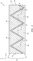
FIG. 3 is a sectional illustration of the structured panel portion ofFIG. 1 along line 3-3, in accordance with various embodiments; -
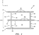
FIG. 4 is a sectional illustration of the structured panel portion ofFIG. 1 along line 4-4, in accordance with various embodiments; -
FIG. 5 is a perspective illustration of a portion of a corrugated body for the structured panel ofFIG. 1 , in accordance with various embodiments; -
FIG. 6 is another sectional illustration of the structured panel portion ofFIG. 2 , in accordance with various embodiments; -
FIG. 7 is another sectional illustration of the structured panel portion ofFIG. 4 , in accordance with various embodiments; -
FIG. 8 is a sectional illustration of a portion of a structure for the structured panel ofFIG. 1 including a top skin and a plurality of top sidewalls, in accordance with various embodiments; -
FIG. 9 is a sectional illustration of a portion of another structure for the structured panel ofFIG. 1 including the top skin and the top sidewalls, in accordance with various embodiments; -
FIG. 10 is a sectional illustration of a portion of a structure for the structured panel ofFIG. 1 including a bottom skin and a plurality of bottom sidewalls, in accordance with various embodiments; -
FIG. 11 is a sectional illustration of a portion of another structure for the structured panel ofFIG. 1 including the bottom skin and the bottom sidewalls, in accordance with various embodiments; -
FIG. 12 is a plan view of a patterned sheet of material with dashed fold lines. -
FIG. 13 is a sectional illustration of a portion of still another structure for the structured panel ofFIG. 1 including the top skin and the top sidewalls, in accordance with various embodiments; -
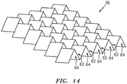
FIG. 14 is a perspective illustration of a portion of another corrugated body for the structured panel ofFIG. 1 , in accordance with various embodiments; -
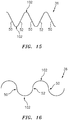
FIG. 15 is a side schematic illustration of a portion of another corrugated body for the structured panel ofFIG. 1 , in accordance with various embodiments; and -
FIG. 16 is a side schematic illustration of a portion of still another corrugated body for the structured panel ofFIG. 1 , in accordance with various embodiments. -
FIG. 1 is a cutaway perspective illustration of a portion of a structuredpanel 20; e.g., a structural acoustic panel. Thisstructured panel 20 may be configured to attenuate sound (e.g., noise) generated by an aircraft propulsion system such as, for example, a turbofan propulsion system or a turbojet propulsion system. With such a configuration, the structuredpanel 20 may be configured with a nacelle of the propulsion system. The structuredpanel 20, for example, may be configured as or with an inner or outer barrel, a translating sleeve of a thrust reverser, a blocker door, etc. Alternatively, the structuredpanel 20 may be configured with another component / structure of the aircraft such as its fuselage or a wing. Furthermore, the structuredpanel 20 may be configured to also or alternatively attenuate aircraft related sound other than that generated by the propulsion system. The structuredpanel 20 of the present disclosure, however, may alternatively be configured for non-aircraft applications. Furthermore, the structuredpanel 20 may also be configured for non-sound attenuation applications. - The structured
panel 20 ofFIG. 1 extends longitudinally along a y-axis. The structuredpanel 20 extends laterally along an x-axis. The structuredpanel 20 extends vertically along a z-axis. The term "vertical" is used herein to describe a depthwise panel direction and is not limited to a gravitational up/down direction. Furthermore, for ease of illustration, the x-y plane is shown as a generally flat plane. However, in other embodiments, the x-y plane and, thus, the structuredpanel 20 may be curved and/or follow an undulating geometry. For example, the x-y plane and, thus, the structuredpanel 20 may be arcuate, cylindrical or conical with or without radial undulations. Thus, the vertical direction may change at different locations along the x-y plane; e.g., the vertical direction may be a radial direction for a cylindrical, conical or spherical structured panel. - The structured
panel 20 includes a (e.g., acoustic) porous top skin 22 (e.g., a perforated face skin), a solid, non-perforated bottom skin 24 (e.g., a back skin) and acellular core 26. Note, the terms "top" and "bottom" are used in this disclosure to describe the relative position of an element as viewed in the figures. The present disclosure, however, is not limited to such an orientation. Furthermore, it is worth noting, thetop skin 22 may be replaced with a solid, non-perforated skin where, for example, the structuredpanel 20 is not being used for sound attenuation. - Briefly, the
cellular core 26 is disposed and extends vertically between thetop skin 22 and thebottom skin 24. Thecellular core 26 is also connected to thetop skin 22 and thebottom skin 24. Thecellular core 26, for example, may be welded, brazed, fused, adhered and/or otherwise bonded to or integral with thetop skin 22 and/or thebottom skin 24 as discussed below in further detail. - The
top skin 22 ofFIG. 1 is configured as a relatively thin sheet or layer of material that extends longitudinally and laterally along the x-y plane. This top skin material may include, but is not limited to, a metal (e.g., sheet metal), a polymer (e.g., thermoplastic or thermoset material), a fiber reinforced composite (e.g., fiberglass composite, carbon fiber composite, aramid fiber composite, etc.), or a combination thereof. Referring now toFIG. 2 , thetop skin 22 has avertical thickness 28, which extends vertically between opposing first skin top and bottom side surfaces. Thetop skin 22 includes a plurality ofpassages 30; e.g., perforations such as through-holes. Each of thesepassages 30 extends generally vertically through thetop skin 22 between its side surfaces. While thepassages 30 are described above and illustrated inFIG. 2 as through-holes for ease of description, one or more of the passages may also or alternatively be formed by one or more interconnected pores in the top skin material in alternative embodiments. - The
bottom skin 24 ofFIG. 1 is configured as a relatively thin sheet or layer of (e.g., solid, continuous and/or uninterrupted) material that extends longitudinally and laterally along the x-y plane. This bottom skin material may include, but is not limited to, a metal (e.g., sheet metal), a polymer (e.g., thermoplastic or thermoset material), a fiber reinforced composite (e.g., fiberglass composite, carbon fiber composite, aramid fiber composite, etc.), or a combination thereof. The bottom skin material may be the same as or different than the top skin material. Referring toFIG. 2 , thebottom skin 24 has avertical thickness 32, which extends vertically between opposing second skin top and bottom side surfaces. Thisvertical thickness 32 may be substantially equal to or different (e.g., greater or less) than thevertical thickness 28 of thetop skin 22. - Referring to
FIG. 1 (see alsoFIGS. 2-4 ), thecellular core 26 extends longitudinally and laterally along the x-y plane. Referring again toFIG. 2 , thecellular core 26 has avertical thickness 34, which extends vertically between opposing core sides respectively abutted against thetop skin 22 and thebottom skin 24. Thevertical thickness 34 may be substantially greater than thevertical thickness top skin 22 and/or thebottom skin 24. Thevertical thickness 34 of the core 26, for example, may be at least ten to forty times (10-40x), or more, greater than thevertical thickness skin panel 20 of the present disclosure is not limited to such an exemplary embodiment. - Referring to
FIG. 1 , thecellular core 26 includes acorrugated body 36, one or moretop sidewalls 38 and one or morebottom sidewalls 40, where thetop sidewalls 38 and thebottom sidewalls 40 are arranged on opposing sides of thecorrugated body 36. More particularly, referring toFIG. 3 , thetop sidewalls 38 are disposed vertically between thecorrugated body 36 and thetop skin 22. The bottom sidewalls 40 are disposed vertically between thecorrugated body 36 and thebottom skin 24. Each of thebottom sidewalls 40 is also aligned longitudinally with a respective one of thetop sidewalls 38 as seen inFIG. 4 ; however, in other embodiments, one or more of thetop sidewalls 38 may be longitudinally offset from a respectiveclosest bottom sidewall 40. Furthermore, while structuredpanel 20 is illustrated with a 1:1 ratio of thetop sidewalls 38 to thebottom sidewalls 40, the number oftop sidewalls 38 may be different (e.g., greater or less) than the number ofbottom sidewalls 40 in other embodiments. In still other embodiments, the structuredpanel 20 may be configured without anytop sidewalls 38 or without anybottom sidewalls 40. - Referring to
FIG. 5 , thecorrugated body 36 includes a plurality ofcorrugations 42. Thesecorrugations 42 along with thetop sidewalls 38 and thebottom sidewalls 40 are arranged together to configure thecellular core 26 as an open cavity (e.g., open cell) structure as shown inFIG. 1 . Referring toFIGS. 2 and4 , this open cavity structure forms a plurality ofcavities top cavities 44 are vertically between thecorrugated body 36 and thetop skin 22. Each of thesetop cavities 44 may be fluidly coupled with one or morerespective passages 30 in thetop skin 22. The bottom cavities 46 are vertically between thecorrugated body 36 and thebottom skin 24. Each of thesebottom cavities 46 may be fluidly coupled with a respective one of thetop cavities 44 through one or more passages 48 (e.g., perforations) in thecorrugated body 36. - Referring to
FIG. 5 , thecorrugations 42 are arranged in a laterally extending array. This arrangement provides thecorrugated body 36 with an accordion wall structure. More particularly, thecorrugations 42 are configured from at least a plurality of solid (e.g., non-perforated) baffles 50 and a plurality of porous septums 52 (e.g., perforated septums; passaged shown inFIG. 2 ). However, in other (e.g., non-sound attenuating) embodiments, one or more or each of theseptums 52 may be replaced with a solid panel similar to thebaffles 50. - Referring to
FIG. 2 , each of thebaffles 50 may be configured as a solid, continuous and/or uninterrupted panel of core material. Each of theseptums 52 may be configured as a panel of core material with one ormore passages 48; e.g., perforation such as through-holes. While thesepassages 48 are described and illustrated inFIG. 2 as through-holes for ease of description, one or more of the passages may also or alternatively be formed by one or more interconnected pores in the septum material. - Each
corrugation 42 includes a respective one of thebaffles 50 and a respective one of theseptums 52. Each of thesecorrugation portions respective corrugation 42 as shown inFIG. 5 ; however, the present disclosure is not limited to such a configuration. - Referring to
FIG. 2 , eachbaffle 50 extends laterally and/or vertically (e.g., diagonally) from its top end 54 to its bottom end 56. The top end 54 of thebaffle 50 is connected to and adjacent thetop skin 22. The bottom end 56 of thebaffle 50 is connected to and adjacent thebottom skin 24. The bottom end 56 of thebaffle 50 is also connected to and contiguous with a bottom end 58 of a respective septum 54 in thesame corrugation 42. Thisseptum 52 extends from the bottom end 58 to its top end 60. The bottom end 58 of theseptum 52 is connected to and adjacent thebottom skin 24. The top end 60 of theseptum 52 is connected to and adjacent thetop skin 22. The top end 60 of theseptum 52 may also be connected to and contiguous with the top end 54 of abaffle 50 in a laterally adjacent one of thecorrugations 42. - Referring to
FIG. 5 , each corrugation 42 forms atop channel 62 within thecorrugated body 36. Thistop channel 62 extends laterally between thebaffle 50 and theseptum 52 of thecorrugation 42. Thetop channel 62 extends vertically into thecorrugated body 36 to the interface / connection between thebaffle 50 and theseptum 52. Thetop channel 62 may also extend longitudinally along the entire longitudinal length of thecorrugation 42. - Each laterally adjacent pair of the
corrugations 42 form abottom channel 64 within thecorrugated body 36. Thebottom channel 64 extends laterally between theseptum 52 of a first of theadjacent corrugations 42 to thebaffle 50 of a second of theadjacent corrugations 42. Thebottom channel 64 extends vertically into thecorrugated body 36 to the interface / connection between therespective baffle 50 andseptum 52. Thebottom channel 64 may also extend longitudinally along the entire longitudinal lengths of the laterallyadjacent corrugations 42. Thetop channels 62 and thebottom channels 64 are positioned on opposing sides of thecorrugated body 36. - Referring to
FIGS. 1 and4 , thetop sidewalls 38 are discretely spaced longitudinally along thetop channels 62 and thecorrugations 42. Referring now toFIGS. 1 and3 , eachtop sidewall 38 extends laterally across one or more of thetop channels 62 and thecorrugations 42. For example, eachtop sidewall 38 includes one or more top sidewall elements 66 (e.g., triangular panels) arranged in a laterally extending array. - Each
top sidewall element 66 is configured with a shape that substantially matches a cross-sectional shape of a respective one of thetop channels 62. Eachtop sidewall element 66 is disposed within a respective one of thetop channels 62 and configured to substantially fluidly isolate longitudinally adjacent portions (i.e., cavities 44) of thattop channel 62 from one another. More particularly, thetop sidewall element 66 extends laterally across thetop channel 62 between therespective baffle 50 and therespective septum 52. Thetop sidewall element 66 extends vertically into thetop channel 62 from thetop skin 22 to the interface / connection between therespective baffle 50 andseptum 52. Thetop sidewall element 66 is connected to (e.g., formed integral with) thetop skin 22. Thetop sidewall element 66 is also connected to (e.g., adhered and/or otherwise bonded) to therespective baffle 50 andseptum 52. - Referring to
FIGS. 1 and4 , the bottom sidewalls 40 are discretely spaced longitudinally along thebottom channels 64 and thecorrugations 42. Referring now toFIGS. 1 and3 , eachbottom sidewall 40 extends laterally across one or more of thebottom channels 64 and thecorrugations 42. For example, eachbottom sidewall 40 includes one or more bottom sidewall elements 68 (e.g., triangular panels) arranged in a laterally extending array. - Each
bottom sidewall element 68 is configured with a shape that substantially matches a cross-sectional shape of a respective one of thebottom channels 64. Eachbottom sidewall element 68 is disposed within a respective one of thebottom channels 64 and configured to substantially fluidly isolate longitudinally adjacent portions (i.e., cavities 46) of thatbottom channel 64 from one another. More particularly, thebottom sidewall element 68 extends laterally across thebottom channel 64 between therespective baffle 50 and therespective septum 52. Thebottom sidewall element 68 extends vertically into thebottom channel 64 from thebottom skin 24 to the interface / connection between therespective baffle 50 andseptum 52. Thebottom sidewall element 68 is connected to (e.g., formed integral with) thebottom skin 24. Thebottom sidewall element 68 is also connected to (e.g., adhered and/or otherwise bonded) to therespective baffle 50 andseptum 52. - Referring to
FIGS. 6 and7 , the structuredpanel 20 includes a plurality ofresonance chambers 70. Eachresonance chamber 70 includes a respective one of thetop cavities 44 and a respective one of thebottom cavities 46. Eachresonance chamber 70 extends laterally between and is formed by a laterally adjacent pair of thebaffles 50. Each of theresonance chambers 70 extends vertically between thetop skin 22 and thebottom skin 24. Each of theresonance chambers 70 extends longitudinally between a laterally adjacent pair of thetop sidewalls 38 and a laterally adjacent pair of thebottom sidewalls 40. Eachseptum 52 is disposed within and divides a respective one of theresonance chambers 70 into fluidly coupled sub-chambers. More particularly, the passages 48 (e.g., perforations) in theseptum 52 fluidly couple the sub-chambers (i.e., the top andbottom cavities 44 and 46) together. - A length of each
resonance chamber 70 extends diagonally between thetop skin 22 and thebottom skin 24 and through a respective one of theseptums 52. The length 72 of theresonance chamber 70 therefore is longer than thevertical thickness 34 of thecellular core 26. This enables noise attenuation of relatively low frequency noise without increasing thevertical thickness 34 of thecore 26 and, thus, a vertical thickness of the structuredpanel 20. For example, eachresonance chamber 70 may receive acoustic waves through thepassages 30 in thetop skin 22. Theresonance chamber 70 may reverse the phase of one or more frequencies of those sound waves using known acoustic reflection principles and subsequently direct the reverse phase sound waves out of the structuredpanel 20 through thepassages 30 to destructively interfere with other incoming acoustic waves. - The
corrugated body 36 may be constructed from any suitable material or materials. Thecorrugated body 36, for example, may be constructed from a metal (e.g., sheet metal such as aluminum or titanium sheet metal), a polymer (e.g., thermoplastic or thermoset material), a fiber reinforced composite (e.g., fiberglass composite, carbon fiber composite, aramid fiber composite, etc.), or a combination thereof. Thecorrugated body 36 may be constructed from the same material(s) as thetop skin 22 and/or thebottom skin 24, or a different material or materials. - The top and the
bottom sidewalls sidewall sidewall respective skin FIGS. 8 and 9 , for example, thetop sidewalls 38 are formed integral with thetop skin 22. Similarly, in the embodiments ofFIGS. 10 and 11 , the bottom sidewalls 40 are formed integral with thebottom skin 24. Eachsidewall corrugated body 36; however, in other embodiments, thesidewalls 38 and/or 40 may be constructed from different material(s) than thecorrugated body 36. - Referring to
FIG. 8 , at least a portion (or an entirety) of thetop skin 22 and one or more (or each) of thetop sidewalls 38 are collectively at least partially (or completely) formed by a single ply 74 (e.g., sheet, layer) of material such as, but not limited to, a single piece of sheet metal, a single layer of fibrous material in resin (e.g., thermoplastic or thermoset) matrix, a single sheet of polymer (e.g., thermoplastic or thermoset material), etc. In the embodiment ofFIG. 8 , thetop skin 22 has a single layer construction whereas each of thesidewalls 38 has a double layer construction due to overlapping portions of theply 74 of material. However, in other embodiments for example as shown inFIG. 9 , thetop skin 22 may have a multi-layer construction where, for example, thetop skin 22 includes at least oneadditional ply 76 of material. - Referring to
FIG. 10 , at least a portion (or an entirety) of thebottom skin 24 and one or more (or each) of thebottom sidewalls 40 are similarly collectively at least partially (or completely) formed by a single ply 78 (e.g., sheet, layer) of material such as, but not limited to, a single piece of sheet metal, a single layer of fibrous material in resin (e.g., thermoplastic or thermoset) matrix, a single sheet of polymer (e.g., thermoplastic or thermoset material), etc. In the embodiment ofFIG. 10 , thebottom skin 24 has a single layer construction whereas each of thesidewalls 40 has a double layer construction due to overlapping portions of theply 78 of material. However, in other embodiments for example as shown inFIG. 11 , thebottom skin 24 may have a multi-layer construction where, for example, thebottom skin 24 includes at least oneadditional ply 80 of material. - To at least partially form a
respective skin FIG. 12 . In particular, a plurality ofcutouts FIG. 12 , thecutouts 82 are polygonal-shaped (e.g., diamond shaped) and arranged in one or more lateral arrays. Thecutouts 84 are also polygonal-shaped (e.g., triangular shaped) and arranged in one or more lateral arrays. Thecutouts FIG. 12 with one ormore segments 86; e.g., integral portions. Each of thesesegments 86 includes a (e.g., rectangular)base 88, a plurality of first (e.g., triangular or otherwise polygonal)projections 90 and a plurality of second (e.g., triangular or otherwise polygonal)projections 92. Thebase 88 is disposed between the first and thesecond projections 92 such that thefirst projections 90 are on a first side of thebase 88 and thesecond projections 92 are on a second, opposite side of thebase 88. Distal ends (e.g., peaks) of thefirst projections 90 are respectively connected to distal ends (e.g., peaks) of thesecond projections 92 of an adjacent segment, and vice versa. - After the patterning, the patterned sheet of material is folded along the fold lines 94 and 96. The fold lines 94 correspond to folds in a first direction. The fold lines 96 correspond to folds in a second, opposite direction. After the folding, each base 88 forms a portion of a
respective skin FIGS. 8-11 . Each folded over and overlapping pair ofprojections respective sidewall element FIGS. 8-11 - After the folding and the provision of at least two of the folded and patterned sheets of material, these folded and patterned sheets of material are attached (e.g., bonded) to opposing sides of the
corrugated body 36 to form the structuredpanel 20. Of course, additional sheets of material may be attached to the structure to provide, for example, multi-layer skins as shown, for example, inFIGS. 9 and11 . - In some embodiments, the
base 88 of the patterned material for thetop skin 22 may be perforated prior to the folding. In other embodiments, thetop skin 22 may be perforated after the folded and patterned sheet of material is attached to thecorrugated body 36. - Referring to
FIG. 9 , in some embodiments, theply 74 of material includes a plurality of first apertures 98 (e.g., through-holes) and theply 76 of material includes a plurality of second apertures 100 (e.g., through-holes), which are respectively laterally and longitudinally aligned with thefirst apertures 98. Eachfirst aperture 98 may have a first aperture width (e.g., diameter) that is substantially (e.g., +/- 5%) or exactly equal to a second aperture width (e.g., diameter) of a respective alignedsecond aperture 100. However, in other embodiments, the second aperture width may be sized different (e.g., greater) than the first aperture width as shown, for example, inFIG. 13 . -
FIG. 14 illustrates another embodiment of thecorrugated body 36 for the structuredpanel 20. Thiscorrugated body 36 is configured with non-linear (e.g., zig-zagging) first andsecond channels - In some embodiments, referring to
FIG. 5 , an upper orlower peak 102 between a respective pair ofbaffle 50 andseptum 52 may be sharp. In other embodiments, referring toFIG. 15 , one or more of thepeaks 102 may be blunt; e.g., curved. - In some embodiments, each
baffle 50 and/or eachseptum 52 may follow a substantially flat, linear trajectory as illustrated inFIG. 15 ; see alsoFIG. 5 . In other embodiments, eachbaffle 50 and/or eachseptum 52 may follow a curved (e.g., sinusoidal) trajectory as illustrated inFIG. 16 . - While various embodiments of the present invention have been disclosed, it will be apparent to those of ordinary skill in the art that many more embodiments and implementations are possible within the scope of the invention. For example, the present invention as described herein includes several aspects and embodiments that include particular features. Although these features may be described individually, it is within the scope of the present invention that some or all of these features may be combined with any one of the aspects and remain within the scope of the invention. Accordingly, the present invention is not to be restricted except in light of the attached claims and their equivalents.
Claims (15)
- A panel (20) for attenuating sound, comprising:a first skin (22), a second skin (24) and a core (26) between and connected to the first skin (22) and the second skin (24), the core (26) including a corrugated body (36), a first sidewall (38) and a second sidewall (40);the corrugated body (36) including a plurality of corrugations (42) configured from at least a plurality of baffles (50) and a plurality of septums (52), each of the corrugations (42) including a respective one of the baffles (50) and a respective one of the septums (52);wherein a first cavity (44) extends laterally within the core (26) from a first of the baffles (50) to a first of the septums (52), the first cavity (44) extends longitudinally within the core (26) from the first sidewall (38) to the second sidewall (40), and the first cavity (44) is fluidly coupled with a passage (30) through a first portion of the first skin (22); andwherein the first portion of the first skin (22), the first sidewall (38) and the second sidewall (40) are collectively at least partially formed by a ply (74) of material.
- The panel of claim 1, wherein the ply of material comprises thermoplastic material, thermoset material, or metal.
- The panel of claim 1 or 2, wherein the first portion of the first skin (22) is further partially formed by a second ply (76) of material that overlaps and is bonded to the ply (74) of material.
- The panel of claim 3, wherein
the ply (74) of material is configured with a first through hole (98);
the second ply (76) of material is configured with a second through hole (100) having a width that is greater than a width of the first through hole (98); and
the passage (30) is formed by at least the first through hole (98) and the second through hole (100). - The panel of any preceding claim, wherein
the core (26) further includes a third sidewall;
a second cavity extends laterally within the core from a second of the baffles (50) to a second of the septums (52), the second cavity extends longitudinally within the core (26) from the first sidewall to the third sidewall, and the second cavity is fluidly coupled with a second passage through a second portion of the first skin (22); and
the first portion of the first skin (22), the second portion of the first skin (22), the first sidewall (38), the second sidewall (40) and the third sidewall are collectively at least partially formed by the ply (74) of material. - The panel of any of claims 1 to 4, wherein
the core (26) further includes a third sidewall and a fourth sidewall;
the corrugated body (36) is between the first sidewall and the third sidewall and between the second sidewall and the fourth sidewall; and
a second cavity extends laterally within the core (26) from the first of the septums (52) to a second of the baffles (50), the second cavity extends longitudinally within the core (26) from the third sidewall to the fourth sidewall, and the second cavity is fluidly coupled with the first cavity through one or more perforations in the first of the septums (52). - The panel of claim 6, wherein a first portion of the second skin (24) bounding the second cavity, the third sidewall and the fourth sidewall are collectively at least partially formed by a or the second ply (76) of material.
- The panel of claim 6 or 7, wherein
the third sidewall is longitudinally aligned with the first sidewall (38); and
the fourth sidewall is longitudinally aligned with the second sidewall (40). - The panel of any of claims 1 to 4, wherein
a second cavity extends laterally within the core (26) from a second of the baffles (50) to a second of the septums (52), the second cavity extends longitudinally within the core (26) from the first sidewall (38) to the second sidewall (40), and the second cavity is fluidly coupled with a second passage through a second portion of the first skin (22); and
the first portion of the first skin (22), the second portion of the first skin (22), the first sidewall (38) and the second sidewall (40) are collectively at least partially formed by the ply (74) of material. - The panel of any preceding claim, wherein the first sidewall (38) and the second sidewall (40) each extend from the first skin (22) to the first of the baffles (50) and the first of the septums (52).
- The panel of any preceding claim, wherein a first portion of the ply (74) of material overlaps and is bonded to a second portion of the ply (74) of material to form at least a portion of the first sidewall (38),
wherein a third portion of the ply (74) of material optionally overlaps and may be bonded to a fourth portion of the ply (74) of material to form at least a portion of the second sidewall (40). - The panel of any preceding claim, wherein, prior to formation of the panel (20), the ply (74) of material comprises a sheet of material with one or more rows of polygonal-shaped cutouts.
- The panel of any preceding claim, wherein
the ply (74) of material comprises a plurality of segments (86);
each of the segments (86) comprisesa rectangular base (88),a plurality of first triangular projections (90) on a first side of the rectangular base (88); anda plurality of second triangular projections (92) on a second side of the rectangular base (88); andpeaks of the first triangular projections (90) of a first of the segments (86) are respectively connected to peaks of the second triangular projections (92) of a second of the segments (86). - A structured panel, comprising:a first skin, a second skin and a core between and connected to the first skin and the second skin, the core including a corrugated body, a first sidewall, a second sidewall and a third sidewall;the corrugated body including a plurality of corrugations configured from at least a plurality of baffles and a plurality of septums, each of the corrugations including a respective one of the baffles and a respective one of the porous septums;wherein a first cavity extends laterally within the core from a first of the baffles to a first of the septums, the first cavity extends longitudinally within the core from the first sidewall to the second sidewall;wherein a second cavity extends laterally within the core from a second of the baffles to a second of the septums, the second cavity extends longitudinally within the core from the second sidewall to the third sidewall; andwherein a first portion of the first skin adjacent the first cavity, a second portion of the first skin adjacent the second cavity, the first sidewall, the second sidewall and the third sidewall are collectively at least partially formed by a ply of material,wherein, optionally, the first cavity is fluidly coupled with a first passage through the first portion of the first skin, and the second cavity is fluid coupled with a second passage through the second portion of the first skin,wherein, further optionally, the first skin is a non-perforated skin.
- A method comprising forming a panel for attenuating sound, the panel comprising a porous first skin, a second skin and a cellular core connected to and between the porous first skin and the second skin, wherein the cellular core is configured with a first cavity that extends laterally between a baffle and a porous septum and longitudinally between a first sidewall and a second sidewall, wherein the forming comprises:providing a sheet of material with one or more rows of polygonal cutouts; andfolding the sheet of material such that a portion of the porous first skin bounding the first cavity, the first sidewall and the second sidewall are collectively at least partially defined by the folded sheet of material.
Applications Claiming Priority (1)
| Application Number | Priority Date | Filing Date | Title |
|---|---|---|---|
| US16/031,397 US11066147B2 (en) | 2018-07-10 | 2018-07-10 | Structured panel with integrated skin and sidewalls |
Publications (2)
| Publication Number | Publication Date |
|---|---|
| EP3594936A1 true EP3594936A1 (en) | 2020-01-15 |
| EP3594936B1 EP3594936B1 (en) | 2024-02-14 |
Family
ID=67226160
Family Applications (1)
| Application Number | Title | Priority Date | Filing Date |
|---|---|---|---|
| EP19185521.2A Active EP3594936B1 (en) | 2018-07-10 | 2019-07-10 | Structured panel with integrated skin and sidewalls |
Country Status (2)
| Country | Link |
|---|---|
| US (1) | US11066147B2 (en) |
| EP (1) | EP3594936B1 (en) |
Families Citing this family (10)
| Publication number | Priority date | Publication date | Assignee | Title |
|---|---|---|---|---|
| FR3081510B1 (en) * | 2018-05-24 | 2020-05-29 | Safran Nacelles | ACOUSTIC MITIGATION PANEL FOR AIRCRAFT TURBOREACTOR NACELLE |
| WO2022176810A1 (en) * | 2021-02-17 | 2022-08-25 | 三菱重工業株式会社 | Panel structure |
| US11925971B2 (en) * | 2021-09-10 | 2024-03-12 | Rohr, Inc. | Component with structured panel(s) and methods for forming the component |
| US12366202B2 (en) | 2022-01-18 | 2025-07-22 | General Electric Company | Bleed valve assemblies |
| US12320259B2 (en) | 2022-06-27 | 2025-06-03 | General Electric Company | Compact bleed valve assemblies |
| EP4302980B1 (en) | 2022-07-08 | 2025-04-23 | Rohr, Inc. | Forming pattern for cellular core by folding material |
| FR3147423B1 (en) * | 2023-03-31 | 2025-09-12 | Safran Nacelles | ACOUSTIC PANEL FOR AN AIRCRAFT PROPULSION UNIT, AND METHOD FOR MANUFACTURING SAME |
| US12180890B1 (en) * | 2023-06-23 | 2024-12-31 | General Electric Company | Variable bleed valve assemblies |
| US20250214712A1 (en) * | 2023-12-27 | 2025-07-03 | Rohr, Inc. | Acoustic panel for an aircraft propulsion system |
| US20250214713A1 (en) * | 2023-12-27 | 2025-07-03 | Rohr, Inc. | Acoustic panel for an aircraft propulsion system |
Citations (6)
| Publication number | Priority date | Publication date | Assignee | Title |
|---|---|---|---|---|
| US7051489B1 (en) * | 1999-08-12 | 2006-05-30 | Hunter Douglas Inc. | Ceiling system with replacement panels |
| US20080020188A1 (en) * | 2006-07-24 | 2008-01-24 | Tessellated Group | Three-dimensional support structure |
| EP2844463A1 (en) * | 2013-06-13 | 2015-03-11 | The Boeing Company | Superplastic forming/diffusion bonding structure for attenuation of noise from air flow |
| US20170301334A1 (en) * | 2016-04-15 | 2017-10-19 | Rohr, Inc. | Acoustic panel with vertical stiffeners |
| US20180142621A1 (en) * | 2016-11-18 | 2018-05-24 | Rohr, Inc. | Acoustic panel with sidewall stringers |
| US20180142622A1 (en) * | 2016-11-18 | 2018-05-24 | Rohr, Inc. | Acoustic panel with sidewall stringers |
Family Cites Families (13)
| Publication number | Priority date | Publication date | Assignee | Title |
|---|---|---|---|---|
| JPS5151535Y2 (en) | 1971-09-07 | 1976-12-10 | ||
| US3734234A (en) | 1971-11-08 | 1973-05-22 | Lockheed Aircraft Corp | Sound absorption structure |
| US7604095B2 (en) * | 2006-06-01 | 2009-10-20 | General Electric Company | Thermal-acoustic enclosure |
| JP5151535B2 (en) | 2007-02-22 | 2013-02-27 | 東レ株式会社 | Sandwich structure, molded body using the same, and electronic equipment casing |
| US8636104B2 (en) * | 2011-05-11 | 2014-01-28 | Meyer Sound Laboratories, Incorporated | Acoustically absorptive panel |
| JP6165466B2 (en) * | 2013-02-27 | 2017-07-19 | 株式会社神戸製鋼所 | Soundproof structure |
| US9476359B2 (en) * | 2014-04-11 | 2016-10-25 | Rohr, Inc. | Acoustic liner |
| CN104175616B (en) | 2014-09-16 | 2016-06-08 | 哈尔滨工业大学 | Class cellular composite material battenboard and hot-press molding method thereof |
| EP3002475B1 (en) * | 2014-09-30 | 2019-03-06 | Ellergon Antriebstechnik GmbH | Device for absorbing struture-borne sound |
| US9447576B2 (en) * | 2015-01-09 | 2016-09-20 | Rohr, Inc. | Post bond perforation of a septum in an acoustic panel |
| US9704467B1 (en) | 2016-04-15 | 2017-07-11 | Rohr, Inc. | Acoustic panel with corrugated baffles and septums |
| GB2550926B (en) | 2016-05-31 | 2018-07-25 | Bostik Ltd | Patterned self-adhesive closed-cell solid-foam insulation material |
| MX2020004824A (en) * | 2017-11-13 | 2020-10-14 | Universal Fibers Inc | Method for the manufacture of vibration damping and/or sound attenuating materials. |
-
2018
- 2018-07-10 US US16/031,397 patent/US11066147B2/en active Active
-
2019
- 2019-07-10 EP EP19185521.2A patent/EP3594936B1/en active Active
Patent Citations (6)
| Publication number | Priority date | Publication date | Assignee | Title |
|---|---|---|---|---|
| US7051489B1 (en) * | 1999-08-12 | 2006-05-30 | Hunter Douglas Inc. | Ceiling system with replacement panels |
| US20080020188A1 (en) * | 2006-07-24 | 2008-01-24 | Tessellated Group | Three-dimensional support structure |
| EP2844463A1 (en) * | 2013-06-13 | 2015-03-11 | The Boeing Company | Superplastic forming/diffusion bonding structure for attenuation of noise from air flow |
| US20170301334A1 (en) * | 2016-04-15 | 2017-10-19 | Rohr, Inc. | Acoustic panel with vertical stiffeners |
| US20180142621A1 (en) * | 2016-11-18 | 2018-05-24 | Rohr, Inc. | Acoustic panel with sidewall stringers |
| US20180142622A1 (en) * | 2016-11-18 | 2018-05-24 | Rohr, Inc. | Acoustic panel with sidewall stringers |
Also Published As
| Publication number | Publication date |
|---|---|
| EP3594936B1 (en) | 2024-02-14 |
| US20200017189A1 (en) | 2020-01-16 |
| US11066147B2 (en) | 2021-07-20 |
Similar Documents
| Publication | Publication Date | Title |
|---|---|---|
| EP3594936B1 (en) | Structured panel with integrated skin and sidewalls | |
| EP3324400B1 (en) | Acoustic panel with sidewall stringers | |
| EP3205574B1 (en) | Structural, cellular core with corrugated support walls | |
| EP3324401B1 (en) | Acoustic panel with sidewall stringers | |
| EP3422342B1 (en) | Acoustic panel with folding chamber | |
| EP3206203B1 (en) | Acoustic panel with angled corrugated core structures | |
| EP3232435B1 (en) | Acoustic panel with corrugated baffles and septums | |
| US9978354B2 (en) | Acoustic panel with vertical stiffeners | |
| US11242822B2 (en) | Structured panel with multi-panel structure(s) | |
| US11359577B2 (en) | Multi-degree of freedom acoustic panel | |
| EP3748627B1 (en) | Acoustic panel with one or more structural stiffeners | |
| US10695986B2 (en) | Method for forming a structural panel | |
| US20170167291A1 (en) | Multi-degree of freedom acoustic panel | |
| US20240271572A1 (en) | Acoustic panel with multiple layer corrugated core | |
| US10906659B2 (en) | Structured panel with structural reinforcement(s) | |
| RU2015137413A (en) | DESIGN ON THE BASIS OF SUPERPLASTIC FORMATION / DIFFUSIVE BONDING TO REDUCE NOISE FROM AIR FLOW |
Legal Events
| Date | Code | Title | Description |
|---|---|---|---|
| PUAI | Public reference made under article 153(3) epc to a published international application that has entered the european phase |
Free format text: ORIGINAL CODE: 0009012 |
|
| STAA | Information on the status of an ep patent application or granted ep patent |
Free format text: STATUS: THE APPLICATION HAS BEEN PUBLISHED |
|
| AK | Designated contracting states |
Kind code of ref document: A1 Designated state(s): AL AT BE BG CH CY CZ DE DK EE ES FI FR GB GR HR HU IE IS IT LI LT LU LV MC MK MT NL NO PL PT RO RS SE SI SK SM TR |
|
| AX | Request for extension of the european patent |
Extension state: BA ME |
|
| STAA | Information on the status of an ep patent application or granted ep patent |
Free format text: STATUS: REQUEST FOR EXAMINATION WAS MADE |
|
| 17P | Request for examination filed |
Effective date: 20200714 |
|
| RBV | Designated contracting states (corrected) |
Designated state(s): AL AT BE BG CH CY CZ DE DK EE ES FI FR GB GR HR HU IE IS IT LI LT LU LV MC MK MT NL NO PL PT RO RS SE SI SK SM TR |
|
| STAA | Information on the status of an ep patent application or granted ep patent |
Free format text: STATUS: EXAMINATION IS IN PROGRESS |
|
| 17Q | First examination report despatched |
Effective date: 20210518 |
|
| REG | Reference to a national code |
Ref country code: DE Ref legal event code: R079 Free format text: PREVIOUS MAIN CLASS: G10K0011172000 Ipc: B32B0003260000 Ref document number: 602019046404 Country of ref document: DE |
|
| RIC1 | Information provided on ipc code assigned before grant |
Ipc: F02C 7/045 20060101ALI20230724BHEP Ipc: B32B 3/12 20060101ALI20230724BHEP Ipc: G10K 11/172 20060101ALI20230724BHEP Ipc: B32B 27/06 20060101ALI20230724BHEP Ipc: B32B 15/08 20060101ALI20230724BHEP Ipc: B32B 3/28 20060101ALI20230724BHEP Ipc: B32B 3/26 20060101AFI20230724BHEP |
|
| GRAP | Despatch of communication of intention to grant a patent |
Free format text: ORIGINAL CODE: EPIDOSNIGR1 |
|
| STAA | Information on the status of an ep patent application or granted ep patent |
Free format text: STATUS: GRANT OF PATENT IS INTENDED |
|
| INTG | Intention to grant announced |
Effective date: 20230908 |
|
| GRAS | Grant fee paid |
Free format text: ORIGINAL CODE: EPIDOSNIGR3 |
|
| GRAA | (expected) grant |
Free format text: ORIGINAL CODE: 0009210 |
|
| STAA | Information on the status of an ep patent application or granted ep patent |
Free format text: STATUS: THE PATENT HAS BEEN GRANTED |
|
| AK | Designated contracting states |
Kind code of ref document: B1 Designated state(s): AL AT BE BG CH CY CZ DE DK EE ES FI FR GB GR HR HU IE IS IT LI LT LU LV MC MK MT NL NO PL PT RO RS SE SI SK SM TR |
|
| REG | Reference to a national code |
Ref country code: GB Ref legal event code: FG4D |
|
| REG | Reference to a national code |
Ref country code: CH Ref legal event code: EP |
|
| REG | Reference to a national code |
Ref country code: DE Ref legal event code: R096 Ref document number: 602019046404 Country of ref document: DE |
|
| REG | Reference to a national code |
Ref country code: IE Ref legal event code: FG4D |
|
| REG | Reference to a national code |
Ref country code: LT Ref legal event code: MG9D |
|
| REG | Reference to a national code |
Ref country code: NL Ref legal event code: MP Effective date: 20240214 |
|
| PG25 | Lapsed in a contracting state [announced via postgrant information from national office to epo] |
Ref country code: IS Free format text: LAPSE BECAUSE OF FAILURE TO SUBMIT A TRANSLATION OF THE DESCRIPTION OR TO PAY THE FEE WITHIN THE PRESCRIBED TIME-LIMIT Effective date: 20240614 |
|
| PG25 | Lapsed in a contracting state [announced via postgrant information from national office to epo] |
Ref country code: LT Free format text: LAPSE BECAUSE OF FAILURE TO SUBMIT A TRANSLATION OF THE DESCRIPTION OR TO PAY THE FEE WITHIN THE PRESCRIBED TIME-LIMIT Effective date: 20240214 |
|
| PG25 | Lapsed in a contracting state [announced via postgrant information from national office to epo] |
Ref country code: GR Free format text: LAPSE BECAUSE OF FAILURE TO SUBMIT A TRANSLATION OF THE DESCRIPTION OR TO PAY THE FEE WITHIN THE PRESCRIBED TIME-LIMIT Effective date: 20240515 |
|
| REG | Reference to a national code |
Ref country code: AT Ref legal event code: MK05 Ref document number: 1656713 Country of ref document: AT Kind code of ref document: T Effective date: 20240214 |
|
| PG25 | Lapsed in a contracting state [announced via postgrant information from national office to epo] |
Ref country code: RS Free format text: LAPSE BECAUSE OF FAILURE TO SUBMIT A TRANSLATION OF THE DESCRIPTION OR TO PAY THE FEE WITHIN THE PRESCRIBED TIME-LIMIT Effective date: 20240514 Ref country code: NL Free format text: LAPSE BECAUSE OF FAILURE TO SUBMIT A TRANSLATION OF THE DESCRIPTION OR TO PAY THE FEE WITHIN THE PRESCRIBED TIME-LIMIT Effective date: 20240214 Ref country code: HR Free format text: LAPSE BECAUSE OF FAILURE TO SUBMIT A TRANSLATION OF THE DESCRIPTION OR TO PAY THE FEE WITHIN THE PRESCRIBED TIME-LIMIT Effective date: 20240214 |
|
| PG25 | Lapsed in a contracting state [announced via postgrant information from national office to epo] |
Ref country code: ES Free format text: LAPSE BECAUSE OF FAILURE TO SUBMIT A TRANSLATION OF THE DESCRIPTION OR TO PAY THE FEE WITHIN THE PRESCRIBED TIME-LIMIT Effective date: 20240214 |
|
| PG25 | Lapsed in a contracting state [announced via postgrant information from national office to epo] |
Ref country code: AT Free format text: LAPSE BECAUSE OF FAILURE TO SUBMIT A TRANSLATION OF THE DESCRIPTION OR TO PAY THE FEE WITHIN THE PRESCRIBED TIME-LIMIT Effective date: 20240214 |
|
| PG25 | Lapsed in a contracting state [announced via postgrant information from national office to epo] |
Ref country code: RS Free format text: LAPSE BECAUSE OF FAILURE TO SUBMIT A TRANSLATION OF THE DESCRIPTION OR TO PAY THE FEE WITHIN THE PRESCRIBED TIME-LIMIT Effective date: 20240514 Ref country code: NO Free format text: LAPSE BECAUSE OF FAILURE TO SUBMIT A TRANSLATION OF THE DESCRIPTION OR TO PAY THE FEE WITHIN THE PRESCRIBED TIME-LIMIT Effective date: 20240514 Ref country code: NL Free format text: LAPSE BECAUSE OF FAILURE TO SUBMIT A TRANSLATION OF THE DESCRIPTION OR TO PAY THE FEE WITHIN THE PRESCRIBED TIME-LIMIT Effective date: 20240214 Ref country code: LT Free format text: LAPSE BECAUSE OF FAILURE TO SUBMIT A TRANSLATION OF THE DESCRIPTION OR TO PAY THE FEE WITHIN THE PRESCRIBED TIME-LIMIT Effective date: 20240214 Ref country code: IS Free format text: LAPSE BECAUSE OF FAILURE TO SUBMIT A TRANSLATION OF THE DESCRIPTION OR TO PAY THE FEE WITHIN THE PRESCRIBED TIME-LIMIT Effective date: 20240614 Ref country code: HR Free format text: LAPSE BECAUSE OF FAILURE TO SUBMIT A TRANSLATION OF THE DESCRIPTION OR TO PAY THE FEE WITHIN THE PRESCRIBED TIME-LIMIT Effective date: 20240214 Ref country code: GR Free format text: LAPSE BECAUSE OF FAILURE TO SUBMIT A TRANSLATION OF THE DESCRIPTION OR TO PAY THE FEE WITHIN THE PRESCRIBED TIME-LIMIT Effective date: 20240515 Ref country code: FI Free format text: LAPSE BECAUSE OF FAILURE TO SUBMIT A TRANSLATION OF THE DESCRIPTION OR TO PAY THE FEE WITHIN THE PRESCRIBED TIME-LIMIT Effective date: 20240214 Ref country code: ES Free format text: LAPSE BECAUSE OF FAILURE TO SUBMIT A TRANSLATION OF THE DESCRIPTION OR TO PAY THE FEE WITHIN THE PRESCRIBED TIME-LIMIT Effective date: 20240214 Ref country code: BG Free format text: LAPSE BECAUSE OF FAILURE TO SUBMIT A TRANSLATION OF THE DESCRIPTION OR TO PAY THE FEE WITHIN THE PRESCRIBED TIME-LIMIT Effective date: 20240214 Ref country code: AT Free format text: LAPSE BECAUSE OF FAILURE TO SUBMIT A TRANSLATION OF THE DESCRIPTION OR TO PAY THE FEE WITHIN THE PRESCRIBED TIME-LIMIT Effective date: 20240214 |
|
| PG25 | Lapsed in a contracting state [announced via postgrant information from national office to epo] |
Ref country code: PL Free format text: LAPSE BECAUSE OF FAILURE TO SUBMIT A TRANSLATION OF THE DESCRIPTION OR TO PAY THE FEE WITHIN THE PRESCRIBED TIME-LIMIT Effective date: 20240214 Ref country code: PT Free format text: LAPSE BECAUSE OF FAILURE TO SUBMIT A TRANSLATION OF THE DESCRIPTION OR TO PAY THE FEE WITHIN THE PRESCRIBED TIME-LIMIT Effective date: 20240614 |
|
| PG25 | Lapsed in a contracting state [announced via postgrant information from national office to epo] |
Ref country code: SE Free format text: LAPSE BECAUSE OF FAILURE TO SUBMIT A TRANSLATION OF THE DESCRIPTION OR TO PAY THE FEE WITHIN THE PRESCRIBED TIME-LIMIT Effective date: 20240214 Ref country code: PT Free format text: LAPSE BECAUSE OF FAILURE TO SUBMIT A TRANSLATION OF THE DESCRIPTION OR TO PAY THE FEE WITHIN THE PRESCRIBED TIME-LIMIT Effective date: 20240614 Ref country code: PL Free format text: LAPSE BECAUSE OF FAILURE TO SUBMIT A TRANSLATION OF THE DESCRIPTION OR TO PAY THE FEE WITHIN THE PRESCRIBED TIME-LIMIT Effective date: 20240214 Ref country code: LV Free format text: LAPSE BECAUSE OF FAILURE TO SUBMIT A TRANSLATION OF THE DESCRIPTION OR TO PAY THE FEE WITHIN THE PRESCRIBED TIME-LIMIT Effective date: 20240214 |
|
| PG25 | Lapsed in a contracting state [announced via postgrant information from national office to epo] |
Ref country code: DK Free format text: LAPSE BECAUSE OF FAILURE TO SUBMIT A TRANSLATION OF THE DESCRIPTION OR TO PAY THE FEE WITHIN THE PRESCRIBED TIME-LIMIT Effective date: 20240214 |
|
| PG25 | Lapsed in a contracting state [announced via postgrant information from national office to epo] |
Ref country code: SM Free format text: LAPSE BECAUSE OF FAILURE TO SUBMIT A TRANSLATION OF THE DESCRIPTION OR TO PAY THE FEE WITHIN THE PRESCRIBED TIME-LIMIT Effective date: 20240214 |
|
| PG25 | Lapsed in a contracting state [announced via postgrant information from national office to epo] |
Ref country code: CZ Free format text: LAPSE BECAUSE OF FAILURE TO SUBMIT A TRANSLATION OF THE DESCRIPTION OR TO PAY THE FEE WITHIN THE PRESCRIBED TIME-LIMIT Effective date: 20240214 Ref country code: EE Free format text: LAPSE BECAUSE OF FAILURE TO SUBMIT A TRANSLATION OF THE DESCRIPTION OR TO PAY THE FEE WITHIN THE PRESCRIBED TIME-LIMIT Effective date: 20240214 |
|
| PG25 | Lapsed in a contracting state [announced via postgrant information from national office to epo] |
Ref country code: SK Free format text: LAPSE BECAUSE OF FAILURE TO SUBMIT A TRANSLATION OF THE DESCRIPTION OR TO PAY THE FEE WITHIN THE PRESCRIBED TIME-LIMIT Effective date: 20240214 |
|
| PG25 | Lapsed in a contracting state [announced via postgrant information from national office to epo] |
Ref country code: SM Free format text: LAPSE BECAUSE OF FAILURE TO SUBMIT A TRANSLATION OF THE DESCRIPTION OR TO PAY THE FEE WITHIN THE PRESCRIBED TIME-LIMIT Effective date: 20240214 Ref country code: SK Free format text: LAPSE BECAUSE OF FAILURE TO SUBMIT A TRANSLATION OF THE DESCRIPTION OR TO PAY THE FEE WITHIN THE PRESCRIBED TIME-LIMIT Effective date: 20240214 Ref country code: RO Free format text: LAPSE BECAUSE OF FAILURE TO SUBMIT A TRANSLATION OF THE DESCRIPTION OR TO PAY THE FEE WITHIN THE PRESCRIBED TIME-LIMIT Effective date: 20240214 Ref country code: EE Free format text: LAPSE BECAUSE OF FAILURE TO SUBMIT A TRANSLATION OF THE DESCRIPTION OR TO PAY THE FEE WITHIN THE PRESCRIBED TIME-LIMIT Effective date: 20240214 Ref country code: DK Free format text: LAPSE BECAUSE OF FAILURE TO SUBMIT A TRANSLATION OF THE DESCRIPTION OR TO PAY THE FEE WITHIN THE PRESCRIBED TIME-LIMIT Effective date: 20240214 Ref country code: CZ Free format text: LAPSE BECAUSE OF FAILURE TO SUBMIT A TRANSLATION OF THE DESCRIPTION OR TO PAY THE FEE WITHIN THE PRESCRIBED TIME-LIMIT Effective date: 20240214 |
|
| REG | Reference to a national code |
Ref country code: DE Ref legal event code: R097 Ref document number: 602019046404 Country of ref document: DE |
|
| PG25 | Lapsed in a contracting state [announced via postgrant information from national office to epo] |
Ref country code: IT Free format text: LAPSE BECAUSE OF FAILURE TO SUBMIT A TRANSLATION OF THE DESCRIPTION OR TO PAY THE FEE WITHIN THE PRESCRIBED TIME-LIMIT Effective date: 20240214 |
|
| PLBE | No opposition filed within time limit |
Free format text: ORIGINAL CODE: 0009261 |
|
| STAA | Information on the status of an ep patent application or granted ep patent |
Free format text: STATUS: NO OPPOSITION FILED WITHIN TIME LIMIT |
|
| PG25 | Lapsed in a contracting state [announced via postgrant information from national office to epo] |
Ref country code: IT Free format text: LAPSE BECAUSE OF FAILURE TO SUBMIT A TRANSLATION OF THE DESCRIPTION OR TO PAY THE FEE WITHIN THE PRESCRIBED TIME-LIMIT Effective date: 20240214 |
|
| 26N | No opposition filed |
Effective date: 20241115 |
|
| PG25 | Lapsed in a contracting state [announced via postgrant information from national office to epo] |
Ref country code: MC Free format text: LAPSE BECAUSE OF FAILURE TO SUBMIT A TRANSLATION OF THE DESCRIPTION OR TO PAY THE FEE WITHIN THE PRESCRIBED TIME-LIMIT Effective date: 20240214 |
|
| REG | Reference to a national code |
Ref country code: CH Ref legal event code: PL |
|
| PG25 | Lapsed in a contracting state [announced via postgrant information from national office to epo] |
Ref country code: LU Free format text: LAPSE BECAUSE OF NON-PAYMENT OF DUE FEES Effective date: 20240710 |
|
| PG25 | Lapsed in a contracting state [announced via postgrant information from national office to epo] |
Ref country code: LU Free format text: LAPSE BECAUSE OF NON-PAYMENT OF DUE FEES Effective date: 20240710 |
|
| PG25 | Lapsed in a contracting state [announced via postgrant information from national office to epo] |
Ref country code: SI Free format text: LAPSE BECAUSE OF FAILURE TO SUBMIT A TRANSLATION OF THE DESCRIPTION OR TO PAY THE FEE WITHIN THE PRESCRIBED TIME-LIMIT Effective date: 20240214 Ref country code: CH Free format text: LAPSE BECAUSE OF NON-PAYMENT OF DUE FEES Effective date: 20240731 Ref country code: BE Free format text: LAPSE BECAUSE OF NON-PAYMENT OF DUE FEES Effective date: 20240731 |
|
| REG | Reference to a national code |
Ref country code: BE Ref legal event code: MM Effective date: 20240731 |
|
| PGFP | Annual fee paid to national office [announced via postgrant information from national office to epo] |
Ref country code: GB Payment date: 20250619 Year of fee payment: 7 |
|
| PGFP | Annual fee paid to national office [announced via postgrant information from national office to epo] |
Ref country code: FR Payment date: 20250620 Year of fee payment: 7 |
|
| PG25 | Lapsed in a contracting state [announced via postgrant information from national office to epo] |
Ref country code: IE Free format text: LAPSE BECAUSE OF NON-PAYMENT OF DUE FEES Effective date: 20240710 |
|
| PGFP | Annual fee paid to national office [announced via postgrant information from national office to epo] |
Ref country code: DE Payment date: 20250620 Year of fee payment: 7 |
|
| PG25 | Lapsed in a contracting state [announced via postgrant information from national office to epo] |
Ref country code: CY Free format text: LAPSE BECAUSE OF FAILURE TO SUBMIT A TRANSLATION OF THE DESCRIPTION OR TO PAY THE FEE WITHIN THE PRESCRIBED TIME-LIMIT; INVALID AB INITIO Effective date: 20190710 |
|
| PG25 | Lapsed in a contracting state [announced via postgrant information from national office to epo] |
Ref country code: HU Free format text: LAPSE BECAUSE OF FAILURE TO SUBMIT A TRANSLATION OF THE DESCRIPTION OR TO PAY THE FEE WITHIN THE PRESCRIBED TIME-LIMIT; INVALID AB INITIO Effective date: 20190710 |