EP3594599A1 - Loop heat pipe - Google Patents
Loop heat pipe Download PDFInfo
- Publication number
- EP3594599A1 EP3594599A1 EP19185802.6A EP19185802A EP3594599A1 EP 3594599 A1 EP3594599 A1 EP 3594599A1 EP 19185802 A EP19185802 A EP 19185802A EP 3594599 A1 EP3594599 A1 EP 3594599A1
- Authority
- EP
- European Patent Office
- Prior art keywords
- pipe
- porous body
- working fluid
- evaporator
- liquid pipe
- Prior art date
- Legal status (The legal status is an assumption and is not a legal conclusion. Google has not performed a legal analysis and makes no representation as to the accuracy of the status listed.)
- Granted
Links
Images








Classifications
-
- F—MECHANICAL ENGINEERING; LIGHTING; HEATING; WEAPONS; BLASTING
- F28—HEAT EXCHANGE IN GENERAL
- F28D—HEAT-EXCHANGE APPARATUS, NOT PROVIDED FOR IN ANOTHER SUBCLASS, IN WHICH THE HEAT-EXCHANGE MEDIA DO NOT COME INTO DIRECT CONTACT
- F28D15/00—Heat-exchange apparatus with the intermediate heat-transfer medium in closed tubes passing into or through the conduit walls ; Heat-exchange apparatus employing intermediate heat-transfer medium or bodies
- F28D15/02—Heat-exchange apparatus with the intermediate heat-transfer medium in closed tubes passing into or through the conduit walls ; Heat-exchange apparatus employing intermediate heat-transfer medium or bodies in which the medium condenses and evaporates, e.g. heat pipes
- F28D15/04—Heat-exchange apparatus with the intermediate heat-transfer medium in closed tubes passing into or through the conduit walls ; Heat-exchange apparatus employing intermediate heat-transfer medium or bodies in which the medium condenses and evaporates, e.g. heat pipes with tubes having a capillary structure
- F28D15/043—Heat-exchange apparatus with the intermediate heat-transfer medium in closed tubes passing into or through the conduit walls ; Heat-exchange apparatus employing intermediate heat-transfer medium or bodies in which the medium condenses and evaporates, e.g. heat pipes with tubes having a capillary structure forming loops, e.g. capillary pumped loops
-
- F—MECHANICAL ENGINEERING; LIGHTING; HEATING; WEAPONS; BLASTING
- F28—HEAT EXCHANGE IN GENERAL
- F28D—HEAT-EXCHANGE APPARATUS, NOT PROVIDED FOR IN ANOTHER SUBCLASS, IN WHICH THE HEAT-EXCHANGE MEDIA DO NOT COME INTO DIRECT CONTACT
- F28D15/00—Heat-exchange apparatus with the intermediate heat-transfer medium in closed tubes passing into or through the conduit walls ; Heat-exchange apparatus employing intermediate heat-transfer medium or bodies
- F28D15/02—Heat-exchange apparatus with the intermediate heat-transfer medium in closed tubes passing into or through the conduit walls ; Heat-exchange apparatus employing intermediate heat-transfer medium or bodies in which the medium condenses and evaporates, e.g. heat pipes
- F28D15/0266—Heat-exchange apparatus with the intermediate heat-transfer medium in closed tubes passing into or through the conduit walls ; Heat-exchange apparatus employing intermediate heat-transfer medium or bodies in which the medium condenses and evaporates, e.g. heat pipes with separate evaporating and condensing chambers connected by at least one conduit; Loop-type heat pipes; with multiple or common evaporating or condensing chambers
-
- F—MECHANICAL ENGINEERING; LIGHTING; HEATING; WEAPONS; BLASTING
- F28—HEAT EXCHANGE IN GENERAL
- F28D—HEAT-EXCHANGE APPARATUS, NOT PROVIDED FOR IN ANOTHER SUBCLASS, IN WHICH THE HEAT-EXCHANGE MEDIA DO NOT COME INTO DIRECT CONTACT
- F28D15/00—Heat-exchange apparatus with the intermediate heat-transfer medium in closed tubes passing into or through the conduit walls ; Heat-exchange apparatus employing intermediate heat-transfer medium or bodies
- F28D15/02—Heat-exchange apparatus with the intermediate heat-transfer medium in closed tubes passing into or through the conduit walls ; Heat-exchange apparatus employing intermediate heat-transfer medium or bodies in which the medium condenses and evaporates, e.g. heat pipes
- F28D15/0233—Heat-exchange apparatus with the intermediate heat-transfer medium in closed tubes passing into or through the conduit walls ; Heat-exchange apparatus employing intermediate heat-transfer medium or bodies in which the medium condenses and evaporates, e.g. heat pipes the conduits having a particular shape, e.g. non-circular cross-section, annular
-
- F—MECHANICAL ENGINEERING; LIGHTING; HEATING; WEAPONS; BLASTING
- F28—HEAT EXCHANGE IN GENERAL
- F28D—HEAT-EXCHANGE APPARATUS, NOT PROVIDED FOR IN ANOTHER SUBCLASS, IN WHICH THE HEAT-EXCHANGE MEDIA DO NOT COME INTO DIRECT CONTACT
- F28D15/00—Heat-exchange apparatus with the intermediate heat-transfer medium in closed tubes passing into or through the conduit walls ; Heat-exchange apparatus employing intermediate heat-transfer medium or bodies
- F28D15/02—Heat-exchange apparatus with the intermediate heat-transfer medium in closed tubes passing into or through the conduit walls ; Heat-exchange apparatus employing intermediate heat-transfer medium or bodies in which the medium condenses and evaporates, e.g. heat pipes
- F28D15/0283—Means for filling or sealing heat pipes
-
- F—MECHANICAL ENGINEERING; LIGHTING; HEATING; WEAPONS; BLASTING
- F28—HEAT EXCHANGE IN GENERAL
- F28D—HEAT-EXCHANGE APPARATUS, NOT PROVIDED FOR IN ANOTHER SUBCLASS, IN WHICH THE HEAT-EXCHANGE MEDIA DO NOT COME INTO DIRECT CONTACT
- F28D15/00—Heat-exchange apparatus with the intermediate heat-transfer medium in closed tubes passing into or through the conduit walls ; Heat-exchange apparatus employing intermediate heat-transfer medium or bodies
- F28D15/02—Heat-exchange apparatus with the intermediate heat-transfer medium in closed tubes passing into or through the conduit walls ; Heat-exchange apparatus employing intermediate heat-transfer medium or bodies in which the medium condenses and evaporates, e.g. heat pipes
- F28D15/04—Heat-exchange apparatus with the intermediate heat-transfer medium in closed tubes passing into or through the conduit walls ; Heat-exchange apparatus employing intermediate heat-transfer medium or bodies in which the medium condenses and evaporates, e.g. heat pipes with tubes having a capillary structure
-
- F—MECHANICAL ENGINEERING; LIGHTING; HEATING; WEAPONS; BLASTING
- F28—HEAT EXCHANGE IN GENERAL
- F28D—HEAT-EXCHANGE APPARATUS, NOT PROVIDED FOR IN ANOTHER SUBCLASS, IN WHICH THE HEAT-EXCHANGE MEDIA DO NOT COME INTO DIRECT CONTACT
- F28D15/00—Heat-exchange apparatus with the intermediate heat-transfer medium in closed tubes passing into or through the conduit walls ; Heat-exchange apparatus employing intermediate heat-transfer medium or bodies
- F28D15/02—Heat-exchange apparatus with the intermediate heat-transfer medium in closed tubes passing into or through the conduit walls ; Heat-exchange apparatus employing intermediate heat-transfer medium or bodies in which the medium condenses and evaporates, e.g. heat pipes
- F28D15/04—Heat-exchange apparatus with the intermediate heat-transfer medium in closed tubes passing into or through the conduit walls ; Heat-exchange apparatus employing intermediate heat-transfer medium or bodies in which the medium condenses and evaporates, e.g. heat pipes with tubes having a capillary structure
- F28D15/046—Heat-exchange apparatus with the intermediate heat-transfer medium in closed tubes passing into or through the conduit walls ; Heat-exchange apparatus employing intermediate heat-transfer medium or bodies in which the medium condenses and evaporates, e.g. heat pipes with tubes having a capillary structure characterised by the material or the construction of the capillary structure
-
- F—MECHANICAL ENGINEERING; LIGHTING; HEATING; WEAPONS; BLASTING
- F28—HEAT EXCHANGE IN GENERAL
- F28D—HEAT-EXCHANGE APPARATUS, NOT PROVIDED FOR IN ANOTHER SUBCLASS, IN WHICH THE HEAT-EXCHANGE MEDIA DO NOT COME INTO DIRECT CONTACT
- F28D21/00—Heat-exchange apparatus not covered by any of the groups F28D1/00 - F28D20/00
- F28D2021/0019—Other heat exchangers for particular applications; Heat exchange systems not otherwise provided for
- F28D2021/0028—Other heat exchangers for particular applications; Heat exchange systems not otherwise provided for for cooling heat generating elements, e.g. for cooling electronic components or electric devices
Definitions
- the present disclosure relates to a loop heat pipe.
- Heat pipes are known as devices for cooling a heat generation component such as a CPU (central processing unit) that is installed in an electronic device.
- the heat pipe is a device that transports heat utilizing phase transition of a working fluid.
- An example heat pipe is a loop heat pipe that is equipped with an evaporator that evaporates working fluid by heat generated by a heat generation component and a condenser that condenses evaporated working fluid by cooling it, and in which the evaporator and the condenser are connected to each other by a liquid pipe and a vapor pipe that form a loop-shaped flow channel.
- the working fluid flows through a loop-shaped flow channel in one direction.
- a porous body is provided in a liquid pipe of a loop heat pipe, and working fluid in the liquid pipe is guided to the evaporator by capillary forces generated in the porous body, whereby a reverse flow of vapor from the evaporator to the liquid pipe is suppressed.
- a number of pores are formed in the porous body. Pores are formed by laying, one on another, metal layers through each of which through-holes are formed in such a manner that adjacent through-holes overlap with each other. Refer to Japanese Patent No. 6,146,484 , for example.
- Certain embodiments provide a loop heat pipe.
- the loop heat pipe comprises:
- the porous body is disposed to be in contact with the first pipe wall.
- Fig. 1 is a schematic plan view of a loop heat pipe as a reference example.
- a loop heat pipe 900 of the reference example is equipped with an evaporator 910, a condenser 920, a vapor pipe 930, and a liquid pipe 940.
- the evaporator 910 is configured to generate vapor Cv by evaporating working fluid C.
- the condenser 920 is configured to condense the vapor Cv.
- the evaporator 910 and the condenser 920 are connected to each other by the vapor pipe 930 and the liquid pipe 940, and the vapor pipe 930 and the liquid pipe 940 form a flow channel that is a loop through which the working fluid C or the vapor Cv flows.
- the liquid pipe 940 is formed with an injection inlet 941 through which working fluid C is injected.
- the injection inlet 941 is sealed after injection of working fluid C.
- Figs. 2A and 2B show an example inside structure of the liquid pipe 940 of the loop heat pipe as the reference example.
- Fig. 2A is a partial schematic plan view and Fig. 2B is a sectional view taken along line I-I in Fig. 2A.
- Fig. 2A is drawn in such a manner that the uppermost one of metal layers shown in Fig. 2B is omitted.
- a prop-like porous body 950 is disposed at the center, in a plan view, of the liquid pipe 940.
- the porous body 950 extends along the liquid pipe 940 from the condenser 920 to the evaporator 910, and the flow channel of the liquid pipe 940 is divided into two channels, that is, an outside flow channel 946 which is formed outside the porous body 950 and an inside flow channel 947 which is formed inside the porous body 950.
- the injection inlet 941 communicates with the outside flow channel 946.
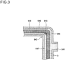
- FIG. 3 is a partial schematic plan view showing part of the liquid pipe 940 employed in the reference example and working fluid C flowing through it.
- Working fluid C also flows into the inside flow channel 947 while permeating through the porous body 950.
- the porous body 950 obstructs movement of working fluid C to not a small extent, working fluid C flows into portions of the inside flow channel 947 discontinuously.
- air bubbles 948 are prone to remain in the inside flow channel 947, particularly in the vicinity of a bent portion 945 of the liquid pipe 940.
- the air bubbles 948 existing in the liquid pipe 940 obstruct flow of liquid-phase working fluid C, possibly resulting in unexpected reduction in heat transport performance. Furthermore, the air bubbles 948 may cause the liquid pipe 940 to swell when the loop heat pipe 900 receives heat. Such swelling may lower the mechanical strength of the liquid pipe 940.
- a first embodiment will be described below which relates to a loop heat pipe.
- Fig. 4 is a schematic plan view showing a loop heat pipe 100 according to the first embodiment.
- the loop heat pipe 100 is equipped with an evaporator 110, a condenser 120, a vapor pipe 130, and a liquid pipe 140.
- the loop heat pipe 100 can be housed in a mobile electronic device 102 such as a smartphone or a tablet terminal.
- the evaporator 110 is configured to generate vapor Cv by evaporating working fluid C.
- the condenser 120 is configured to condense the vapor Cv.
- the evaporator 110 and the condenser 120 are connected to each other by the vapor pipe 130 and the liquid pipe 140, and the vapor pipe 130 and the liquid pipe140 form a flow channel that is a loop through which the working fluid C or the vapor Cv flows.
- the liquid pipe 140 is formed with an injection inlet 141 through which working fluid C is injected.
- the injection inlet 141 is closed after injection of working fluid C.
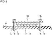
- Fig. 5 is a sectional view showing the evaporator 110 and its neighborhood of the loop heat pipe 100 according to the first embodiment.
- the evaporator 110 is formed with four through-holes 110x, for example.
- the evaporator 110 is fixed to a circuit board 10 by inserting bolts 15 through the respective through-holes 110x and engaging nuts 16 with them from the side of the bottom surface of the circuit board 10.
- a heat generation component 12 such as a CPU is mounted on the circuit board 10 via bumps 11, and the top surface of the heat generation component 12 is in close contact with the bottom surface of the evaporator 110.
- the working fluid C in the evaporator 110 is evaporated by heat generated by the heat generation component 12 and vapor Cv is thereby generated.
- vapor Cv generated by the evaporator 110 is guided to the condenser 120 through the vapor pipe 130 and condensed in the condenser 120.
- heat that was generated by the heat generation component 12 is moved to the condenser 120, whereby temperature increase of the heat generation component 12 is suppressed.
- Working fluid C produced by the condenser 120 through condensing process passes through the liquid pipe 140 and is thereby guided to the evaporator 110.
- the widths W 1 and W 2 of the vapor pipe 130 and the liquid pipe 140 may be set at about 8 mm and 6 mm, respectively.
- the widths W 1 and W 2 of the vapor pipe 130 and the liquid pipe 140 are not limited to these values and may be identical, for example.
- the working fluid C there are no particular limitations on the kind of the working fluid C.
- a fluid having a high saturated vapor pressure and a large heat of evaporation examples include ammonia, water, chlorofluorocarbon, alcohol, and acetone.
- each of the evaporator 110, the condenser 120, the vapor pipe 130, and the liquid pipe 140 may have, for example a structure in which plural metal layers are stacked one on another.
- the metal layers are, for example, copper layers which are superior in heat conductivity and are joined to each other directly by solid-phase joining or the like.
- the thickness of each metal layer may be about 50 to 200 ⁇ m, for example.
- the meal layers are not limited to copper layers and may be stainless steel layers, aluminum layers, magnesium alloy layers, or the like. There are no particular limitations on the number of metal layers stacked one on another.
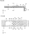
- Figs. 6A and 6B show an example inside structure of the liquid pipe 140 of the loop heat pipe 100 according to the first embodiment.
- Fig. 6A is a partial schematic plan view and Fig. 6B is a sectional view taken along line I-I in Fig. 6A.
- Fig. 6A is drawn in such a manner that the uppermost metal layer 151 of metal layers 151-156 shown in Fig. 6B is omitted.
- a porous body 150 is formed so as to be in contact with an inside pipe wall 142 (an example of a "first pipe wall") of the liquid pipe 140.
- the porous body 150 extends from the condenser 120 to the evaporator 110 along the liquid pipe 140, and a flow channel 146 of the liquid pipe 140 is formed between the porous body 150 and an outside pipe wall 143 (an example of a "second pipe wall”).
- the porous body 150 is in contact with, that is, is integrally formed with the pipe wall 142.
- the porous body 150 may be in contact with the pipe wall 142 over the full length of the porous body 150.
- the flow channel 146 is a space formed inside the liquid pipe 140 and is in contact with the pipe wall 143.
- the one flow channel 146 is formed inside (i.e., on the side of the pipe wall 142) in the liquid pipe 140 and the one flow channel 146 is formed outside (i.e., on the side of the pipe wall 143) in the liquid pipe 140.
- the porous body 150 is disposed alongside (adjacent to) the pipe wall surface (of the pipe wall 142) that is opposed to the injection inlet 141.
- the flow channel 146 is a space that is formed on the side of the pipe wall surface (of the pipe wall 143) in which the injection inlet 141 is formed.
- the injection inlet 141 communicates with the flow channel 146.
- Figs. 7A-7D are plan views showing example arrangements of bottomed holes in second to fifth metal layers 152-155, respectively.
- the cross section of the porous body 150 shown in Fig. 6B corresponds to cross sections taken along lines II-II in Figs. 7A-7D .
- the liquid pipe 140 and the porous body 150 may have a structure that six metal layers 151-156 are laid one on another.
- the metal layers 151-156 are, for example, copper layers which are superior in thermal conductivity and are joined to each other directly by solid-phase joining or the like.
- the thickness of each of the metal layers 151-156 may be about 50 to 200 ⁇ m, for example.
- the metal layers 151-156 are not limited to metal layers and may be stainless steel layers, aluminum layers, magnesium alloy layers, or the like. There are no particular limitations on the number of metal layers laid one on another; five or less metal layers or seven or more metal layers may be laid one on another.
- the Z direction is defined as the lamination direction of the metal layers 151-156
- the X direction is defined as an optional direction in the plane perpendicular to the Z direction
- the Y direction is defined as the direction perpendicular to the X direction in this plane (these definitions also apply to following similar drawings).
- no holes or grooves are formed in the first metal layer 151 (one outermost metal layer) or the sixth metal layer 156 (the other outermost metal layer).
- plural bottomed holes 152x which are recessed from the top surface to approximately the center in the thickness direction and plural bottomed holes 152y which are recessed from the bottom surface to approximately the center in the thickness direction are formed in the second metal layer 152 and in the porous body 150.
- an opening portion 152a which is part of the flow channel 146 is also formed in the metal layer 152.
- the opening portion 152a is a through-hole that penetrates through the metal layer 152 in the thickness direction (Z direction).
- Bottomed holes 152x and bottomed holes 152y are arranged alternately in the X direction, and bottomed holes 152x and a bottomed hole 152y are arranged alternately the Y direction in a plan view. Adjacent ones of bottomed holes 152x and bottomed holes 152y that are arranged alternately in the X direction overlap with each other in a plan view and the adjacent bottomed holes 152x and 152y communicate with each other in the overlap to form a pore 152z. Bottomed holes 152x and a bottomed hole 152y that are arranged alternately in the Y direction have prescribed intervals and do not overlap in a plan view.
- bottomed holes 152x and bottomed holes 152y that are arranged alternately in the Y direction do not form any pores.
- the invention is not limited to this case; bottomed holes 152x and bottomed holes 152y that are arranged alternately in the Y direction may overlap in a plan view and form pores.
- the bottomed holes 152x and 152y may be circular holes of about 100 to 300 ⁇ m in diameter, for example; however, they may have any shape such as an ellipse or a polygon.
- the depth of the bottomed holes 152x and 152y may be approximately half of that of the metal layer 152.
- the interval L 1 between adjacent bottomed holes 152x may be about 100 to 400 ⁇ m, for example.
- the interval L 2 between adjacent bottomed holes 152y may be about 100 to 400 ⁇ m, for example.
- each of the bottomed holes 152x and 152y may be tapered so that the hole width increases as the position goes from the bottom side to the opening side.
- the invention is not limited to this case; the inner wall surface of each of the bottomed holes 152x and 152y may be perpendicular to the bottom surface or may be curved so as to assume a semicircle.
- the shorter width W 3 of each pore 152z may be set at about 10 to 50 ⁇ m, for example, and the longer width W 4 of each pore 152z may be set at about 50 to 150 ⁇ m, for example.
- plural bottomed holes 153x which are recessed from the top surface to approximately the center in the thickness direction and plural bottomed holes 153y which are recessed from the bottom surface to approximately the center in the thickness direction are formed in the third metal layer 153 and in the porous body 150.
- an opening portion 153a which is part of the flow channel 146 is also formed in the metal layer 153.
- the opening portion 153a is a through-hole that penetrates through the metal layer 153 in the thickness direction (Z direction).
- rows in which only bottomed holes 153x are arranged in the X direction and rows in which only bottomed holes 153y are arranged in the X direction are arranged alternately in the Y direction.
- Adjacent ones of the bottomed holes 153x and the bottomed holes 153y in adjacent rows among the rows that are arranged alternately in the Y direction overlap with each other in a plan view and communicate with each other in the overlap to form a pore 153z.
- bottomed holes 153x and 153y that form each pore 153z are deviated from each other in the X direction.
- bottomed holes 153x and bottomed holes 153y that form pores 153z are arranged alternately in a direction that is inclined from the X direction and the Y direction.
- the shapes etc. of the bottomed holes 153x and 153y and the pores 153z may be the same as those of the bottomed holes 152x and 152y and the pores 152z.
- the bottomed holes 152y of the second metal layer 152 and the bottomed holes 153x of the third metal layer 153 are formed so as to coincide with each other in a plan view. Thus, no pores are formed in the interface between the first metal layer 152 and the second metal layer 153.
- the invention is not limited to this case; the arrangements of the bottomed holes 153x and the bottomed holes 153y in the X direction and the Y direction may be changed as appropriate so that pores are formed in the interface between the second metal layer 152 and the third metal layer 153.
- plural bottomed holes 154x which are recessed from the top surface to approximately the center in the thickness direction and plural bottomed holes 154y which are recessed from the bottom surface to approximately the center in the thickness direction are formed in the fourth metal layer 154 and in the porous body 150.
- an opening portion 154a which is part of the flow channel 146 is also formed in the metal layer 154.
- the opening portion 154a is a through-hole that penetrates through the metal layer 154 in the thickness direction (Z direction).
- Bottomed holes 154x and bottomed holes 154y are arranged alternately in the X direction, and bottomed holes 154x and bottomed holes 154y are arranged alternately the Y direction in a plan view. Adjacent ones of bottomed holes 154x and bottomed holes 154y that are arranged alternately in the X direction overlap with each other in a plan view and the adjacent bottomed holes 154x and 154y communicate with each other in the overlap to form a pore 154z. Bottomed holes 154x and a bottomed hole 154y that are arranged alternately in the Y direction have prescribed intervals and do not overlap in a plan view.
- bottomed holes 154x and a bottomed holes 154y that are arranged alternately in the Y direction do not form any pores.
- the invention is not limited to this case; bottomed holes 154x and a bottomed hole 154y that are arranged alternately in the Y direction may overlap in a plan view and form pores.
- the shapes etc. of the bottomed holes 154x and 154y and the pores 154z may be the same as those of the bottomed holes 152x and 152y and the pores 152z.
- the bottomed holes 153y of the third metal layer 153 and the bottomed holes 154x of the fourth metal layer 154 are formed so as to coincide with each other in a plan view. Thus, no pores are formed in the interface between the third metal layer 153 and the fourth metal layer 154.
- the invention is not limited to this case; the arrangements of the bottomed holes 154x and the bottomed holes 154y in the X direction and the Y direction may be changed as appropriate so that pores are formed in the interface between the third metal layer 153 and the fourth metal layer 154.
- plural bottomed holes 155x which are recessed from the top surface to approximately the center in the thickness direction and plural bottomed holes 155y which are recessed from the bottom surface to approximately the center in the thickness direction are formed in the fifth metal layer 155 and in the porous body 150.
- an opening portion 155a which is part of the flow channel 146 is also formed in the metal layer 155.
- the opening portion 155a is a through-hole that penetrates through the metal layer 155 in the thickness direction (Z direction).
- rows in which only bottomed holes 155x are arranged in the X direction and rows in which only bottomed holes 155y are arranged in the X direction are arranged alternately in the Y direction.
- Adjacent ones of the bottomed holes 155x and the bottomed holes 155y in adjacent rows among the rows that are arranged alternately in the Y direction overlap with each other in a plan view and communicate with each other in the overlap to form a pore 155z.
- bottomed holes 155x and 155y that form each pore 153z are deviated from each other in the X direction.
- bottomed holes 155x and bottomed holes 155y that form pores 155z are arranged alternately in a direction that is inclined from the X direction and the Y direction.
- the shapes etc. of the bottomed holes 155x and 155y and the pores 155z may be the same as those of the bottomed holes 152x and 152y and the pores 152z.
- the bottomed holes 154y of the fourth metal layer 152 and the bottomed holes 155x of the fifth metal layer 155 are formed so as to coincide with each other in a plan view. Thus, no pores are formed in the interface between the fourth metal layer 154 and the fifth metal layer 155.
- the invention is not limited to this case; the arrangements of the bottomed holes 155x and the bottomed holes 155y in the X direction and the Y direction may be changed as appropriate so that pores are formed in the interface between the fourth metal layer 154 and the fifth metal layer 155.
- each metal layer communicates with each other and together extend through the porous body 150 three-dimensionally.
- working fluid C expands three-dimensionally through the pores that communicate with each other.
- the porous body 150 is disposed in the liquid pipe 140 and liquid-phase working fluid C in the liquid pipe 140 is guided to the evaporator 110 by the capillary forces produced in the porous body 150.
- Part of the porous body 150 is provided in the evaporator 110.
- liquid-phase working fluid C permeates into a portion, located on the side of the liquid pipe 140, of that part of the porous body 150 which is provided in the evaporator 110.
- Resulting capillary forces acting on that portion of the working fluid C from the porous body 150 serve as pumping force for circulating the working fluid C through the loop heat pipe 100.
- the liquid pipe 140 is formed with the injection inlet 141 for injecting working fluid C, the inside of the loop heat pipe 100 is kept airtight because the injection inlet 141 is closed.
- FIG. 8 is a partial schematic plan view showing part of the liquid pipe 140 employed in the first embodiment and working fluid C flowing through it.
- the working fluid C is pulled by the capillary forces of the porous body 150 and the inside of the liquid pipe 140 is thereby filled with the working fluid C. Since unlike in the reference example not both sides (inside and outside) of the porous body 150 are provided with a flow channel, no part of the working fluid C flows into an inside flow channel and no air bubbles remain there.
- Figs. 9A-9D and Figs. 10A and 10B are sectional views showing an example manufacturing method of a loop heat pipe according to the first embodiment ( Fig. 10B is the same as Fig. 6B ).
- a metal sheet 152b having the plan-view shape shown in Fig. 4 is prepared.
- resist layers 310 and 320 are formed on the top surface and the bottom surface of the metal sheet 152b, respectively.
- the metal sheet 152b, which is to become a metal layer 152 finally, may be made of copper, stainless steel, aluminum, a magnesium alloy, or the like.
- the thickness of the metal sheet 152b may be about 50 to 200 ⁇ m, for example.
- the resist layers 310 and 320 may be made of a photosensitive dry film resist, for example.
- openings 310x for exposing selected portions of the top surface of the metal sheet 152b are formed by subjecting the resist layer 310 to exposure to light and development in a region, where to form a porous body 150, of the metal sheet 152b.
- openings 320x for exposing selected portions of the bottom surface of the metal sheet 152b are formed by subjecting the resist layer 320 to exposure to light and development in the same region of the metal sheet 152b.
- the shapes and the arrangement of the openings 310x and openings 320x are made the same as those of the bottomed holes 152x and 152y shown in Fig. 7A .
- an opening 310y for exposing a selected portion of the top surface of the metal sheet 152b is formed in a region where to form a flow channel 146. Furthermore, an opening 320y for exposing a selected portion of the bottom surface of the metal sheet 152b is formed in the region where to form a flow channel 146.
- portions, exposed through the openings 310x and 310y, of the metal sheet 152b are half-etched from the top surface side and portions, exposed through the openings 320x and 320y, of the metal sheet 152b are half-etched from the bottom surface side.
- bottomed holes 152x are formed in the metal sheet 152b on the top-surface side
- bottomed holes 152y are formed in the metal sheet 152b on the bottom-surface side
- an opening portion 152a is formed so as to penetrate through the metal sheet 152b.
- the metal sheet 152b may be half-etched using a ferric chloride solution, for example.
- solid metal layers 151 and 156 which are formed with no holes or grooves are prepared.
- Metal layers 153, 154, and 155 are formed by the same method as the metal layer 152 was formed.
- the positions of bottomed holes, pores, and openings formed in the metal layers 153, 154, and 155 are made the same as those shown in Figs. 7B-7D .
- a step shown in Fig. 10B the metal layers 151-156 are stacked one on another in the order shown in Fig. 10A and subjected to solid-phase joining through pressing and heating. As a result, adjoining metal layers are joined together directly, whereby a loop heat pipe 100 is completed which is equipped with an evaporator 110, a condenser 120, a vapor pipe 130, and a liquid pipe 140 and a porous body 150 is formed in the evaporator 110 and the liquid pipe 140.
- the porous body 150 is integrally formed with an inside pipe wall 142 of the liquid pipe 140 and a flow channel 146 as a space for guiding working fluid C to the evaporator 110 is formed between an outside pipe wall 143 and the porous body 150. After evacuating the inside of the liquid pipe 140 using a vacuum pump or the like, working fluid C is injected into the flow channel 146 through the injection inlet 141 and the injection inlet 141 is then sealed.
- the above-mentioned solid-phase joining is a method for joining target objects by heating them to soften them while keeping them in a solid phase (i.e., without melting them) and, furthermore, pressing them against each other to deform them plastically.
- a solid phase i.e., without melting them
- pores are formed in each metal layer by forming bottomed holes from both sides of the metal layer in such a manner that they communicate with each other partially, problems of the conventional pore forming method in which metal layers formed with through-holes are stacked one on another in such a manner through-holes overlap with each other can be solved. More specifically, pores having a constant size can be formed in the metal layers 152 to 155 without causing positional deviations because the pores are not affected by positional deviations that may occur when the metal layers 152 to 155 are stacked one on another or positional deviations that may occur due to expansion and contraction of the metal layers 152 to 155 when they are subjected to heating when laid one on another.
- each associated pair of bottomed holes in the two metal layers are formed so as to coincide with each other in a plan view, whereby the contact area of the two metal layers can be increased to enable strong joining.
- Fig. 11 is a sectional view showing an example liquid pipe 140 and porous body 150 employed in the second embodiment.
- the loop heat pipe according to the second embodiment is equipped with a liquid pipe 140 and a porous body 150.
- the porous body 150 is formed in the same manner as in the first embodiment and is formed to be in contact with an inside pipe wall 142 of the loop of the liquid pipe 140 in the same manner as in the first embodiment.
- opening portions 153a and 155a are larger than opening portions 152a and 154a and the side surfaces of the opening portions 153a and 155a are recessed from those of the opening portions 152a and 154a.
- the position, in the X direction, of the side surfaces of the opening portions 153a and 155a is deviated from that of the side surfaces of the opening portions 152a and 154a, whereby a groove 253 is formed in a metal layer 153 and a groove 255 is formed in a metal layer 155.
- the grooves 253 and 255 are formed so as to extend in the extension direction of the liquid pipe 140 (in the Y direction, approximately parallel with a flow channel 146).
- the second embodiment is the same as the first embodiment in the other part of the configuration.
- the second embodiment can provide the same advantages as the first embodiment.
- the grooves 253 and 255 which are formed in the wall surface of the pipe wall 143 of the flow channel 146 accelerate flow of liquid-phase working fluid C, whereby the heat transport performance can be enhanced further.
- Fig. 12 is a sectional view showing an example liquid pipe 140 and porous body 150 employed in the third embodiment.
- the loop heat pipe according to the third embodiment is equipped with a liquid pipe 140 and a porous body 150.
- the porous body 150 is formed in the same manner as in the first embodiment and is formed so as to be in contact with an inside pipe wall 142 of the loop of the liquid pipe 140 in the same manner as in the first embodiment.
- a groove 352 that is recessed from the top surface to approximately the center in the thickness direction is formed at a periphery of an opening portion 152a in the same manner as a bottomed hole 152x. That is, the top surface of a metal layer 152 is formed with the groove 352 that is continuous with a flow channel 146.
- the depth of the groove 352 may be, for example, approximately half of the thickness of the metal layer 152.
- a groove 353 that is recessed from the top surface to approximately the center in the thickness direction is formed at a periphery of an opening portion 153a in the same manner as a bottomed hole 153x. That is, the top surface of a metal layer 153 is formed with the groove 353 that is continuous with the flow channel 146.
- the depth of the groove 353 may be, for example, approximately half of the thickness of the metal layer 153.
- a groove 354 that is recessed from the top surface to approximately the center in the thickness direction is formed at a periphery of an opening portion 154a in the same manner as a bottomed hole 154x. That is, the top surface of a metal layer 154 is formed with the groove 354 that is continuous with the flow channel 146.
- the depth of the groove 354 may be, for example, approximately half of the thickness of the metal layer 154.
- a groove 355 that is recessed from the top surface to approximately the center in the thickness direction is formed at a periphery of an opening portion 155a in the same manner as a bottomed hole 155x. That is, the top surface of a metal layer 155 is formed with the groove 355 that is continuous with the flow channel 146.
- the depth of the groove 355 may be, for example, approximately half of the thickness of the metal layer 155.
- the grooves 352 to 355 are formed so as to extend in the extension direction of the liquid pipe 140 (in the Y direction, approximately parallel with the flow channel 146).
- the third embodiment is the same as the first embodiment in the other part of the configuration.
- the third embodiment can provide the same advantages as the first and second embodiments.
- the grooves 352 to 355 which are formed in the wall surface of the pipe wall 143 of the flow channel 146 accelerate flow of liquid-phase working fluid C.
- the number of grooves is larger than in the second embodiment, the heat transport performance can be enhanced even further.
- the groove 352 can be formed at the same time as the bottomed holes 152x in the following manner. That is, when the openings 310x are formed through the resist layer 310 which is used for forming the bottomed holes 152x, an opening is also formed in a region where the groove 352 is to be formed and the metal sheet 152b is half-etched. In this manner, the groove 352 can be formed at the same time as the bottomed holes 152x. Likewise, for example, the grooves 353, 354, 355 can be formed at the same time as the bottomed holes 153x, 154x, and 155x, respectively.
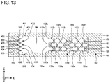
- Fig. 13 is a sectional view showing an example liquid pipe 140 and porous body 150 employed in the fourth embodiment.
- the loop heat pipe according to the fourth embodiment is equipped with a liquid pipe 140 and a porous body 150.
- the porous body 150 is formed in the same manner as in the first embodiment and is formed so as to be in contact with an inside pipe wall 142 of the loop of the liquid pipe 140 in the same manner as in the first embodiment.
- a groove 352 on the side of an outside pipe wall 143 of the liquid pipe 140, not only a groove 352 but also a groove 452 that is recessed from the bottom surface to approximately the center in the thickness direction is formed at a periphery of an opening portion 152a in the same manner as a bottomed hole 152y. That is, the bottom surface of a metal layer 152 is formed with the groove 452 that is continuous with a flow channel 146.
- the depth of the groove 452 may be, for example, approximately half of the thickness of the metal layer 152.
- a groove 353 on the side of the outside pipe wall 143, not only a groove 353 but also a groove 453 that is recessed from the bottom surface to approximately the center in the thickness direction is formed at a periphery of an opening portion 153a in the same manner as a bottomed hole 153y. That is, the bottom surface of a metal layer 153 is formed with the groove 453 that is continuous with the flow channel 146.
- the depth of the groove 453 may be, for example, approximately half of the thickness of the metal layer 153.
- a groove 354 on the side of the outside pipe wall 143, not only a groove 354 but also a groove 454 that is recessed from the bottom surface to approximately the center in the thickness direction is formed at a periphery of an opening portion 154a in the same manner as a bottomed hole 154y. That is, the bottom surface of a metal layer 154 is formed with the groove 454 that is continuous with the flow channel 146.
- the depth of the groove 454 may be, for example, approximately half of the thickness of the metal layer 154.
- a groove 355 on the side of the outside pipe wall 143, not only a groove 355 but also a groove 455 that is recessed from the bottom surface to approximately the center in the thickness direction is formed at a periphery of an opening portion 154a in the same manner as a bottomed hole 155y. That is, the bottom surface of a metal layer 155 is formed with the groove 455 that is continuous with the flow channel 146.
- the depth of the groove 455 may be, for example, approximately half of the thickness of the metal layer 155.
- the grooves 452 and 353 are connected to each other to form a groove 472.
- the grooves 453 and 354 are connected to each other to form a groove 473.
- the grooves 454 and 355 are connected to each other to form a groove 474.
- a groove 451 that is recessed from the bottom surface to approximately the center in the thickness direction is formed in a metal layer 151 so as to be continuous with the groove 352. That is, the bottom surface of the metal layer 151 is formed with the groove 451 that is continuous with the flow channel 146.
- the depth of the groove 451 may be, for example, approximately half of the thickness of the metal layer 151.
- the grooves 451 and 352 are connected to each other to form a groove 471.
- a groove 356 that is recessed from the top surface to approximately the center in the thickness direction is formed in a metal layer 156 so as to be continuous with the groove 455. That is, the top surface of the metal layer 156 is formed with the groove 356 that is continuous with the flow channel 146.
- the depth of the groove 356 may be, for example, approximately half of the thickness of the metal layer 156.
- the grooves 455 and 356 are connected to each other to form a groove 475.
- the grooves 471-475 are formed so as to extend in the extension direction of the liquid pipe 140 (in the Y direction, approximately parallel with the flow channel 146).
- the fourth embodiment is the same as the first embodiment in the other part of the configuration.
- the fourth embodiment can provide the same advantages as the first to third embodiments.
- the grooves 471 to 475 which are formed in the wall surface of the pipe wall 143 of the flow channel 146 accelerate flow of liquid-phase working fluid C.
- the number of grooves is larger than in the third embodiment, the heat transport performance can be enhanced even further.
- the groove 452 can be formed at the same time as the bottomed holes 152y in the following manner. That is, referring to Fig. 9B , when the openings 320x are formed through the resist layer 320, an opening is also formed in a region where the groove 452 is to be formed and the metal sheet 152b is half-etched. In this manner, the groove 452 can be formed at the same time as the bottomed holes 152y. For example, like the groove 452, the grooves 453, 454, 455 can be formed at the same time as the bottomed holes 153y, 154y, and 155y, respectively.
- the grooves 451 and 356 of the metal layers 151 and 156 can be formed by half-etching metal sheets using resist layers having openings in regions where the grooves 451 and 356 of the metal layers 151 and 156 are to be formed.
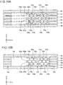
- Figs. 14A and 14B are a partial schematic plan view and a sectional view taken along line I-I in Fig. 14A , respectively, showing an example internal structure of a liquid pipe 140 of a loop heat pipe according to the fifth embodiment.
- Fig. 14A is drawn in such a manner that the uppermost one of metal layers 151-156 shown in Fig. 14B is omitted.
- the porous body 150 is formed so as to be in contact with, that is, is integrally formed with the inside pipe surface 142 of the liquid pipe 140 and the flow channel 146 is formed on the side of the outside pipe wall 143 of the liquid pipe 140.
- the porous body may include a portion that is in contact with, that is, is integrally formed with the outside pipe wall 143.
- a porous body 150a (an example of "first porous body") is formed so as to be in contact with the inside pipe wall 142 of the liquid pipe 140.
- the porous body 150a has the same sectional structure as the above-described porous body 150. That is, as shown Fig. 14B , the porous body 150a is formed so as to span metal layers 152 to 155.
- another porous body 150b (an example of "second porous body”) is formed so as to be in contact with the outside pipe wall 143 of the liquid pipe 140.
- the porous body 150b is opposed to the porous body 150a and extends along the liquid pipe 140 from the condenser 120 to a position in the vicinity of the injection inlet 141.
- the porous body 150b has the same sectional structure as the above-described porous body 150. That is, as shown in Fig. 14B , the porous body 150b is formed so as to span the metal layers 152 to 155.
- porous bodies 150c (an example of "third porous bodies”) that connect the porous bodies 150a and 150b are formed between the end, on the side of the injection inlet 141, of the porous body 150b and the porous body 150a.
- the porous bodies 150c are formed in only part of the metal layers 152 to 155; for example, the porous bodies 150c are formed in only the respective metal layers 152 and 155 and openings 153a and 154a are formed in the respective metal layers 153 and 154.
- the porous bodies 150c are formed between the porous bodies 150a and 150b. One ends of the porous bodies 150c are connected to the porous body 150a and their other ends are connected to the porous body 150b.
- a portion, between the porous bodies 150c and the condenser 120, of the flow channel 146 of the liquid pipe 140 is formed between the porous bodies 150a and 150b.
- the opening 153a and 154a serve as the flow channel 146.
- a portion, between the porous bodies 150c and the evaporator 110, of the flow channel 146 of the liquid pipe 140 is formed between the porous body 150a and the outside pipe wall 143.
- the flow channel 146 of the liquid pipe 140 is a space for guiding working fluid C to the evaporator 110.
- the above-described fifth embodiment can suppress a phenomenon that air bubbles remain after injection of working fluid C.
- porous body 150 is formed so as to extend from the condenser 120 to the evaporator 110 such that part of it is in contact with the outside pipe wall 143 while bypassing the injection inlet 141 as long as at least the porous body 150 is deviated to the side of the inside pipe wall 142 of the liquid pipe 140 and can guide liquid-phase working fluid C from the condenser 120 to the evaporator 110.
- bottomed holes may be formed in the metal layer 151 or 156 in the region where the porous body 150 is formed. Bottomed holes may be formed in a portion, exposed to the flow channel 146, of the metal layer 151 or 156. Forming bottomed holes also in the metal layer 151 or 156 makes it possible to enhance the heat transport performance even further.
Landscapes
- Engineering & Computer Science (AREA)
- Life Sciences & Earth Sciences (AREA)
- Sustainable Development (AREA)
- Physics & Mathematics (AREA)
- Thermal Sciences (AREA)
- Mechanical Engineering (AREA)
- General Engineering & Computer Science (AREA)
- Cooling Or The Like Of Semiconductors Or Solid State Devices (AREA)
Abstract
Description
- The present disclosure relates to a loop heat pipe.
- Heat pipes are known as devices for cooling a heat generation component such as a CPU (central processing unit) that is installed in an electronic device. The heat pipe is a device that transports heat utilizing phase transition of a working fluid.
- An example heat pipe is a loop heat pipe that is equipped with an evaporator that evaporates working fluid by heat generated by a heat generation component and a condenser that condenses evaporated working fluid by cooling it, and in which the evaporator and the condenser are connected to each other by a liquid pipe and a vapor pipe that form a loop-shaped flow channel. In loop heat pipes, the working fluid flows through a loop-shaped flow channel in one direction.
- A porous body is provided in a liquid pipe of a loop heat pipe, and working fluid in the liquid pipe is guided to the evaporator by capillary forces generated in the porous body, whereby a reverse flow of vapor from the evaporator to the liquid pipe is suppressed. A number of pores are formed in the porous body. Pores are formed by laying, one on another, metal layers through each of which through-holes are formed in such a manner that adjacent through-holes overlap with each other. Refer to Japanese Patent No.
6,146,484 - However, the loop heat pipe disclosed in Japanese Patent No.
6,146,484 - Certain embodiments provide a loop heat pipe.
- The loop heat pipe comprises:
- an evaporator configured to evaporate working fluid;
- a condenser configured to condense the working fluid;
- a liquid pipe which connects the evaporator and the condenser and has a first pipe wall and a second pipe wall which is opposed to the first pipe wall;
- a porous body which is provided in the liquid pipe and is configured to guide the working fluid condensed by the condenser to the evaporator;
- a flow channel which is a space that is formed in the liquid pipe and guides the working fluid condensed by the condenser to the evaporator; and
- a vapor pipe which connects the evaporator and the condenser and forms a loop together with the liquid pipe.
- The porous body is disposed to be in contact with the first pipe wall.
-
-
Fig. 1 is a schematic plan view of a loop heat pipe as a reference example; -
Figs. 2A and 2B are a partial schematic plan view and a sectional view taken along line I-I inFig. 2A , respectively, showing an example internal structure of a liquid pipe of the loop heat pipe as the reference example; -
Fig. 3 is a partial schematic plan view showing part of the liquid pipe employed in the reference example and working fluid flowing through it; -
Fig. 4 is a schematic plan view showing a loop heat pipe according to a first embodiment; -
Fig. 5 is a sectional view showing an evaporator and its neighborhood of the loop heat pipe according to the first embodiment; -
Figs. 6A and 6B are a partial schematic plan view and a sectional view taken along line I-I inFig. 6A , respectively, showing an example internal structure of a liquid pipe of the loop heat pipe according to the first embodiment; -
Figs. 7A-7D are plan views showing example arrangements of bottomed holes in the second, third, fourth, and fifth metal layers, respectively; -
Fig. 8 is a partial schematic plan view showing part of the liquid pipe employed in the first embodiment and working fluid flowing through it; -
Figs. 9A-9D are a first set of sectional views showing an example manufacturing method of the loop heat pipe according to the first embodiment; -
Figs. 10A and 10B are a second set of sectional views showing the example manufacturing method of the loop heat pipe according to the first embodiment; -
Fig. 11 is a sectional view showing an example liquid pipe and porous body employed in a second embodiment; -
Fig. 12 is a sectional view showing an example liquid pipe and porous body employed in a third embodiment; -
Fig. 13 is a sectional view showing an example liquid pipe and porous body employed in a fourth embodiment; and -
Figs. 14A and 14B are a partial schematic plan view and a sectional view taken along line I-I inFig. 14A , respectively, showing an example internal structure of a liquid pipe of a loop heat pipe according to a fifth embodiment. - The present inventors diligently studied to find a reason why there may occur a case that sufficiently high heat transport performance cannot be obtained. Detailed analyses of the inventors have found that air bubbles exist in a flow channel that should be filled with liquid-phase working fluid and obstruct flow of the liquid-phase working fluid. It has also been found that one reason of the above problem is a phenomenon that a porous body provided in a liquid pipe obstructs movement of working fluid in the liquid pipe during charging of working fluid. These new pieces of knowledge will be described below using a reference example.
-
Fig. 1 is a schematic plan view of a loop heat pipe as a reference example. - As shown in
Fig. 1 , aloop heat pipe 900 of the reference example is equipped with anevaporator 910, acondenser 920, avapor pipe 930, and aliquid pipe 940. - In the
loop heat pipe 900, theevaporator 910 is configured to generate vapor Cv by evaporating working fluid C. Thecondenser 920 is configured to condense the vapor Cv. Theevaporator 910 and thecondenser 920 are connected to each other by thevapor pipe 930 and theliquid pipe 940, and thevapor pipe 930 and theliquid pipe 940 form a flow channel that is a loop through which the working fluid C or the vapor Cv flows. - The
liquid pipe 940 is formed with aninjection inlet 941 through which working fluid C is injected. Theinjection inlet 941 is sealed after injection of working fluid C. -
Figs. 2A and 2B show an example inside structure of theliquid pipe 940 of the loop heat pipe as the reference example.Fig. 2A is a partial schematic plan view andFig. 2B is a sectional view taken along line I-I inFig. 2A. Fig. 2A is drawn in such a manner that the uppermost one of metal layers shown inFig. 2B is omitted. - As shown in
Figs. 2A and 2B , a prop-likeporous body 950 is disposed at the center, in a plan view, of theliquid pipe 940. Theporous body 950 extends along theliquid pipe 940 from thecondenser 920 to theevaporator 910, and the flow channel of theliquid pipe 940 is divided into two channels, that is, anoutside flow channel 946 which is formed outside theporous body 950 and aninside flow channel 947 which is formed inside theporous body 950. Theinjection inlet 941 communicates with theoutside flow channel 946. - Behavior of working fluid C that has been injected into the
liquid pipe 940 employed in the reference example will be described below.Fig. 3 is a partial schematic plan view showing part of theliquid pipe 940 employed in the reference example and working fluid C flowing through it. - Liquid-phase working fluid C that has been injected into the
liquid pipe 940 through theinjection inlet 941 spreads over theoutside flow channel 946 and theoutside flow channel 946 is filled with working fluid C. Working fluid C also flows into theinside flow channel 947 while permeating through theporous body 950. However, since theporous body 950 obstructs movement of working fluid C to not a small extent, working fluid C flows into portions of theinside flow channel 947 discontinuously. As a result, air bubbles 948 are prone to remain in theinside flow channel 947, particularly in the vicinity of abent portion 945 of theliquid pipe 940. - The air bubbles 948 existing in the
liquid pipe 940 obstruct flow of liquid-phase working fluid C, possibly resulting in unexpected reduction in heat transport performance. Furthermore, the air bubbles 948 may cause theliquid pipe 940 to swell when theloop heat pipe 900 receives heat. Such swelling may lower the mechanical strength of theliquid pipe 940. - Embodiments of the invention will be hereinafter described in a specific manner with reference to the accompanying drawings. In this specification, constituent elements having substantially the same function and structure will be given the same reference symbol and a redundant description therefor may be omitted.
- A first embodiment will be described below which relates to a loop heat pipe.
-
Fig. 4 is a schematic plan view showing aloop heat pipe 100 according to the first embodiment. - As shown in
Fig. 4 , theloop heat pipe 100 according to the first embodiment is equipped with anevaporator 110, acondenser 120, avapor pipe 130, and aliquid pipe 140. Theloop heat pipe 100 can be housed in a mobileelectronic device 102 such as a smartphone or a tablet terminal. - In the
loop heat pipe 100, theevaporator 110 is configured to generate vapor Cv by evaporating working fluid C. Thecondenser 120 is configured to condense the vapor Cv. Theevaporator 110 and thecondenser 120 are connected to each other by thevapor pipe 130 and theliquid pipe 140, and thevapor pipe 130 and the liquid pipe140 form a flow channel that is a loop through which the working fluid C or the vapor Cv flows. - The
liquid pipe 140 is formed with aninjection inlet 141 through which working fluid C is injected. Theinjection inlet 141 is closed after injection of working fluid C. -
Fig. 5 is a sectional view showing theevaporator 110 and its neighborhood of theloop heat pipe 100 according to the first embodiment. As shown inFigs. 4 and5 , theevaporator 110 is formed with four through-holes 110x, for example. Theevaporator 110 is fixed to acircuit board 10 by insertingbolts 15 through the respective through-holes 110x and engagingnuts 16 with them from the side of the bottom surface of thecircuit board 10. - A
heat generation component 12 such as a CPU is mounted on thecircuit board 10 viabumps 11, and the top surface of theheat generation component 12 is in close contact with the bottom surface of theevaporator 110. The working fluid C in theevaporator 110 is evaporated by heat generated by theheat generation component 12 and vapor Cv is thereby generated. - As shown in
Fig. 4 , vapor Cv generated by theevaporator 110 is guided to thecondenser 120 through thevapor pipe 130 and condensed in thecondenser 120. As a result, heat that was generated by theheat generation component 12 is moved to thecondenser 120, whereby temperature increase of theheat generation component 12 is suppressed. Working fluid C produced by thecondenser 120 through condensing process passes through theliquid pipe 140 and is thereby guided to theevaporator 110. For example, the widths W1 and W2 of thevapor pipe 130 and theliquid pipe 140 may be set at about 8 mm and 6 mm, respectively. However, the widths W1 and W2 of thevapor pipe 130 and theliquid pipe 140 are not limited to these values and may be identical, for example. - There are no particular limitations on the kind of the working fluid C. To cool the
heat generation component 12 efficiently using heat of evaporation, it is preferable to use a fluid having a high saturated vapor pressure and a large heat of evaporation. Examples of such a fluid are ammonia, water, chlorofluorocarbon, alcohol, and acetone. - As shown in
Fig. 6B , each of theevaporator 110, thecondenser 120, thevapor pipe 130, and theliquid pipe 140 may have, for example a structure in which plural metal layers are stacked one on another. The metal layers are, for example, copper layers which are superior in heat conductivity and are joined to each other directly by solid-phase joining or the like. The thickness of each metal layer may be about 50 to 200 µm, for example. - The meal layers are not limited to copper layers and may be stainless steel layers, aluminum layers, magnesium alloy layers, or the like. There are no particular limitations on the number of metal layers stacked one on another.
-
Figs. 6A and 6B show an example inside structure of theliquid pipe 140 of theloop heat pipe 100 according to the first embodiment.Fig. 6A is a partial schematic plan view andFig. 6B is a sectional view taken along line I-I inFig. 6A. Fig. 6A is drawn in such a manner that theuppermost metal layer 151 of metal layers 151-156 shown inFig. 6B is omitted. - As shown in
Figs. 6A and 6B , aporous body 150 is formed so as to be in contact with an inside pipe wall 142 (an example of a "first pipe wall") of theliquid pipe 140. Theporous body 150 extends from thecondenser 120 to theevaporator 110 along theliquid pipe 140, and aflow channel 146 of theliquid pipe 140 is formed between theporous body 150 and an outside pipe wall 143 (an example of a "second pipe wall"). Theporous body 150 is in contact with, that is, is integrally formed with thepipe wall 142. Theporous body 150 may be in contact with thepipe wall 142 over the full length of theporous body 150. Theflow channel 146 is a space formed inside theliquid pipe 140 and is in contact with thepipe wall 143. - As described above, the one
flow channel 146 is formed inside (i.e., on the side of the pipe wall 142) in theliquid pipe 140 and the oneflow channel 146 is formed outside (i.e., on the side of the pipe wall 143) in theliquid pipe 140. In other words, theporous body 150 is disposed alongside (adjacent to) the pipe wall surface (of the pipe wall 142) that is opposed to theinjection inlet 141. Theflow channel 146 is a space that is formed on the side of the pipe wall surface (of the pipe wall 143) in which theinjection inlet 141 is formed. Theinjection inlet 141 communicates with theflow channel 146. - The structures of the
liquid pipe 140 and theporous body 150 will be described below.Figs. 7A-7D are plan views showing example arrangements of bottomed holes in second to fifth metal layers 152-155, respectively. The cross section of theporous body 150 shown inFig. 6B corresponds to cross sections taken along lines II-II inFigs. 7A-7D . - For example, the
liquid pipe 140 and theporous body 150 may have a structure that six metal layers 151-156 are laid one on another. The metal layers 151-156 are, for example, copper layers which are superior in thermal conductivity and are joined to each other directly by solid-phase joining or the like. The thickness of each of the metal layers 151-156 may be about 50 to 200 µm, for example. The metal layers 151-156 are not limited to metal layers and may be stainless steel layers, aluminum layers, magnesium alloy layers, or the like. There are no particular limitations on the number of metal layers laid one on another; five or less metal layers or seven or more metal layers may be laid one on another. - In
Figs. 6B and7A-7D , the Z direction is defined as the lamination direction of the metal layers 151-156, the X direction is defined as an optional direction in the plane perpendicular to the Z direction, and the Y direction is defined as the direction perpendicular to the X direction in this plane (these definitions also apply to following similar drawings). - In the
liquid pipe 140 and theporous body 150, no holes or grooves are formed in the first metal layer 151 (one outermost metal layer) or the sixth metal layer 156 (the other outermost metal layer). On the other hand, as shown inFigs. 6B and7A , plural bottomedholes 152x which are recessed from the top surface to approximately the center in the thickness direction and plural bottomedholes 152y which are recessed from the bottom surface to approximately the center in the thickness direction are formed in thesecond metal layer 152 and in theporous body 150. As shown inFig. 6B , anopening portion 152a which is part of theflow channel 146 is also formed in themetal layer 152. Theopening portion 152a is a through-hole that penetrates through themetal layer 152 in the thickness direction (Z direction). - Bottomed
holes 152x and bottomedholes 152y are arranged alternately in the X direction, and bottomedholes 152x and a bottomedhole 152y are arranged alternately the Y direction in a plan view. Adjacent ones of bottomedholes 152x and bottomedholes 152y that are arranged alternately in the X direction overlap with each other in a plan view and the adjacent bottomedholes pore 152z. Bottomedholes 152x and a bottomedhole 152y that are arranged alternately in the Y direction have prescribed intervals and do not overlap in a plan view. Thus, bottomedholes 152x and bottomedholes 152y that are arranged alternately in the Y direction do not form any pores. However, the invention is not limited to this case; bottomedholes 152x and bottomedholes 152y that are arranged alternately in the Y direction may overlap in a plan view and form pores. - The bottomed
holes holes metal layer 152. The interval L1 between adjacent bottomedholes 152x may be about 100 to 400 µm, for example. The interval L2 between adjacent bottomedholes 152y may be about 100 to 400 µm, for example. - The inner wall surface of each of the bottomed
holes holes pore 152z may be set at about 10 to 50 µm, for example, and the longer width W4 of eachpore 152z may be set at about 50 to 150 µm, for example. - As shown in
Figs. 6B and7B , plural bottomedholes 153x which are recessed from the top surface to approximately the center in the thickness direction and plural bottomedholes 153y which are recessed from the bottom surface to approximately the center in the thickness direction are formed in thethird metal layer 153 and in theporous body 150. As shown inFig. 6B , anopening portion 153a which is part of theflow channel 146 is also formed in themetal layer 153. Theopening portion 153a is a through-hole that penetrates through themetal layer 153 in the thickness direction (Z direction). - In the
third metal layer 153, rows in which only bottomedholes 153x are arranged in the X direction and rows in which only bottomedholes 153y are arranged in the X direction are arranged alternately in the Y direction. Adjacent ones of the bottomedholes 153x and the bottomedholes 153y in adjacent rows among the rows that are arranged alternately in the Y direction overlap with each other in a plan view and communicate with each other in the overlap to form apore 153z. - However, the center positions of bottomed
holes pore 153z are deviated from each other in the X direction. In other words, bottomedholes 153x and bottomedholes 153y that form pores 153z are arranged alternately in a direction that is inclined from the X direction and the Y direction. For example, the shapes etc. of the bottomedholes pores 153z may be the same as those of the bottomedholes pores 152z. - The bottomed
holes 152y of thesecond metal layer 152 and the bottomedholes 153x of thethird metal layer 153 are formed so as to coincide with each other in a plan view. Thus, no pores are formed in the interface between thefirst metal layer 152 and thesecond metal layer 153. However, the invention is not limited to this case; the arrangements of the bottomedholes 153x and the bottomedholes 153y in the X direction and the Y direction may be changed as appropriate so that pores are formed in the interface between thesecond metal layer 152 and thethird metal layer 153. - As shown in
Figs. 6B and7C , plural bottomedholes 154x which are recessed from the top surface to approximately the center in the thickness direction and plural bottomedholes 154y which are recessed from the bottom surface to approximately the center in the thickness direction are formed in thefourth metal layer 154 and in theporous body 150. As shown inFig. 6B , anopening portion 154a which is part of theflow channel 146 is also formed in themetal layer 154. Theopening portion 154a is a through-hole that penetrates through themetal layer 154 in the thickness direction (Z direction). - Bottomed
holes 154x and bottomedholes 154y are arranged alternately in the X direction, and bottomedholes 154x and bottomedholes 154y are arranged alternately the Y direction in a plan view. Adjacent ones of bottomedholes 154x and bottomedholes 154y that are arranged alternately in the X direction overlap with each other in a plan view and the adjacent bottomedholes pore 154z. Bottomedholes 154x and a bottomedhole 154y that are arranged alternately in the Y direction have prescribed intervals and do not overlap in a plan view. Thus, bottomedholes 154x and a bottomed holes 154y that are arranged alternately in the Y direction do not form any pores. However, the invention is not limited to this case; bottomedholes 154x and a bottomedhole 154y that are arranged alternately in the Y direction may overlap in a plan view and form pores. For example, the shapes etc. of the bottomedholes pores 154z may be the same as those of the bottomedholes pores 152z. - The bottomed
holes 153y of thethird metal layer 153 and the bottomedholes 154x of thefourth metal layer 154 are formed so as to coincide with each other in a plan view. Thus, no pores are formed in the interface between thethird metal layer 153 and thefourth metal layer 154. However, the invention is not limited to this case; the arrangements of the bottomedholes 154x and the bottomedholes 154y in the X direction and the Y direction may be changed as appropriate so that pores are formed in the interface between thethird metal layer 153 and thefourth metal layer 154. - As shown in
Figs. 6B and7D , plural bottomedholes 155x which are recessed from the top surface to approximately the center in the thickness direction and plural bottomedholes 155y which are recessed from the bottom surface to approximately the center in the thickness direction are formed in thefifth metal layer 155 and in theporous body 150. As shown inFig. 6B , anopening portion 155a which is part of theflow channel 146 is also formed in themetal layer 155. Theopening portion 155a is a through-hole that penetrates through themetal layer 155 in the thickness direction (Z direction). - In the
fifth metal layer 155, rows in which only bottomedholes 155x are arranged in the X direction and rows in which only bottomedholes 155y are arranged in the X direction are arranged alternately in the Y direction. Adjacent ones of the bottomedholes 155x and the bottomedholes 155y in adjacent rows among the rows that are arranged alternately in the Y direction overlap with each other in a plan view and communicate with each other in the overlap to form apore 155z. - However, the center positions of bottomed
holes pore 153z are deviated from each other in the X direction. In other words, bottomedholes 155x and bottomedholes 155y that form pores 155z are arranged alternately in a direction that is inclined from the X direction and the Y direction. For example, the shapes etc. of the bottomedholes pores 155z may be the same as those of the bottomedholes pores 152z. - The bottomed
holes 154y of thefourth metal layer 152 and the bottomedholes 155x of thefifth metal layer 155 are formed so as to coincide with each other in a plan view. Thus, no pores are formed in the interface between thefourth metal layer 154 and thefifth metal layer 155. However, the invention is not limited to this case; the arrangements of the bottomedholes 155x and the bottomedholes 155y in the X direction and the Y direction may be changed as appropriate so that pores are formed in the interface between thefourth metal layer 154 and thefifth metal layer 155. - The pores formed in each metal layer communicate with each other and together extend through the
porous body 150 three-dimensionally. As a result, because of capillary forces, working fluid C expands three-dimensionally through the pores that communicate with each other. - As described above, the
porous body 150 is disposed in theliquid pipe 140 and liquid-phase working fluid C in theliquid pipe 140 is guided to theevaporator 110 by the capillary forces produced in theporous body 150. - As a result, even if vapor Cv is forced to flow reversely into the
liquid pipe 140 due to, for example, heat leakage from theevaporator 110, the capillary forces acting on liquid-phase working fluid C in theporous body 150 can push back the vapor Cv. A reverse flow of the vapor Cv can thus be prevented. - Part of the
porous body 150 is provided in theevaporator 110. In theevaporator 110, liquid-phase working fluid C permeates into a portion, located on the side of theliquid pipe 140, of that part of theporous body 150 which is provided in theevaporator 110. Resulting capillary forces acting on that portion of the working fluid C from theporous body 150 serve as pumping force for circulating the working fluid C through theloop heat pipe 100. - Since the capillary forces counter the vapor Cv existing in the
evaporator 110, a reverse flow of the vapor Cv into theliquid pipe 140 can be suppressed. - Although the
liquid pipe 140 is formed with theinjection inlet 141 for injecting working fluid C, the inside of theloop heat pipe 100 is kept airtight because theinjection inlet 141 is closed. - How working fluid C injected into the
liquid pipe 140 behaves in the first embodiment will now be described.Fig. 8 is a partial schematic plan view showing part of theliquid pipe 140 employed in the first embodiment and working fluid C flowing through it. - Liquid-phase working fluid C that has been injected into the
liquid pipe 146 through theinjection inlet 141 spreads over theflow channel 146 and theflow channel 146 is filled with working fluid C. The working fluid C is pulled by the capillary forces of theporous body 150 and the inside of theliquid pipe 140 is thereby filled with the working fluid C. Since unlike in the reference example not both sides (inside and outside) of theporous body 150 are provided with a flow channel, no part of the working fluid C flows into an inside flow channel and no air bubbles remain there. - As a result, in the
loop heat pipe 100 according to the first embodiment, a phenomenon that air bubbles produced in theflow channel 146 obstruct flow of liquid-phase working fluid C can be suppressed, whereby superior heat transport performance can be obtained. Furthermore, swelling of theliquid pipe 140 due to air bubbles can be suppressed. - Next, a manufacturing method of a loop heat pipe according to the first embodiment, mainly a manufacturing method of a porous body, will be described below.
Figs. 9A-9D andFigs. 10A and 10B are sectional views showing an example manufacturing method of a loop heat pipe according to the first embodiment (Fig. 10B is the same asFig. 6B ). - First, in a step shown in
Fig. 9A , ametal sheet 152b having the plan-view shape shown inFig. 4 is prepared. Then resistlayers metal sheet 152b, respectively. Themetal sheet 152b, which is to become ametal layer 152 finally, may be made of copper, stainless steel, aluminum, a magnesium alloy, or the like. The thickness of themetal sheet 152b may be about 50 to 200 µm, for example. The resist layers 310 and 320 may be made of a photosensitive dry film resist, for example. - Then, in a step shown in
Fig. 9B ,openings 310x for exposing selected portions of the top surface of themetal sheet 152b are formed by subjecting the resistlayer 310 to exposure to light and development in a region, where to form aporous body 150, of themetal sheet 152b. Furthermore,openings 320x for exposing selected portions of the bottom surface of themetal sheet 152b are formed by subjecting the resistlayer 320 to exposure to light and development in the same region of themetal sheet 152b. The shapes and the arrangement of theopenings 310x andopenings 320x are made the same as those of the bottomedholes Fig. 7A . - As shown in
Fig. 9B , when the resistlayer 310 is subjected to exposure to light and development, anopening 310y for exposing a selected portion of the top surface of themetal sheet 152b is formed in a region where to form aflow channel 146. Furthermore, anopening 320y for exposing a selected portion of the bottom surface of themetal sheet 152b is formed in the region where to form aflow channel 146. - Then, in a step shown in
Fig. 9C , portions, exposed through theopenings metal sheet 152b are half-etched from the top surface side and portions, exposed through theopenings metal sheet 152b are half-etched from the bottom surface side. As a result, bottomedholes 152x are formed in themetal sheet 152b on the top-surface side, bottomedholes 152y are formed in themetal sheet 152b on the bottom-surface side, and anopening portion 152a is formed so as to penetrate through themetal sheet 152b. Since adjacent ones of theopenings 310x (front side) and theopenings 310y (back side) which are arranged alternately in the X direction overlap with each other in a plan view, they communicate with each other in the overlap and form apore 152z. Themetal sheet 152b may be half-etched using a ferric chloride solution, for example. - Then, in a step shown in
Fig. 9D , the resistlayers metal layer 152 is thus completed. - Subsequently, in a step shown in
Fig. 10A ,solid metal layers metal layer 152 was formed. The positions of bottomed holes, pores, and openings formed in the metal layers 153, 154, and 155 are made the same as those shown inFigs. 7B-7D . - Subsequently, in a step shown in
Fig. 10B , the metal layers 151-156 are stacked one on another in the order shown inFig. 10A and subjected to solid-phase joining through pressing and heating. As a result, adjoining metal layers are joined together directly, whereby aloop heat pipe 100 is completed which is equipped with anevaporator 110, acondenser 120, avapor pipe 130, and aliquid pipe 140 and aporous body 150 is formed in theevaporator 110 and theliquid pipe 140. Theporous body 150 is integrally formed with aninside pipe wall 142 of theliquid pipe 140 and aflow channel 146 as a space for guiding working fluid C to theevaporator 110 is formed between anoutside pipe wall 143 and theporous body 150. After evacuating the inside of theliquid pipe 140 using a vacuum pump or the like, working fluid C is injected into theflow channel 146 through theinjection inlet 141 and theinjection inlet 141 is then sealed. - The above-mentioned solid-phase joining is a method for joining target objects by heating them to soften them while keeping them in a solid phase (i.e., without melting them) and, furthermore, pressing them against each other to deform them plastically. To allow adjoining metal layers to be joined together satisfactorily by solid-phase joining, it is preferable that all of the metal layers 151-156 be made of the same material.
- Since as described above pores are formed in each metal layer by forming bottomed holes from both sides of the metal layer in such a manner that they communicate with each other partially, problems of the conventional pore forming method in which metal layers formed with through-holes are stacked one on another in such a manner through-holes overlap with each other can be solved. More specifically, pores having a constant size can be formed in the metal layers 152 to 155 without causing positional deviations because the pores are not affected by positional deviations that may occur when the metal layers 152 to 155 are stacked one on another or positional deviations that may occur due to expansion and contraction of the metal layers 152 to 155 when they are subjected to heating when laid one on another.
- As a result, reduction of capillary forces of the pores due to a variation of their sizes and hence the effect of suppressing a reverse flow of vapor Cv from the
evaporator 110 to theliquid pipe 140 can be obtained stably. - At the interface between two metal layers, each associated pair of bottomed holes in the two metal layers are formed so as to coincide with each other in a plan view, whereby the contact area of the two metal layers can be increased to enable strong joining.
- Next, a second embodiment will be described which is different from the first embodiment in the shape of the
outside pipe wall 143 of theliquid pipe 140.Fig. 11 is a sectional view showing an exampleliquid pipe 140 andporous body 150 employed in the second embodiment. - Like the
loop heat pipe 100 according to the first embodiment, the loop heat pipe according to the second embodiment is equipped with aliquid pipe 140 and aporous body 150. Theporous body 150 is formed in the same manner as in the first embodiment and is formed to be in contact with aninside pipe wall 142 of the loop of theliquid pipe 140 in the same manner as in the first embodiment. - On the other hand, as shown in
Fig. 11 , on the side of anoutside pipe wall 143 of theliquid pipe 140, openingportions portions portions portions outside pipe wall 143, the position, in the X direction, of the side surfaces of the openingportions portions groove 253 is formed in ametal layer 153 and agroove 255 is formed in ametal layer 155. For example, thegrooves - The second embodiment is the same as the first embodiment in the other part of the configuration.
- The second embodiment can provide the same advantages as the first embodiment. In addition, the
grooves pipe wall 143 of theflow channel 146 accelerate flow of liquid-phase working fluid C, whereby the heat transport performance can be enhanced further. - Next, a third embodiment will be described which is different from the first and second embodiments in the shape of the
outside pipe wall 143 of theliquid pipe 140.Fig. 12 is a sectional view showing an exampleliquid pipe 140 andporous body 150 employed in the third embodiment. - Like the
loop heat pipe 100 according to the first embodiment, the loop heat pipe according to the third embodiment is equipped with aliquid pipe 140 and aporous body 150. Theporous body 150 is formed in the same manner as in the first embodiment and is formed so as to be in contact with aninside pipe wall 142 of the loop of theliquid pipe 140 in the same manner as in the first embodiment. - On the other hand, as shown in
Fig. 12 , on the side of anoutside pipe wall 143 of theliquid pipe 140, agroove 352 that is recessed from the top surface to approximately the center in the thickness direction is formed at a periphery of anopening portion 152a in the same manner as a bottomedhole 152x. That is, the top surface of ametal layer 152 is formed with thegroove 352 that is continuous with aflow channel 146. The depth of thegroove 352 may be, for example, approximately half of the thickness of themetal layer 152. - As shown in
Fig. 12 , on the side of theoutside pipe wall 143, agroove 353 that is recessed from the top surface to approximately the center in the thickness direction is formed at a periphery of anopening portion 153a in the same manner as a bottomedhole 153x. That is, the top surface of ametal layer 153 is formed with thegroove 353 that is continuous with theflow channel 146. The depth of thegroove 353 may be, for example, approximately half of the thickness of themetal layer 153. - As shown in
Fig. 12 , on the side of theoutside pipe wall 143, agroove 354 that is recessed from the top surface to approximately the center in the thickness direction is formed at a periphery of anopening portion 154a in the same manner as a bottomedhole 154x. That is, the top surface of ametal layer 154 is formed with thegroove 354 that is continuous with theflow channel 146. The depth of thegroove 354 may be, for example, approximately half of the thickness of themetal layer 154. - As shown in
Fig. 12 , on the side of theoutside pipe wall 143, agroove 355 that is recessed from the top surface to approximately the center in the thickness direction is formed at a periphery of anopening portion 155a in the same manner as a bottomedhole 155x. That is, the top surface of ametal layer 155 is formed with thegroove 355 that is continuous with theflow channel 146. The depth of thegroove 355 may be, for example, approximately half of the thickness of themetal layer 155. - For example, the
grooves 352 to 355 are formed so as to extend in the extension direction of the liquid pipe 140 (in the Y direction, approximately parallel with the flow channel 146). - The third embodiment is the same as the first embodiment in the other part of the configuration.
- The third embodiment can provide the same advantages as the first and second embodiments. In addition, the
grooves 352 to 355 which are formed in the wall surface of thepipe wall 143 of theflow channel 146 accelerate flow of liquid-phase working fluid C. With an additional feature that the number of grooves is larger than in the second embodiment, the heat transport performance can be enhanced even further. - For example, the
groove 352 can be formed at the same time as the bottomedholes 152x in the following manner. That is, when theopenings 310x are formed through the resistlayer 310 which is used for forming the bottomedholes 152x, an opening is also formed in a region where thegroove 352 is to be formed and themetal sheet 152b is half-etched. In this manner, thegroove 352 can be formed at the same time as the bottomedholes 152x. Likewise, for example, thegrooves holes - Next, a fourth embodiment will be described which is different from the first to third embodiments in the shape of the
outside pipe wall 143 of theliquid pipe 140.Fig. 13 is a sectional view showing an exampleliquid pipe 140 andporous body 150 employed in the fourth embodiment. - Like the
loop heat pipe 100 according to the first embodiment, the loop heat pipe according to the fourth embodiment is equipped with aliquid pipe 140 and aporous body 150. Theporous body 150 is formed in the same manner as in the first embodiment and is formed so as to be in contact with aninside pipe wall 142 of the loop of theliquid pipe 140 in the same manner as in the first embodiment. - On the other hand, as shown in
Fig. 13 , on the side of anoutside pipe wall 143 of theliquid pipe 140, not only agroove 352 but also agroove 452 that is recessed from the bottom surface to approximately the center in the thickness direction is formed at a periphery of anopening portion 152a in the same manner as a bottomedhole 152y. That is, the bottom surface of ametal layer 152 is formed with thegroove 452 that is continuous with aflow channel 146. The depth of thegroove 452 may be, for example, approximately half of the thickness of themetal layer 152. - As shown in
Fig. 13 , on the side of theoutside pipe wall 143, not only agroove 353 but also agroove 453 that is recessed from the bottom surface to approximately the center in the thickness direction is formed at a periphery of anopening portion 153a in the same manner as a bottomedhole 153y. That is, the bottom surface of ametal layer 153 is formed with thegroove 453 that is continuous with theflow channel 146. The depth of thegroove 453 may be, for example, approximately half of the thickness of themetal layer 153. - As shown in
Fig. 13 , on the side of theoutside pipe wall 143, not only agroove 354 but also agroove 454 that is recessed from the bottom surface to approximately the center in the thickness direction is formed at a periphery of anopening portion 154a in the same manner as a bottomedhole 154y. That is, the bottom surface of ametal layer 154 is formed with thegroove 454 that is continuous with theflow channel 146. The depth of thegroove 454 may be, for example, approximately half of the thickness of themetal layer 154. - As shown in
Fig. 13 , on the side of theoutside pipe wall 143, not only agroove 355 but also agroove 455 that is recessed from the bottom surface to approximately the center in the thickness direction is formed at a periphery of anopening portion 154a in the same manner as a bottomedhole 155y. That is, the bottom surface of ametal layer 155 is formed with thegroove 455 that is continuous with theflow channel 146. The depth of thegroove 455 may be, for example, approximately half of the thickness of themetal layer 155. - The
grooves groove 472. Thegrooves groove 473. Thegrooves groove 474. - Furthermore, as shown in
Fig. 13 , on the side of theoutside pipe wall 143, agroove 451 that is recessed from the bottom surface to approximately the center in the thickness direction is formed in ametal layer 151 so as to be continuous with thegroove 352. That is, the bottom surface of themetal layer 151 is formed with thegroove 451 that is continuous with theflow channel 146. The depth of thegroove 451 may be, for example, approximately half of the thickness of themetal layer 151. Thegrooves groove 471. - As shown in
Fig. 13 , on the side of theoutside pipe wall 143, agroove 356 that is recessed from the top surface to approximately the center in the thickness direction is formed in ametal layer 156 so as to be continuous with thegroove 455. That is, the top surface of themetal layer 156 is formed with thegroove 356 that is continuous with theflow channel 146. The depth of thegroove 356 may be, for example, approximately half of the thickness of themetal layer 156. Thegrooves groove 475. - For example, the grooves 471-475 are formed so as to extend in the extension direction of the liquid pipe 140 (in the Y direction, approximately parallel with the flow channel 146).
- The fourth embodiment is the same as the first embodiment in the other part of the configuration.
- The fourth embodiment can provide the same advantages as the first to third embodiments. In addition, the
grooves 471 to 475 which are formed in the wall surface of thepipe wall 143 of theflow channel 146 accelerate flow of liquid-phase working fluid C. With an additional feature that the number of grooves is larger than in the third embodiment, the heat transport performance can be enhanced even further. - For example, the
groove 452 can be formed at the same time as the bottomedholes 152y in the following manner. That is, referring toFig. 9B , when theopenings 320x are formed through the resistlayer 320, an opening is also formed in a region where thegroove 452 is to be formed and themetal sheet 152b is half-etched. In this manner, thegroove 452 can be formed at the same time as the bottomedholes 152y. For example, like thegroove 452, thegrooves holes - The
grooves grooves - Next, a fifth embodiment will be described which is different from the first to fourth embodiments in that a porous body is also formed adjoining the outside pipe wall of the
liquid pipe 140.Figs. 14A and 14B are a partial schematic plan view and a sectional view taken along line I-I inFig. 14A , respectively, showing an example internal structure of aliquid pipe 140 of a loop heat pipe according to the fifth embodiment.Fig. 14A is drawn in such a manner that the uppermost one of metal layers 151-156 shown inFig. 14B is omitted. - In the first to fourth embodiments, the
porous body 150 is formed so as to be in contact with, that is, is integrally formed with theinside pipe surface 142 of theliquid pipe 140 and theflow channel 146 is formed on the side of theoutside pipe wall 143 of theliquid pipe 140. However, the invention is not limited to this case; the porous body may include a portion that is in contact with, that is, is integrally formed with theoutside pipe wall 143. - As shown in
Figs. 14A and 14B , aporous body 150a (an example of "first porous body") is formed so as to be in contact with theinside pipe wall 142 of theliquid pipe 140. Theporous body 150a has the same sectional structure as the above-describedporous body 150. That is, as shownFig. 14B , theporous body 150a is formed so as to spanmetal layers 152 to 155. - In the fifth embodiment, another
porous body 150b (an example of "second porous body") is formed so as to be in contact with theoutside pipe wall 143 of theliquid pipe 140. Theporous body 150b is opposed to theporous body 150a and extends along theliquid pipe 140 from thecondenser 120 to a position in the vicinity of theinjection inlet 141. Theporous body 150b has the same sectional structure as the above-describedporous body 150. That is, as shown inFig. 14B , theporous body 150b is formed so as to span the metal layers 152 to 155. - Furthermore,
porous bodies 150c (an example of "third porous bodies") that connect theporous bodies injection inlet 141, of theporous body 150b and theporous body 150a. As shown inFig. 14B , theporous bodies 150c are formed in only part of the metal layers 152 to 155; for example, theporous bodies 150c are formed in only therespective metal layers openings respective metal layers porous bodies 150c are formed between theporous bodies porous bodies 150c are connected to theporous body 150a and their other ends are connected to theporous body 150b. - A portion, between the
porous bodies 150c and thecondenser 120, of theflow channel 146 of theliquid pipe 140 is formed between theporous bodies porous bodies 150c are formed, theopening flow channel 146. A portion, between theporous bodies 150c and theevaporator 110, of theflow channel 146 of theliquid pipe 140 is formed between theporous body 150a and theoutside pipe wall 143. As described above, also in the fifth embodiment, theflow channel 146 of theliquid pipe 140 is a space for guiding working fluid C to theevaporator 110. - Like the first embodiment, the above-described fifth embodiment can suppress a phenomenon that air bubbles remain after injection of working fluid C.
- A modification is possible in which the
porous body 150 is formed so as to extend from thecondenser 120 to theevaporator 110 such that part of it is in contact with theoutside pipe wall 143 while bypassing theinjection inlet 141 as long as at least theporous body 150 is deviated to the side of theinside pipe wall 142 of theliquid pipe 140 and can guide liquid-phase working fluid C from thecondenser 120 to theevaporator 110. - Although the preferred embodiments etc. have been described in detail, the invention is not limited to the above-described embodiments etc. and various modifications and replacements can be made in the above-described embodiments etc. without departing from the scope of the claims.
- For example, bottomed holes may be formed in the
metal layer porous body 150 is formed. Bottomed holes may be formed in a portion, exposed to theflow channel 146, of themetal layer metal layer
Claims (11)
- A loop heat pipe (100) comprising:an evaporator (110) configured to evaporate working fluid (C);a condenser (120) configured to condense the working fluid;a liquid pipe (140) which connects the evaporator and the condenser and has a first pipe wall (142) and a second pipe wall (143) which is opposed to the first pipe wall;a porous body (150) which is provided in the liquid pipe and is configured to guide the working fluid condensed by the condenser to the evaporator;a flow channel (146) which is a space that is formed in the liquid pipe and guides the working fluid condensed by the condenser to the evaporator; anda vapor pipe (130) which connects the evaporator and the condenser and forms a loop together with the liquid pipe,wherein the porous body (150) is disposed to be in contact with the first pipe wall (142).
- The loop heat pipe according to claim 1, wherein the flow channel (146) is disposed to be in contact with the second pipe wall (143).
- The loop heat pipe according to claim 1 or 2, wherein the porous body (150) is in contact with the first pipe wall (142) over its full length.
- The loop heat pipe according to any one of claims 1 to 3, wherein
the liquid pipe (140) has an injection inlet (141) which is connected to the second pipe wall (143) and through which the working fluid is injected. - The loop heat pipe according to any one of claims 1 to 4, wherein the porous body (150) is integrally formed with the first pipe wall (142).
- The loop heat pipe according to any one of claims 1 to 5, wherein a surface of the second pipe wall (143) is formed with at least one groove that communicates with the flow channel (146).
- The loop heat pipe according to claim 6, wherein the groove extends in an extension direction of the liquid pipe.
- The loop heat pipe according to claim 6 or 7, wherein
the liquid pipe (140) are configured by a plurality of metal layers that are stacked on one another, and
each of the plural metal layers is formed with a groove. - The loop heat pipe according to claim 1, wherein
the porous body (150) comprises:a first porous body (150a) which is disposed to be in contact with the first pipe wall (142); anda second porous body (150b) which is disposed to be opposed to the first porous body (150a) and to be in contact with the second pipe wall (143), andthe flow channel (146) is disposed between the first porous body (150a) and the second porous body (150b). - The loop heat pipe according to claim 9, wherein the porous body (150) further comprises a third porous body (150c) one end of which is connected to the first porous body (150a) and the other end of which is connected to the second porous body (150b).
- A manufacturing method of a loop heat pipe (100),
the loop heat pipe comprising:an evaporator (110) configured to evaporate working fluid (C);a condenser (120) configured to condense the working fluid;a liquid pipe (140) which connects the evaporator and the condenser and has a first pipe wall (142) and a second pipe wall (143) which is opposed to the first pipe wall;a porous body (150) which is provided in the liquid pipe and is configured to guide the working fluid condensed by the condenser to the evaporator;a flow channel (146) which is a space that is formed in the liquid pipe and guides the working fluid condensed by the condenser to the evaporator; anda vapor pipe (130) which connects the evaporator and the condenser and forms a loop together with the liquid pipe,the method comprising:providing a plurality of metal layers; andstacking the plurality of metal layers on one another,providing each of the metal layers comprising:proving a metal sheet;forming bottomed holes in a top surface of the metal sheet;forming bottomed holes in a bottom surface of the metal sheet; andforming an opening portion through the metal sheet,wherein:the porous body includes the bottomed holes of each of the plural metal layers;the flow channel is formed by the opening portions of the respective metal layers; andthe porous body is disposed to be in contact with the first pipe wall.
Applications Claiming Priority (1)
| Application Number | Priority Date | Filing Date | Title |
|---|---|---|---|
| JP2018131817A JP7236825B2 (en) | 2018-07-11 | 2018-07-11 | Loop type heat pipe and its manufacturing method |
Publications (2)
| Publication Number | Publication Date |
|---|---|
| EP3594599A1 true EP3594599A1 (en) | 2020-01-15 |
| EP3594599B1 EP3594599B1 (en) | 2021-03-31 |
Family
ID=67253790
Family Applications (1)
| Application Number | Title | Priority Date | Filing Date |
|---|---|---|---|
| EP19185802.6A Active EP3594599B1 (en) | 2018-07-11 | 2019-07-11 | Loop heat pipe and manufacturing method of a loop heat pipe |
Country Status (4)
| Country | Link |
|---|---|
| US (1) | US11320210B2 (en) |
| EP (1) | EP3594599B1 (en) |
| JP (1) | JP7236825B2 (en) |
| CN (1) | CN110715567B (en) |
Cited By (1)
| Publication number | Priority date | Publication date | Assignee | Title |
|---|---|---|---|---|
| US20190293362A1 (en) * | 2018-03-26 | 2019-09-26 | Shinko Electric Industries Co., Ltd. | Loop heat pipe |
Families Citing this family (8)
| Publication number | Priority date | Publication date | Assignee | Title |
|---|---|---|---|---|
| US10976111B2 (en) * | 2017-10-27 | 2021-04-13 | Shinko Electric Industries Co., Ltd. | Loop type heat pipe |
| US10962301B2 (en) * | 2018-07-23 | 2021-03-30 | Shinko Electric Industries Co., Ltd. | Loop heat pipe |
| JP7372185B2 (en) * | 2020-03-17 | 2023-10-31 | 新光電気工業株式会社 | Loop type heat pipe and its manufacturing method |
| JP7390252B2 (en) * | 2020-05-12 | 2023-12-01 | 新光電気工業株式会社 | loop heat pipe |
| JP7394708B2 (en) * | 2020-06-18 | 2023-12-08 | 新光電気工業株式会社 | loop heat pipe |
| CN115507683A (en) * | 2021-06-22 | 2022-12-23 | 中兴通讯股份有限公司 | Evaporator |
| FR3128280B1 (en) * | 2021-10-18 | 2023-10-06 | Commissariat Energie Atomique | Capillary pumping type heat pipe with reentrant grooves with increased thermal conductivity. |
| JP7750792B2 (en) * | 2022-05-12 | 2025-10-07 | 新光電気工業株式会社 | heat pipe |
Citations (4)
| Publication number | Priority date | Publication date | Assignee | Title |
|---|---|---|---|---|
| US20080078530A1 (en) * | 2006-10-02 | 2008-04-03 | Foxconn Technology Co., Ltd. | Loop heat pipe with flexible artery mesh |
| US20160259383A1 (en) * | 2013-12-13 | 2016-09-08 | Fujitsu Limited | Loop heat pipe, method of manufacturing the same, and electronic device |
| EP3299758A1 (en) * | 2016-09-01 | 2018-03-28 | Shinko Electric Industries Co. Ltd. | Loop heat pipe |
| US20180142960A1 (en) * | 2016-11-18 | 2018-05-24 | Shinko Electric Industries Co., Ltd. | Loop heat pipe |
Family Cites Families (19)
| Publication number | Priority date | Publication date | Assignee | Title |
|---|---|---|---|---|
| ZA824373B (en) | 1981-07-20 | 1984-02-29 | Ppg Industries Inc | Ungelled polyepoxide-polyoxyalkylenepolyamine resins,aqueous dispersions thereof,and their use in cationic electrodeposition |
| US6843308B1 (en) * | 2000-12-01 | 2005-01-18 | Atmostat Etudes Et Recherches | Heat exchanger device using a two-phase active fluid, and a method of manufacturing such a device |
| RU2224967C2 (en) * | 2001-08-09 | 2004-02-27 | Сидоренко Борис Револьдович | Evaporative chamber of contour heating pipe |
| JP4032954B2 (en) * | 2002-07-05 | 2008-01-16 | ソニー株式会社 | COOLING DEVICE, ELECTRONIC DEVICE DEVICE, SOUND DEVICE, AND COOLING DEVICE MANUFACTURING METHOD |
| TWI274839B (en) * | 2004-12-31 | 2007-03-01 | Foxconn Tech Co Ltd | Pulsating heat conveyance apparatus |
| US20060173344A1 (en) * | 2005-01-19 | 2006-08-03 | Siemens Medical Solutions Usa, Inc. | Method for using a refrigeration system to remove waste heat from an ultrasound transducer |
| CN100590377C (en) * | 2005-02-18 | 2010-02-17 | 阳傑科技股份有限公司 | Heat pipe cooling system and heat transfer connector thereof |
| TWM278218U (en) * | 2005-05-19 | 2005-10-11 | Cooler Master Co Ltd | Improved water-cooling radiator structure |
| CN101943532A (en) * | 2009-07-03 | 2011-01-12 | 富准精密工业(深圳)有限公司 | Loop heat pipe |
| CN102374803A (en) * | 2010-08-20 | 2012-03-14 | 富准精密工业(深圳)有限公司 | Loop heat pipe |
| WO2015115028A1 (en) * | 2014-01-28 | 2015-08-06 | パナソニックIpマネジメント株式会社 | Cooling device and data center provided with same |
| JP6233125B2 (en) * | 2014-03-20 | 2017-11-22 | 富士通株式会社 | Loop-type heat pipe, manufacturing method thereof, and electronic device |
| EP2985556B1 (en) * | 2014-08-14 | 2017-03-15 | Ibérica del Espacio, S.A. | Advanced control two phase heat transfer loop |
| JP6485075B2 (en) | 2015-01-29 | 2019-03-20 | 富士通株式会社 | Loop heat pipe and method of manufacturing loop heat pipe |
| WO2017037921A1 (en) * | 2015-09-03 | 2017-03-09 | 富士通株式会社 | Loop heat pipe, manufacturing method for same, and electronic device |
| JP6648824B2 (en) * | 2016-05-23 | 2020-02-14 | 富士通株式会社 | Loop heat pipe, method for manufacturing the same, and electronic equipment |
| CN113784599B (en) * | 2016-08-24 | 2024-08-27 | 台达电子工业股份有限公司 | Heat dissipation components |
| US10352626B2 (en) | 2016-12-14 | 2019-07-16 | Shinko Electric Industries Co., Ltd. | Heat pipe |
| JP6799503B2 (en) | 2016-12-14 | 2020-12-16 | 新光電気工業株式会社 | Heat pipe and its manufacturing method |
-
2018
- 2018-07-11 JP JP2018131817A patent/JP7236825B2/en active Active
-
2019
- 2019-07-03 US US16/502,370 patent/US11320210B2/en active Active
- 2019-07-10 CN CN201910620201.4A patent/CN110715567B/en active Active
- 2019-07-11 EP EP19185802.6A patent/EP3594599B1/en active Active
Patent Citations (5)
| Publication number | Priority date | Publication date | Assignee | Title |
|---|---|---|---|---|
| US20080078530A1 (en) * | 2006-10-02 | 2008-04-03 | Foxconn Technology Co., Ltd. | Loop heat pipe with flexible artery mesh |
| US20160259383A1 (en) * | 2013-12-13 | 2016-09-08 | Fujitsu Limited | Loop heat pipe, method of manufacturing the same, and electronic device |
| JP6146484B2 (en) | 2013-12-13 | 2017-06-14 | 富士通株式会社 | Loop-type heat pipe, manufacturing method thereof, and electronic device |
| EP3299758A1 (en) * | 2016-09-01 | 2018-03-28 | Shinko Electric Industries Co. Ltd. | Loop heat pipe |
| US20180142960A1 (en) * | 2016-11-18 | 2018-05-24 | Shinko Electric Industries Co., Ltd. | Loop heat pipe |
Cited By (2)
| Publication number | Priority date | Publication date | Assignee | Title |
|---|---|---|---|---|
| US20190293362A1 (en) * | 2018-03-26 | 2019-09-26 | Shinko Electric Industries Co., Ltd. | Loop heat pipe |
| US10876799B2 (en) * | 2018-03-26 | 2020-12-29 | Shinko Electric Industries Co., Ltd. | Loop heat pipe |
Also Published As
| Publication number | Publication date |
|---|---|
| EP3594599B1 (en) | 2021-03-31 |
| JP7236825B2 (en) | 2023-03-10 |
| US11320210B2 (en) | 2022-05-03 |
| CN110715567B (en) | 2022-05-03 |
| JP2020008249A (en) | 2020-01-16 |
| CN110715567A (en) | 2020-01-21 |
| US20200018556A1 (en) | 2020-01-16 |
Similar Documents
| Publication | Publication Date | Title |
|---|---|---|
| EP3594599B1 (en) | Loop heat pipe and manufacturing method of a loop heat pipe | |
| EP3611456B1 (en) | Loop heat pipe | |
| US10704838B2 (en) | Loop heat pipe | |
| CN108225072B (en) | Heat pipe and method for manufacturing the same | |
| JP7146524B2 (en) | Loop type heat pipe and its manufacturing method | |
| US11774181B2 (en) | Loop heat pipe with recessed top or bottom surface | |
| US10859323B2 (en) | Vapor chamber and manufacturing method for the same | |
| EP3575727A1 (en) | Loop-type heat pipe | |
| JPWO2021070544A1 (en) | Wick sheet for vapor chamber, vapor chamber and electronics | |
| JP2014142143A (en) | Heat pipe | |
| JP7709686B2 (en) | Vapor chamber, electronic device, and method for manufacturing vapor chamber | |
| US11592240B2 (en) | Loop-type heat pipe with vapor moving path in liquid pipe | |
| US20200025463A1 (en) | Loop heat pipe | |
| US12196498B2 (en) | Loop heat pipe | |
| US20200200485A1 (en) | Loop-type heat pipe | |
| US11719490B2 (en) | Loop heat pipe with recessed outer wall surface | |
| TWI906224B (en) | Capillary structure sheets for steam chambers, steam chambers and electronic devices | |
| US11774182B2 (en) | Loop heat pipe | |
| CN217088462U (en) | A gas-liquid circulation structure of a phase change heat dissipation element | |
| US12050063B2 (en) | Loop heat pipe | |
| CN100463150C (en) | heat sink | |
| US11808521B2 (en) | Loop heat pipe | |
| WO2022168891A1 (en) | Vapor chamber body sheet, vapor chamber, and electronic apparatus | |
| CN118382256A (en) | Loop heat pipe and method for manufacturing the same |
Legal Events
| Date | Code | Title | Description |
|---|---|---|---|
| PUAI | Public reference made under article 153(3) epc to a published international application that has entered the european phase |
Free format text: ORIGINAL CODE: 0009012 |
|
| STAA | Information on the status of an ep patent application or granted ep patent |
Free format text: STATUS: THE APPLICATION HAS BEEN PUBLISHED |
|
| AK | Designated contracting states |
Kind code of ref document: A1 Designated state(s): AL AT BE BG CH CY CZ DE DK EE ES FI FR GB GR HR HU IE IS IT LI LT LU LV MC MK MT NL NO PL PT RO RS SE SI SK SM TR |
|
| AX | Request for extension of the european patent |
Extension state: BA ME |
|
| STAA | Information on the status of an ep patent application or granted ep patent |
Free format text: STATUS: REQUEST FOR EXAMINATION WAS MADE |
|
| 17P | Request for examination filed |
Effective date: 20200319 |
|
| RBV | Designated contracting states (corrected) |
Designated state(s): AL AT BE BG CH CY CZ DE DK EE ES FI FR GB GR HR HU IE IS IT LI LT LU LV MC MK MT NL NO PL PT RO RS SE SI SK SM TR |
|
| GRAP | Despatch of communication of intention to grant a patent |
Free format text: ORIGINAL CODE: EPIDOSNIGR1 |
|
| STAA | Information on the status of an ep patent application or granted ep patent |
Free format text: STATUS: GRANT OF PATENT IS INTENDED |
|
| RIC1 | Information provided on ipc code assigned before grant |
Ipc: F28D 15/04 20060101AFI20201006BHEP Ipc: F28D 15/02 20060101ALI20201006BHEP |
|
| INTG | Intention to grant announced |
Effective date: 20201030 |
|
| GRAS | Grant fee paid |
Free format text: ORIGINAL CODE: EPIDOSNIGR3 |
|
| GRAA | (expected) grant |
Free format text: ORIGINAL CODE: 0009210 |
|
| STAA | Information on the status of an ep patent application or granted ep patent |
Free format text: STATUS: THE PATENT HAS BEEN GRANTED |
|
| AK | Designated contracting states |
Kind code of ref document: B1 Designated state(s): AL AT BE BG CH CY CZ DE DK EE ES FI FR GB GR HR HU IE IS IT LI LT LU LV MC MK MT NL NO PL PT RO RS SE SI SK SM TR |
|
| REG | Reference to a national code |
Ref country code: GB Ref legal event code: FG4D Ref country code: CH Ref legal event code: EP |
|
| REG | Reference to a national code |
Ref country code: DE Ref legal event code: R096 Ref document number: 602019003566 Country of ref document: DE Ref country code: AT Ref legal event code: REF Ref document number: 1377393 Country of ref document: AT Kind code of ref document: T Effective date: 20210415 |
|
| REG | Reference to a national code |
Ref country code: IE Ref legal event code: FG4D |
|
| REG | Reference to a national code |
Ref country code: LT Ref legal event code: MG9D |
|
| PG25 | Lapsed in a contracting state [announced via postgrant information from national office to epo] |
Ref country code: NO Free format text: LAPSE BECAUSE OF FAILURE TO SUBMIT A TRANSLATION OF THE DESCRIPTION OR TO PAY THE FEE WITHIN THE PRESCRIBED TIME-LIMIT Effective date: 20210630 Ref country code: BG Free format text: LAPSE BECAUSE OF FAILURE TO SUBMIT A TRANSLATION OF THE DESCRIPTION OR TO PAY THE FEE WITHIN THE PRESCRIBED TIME-LIMIT Effective date: 20210630 Ref country code: HR Free format text: LAPSE BECAUSE OF FAILURE TO SUBMIT A TRANSLATION OF THE DESCRIPTION OR TO PAY THE FEE WITHIN THE PRESCRIBED TIME-LIMIT Effective date: 20210331 Ref country code: FI Free format text: LAPSE BECAUSE OF FAILURE TO SUBMIT A TRANSLATION OF THE DESCRIPTION OR TO PAY THE FEE WITHIN THE PRESCRIBED TIME-LIMIT Effective date: 20210331 |
|
| PG25 | Lapsed in a contracting state [announced via postgrant information from national office to epo] |
Ref country code: SE Free format text: LAPSE BECAUSE OF FAILURE TO SUBMIT A TRANSLATION OF THE DESCRIPTION OR TO PAY THE FEE WITHIN THE PRESCRIBED TIME-LIMIT Effective date: 20210331 Ref country code: RS Free format text: LAPSE BECAUSE OF FAILURE TO SUBMIT A TRANSLATION OF THE DESCRIPTION OR TO PAY THE FEE WITHIN THE PRESCRIBED TIME-LIMIT Effective date: 20210331 Ref country code: LV Free format text: LAPSE BECAUSE OF FAILURE TO SUBMIT A TRANSLATION OF THE DESCRIPTION OR TO PAY THE FEE WITHIN THE PRESCRIBED TIME-LIMIT Effective date: 20210331 |
|
| REG | Reference to a national code |
Ref country code: NL Ref legal event code: MP Effective date: 20210331 |
|
| REG | Reference to a national code |
Ref country code: AT Ref legal event code: MK05 Ref document number: 1377393 Country of ref document: AT Kind code of ref document: T Effective date: 20210331 |
|
| PG25 | Lapsed in a contracting state [announced via postgrant information from national office to epo] |
Ref country code: NL Free format text: LAPSE BECAUSE OF FAILURE TO SUBMIT A TRANSLATION OF THE DESCRIPTION OR TO PAY THE FEE WITHIN THE PRESCRIBED TIME-LIMIT Effective date: 20210331 Ref country code: SM Free format text: LAPSE BECAUSE OF FAILURE TO SUBMIT A TRANSLATION OF THE DESCRIPTION OR TO PAY THE FEE WITHIN THE PRESCRIBED TIME-LIMIT Effective date: 20210331 Ref country code: AT Free format text: LAPSE BECAUSE OF FAILURE TO SUBMIT A TRANSLATION OF THE DESCRIPTION OR TO PAY THE FEE WITHIN THE PRESCRIBED TIME-LIMIT Effective date: 20210331 Ref country code: CZ Free format text: LAPSE BECAUSE OF FAILURE TO SUBMIT A TRANSLATION OF THE DESCRIPTION OR TO PAY THE FEE WITHIN THE PRESCRIBED TIME-LIMIT Effective date: 20210331 Ref country code: EE Free format text: LAPSE BECAUSE OF FAILURE TO SUBMIT A TRANSLATION OF THE DESCRIPTION OR TO PAY THE FEE WITHIN THE PRESCRIBED TIME-LIMIT Effective date: 20210331 Ref country code: LT Free format text: LAPSE BECAUSE OF FAILURE TO SUBMIT A TRANSLATION OF THE DESCRIPTION OR TO PAY THE FEE WITHIN THE PRESCRIBED TIME-LIMIT Effective date: 20210331 |
|
| PG25 | Lapsed in a contracting state [announced via postgrant information from national office to epo] |
Ref country code: PL Free format text: LAPSE BECAUSE OF FAILURE TO SUBMIT A TRANSLATION OF THE DESCRIPTION OR TO PAY THE FEE WITHIN THE PRESCRIBED TIME-LIMIT Effective date: 20210331 Ref country code: RO Free format text: LAPSE BECAUSE OF FAILURE TO SUBMIT A TRANSLATION OF THE DESCRIPTION OR TO PAY THE FEE WITHIN THE PRESCRIBED TIME-LIMIT Effective date: 20210331 Ref country code: PT Free format text: LAPSE BECAUSE OF FAILURE TO SUBMIT A TRANSLATION OF THE DESCRIPTION OR TO PAY THE FEE WITHIN THE PRESCRIBED TIME-LIMIT Effective date: 20210802 Ref country code: SK Free format text: LAPSE BECAUSE OF FAILURE TO SUBMIT A TRANSLATION OF THE DESCRIPTION OR TO PAY THE FEE WITHIN THE PRESCRIBED TIME-LIMIT Effective date: 20210331 Ref country code: IS Free format text: LAPSE BECAUSE OF FAILURE TO SUBMIT A TRANSLATION OF THE DESCRIPTION OR TO PAY THE FEE WITHIN THE PRESCRIBED TIME-LIMIT Effective date: 20210731 |
|
| REG | Reference to a national code |
Ref country code: DE Ref legal event code: R097 Ref document number: 602019003566 Country of ref document: DE |
|
| PG25 | Lapsed in a contracting state [announced via postgrant information from national office to epo] |
Ref country code: DK Free format text: LAPSE BECAUSE OF FAILURE TO SUBMIT A TRANSLATION OF THE DESCRIPTION OR TO PAY THE FEE WITHIN THE PRESCRIBED TIME-LIMIT Effective date: 20210331 Ref country code: AL Free format text: LAPSE BECAUSE OF FAILURE TO SUBMIT A TRANSLATION OF THE DESCRIPTION OR TO PAY THE FEE WITHIN THE PRESCRIBED TIME-LIMIT Effective date: 20210331 Ref country code: ES Free format text: LAPSE BECAUSE OF FAILURE TO SUBMIT A TRANSLATION OF THE DESCRIPTION OR TO PAY THE FEE WITHIN THE PRESCRIBED TIME-LIMIT Effective date: 20210331 |
|
| PLBE | No opposition filed within time limit |
Free format text: ORIGINAL CODE: 0009261 |
|
| STAA | Information on the status of an ep patent application or granted ep patent |
Free format text: STATUS: NO OPPOSITION FILED WITHIN TIME LIMIT |
|
| 26N | No opposition filed |
Effective date: 20220104 |
|
| PG25 | Lapsed in a contracting state [announced via postgrant information from national office to epo] |
Ref country code: MC Free format text: LAPSE BECAUSE OF FAILURE TO SUBMIT A TRANSLATION OF THE DESCRIPTION OR TO PAY THE FEE WITHIN THE PRESCRIBED TIME-LIMIT Effective date: 20210331 |
|
| REG | Reference to a national code |
Ref country code: BE Ref legal event code: MM Effective date: 20210731 |
|
| PG25 | Lapsed in a contracting state [announced via postgrant information from national office to epo] |
Ref country code: IS Free format text: LAPSE BECAUSE OF FAILURE TO SUBMIT A TRANSLATION OF THE DESCRIPTION OR TO PAY THE FEE WITHIN THE PRESCRIBED TIME-LIMIT Effective date: 20210731 Ref country code: LU Free format text: LAPSE BECAUSE OF NON-PAYMENT OF DUE FEES Effective date: 20210711 Ref country code: FR Free format text: LAPSE BECAUSE OF NON-PAYMENT OF DUE FEES Effective date: 20210731 |
|
| PG25 | Lapsed in a contracting state [announced via postgrant information from national office to epo] |
Ref country code: IT Free format text: LAPSE BECAUSE OF FAILURE TO SUBMIT A TRANSLATION OF THE DESCRIPTION OR TO PAY THE FEE WITHIN THE PRESCRIBED TIME-LIMIT Effective date: 20210331 Ref country code: IE Free format text: LAPSE BECAUSE OF NON-PAYMENT OF DUE FEES Effective date: 20210711 Ref country code: BE Free format text: LAPSE BECAUSE OF NON-PAYMENT OF DUE FEES Effective date: 20210731 |
|
| REG | Reference to a national code |
Ref country code: CH Ref legal event code: PL |
|
| PG25 | Lapsed in a contracting state [announced via postgrant information from national office to epo] |
Ref country code: LI Free format text: LAPSE BECAUSE OF NON-PAYMENT OF DUE FEES Effective date: 20220731 Ref country code: CH Free format text: LAPSE BECAUSE OF NON-PAYMENT OF DUE FEES Effective date: 20220731 |
|
| PG25 | Lapsed in a contracting state [announced via postgrant information from national office to epo] |
Ref country code: CY Free format text: LAPSE BECAUSE OF FAILURE TO SUBMIT A TRANSLATION OF THE DESCRIPTION OR TO PAY THE FEE WITHIN THE PRESCRIBED TIME-LIMIT Effective date: 20210331 |
|
| PG25 | Lapsed in a contracting state [announced via postgrant information from national office to epo] |
Ref country code: HU Free format text: LAPSE BECAUSE OF FAILURE TO SUBMIT A TRANSLATION OF THE DESCRIPTION OR TO PAY THE FEE WITHIN THE PRESCRIBED TIME-LIMIT; INVALID AB INITIO Effective date: 20190711 Ref country code: GR Free format text: LAPSE BECAUSE OF FAILURE TO SUBMIT A TRANSLATION OF THE DESCRIPTION OR TO PAY THE FEE WITHIN THE PRESCRIBED TIME-LIMIT Effective date: 20210331 |
|
| GBPC | Gb: european patent ceased through non-payment of renewal fee |
Effective date: 20230711 |
|
| PG25 | Lapsed in a contracting state [announced via postgrant information from national office to epo] |
Ref country code: MK Free format text: LAPSE BECAUSE OF FAILURE TO SUBMIT A TRANSLATION OF THE DESCRIPTION OR TO PAY THE FEE WITHIN THE PRESCRIBED TIME-LIMIT Effective date: 20210331 Ref country code: GB Free format text: LAPSE BECAUSE OF NON-PAYMENT OF DUE FEES Effective date: 20230711 |
|
| PG25 | Lapsed in a contracting state [announced via postgrant information from national office to epo] |
Ref country code: MT Free format text: LAPSE BECAUSE OF FAILURE TO SUBMIT A TRANSLATION OF THE DESCRIPTION OR TO PAY THE FEE WITHIN THE PRESCRIBED TIME-LIMIT Effective date: 20210331 |
|
| PGFP | Annual fee paid to national office [announced via postgrant information from national office to epo] |
Ref country code: DE Payment date: 20250528 Year of fee payment: 7 |
|
| PG25 | Lapsed in a contracting state [announced via postgrant information from national office to epo] |
Ref country code: TR Free format text: LAPSE BECAUSE OF FAILURE TO SUBMIT A TRANSLATION OF THE DESCRIPTION OR TO PAY THE FEE WITHIN THE PRESCRIBED TIME-LIMIT Effective date: 20210331 |