EP3594519A1 - Transport jig and transport method for double-row self-aligning roller bearing - Google Patents
Transport jig and transport method for double-row self-aligning roller bearing Download PDFInfo
- Publication number
- EP3594519A1 EP3594519A1 EP18764787.0A EP18764787A EP3594519A1 EP 3594519 A1 EP3594519 A1 EP 3594519A1 EP 18764787 A EP18764787 A EP 18764787A EP 3594519 A1 EP3594519 A1 EP 3594519A1
- Authority
- EP
- European Patent Office
- Prior art keywords
- double
- roller bearing
- transport jig
- aligning roller
- row self
- Prior art date
- Legal status (The legal status is an assumption and is not a legal conclusion. Google has not performed a legal analysis and makes no representation as to the accuracy of the status listed.)
- Granted
Links
Images


Classifications
-
- F—MECHANICAL ENGINEERING; LIGHTING; HEATING; WEAPONS; BLASTING
- F16—ENGINEERING ELEMENTS AND UNITS; GENERAL MEASURES FOR PRODUCING AND MAINTAINING EFFECTIVE FUNCTIONING OF MACHINES OR INSTALLATIONS; THERMAL INSULATION IN GENERAL
- F16C—SHAFTS; FLEXIBLE SHAFTS; ELEMENTS OR CRANKSHAFT MECHANISMS; ROTARY BODIES OTHER THAN GEARING ELEMENTS; BEARINGS
- F16C41/00—Other accessories, e.g. devices integrated in the bearing not relating to the bearing function as such
- F16C41/04—Preventing damage to bearings during storage or transport thereof or when otherwise out of use
- F16C41/045—Devices for provisionally retaining needles or rollers in a bearing race before mounting of the bearing on a shaft
-
- F—MECHANICAL ENGINEERING; LIGHTING; HEATING; WEAPONS; BLASTING
- F16—ENGINEERING ELEMENTS AND UNITS; GENERAL MEASURES FOR PRODUCING AND MAINTAINING EFFECTIVE FUNCTIONING OF MACHINES OR INSTALLATIONS; THERMAL INSULATION IN GENERAL
- F16C—SHAFTS; FLEXIBLE SHAFTS; ELEMENTS OR CRANKSHAFT MECHANISMS; ROTARY BODIES OTHER THAN GEARING ELEMENTS; BEARINGS
- F16C41/00—Other accessories, e.g. devices integrated in the bearing not relating to the bearing function as such
- F16C41/04—Preventing damage to bearings during storage or transport thereof or when otherwise out of use
-
- F—MECHANICAL ENGINEERING; LIGHTING; HEATING; WEAPONS; BLASTING
- F16—ENGINEERING ELEMENTS AND UNITS; GENERAL MEASURES FOR PRODUCING AND MAINTAINING EFFECTIVE FUNCTIONING OF MACHINES OR INSTALLATIONS; THERMAL INSULATION IN GENERAL
- F16C—SHAFTS; FLEXIBLE SHAFTS; ELEMENTS OR CRANKSHAFT MECHANISMS; ROTARY BODIES OTHER THAN GEARING ELEMENTS; BEARINGS
- F16C23/00—Bearings for exclusively rotary movement adjustable for aligning or positioning
- F16C23/06—Ball or roller bearings
- F16C23/08—Ball or roller bearings self-adjusting
-
- F—MECHANICAL ENGINEERING; LIGHTING; HEATING; WEAPONS; BLASTING
- F16—ENGINEERING ELEMENTS AND UNITS; GENERAL MEASURES FOR PRODUCING AND MAINTAINING EFFECTIVE FUNCTIONING OF MACHINES OR INSTALLATIONS; THERMAL INSULATION IN GENERAL
- F16C—SHAFTS; FLEXIBLE SHAFTS; ELEMENTS OR CRANKSHAFT MECHANISMS; ROTARY BODIES OTHER THAN GEARING ELEMENTS; BEARINGS
- F16C19/00—Bearings with rolling contact, for exclusively rotary movement
- F16C19/22—Bearings with rolling contact, for exclusively rotary movement with bearing rollers essentially of the same size in one or more circular rows, e.g. needle bearings
- F16C19/34—Bearings with rolling contact, for exclusively rotary movement with bearing rollers essentially of the same size in one or more circular rows, e.g. needle bearings for both radial and axial load
- F16C19/38—Bearings with rolling contact, for exclusively rotary movement with bearing rollers essentially of the same size in one or more circular rows, e.g. needle bearings for both radial and axial load with two or more rows of rollers
-
- F—MECHANICAL ENGINEERING; LIGHTING; HEATING; WEAPONS; BLASTING
- F16—ENGINEERING ELEMENTS AND UNITS; GENERAL MEASURES FOR PRODUCING AND MAINTAINING EFFECTIVE FUNCTIONING OF MACHINES OR INSTALLATIONS; THERMAL INSULATION IN GENERAL
- F16C—SHAFTS; FLEXIBLE SHAFTS; ELEMENTS OR CRANKSHAFT MECHANISMS; ROTARY BODIES OTHER THAN GEARING ELEMENTS; BEARINGS
- F16C2240/00—Specified values or numerical ranges of parameters; Relations between them
- F16C2240/40—Linear dimensions, e.g. length, radius, thickness, gap
-
- F—MECHANICAL ENGINEERING; LIGHTING; HEATING; WEAPONS; BLASTING
- F16—ENGINEERING ELEMENTS AND UNITS; GENERAL MEASURES FOR PRODUCING AND MAINTAINING EFFECTIVE FUNCTIONING OF MACHINES OR INSTALLATIONS; THERMAL INSULATION IN GENERAL
- F16C—SHAFTS; FLEXIBLE SHAFTS; ELEMENTS OR CRANKSHAFT MECHANISMS; ROTARY BODIES OTHER THAN GEARING ELEMENTS; BEARINGS
- F16C23/00—Bearings for exclusively rotary movement adjustable for aligning or positioning
- F16C23/06—Ball or roller bearings
- F16C23/08—Ball or roller bearings self-adjusting
- F16C23/082—Ball or roller bearings self-adjusting by means of at least one substantially spherical surface
- F16C23/086—Ball or roller bearings self-adjusting by means of at least one substantially spherical surface forming a track for rolling elements
-
- F—MECHANICAL ENGINEERING; LIGHTING; HEATING; WEAPONS; BLASTING
- F16—ENGINEERING ELEMENTS AND UNITS; GENERAL MEASURES FOR PRODUCING AND MAINTAINING EFFECTIVE FUNCTIONING OF MACHINES OR INSTALLATIONS; THERMAL INSULATION IN GENERAL
- F16C—SHAFTS; FLEXIBLE SHAFTS; ELEMENTS OR CRANKSHAFT MECHANISMS; ROTARY BODIES OTHER THAN GEARING ELEMENTS; BEARINGS
- F16C2300/00—Application independent of particular apparatuses
- F16C2300/10—Application independent of particular apparatuses related to size
- F16C2300/14—Large applications, e.g. bearings having an inner diameter exceeding 500 mm
-
- F—MECHANICAL ENGINEERING; LIGHTING; HEATING; WEAPONS; BLASTING
- F16—ENGINEERING ELEMENTS AND UNITS; GENERAL MEASURES FOR PRODUCING AND MAINTAINING EFFECTIVE FUNCTIONING OF MACHINES OR INSTALLATIONS; THERMAL INSULATION IN GENERAL
- F16C—SHAFTS; FLEXIBLE SHAFTS; ELEMENTS OR CRANKSHAFT MECHANISMS; ROTARY BODIES OTHER THAN GEARING ELEMENTS; BEARINGS
- F16C2360/00—Engines or pumps
- F16C2360/31—Wind motors
-
- F—MECHANICAL ENGINEERING; LIGHTING; HEATING; WEAPONS; BLASTING
- F16—ENGINEERING ELEMENTS AND UNITS; GENERAL MEASURES FOR PRODUCING AND MAINTAINING EFFECTIVE FUNCTIONING OF MACHINES OR INSTALLATIONS; THERMAL INSULATION IN GENERAL
- F16C—SHAFTS; FLEXIBLE SHAFTS; ELEMENTS OR CRANKSHAFT MECHANISMS; ROTARY BODIES OTHER THAN GEARING ELEMENTS; BEARINGS
- F16C43/00—Assembling bearings
- F16C43/04—Assembling rolling-contact bearings
-
- Y—GENERAL TAGGING OF NEW TECHNOLOGICAL DEVELOPMENTS; GENERAL TAGGING OF CROSS-SECTIONAL TECHNOLOGIES SPANNING OVER SEVERAL SECTIONS OF THE IPC; TECHNICAL SUBJECTS COVERED BY FORMER USPC CROSS-REFERENCE ART COLLECTIONS [XRACs] AND DIGESTS
- Y02—TECHNOLOGIES OR APPLICATIONS FOR MITIGATION OR ADAPTATION AGAINST CLIMATE CHANGE
- Y02E—REDUCTION OF GREENHOUSE GAS [GHG] EMISSIONS, RELATED TO ENERGY GENERATION, TRANSMISSION OR DISTRIBUTION
- Y02E10/00—Energy generation through renewable energy sources
- Y02E10/70—Wind energy
- Y02E10/72—Wind turbines with rotation axis in wind direction
Definitions
- the present invention relates to a transport jig and a transport method that prevent rolling elements from being damaged due to vibration or the like when a double-row self-aligning roller bearing is transported, and particularly relates to a transport jig and a transport method for a double-row self-aligning roller bearing that are also applicable to the case of a large double-row self-aligning roller bearing.
- a large self-aligning roller bearing for use in a wind power generator or the like is transported in an assembled state. Since gaps are present between rolling elements and inner and outer rings, the assembled state is a state where the rolling elements are movable during transportation of the self-aligning roller bearing. For example, an assembly consisting of the inner ring and the rolling elements may move relative to the outer ring. When this movement is repeatedly caused by vibration of a vehicle or the like during transportation, damage such as fretting may occur.
- Patent Document 1 mentions ring-shaped jigs called separators whose clearance is managed, and a method for packing the bearing and the jigs together. This document also describes a method of adding a rolling element presser to each ring-shaped jig and fixing the bearing with a retainer, the rolling elements, and the jig.
- Patent Document 1 JP Laid-open Patent Publication No. 2006-90357
- Patent Document 1 Although the technology of Patent Document 1 is capable of preventing vibration during transportation to prevent damage, since clearance management is required, it is necessary to produce ring-shaped jigs for each product model number. In addition, a method of interposing a film or the like between the rolling elements and the raceways of the inner and outer rings is also conceivable, but there is a possibility that the film or the like will remain as foreign matter in the bearing when a package is removed at a customer's premise.
- An object of the present invention is to provide a transport jig and a transport method for a double-row self-aligning roller bearing that can prevent damage due to movement of rolling elements during transportation, that can be used for a plurality of types of bearings without requiring clearance management, and with which there is no possibility of foreign matter remaining in the bearing.
- a transport jig for a double-row self-aligning roller bearing of the present invention is a transport jig to be packed together with the double-row self-aligning roller bearing having an intermediate flange when the double-row self-aligning roller bearing is transported, in which the transport jig is formed in a ring shape having an inner diameter and an outer diameter that allow the transport jig to be radially accommodated between an outer circumferential surface of an end portion of an inner ring of the double-row self-aligning roller bearing and an inner circumferential surface of an end portion of an outer ring of the double-row self-aligning roller bearing, and has a shape such that one side surface of the transport jig comes into contact with an end surface of each rolling element of the double-row self-aligning roller bearing and another side surface of the transport jig protrudes beyond end surfaces of the inner ring and the outer ring, and the transport jig is formed from a material that is softer than the rolling elements.
- the rolling elements are pressed against the intermediate flange, and movement of the rolling elements is prevented by contact of the intermediate flange, the rolling elements, and the transport jig.
- the jig can be used for a plurality of types of double-row self-aligning roller bearings as long as the jig is adapted to the radial dimensions of the bearings. Furthermore, there is no possibility of foreign matter remaining in the bearing.
- the material of the transport jig of the present invention may be a rubber or a resin. If the material of the jig is a rubber or a resin, the jig is softer than the rolling elements, so that there is no possibility of damaging the rolling element by the jig.
- a transverse cross-sectional shape of the transport jig of the present invention may be a trapezoid that has a longer base on a radially inner side.
- the "transverse cross-sectional shape" of the transport jig is a cross-sectional shape when the transport jig is cut along a plane including the axis of the bearing and viewed.
- the outward facing end surfaces of the rolling elements of the double-row self-aligning roller bearing are each a surface inclined such that the bearing radially inner side thereof is located at the center side in the bearing width direction with respect to the bearing radially outer side thereof.
- the transverse cross-sectional shape of the jig is a trapezoid that has a longer base on a radially inner side, the jig can come into contact with the rolling elements along the inclined end surfaces of the rolling elements to press a wide range of the end surfaces of the rolling elements, so that the pressing state is stabilized.
- the transverse cross-sectional shape of the transport jig of the present invention may be a circular shape or an elliptical shape in a normal state.
- the "normal state” refers to a state where no object is in contact with the transport jig and the transport jig is not deformed.
- the transport jig deforms so as to conform to the inclined end surfaces of the rolling elements and presses the rolling elements.
- the transport jig can stably press the rolling elements.
- the transverse cross-sectional shape of the transport jig is a circular or elliptical shape, a material that is soft to some extent is preferable in order to cause deformation as described above.
- Whether the transport jig is made into the trapezoid or the circular or elliptical shape may be selected as appropriate in accordance with the size or the shape of the double-row self-aligning roller bearing.
- r represents a transverse cross-section radius of the transport jig (mm);
- L1 represents a width dimension of a small flange of the inner ring (mm);
- L2 represents a distance in an axial direction between an axial end portion of the transport jig and the end surface of the inner ring when the transport jig with the radius r is mounted on a radially outer side of the small flange of the inner ring (mm);
- ⁇ represents an angle of the small flange of the inner
- a load x A applied per 1 mm of the jig and an amount of dimensional change y A of the jig are as follows.
- the jig dimension in the load direction is as follows.
- Jig dimension in load direction mm jig dimension under no load mm ⁇ y A
- the dimensions of the double-row self-aligning roller bearing and the jig to be used are set as follows.
- the rolling elements can be pressed with greater force at a load that does not cause damage at portions where the intermediate flange and the end surfaces of the rolling elements are in contact with each other. Therefore, it is possible to more effectively prevent damage to the double-row self-aligning roller bearing.
- a transport method for a double-row self-aligning roller bearing of the present invention is a method including: placing the transport jig as claimed in any one of claims 1 to 6 at each of opposite end surfaces of each double-row self-aligning roller bearing such that the transport jig is in contact with the rolling elements; covering the double-row self-aligning roller bearing together with the transport jigs placed at opposite sides with a film-like packaging material over an inner circumferential surface, an outer circumferential surface, and opposite end surfaces of the double-row self-aligning roller bearing; and attaining a state where portions of the transport jigs that protrude beyond the end surfaces of the inner ring and the outer ring are pressed toward a center side in a bearing width direction by the packaging material.
- the bearing together with the transport jigs of the present invention, is covered with the film-like packaging material, damage due to movement of the rolling elements during transportation can be prevented, and there is no possibility of foreign matter remaining in the bearing.
- the same jig can be used for a plurality of types of bearings.
- a transport jig 1 is a jig that is to be packed together with a double-row self-aligning roller bearing 2 by a packaging material 3 when the double-row self-aligning roller bearing 2 is transported.
- the double-row self-aligning roller bearing 2 to be transported is of a type in which a plurality of rolling elements 6 each composed of a barrel-shaped roller are interposed in two rows between an inner ring 4 and an outer ring 5, the outer ring 5 has a spherical raceway 5a continuous over both rows, and an intermediate flange 4a is provided at the center of the inner ring 4.
- the rolling elements 6, 6 in the respective rows are retained by a pair of retainers 7, 7 which are disposed such that respective back surfaces thereof contact each other.
- the retainers 7, 7 for both rows may be integrated with each other to form one retainer.
- the double-row self-aligning roller bearing 2 is, for example, a bearing to be used as a bearing for a main shaft of a wind power generator, and is a large bearing.
- Each of the opposite end portions of the double-row self-aligning roller bearing 2 is attached with one transport jig 1.
- Each transport jig 1 is formed in a ring shape having an inner diameter and an outer diameter that allow the transport jig 1 to be radially accommodated between an outer circumferential surface of an end portion of the inner ring 4 and an inner circumferential surface of an end portion of the outer ring 5 of the double-row self-aligning roller bearing 2, and has a shape such that one side surface of the transport jig 1 comes into contact with end surfaces of the rolling elements 6 of the double-row self-aligning roller bearing 2 and another side surface of the transport jig 1 protrudes beyond the end surfaces of the inner ring 4 and the outer ring 5.
- Each transport jig 1 is formed from a material that is softer than the rolling elements 6.
- the transport jig 1 is, for example, an integrally molded article formed from a rubber or a resin material such as various synthetic resins.
- a cross-sectional shape of the transport jig 1 is a non-isosceles trapezoid that has a longer base on the radially inner side extending toward the inner side in the bearing width direction (the center side in the axial direction).
- the degree of inclination of an oblique side of the trapezoid is equal to the degree of inclination of the end surfaces of the rolling elements 6 in a reference state of the transport jig 1 to be transported.
- the two transport jigs 1 are prepared and are respectively placed on opposite end surfaces of the double-row self-aligning roller bearing 2 in a state where the transport jigs 1 are in contact with the rolling elements 6 at radial positions corresponding to those of the space between the inner ring 4 and the outer ring 5.
- the double-row self-aligning roller bearing 2, together with the transport jigs 1 at opposite sides, is covered with the packaging material 3 over the inner circumferential surface, the outer circumferential surface, and opposite end surfaces of the double-row self-aligning roller bearing 2.
- the packaging material 3 is, for example, a resin film such as a vinyl film.
- the packaging material 3 may have a wide shape or may have a band shape.
- the packaging material 3 is, for example, wound in a spiral manner.
- lines indicated by reference numeral 3a indicate the edges of respective layer portions of the packaging material 3 wound on the double-row self-aligning roller bearing 2 and the transport jigs 1.
- the self-aligning roller bearing 2 is transported in an assembled state. Since gaps are present between the rolling elements 6 and the inner and outer rings 4, 5, the rolling elements 6 are movable during transportation of the self-aligning roller bearing 2 as is, and there is a possibility of occurrence of damage such as fretting.
- the ring-shaped transport jigs 1 are mounted on the end surfaces of the rolling elements 6 and packed together with the double-row self-aligning roller bearing 2, whereby the transport jigs 1 and the double-row self-aligning roller bearing 2 are fixed.
- the rolling elements 6 are pressed against the intermediate flange 4a by the transport jigs 1 as conceptually shown with arrows in Fig. 2 .
- the outward facing end surfaces of the rolling elements 6 of the double-row self-aligning roller bearing 1 are each a surface inclined such that the bearing radially inner side thereof is located at the center side in the bearing width direction with respect to the bearing radially outer side thereof in a state where the rolling elements 6 are fitted in.
- a transverse cross-sectional shape of each transport jig 1 is a trapezoid that has a longer base on the radially inner side, the transport jig 1 can come into contact with the rolling elements 6 along the inclined end surfaces of the rolling elements 6 to press a wide range of the end surfaces of the rolling elements 6, so that the pressing state can be stabilized.
- Fig. 3 shows another embodiment of the present invention.
- the cross-sectional shape of each transport jig 1 in the first embodiment shown in Fig. 1 is made into a circular shape or an elliptical shape in a normal state.
- the material of each transport jig 1 is a rubber or a resin that is the same as in the first embodiment.
- the transport jig 1 may be preferably soft enough to conform to the inclination of the end surfaces of the rolling elements 6 in a state where the transport jig 1 is pressed against the rolling elements 6.
- the transport jig 1 deforms so as to conform to the inclined end surfaces of the rolling elements 6 and presses the rolling elements 6.
- the transport jig 1 can stably press the rolling elements 6.
- Fig. 4 is an enlarged cross-sectional view showing a relation between dimensional change of the transport jig 1 and the double-row self-aligning roller bearing 2 in an enlarged manner.
- the transverse cross-sectional shape of the transport jig 1 in this example is a circular shape in the normal state.
- a load applied per 1 mm of an annular jig is denoted by x.
- the load x and an amount of dimensional change y of the jig upon reception of a certain load correlate with each other.
- y f x
- a load x A applied per 1 mm of the jig and an amount of dimensional change y A of the jig are as follows.
- the jig dimension in the load direction is as follows.
- Jig dimension in load direction mm jig dimension under no load mm ⁇ y A
- the dimensions of the double-row self-aligning roller bearing and the jig to be used are set as follows.
- a rubber round cord made of chloroprene rubber (abbreviated as CR) was used for this jig, and a relation between load and displacement of a ⁇ -20 jig in which a cross-section of a CR rubber round cord has a diameter of 20 mm and a ⁇ -16 jig in which a cross-section of a CR rubber round cord has a diameter of 16 mm was measured.
- the results are shown in Fig. 6 .
- a certain double-row self-aligning roller bearing A is assumed to have an inner ring small flange outer diameter dimension of 900 mm, an inner ring small flange width dimension of 15 mm, an inner ring small flange angle 10°, and a bearing load of 1500 kg, and the ⁇ -20 jig is used as a jig.
- each value is as follows. x ⁇ 5.15, f(x) ⁇ 2.5, L2 ⁇ 6.9
- the acceptable safety factor of a wind power generator is defined in GL standard such that S0 ⁇ 2.0.
- the acceptable contact surface pressure is approximately 2800 MPa, and thus the surface pressure P needs to satisfy the following. P ⁇ 2800 MPa
- an area S'min of a contact surface with the intermediate flange per one roller is as follows. S ′ min mm 2 ⁇ 10.9 / 30 ⁇ 0.36
Landscapes
- Engineering & Computer Science (AREA)
- General Engineering & Computer Science (AREA)
- Mechanical Engineering (AREA)
- Rolling Contact Bearings (AREA)
- Support Of The Bearing (AREA)
Abstract
Description
- This application is based on and claims Convention priority to Japanese patent application No.
2017-044695, filed March 9, 2017 2018-022668, filed February 13, 2018 - The present invention relates to a transport jig and a transport method that prevent rolling elements from being damaged due to vibration or the like when a double-row self-aligning roller bearing is transported, and particularly relates to a transport jig and a transport method for a double-row self-aligning roller bearing that are also applicable to the case of a large double-row self-aligning roller bearing.
- A large self-aligning roller bearing for use in a wind power generator or the like is transported in an assembled state. Since gaps are present between rolling elements and inner and outer rings, the assembled state is a state where the rolling elements are movable during transportation of the self-aligning roller bearing. For example, an assembly consisting of the inner ring and the rolling elements may move relative to the outer ring. When this movement is repeatedly caused by vibration of a vehicle or the like during transportation, damage such as fretting may occur.
- As a transportation technology capable of preventing damage to a self-aligning roller bearing that does not include an intermediate flange,
Patent Document 1 mentions ring-shaped jigs called separators whose clearance is managed, and a method for packing the bearing and the jigs together. This document also describes a method of adding a rolling element presser to each ring-shaped jig and fixing the bearing with a retainer, the rolling elements, and the jig. - [Patent Document 1]
JP Laid-open Patent Publication No. 2006-90357 - Although the technology of
Patent Document 1 is capable of preventing vibration during transportation to prevent damage, since clearance management is required, it is necessary to produce ring-shaped jigs for each product model number. In addition, a method of interposing a film or the like between the rolling elements and the raceways of the inner and outer rings is also conceivable, but there is a possibility that the film or the like will remain as foreign matter in the bearing when a package is removed at a customer's premise. - An object of the present invention is to provide a transport jig and a transport method for a double-row self-aligning roller bearing that can prevent damage due to movement of rolling elements during transportation, that can be used for a plurality of types of bearings without requiring clearance management, and with which there is no possibility of foreign matter remaining in the bearing.
- A transport jig for a double-row self-aligning roller bearing of the present invention is a transport jig to be packed together with the double-row self-aligning roller bearing having an intermediate flange when the double-row self-aligning roller bearing is transported,
in which the transport jig is formed in a ring shape having an inner diameter and an outer diameter that allow the transport jig to be radially accommodated between an outer circumferential surface of an end portion of an inner ring of the double-row self-aligning roller bearing and an inner circumferential surface of an end portion of an outer ring of the double-row self-aligning roller bearing, and has a shape such that one side surface of the transport jig comes into contact with an end surface of each rolling element of the double-row self-aligning roller bearing and another side surface of the transport jig protrudes beyond end surfaces of the inner ring and the outer ring, and
the transport jig is formed from a material that is softer than the rolling elements. - According to this configuration, by placing the ring-shaped transport jig on the end surfaces of the rolling elements and packing the double-row self-aligning roller bearing together with the transport jig, the rolling elements are pressed against the intermediate flange, and movement of the rolling elements is prevented by contact of the intermediate flange, the rolling elements, and the transport jig. Thus, clearance management becomes unnecessary, and handling with the jig having a simple structure is enabled. In addition, the jig can be used for a plurality of types of double-row self-aligning roller bearings as long as the jig is adapted to the radial dimensions of the bearings. Furthermore, there is no possibility of foreign matter remaining in the bearing.
- The material of the transport jig of the present invention may be a rubber or a resin. If the material of the jig is a rubber or a resin, the jig is softer than the rolling elements, so that there is no possibility of damaging the rolling element by the jig.
- A transverse cross-sectional shape of the transport jig of the present invention may be a trapezoid that has a longer base on a radially inner side. In the present specification, the "transverse cross-sectional shape" of the transport jig is a cross-sectional shape when the transport jig is cut along a plane including the axis of the bearing and viewed.
- The outward facing end surfaces of the rolling elements of the double-row self-aligning roller bearing are each a surface inclined such that the bearing radially inner side thereof is located at the center side in the bearing width direction with respect to the bearing radially outer side thereof. Thus, if the transverse cross-sectional shape of the jig is a trapezoid that has a longer base on a radially inner side, the jig can come into contact with the rolling elements along the inclined end surfaces of the rolling elements to press a wide range of the end surfaces of the rolling elements, so that the pressing state is stabilized.
- The transverse cross-sectional shape of the transport jig of the present invention may be a circular shape or an elliptical shape in a normal state. In the present specification, the "normal state" refers to a state where no object is in contact with the transport jig and the transport jig is not deformed. In the case of this configuration, the transport jig deforms so as to conform to the inclined end surfaces of the rolling elements and presses the rolling elements. Thus, the transport jig can stably press the rolling elements. When the transverse cross-sectional shape of the transport jig is a circular or elliptical shape, a material that is soft to some extent is preferable in order to cause deformation as described above.
- Whether the transport jig is made into the trapezoid or the circular or elliptical shape may be selected as appropriate in accordance with the size or the shape of the double-row self-aligning roller bearing.
- The transverse cross-sectional shape of the transport jig of the present invention may be a circular shape in a normal state, and the following formula (1), formula (2), formula (3), and formula (4) may be satisfied,


- In order to more effectively prevent damage to the double-row self-aligning roller bearing, it is effective to press the rolling elements with greater force at a load that does not cause damage at portions where the end surfaces of the rolling elements and the intermediate flange are in contact with each other, and a state where the transport jig protrudes beyond the bearing end surface (the end surfaces of the inner ring and the outer ring) needs to be attained even when the transport jig deforms upon reception of the total bearing weight.
- As a result of examination and investigation being conducted for a relation between dimensional change of the transport jig and the bearing weight, when a load applied per 1 mm of the transport jig is denoted by x, the load x and an amount of dimensional change y of the transport jig (hereinafter, sometimes simply referred to as "jig") upon reception of a certain load correlate with each other as follows.

- When it is assumed that the jig is mounted along the radially outer surface of the small flange of the inner ring of a certain double-row self-aligning roller bearing A, a load xA applied per 1 mm of the jig and an amount of dimensional change yA of the jig are as follows.


- Under this condition, when the total weight of the double-row self-aligning roller bearing A is received by the jig, the jig dimension in the load direction is as follows.

- Moreover, the dimensions of the double-row self-aligning roller bearing and the jig to be used are set as follows.
- r: a transverse cross-section radius of the jig (mm)
- L1: a width dimension of a small flange of an inner ring (mm)
- L2: a distance in the axial direction between an axial end portion of the jig and the end surface of the inner ring when the jig with the radius r is mounted on the radially outer side of the small flange of the inner ring (mm)
- α: an angle of the small flange of the inner ring (°)
- Under this condition, the following formulas are satisfied.


- Furthermore, by setting the jig dimensions such that L2 - f(x) ≥ 0 is satisfied, a state where the end surface of the jig protrudes beyond the end surface of the bearing is attained even when the jig receives the total weight of the bearing. Accordingly, the rolling elements can be pressed with greater force at a load that does not cause damage at portions where the intermediate flange and the end surfaces of the rolling elements are in contact with each other. Therefore, it is possible to more effectively prevent damage to the double-row self-aligning roller bearing.
- A transport method for a double-row self-aligning roller bearing of the present invention is a method including: placing the transport jig as claimed in any one of
claims 1 to 6 at each of opposite end surfaces of each double-row self-aligning roller bearing such that the transport jig is in contact with the rolling elements; covering the double-row self-aligning roller bearing together with the transport jigs placed at opposite sides with a film-like packaging material over an inner circumferential surface, an outer circumferential surface, and opposite end surfaces of the double-row self-aligning roller bearing; and attaining a state where portions of the transport jigs that protrude beyond the end surfaces of the inner ring and the outer ring are pressed toward a center side in a bearing width direction by the packaging material. - With this method, since the bearing, together with the transport jigs of the present invention, is covered with the film-like packaging material, damage due to movement of the rolling elements during transportation can be prevented, and there is no possibility of foreign matter remaining in the bearing. In addition, the same jig can be used for a plurality of types of bearings.
- Any combination of at least two constructions, disclosed in the appended claims and/or the specification and/or the accompanying drawings should be construed as included within the scope of the present invention. In particular, any combination of two or more of the appended claims should be equally construed as included within the scope of the present invention.
- In any event, the present invention will become more clearly understood from the following description of preferred embodiments thereof, when taken in conjunction with the accompanying drawings. However, the embodiments and the drawings are given only for the purpose of illustration and explanation, and are not to be taken as limiting the scope of the present invention in any way whatsoever, which scope is to be determined by the appended claims. In the accompanying drawings, like reference numerals are used to denote like parts throughout the several views, and:
-
Fig. 1 is a cross-sectional view showing a state where a double-row self-aligning roller bearing is packed by using transport jigs according to a first embodiment of the present invention; -
Fig. 2 illustrates action in the packed state; -
Fig. 3 is a cross-sectional view showing a state where a double-row self-aligning roller bearing is packed by using transport jigs according to another embodiment of the present invention; -
Fig. 4 is an enlarged cross-sectional view showing a relation between dimensional change of the transport jig and the double-row self-aligning roller bearing in an enlarged manner; -
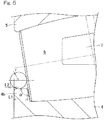
Fig. 5 illustrates a relation between dimensional change of the transport jig and a bearing weight; and -
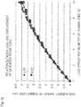
Fig. 6 illustrates a relation between a load and a displacement of the transport jig. - A first embodiment of the present invention will be described with reference to
Fig. 1 and Fig. 2 . Atransport jig 1 is a jig that is to be packed together with a double-row self-aligningroller bearing 2 by apackaging material 3 when the double-row self-aligningroller bearing 2 is transported. The double-row self-aligningroller bearing 2 to be transported is of a type in which a plurality of rollingelements 6 each composed of a barrel-shaped roller are interposed in two rows between aninner ring 4 and anouter ring 5, theouter ring 5 has aspherical raceway 5a continuous over both rows, and anintermediate flange 4a is provided at the center of theinner ring 4.Small flanges elements inner ring 4. The rollingelements retainers retainers roller bearing 2 is, for example, a bearing to be used as a bearing for a main shaft of a wind power generator, and is a large bearing. - Each of the opposite end portions of the double-row self-aligning
roller bearing 2 is attached with onetransport jig 1. Eachtransport jig 1 is formed in a ring shape having an inner diameter and an outer diameter that allow thetransport jig 1 to be radially accommodated between an outer circumferential surface of an end portion of theinner ring 4 and an inner circumferential surface of an end portion of theouter ring 5 of the double-row self-aligningroller bearing 2, and has a shape such that one side surface of thetransport jig 1 comes into contact with end surfaces of the rollingelements 6 of the double-row self-aligningroller bearing 2 and another side surface of thetransport jig 1 protrudes beyond the end surfaces of theinner ring 4 and theouter ring 5. - Each
transport jig 1 is formed from a material that is softer than the rollingelements 6. Specifically, thetransport jig 1 is, for example, an integrally molded article formed from a rubber or a resin material such as various synthetic resins. In this example, a cross-sectional shape of thetransport jig 1 is a non-isosceles trapezoid that has a longer base on the radially inner side extending toward the inner side in the bearing width direction (the center side in the axial direction). The degree of inclination of an oblique side of the trapezoid is equal to the degree of inclination of the end surfaces of the rollingelements 6 in a reference state of thetransport jig 1 to be transported. - A transport method will be described. The two
transport jigs 1 are prepared and are respectively placed on opposite end surfaces of the double-row self-aligningroller bearing 2 in a state where thetransport jigs 1 are in contact with the rollingelements 6 at radial positions corresponding to those of the space between theinner ring 4 and theouter ring 5. The double-row self-aligningroller bearing 2, together with thetransport jigs 1 at opposite sides, is covered with thepackaging material 3 over the inner circumferential surface, the outer circumferential surface, and opposite end surfaces of the double-row self-aligningroller bearing 2. Thepackaging material 3 is, for example, a resin film such as a vinyl film. Thepackaging material 3 may have a wide shape or may have a band shape. Thepackaging material 3 is, for example, wound in a spiral manner. InFig. 1 , lines indicated byreference numeral 3a indicate the edges of respective layer portions of thepackaging material 3 wound on the double-row self-aligningroller bearing 2 and the transport jigs 1. By covering the double-row self-aligningroller bearing 2 and thetransport jigs 1 in this manner, a state where portions of thetransport jigs inner ring 4 and theouter ring 5 are pressed toward the center side in the bearing width direction by thepackaging material 3, is attained. - With the
transport jigs 1 having the above described configuration, the following advantages can be obtained. The self-aligningroller bearing 2 is transported in an assembled state. Since gaps are present between therolling elements 6 and the inner andouter rings elements 6 are movable during transportation of the self-aligningroller bearing 2 as is, and there is a possibility of occurrence of damage such as fretting. On the other hand, in this embodiment, when packing the double-row self-aligningroller bearing 2 by winding the film-like packaging material 3 on the double-row self-aligningroller bearing 2, the ring-shapedtransport jigs 1 are mounted on the end surfaces of the rollingelements 6 and packed together with the double-row self-aligningroller bearing 2, whereby thetransport jigs 1 and the double-row self-aligningroller bearing 2 are fixed. By packing the double-row self-aligningroller bearing 2 in this manner, the rollingelements 6 are pressed against theintermediate flange 4a by thetransport jigs 1 as conceptually shown with arrows inFig. 2 . Thus, it is possible to fix each rollingelement 6 through three-point contact of thetransport jig 1, the rollingelement 6, and theintermediate flange 4a, so that damage can be prevented. - The outward facing end surfaces of the rolling
elements 6 of the double-row self-aligningroller bearing 1 are each a surface inclined such that the bearing radially inner side thereof is located at the center side in the bearing width direction with respect to the bearing radially outer side thereof in a state where the rollingelements 6 are fitted in. Thus, if a transverse cross-sectional shape of eachtransport jig 1 is a trapezoid that has a longer base on the radially inner side, thetransport jig 1 can come into contact with the rollingelements 6 along the inclined end surfaces of the rollingelements 6 to press a wide range of the end surfaces of the rollingelements 6, so that the pressing state can be stabilized. - In the following description, parts corresponding to the matters described in the preceding embodiment are designated by the same reference numerals, and the redundant description thereof is omitted. When only a part of a configuration is described, the remaining part of the configuration is the same as that described in the preceding embodiment, unless otherwise specified. The same advantageous effects are achieved by the same configuration. A combination of parts that are specifically described in respective embodiments may be implemented, and, further, embodiments may be partially combined with each other unless such combination causes any problem.
-
Fig. 3 shows another embodiment of the present invention. In this embodiment, the cross-sectional shape of eachtransport jig 1 in the first embodiment shown inFig. 1 is made into a circular shape or an elliptical shape in a normal state. The material of eachtransport jig 1 is a rubber or a resin that is the same as in the first embodiment. As for the hardness of thetransport jig 1, thetransport jig 1 may be preferably soft enough to conform to the inclination of the end surfaces of the rollingelements 6 in a state where thetransport jig 1 is pressed against the rollingelements 6. - In the case of this embodiment, the
transport jig 1 deforms so as to conform to the inclined end surfaces of the rollingelements 6 and presses the rollingelements 6. Thus, thetransport jig 1 can stably press the rollingelements 6. The other configuration and effects in this embodiment are the same as in the first embodiment. -
Fig. 4 is an enlarged cross-sectional view showing a relation between dimensional change of thetransport jig 1 and the double-row self-aligningroller bearing 2 in an enlarged manner. The transverse cross-sectional shape of thetransport jig 1 in this example is a circular shape in the normal state. - In order to more effectively prevent damage to the double-row self-aligning roller bearing, it is effective to press the rolling
elements 6 with greater force at a load that does not cause damage at portions where the end surfaces of the rollingelements 6 and theintermediate flange 4a are in contact with each other, and a state where thetransport jig 1 protrudes beyond the bearing end surface (the end surfaces of theinner ring 4 and the outer ring 5) needs to be attained even when thetransport jig 1 deforms upon reception of the total bearing weight. The effect of preventing damage to the double-row self-aligning roller bearing can be exhibited more by satisfying the following formula.
- Therefore, the following examination and investigation were conducted.
- A load applied per 1 mm of an annular jig is denoted by x. The load x and an amount of dimensional change y of the jig upon reception of a certain load correlate with each other.

- When it is assumed that the jig is mounted along the radially outer surface of the small flange of the inner ring of a certain double-row self-aligning roller bearing A, a load xA applied per 1 mm of the jig and an amount of dimensional change yA of the jig are as follows.


- In this condition, when the total weight of the double-row self-aligning roller bearing A is received by the jig, the jig dimension in the load direction is as follows.

- Moreover, as shown in
Fig. 5 , the dimensions of the double-row self-aligning roller bearing and the jig to be used are set as follows. - r: a transverse cross-section radius of the jig (mm)
- L1: a width dimension of a small flange of an inner ring (mm)
- L2: a distance in the axial direction between an axial end portion of the jig and the end surface of the inner ring when the jig with the radius r is mounted on the radially outer side of the small flange of the inner ring (mm)
- α: an angle of the small flange of the inner ring (°)
- Under this condition, the following formulas are satisfied.


- Furthermore, by setting the jig dimensions such that L2 - f(x) ≥ 0 is satisfied, a state where the end surface of the jig protrudes beyond the end surface of the bearing is attained even when the jig receives the total weight of the bearing.
- As an example, a rubber round cord made of chloroprene rubber (abbreviated as CR) was used for this jig, and a relation between load and displacement of a ϕ-20 jig in which a cross-section of a CR rubber round cord has a diameter of 20 mm and a ϕ-16 jig in which a cross-section of a CR rubber round cord has a diameter of 16 mm was measured. The results are shown in
Fig. 6 . - Moreover, a certain double-row self-aligning roller bearing A is assumed to have an inner ring small flange outer diameter dimension of 900 mm, an inner ring small flange width dimension of 15 mm, an inner ring
small flange angle 10°, and a bearing load of 1500 kg, and the ϕ-20 jig is used as a jig. - Under this condition, each value is as follows.
x ≈ 5.15, f(x) ≈ 2.5, L2 ≈ 6.9 - Thus, L2 - f(x) ≈ 6.9 - 2.5 = 4.4 ≥ 0 is established, so that a state where the end surface of the jig protrudes beyond the end surface of the bearing is attained even when the jig receives the total weight of the bearing. Accordingly, the rolling elements can be pressed with greater force at a load that does not cause damage at portions where the intermediate flange and the end surfaces of the rolling elements are in contact with each other. Therefore, it is possible to more effectively prevent fretting damage that occurs due to roller vibration during transportation.
- It was examined whether there was a problem in supporting the total weight of the bearing only by the contact surfaces of the intermediate flange and the rollers in one row. When a product is horizontally placed, if a jig is made to protrude beyond the end surface of the bearing even upon reception of the total weight of the bearing, the contact surfaces of the intermediate flange of the inner ring and the roller row that is located at the lower side when the product is horizontally placed support the total weight of the bearing. Surface pressure between the rollers and the intermediate flange in this situation is examined.
- The surface pressure P under the condition described above is as follows.

- The acceptable safety factor of a wind power generator is defined in GL standard such that S0 ≥ 2.0. When an acceptable contact surface pressure is estimated from this acceptable safety factor, the acceptable contact surface pressure is approximately 2800 MPa, and thus the surface pressure P needs to satisfy the following.

- Because of the above two formulas, when the total weight of the bearing is supported only by the contact surfaces of the rollers in one row and the intermediate flange and P = 2800 MPa, an area S needs to satisfy the following.

- When the weight of a large double-row self-aligning roller bearing for a windmill is at most 3000 kg, Smin is as follows.

- When it is assumed that 30 rollers are used in one row of the double-row self-aligning roller bearing, an area S'min of a contact surface with the intermediate flange per one roller is as follows.

- Meanwhile, when the minimum diameter of the end surface of each roller used in the large double-row self-aligning roller bearing for a windmill is 50 mm, the following is satisfied.

- Accordingly, when the contact surface of the roller and the intermediate flange has an area not larger than approximately 0.02% of the area of the entire roller end surface, 2800 MPa, which is the acceptable contact surface pressure, is applied, but this is a very low value, so that it can be determined that there is no problem.
- Although the modes for carrying out the present invention have been described on the basis of the embodiments, the embodiments disclosed herein are illustrative in all aspects and not restrictive. The scope of the present invention is indicated by the claims, rather than by the above description, and is intended to include any modifications within the scope and meaning equivalent to the claims.
-
- 1
- Transport jig
- 2
- Double-row self-aligning roller bearing
- 3
- Packaging material
- 4
- Inner ring
- 4a
- Intermediate flange
- 4b
- Small flange
- 5
- Outer ring
- 6
- Rolling element
- 7
- Retainer
Claims (7)
- A transport jig for a double-row self-aligning roller bearing, the transport jig being to be packed together with the double-row self-aligning roller bearing having an intermediate flange when the double-row self-aligning roller bearing is transported,
wherein the transport jig is formed in a ring shape having an inner diameter and an outer diameter that allow the transport jig to be radially accommodated between an outer circumferential surface of an end portion of an inner ring of the double-row self-aligning roller bearing and an inner circumferential surface of an end portion of an outer ring of the double-row self-aligning roller bearing, and has a shape such that one side surface of the transport jig comes into contact with an end surface of each rolling element of the double-row self-aligning roller bearing and another side surface of the transport jig protrudes beyond end surfaces of the inner ring and the outer ring, and
the transport jig is formed from a material that is softer than the rolling elements. - The transport jig for a double-row self-aligning roller bearing as claimed in claim 1, wherein the material is a rubber.
- The transport jig for a double-row self-aligning roller bearing as claimed in claim 1, wherein the material is a resin.
- The transport jig for a double-row self-aligning roller bearing as claimed in any one of claims 1 to 3, wherein a transverse cross-sectional shape of the transport jig is a trapezoid that has a longer base on a radially inner side.
- The transport jig for a double-row self-aligning roller bearing as claimed in any one of claims 1 to 3, wherein a transverse cross-sectional shape of the transport jig is a circular shape or an elliptical shape in a normal state.
- The transport jig for a double-row self-aligning roller bearing as claimed in any one of claims 1 to 3, wherein
a transverse cross-sectional shape of the transport jig is a circular shape in a normal state, and
the following formula (1), formula (2), formula (3), and formula (4) are satisfied,


- A method for individually packing and transporting a double-row self-aligning roller bearing having a flange, the method comprising:placing the transport jig as claimed in any one of claims 1 to 6 at each of opposite end surfaces of each double-row self-aligning roller bearing such that the transport jig is in contact with the rolling elements;covering the double-row self-aligning roller bearing together with the transport jigs placed at opposite sides with a film-like packaging material over an inner circumferential surface, an outer circumferential surface, and opposite end surfaces of the double-row self-aligning roller bearing; andattaining a state where portions of the transport jigs that protrude beyond the end surfaces of the inner ring and the outer ring are pressed toward a center side in a bearing width direction by the packaging material.
Applications Claiming Priority (3)
| Application Number | Priority Date | Filing Date | Title |
|---|---|---|---|
| JP2017044695 | 2017-03-09 | ||
| JP2018022668A JP7156802B2 (en) | 2017-03-09 | 2018-02-13 | Damage-preventing transportation jig and transportation method for double-row spherical roller bearing |
| PCT/JP2018/008357 WO2018164061A1 (en) | 2017-03-09 | 2018-03-05 | Transport jig for double-row self-aligning roller bearing and transport method |
Publications (3)
| Publication Number | Publication Date |
|---|---|
| EP3594519A1 true EP3594519A1 (en) | 2020-01-15 |
| EP3594519A4 EP3594519A4 (en) | 2020-12-09 |
| EP3594519B1 EP3594519B1 (en) | 2023-11-22 |
Family
ID=63680629
Family Applications (1)
| Application Number | Title | Priority Date | Filing Date |
|---|---|---|---|
| EP18764787.0A Active EP3594519B1 (en) | 2017-03-09 | 2018-03-05 | Transport jig and transport method for double-row self-aligning roller bearing |
Country Status (4)
| Country | Link |
|---|---|
| US (1) | US11111963B2 (en) |
| EP (1) | EP3594519B1 (en) |
| JP (1) | JP7156802B2 (en) |
| CN (1) | CN110352306A (en) |
Families Citing this family (1)
| Publication number | Priority date | Publication date | Assignee | Title |
|---|---|---|---|---|
| DE102018221928A1 (en) * | 2018-12-17 | 2020-06-18 | Aktiebolaget Skf | System with a roller bearing |
Family Cites Families (7)
| Publication number | Priority date | Publication date | Assignee | Title |
|---|---|---|---|---|
| US3080964A (en) * | 1959-05-01 | 1963-03-12 | Buckeye Molding Co | Container |
| JP4977332B2 (en) * | 2004-05-13 | 2012-07-18 | 日本精工株式会社 | Cushioning material |
| JP2006090357A (en) | 2004-09-21 | 2006-04-06 | Nsk Ltd | Separator for preventing damage of rolling bearing, bearing using the same, and packing method |
| JP2007119014A (en) * | 2005-10-28 | 2007-05-17 | Nsk Ltd | Bearing packing method and packed bearing |
| WO2014054149A1 (en) | 2012-10-04 | 2014-04-10 | 株式会社不二越 | Method for packaging double-row self-aligning roller bearing |
| US20160290404A1 (en) | 2013-11-06 | 2016-10-06 | Aktiebolaget Skf | Packaging device for rolling element bearings |
| GB2535779B (en) * | 2015-02-27 | 2018-05-09 | Skf Ab | Generator assembly and bearing equipped with the same |
-
2018
- 2018-02-13 JP JP2018022668A patent/JP7156802B2/en active Active
- 2018-03-05 CN CN201880014779.9A patent/CN110352306A/en active Pending
- 2018-03-05 EP EP18764787.0A patent/EP3594519B1/en active Active
-
2019
- 2019-09-04 US US16/560,165 patent/US11111963B2/en active Active
Also Published As
| Publication number | Publication date |
|---|---|
| EP3594519B1 (en) | 2023-11-22 |
| EP3594519A4 (en) | 2020-12-09 |
| US20190390716A1 (en) | 2019-12-26 |
| US11111963B2 (en) | 2021-09-07 |
| CN110352306A (en) | 2019-10-18 |
| JP7156802B2 (en) | 2022-10-19 |
| JP2018151065A (en) | 2018-09-27 |
Similar Documents
| Publication | Publication Date | Title |
|---|---|---|
| US8770853B2 (en) | Split cage for rolling bearing | |
| US10619668B2 (en) | Tapered roller bearing | |
| US20040076355A1 (en) | Single row deep groove radial ball bearing | |
| US9593718B2 (en) | Multipoint contact ball bearing | |
| US8596876B2 (en) | Bearing assembly | |
| US8950945B2 (en) | Roller bearing for a tunneller | |
| US10161450B2 (en) | Ball bearing | |
| EP2899413A1 (en) | Wind/tidal power generation bearing | |
| US20150098825A1 (en) | Bearing arrangement | |
| US20150098671A1 (en) | Toroidal roller bearing | |
| US8100587B2 (en) | Bearing arrangement | |
| EP3594519B1 (en) | Transport jig and transport method for double-row self-aligning roller bearing | |
| JP6456919B2 (en) | Rolling bearings with rolling elements arranged in several cage segments | |
| US7963702B2 (en) | Roller bearing | |
| US20140064650A1 (en) | Bearing arrangement with a back-up bearing, in particular for mountnig a rapidly rotating shaft | |
| WO2018164061A1 (en) | Transport jig for double-row self-aligning roller bearing and transport method | |
| US11815130B2 (en) | Follower bearing | |
| JP2014234907A (en) | Pulley device | |
| US20250271032A1 (en) | Crown-type retainer for ball bearing, and ball bearing | |
| US20250264132A1 (en) | Crown-type retainer for ball bearing, and ball bearing | |
| US20170204907A1 (en) | Bearing-equipped resin pulley | |
| JP4605099B2 (en) | Deep groove ball bearing | |
| US20210025447A1 (en) | Bearing package | |
| US20240084847A1 (en) | Double-row tapered roller bearing assembling jig, and assembling method for double-row tapered roller bearing | |
| EP1956255A1 (en) | Tapered roller bearing |
Legal Events
| Date | Code | Title | Description |
|---|---|---|---|
| STAA | Information on the status of an ep patent application or granted ep patent |
Free format text: STATUS: THE INTERNATIONAL PUBLICATION HAS BEEN MADE |
|
| PUAI | Public reference made under article 153(3) epc to a published international application that has entered the european phase |
Free format text: ORIGINAL CODE: 0009012 |
|
| STAA | Information on the status of an ep patent application or granted ep patent |
Free format text: STATUS: REQUEST FOR EXAMINATION WAS MADE |
|
| 17P | Request for examination filed |
Effective date: 20190927 |
|
| AK | Designated contracting states |
Kind code of ref document: A1 Designated state(s): AL AT BE BG CH CY CZ DE DK EE ES FI FR GB GR HR HU IE IS IT LI LT LU LV MC MK MT NL NO PL PT RO RS SE SI SK SM TR |
|
| AX | Request for extension of the european patent |
Extension state: BA ME |
|
| DAV | Request for validation of the european patent (deleted) | ||
| DAX | Request for extension of the european patent (deleted) | ||
| A4 | Supplementary search report drawn up and despatched |
Effective date: 20201106 |
|
| RIC1 | Information provided on ipc code assigned before grant |
Ipc: F16C 43/04 20060101ALI20201102BHEP Ipc: F16C 41/04 20060101AFI20201102BHEP Ipc: F16C 23/08 20060101ALI20201102BHEP Ipc: F16C 19/38 20060101ALI20201102BHEP |
|
| STAA | Information on the status of an ep patent application or granted ep patent |
Free format text: STATUS: EXAMINATION IS IN PROGRESS |
|
| 17Q | First examination report despatched |
Effective date: 20210909 |
|
| GRAP | Despatch of communication of intention to grant a patent |
Free format text: ORIGINAL CODE: EPIDOSNIGR1 |
|
| STAA | Information on the status of an ep patent application or granted ep patent |
Free format text: STATUS: GRANT OF PATENT IS INTENDED |
|
| INTG | Intention to grant announced |
Effective date: 20230626 |
|
| GRAS | Grant fee paid |
Free format text: ORIGINAL CODE: EPIDOSNIGR3 |
|
| GRAA | (expected) grant |
Free format text: ORIGINAL CODE: 0009210 |
|
| STAA | Information on the status of an ep patent application or granted ep patent |
Free format text: STATUS: THE PATENT HAS BEEN GRANTED |
|
| AK | Designated contracting states |
Kind code of ref document: B1 Designated state(s): AL AT BE BG CH CY CZ DE DK EE ES FI FR GB GR HR HU IE IS IT LI LT LU LV MC MK MT NL NO PL PT RO RS SE SI SK SM TR |
|
| REG | Reference to a national code |
Ref country code: GB Ref legal event code: FG4D |
|
| REG | Reference to a national code |
Ref country code: CH Ref legal event code: EP |
|
| REG | Reference to a national code |
Ref country code: DE Ref legal event code: R096 Ref document number: 602018061468 Country of ref document: DE |
|
| REG | Reference to a national code |
Ref country code: IE Ref legal event code: FG4D |
|
| REG | Reference to a national code |
Ref country code: LT Ref legal event code: MG9D |
|
| REG | Reference to a national code |
Ref country code: NL Ref legal event code: MP Effective date: 20231122 |
|
| PG25 | Lapsed in a contracting state [announced via postgrant information from national office to epo] |
Ref country code: GR Free format text: LAPSE BECAUSE OF FAILURE TO SUBMIT A TRANSLATION OF THE DESCRIPTION OR TO PAY THE FEE WITHIN THE PRESCRIBED TIME-LIMIT Effective date: 20240223 |
|
| PG25 | Lapsed in a contracting state [announced via postgrant information from national office to epo] |
Ref country code: IS Free format text: LAPSE BECAUSE OF FAILURE TO SUBMIT A TRANSLATION OF THE DESCRIPTION OR TO PAY THE FEE WITHIN THE PRESCRIBED TIME-LIMIT Effective date: 20240322 |
|
| PG25 | Lapsed in a contracting state [announced via postgrant information from national office to epo] |
Ref country code: LT Free format text: LAPSE BECAUSE OF FAILURE TO SUBMIT A TRANSLATION OF THE DESCRIPTION OR TO PAY THE FEE WITHIN THE PRESCRIBED TIME-LIMIT Effective date: 20231122 |
|
| REG | Reference to a national code |
Ref country code: AT Ref legal event code: MK05 Ref document number: 1634104 Country of ref document: AT Kind code of ref document: T Effective date: 20231122 |
|
| PG25 | Lapsed in a contracting state [announced via postgrant information from national office to epo] |
Ref country code: NL Free format text: LAPSE BECAUSE OF FAILURE TO SUBMIT A TRANSLATION OF THE DESCRIPTION OR TO PAY THE FEE WITHIN THE PRESCRIBED TIME-LIMIT Effective date: 20231122 |
|
| PG25 | Lapsed in a contracting state [announced via postgrant information from national office to epo] |
Ref country code: AT Free format text: LAPSE BECAUSE OF FAILURE TO SUBMIT A TRANSLATION OF THE DESCRIPTION OR TO PAY THE FEE WITHIN THE PRESCRIBED TIME-LIMIT Effective date: 20231122 |
|
| PG25 | Lapsed in a contracting state [announced via postgrant information from national office to epo] |
Ref country code: ES Free format text: LAPSE BECAUSE OF FAILURE TO SUBMIT A TRANSLATION OF THE DESCRIPTION OR TO PAY THE FEE WITHIN THE PRESCRIBED TIME-LIMIT Effective date: 20231122 |
|
| PG25 | Lapsed in a contracting state [announced via postgrant information from national office to epo] |
Ref country code: NL Free format text: LAPSE BECAUSE OF FAILURE TO SUBMIT A TRANSLATION OF THE DESCRIPTION OR TO PAY THE FEE WITHIN THE PRESCRIBED TIME-LIMIT Effective date: 20231122 Ref country code: LT Free format text: LAPSE BECAUSE OF FAILURE TO SUBMIT A TRANSLATION OF THE DESCRIPTION OR TO PAY THE FEE WITHIN THE PRESCRIBED TIME-LIMIT Effective date: 20231122 Ref country code: IS Free format text: LAPSE BECAUSE OF FAILURE TO SUBMIT A TRANSLATION OF THE DESCRIPTION OR TO PAY THE FEE WITHIN THE PRESCRIBED TIME-LIMIT Effective date: 20240322 Ref country code: GR Free format text: LAPSE BECAUSE OF FAILURE TO SUBMIT A TRANSLATION OF THE DESCRIPTION OR TO PAY THE FEE WITHIN THE PRESCRIBED TIME-LIMIT Effective date: 20240223 Ref country code: ES Free format text: LAPSE BECAUSE OF FAILURE TO SUBMIT A TRANSLATION OF THE DESCRIPTION OR TO PAY THE FEE WITHIN THE PRESCRIBED TIME-LIMIT Effective date: 20231122 Ref country code: BG Free format text: LAPSE BECAUSE OF FAILURE TO SUBMIT A TRANSLATION OF THE DESCRIPTION OR TO PAY THE FEE WITHIN THE PRESCRIBED TIME-LIMIT Effective date: 20240222 Ref country code: AT Free format text: LAPSE BECAUSE OF FAILURE TO SUBMIT A TRANSLATION OF THE DESCRIPTION OR TO PAY THE FEE WITHIN THE PRESCRIBED TIME-LIMIT Effective date: 20231122 Ref country code: PT Free format text: LAPSE BECAUSE OF FAILURE TO SUBMIT A TRANSLATION OF THE DESCRIPTION OR TO PAY THE FEE WITHIN THE PRESCRIBED TIME-LIMIT Effective date: 20240322 |
|
| PG25 | Lapsed in a contracting state [announced via postgrant information from national office to epo] |
Ref country code: SE Free format text: LAPSE BECAUSE OF FAILURE TO SUBMIT A TRANSLATION OF THE DESCRIPTION OR TO PAY THE FEE WITHIN THE PRESCRIBED TIME-LIMIT Effective date: 20231122 Ref country code: RS Free format text: LAPSE BECAUSE OF FAILURE TO SUBMIT A TRANSLATION OF THE DESCRIPTION OR TO PAY THE FEE WITHIN THE PRESCRIBED TIME-LIMIT Effective date: 20231122 Ref country code: PL Free format text: LAPSE BECAUSE OF FAILURE TO SUBMIT A TRANSLATION OF THE DESCRIPTION OR TO PAY THE FEE WITHIN THE PRESCRIBED TIME-LIMIT Effective date: 20231122 Ref country code: NO Free format text: LAPSE BECAUSE OF FAILURE TO SUBMIT A TRANSLATION OF THE DESCRIPTION OR TO PAY THE FEE WITHIN THE PRESCRIBED TIME-LIMIT Effective date: 20240222 Ref country code: LV Free format text: LAPSE BECAUSE OF FAILURE TO SUBMIT A TRANSLATION OF THE DESCRIPTION OR TO PAY THE FEE WITHIN THE PRESCRIBED TIME-LIMIT Effective date: 20231122 Ref country code: HR Free format text: LAPSE BECAUSE OF FAILURE TO SUBMIT A TRANSLATION OF THE DESCRIPTION OR TO PAY THE FEE WITHIN THE PRESCRIBED TIME-LIMIT Effective date: 20231122 |
|
| PG25 | Lapsed in a contracting state [announced via postgrant information from national office to epo] |
Ref country code: DK Free format text: LAPSE BECAUSE OF FAILURE TO SUBMIT A TRANSLATION OF THE DESCRIPTION OR TO PAY THE FEE WITHIN THE PRESCRIBED TIME-LIMIT Effective date: 20231122 |
|
| PG25 | Lapsed in a contracting state [announced via postgrant information from national office to epo] |
Ref country code: CZ Free format text: LAPSE BECAUSE OF FAILURE TO SUBMIT A TRANSLATION OF THE DESCRIPTION OR TO PAY THE FEE WITHIN THE PRESCRIBED TIME-LIMIT Effective date: 20231122 |
|
| PG25 | Lapsed in a contracting state [announced via postgrant information from national office to epo] |
Ref country code: SK Free format text: LAPSE BECAUSE OF FAILURE TO SUBMIT A TRANSLATION OF THE DESCRIPTION OR TO PAY THE FEE WITHIN THE PRESCRIBED TIME-LIMIT Effective date: 20231122 |
|
| PG25 | Lapsed in a contracting state [announced via postgrant information from national office to epo] |
Ref country code: SM Free format text: LAPSE BECAUSE OF FAILURE TO SUBMIT A TRANSLATION OF THE DESCRIPTION OR TO PAY THE FEE WITHIN THE PRESCRIBED TIME-LIMIT Effective date: 20231122 Ref country code: SK Free format text: LAPSE BECAUSE OF FAILURE TO SUBMIT A TRANSLATION OF THE DESCRIPTION OR TO PAY THE FEE WITHIN THE PRESCRIBED TIME-LIMIT Effective date: 20231122 Ref country code: RO Free format text: LAPSE BECAUSE OF FAILURE TO SUBMIT A TRANSLATION OF THE DESCRIPTION OR TO PAY THE FEE WITHIN THE PRESCRIBED TIME-LIMIT Effective date: 20231122 Ref country code: IT Free format text: LAPSE BECAUSE OF FAILURE TO SUBMIT A TRANSLATION OF THE DESCRIPTION OR TO PAY THE FEE WITHIN THE PRESCRIBED TIME-LIMIT Effective date: 20231122 Ref country code: EE Free format text: LAPSE BECAUSE OF FAILURE TO SUBMIT A TRANSLATION OF THE DESCRIPTION OR TO PAY THE FEE WITHIN THE PRESCRIBED TIME-LIMIT Effective date: 20231122 Ref country code: DK Free format text: LAPSE BECAUSE OF FAILURE TO SUBMIT A TRANSLATION OF THE DESCRIPTION OR TO PAY THE FEE WITHIN THE PRESCRIBED TIME-LIMIT Effective date: 20231122 Ref country code: CZ Free format text: LAPSE BECAUSE OF FAILURE TO SUBMIT A TRANSLATION OF THE DESCRIPTION OR TO PAY THE FEE WITHIN THE PRESCRIBED TIME-LIMIT Effective date: 20231122 |
|
| REG | Reference to a national code |
Ref country code: DE Ref legal event code: R097 Ref document number: 602018061468 Country of ref document: DE |
|
| PLBE | No opposition filed within time limit |
Free format text: ORIGINAL CODE: 0009261 |
|
| STAA | Information on the status of an ep patent application or granted ep patent |
Free format text: STATUS: NO OPPOSITION FILED WITHIN TIME LIMIT |
|
| PG25 | Lapsed in a contracting state [announced via postgrant information from national office to epo] |
Ref country code: SI Free format text: LAPSE BECAUSE OF FAILURE TO SUBMIT A TRANSLATION OF THE DESCRIPTION OR TO PAY THE FEE WITHIN THE PRESCRIBED TIME-LIMIT Effective date: 20231122 |
|
| 26N | No opposition filed |
Effective date: 20240823 |
|
| PG25 | Lapsed in a contracting state [announced via postgrant information from national office to epo] |
Ref country code: SI Free format text: LAPSE BECAUSE OF FAILURE TO SUBMIT A TRANSLATION OF THE DESCRIPTION OR TO PAY THE FEE WITHIN THE PRESCRIBED TIME-LIMIT Effective date: 20231122 |
|
| REG | Reference to a national code |
Ref country code: CH Ref legal event code: PL |
|
| PG25 | Lapsed in a contracting state [announced via postgrant information from national office to epo] |
Ref country code: LU Free format text: LAPSE BECAUSE OF NON-PAYMENT OF DUE FEES Effective date: 20240305 |
|
| PG25 | Lapsed in a contracting state [announced via postgrant information from national office to epo] |
Ref country code: MC Free format text: LAPSE BECAUSE OF FAILURE TO SUBMIT A TRANSLATION OF THE DESCRIPTION OR TO PAY THE FEE WITHIN THE PRESCRIBED TIME-LIMIT Effective date: 20231122 |
|
| GBPC | Gb: european patent ceased through non-payment of renewal fee |
Effective date: 20240305 |
|
| PG25 | Lapsed in a contracting state [announced via postgrant information from national office to epo] |
Ref country code: MC Free format text: LAPSE BECAUSE OF FAILURE TO SUBMIT A TRANSLATION OF THE DESCRIPTION OR TO PAY THE FEE WITHIN THE PRESCRIBED TIME-LIMIT Effective date: 20231122 Ref country code: LU Free format text: LAPSE BECAUSE OF NON-PAYMENT OF DUE FEES Effective date: 20240305 |
|
| REG | Reference to a national code |
Ref country code: BE Ref legal event code: MM Effective date: 20240331 |
|
| PG25 | Lapsed in a contracting state [announced via postgrant information from national office to epo] |
Ref country code: BE Free format text: LAPSE BECAUSE OF NON-PAYMENT OF DUE FEES Effective date: 20240331 |
|
| PG25 | Lapsed in a contracting state [announced via postgrant information from national office to epo] |
Ref country code: GB Free format text: LAPSE BECAUSE OF NON-PAYMENT OF DUE FEES Effective date: 20240305 |
|
| PG25 | Lapsed in a contracting state [announced via postgrant information from national office to epo] |
Ref country code: IE Free format text: LAPSE BECAUSE OF NON-PAYMENT OF DUE FEES Effective date: 20240305 |
|
| PG25 | Lapsed in a contracting state [announced via postgrant information from national office to epo] |
Ref country code: IE Free format text: LAPSE BECAUSE OF NON-PAYMENT OF DUE FEES Effective date: 20240305 Ref country code: GB Free format text: LAPSE BECAUSE OF NON-PAYMENT OF DUE FEES Effective date: 20240305 Ref country code: BE Free format text: LAPSE BECAUSE OF NON-PAYMENT OF DUE FEES Effective date: 20240331 Ref country code: CH Free format text: LAPSE BECAUSE OF NON-PAYMENT OF DUE FEES Effective date: 20240331 |
|
| PG25 | Lapsed in a contracting state [announced via postgrant information from national office to epo] |
Ref country code: CY Free format text: LAPSE BECAUSE OF FAILURE TO SUBMIT A TRANSLATION OF THE DESCRIPTION OR TO PAY THE FEE WITHIN THE PRESCRIBED TIME-LIMIT; INVALID AB INITIO Effective date: 20180305 |
|
| PG25 | Lapsed in a contracting state [announced via postgrant information from national office to epo] |
Ref country code: HU Free format text: LAPSE BECAUSE OF FAILURE TO SUBMIT A TRANSLATION OF THE DESCRIPTION OR TO PAY THE FEE WITHIN THE PRESCRIBED TIME-LIMIT; INVALID AB INITIO Effective date: 20180305 |
|
| PG25 | Lapsed in a contracting state [announced via postgrant information from national office to epo] |
Ref country code: FI Free format text: LAPSE BECAUSE OF FAILURE TO SUBMIT A TRANSLATION OF THE DESCRIPTION OR TO PAY THE FEE WITHIN THE PRESCRIBED TIME-LIMIT Effective date: 20231122 |
|
| PG25 | Lapsed in a contracting state [announced via postgrant information from national office to epo] |
Ref country code: TR Free format text: LAPSE BECAUSE OF FAILURE TO SUBMIT A TRANSLATION OF THE DESCRIPTION OR TO PAY THE FEE WITHIN THE PRESCRIBED TIME-LIMIT Effective date: 20231122 |
|
| PGFP | Annual fee paid to national office [announced via postgrant information from national office to epo] |
Ref country code: DE Payment date: 20260128 Year of fee payment: 9 |
|
| PGFP | Annual fee paid to national office [announced via postgrant information from national office to epo] |
Ref country code: FR Payment date: 20260209 Year of fee payment: 9 |