EP3594469B1 - Uniflow scavenging type two-cycle engine - Google Patents
Uniflow scavenging type two-cycle engine Download PDFInfo
- Publication number
- EP3594469B1 EP3594469B1 EP17899392.9A EP17899392A EP3594469B1 EP 3594469 B1 EP3594469 B1 EP 3594469B1 EP 17899392 A EP17899392 A EP 17899392A EP 3594469 B1 EP3594469 B1 EP 3594469B1
- Authority
- EP
- European Patent Office
- Prior art keywords
- cylinder
- scavenging
- piston
- fuel
- dead center
- Prior art date
- Legal status (The legal status is an assumption and is not a legal conclusion. Google has not performed a legal analysis and makes no representation as to the accuracy of the status listed.)
- Active
Links
Images


Classifications
-
- F—MECHANICAL ENGINEERING; LIGHTING; HEATING; WEAPONS; BLASTING
- F02—COMBUSTION ENGINES; HOT-GAS OR COMBUSTION-PRODUCT ENGINE PLANTS
- F02B—INTERNAL-COMBUSTION PISTON ENGINES; COMBUSTION ENGINES IN GENERAL
- F02B25/00—Engines characterised by using fresh charge for scavenging cylinders
- F02B25/02—Engines characterised by using fresh charge for scavenging cylinders using unidirectional scavenging
- F02B25/04—Engines having ports both in cylinder head and in cylinder wall near bottom of piston stroke
-
- F—MECHANICAL ENGINEERING; LIGHTING; HEATING; WEAPONS; BLASTING
- F02—COMBUSTION ENGINES; HOT-GAS OR COMBUSTION-PRODUCT ENGINE PLANTS
- F02B—INTERNAL-COMBUSTION PISTON ENGINES; COMBUSTION ENGINES IN GENERAL
- F02B75/00—Other engines
- F02B75/02—Engines characterised by their cycles, e.g. six-stroke
-
- F—MECHANICAL ENGINEERING; LIGHTING; HEATING; WEAPONS; BLASTING
- F02—COMBUSTION ENGINES; HOT-GAS OR COMBUSTION-PRODUCT ENGINE PLANTS
- F02D—CONTROLLING COMBUSTION ENGINES
- F02D13/00—Controlling the engine output power by varying inlet or exhaust valve operating characteristics, e.g. timing
- F02D13/02—Controlling the engine output power by varying inlet or exhaust valve operating characteristics, e.g. timing during engine operation
- F02D13/0276—Actuation of an additional valve for a special application, e.g. for decompression, exhaust gas recirculation or cylinder scavenging
-
- F—MECHANICAL ENGINEERING; LIGHTING; HEATING; WEAPONS; BLASTING
- F02—COMBUSTION ENGINES; HOT-GAS OR COMBUSTION-PRODUCT ENGINE PLANTS
- F02D—CONTROLLING COMBUSTION ENGINES
- F02D13/00—Controlling the engine output power by varying inlet or exhaust valve operating characteristics, e.g. timing
- F02D13/02—Controlling the engine output power by varying inlet or exhaust valve operating characteristics, e.g. timing during engine operation
- F02D13/028—Controlling the engine output power by varying inlet or exhaust valve operating characteristics, e.g. timing during engine operation for two-stroke engines
-
- F—MECHANICAL ENGINEERING; LIGHTING; HEATING; WEAPONS; BLASTING
- F02—COMBUSTION ENGINES; HOT-GAS OR COMBUSTION-PRODUCT ENGINE PLANTS
- F02D—CONTROLLING COMBUSTION ENGINES
- F02D19/00—Controlling engines characterised by their use of non-liquid fuels, pluralities of fuels, or non-fuel substances added to the combustible mixtures
- F02D19/06—Controlling engines characterised by their use of non-liquid fuels, pluralities of fuels, or non-fuel substances added to the combustible mixtures peculiar to engines working with pluralities of fuels, e.g. alternatively with light and heavy fuel oil, other than engines indifferent to the fuel consumed
- F02D19/0602—Control of components of the fuel supply system
- F02D19/0613—Switch-over from one fuel to another
-
- F—MECHANICAL ENGINEERING; LIGHTING; HEATING; WEAPONS; BLASTING
- F02—COMBUSTION ENGINES; HOT-GAS OR COMBUSTION-PRODUCT ENGINE PLANTS
- F02F—CYLINDERS, PISTONS OR CASINGS, FOR COMBUSTION ENGINES; ARRANGEMENTS OF SEALINGS IN COMBUSTION ENGINES
- F02F1/00—Cylinders; Cylinder heads
- F02F1/18—Other cylinders
- F02F1/22—Other cylinders characterised by having ports in cylinder wall for scavenging or charging
-
- F—MECHANICAL ENGINEERING; LIGHTING; HEATING; WEAPONS; BLASTING
- F02—COMBUSTION ENGINES; HOT-GAS OR COMBUSTION-PRODUCT ENGINE PLANTS
- F02B—INTERNAL-COMBUSTION PISTON ENGINES; COMBUSTION ENGINES IN GENERAL
- F02B75/00—Other engines
- F02B75/02—Engines characterised by their cycles, e.g. six-stroke
- F02B2075/022—Engines characterised by their cycles, e.g. six-stroke having less than six strokes per cycle
- F02B2075/025—Engines characterised by their cycles, e.g. six-stroke having less than six strokes per cycle two
-
- F—MECHANICAL ENGINEERING; LIGHTING; HEATING; WEAPONS; BLASTING
- F02—COMBUSTION ENGINES; HOT-GAS OR COMBUSTION-PRODUCT ENGINE PLANTS
- F02D—CONTROLLING COMBUSTION ENGINES
- F02D13/00—Controlling the engine output power by varying inlet or exhaust valve operating characteristics, e.g. timing
- F02D13/02—Controlling the engine output power by varying inlet or exhaust valve operating characteristics, e.g. timing during engine operation
- F02D13/028—Controlling the engine output power by varying inlet or exhaust valve operating characteristics, e.g. timing during engine operation for two-stroke engines
- F02D13/0284—Variable control of exhaust valves only
-
- Y—GENERAL TAGGING OF NEW TECHNOLOGICAL DEVELOPMENTS; GENERAL TAGGING OF CROSS-SECTIONAL TECHNOLOGIES SPANNING OVER SEVERAL SECTIONS OF THE IPC; TECHNICAL SUBJECTS COVERED BY FORMER USPC CROSS-REFERENCE ART COLLECTIONS [XRACs] AND DIGESTS
- Y02—TECHNOLOGIES OR APPLICATIONS FOR MITIGATION OR ADAPTATION AGAINST CLIMATE CHANGE
- Y02T—CLIMATE CHANGE MITIGATION TECHNOLOGIES RELATED TO TRANSPORTATION
- Y02T10/00—Road transport of goods or passengers
- Y02T10/10—Internal combustion engine [ICE] based vehicles
- Y02T10/12—Improving ICE efficiencies
Definitions
- the upper grooves 152a and the plurality of lower protrusions 154b are each provided at intervals in the circumferential direction.
- the upper grooves 152a and the lower protrusions 154b are not essential structures.
- the circumferential rotation of the lower cylinder 154 with respect to the upper cylinder 152 can be restricted by a simple configuration.
Landscapes
- Engineering & Computer Science (AREA)
- Chemical & Material Sciences (AREA)
- Combustion & Propulsion (AREA)
- Mechanical Engineering (AREA)
- General Engineering & Computer Science (AREA)
- Oil, Petroleum & Natural Gas (AREA)
- Output Control And Ontrol Of Special Type Engine (AREA)
- Cylinder Crankcases Of Internal Combustion Engines (AREA)
- Combustion Methods Of Internal-Combustion Engines (AREA)
Description
- The present disclosure relates to a uniflow scavenging type two-cycle engine.
- In a uniflow scavenging type two-cycle engine which is also used as an engine of a ship, a scavenging port is provided on one end side of a cylinder in the stroke direction of a piston, and an exhaust port is provided on a cylinder cover disposed on the other end side thereof. When fuel is burned in a combustion chamber and the piston pushed by combustion gas generated by the combustion moves to a position closer to the bottom dead center than the scavenging port, active gas is sucked into the inside of the cylinder from the opened scavenging port, and the exhaust gas after the fuel combustion is pushed out of the exhaust port by the active gas and is discharged.
- Further,
JP 2015 151963 A -
DE 197 00 412 A1 discloses a two-stroke engine. The two stroke engine has each piston engaging a slider sleeve with its lower edge of the piston skirt, in the downward stroke. The slider is depressed to open inlet slots for the inlet fuel-air mixture. The slider is connected to three push rods in the cylinder wall with each push rod connected to an exhaust valve in the cylinder head. The exhaust valves are spring loaded into the closed position. The inlet and exhaust are pushed open near the BDC of the piston movement. The valve springs include secondary springs which are engaged when the valves are pushed into the open setting, and thereby reinforce the normal valve springs. The top edge of the slider sleeve has a conical seal and a serrated lip which engages a similar profile on the bottom edge of the piston skirt, to prevent the piston from rotating. -
EP 147 12 28 A2 discloses an internal combustion engine with a scavenging control valve apparatus. A valve operating device drives a scavenging control valve according to an engine's crank angle. The valve operating device controls the scavenging control valve to synchronize the closing timing of a scavenging passage after a bottom dead position with the closing timing of an exhaust valve. -
US 3 815 566 A discloses a low-pollution engine of the type that burns air and fuel to move a piston, wherein a separate combustion chamber is provided near one end of the cylinder and connected to the cylinder by a constricted passageway, the combustion chamber holding enough air to completely burn all of the fuel therein so that substantially only combustion products enter the cylinder. The walls of the combustion chamber are insulated so that they remain heated, and a perforated plate connects the combustion chamber to the cylinder so that the hot combustion products pass through the plate into the cylinder to heat extra air therein and move the piston. The combustion chamber and cylinder are both purged but by different amounts of air, and fuel is admitted to the combustion chamber by an injection nozzle whose fuel stream hits a target in the combustion chamber to further break up and disperse the fuel. -
EP 085 11 01 A1 discloses a diesel engine. The engine comprises a piston which works in a cylinder-liner. At the bottom end of the liner is a slide working with it to form a valve. This moves with the piston away from the liner so as to form with the latter an annular inlet port for scavenging air to the cylinder. The port shuts again with upward movement of the piston towards the top dead-centre position. The slide can be driven to and fro by the piston, while a first spring and-or damper unit is mounted between piston and slide. Further spring and-or damper units aid, restrict and-or damp movement of the slide. -
US 9 194 344 B1 - In liquid fuel and fuel gas, in some cases, the optimum timing for causing the active gas to flow into the cylinder from the scavenging port may differ. Therefore, if the position of the scavenging port is designed in accordance with one of liquid fuel and fuel gas, in some cases, it is difficult to cause the active gas to flow into the cylinder at an appropriate timing when the other fuel is used.
- Moreover, regardless of the presence or absence of fuel switching, the opening and closing timing of the scavenging port affects the efficiency of the engine. For example, if the scavenging port is close to the top dead center of the piston and the opening timing becomes earlier, there is a possibility that the expansion stroke will be shortened, thereby causing a decline in efficiency, and if the scavenging port is close to the bottom dead center of the piston and the closing timing becomes earlier, there is a possibility that the scavenging period of time will be shortened and a sufficient amount of active gas cannot be sucked.
- Therefore, there is a demand for development of a technique for opening and closing the scavenging port at an appropriate timing depending on the operating conditions.
- An object of the present disclosure is to provide a uniflow scavenging type two-cycle engine capable of opening and closing the scavenging port at an appropriate timing depending on the operating conditions.
- This object is achieved by a uniflow scavenging type two-cycle engine having the features of claim 1. Advantageous further developments are defined in the dependent claims.
- According to the present disclosure, it is possible to open and close the scavenging port at an appropriate timing depending on the operating conditions.
-
-
FIG. 1 is an explanatory view showing an entire configuration of a uniflow scavenging type two-cycle engine. -
FIG. 2 is an explanatory view showing the structure of a mover. -
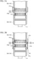
FIG. 3A is a cross-sectional view taken along aline 3A-3A ofFIG. 2 . -
FIG. 3B is a cross-sectional view taken along aline 3B-3B ofFIG. 2 . -
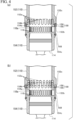
FIG. 4 is an explanatory view showing an operation of the mover. -
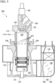
FIG. 5 is an explanatory view showing an entire configuration of a uniflow scavenging type two-cycle engine of a modified example. - Hereinafter, preferred embodiments of the present disclosure will be described in detail with reference to the attached drawings. Dimensions, materials, specific numerical values and the like of constituent elements shown in the present embodiment are merely examples for facilitating understanding of the invention, and do not limit the present disclosure unless otherwise specified. Further, in the specification and the drawings, by denoting elements having substantially the same functions and configurations by the same reference signs, repeated descriptions will be omitted, and elements not directly related to the present disclosure will not be shown.
-
FIG. 1 is an explanatory view showing an entire configuration of a uniflow scavenging type two-cycle engine 100. The uniflow scavenging type two-cycle engine 100 is, for example, used in a ship or the like, and can selectively execute either one operation mode of a gas operation mode for mainly burning fuel gas that is gaseous fuel and a diesel operation mode for burning fuel oil that is liquid fuel. That is, the uniflow scavenging type two-cycle engine 100 is a dual-fuel type engine that switches the fuel between liquid fuel and fuel gas. - Specifically, the uniflow scavenging type two-cycle engine 100 is configured to include a
cylinder 110, acylinder cover 112, apiston 114, apiston rod 116, ascavenging port 118, ascavenging reservoir 120, ascavenging chamber 122, acooler 124, a flow-adjustingplate 126, adrain separator 128, acombustion chamber 130, anexhaust port 132, anexhaust valve 134, an exhaustvalve drive device 136, a liquidfuel injection valve 138, a fuel gasmain pipe 140, afuel injection device 142, anannular pipe 144, afuel pipe 146, afuel injection port 148, and amover 150. Hereinafter, in a central axis direction of the cylinder 110 (an up-down direction in the drawing ofFIG. 1 ), the cylinder cover 112-side may be referred to as an upper side, and the scavenging chamber 122-side may be referred to as a lower side. - In the uniflow scavenging type two-cycle engine 100, the
piston 114 slides inside the cylinder 110 (acylinder liner 110a), and exhausting, intake, compression, combustion, and expansion are performed during two strokes of an up-stroke and a down-stroke of thepiston 114. One end of thepiston rod 116 is fixed to thepiston 114. Further, a cross head (not shown) is connected to the other end of thepiston rod 116, and reciprocates with thepiston 114. When the cross head reciprocates with the reciprocation of thepiston 114, a crankshaft (not shown) rotates in conjunction with the reciprocation. Hereinafter, a direction in which thepiston 114 reciprocates in the central axis direction of thecylinder 110 may be referred to as a stroke direction of thepiston 114. - The
scavenging ports 118 are holes penetrating from an inner peripheral surface to an outer peripheral surface of thecylinder 110, and the plurality ofscavenging ports 118 are provided at intervals on the entire circumference of thecylinder 110. Further, the scavengingports 118 open in a process of movement of thepiston 114 toward the bottom dead center, and cause active gas to flow into thecylinder 110. The active gas contains oxygen, an oxidant such as ozone, or a mixture air thereof (for example, air). Although the scavengingport 118 of the present embodiment is formed in an oval shape extending in the stroke direction when viewed in the radial direction of thecylinder 110, not being limited to such a shape, the scavengingport 118 may have, for example, a circular shape, an elliptical shape, a rectangular shape, a polygonal shape or the like. Hereinafter, the bottom dead center of thepiston 114 may be referred to simply as a bottom dead center, and the top dead center of thepiston 114 may be referred to simply as a top dead center. - Active gas (for example, air) compressed by a supercharger, a blower or the like (not shown) is cooled by the cooler 124 and is sealed in the scavenging
reservoir 120. The active gas flows in the scavengingreservoir 120 from the cooler 124 to the scavengingchamber 122. The compressed and cooled active gas is flow direction-adjusted by the flow-adjustingplates 126 disposed in the scavengingreservoir 120, and then water is removed therefrom by thedrain separator 128. - The scavenging
chamber 122 communicates with the scavengingreservoir 120 and surrounds one end side (a lower side inFIG. 1 ) of thecylinder 110 in the stroke direction of the piston 114 (hereinafter simply referred to as the stroke direction). The active gas subjected to compression, cooling, and removal of water is guided to the scavengingchamber 122 from the scavengingreservoir 120. - The scavenging
ports 118 open in the scavengingchamber 122. When thepiston 114 descends below the scavengingports 118, the inside of thecylinder 110 and the scavengingchamber 122 communicate with each other through the scavengingports 118, and the scavengingports 118 suck the active gas into thecylinder 110 from the scavengingchamber 122 due to a pressure difference between the scavengingchamber 122 and the inside of thecylinder 110. - When the
piston 114 is close to the top dead center, thecombustion chamber 130 is surrounded by the cylinder cover 112 (a cylinder head) disposed to cover an upper end opening portion of thecylinder 110, thecylinder liner 110a, and thepiston 114 and thus is formed inside thecylinder 110. The active gas and the fuel gas sucked into thecylinder 110 are guided to thecombustion chamber 130 by thepiston 114. - The
exhaust port 132 is formed on the upper side of thecombustion chamber 130 inFIG. 1 and is opened and closed to discharge the exhaust gas generated by burning the fuel gas in thecylinder 110 outward of thecylinder 110. Theexhaust valve 134 is slid up and down by the exhaustvalve drive device 136 at predetermined timings to open and close theexhaust port 132. After combustion of the fuel gas, when theexhaust valve 134 is opened, the exhaust gas in thecylinder 110 is pushed out of theexhaust port 132 by the active gas (scavenging air) flowing in from the scavengingports 118. - Further, as described above, a diesel operation mode and a gas operation mode are provided in the uniflow scavenging type two-cycle engine 100 of the present embodiment. A liquid fuel supply mechanism to be mainly used in the diesel operation mode and a fuel gas supply mechanism to be mainly used in the gas operation mode will be described below.
- The liquid
fuel injection valve 138 is provided on thecylinder cover 112, and a tip thereof protrudes into thecombustion chamber 130, and the liquidfuel injection valve 138 injects the fuel oil from the tip into thecombustion chamber 130 in the diesel operation mode. - The fuel gas
main pipe 140 communicates with a fuel tank (not shown) and communicates with theannular pipe 144 via thefuel injection device 142. The fuel gas is guided from the fuel tank to the fuel gasmain pipe 140, and when thefuel injection device 142 is operated, the fuel gas in the fuel gasmain pipe 140 flows into theannular pipe 144. - Here, the fuel gas is, for example, a gas generated by gasifying LNG (Liquefied Natural Gas). Further, the fuel gas is not limited to LNG, and it is possible to use a gas obtained by gasifying, for example, LPG (Liquefied Petroleum Gas), light oil, heavy oil or the like.
- The
annular pipe 144 is disposed radially outward of thecylinder 110 and above the scavengingports 118 inFIG. 1 and extends annularly in the circumferential direction of thecylinder 110 to surround thecylinder 110. A plurality offuel pipes 146 are fixed to the scavenging port 118-side of theannular pipe 144 in the stroke direction (that is, the lower side inFIG. 1 ). Onefuel pipe 146 is disposed for each scavengingport 118 and extends in the stroke direction. Hereinafter, the radial direction of thecylinder 110 may be referred to simply as a radial direction, and the circumferential direction of thecylinder 110 may be referred to simply as a circumferential direction. - The
fuel pipe 146 faces a wall surface of thecylinder 110 between scavengingports 118 adjacent to each other in the circumferential direction, and thefuel injection port 148 is formed on a portion of thefuel pipe 146 facing the wall surface. Here, since a plurality of scavengingports 118 are provided on the entire circumference of thecylinder 110, a plurality of fuel pipes 146 (the fuel injection ports 148) are also provided in the circumferential direction of thecylinder 110 in accordance with the scavengingports 118. - The
fuel injection ports 148 inject the fuel gas flowed into theannular pipe 144 into the active gas to be sucked into the scavengingports 118. As a result, the fuel gas joins the flow of the active gas and is sucked into thecylinder 110 from the scavengingports 118 together with the active gas. - At a desired time point in the engine cycle, a suitable amount of the fuel oil (an amount smaller than in the diesel operation mode) is injected from the liquid
fuel injection valve 138. The fuel oil is vaporized by heat of thecombustion chamber 130. Further, the fuel oil is vaporized and spontaneously ignited and burns in a short time, the temperature of thecombustion chamber 130 becomes extremely high, and the fuel gas guided to thecombustion chamber 130 and compressed is burned. Thepiston 114 is reciprocated mainly by the expansion pressure due to the combustion of the fuel gas. - In the fuel gas and the fuel oil, that is, in the gas operation mode and the diesel operation mode, in some cases, the optimum timings for causing the active gas to flow into the
cylinder 110 from the scavengingport 118 may be different. Therefore, if the position of the scavengingport 118 is designed in accordance with either one of the fuel gas and the fuel oil, in some cases, it may be difficult to cause the active gas to flow into thecylinder 110 at an appropriate timing when the other fuel is used. - Therefore, the uniflow scavenging type two-cycle engine 100 is provided with the
mover 150 that changes the position of the scavengingport 118 in the stroke direction. -
FIGS. 2 ,3A, and 3B are explanatory views showing the structure of themover 150.FIG. 2 extracts and shows the vicinity of the scavengingports 118 inFIG. 1 ,FIG. 3A shows a cross section taken along aline 3A-3A ofFIG. 2 , andFIG. 3B shows a cross section taken along aline 3B-3B ofFIG. 2 . Here,FIGS. 3A and 3B show cross-sectional views each including the central axis of thecylinder 110. - As shown in
FIG. 2 , the cylinder 110 (thecylinder liner 110a) is configured to include anupper cylinder 152 on an upper side (the cylinder cover 112-side ofFIG. 1 ) inFIG. 2 , and alower cylinder 154 disposed below (thepiston 114's bottom dead center-side of) theupper cylinder 152 inFIG. 2 . Theupper cylinder 152 is positioned to be closer to thepiston 114's top dead center than thelower cylinder 154, and the scavengingports 118 are formed in thelower cylinder 154. - On an inner peripheral surface of the lower end portion on the lower side (the lower cylinder 154-side) of the
upper cylinder 152 inFIG. 2 , anupper groove 152a recessed radially outward from the inner peripheral surface is provided. As shown inFIGS. 3A and 3B , a plurality ofupper grooves 152a are provided at intervals in the circumferential direction, and extend in the stroke direction. Theupper grooves 152a open downward of theupper cylinder 152. - Further, on the
upper end surface 154a on the upper side (the upper cylinder 152-side) of thelower cylinder 154 inFIG. 2 , alower protrusion 154b protruding toward theupper cylinder 152 is provided. Thelower protrusion 154b is provided in a portion on the radially inner side of theupper end surface 154a. As shown inFIGS. 3A and 3B , a plurality oflower protrusions 154b are provided to be spaced apart from each other in the circumferential direction at the same intervals as theupper grooves 152a, and the length (height) in the stroke direction of thelower protrusion 154b is substantially equal to the length in the stroke direction of theupper groove 152a. - Further, the
upper end surface 154a (end portion) of thelower cylinder 154 is inserted through (into) theupper cylinder 152 in the stroke direction, and the plurality oflower protrusions 154b of thelower cylinder 154 are inserted into the plurality ofupper grooves 152a of theupper cylinder 152 in the stroke direction. That is, the upper end portion of thelower cylinder 154 other than thelower protrusions 154b is closely inserted into the lower end portion of theupper cylinder 152 below theupper grooves 152a to be slidable in the stroke direction. By fitting thelower protrusion 154b into theupper groove 152a, circumferential rotation of thelower cylinder 154 with respect to theupper cylinder 152 is restricted. In addition, thelower protrusion 154b can slide in theupper groove 152a in the stroke direction, and thelower cylinder 154 can relatively move with respect to theupper cylinder 152 in the stroke direction. - Further, the inner diameter of the upper cylinder 152 (the inner diameter of the portion of the
upper cylinder 152 above theupper grooves 152a) and the inner diameter of thelower cylinder 154 are substantially equal to each other, and portions in which thelower protrusions 154b are inserted into theupper grooves 152a are designed such that there are almost no steps in the circumferential direction. - The
mover 150 is provided in a connection portion between theupper cylinder 152 and thelower cylinder 154, and moves thelower cylinder 154 in the stroke direction with respect to theupper cylinder 152. Specifically, themover 150 is configured of a hydraulic mechanism, and includes ahydraulic piston 156 and ahydraulic chamber 158. However, themover 150 is not limited to a hydraulic mechanism, and may have any configuration as long as thelower cylinder 154 can be moved in the stroke direction with respect to theupper cylinder 152. - A
hollow portion 152c is provided in a portion of the lower end portion of theupper cylinder 152, which is radially outward of theupper grooves 152a. A plurality (for example, four in this case) ofhollow portions 152c are disposed to be spaced apart from each other in the circumferential direction of theupper cylinder 152, and symmetrically with respect to the central axis of theupper cylinder 152. That is, thehollow portions 152c are disposed at equal intervals in the circumferential direction of theupper cylinder 152. Thehydraulic piston 156 is disposed inside thehollow portion 152c to be slidable in the stroke direction, and divides thehollow portion 152c into two spaces in the stroke direction. - The
hydraulic chamber 158 is a space on the lower side (the lower cylinder 154-side) of thehollow portion 152c inFIG. 2 , which is partitioned by thehydraulic piston 156. Thehydraulic chamber 158 communicates with an oil pump (not shown), and pressure-increased hydraulic oil is supplied from the oil pump to thehydraulic chamber 158. - When the hydraulic oil is supplied to the
hydraulic chamber 158, thehydraulic piston 156 is moved upward inFIG. 2 by the hydraulic pressure of the hydraulic oil supplied to thehydraulic chamber 158. Further, when the hydraulic oil is discharged from thehydraulic chamber 158, thehydraulic piston 156 moves downward inFIG. 2 by gravity. Further, for example, a configuration in which the pressure-increased hydraulic oil is alternately supplied to the two spaces divided by thehydraulic piston 156 in thehollow portion 152c and thehydraulic piston 156 reciprocates in the stroke direction may be provided. The movement of thehydraulic piston 156 to either one side in the stroke direction may be performed by the hydraulic oil, and the movement to the other side may be performed by another external force (gravity or a pushing force of a spring or the like). - A
shaft 160 is fixed to the lower side of thehydraulic piston 156 inFIG. 2 . Theshaft 160 penetrates a wall portion of theupper cylinder 152 below thehydraulic chamber 158 inFIG. 2 and extends to a position below the scavengingport 118 in the stroke direction. The lower end portion of theshaft 160 is fixed to aprotrusion 154c provided on the outer peripheral surface of thelower cylinder 154. -
FIG. 4 is an explanatory view showing the operation of themover 150. The part (a) ofFIG. 4 shown on the upper side of the drawing ofFIG. 4 shows a state in which thelower cylinder 154 is at the uppermost position (a position at which thelower cylinder 154 is closest to the top dead center of thepiston 114, and a position at which thelower cylinder 154 is closest to the upper cylinder 152). The part (b) ofFIG. 4 shown on the lower side of the drawing ofFIG. 4 shows a state in which thelower cylinder 154 is at the lowermost position (a position at which thelower cylinder 154 is farthest away from the top dead center of thepiston 114 in the stroke direction, and a position at which thelower cylinder 154 is farthest away from theupper cylinder 152 in the stroke direction). As shown in the parts (a) and (b) ofFIG. 4 , when thehydraulic piston 156 moves upward inFIG. 4 by hydraulic pressure or the like, thelower cylinder 154 connected to thehydraulic piston 156 via theshaft 160 also moves upward. Similarly, when thehydraulic piston 156 moves downward inFIG. 4 by hydraulic pressure or the like, thelower cylinder 154 also moves downward. - In this way, a configuration in which the position of the
lower cylinder 154 with respect to theupper cylinder 152 is displaced in the stroke direction by themover 150 is provided. As a result, the position of the scavengingport 118 provided in thelower cylinder 154 is also displaced in the stroke direction. That is, theopening position 118a on thepiston 114's top dead center-side of the scavengingport 118 is displaced in the stroke direction. In other words, the position of the opening edge on thepiston 114's top dead center-side of the scavenging port 118 (the position of the opening edge closest to the top dead center of thepiston 114, the position of the opening edge closest to the upper cylinder 152) can be changed in the stroke direction by themover 150. - As described above, in the fuel gas and the fuel oil, in some cases, the optimum timings for causing the active gas to flow into the
cylinder 110 from the scavengingport 118 may differ. Specifically, in the case of using the fuel oil, in some cases, it may be preferable that the scavengingport 118 be disposed at a position away from the top dead center (the lower side inFIG. 4 ) to secure a long expansion stroke after the fuel combustion. On the other hand, in the case of using the fuel gas, in some cases, in order to discharge a large amount of high-temperature exhaust gas in thecombustion chamber 130 which causes preignition, it may be preferable that the scavengingport 118 be disposed to be close to the top dead center (the upper side inFIG. 4 ) to start the scavenging by the active gas early. - In the diesel operation mode using the fuel oil, as shown in the part (b) of
FIG. 4 , by moving thelower cylinder 154 downward, and in the gas operation mode using the fuel gas, as shown in the part (a) ofFIG. 4 , by moving thelower cylinder 154 upward, it is possible to cause the active gas to flow into thecylinder 110 from the scavengingport 118 at an appropriate timing. As a result, in the diesel operation mode, a long expansion stroke can be secured to improve the efficiency, and in the gas operation mode, it is possible to increase the injection amount of the fuel gas and to raise the output because the occurrence of preignition is limited. - Further, as shown in the part (a) of
FIG. 4 , in a state in which thelower cylinder 154 is displaced to the closemost positon to the top dead center, theopening position 118a on the top dead center-side of the scavengingport 118 is to be closer to the bottom dead center than thelower end surface 152b of the upper cylinder 152 (the end portion on the bottom dead center-side). - Therefore, it is possible to avoid a situation in which the
upper cylinder 152 covers part of the scavengingport 118 and the inflow of the active gas from the scavengingport 118 is disturbed by theupper cylinder 152, and it is possible to perform inflow of the active gas at an appropriate timing. -
FIG. 5 is an explanatory view showing an entire configuration of a uniflow scavenging type two-cycle engine 200 of a modified example of the above embodiment. In the embodiment described above, the case in which thefuel injection port 148 of the fuel gas supply mechanism injects the fuel gas into the active gas to be sucked into the scavengingport 118 has been described. In the present modified example, afuel injection port 202 of the fuel gas supply mechanism is provided in a portion of thecylinder 110 between the scavengingport 118 and theexhaust port 132. - A plurality of
fuel injection ports 202 are provided at intervals in the circumferential direction of thecylinder 110. Afuel injection valve 204 is disposed at eachfuel injection port 202. Thefuel injection valve 204 communicates with afuel pipe 206 and injects the fuel gas guided from thefuel pipe 206 into thecylinder 110 through thefuel injection port 202. - In this way, the fuel gas supply mechanism is not limited to the configuration in which the
fuel injection port 148 injects the fuel gas into the active gas to be sucked into the scavengingport 118, and may have a configuration in which thefuel injection port 202 is provided in thecylinder 110 and the fuel gas is supplied from thefuel injection port 202 into thecylinder 110. - Although the embodiments of the present disclosure have been described above with reference to the attached drawings, the present disclosure is not limited to the above-described embodiments. The shapes, combinations, and the like of the constituent members described in the above embodiments are merely examples, and addition, omission, substitution, and other changes of the configuration can be adopted based on design requirements and the like within the technical scope of the present disclosure.
- For example, in the embodiment and the modified example described above, a case has been described in which the
cylinder 110 is configured to include theupper cylinder 152 and thelower cylinder 154, and themover 150 displaces thelower cylinder 154 with respect to theupper cylinder 152 in the stroke direction, thereby allowing the displacement of the entire scavengingport 118 in the stroke direction. That is, a configuration in which the position of the opening edge on the top dead center-side of the scavengingport 118 changes in the stroke direction may be adopted, and a configuration in which the entire scavengingport 118 is displaced in the stroke direction may be adopted. - Further, in the embodiment and the modified example described above, the case in which the uniflow scavenging type two-
cycle engines 100 and 200 are dual-fuel type engines that switch fuel between the liquid fuel and the fuel gas has been described. However, the uniflow scavenging type two-cycle engines 100 and 200 are not limited to the dual-fuel types, and may be engines that use only one of the liquid fuel and the fuel gas. However, when the uniflow scavenging type two-cycle engine is a dual-fuel type, in each of the gas operation mode and the diesel operation mode, the scavengingport 118 can be opened at an appropriate timing, and the active gas can be allowed to flow into thecylinder 110. - Further, in the embodiment and the modified example described above, the case in which the
lower cylinder 154 is displaced in the stroke direction in accordance with the operation mode has been described. However, thelower cylinder 154 is not displaced in accordance with the operation mode but may be displaced in the stroke direction in accordance with the stroke of the engine. For example, in the expansion stroke, when thelower cylinder 154 is positioned to be close to the bottom dead center as shown in the part (b) ofFIG. 4 , the timing at which the scavengingport 118 starts to open is delayed, and the expansion stroke is lengthened, thereby making it possible to improve the efficiency. - On the other hand, in the compression stroke, when the
lower cylinder 154 is positioned to be close to the top dead center as shown in the part (a) ofFIG. 4 , the timing at which the scavengingport 118 is closed is delayed, and the scavenging (intake) period of time is lengthened, thereby making it possible to efficiently perform the inflow of the active gas and the discharge of the exhaust gas. - In addition, a configuration may be adopted in which when either one of the gas operation mode and the diesel operation mode is performed, the position of the opening edge on the top dead center-side of the scavenging
port 118 or the position of the entire scavengingport 118 is changed in the stroke direction depending on the operating conditions (the time of accelerating or decelerating) or the rotational speed of the engine in order to improve the engine efficiency. - In the embodiment and the modified example described above, the case in which the end portion (the upper end portion) of the
lower cylinder 154 is inserted through (into) the inside of the upper cylinder 152 (the inside of the lower end portion thereof) has been described. However, the end portion (the lower end portion) of theupper cylinder 152 may be inserted into the inside of the lower cylinder 154 (the inside of the upper end portion thereof). However, when the end portion of thelower cylinder 154 is inserted into the inside of theupper cylinder 152, the outer diameter of thelower cylinder 154 can be reduced to reduce the weight thereof, and the driving force required for themover 150 can be reduced. - Further, in the embodiment and the modified example described above, the case has been described in which in a state where the
lower cylinder 154 is displaced to the closemost position to the top dead center, theopening position 118a on the top dead center-side of the scavengingport 118 is to be closer to the bottom dead center than the end portion on the bottom dead center-side of theupper cylinder 152. However, the opening position on the top dead center-side of the scavengingport 118 may be the same as the end portion on the bottom dead center-side of theupper cylinder 152 or may be positioned to be closer to the top dead center than the end portion. - Moreover, although the case in which the plurality of
upper grooves 152a and the plurality oflower protrusions 154b are each provided at intervals in the circumferential direction has been described in the embodiment and modified example described above, theupper grooves 152a and thelower protrusions 154b are not essential structures. However, by providing theupper grooves 152a and thelower protrusions 154b, the circumferential rotation of thelower cylinder 154 with respect to theupper cylinder 152 can be restricted by a simple configuration. Further, by providing the plurality ofupper grooves 152a and the plurality oflower protrusions 154b, it is possible to limit the abutment of a piston ring (the end portion forming the abutment) provided in thepiston 114 from catching in theupper groove 152a or in the portion betweenlower protrusions 154b adjacent to each other in the circumferential direction, and thepiston 114 can slide smoothly on the inner peripheral surface of thecylinder 110. If the number of theupper grooves 152a and thelower protrusions 154b provided in the circumferential direction is increased, it is possible to further limit the abutment of the piston ring provided in thepiston 114 from catching in theupper grooves 152a or the like. - In the embodiment and the modified example described above, although the cylinder cover 112-side is referred to as the upper side and the scavenging chamber 122-side is referred to as the lower side in the central axis direction of the
cylinder 110, this description does not limit the posture of the uniflow scavenging type two-cycle engines 100 and 200 in actual use, and they may be used in any posture as long as suitable operation can be ensured.. - The present disclosure can be applied to a uniflow scavenging type two-cycle engine in which a scavenging port is formed in a cylinder.
-
- 100, 200 Uniflow scavenging type two-cycle engine
- 110 Cylinder
- 114 Piston
- 118 Scavenging port
- 118a Opening position
- 150 Mover
- 152 Upper cylinder
- 152b Lower end surface (end portion)
- 154 Lower cylinder
- 154a Upper end surface (end portion)
Claims (4)
- A uniflow scavenging type two-cycle engine (100, 200) being a dual-fuel type which switches fuel between liquid fuel and fuel gas, comprising:a cylinder (110) including a lower cylinder (154), and an upper cylinder (152) disposed to be closer to a top dead center of a piston (114) than the lower cylinder (154);a scavenging port (118) which is formed in the lower cylinder (154), is a hole penetrating from an inner peripheral surface to an outer peripheral surface of the lower cylinder (154), opens in a process of movement of the piston (114) toward a bottom dead center, and causes active gas to flow into the cylinder (110); anda mover (150) which displaces an opening position (118a) on a piston top dead center-side of the scavenging port (118) in a stroke direction of the piston (114), whereinthe mover (150) is configured to displace the lower cylinder (154) with respect to the upper cylinder (152) in the stroke direction of the piston (114) so as to open and close the scavenging port (118) at an appropriate timing depending on the fuel used.
- The uniflow scavenging type two-cycle engine (100, 200) according to claim 1, wherein
an end portion of either one of the lower cylinder (154) and the upper cylinder (152) is inserted into the other cylinder in the stroke direction of the piston (114). - The uniflow scavenging type two-cycle engine (100, 200) according to claim 2, whereinan end portion of the lower cylinder (154) is inserted into the upper cylinder (152), andin a state in which the lower cylinder (154) is displaced to a closemost position to the top dead center, the opening position (118a) on the top dead center-side of the scavenging port (118) is closer to the bottom dead center than an end portion on the bottom dead center-side of the upper cylinder (152).
- The uniflow scavenging type two-cycle engine (100, 200) according to claim 1, wherein
in a state in which the lower cylinder (154) is displaced to a closemost position to the top dead center, the opening position (118a) on the top dead center-side of the scavenging port (118) is to be closer to the bottom dead center than an end portion on the bottom dead center-side of the upper cylinder (152).
Applications Claiming Priority (1)
| Application Number | Priority Date | Filing Date | Title |
|---|---|---|---|
| PCT/JP2017/008746 WO2018163237A1 (en) | 2017-03-06 | 2017-03-06 | Uniflow scavenging type two-cycle engine |
Publications (3)
| Publication Number | Publication Date |
|---|---|
| EP3594469A1 EP3594469A1 (en) | 2020-01-15 |
| EP3594469A4 EP3594469A4 (en) | 2020-08-12 |
| EP3594469B1 true EP3594469B1 (en) | 2025-01-15 |
Family
ID=63447573
Family Applications (1)
| Application Number | Title | Priority Date | Filing Date |
|---|---|---|---|
| EP17899392.9A Active EP3594469B1 (en) | 2017-03-06 | 2017-03-06 | Uniflow scavenging type two-cycle engine |
Country Status (6)
| Country | Link |
|---|---|
| EP (1) | EP3594469B1 (en) |
| JP (1) | JP6687155B2 (en) |
| KR (1) | KR102217236B1 (en) |
| CN (1) | CN110352294B (en) |
| DK (1) | DK3594469T3 (en) |
| WO (1) | WO2018163237A1 (en) |
Families Citing this family (2)
| Publication number | Priority date | Publication date | Assignee | Title |
|---|---|---|---|---|
| CN108561236B (en) * | 2018-05-24 | 2023-11-24 | 天津大学 | Variable scavenging phase DC scavenging engine cylinder liner, components and engine |
| CN119982235B (en) * | 2025-04-11 | 2025-08-19 | 天津大学 | Air flow organization type variable opposed piston two-stroke engine cylinder sleeve |
Family Cites Families (14)
| Publication number | Priority date | Publication date | Assignee | Title |
|---|---|---|---|---|
| US3815566A (en) * | 1973-02-08 | 1974-06-11 | J Staggs | Engine |
| JPS62243918A (en) * | 1986-04-15 | 1987-10-24 | Mitsubishi Heavy Ind Ltd | Scavenging hole controller |
| JPH07324626A (en) * | 1994-05-31 | 1995-12-12 | Mitsubishi Heavy Ind Ltd | Uniflow scavenging type two-cycle diesel engine with scavenging port control valve |
| DE59609434D1 (en) * | 1996-12-24 | 2002-08-14 | Waertsilae Schweiz Ag Winterth | diesel engine |
| DE19700412A1 (en) * | 1997-01-09 | 1997-07-31 | Hermann Fazis | Two stroke diesel engine |
| JP4279123B2 (en) * | 2003-04-21 | 2009-06-17 | 三菱重工業株式会社 | Internal combustion engine equipped with scavenging control device |
| CN1558100A (en) * | 2004-01-28 | 2004-12-29 | 赖大鹏 | Long-stroke uniflow scavenging pressurized two stroke diesel engine with electric control sliding door exhaust valve |
| JP2012219727A (en) * | 2011-04-11 | 2012-11-12 | Diesel United:Kk | Premix type two-stroke engine |
| KR101809697B1 (en) * | 2013-05-10 | 2017-12-15 | 가부시키가이샤 아이에이치아이 | Uniflow scavenging 2-cycle engine |
| JP6033213B2 (en) * | 2013-12-26 | 2016-11-30 | 本田技研工業株式会社 | 2-stroke engine |
| JP6334916B2 (en) * | 2013-12-27 | 2018-05-30 | 川崎重工業株式会社 | Indoor storage equipment |
| JP6280763B2 (en) * | 2014-02-17 | 2018-02-14 | 三菱重工業株式会社 | Liquid fuel supply system |
| US9194344B1 (en) * | 2014-05-28 | 2015-11-24 | Electro-Motive Diesel, Inc. | Dual fuel engine having selective compression reduction |
| JP6633270B2 (en) * | 2014-10-30 | 2020-01-22 | 株式会社Ihi | Uniflow scavenging two-stroke engine |
-
2017
- 2017-03-06 JP JP2019503829A patent/JP6687155B2/en active Active
- 2017-03-06 WO PCT/JP2017/008746 patent/WO2018163237A1/en not_active Ceased
- 2017-03-06 CN CN201780088019.8A patent/CN110352294B/en active Active
- 2017-03-06 KR KR1020197025528A patent/KR102217236B1/en active Active
- 2017-03-06 DK DK17899392.9T patent/DK3594469T3/en active
- 2017-03-06 EP EP17899392.9A patent/EP3594469B1/en active Active
Also Published As
| Publication number | Publication date |
|---|---|
| CN110352294B (en) | 2021-09-14 |
| JPWO2018163237A1 (en) | 2019-11-21 |
| CN110352294A (en) | 2019-10-18 |
| KR20190108621A (en) | 2019-09-24 |
| EP3594469A1 (en) | 2020-01-15 |
| EP3594469A4 (en) | 2020-08-12 |
| KR102217236B1 (en) | 2021-02-18 |
| DK3594469T3 (en) | 2025-02-17 |
| WO2018163237A1 (en) | 2018-09-13 |
| JP6687155B2 (en) | 2020-04-22 |
Similar Documents
| Publication | Publication Date | Title |
|---|---|---|
| EP2602460B1 (en) | Two-stroke engine | |
| US9512777B2 (en) | Internal combustion engines | |
| US20160169153A1 (en) | Engine Piston | |
| JP2014047707A (en) | Uniflow scavenging type two-cycle engine | |
| US8056541B1 (en) | Internal combustion engine having an electric solenoid poppet valve and air/fuel injector | |
| KR100347404B1 (en) | An internal combustion engine | |
| KR20200015472A (en) | Improved Systems and Methods of Compression Ignition Engines | |
| EP2805016B1 (en) | Internal combustion engines | |
| EP3594469B1 (en) | Uniflow scavenging type two-cycle engine | |
| US7131405B2 (en) | Rotating cylinder valve engine | |
| US9284916B2 (en) | Method for operating a reciprocating piston internal combustion engine with internal exhaust gas energy recuperation and reciprocating piston internal combustion engine | |
| KR101809697B1 (en) | Uniflow scavenging 2-cycle engine | |
| JP2022061951A (en) | Combustion engine with pre-chamber | |
| US10578009B2 (en) | Two-stroke internal combustion engine | |
| US20170030290A1 (en) | Recess to encourage ring lift | |
| JPWO2000071859A1 (en) | engine valve gear | |
| US6478006B1 (en) | Working cycle for a heat engine, especially an internal combustion engine, and an internal combustion engine | |
| EP3594470B1 (en) | Uniflow scavenging type two-cycle engine | |
| JP2019120185A (en) | Structure of cylinder peripheral wall surface | |
| KR101792831B1 (en) | Uniflow scavenging 2-cycle engine | |
| JP6521095B2 (en) | Gas engine | |
| US4489681A (en) | Multiple piston expansion chamber engine | |
| EP2630354B1 (en) | Method and means for controlling combustion | |
| CN109798183A (en) | The synchronized internal combustion engine of double-head piston | |
| CN119508056A (en) | Internal combustion engine system |
Legal Events
| Date | Code | Title | Description |
|---|---|---|---|
| STAA | Information on the status of an ep patent application or granted ep patent |
Free format text: STATUS: THE INTERNATIONAL PUBLICATION HAS BEEN MADE |
|
| PUAI | Public reference made under article 153(3) epc to a published international application that has entered the european phase |
Free format text: ORIGINAL CODE: 0009012 |
|
| STAA | Information on the status of an ep patent application or granted ep patent |
Free format text: STATUS: REQUEST FOR EXAMINATION WAS MADE |
|
| 17P | Request for examination filed |
Effective date: 20190925 |
|
| AK | Designated contracting states |
Kind code of ref document: A1 Designated state(s): AL AT BE BG CH CY CZ DE DK EE ES FI FR GB GR HR HU IE IS IT LI LT LU LV MC MK MT NL NO PL PT RO RS SE SI SK SM TR |
|
| AX | Request for extension of the european patent |
Extension state: BA ME |
|
| DAV | Request for validation of the european patent (deleted) | ||
| DAX | Request for extension of the european patent (deleted) | ||
| A4 | Supplementary search report drawn up and despatched |
Effective date: 20200710 |
|
| RIC1 | Information provided on ipc code assigned before grant |
Ipc: F02D 13/02 20060101ALI20200706BHEP Ipc: F02B 25/04 20060101AFI20200706BHEP Ipc: F02F 1/22 20060101ALI20200706BHEP Ipc: F02B 75/02 20060101ALN20200706BHEP |
|
| STAA | Information on the status of an ep patent application or granted ep patent |
Free format text: STATUS: EXAMINATION IS IN PROGRESS |
|
| 17Q | First examination report despatched |
Effective date: 20221020 |
|
| RAP1 | Party data changed (applicant data changed or rights of an application transferred) |
Owner name: MITSUI E&S DU CO., LTD. |
|
| GRAP | Despatch of communication of intention to grant a patent |
Free format text: ORIGINAL CODE: EPIDOSNIGR1 |
|
| STAA | Information on the status of an ep patent application or granted ep patent |
Free format text: STATUS: GRANT OF PATENT IS INTENDED |
|
| RIC1 | Information provided on ipc code assigned before grant |
Ipc: F02B 75/02 20060101ALN20240906BHEP Ipc: F02F 1/22 20060101ALI20240906BHEP Ipc: F02D 13/02 20060101ALI20240906BHEP Ipc: F02B 25/04 20060101AFI20240906BHEP |
|
| INTG | Intention to grant announced |
Effective date: 20241008 |
|
| GRAS | Grant fee paid |
Free format text: ORIGINAL CODE: EPIDOSNIGR3 |
|
| GRAA | (expected) grant |
Free format text: ORIGINAL CODE: 0009210 |
|
| STAA | Information on the status of an ep patent application or granted ep patent |
Free format text: STATUS: THE PATENT HAS BEEN GRANTED |
|
| P01 | Opt-out of the competence of the unified patent court (upc) registered |
Free format text: CASE NUMBER: APP_61316/2024 Effective date: 20241115 |
|
| AK | Designated contracting states |
Kind code of ref document: B1 Designated state(s): AL AT BE BG CH CY CZ DE DK EE ES FI FR GB GR HR HU IE IS IT LI LT LU LV MC MK MT NL NO PL PT RO RS SE SI SK SM TR |
|
| REG | Reference to a national code |
Ref country code: CH Ref legal event code: EP Ref country code: GB Ref legal event code: FG4D |
|
| REG | Reference to a national code |
Ref country code: DE Ref legal event code: R096 Ref document number: 602017087389 Country of ref document: DE |
|
| REG | Reference to a national code |
Ref country code: IE Ref legal event code: FG4D |
|
| REG | Reference to a national code |
Ref country code: DK Ref legal event code: T3 Effective date: 20250213 |
|
| REG | Reference to a national code |
Ref country code: NL Ref legal event code: MP Effective date: 20250115 |
|
| PG25 | Lapsed in a contracting state [announced via postgrant information from national office to epo] |
Ref country code: NL Free format text: LAPSE BECAUSE OF FAILURE TO SUBMIT A TRANSLATION OF THE DESCRIPTION OR TO PAY THE FEE WITHIN THE PRESCRIBED TIME-LIMIT Effective date: 20250115 |
|
| PG25 | Lapsed in a contracting state [announced via postgrant information from national office to epo] |
Ref country code: RS Free format text: LAPSE BECAUSE OF FAILURE TO SUBMIT A TRANSLATION OF THE DESCRIPTION OR TO PAY THE FEE WITHIN THE PRESCRIBED TIME-LIMIT Effective date: 20250415 |
|
| PG25 | Lapsed in a contracting state [announced via postgrant information from national office to epo] |
Ref country code: FI Free format text: LAPSE BECAUSE OF FAILURE TO SUBMIT A TRANSLATION OF THE DESCRIPTION OR TO PAY THE FEE WITHIN THE PRESCRIBED TIME-LIMIT Effective date: 20250115 |
|
| PG25 | Lapsed in a contracting state [announced via postgrant information from national office to epo] |
Ref country code: PL Free format text: LAPSE BECAUSE OF FAILURE TO SUBMIT A TRANSLATION OF THE DESCRIPTION OR TO PAY THE FEE WITHIN THE PRESCRIBED TIME-LIMIT Effective date: 20250115 |
|
| PG25 | Lapsed in a contracting state [announced via postgrant information from national office to epo] |
Ref country code: ES Free format text: LAPSE BECAUSE OF FAILURE TO SUBMIT A TRANSLATION OF THE DESCRIPTION OR TO PAY THE FEE WITHIN THE PRESCRIBED TIME-LIMIT Effective date: 20250115 |
|
| REG | Reference to a national code |
Ref country code: LT Ref legal event code: MG9D |
|
| PG25 | Lapsed in a contracting state [announced via postgrant information from national office to epo] |
Ref country code: IS Free format text: LAPSE BECAUSE OF FAILURE TO SUBMIT A TRANSLATION OF THE DESCRIPTION OR TO PAY THE FEE WITHIN THE PRESCRIBED TIME-LIMIT Effective date: 20250515 Ref country code: NO Free format text: LAPSE BECAUSE OF FAILURE TO SUBMIT A TRANSLATION OF THE DESCRIPTION OR TO PAY THE FEE WITHIN THE PRESCRIBED TIME-LIMIT Effective date: 20250415 |
|
| REG | Reference to a national code |
Ref country code: AT Ref legal event code: MK05 Ref document number: 1759975 Country of ref document: AT Kind code of ref document: T Effective date: 20250115 |
|
| PG25 | Lapsed in a contracting state [announced via postgrant information from national office to epo] |
Ref country code: HR Free format text: LAPSE BECAUSE OF FAILURE TO SUBMIT A TRANSLATION OF THE DESCRIPTION OR TO PAY THE FEE WITHIN THE PRESCRIBED TIME-LIMIT Effective date: 20250115 |
|
| PG25 | Lapsed in a contracting state [announced via postgrant information from national office to epo] |
Ref country code: PT Free format text: LAPSE BECAUSE OF FAILURE TO SUBMIT A TRANSLATION OF THE DESCRIPTION OR TO PAY THE FEE WITHIN THE PRESCRIBED TIME-LIMIT Effective date: 20250515 Ref country code: LV Free format text: LAPSE BECAUSE OF FAILURE TO SUBMIT A TRANSLATION OF THE DESCRIPTION OR TO PAY THE FEE WITHIN THE PRESCRIBED TIME-LIMIT Effective date: 20250115 |
|
| PG25 | Lapsed in a contracting state [announced via postgrant information from national office to epo] |
Ref country code: GR Free format text: LAPSE BECAUSE OF FAILURE TO SUBMIT A TRANSLATION OF THE DESCRIPTION OR TO PAY THE FEE WITHIN THE PRESCRIBED TIME-LIMIT Effective date: 20250416 Ref country code: BG Free format text: LAPSE BECAUSE OF FAILURE TO SUBMIT A TRANSLATION OF THE DESCRIPTION OR TO PAY THE FEE WITHIN THE PRESCRIBED TIME-LIMIT Effective date: 20250115 |
|
| PGFP | Annual fee paid to national office [announced via postgrant information from national office to epo] |
Ref country code: CH Payment date: 20250407 Year of fee payment: 9 |
|
| PG25 | Lapsed in a contracting state [announced via postgrant information from national office to epo] |
Ref country code: AT Free format text: LAPSE BECAUSE OF FAILURE TO SUBMIT A TRANSLATION OF THE DESCRIPTION OR TO PAY THE FEE WITHIN THE PRESCRIBED TIME-LIMIT Effective date: 20250115 |
|
| PG25 | Lapsed in a contracting state [announced via postgrant information from national office to epo] |
Ref country code: SE Free format text: LAPSE BECAUSE OF FAILURE TO SUBMIT A TRANSLATION OF THE DESCRIPTION OR TO PAY THE FEE WITHIN THE PRESCRIBED TIME-LIMIT Effective date: 20250115 |
|
| PG25 | Lapsed in a contracting state [announced via postgrant information from national office to epo] |
Ref country code: SM Free format text: LAPSE BECAUSE OF FAILURE TO SUBMIT A TRANSLATION OF THE DESCRIPTION OR TO PAY THE FEE WITHIN THE PRESCRIBED TIME-LIMIT Effective date: 20250115 |
|
| PG25 | Lapsed in a contracting state [announced via postgrant information from national office to epo] |
Ref country code: MC Free format text: LAPSE BECAUSE OF FAILURE TO SUBMIT A TRANSLATION OF THE DESCRIPTION OR TO PAY THE FEE WITHIN THE PRESCRIBED TIME-LIMIT Effective date: 20250115 |
|
| PG25 | Lapsed in a contracting state [announced via postgrant information from national office to epo] |
Ref country code: IT Free format text: LAPSE BECAUSE OF FAILURE TO SUBMIT A TRANSLATION OF THE DESCRIPTION OR TO PAY THE FEE WITHIN THE PRESCRIBED TIME-LIMIT Effective date: 20250115 |
|
| REG | Reference to a national code |
Ref country code: DE Ref legal event code: R097 Ref document number: 602017087389 Country of ref document: DE |
|
| PG25 | Lapsed in a contracting state [announced via postgrant information from national office to epo] |
Ref country code: EE Free format text: LAPSE BECAUSE OF FAILURE TO SUBMIT A TRANSLATION OF THE DESCRIPTION OR TO PAY THE FEE WITHIN THE PRESCRIBED TIME-LIMIT Effective date: 20250115 Ref country code: CZ Free format text: LAPSE BECAUSE OF FAILURE TO SUBMIT A TRANSLATION OF THE DESCRIPTION OR TO PAY THE FEE WITHIN THE PRESCRIBED TIME-LIMIT Effective date: 20250115 |
|
| PG25 | Lapsed in a contracting state [announced via postgrant information from national office to epo] |
Ref country code: RO Free format text: LAPSE BECAUSE OF FAILURE TO SUBMIT A TRANSLATION OF THE DESCRIPTION OR TO PAY THE FEE WITHIN THE PRESCRIBED TIME-LIMIT Effective date: 20250115 |
|
| PG25 | Lapsed in a contracting state [announced via postgrant information from national office to epo] |
Ref country code: SK Free format text: LAPSE BECAUSE OF FAILURE TO SUBMIT A TRANSLATION OF THE DESCRIPTION OR TO PAY THE FEE WITHIN THE PRESCRIBED TIME-LIMIT Effective date: 20250115 |
|
| PG25 | Lapsed in a contracting state [announced via postgrant information from national office to epo] |
Ref country code: LU Free format text: LAPSE BECAUSE OF NON-PAYMENT OF DUE FEES Effective date: 20250306 |
|
| PLBE | No opposition filed within time limit |
Free format text: ORIGINAL CODE: 0009261 |
|
| STAA | Information on the status of an ep patent application or granted ep patent |
Free format text: STATUS: NO OPPOSITION FILED WITHIN TIME LIMIT |
|
| REG | Reference to a national code |
Ref country code: CH Ref legal event code: L10 Free format text: ST27 STATUS EVENT CODE: U-0-0-L10-L00 (AS PROVIDED BY THE NATIONAL OFFICE) Effective date: 20251126 |
|
| REG | Reference to a national code |
Ref country code: BE Ref legal event code: MM Effective date: 20250331 |
|
| 26N | No opposition filed |
Effective date: 20251016 |
|
| GBPC | Gb: european patent ceased through non-payment of renewal fee |
Effective date: 20250415 |
|
| PG25 | Lapsed in a contracting state [announced via postgrant information from national office to epo] |
Ref country code: GB Free format text: LAPSE BECAUSE OF NON-PAYMENT OF DUE FEES Effective date: 20250415 |
|
| PG25 | Lapsed in a contracting state [announced via postgrant information from national office to epo] |
Ref country code: FR Free format text: LAPSE BECAUSE OF NON-PAYMENT OF DUE FEES Effective date: 20250315 |
|
| PG25 | Lapsed in a contracting state [announced via postgrant information from national office to epo] |
Ref country code: BE Free format text: LAPSE BECAUSE OF NON-PAYMENT OF DUE FEES Effective date: 20250331 |
|
| PG25 | Lapsed in a contracting state [announced via postgrant information from national office to epo] |
Ref country code: IE Free format text: LAPSE BECAUSE OF NON-PAYMENT OF DUE FEES Effective date: 20250306 |
|
| REG | Reference to a national code |
Ref country code: CH Ref legal event code: U11 Free format text: ST27 STATUS EVENT CODE: U-0-0-U10-U11 (AS PROVIDED BY THE NATIONAL OFFICE) Effective date: 20260401 |
|
| PGFP | Annual fee paid to national office [announced via postgrant information from national office to epo] |
Ref country code: DE Payment date: 20260330 Year of fee payment: 10 Ref country code: DK Payment date: 20260323 Year of fee payment: 10 |