EP3594404A1 - Washing machine - Google Patents
Washing machine Download PDFInfo
- Publication number
- EP3594404A1 EP3594404A1 EP19182880.5A EP19182880A EP3594404A1 EP 3594404 A1 EP3594404 A1 EP 3594404A1 EP 19182880 A EP19182880 A EP 19182880A EP 3594404 A1 EP3594404 A1 EP 3594404A1
- Authority
- EP
- European Patent Office
- Prior art keywords
- gasket
- disposed
- tub
- port receiving
- washing machine
- Prior art date
- Legal status (The legal status is an assumption and is not a legal conclusion. Google has not performed a legal analysis and makes no representation as to the accuracy of the status listed.)
- Granted
Links
Images





Classifications
-
- D—TEXTILES; PAPER
- D06—TREATMENT OF TEXTILES OR THE LIKE; LAUNDERING; FLEXIBLE MATERIALS NOT OTHERWISE PROVIDED FOR
- D06F—LAUNDERING, DRYING, IRONING, PRESSING OR FOLDING TEXTILE ARTICLES
- D06F39/00—Details of washing machines not specific to a single type of machines covered by groups D06F9/00 - D06F27/00
- D06F39/08—Liquid supply or discharge arrangements
-
- D—TEXTILES; PAPER
- D06—TREATMENT OF TEXTILES OR THE LIKE; LAUNDERING; FLEXIBLE MATERIALS NOT OTHERWISE PROVIDED FOR
- D06F—LAUNDERING, DRYING, IRONING, PRESSING OR FOLDING TEXTILE ARTICLES
- D06F37/00—Details specific to washing machines covered by groups D06F21/00 - D06F25/00
- D06F37/26—Casings; Tubs
- D06F37/266—Gaskets mounted between tub and casing around the loading opening
-
- D—TEXTILES; PAPER
- D06—TREATMENT OF TEXTILES OR THE LIKE; LAUNDERING; FLEXIBLE MATERIALS NOT OTHERWISE PROVIDED FOR
- D06F—LAUNDERING, DRYING, IRONING, PRESSING OR FOLDING TEXTILE ARTICLES
- D06F39/00—Details of washing machines not specific to a single type of machines covered by groups D06F9/00 - D06F27/00
- D06F39/08—Liquid supply or discharge arrangements
- D06F39/083—Liquid discharge or recirculation arrangements
-
- D—TEXTILES; PAPER
- D06—TREATMENT OF TEXTILES OR THE LIKE; LAUNDERING; FLEXIBLE MATERIALS NOT OTHERWISE PROVIDED FOR
- D06F—LAUNDERING, DRYING, IRONING, PRESSING OR FOLDING TEXTILE ARTICLES
- D06F37/00—Details specific to washing machines covered by groups D06F21/00 - D06F25/00
- D06F37/26—Casings; Tubs
- D06F37/265—Counterweights mounted to the tub; Mountings therefor
-
- D—TEXTILES; PAPER
- D06—TREATMENT OF TEXTILES OR THE LIKE; LAUNDERING; FLEXIBLE MATERIALS NOT OTHERWISE PROVIDED FOR
- D06F—LAUNDERING, DRYING, IRONING, PRESSING OR FOLDING TEXTILE ARTICLES
- D06F39/00—Details of washing machines not specific to a single type of machines covered by groups D06F9/00 - D06F27/00
- D06F39/08—Liquid supply or discharge arrangements
- D06F39/083—Liquid discharge or recirculation arrangements
- D06F39/085—Arrangements or adaptations of pumps
Definitions
- the present invention relates to a washing machine and particularly to a washing machine having nozzles that spray water, discharged from a tub and circulated along a circulation pipe, into a drum.
- a washing machine is an apparatus for removing a contaminant adhered to clothes, bedding, etc. (hereinafter, referred to as 'the laundry') using a chemical disintegration of water and a detergent and a physical operation such as a friction between water and the laundry.
- the washing machine includes a tub containing water, and a drum rotatably provided in the tub to accommodate laundry.
- Korean Patent Application Publication No. 10-2011-0040180 discloses a washing machine that circulates water, discharged from a tub, using a circulation pump and sprays the circulated water into a drum through a spray nozzle.
- the washing machine is in a structure in which a distributer is coupled to the circulation pump to distribute wash water and first and second spray paths are connected to the distributer to guide the wash water to first and second spray nozzles, respectively.
- the spray nozzles are connected to a gasket by connectors passing through the gasket and are connected to the spray paths.
- the related art discloses a washing machine having two spray nozzles, but the washing machine is not capable of uniformly wetting laundry since spray directions are limited.
- various new technologies for controlling rotation of the drum have been developed to provide diversity to movement of laundry loaded in the drum, it is hard to expect remarkable improvement in performance using the conventional structure.
- the conventional technology has a complex structure because the spray nozzles need to be coupled to the gasket by passing the connectors through the gasket, the spray nozzles connected to the circulation pump need to be in number corresponding to the number of spray nozzles, and a plurality of flow paths and the plurality connectors need to be coupled, respectively.
- the manufacturing procedure is bothersome due to the assembling process.
- the plurality of spray paths may be interfered with any other structure around the tub, such as a balancer.
- a balancer In order to avoid such interference, the structure and position of the balancer or the like are limited.
- abrasion of the gasket may occur due to friction between the pipe for guiding the circulating water to the plurality of nozzles ad the gasket.
- An object of the present invention is to provide a washing machine having a plurality of nozzles for uniformly spraying water discharged from a tub to thereby uniformly wet laundry, and simplifying a connection structure and an assembling process between a pump and the plurality of nozzles.
- Another object of the present invention is to provide a washing machine that avoids intervention between a circulating water supply pipe for guiding water pumped by a pump to nozzles and any other structure around a gasket.
- Yet another object of the present invention is to provide a washing machine that prevents the circulating water supply pipe from being separated from the gasket due to deformation of the gasket that can be caused by vibration of the tub upon rotation of a drum.
- Yet another object of the present invention is to provide a washing machine that prevents abrasion of a basket due to friction between the circulating water supply pipe and the gasket.
- a washing machine includes: a gasket, wherein the gasket includes a gasket body, forming a passage between a laundry entry hole formed in a casing and an opening formed in a tub, and a plurality of nozzles spraying water into a drum; and a distribution pipe supplying water pumped by a pump to the plurality of nozzles.
- the laundry entry hole is formed in a front surface of the casing.
- the tub is disposed in the casing.
- the opening is formed in a front surface of the tub.
- the plurality of nozzles is provided on an inner circumferential surface of the gasket body.
- the distribution pipe includes a transport conduit disposed on an outer circumferential surface of the gasket, and a plurality of outlet ports protruding from the transport conduit toward the gasket body.
- the transport conduit guides water pumped by the pump.
- the plurality of outlet ports supplies water to the plurality of nozzles.
- the gasket body is divided into a front body positioned on the side of the casing and a rear body positioned on the side of the tub.
- the transport conduit is disposed in the rear body.
- the rear body comprises an accommodating part in which at least a portion of the transport conduit is disposed.
- the accommodating part includes a boundary surface bent from a rear end of the front body to extend inward, and a opposing surface bent from an inner end of the boundary surface to extend rearward and opposing the transport conduit.
- the opposing surface opposes the transport conduit.
- the gasket body may include a rim part extending from the casing toward the tub, an inner circumferential part bent outward from the rim part to extend toward the casing, and an outer circumferential part bent outward from the inner circumferential part to extend toward the tub.
- the outer circumferential part may have a diameter greater than a diameter of the inner circumferential part.
- the rear body may be disposed in the outer circumferential part.
- the boundary surface may be disposed at a rear side further than a portion bent from the rim part of the inner circumferential part.
- the opposing surface may be disposed at an outer side than a portion bent from the rim part of the inner circumferential part.
- the transport conduit may include an inner surface that opposes the outer circumferential surface of the gasket body.
- An inner surface of at least a portion of the transport conduit may be disposed between the opposing surface and a virtual plane that extends rearward from a rear end of the front body.
- the accommodating part When the gasket body is bilaterally divided into a first area and a second area, the accommodating part includes a first accommodating part disposed in the first area, and a second accommodating part disposed in the second area.
- the gasket may include a plurality of port receiving pipes protruding from the outer circumferential surface of the gasket body and communicating with the plurality of nozzles, respectively.
- the plurality of port receiving pipes may include a first upper port receiving pipe and a first lower port receiving pipe that are vertically disposed in the first area.
- the first lower port receiving pipe may be disposed lower than a horizontal line that passes through a center of the gasket.
- the first upper port receiving pipe may be disposed higher than the horizontal line.
- a distance between the first lower port receiving pipe and the horizontal line may be shorter than a distance between the first upper port receiving pipe and the horizontal line.
- the first accommodating part may extend from above at least the horizontal line to below the first lower port receiving pipe along a circumferential direction of the gasket.
- the first lower port receiving pipe may protrude from the opposing surface of the first accommodating part.
- the first lower port receiving pipe and the first upper port receiving pipe may protrude in directions parallel to each other.
- the first lower outlet port and the first upper outlet port may protrude in directions parallel to each other.
- the plurality of port receiving pipes may comprise a second upper port receiving pipe and a second lower port receiving pipe that are vertically disposed in the second area.
- the plurality of outlet ports may include a second upper outlet port coupled to the second upper port receiving pipe, and a second lower outlet port coupled to the second lower port receiving pipe.
- the distribution pipe may include an inlet port protruding downward from the transport conduit at a point lower than the first and second lower outlet ports and introducing water pumped by the pump.
- the transport conduit may include: a first conduit part disposed on an outer circumferential surface of the first area, and guiding water, introduced through the inlet port, to the first lower outlet port and the first upper outlet port, sequentially; and a second conduit part disposed on an outer circumferential surface of the second area, and guiding water, introduced through the inlet port, to the second lower outlet port and the second upper outlet port, sequentially.
- the washing machine may further include a balancer disposed at the front surface of the tub.
- the balancer may include a first balancer disposed at an outer side of the first area and a second balancer disposed at an outer side of the second area.
- At least a portion of the transport conduit may be disposed between the gasket and the balancer. At least a portion of the first conduit part may be disposed between the opposing surface of the first accommodating part and the first balancer. At least a portion of the second conduit part may be disposed between the opposing surface of the second accommodating part and the second balancer.
- the distribution pipe may include: a first distribution pipe supplying water, pumped by the pump, to a first upper nozzle and a first lower nozzle that communicate with the first upper port receiving pipe and the first lower port receiving pipe, respectively; and a second distribution pipe supplying water, pumped by the pump, to a second upper nozzle and a second lower nozzle that communicating with the second upper port receiving pipe and the second lower port receiving pipe, respectively.
- the first distribution pipe may include a first transport conduit disposed on the outer circumferential surface of the first area, and a first inlet port introducing water pumped by the pump and disposed below the first lower outlet port to protrude from the first transport conduit, and the first upper and lower outlet ports.
- the second distribution pipe may include a second transport conduit disposed on the outer circumferential surface of the second area, a second inlet port introducing water pumped by the pump and disposed below the second lower outlet port to protrude from the second transport conduit, and the second upper and lower outlet ports.
- the transport conduit may be formed to have a width in a front-rear direction that is greater than a width in a radial direction.
- a width of the recessed portion in the front-back direction may be equal to or greater than the width of the transport conduit in the front-back direction.
- the gasket may include a rib protruding from the accommodating part toward the transport conduit.
- the rib may protrude at least one of the opposing surface or the boundary surface.
- the rib may include a first protrusion protruding from the opposing surface in a radial direction of the gasket body, and a second protrusion protruding from the boundary surface toward the tub.
- the rib may include a connecting protrusion formed between the first protrusion and the second protrusion.
- the connecting protrusion may connect the first protrusion and the second protrusion.
- the rib may include a plurality of ribs.
- the plurality of ribs may be spaced apart in a circumferential direction of the gasket body.
- the rib may be disposed between the lower port receiving pipe and the upper port receiving pipe.
- the washing machine of the present invention may have one or more effects, as below.
- a plurality of nozzles is provided on an inner circumferential surface of a gasket, and a distribution pipe connects the pump and the plurality of nozzles so as to supply water pumped by the pump to the plurality of nozzles, and thus, there is an advantageous effect of simplifying a connection structure and an assembling process between the pump and the plurality of nozzles.
- the rear body of the gasket body includes an accommodating part, which includes a boundary surface bent from a rear end of the front body to extend inward and a opposing surface bent from an inner end of the boundary surface to extend rearward and opposing the transport conduit, and at least a portion of the transport conduit of the distribution pipe is disposed in the accommodating part, and therefore, it is possible to avoid intervention between the distribution pipe and any other structure around the gasket, such as the balancer. In addition, as the intervention between the distribution pipe and other structures, the whole washing machine may be reduced in size.
- the gasket may include a rim part extending from the casing toward the tub, an inner circumferential part bent outward from the rim part to extend toward the casing, and an outer circumferential part bent outward from the inner circumferential part to extend toward the tub.
- a shape of the inner circumferential surface may change repeatedly due to vibration of the tub upon rotation of the drum. Since the accommodating part is disposed on the outer circumferential surface, it is possible to smoothly spray water into the drum through the nozzles and prevent separation the distribution pipe due to deformation of the gasket.
- the gasket includes a rib protruding from the accommodating part toward the transport conduit, and thus, it is possible to prevent abrasion of the gasket due to friction between the distribution pipe and the gasket.
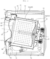
- a washing machine includes a casing 10 forming an exterior appearance of the washing machine, a tub 30 for containing wash water, and a drum 40 rotatably provided in the tub 30 and accommodating laundry.
- the washing machine may include a motor (hereinafter, referred to as a “driving unit") for rotating the drum 40.
- a front panel 11 having a laundry entry hole 12 formed therein is disposed on a front surface of the casing 10.
- a door 20 for opening and closing the laundry entry hole 12 is disposed on the front panel 11, and a dispenser 14 for supplying detergent may be installed on the front panel 11.
- a water supply valve 15, a water supply pipe 16, and a water supply hose 17 are installed in the casing 10 so that wash water supplied after passing through the water supply valve 15 and the water supply pipe 16 is mixed with detergent in the dispenser 14 and is then supplied to the tub 30 through the water supply hose 17.
- a direct water supply pipe 18 may be connected to the water supply valve 15 so that wash water is supplied directly to the tub 30 through the direct water supply pipe 18 without being mixed with detergent.
- a pump 70 and a distribution pipe 80 may be installed.
- the pump 70 and the tub 30 may be connected via a discharge hose 72, and the distribution pipe 80 and the pump 70 may be connected directly to each other or connected via a circulation pipe 86. Accordingly, if the pump 70 operates, wash water contained in the tub 30 may be sprayed into the drum 40 through the distribution pipe 80 and circulate.
- the pump 70 may be connected to a drain pipe 74 and discharge wash water to the outside through the drain pipe 74.
- the pump 70 of the washing machine functions a drain pump for discharging wash water to the outside and as a circulation pump for circulating wash water.
- a drain pump and a circulation pump may be installed individually, and, in this case, it is obvious that the drain pump is connected to the drain pipe 74 and the circulation pump is connected to the circulation pipe 86.
- the tub 30 may be formed as a single tub body or may be formed as a combination of a first tub body 30a and a second tub body 30b coupled thereto.
- first tub body 30a and the second tub body 30b are coupled to form the tub 30.
- first tub body 30a is referred to as a "tub" 30.
- the tub 30 is disposed in the casing 10, and an opening 32 (see FIG. 4 ) is formed at the front of the tub 30 to correspond to the laundry entry hole 12 formed in the front panel 11.
- the drum 40 for accommodating laundry may be rotatably provided in the tub 30.
- the drum 40 receives laundry, and is disposed such that an entrance hole through which laundry is loaded is disposed at a front surface.
- the drum 40 is rotated about an approximately horizontal rotation center line.
- "horizontal” does not refer to the mathematical definition thereof. That is, even in the case where the rotation center line is inclined at a predetermined angle relative to a horizontal state, the axis is more like in the horizontal state than in a vertical state, and thus, it is considered that the rotation center line is substantially horizontal.
- a plurality of through holes may be formed in the drum 40 so as to introduce water contained in the tub 30 into the drum 40.
- a plurality of lifter may be provided on an inner surface of the drum 40.
- the plurality of liters may be disposed at a predetermined angle relative to the center of the drum 40.
- a driving unit 50 for rotating the drum 40 may be further provided.
- a driving shaft to be rotated by the driving unit 50 may penetrate the rear of the tub 30 to be coupled to the drum 40.
- the driving unit 50 includes a direct drive wash motor
- the wash motor may include a stator fixed to the rear of the tub 30, and a rotor rotating by a magnetic force acting in relation with the stator.
- the driving shaft 38a may rotate integrally with the rotor.
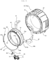
- the washing machine includes a gasket 60 for connecting the casing 10 and the tub 30, a plurality nozzle 66 and 67 (see FIG. 6 ) for spraying water into the drum 40, the pump 70 for pumping water discharged from the tub 30, and a distribution pipe 80 for guiding the water pumped by the pump 70 to the nozzle 66 and 67.
- the washing machine may include a balancer 90 disposed at a front surface 31 of the tub 30, and the circulation pipe 86 for guiding the water pumped by the pump 70 to the distribution pipe 80.
- the gasket 60 includes a gasket body 61 and 62 that forms a passage 60P connecting the laundry entry hole 12 of the casing 10 and the opening 32 of the tub 30.
- An inner circumferential surface facing the central direction of the gasket body 61 and 62 of the gasket 60 may be referred to as an inner circumferential surface 62, and an outer circumferential surface opposite thereto may be referred to the inner circumferential surface 61.
- the inner circumferential surface 62 of the gasket body may form the passage 60P connecting the laundry entry hole 12 and the opening 32.
- the outer circumferential surface 61 of the gasket body may oppose the inner circumferential surface of the balancer 90.
- the outer circumferential surface of the gasket body of the gasket 60 may oppose the distribution pipe 80.
- the gasket 60 is disposed between an edge defining the entry hole 12 of the front panel 11 and an edge defining the opening 32 of the tub 30, and accordingly, a leakage of wash water contained in the tub 30 is prevented.
- the gasket 60 is formed of a flexible substance such as rubber and has an approximate cylindrical shape (hereinafter, referred to as an annular shape).
- the gasket 60 may be formed of a substance such as Ethylene Propylene Diene Monomer (EPDM), Thermo Plastic Elastomer (TPE), or the like, but aspects of the present invention are not limited thereto.
- EPDM Ethylene Propylene Diene Monomer
- TPE Thermo Plastic Elastomer
- the gasket body 61 and 62 connecting the front and rear boundaries of the gasket 60 forms the laundry entry passage 60P. If a space between the tub and the front panel are sealed and the door 20 is closed, the door 20 and the front end of the gasket 60 are tightly brought into contact with each other and the space between the door 20 and the gasket 60 is sealed, and therefore, leakage of wash water is prevented.
- a front end part and a rear end part of the gasket 60 are annular, and the gasket 60 has a tubular shape extending from the front end part to the rear end part.
- the front end part of the gasket 60 is fixed to the casing 10, and the rear end part is fixed to an entrance hole circumference 33 of the tub 30.
- the gasket 60 may be formed of a flexible or elastic substance.
- the gasket 60 may be formed of natural rubber or synthetic resin.
- the gasket 60 may include a casing coupling part 68a coupled to a circumference of the entry hole 12 of the casing 10, a tub coupling part 68b coupled to a circumference of the entrance hole circumference 33 of the tub 30, and a gasket body 61 and 62 extending between the casing coupling part 68a and the tub coupling part 68b.
- the casing coupling part 68a and the tub coupling part 68b have an annular shape.
- the gasket body 61 and 62 may include an annular front end part connected to the casing coupling part 68a and an annular rear end part connected to the tub coupling part 68b, and have a tubular shape extending from the front end part to the rear end part.
- the circumference of the entry hole 12 of the front panel 11 is rolled outwardly, and the casing coupling part 68 may be fitted into a concave area formed by the outward rolled portion.
- An annular groove to be wound by a wire may be formed in the casing coupling part 61. After the wire winds around the groove 61r, both ends of the wire are bound, and therefore, the casing coupling part 61 is tightly fixed to the circumference of the entrance hole 12h.
- An annular groove to be wound by a wire may be formed in the tub coupling part 68b. The wire winds around the groove, and both ends of the wire are bounded, and accordingly, the tub coupling part 68b may be tightly coupled to the entrance hole circumference 33 of the tub 30.
- the gasket 60 may include a folding part 61b between the casing coupling part 68a and the tub coupling part 68b (or the gasket body 61 and 62), and the folding part 61b (hereinafter, referred to as an "inner circumferential part")is folded as the tub 30 moves in a direction of eccentricity (or a radial direction).
- the gasket body 61 and 62 may include: an annular rim part 61a extending from the casing 10 (or the casing coupling part 68a) toward the tub 30 (or the tub coupling part 68b) (or toward the rear); an inner circumferential part 61b bent outward from the first flat part 61a and extending toward the casing 10; and an outer circumferential part bent outward from the inner circumferential part 61b, extending toward the tub 30, and having a diameter greater than a diameter of the rim part 61 and a diameter of the inner circumferential part 61b.
- the gasket 60 may include an outer door contact portion 683 that is bent from the front of the gasket body 61 and 62 toward a outer side, so that the outer door contact portion 683 can be brought into a rear surface of the door 20 in the outside of the entry hole 12 in a state in which the door 20 is closed.
- the casing coupling part 68a may have the aforementioned groove that is formed at a portion extending from the outer side of the outer door contact portion 683.
- the gasket 60 may further include an inner door contact portion 681 that is bent inward from the front of the gasket body 61 and 62k, so that the inner door contact portion 681 can be brought into contact with a rear surface (preferably, the window 22) of the door 20 in the inside of the entry hole 12 in a state in which the door 20 is closed.
- a rotating direction (hereinafter, referred to as an "eccentric direction") has a radial directional component.
- the front side of the inner circumferential part 61b and the front side of the outer circumferential part 61c may be folded or unfolded when the tub 30 moves in an eccentric direction. If a portion of the inner circumferential part 61b is folded when the center of the tub 30 moves in the eccentric direction, a distance between the inner circumferential part 61b and the outer circumferential part 61c is reduced at the folded portion, whilst a distance the inner circumferential part 61b and the outer circumferential part 61c is increased at an unfolded portion of the inner circumferential part 61b.
- the plurality of nozzle 66 and 67 may be provided in plural on the inner circumferential surface 62 of the gasket 60.
- the plurality of nozzles 66 and 67 may include a plurality of upper nozzles 66a and 67a, and a plurality of lower nozzles 66b and 67b disposed lower than the upper nozzles 66a and 67a.
- the plurality of upper nozzles 66a and 67a may be disposed higher than the center of the gasket 60, and the plurality of lower nozzles 66b and 67b may be disposed lower than the center of the gasket 60.
- a plurality of nozzles 66 and 67 may include a first nozzle 66 disposed in the first area and a second nozzle 67 disposed in the second area.
- the first nozzle 66 may be disposed on the left side of the inner circumferential surface 62 of the gasket body, and the second nozzle 67 may be disposed on the right side of the inner circumferential surface 62 of the gasket body.
- Each of the first nozzle 66 and the second nozzle 67 may be provided in plural. In the embodiment of the present invention, two first nozzles 66 and two second nozzles 67 are provided, but aspects of the present invention are not limited thereto.
- the first nozzle 66 may include a first upper nozzle 66a and a first lower nozzle 66b that are vertically disposed in the first area.
- the first lower nozzle 66b may be disposed lower than the center O of the gasket 60, and the first upper nozzle 66a may be disposed higher than the first lower nozzle 66b.
- the first upper nozzle 66a may be disposed higher than the center O of the gasket 60.
- the second nozzle 67 may include a second upper nozzle 67a ad a second lower nozzle 67b that are vertically disposed in the second area.
- the second lower nozzle 67b may be disposed lower than the center O of the gasket 60, and the second upper nozzle 67a may be disposed higher than the second lower nozzle 67b.
- the second upper nozzle 67a may be disposed higher than the center O of the gasket 60.
- the first and second lower nozzles 66b and 67b may spray circulating water into the drum 40 in an upward direction.
- the first and second upper nozzles 66a and 67a may spray circulating water into the drum 40 in a downward direction.
- the circulating water refers to water that is discharged from the tub 30, pumped by the pump 70, guided to the distribution pipe 80, and sprayed into the drum 40 through the nozzle 66 and 67.
- a direct nozzle for spraying water into the drum 40, and a direct water supply pipe 18 for guiding water supplied through a water supply unit to the direct nozzle.
- the direct nozzle may be a whirl nozzle or a spray nozzle, but aspects of the present invention are not necessarily limited thereto.
- the direct nozzle When viewed from the front, the direct nozzle may be disposed on a vertical line OV.
- a window 22 may protrude toward the drum 40 further than the direct nozzle.
- a water stream sprayed through the direct nozzle may touch the window 22, and, in this case, the effect of cleaning the window 22 may be achieved.
- the gasket 60 includes a plurality of port receiving pipes 63 and 64 communicating with the nozzle 66 and 67.
- the plurality of port receiving pipes 63 and 64 may be formed to protrude from the outer circumferential surface 61 of the gasket body.
- a plurality of outlet ports 83 and 84 described in the following are inserted into the plurality of port receiving pipes 63 and 64, and the plurality of port receiving pipes 63 and 64 is formed to protrude from the outer circumferential surface 61 of the gasket body, and accordingly, water supplied from the distribution pipe 80 to the plurality of nozzles 66 and 67 is prevented from leaking through between the plurality of port receiving pipes 62 and 63 and the plurality of outlet ports 83 and 84.
- the plurality of port receiving pipes 63 and 64 may be in number corresponding to the number of the nozzles 66 and 67.
- the plurality of port receiving pipes 63 and 64 may include a first port receiving pipe 63 disposed in the first area and a second port receiving pipe 64 disposed in the second area.
- the first port receiving pipe 63 may communicate with the first nozzle 66, and the second port receiving pipe 64 may communicate with the second nozzle 67.
- the first port receiving pipe 63 may be disposed on the left side of the outer circumferential surface 61 of the gasket body, and the second port receiving pipe 64 may be disposed on the right side of the outer circumferential surface of the gasket body.
- the first port receiving pipe 63 may include a first upper port receiving pipe 63a and a first lower port receiving pipe 63b that are vertically disposed in the first area.
- the first lower port receiving pipe 63b is disposed lower than the center O of the gasket 60, and the first upper port receiving pipe 63a may be disposed higher than the first lower port receiving pipe 63b.
- the first upper port receiving pipe 63a may be disposed higher than the center O of the gasket 60.
- the first lower port receiving pipe 63b communicates with the first lower nozzle 66b, and the first upper port receiving pipe 63a communicate with the first upper nozzle 66a.
- the first upper port receiving pipe 63a and the first lower port receiving pipe 63b may protrude in directions parallel to each other.
- the second port receiving pipe 64 may include a second upper port receiving pipe 64a and a second lower port receiving pipe 64b that are vertically disposed in the second area.
- the second lower port receiving pipe 64b is disposed lower than the center O of the gasket 60, and the second upper port receiving pipe 64a may be disposed higher than the second lower port receiving pipe 64b.
- the second upper port receiving pipe 64a may be disposed higher than the center O of the gasket 60.
- the second lower port receiving pipe 64b communicates with the second lower nozzle 67b, and the second upper port receiving pipe 64a communicates with the second upper nozzle 67a.
- the second upper port receiving pipe 64a and the second lower port receiving pipe 64b may protrude in directions parallel to each other.
- the upper nozzles 66a and 67a of the first and second nozzles 66 and 67, and the upper port receiving pipes 63a and 64a of the first and second port receiving pipes 63 and 64 may be disposed higher than a horizontal line OH passing through the center O of the gasket 60.
- the lower nozzles 66b and 67b of the first and second nozzles 66 and 67, and the lower port receiving pipes 63b and 64b of the first and second port receiving pipes 63 and 64 may be disposed lower than the horizontal line OH passing through the center O of the gasket 60.
- a distance between each of the lower nozzles 66b and 67b or the lower port receiving pipes 63b and 64b and the horizontal line OH passing through the center O of the gasket 60 may be smaller than a distance between each of the upper nozzles 66a and 67a or the upper port receiving pipes 63a and 64a and the horizontal line OH passing through the center O of the gasket 60.
- Laundry received in the drum 40 is piled up at a lower side in the drum 40 due to the weight of gravity.
- the lower nozzles 66b and 67b need to be disposed at a height spaced a considerable distance from the lowest point in the gasket 60.
- an angle formed by each of the lower nozzles 66b and 67b, the center O of the gasket 60, and the lowest point in the gasket 60 may be 45° or greater.
- an angle formed by the lower port receiving pipes 63b and 64b, the center O of the gasket 60, and the lowest point in the gasket 60 may be 45° or greater.
- the upper nozzles 66a and 67a need to be spaced a considerable distance from the lower nozzles 66b and 67b.
- an angle formed by the upper nozzle 66a and 67a, the center O of the gasket 60, and the horizontal line OH passing through the center O of the gasket 60 may be 30° or greater.
- an angle formed by each of the upper port receiving pipes 63a and 64a, the center O of the gasket 60, and the horizontal line OH passing through the center O of the gasket 60 may be 30° or greater.
- a plurality of protruding part 65 may be formed in the inner circumferential surface 62 of the gasket at portion respectively corresponding to the plurality of port receiving pipes 63 and 64 to protrude inward, and the plurality of nozzles 66 and 67 may be formed at the protruding parts 65.
- the protruding part 65 may include a first protruding part 65a, a second protruding part 65b, a third protruding part 65c, and a fourth protruding part 65d protruding inwardly at portions that respectively correspond to the first upper and lower port receiving pipes 63a and 63b and the second upper and lower port receiving pipes 64a and 64b.
- the first upper and lower nozzles 66a and 66b and the second upper and lower nozzles 67a and 67b may be respectively formed at the first protruding part 65a, the second protruding part 65b, the third protruding part 65c, and the fourth protruding part 65d.
- the distribution pipe 80 includes the transport conduit 81 and 82 for guiding water pumped by the pump 70, and the outlet ports 83 and 84 protruding from the transport conduit 81 and 82 toward the gasket 60 and coupled to the port receiving pipe 63 and 64.
- the distribution pipe 80 may include an inlet port 85 introducing water discharged from the pump 70, and the transport conduit 82 may guide the water introduced through the inlet port 85 to the outlet ports 83 and 84.
- the transport conduit 81 and 82 of the distribution pipe 80 is disposed on the outer circumferential surface 61 of the gasket body.
- the distribution pipe 80 may be inserted into the gasket 60 as the plurality of outlet ports 83 and 84 are inserted into the plurality of port receiving pipes 63 and 64.
- the transport conduit 81 and 82 of the distribution pipe 80 may be disposed between the outer circumferential surface 61 of the gasket body and the balancer 90. Accordingly, the distribution pipe 80 may be installed without a need for an additional space.
- the distribution pipe 80 may be formed of synthetic resin that is harder or stiffer than the gasket 60.
- the distribution pipe 80 maintains a predetermined shape in spite of vibration occurring during operation of the washing machine, and the distribution pipe 80 is relatively rigid compared to the gasket 60 that transforms in response to vibration of the tub 30.
- the circulation pipe 86 may be flexible to transform in response to vibration of the tub 30.
- the distribution pipe 80 may be formed of synthetic resin harder or stiffer than the circulation pipe 86.
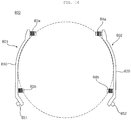
- a distribution pipe 80 of a washing machine may have an upper side 88 that is in an open ring shape. That is, the distribution pipe 80 may include an inlet port 85 introducing water pumped by the pump 70, one or more outlet ports 83 and 84 discharging the introduced water to be spayed into the drum 40 and a transport conduit 81 and 82 connecting the inlet port 85 and the outlet ports 83 and 84.
- One end of a left conduit 81 of the transport conduit 81 and 82 and one end of a right conduit 82 of the transport conduit 81 and 82 may be connected to each other at a point where the inlet port 85 is disposed, whereas the other end of the left conduit 81 and the other end of the right conduit 82 may be separated from each other.
- the inlet port 85 may be formed at a lower side of the transport conduit 81 and 82 to protrude downward, and the outlet port 83 and 84 may be formed at each of the left and right parts of the distribution pipe 80 to protrude inwardly (or toward the gasket).
- the circulation pipe 86 may be disposed between the inlet port 85 and a circulation port 87 formed in the pump 70, so that wash water in the tub is introduced into the inlet port 85 through the circulation pipe 86.
- a plurality of outlet ports 83 and 84 may include plurality of upper outlet ports 83a and 84a coupled to the upper port receiving pipe 63a and 64a of the gasket 60, and a plurality of lower outlet ports 83b and 84b coupled to the lower port receiving pipe 63b and 64b of the gasket 60.
- the plurality of upper outlet ports 83a and 84a and the plurality of lower outlet ports 83b and 84b may protrude from the transport conduit 81 and 82 toward the gasket body 61 and 62 in directions parallel to each other (which is in other words parallel directions).
- the plurality of upper outlet ports 83a and 84a and the plurality of lower outlet ports 83b and 84b may protrude in parallel with a horizontal line OH passing through the center O of the gasket 60.
- the outlet ports 83 and 84 protrude from an inner side (a surface toward the outer circumferential surface 61 of the gasket 60) of the transport conduit 81 and 82, and the outlet ports 83 and 84 are inserted into the port receiving pipes 63 and 64.
- the outlet ports 83 and 84 may guide circulating water, flowing along the transport conduit 81 and 82, to the nozzles to be thereby sprayed into the drum 40.
- the outlet ports 83 and 84 may be formed with a diameter a bit greater than an inner diameter of the port receiving pipes 63 and 64, so that the outlet ports 83 and 84 can be press-fitted into the port receiving pipes 63 and 64.
- a reaction force in a direction against the gasket 60 may be applied to a section where the outlet ports 83 and 84 are disposed in the transport conduit 81 and 82.
- the port receiving pipes 63 and 64 may be formed to protrude outward from the outer circumferential surface 61 of the gasket 60, and the outlet ports 83 and 84 may be formed with a diameter a bit greater than the inner diameter of the port receiving pipes 63 and 64.
- the outlet ports 83 and 84 include a first outlet port 83 protruding from the left conduit part 81 of the transport conduit 81 and 82 toward a vertical line OV passing through the center O of the gasket 60, and a second outlet port 84 protruding from the right conduit part 82 of the transport conduit 81 and 82 toward the vertical line OV passing through the center O of the gasket 60.
- the first outlet port 83 is inserted into the first port receiving pipe 63 to guide circulating water to the first nozzle 66
- the second outlet port 84 is inserted into the second port receiving pipe 64 to guide circulating water to the second nozzle 67.
- the first outlet port 83 may include a first lower outlet port 83b inserted into the first lower port receiving pipe 63b, and a first upper outlet port 83a disposed higher than the first lower outlet port 83b and inserted into the first upper port receiving pipe 63a.
- the second outlet port 84 may include a second lower outlet port 84b inserted into the second lower port receiving pipe 64b, and a second upper outlet port 84a disposed higher than the second lower outlet port 84b and inserted into the second upper port receiving pipe 64a.
- the inlet port 85 is connected to the transport conduit 81 and 82 at a point lower than any of the plurality of outlet ports 83 and 84.
- the inlet port 85 is connected to the transport conduit 81 and 82 at a point lower than the plurality of lower outlet ports 83b and 84b.
- the transport conduit 81 and 82 includes a first conduit part 81 forming the left side of the transport conduit 81 and 82 with reference to the inlet port 85, and a second conduit part 82 forming the right side of the transport conduit 81 and 82 with reference to the inlet port 85.
- the first conduit part 81 and the second conduit part 82 are connected at a lower side, and the inlet port 85 may protrude downward at the point where the first and second conduit parts are connected to each other.
- the transport conduit 81 and 82 may be formed in an arc shape having a central angle of 180° or greater and an open upper side, and may be bilaterally symmetrical.
- the transport conduit 81 and 82 may include the first conduit part 81 disposed in the left side, and the second conduit disposed in the right side.
- the first conduit part 81 and the second conduit part 82 may be bilaterally symmetrical about the vertical line OV passing through the center O of the gasket 60.
- the transport conduit 81 and 82 may branch water, introduced through the inlet port 85, to the left and right sides to guide upwardly. By branching the circulating water introduced through the inlet port, the transport conduit 81 and 82 may form a first sub-flow (water flowing along the first conduit part 81) and a second sub-flow (water flowing along the second conduit part 82). The first sub-flow may be sprayed into the drum 40 through the first nozzle 66, and the second sub-flow may be sprayed into the drum 40 through the second nozzle 67.
- the transport conduit 81 and 82 may be disposed between the gasket 60 and the balancer 90.
- the transport conduit 81 and 82 may be disposed in a manner in which the inner surface of the transport conduit 81 and 82 opposes the gasket 60 and the outer surface of the transport conduit 81 and 82 opposes the balancer 90.
- the port receiving pipes 63 and 64, the protruding parts 65, the nozzles 66 and 67, and the outlet ports 83 and 84 may vary in number and arrangement. In addition, it may be configured to omit the protruding parts 65 and the nozzles 66 and 67 and spray water from the outlet ports 83 and 84 into the drum 40. In addition, the nozzles 66 and 67 may be formed separately from the gasket 60 such that the nozzles 66 and 67 are coupled to the gasket 60 or spaced apart from the gasket 60.
- one end of the circulation pipe 86 is connected to the inlet port 85 protruding from the bottom of the distribution pipe 80, and the other end of the circulation pipe 86 may be connected to the circulation port 78 of the pump 70.
- the circulation pipe 86 may have a straight pipe shape.
- the circulation pipe 86 may be formed as a hose made from a flexible substance or may be formed by bending.
- the circulation pipe 86 may be formed of a substance that is flexible but able to maintain a shape thereof.
- the circulation pipe 86b may be formed of ethylene propylene diene monomer rubber (EPDM).
- EPDM ethylene propylene diene monomer rubber
- the circulation pipe 86 may include a bellows structure.
- the washing machine includes the balancer 90 disposed at the front surface 31 of the tub 30.
- the balancer 90 may be fastened to the front surface 31 of the tub 30.
- the balancer 90 is used to reduce vibration of the tub 30, and the balancer 90 is a weight body having a predetermined weight.
- the balancer 90 may include one or more balancers 90 disposed along a circumference of the front surface 31 of the tub 30.
- a balancer 90 of a washing machine may include a first balancer 91 and a second balancer 92 respectively disposed to the left and right sides of the front surface 31 of the tub 30.
- the first balancer 91 may be disposed to the left side of the gasket 60
- the second balancer 92 may be disposed to the right side of the gasket 60.
- the first balancer 91 may be disposed at an outer side of the first area
- the second balancer 92 may be disposed at an outer side of the second area.
- the first balancer 91 and the second balancer 92 may be spaced apart from each other both at an upper side and at a lower side.
- the first and second balancers 91 and 91 may be in a bilaterally symmetrical shape about the vertical line OV passing through the center O of the gasket 60, and may be disposed at positions bilaterally symmetrical about the vertical line.
- the gasket 60 includes an accommodating part 610 in which at least a portion of the transport conduit 81 and 82 is disposed.
- the gasket body 61 and 62 is divided into a front body 60a disposed on the side of the casing 10, and a rear body 60b disposed on the side of the tub 30.
- a boundary between the front body 60a and the rear body 60b of the gasket body 61 and 62 may be placed on a plane vertical to a central axis of the gasket body 61 and 62.
- the transport conduit 81 and 82 is disposed in the rear body 60b.
- the accommodating part 610 may be formed in the rear body 60b.
- the rear body 60b includes the accommodating part 610.
- the accommodating part 610 may include a boundary surface 612 extending inward from a rear end of the front body 60a.
- the boundary surface 612 is bent from the rear end of the front body 60a to extend inward.
- the boundary surface 612 is disposed on the boundary B that divides the gasket body 61 and 62 into the front body 60a and the rear body 60b.
- the boundary surface 612 is described as being included in the rear body 60b.
- the accommodating part 610 includes an opposing surface 611 extending rearward from the boundary surface 612.
- the opposing surface 611 is bent at an inner end of the boundary surface 612 to extend rearward, and opposes the inner surface of the transport conduit 81 and 82.
- the opposing surface 611 extends from the rear body 60b in a circumferential direction of the gasket body 61 and 62.
- the boundary surface 612 extends from the opposing surface 611 toward an outer side of a radial direction.
- the boundary surface 612 is connected to the front body 60a.
- the boundary B dividing the gasket body 61 and 62 into the front body 60a and the rear body 60b may be disposed on the outer circumferential part 61c. That is, the rear body 60b with the transport conduit 81 and 82 disposed therein may be disposed on the outer circumferential part 61c. Accordingly, the accommodating part 610 may be disposed in the outer circumferential part 61c.
- the tub 30 may vibrate, and the gasket 60 formed of a flexible substance may be folded or unfolded due to the vibration of the tub 30 and accordingly vibrate. Since the casing 10 and the tub 30 may be relatively rigid compared to the gasket 60, the gasket 60 is not deformed on the side of the casing 10 or on the side of the tub 30. Since the accommodating part 610 is formed to allow the transport conduit 81 and 82 to be seated therein, the accommodating part 610 may be formed on the outer circumferential surface 61 of the gasket 60 to be adjacent to the casing 10 or the tub 30.
- the transport conduit 81 and 82 since the transport conduit 81 and 82 is configured to spray water pumped by the pump to the nozzles 66 and 67 that sprays water into the drum, the transport conduit 81 and 82 may be disposed to be adjacent to the tub 30 in the embodiment of the present invention. Accordingly, the accommodating part 610 may be formed in the outer circumferential part 61c.
- the boundary surface 612 may be disposed at a rear side further than a bent portion between the inner circumferential part 61b and the rim part 61a. Accordingly, if the tub 30 vibrates in a radial direction, it is possible to prevent the intervention between the accommodating part 610 and the inner circumferential part 61b.
- the opposing surface 611 may be disposed at an outer side further than the bent portion between the inner circumferential part 61b and the rim part 61a. Accordingly, it is possible to prevent the intervention between the accommodating part 610 and the inner circumferential part 61b even when the tub 30 vibrates in a front-back direction.
- the bent portion between the inner circumferential part 61b and the rim part 61a refer to a portion bent from the rim part 61 of the inner circumferential part 61b.
- the accommodating part 610 may be formed at the most rear side (in a direction toward the tub 30) of the outer circumferential part 61c.
- the boundary surface 612 may be formed at a front side (in a direction toward the casing 10) of the accommodating part 610, and the accommodating part 610 may not have a rear surface.
- the accommodating part 610 is formed to be recessed inward further than a portion adjacent toward a front side of the accommodating part 610.
- the accommodating part 610 may be formed in a manner in which at least a portion of the outer circumferential surface 61 of the gasket 60 is recessed inward or in a manner in which a portion of the outer circumferential surface 61 of the gasket 60 protrudes (or is raised) and the accommodating part 610 is formed on one side of the protruding portion.
- a width of the transport conduit 81 and 82 in the front-back direction of the washing machine may be greater than a width of the transport conduit 81 and 82 in a radial direction of the transport conduit 81 and 82.
- the width in the front-back direction refers to a width of the inner surface of the transport conduit 81 and 82
- the width in the radial direction refers to a distance between the inner surface and the outer surface of the transport conduit 81 and 82. That is, a cross section of the transport conduit 81 and 82 may be formed in a shape in which a width of a surface of the accommodating part 610 opposing the opposing surface 611 is greater than a width of a surface of the accommodating part 610 opposing the boundary surface 612.
- the cross section of the transport conduit 81 and 82 may be in a rectangular shape.
- a long edge of the rectangular shape corresponds to the width in the front-back direction
- a short edge of the rectangular shape corresponds to the width in the radial direction. Due to this structure, it is possible to install the distribution pipe 80 even in a narrow space between the gasket 60 and the balancer 90.
- an inner surface of at least a portion of the transport conduit 81 and 82 is disposed between the front body 60a and the opposing surface 611 in the radial direction. That is, the inner surface of at least a portion of the transport conduit 81 and 82 may be disposed between the opposing surface 611 and a virtual plane extending rearward from a rear end of the front body 60a. Since the gasket body 61 and 61 has an approximately cylindrical shape, a width of the gasket body 61 and 62 in a left-right direction has the maximum value at a height equal to a height of the center O of the gasket body 61 and 62.
- the width of the gasket body 61 and 62 in the left-right direction has the maximum value on a horizontal plane passing through the center O of the gasket body 61 and 62. Accordingly, at a height equal to the height of the center O of the gasket body 61 and 62, the inner surface of the transport conduit 81 and 82 is disposed in a radial direction between the front body 60a and the opposing surface 611.
- a width of the opposing surface 611 may be formed to be equal to or greater than a width of the transport conduit 81 and 82.
- the accommodating part 610 may extend from above the center O of the gasket 60 (which can be called a horizontal line OH passing through the center O of the gasket) to below the lowest outlet ports 83b and 84b (or the lowest port receiving pipes 63b and 64b) along a circumferential direction of the gasket 60.
- the accommodating part 610 may be bilaterally symmetrical about the center O of the gasket 60. Accordingly, the lower port receiving pipes 63b and 64b may protrude from the opposing surface of the accommodating part 610.
- a distance between each of the lower port receiving pipe 63b and 64b and the horizontal line OH is shorter than a distance between each of the port receiving pipes 63a and 64a and the horizontal line OH.
- a distance between the first and second lower port receiving pipes 63b and 64b may be greater than a distance between the first and second upper port receiving pipes 63a and 64a. Accordingly, it is possible to position the distribution pipe 80 in a narrow space between the gasket and the balancer 90 as the lower port receiving pipes 63b and 64b are disposed in the accommodating part 610.
- the accommodating part 610 may extend from below the lower port receiving pipes 63b and 64b to above the upper port receiving pipes 63a and 64a along the circumferential direction of the gasket 60. In this case, not just the lower port receiving pipes 63b and 64b, but also the upper port receiving pipes 63a and 64a may protrude from the accommodating part 610.
- the accommodating part 610 may be formed from above the highest portion of the transport conduit 81 through the lowest side of the gasket 60 to above the highest portion of the opposite transport conduit 82 along a circumferential surface in a state in which the distribution pipe 80 is coupled to the gasket 60.
- the accommodating part 610 vertically extends with reference to the center O of the gasket 60 at which the gasket 60 has a maximum width in the left-right direction, it is possible to install the distribution pipe 80 even in a narrow space between the gasket 60 and the balancer 90 if only a portion of the transport conduit 81 and 82 is be seated in the accommodating part 610.
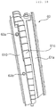
- a rib 615 may be formed in the outer circumferential surface 61 of the gasket body.
- the rib 615 may protrude from the outer circumferential surface 61 of the gasket 60 in the radial direction of the gasket 60. That is, the rib 615 may be formed to extend in a direction orthogonal to a tangent line of the outer circumferential surface 61 of the gasket body.
- the distribution pipe 80 may be disposed to have at least a portion thereof brought into contact with the rib 615. At least a portion of the transport conduit 81 and 82 in the distribution pipe 80 may be brought into contact with the rib 615.
- the rib 615 may include one or more ribs 615, and a plurality of ribs may be spaced apart from each other in the circumferential direction of the gasket body 61 and 62. Although four ribs are formed on one of the left and right sides of the gasket in FIG. 12 , the rib 615 may vary in number and arrangement.
- Friction between the distribution pipe 80 and the gasket 60 occurs due to vibration of the tub 30 and the weight of gravity. This friction may be relatively more intense occur frequently in an area around the center of the up-down direction of the gasket 60.
- a reaction force may be applied to the distribution pipe 80 and the friction may occur more intensely and frequently in an area around the outlet ports 83 and 84.
- the rib 615 may be provided between the upper port receiving pipe 63a and 64a and the lower port receiving pipe 63b and 64b.
- the rib 615 may be formed in the accommodating part 610.
- the rib 615 may protrude from the accommodating part 610 toward the transport conduit 81 and 82.
- the rib 615 may include either or both of a first protrusion 615a formed in the opposing surface 611 of the accommodating part 610 and a second protrusion 615b formed in the boundary surface 612.
- a first protrusion 615a formed in the opposing surface 611 of the accommodating part 610
- a second protrusion 615b formed in the boundary surface 612.
- the first protrusion 615a may protrude from the opposing surface 611 of the accommodating part 610 toward an outer side of a radial direction of the gasket body, and the second protrusion 615b may protrude from the boundary surface 612 toward the tub 30.
- the first protrusion 615a may come into contact with an inner surface of the transport conduit 81 and 82 opposing the opposing surface 611, and the second protrusion 615b may come into contact with the front surface of the transport conduit 81 and 82 opposing the boundary surface 612 of the accommodating part 610.
- Vibration of the tub 30 may cause the inner circumferential part 61b of the gasket 60 to be folded or unfolded, or the vibration may be delivered.
- the rib 615 may be formed. Accordingly, the rib 615 may be formed in the opposing surface 611 and the boundary surface 612 of the accommodating part 610 in which friction occurs due to vibration of the tub 30 and the gasket 60.
- the gasket 60 since the gasket 60 is coupled to the tub 30, vibration of relative small amplitude may occurs at a position adjacent to the tub 30, the outer circumferential surface 61 of the gasket 60 (or the accommodating part 610) may not have a portion that comes into contact with the distribution pipe 80 toward the tub 30, and the front surface 31 of the tub 30 and the distribution pipe 80 may be spaced apart from each other, and therefore, even if a rib is not installed between the tub 30 and the distribution pipe 80, abrasion of the gasket 60 or the like may not occur.
- the first protrusion 615a and the second protrusion 615b may be formed at different latitudes to be spaced apart each other. Alternatively, the first protrusion 615a and the second protrusion 615b may be formed at the same latitude to be spaced apart from each other or continue.
- latitude refers to an angle relative to a horizontal line OH passing through the center O of the gasket 60 (which is a straight line orthogonal to the vertical line OV, when seen from the front). A latitude on the left side of the gasket is measured in the clock-wise direction, and a latitude on the right side of the gasket is measured in the counter clockwise-direction. Accordingly, the term “latitude” may be integrated to be similar as used in a map.
- the rib 615 may include a connecting protrusion 615c formed between the first protrusion 615a and the second protrusion 615b and connecting the first protrusion 615a and the second protrusion 615b.
- the connecting protrusion 615c may be formed between the first protrusion 615a and the second protrusion 615b so that an edge having an angle of 90° between the first protrusion 615a and the second protrusion 615b may not be formed.
- the transport conduit 81 and 82 may be brought into contact with the connecting protrusion 615. In this case, abrasion of the first protrusion 615a and the second protrusion 615b may be delayed.
- the rib 615 may be formed integrally with the gasket 60 using the same substance of the gasket 60.
- an accommodating part 610 of a washing machine may be formed at one side (a rear side) of a raised portion 61d that corresponds to a outwardly protruding portion of the outer circumferential surface 61 of the gasket 60.
- the raised portion 61 may be formed at a front side from the outer circumferential surface 61c
- the accommodating part 610 may be formed at a rear side of the outer circumferential part 61c.
- the raised portion 61d may be disposed in the front body 60a.
- the raised portion 71d may be formed on both the left and right sides from the upper side of the center O of the gasket 60 to the lowest port receiving pipes 63b and 64b.
- the accommodating part 610 may include a first accommodating part 610a disposed in the first area and a second accommodating part 610b disposed in the second area. That is, the accommodating part 610 may include the first accommodating part 610a formed in the left-side outer circumferential surface 61 of the gasket body, and a second accommodating part 610b formed in the right-side outer circumferential surface 61 of the gasket body 61 and 62.
- the lowest port receiving pipes 63b and 64b may protrude from the opposing surface 611 of the accommodating part 610. More specifically, the first lower port receiving pipe 63b may protrude from the opposing surface 611 of the first accommodating part 610a, and the second lower port receiving pipe 64b may protrude from the opposing surface 611 of the second accommodating part 610b.
- the left part of the transport conduit 81 and 82 may have at least a portion disposed between the outer circumferential surface 61 of the gasket 60 and the first balancer 91 and disposed in the first accommodating part 610a.
- the right part of the transport conduit 81 and 82 may have at least a portion disposed between the outer circumferential surface 61 of the gasket 60 and the second balancer 92 and disposed in the second accommodating part 610b.
- At least a portion of the first conduit part 81 may be disposed between the opposing surface 611 of the first accommodating part 610a and the first balancer 91. At least a portion of the second conduit part 82 may be disposed between the opposing surface 611 of the second accommodating part 610b and the second balancer 92.
- one or more ribs 615 may be formed in each of the first accommodating part 610a and the second accommodating part 610b.
- at least a portion of the left part 81 of the transport conduit 81 and 82 may be brought into contact with a rib 615 formed in the first accommodating part 610
- at least a portion of the right part 82 of the transport conduit 81 and 82 may be brought into contact with a rib 615 formed in the second accommodating part 610b.
- the rib 615 may be formed in the first accommodating part and provided in plural between the first upper port receiving pipe 63a and the first lower part receiving pipe 63b along the circumferential direction of the gasket 60.
- the rib 615 may be formed in the second accommodating part and provided in plural between the second upper port receiving pipe 64a and the second lower part receiving pipe 64b along the circumferential direction of the gasket 60.
- the accommodating part 610 is formed by the raiser portion 61d, the aforementioned boundary surface 612 of the accommodating part 610 is a surface that connects the opposing surface 611 of the accommodating part 610 and the riser portion 61d.
- the transport conduit 81 and 82 may be disposed in the accommodating part.
- the inner surface of the transport conduit 81 and 82 that is, a surface toward the gasket 60, may have a portion that is seated in the opposing surface 611 or is brought into contact with the first protrusion 615a.
- a portion on the front surface of the transport conduit 81 and 82 may be seated in the boundary surface 612 of the accommodating part or is brought into contact with the second protrusion 615b. Since the tub 30 is disposed at the rear of the transport conduit 81 and 82, a portion of the transport conduit 81 and 82 is allowed to be seated in a space between the opposing surface 611 and the boundary surface 612 of the accommodating part.
- a washing machine according to a second embodiment of the present invention is different from the washing machine according to the first embodiment in terms of structures of the balancer 90 and the distribution pipe 800.
- the washing machine according to the second embodiment of the present invention may include a balancer 90, which is disposed at a front surface 31 of the tub 30 and separated vertically, and a distribution pipe 800, which includes a first distribution pipe 801 and a second distribution pipe 802 respectively provided on the left and right sides of the outer circumferential surface 61 of the gasket body.
- a balancer 90 which is disposed at a front surface 31 of the tub 30 and separated vertically
- a distribution pipe 800 which includes a first distribution pipe 801 and a second distribution pipe 802 respectively provided on the left and right sides of the outer circumferential surface 61 of the gasket body.
- the balancer according to the second embodiment may include an upper balancer 93 at an upper side of a gasket 60, and a lower balancer 94 at a lower side of the gasket 60.
- the first and second distribution pipes 801 and 802 are connected to a pump 70 through separate circulation pipes 861 and 862, respectively.
- the first and second distribution pipes 801 and 802 may supply water, pumped by the pump 70, to a first nozzle and a second nozzle.
- a first inlet port 851 and a second inlet port 852 may be formed at lower sides of the first distribution pipe 801 and the second distribution pipe 802, respectively.
- Each of the first and second distribution pipes 801 and 802 may respectively include upper and lower outlet ports 830 and 840.
- the first and second distribution pipes 801 and 802 respectively include a first transport conduit 810 and a second transport conduit 820 to guide circulating water, supplied through the inlet ports 851 and 852, to the outlet ports 830 and 840.
- the first transport conduit 810 is disposed on an outer circumferential surface of a first area
- the second transport conduit 820 is disposed on an outer circumferential surface of a second area. At least a portion of the first conduit 810 and at least a portion of the second transport conduit 820 may be respectively disposed in a first accommodating part 610a and a second accommodating part 610b.
- the first distribution pipe 801 may include a first upper outlet port 83a disposed higher than the center O of the gasket 60, and a first lower outlet port 83b disposed lower than the center O of the gasket 60 and higher than the first inlet port 851.
- the second distribution pipe 802 may include a second upper outlet port 84a disposed higher than the center O of the gasket 60, and a second lower outlet port 84b disposed lower than the center O of the gasket 60 and higher than the second inlet port 852.
- the outlet ports 83a, 83b, 84a, and 84b may be connected to the first upper and lower port receiving pipes 63a and 63b and the second upper and lower port receiving pipes 64a and 64b to spray or discharge circulating water into a drum 40.
- a washing machine according to a third embodiment of the present invention is different from the first embodiment in terms of the shape of a gasket 60.
- Other configurations and operations are identical or similar to the first embodiment, and thus, like components are given like reference numerals and a detailed description thereof is herein omitted.
- the washing machine according to the third embodiment may include an accommodating part 610 formed inward on an outer circumferential surface 61 of the gasket 60 to allow at least a portion of a transport conduit 81 and 82 to be positioned therein.
- the accommodating part 610 may be formed in a manner in which at least a portion of the outer circumferential surface is recessed inward.
- the accommodating part 610 may be formed from above the highest portion of the first conduit part 81 through the lowest side of the gasket 60 to above the highest portion of the second conduit part 82 along a circumferential surface in a state in which the distribution 80 is coupled to the gasket 60.
- the accommodating part 610 may be formed from above the highest portion of the transport conduit 81 and 82 to below the lowest outlet ports 83b and 84b (or the lowest port receiving pipes 63b and 64b), and the accommodating part 610 may be bilaterally symmetrical about the center O of the gasket 60.
- a rib 615 as the same as the rib 615 in the first embodiment may be formed.
Landscapes
- Engineering & Computer Science (AREA)
- Textile Engineering (AREA)
- Detail Structures Of Washing Machines And Dryers (AREA)
Abstract
Description
- The present invention relates to a washing machine and particularly to a washing machine having nozzles that spray water, discharged from a tub and circulated along a circulation pipe, into a drum.
- In general, a washing machine is an apparatus for removing a contaminant adhered to clothes, bedding, etc. (hereinafter, referred to as 'the laundry') using a chemical disintegration of water and a detergent and a physical operation such as a friction between water and the laundry. The washing machine includes a tub containing water, and a drum rotatably provided in the tub to accommodate laundry.
- Korean Patent Application Publication No.
10-2011-0040180 - The related art discloses a washing machine having two spray nozzles, but the washing machine is not capable of uniformly wetting laundry since spray directions are limited. In particular, although various new technologies for controlling rotation of the drum have been developed to provide diversity to movement of laundry loaded in the drum, it is hard to expect remarkable improvement in performance using the conventional structure.
- In addition, the conventional technology has a complex structure because the spray nozzles need to be coupled to the gasket by passing the connectors through the gasket, the spray nozzles connected to the circulation pump need to be in number corresponding to the number of spray nozzles, and a plurality of flow paths and the plurality connectors need to be coupled, respectively. In addition, the manufacturing procedure is bothersome due to the assembling process.
- In addition, the plurality of spray paths may be interfered with any other structure around the tub, such as a balancer. In order to avoid such interference, the structure and position of the balancer or the like are limited.
- In addition, there are many portions for connecting the pump, the spray paths, the connectors, and the spray nozzles, and wash water is likely to leak through the portions. In addition, there is also a hygiene issue because of solidification of detergent in the wash water or pigmentation of a contaminant.
- In order to solve the above problem, a method for guiding circulating water, discharged from a circulation pump to a plurality of nozzles is actively under development.
- However, there may be intervention between a pipe for guiding the circulating water to the plurality of nozzles and a structure such as a balancer.
- In addition, abrasion of the gasket may occur due to friction between the pipe for guiding the circulating water to the plurality of nozzles ad the gasket.
- An object of the present invention is to provide a washing machine having a plurality of nozzles for uniformly spraying water discharged from a tub to thereby uniformly wet laundry, and simplifying a connection structure and an assembling process between a pump and the plurality of nozzles.
- Another object of the present invention is to provide a washing machine that avoids intervention between a circulating water supply pipe for guiding water pumped by a pump to nozzles and any other structure around a gasket.
- Yet another object of the present invention is to provide a washing machine that prevents the circulating water supply pipe from being separated from the gasket due to deformation of the gasket that can be caused by vibration of the tub upon rotation of a drum.
- Yet another object of the present invention is to provide a washing machine that prevents abrasion of a basket due to friction between the circulating water supply pipe and the gasket.
- Objects of the present invention should not be limited to the aforementioned objects and other unmentioned objects will be clearly understood by those skilled in the art from the following description.
- In order to achieve the above objects, a washing machine according to an embodiment of the present invention includes: a gasket, wherein the gasket includes a gasket body, forming a passage between a laundry entry hole formed in a casing and an opening formed in a tub, and a plurality of nozzles spraying water into a drum; and a distribution pipe supplying water pumped by a pump to the plurality of nozzles.
- The laundry entry hole is formed in a front surface of the casing.
- The tub is disposed in the casing. The opening is formed in a front surface of the tub.
- The plurality of nozzles is provided on an inner circumferential surface of the gasket body.
- The distribution pipe includes a transport conduit disposed on an outer circumferential surface of the gasket, and a plurality of outlet ports protruding from the transport conduit toward the gasket body. The transport conduit guides water pumped by the pump. The plurality of outlet ports supplies water to the plurality of nozzles.
- The gasket body is divided into a front body positioned on the side of the casing and a rear body positioned on the side of the tub.
- The transport conduit is disposed in the rear body. The rear body comprises an accommodating part in which at least a portion of the transport conduit is disposed.
- The accommodating part includes a boundary surface bent from a rear end of the front body to extend inward, and a opposing surface bent from an inner end of the boundary surface to extend rearward and opposing the transport conduit. The opposing surface opposes the transport conduit.
- The gasket body may include a rim part extending from the casing toward the tub, an inner circumferential part bent outward from the rim part to extend toward the casing, and an outer circumferential part bent outward from the inner circumferential part to extend toward the tub.
- The outer circumferential part may have a diameter greater than a diameter of the inner circumferential part.
- The rear body may be disposed in the outer circumferential part.
- The boundary surface may be disposed at a rear side further than a portion bent from the rim part of the inner circumferential part.
- The opposing surface may be disposed at an outer side than a portion bent from the rim part of the inner circumferential part.
- The transport conduit may include an inner surface that opposes the outer circumferential surface of the gasket body. An inner surface of at least a portion of the transport conduit may be disposed between the opposing surface and a virtual plane that extends rearward from a rear end of the front body.
- When the gasket body is bilaterally divided into a first area and a second area, the accommodating part includes a first accommodating part disposed in the first area, and a second accommodating part disposed in the second area.
- The gasket may include a plurality of port receiving pipes protruding from the outer circumferential surface of the gasket body and communicating with the plurality of nozzles, respectively.
- The plurality of port receiving pipes may include a first upper port receiving pipe and a first lower port receiving pipe that are vertically disposed in the first area.
- The first lower port receiving pipe may be disposed lower than a horizontal line that passes through a center of the gasket.
- The first upper port receiving pipe may be disposed higher than the horizontal line.
- A distance between the first lower port receiving pipe and the horizontal line may be shorter than a distance between the first upper port receiving pipe and the horizontal line.
- The first accommodating part may extend from above at least the horizontal line to below the first lower port receiving pipe along a circumferential direction of the gasket.
- The first lower port receiving pipe may protrude from the opposing surface of the first accommodating part.
- The first lower port receiving pipe and the first upper port receiving pipe may protrude in directions parallel to each other.
- The first lower outlet port and the first upper outlet port may protrude in directions parallel to each other.
- The plurality of port receiving pipes may comprise a second upper port receiving pipe and a second lower port receiving pipe that are vertically disposed in the second area.
- The plurality of outlet ports may include a second upper outlet port coupled to the second upper port receiving pipe, and a second lower outlet port coupled to the second lower port receiving pipe.
- The distribution pipe may include an inlet port protruding downward from the transport conduit at a point lower than the first and second lower outlet ports and introducing water pumped by the pump.
- The transport conduit may include: a first conduit part disposed on an outer circumferential surface of the first area, and guiding water, introduced through the inlet port, to the first lower outlet port and the first upper outlet port, sequentially; and a second conduit part disposed on an outer circumferential surface of the second area, and guiding water, introduced through the inlet port, to the second lower outlet port and the second upper outlet port, sequentially.
- The washing machine may further include a balancer disposed at the front surface of the tub. The balancer may include a first balancer disposed at an outer side of the first area and a second balancer disposed at an outer side of the second area.
- At least a portion of the transport conduit may be disposed between the gasket and the balancer. At least a portion of the first conduit part may be disposed between the opposing surface of the first accommodating part and the first balancer. At least a portion of the second conduit part may be disposed between the opposing surface of the second accommodating part and the second balancer.
- The distribution pipe may include: a first distribution pipe supplying water, pumped by the pump, to a first upper nozzle and a first lower nozzle that communicate with the first upper port receiving pipe and the first lower port receiving pipe, respectively; and a second distribution pipe supplying water, pumped by the pump, to a second upper nozzle and a second lower nozzle that communicating with the second upper port receiving pipe and the second lower port receiving pipe, respectively.
- The first distribution pipe may include a first transport conduit disposed on the outer circumferential surface of the first area, and a first inlet port introducing water pumped by the pump and disposed below the first lower outlet port to protrude from the first transport conduit, and the first upper and lower outlet ports.
- The second distribution pipe may include a second transport conduit disposed on the outer circumferential surface of the second area, a second inlet port introducing water pumped by the pump and disposed below the second lower outlet port to protrude from the second transport conduit, and the second upper and lower outlet ports.
- The transport conduit may be formed to have a width in a front-rear direction that is greater than a width in a radial direction.
- A width of the recessed portion in the front-back direction may be equal to or greater than the width of the transport conduit in the front-back direction.
- The gasket may include a rib protruding from the accommodating part toward the transport conduit.
- The rib may protrude at least one of the opposing surface or the boundary surface.
- The rib may include a first protrusion protruding from the opposing surface in a radial direction of the gasket body, and a second protrusion protruding from the boundary surface toward the tub. The rib may include a connecting protrusion formed between the first protrusion and the second protrusion. The connecting protrusion may connect the first protrusion and the second protrusion.
- The rib may include a plurality of ribs.
- The plurality of ribs may be spaced apart in a circumferential direction of the gasket body.
- The rib may be disposed between the lower port receiving pipe and the upper port receiving pipe.
- The details of other embodiments are included in the following description and the accompanying drawings
- The washing machine of the present invention may have one or more effects, as below.
- First, a plurality of nozzles is provided on an inner circumferential surface of a gasket, and a distribution pipe connects the pump and the plurality of nozzles so as to supply water pumped by the pump to the plurality of nozzles, and thus, there is an advantageous effect of simplifying a connection structure and an assembling process between the pump and the plurality of nozzles.
- Second, the rear body of the gasket body includes an accommodating part, which includes a boundary surface bent from a rear end of the front body to extend inward and a opposing surface bent from an inner end of the boundary surface to extend rearward and opposing the transport conduit, and at least a portion of the transport conduit of the distribution pipe is disposed in the accommodating part, and therefore, it is possible to avoid intervention between the distribution pipe and any other structure around the gasket, such as the balancer. In addition, as the intervention between the distribution pipe and other structures, the whole washing machine may be reduced in size.
- Third, the gasket may include a rim part extending from the casing toward the tub, an inner circumferential part bent outward from the rim part to extend toward the casing, and an outer circumferential part bent outward from the inner circumferential part to extend toward the tub. A shape of the inner circumferential surface may change repeatedly due to vibration of the tub upon rotation of the drum. Since the accommodating part is disposed on the outer circumferential surface, it is possible to smoothly spray water into the drum through the nozzles and prevent separation the distribution pipe due to deformation of the gasket.
- Fourth, the gasket includes a rib protruding from the accommodating part toward the transport conduit, and thus, it is possible to prevent abrasion of the gasket due to friction between the distribution pipe and the gasket.
- Effects of the present invention should not be limited to the aforementioned effects and other unmentioned effects will be clearly understood by those skilled in the art from the claims.
- The embodiments will be described in detail with reference to the following drawings in which like reference numerals refer to like elements wherein:
-
FIG. 1 is a perspective view of a washing machine according to an embodiment of the present invention; -
FIG. 2 is a cross-sectional view of the washing machine shown inFIG. 1 ; -
FIG. 3 illustrates a portion of a washing machine according to a first embodiment of the present invention; -
FIG. 4 is an exploded perspective view of an assembly shown inFIG 3 ; -
FIG. 5 is a perspective view of a gasket shown inFIG. 4 ; -
FIG. 6 is a rear view of an assembly including the gasket and a distribution pipe shown inFIG. 4 ; -
FIG. 7 is a front view of the assembly shown inFIG. 6 ; -
FIG. 8 is a cross-sectional view taken along line I-I inFIG. 7 ; -
FIG. 9 is a front view of the distribution pipe shown inFIG. 4 ; -
FIG. 10 is a perspective view of the assembly shown inFIG. 6 ; -
FIG. 11 is a perspective view of the gasket shown inFIG. 6 ; -
FIG. 12 is an enlarged view illustrating an accommodating part of the gasket shown inFIG. 11 ; -
FIG. 13 is a cross-sectional view of a gasket cut away along line II-II inFIG. 12 ; -
FIG. 14 is a view illustrating a portion of a washing machine according to a second embodiment of the present invention; -
FIG. 15 is a view illustrating a distribution pipe and a gasket shown inFIG. 14 ; -
FIG. 16 is a front view of the distribution pipe shown inFIG. 14 ; -
FIG. 17 is a view illustrating an accommodating part of a gasket of a washing machine according to a third embodiment of the present invention; and -
FIG. 18 is a right-side view of the gasket shown inFIG. 17 . - Advantages and features of the present disclosure and methods to achieve them will become apparent from the descriptions of exemplary embodiments herein below with reference to the accompanying drawings. However, the present disclosure is not limited to exemplary embodiments disclosed herein but may be implemented in various different ways. The exemplary embodiments are provided for making the disclosure of the present disclosure thorough and for fully conveying the scope of the present disclosure to those skilled in the art. It is to be noted that the scope of the present disclosure is defined only by the claims. Like reference numerals denote like elements throughout the descriptions.
- Hereinafter, the present invention will be described in detail with reference to the accompanying drawings.
- Referring to
FIGS. 1 and2 , a washing machine according to the present invention includes acasing 10 forming an exterior appearance of the washing machine, atub 30 for containing wash water, and adrum 40 rotatably provided in thetub 30 and accommodating laundry. In addition, the washing machine may include a motor (hereinafter, referred to as a "driving unit") for rotating thedrum 40. - A
front panel 11 having alaundry entry hole 12 formed therein is disposed on a front surface of thecasing 10. Adoor 20 for opening and closing thelaundry entry hole 12 is disposed on thefront panel 11, and adispenser 14 for supplying detergent may be installed on thefront panel 11. - In addition, a
water supply valve 15, awater supply pipe 16, and awater supply hose 17 are installed in thecasing 10 so that wash water supplied after passing through thewater supply valve 15 and thewater supply pipe 16 is mixed with detergent in thedispenser 14 and is then supplied to thetub 30 through thewater supply hose 17. - Meanwhile, a direct
water supply pipe 18 may be connected to thewater supply valve 15 so that wash water is supplied directly to thetub 30 through the directwater supply pipe 18 without being mixed with detergent. - In addition, a
pump 70 and adistribution pipe 80 may be installed. Thepump 70 and thetub 30 may be connected via adischarge hose 72, and thedistribution pipe 80 and thepump 70 may be connected directly to each other or connected via acirculation pipe 86. Accordingly, if thepump 70 operates, wash water contained in thetub 30 may be sprayed into thedrum 40 through thedistribution pipe 80 and circulate. Thepump 70 may be connected to adrain pipe 74 and discharge wash water to the outside through thedrain pipe 74. - As described above, the
pump 70 of the washing machine according to an embodiment of the present invention functions a drain pump for discharging wash water to the outside and as a circulation pump for circulating wash water. On the contrary, a drain pump and a circulation pump may be installed individually, and, in this case, it is obvious that the drain pump is connected to thedrain pipe 74 and the circulation pump is connected to thecirculation pipe 86. - Meanwhile, the
tub 30 may be formed as a single tub body or may be formed as a combination of afirst tub body 30a and asecond tub body 30b coupled thereto. In the embodiment of the present invention, an example in which thefirst tub body 30a and thesecond tub body 30b are coupled to form thetub 30 is described. Hereinafter, thefirst tub body 30a is referred to as a "tub" 30. - The
tub 30 is disposed in thecasing 10, and an opening 32 (seeFIG. 4 ) is formed at the front of thetub 30 to correspond to thelaundry entry hole 12 formed in thefront panel 11. - The
drum 40 for accommodating laundry may be rotatably provided in thetub 30. Thedrum 40 receives laundry, and is disposed such that an entrance hole through which laundry is loaded is disposed at a front surface. Thedrum 40 is rotated about an approximately horizontal rotation center line. In this case, "horizontal" does not refer to the mathematical definition thereof. That is, even in the case where the rotation center line is inclined at a predetermined angle relative to a horizontal state, the axis is more like in the horizontal state than in a vertical state, and thus, it is considered that the rotation center line is substantially horizontal. A plurality of through holes may be formed in thedrum 40 so as to introduce water contained in thetub 30 into thedrum 40. - A plurality of lifter may be provided on an inner surface of the
drum 40. The plurality of liters may be disposed at a predetermined angle relative to the center of thedrum 40. When thedrum 40 is rotated, laundry repeatedly goes through an operation of being lifted by the lifter and falling. - A driving
unit 50 for rotating thedrum 40 may be further provided. A driving shaft to be rotated by the drivingunit 50 may penetrate the rear of thetub 30 to be coupled to thedrum 40. - Preferably, the driving
unit 50 includes a direct drive wash motor, and the wash motor may include a stator fixed to the rear of thetub 30, and a rotor rotating by a magnetic force acting in relation with the stator. The driving shaft 38a may rotate integrally with the rotor. - Referring to
FIGS. 3 and4 , the washing machine according to an embodiment of the present invention includes agasket 60 for connecting thecasing 10 and thetub 30, a plurality nozzle 66 and 67 (seeFIG. 6 ) for spraying water into thedrum 40, thepump 70 for pumping water discharged from thetub 30, and adistribution pipe 80 for guiding the water pumped by thepump 70 to the nozzle 66 and 67. In addition, the washing machine may include abalancer 90 disposed at afront surface 31 of thetub 30, and thecirculation pipe 86 for guiding the water pumped by thepump 70 to thedistribution pipe 80. - Referring to
FIGS. 2 ,3 ,4 ,5 , and8 , thegasket 60 includes agasket body passage 60P connecting thelaundry entry hole 12 of thecasing 10 and theopening 32 of thetub 30. An inner circumferential surface facing the central direction of thegasket body gasket 60 may be referred to as an innercircumferential surface 62, and an outer circumferential surface opposite thereto may be referred to the innercircumferential surface 61. - The inner
circumferential surface 62 of the gasket body may form thepassage 60P connecting thelaundry entry hole 12 and theopening 32. The outercircumferential surface 61 of the gasket body may oppose the inner circumferential surface of thebalancer 90. The outer circumferential surface of the gasket body of thegasket 60 may oppose thedistribution pipe 80. - The
gasket 60 is disposed between an edge defining theentry hole 12 of thefront panel 11 and an edge defining theopening 32 of thetub 30, and accordingly, a leakage of wash water contained in thetub 30 is prevented. - More specifically, the
gasket 60 is formed of a flexible substance such as rubber and has an approximate cylindrical shape (hereinafter, referred to as an annular shape). For example, thegasket 60 may be formed of a substance such as Ethylene Propylene Diene Monomer (EPDM), Thermo Plastic Elastomer (TPE), or the like, but aspects of the present invention are not limited thereto. - As the front boundary of the
gasket 60 is connected to the edge of theentry hole 12 of thefront panel 11, and the rear boundary of thegasket 60 is connected to the edge of theopening 32 of thetub 30, thegasket body gasket 60 forms thelaundry entry passage 60P. If a space between the tub and the front panel are sealed and thedoor 20 is closed, thedoor 20 and the front end of thegasket 60 are tightly brought into contact with each other and the space between thedoor 20 and thegasket 60 is sealed, and therefore, leakage of wash water is prevented. - A front end part and a rear end part of the
gasket 60 are annular, and thegasket 60 has a tubular shape extending from the front end part to the rear end part. The front end part of thegasket 60 is fixed to thecasing 10, and the rear end part is fixed to anentrance hole circumference 33 of thetub 30. Thegasket 60 may be formed of a flexible or elastic substance. Thegasket 60 may be formed of natural rubber or synthetic resin. - The
gasket 60 may include acasing coupling part 68a coupled to a circumference of theentry hole 12 of thecasing 10, atub coupling part 68b coupled to a circumference of theentrance hole circumference 33 of thetub 30, and agasket body casing coupling part 68a and thetub coupling part 68b. - The
casing coupling part 68a and thetub coupling part 68b have an annular shape. Thegasket body casing coupling part 68a and an annular rear end part connected to thetub coupling part 68b, and have a tubular shape extending from the front end part to the rear end part. - The circumference of the
entry hole 12 of thefront panel 11 is rolled outwardly, and the casing coupling part 68 may be fitted into a concave area formed by the outward rolled portion. - An annular groove to be wound by a wire may be formed in the
casing coupling part 61. After the wire winds around the groove 61r, both ends of the wire are bound, and therefore, thecasing coupling part 61 is tightly fixed to the circumference of the entrance hole 12h. - The
entrance hole circumference 33 of thetub 30, which defines theopening 32 of thetub 30, protrudes from thefront surface 31 and is rolled outward, and thetub coupling part 68b is fitted in a concave area formed by the outward rolled portion. An annular groove to be wound by a wire may be formed in thetub coupling part 68b. The wire winds around the groove, and both ends of the wire are bounded, and accordingly, thetub coupling part 68b may be tightly coupled to theentrance hole circumference 33 of thetub 30. - While the
casing coupling part 68a is fixed to thefront panel 11, thetub coupling part 68b is displaceable in accordance with movement of thetub 30. Accordingly, thegasket body tub coupling part 68b. In order to allow the gasket body to transform easily, thegasket 60 may include afolding part 61b between thecasing coupling part 68a and thetub coupling part 68b (or thegasket body 61 and 62), and thefolding part 61b (hereinafter, referred to as an "inner circumferential part")is folded as thetub 30 moves in a direction of eccentricity (or a radial direction). - The
gasket body annular rim part 61a extending from the casing 10 (or thecasing coupling part 68a) toward the tub 30 (or thetub coupling part 68b) (or toward the rear); an innercircumferential part 61b bent outward from the firstflat part 61a and extending toward thecasing 10; and an outer circumferential part bent outward from the innercircumferential part 61b, extending toward thetub 30, and having a diameter greater than a diameter of therim part 61 and a diameter of the innercircumferential part 61b.. - The
gasket 60 may include an outerdoor contact portion 683 that is bent from the front of thegasket body door contact portion 683 can be brought into a rear surface of thedoor 20 in the outside of theentry hole 12 in a state in which thedoor 20 is closed. Thecasing coupling part 68a may have the aforementioned groove that is formed at a portion extending from the outer side of the outerdoor contact portion 683. - The
gasket 60 may further include an innerdoor contact portion 681 that is bent inward from the front of thegasket body 61 and 62k, so that the innerdoor contact portion 681 can be brought into contact with a rear surface (preferably, the window 22) of thedoor 20 in the inside of theentry hole 12 in a state in which thedoor 20 is closed. - Meanwhile, during rotation, the
drum 40 vibrates (that is, a rotation central line of the drum (seeFIG. 2 ) moves). Accordingly, a central line of the tub 30 (which is approximately identical to the rotation center line of the drum 40) moves as well. In this case, a moving direction (hereinafter, referred to as an "eccentric direction") has a radial directional component. - The front side of the inner
circumferential part 61b and the front side of the outercircumferential part 61c may be folded or unfolded when thetub 30 moves in an eccentric direction. If a portion of the innercircumferential part 61b is folded when the center of thetub 30 moves in the eccentric direction, a distance between the innercircumferential part 61b and the outercircumferential part 61c is reduced at the folded portion, whilst a distance the innercircumferential part 61b and the outercircumferential part 61c is increased at an unfolded portion of the innercircumferential part 61b. - Referring to
FIGS. 6 and7 , the plurality of nozzle 66 and 67 may be provided in plural on the innercircumferential surface 62 of thegasket 60. The plurality of nozzles 66 and 67 may include a plurality ofupper nozzles lower nozzles upper nozzles upper nozzles gasket 60, and the plurality oflower nozzles gasket 60. - In the case where the
gasket body circumferential surface 62 of the gasket body, and the second nozzle 67 may be disposed on the right side of the innercircumferential surface 62 of the gasket body. - Each of the first nozzle 66 and the second nozzle 67 may be provided in plural. In the embodiment of the present invention, two first nozzles 66 and two second nozzles 67 are provided, but aspects of the present invention are not limited thereto.
- The first nozzle 66 may include a first
upper nozzle 66a and a firstlower nozzle 66b that are vertically disposed in the first area. The firstlower nozzle 66b may be disposed lower than the center O of thegasket 60, and the firstupper nozzle 66a may be disposed higher than the firstlower nozzle 66b. The firstupper nozzle 66a may be disposed higher than the center O of thegasket 60. - The second nozzle 67 may include a second
upper nozzle 67a ad a secondlower nozzle 67b that are vertically disposed in the second area. The secondlower nozzle 67b may be disposed lower than the center O of thegasket 60, and the secondupper nozzle 67a may be disposed higher than the secondlower nozzle 67b. The secondupper nozzle 67a may be disposed higher than the center O of thegasket 60. - The first and second
lower nozzles drum 40 in an upward direction. The first and secondupper nozzles drum 40 in a downward direction. The circulating water refers to water that is discharged from thetub 30, pumped by thepump 70, guided to thedistribution pipe 80, and sprayed into thedrum 40 through the nozzle 66 and 67. - In the
gasket 60, there may be provided a direct nozzle for spraying water into thedrum 40, and a directwater supply pipe 18 for guiding water supplied through a water supply unit to the direct nozzle. The direct nozzle may be a whirl nozzle or a spray nozzle, but aspects of the present invention are not necessarily limited thereto. When viewed from the front, the direct nozzle may be disposed on a vertical line OV. A window 22 may protrude toward thedrum 40 further than the direct nozzle. A water stream sprayed through the direct nozzle may touch the window 22, and, in this case, the effect of cleaning the window 22 may be achieved. - Referring to
FIGS. 5 and6 , thegasket 60 includes a plurality of port receiving pipes 63 and 64 communicating with the nozzle 66 and 67. The plurality of port receiving pipes 63 and 64 may be formed to protrude from the outercircumferential surface 61 of the gasket body. A plurality of outlet ports 83 and 84 described in the following are inserted into the plurality of port receiving pipes 63 and 64, and the plurality of port receiving pipes 63 and 64 is formed to protrude from the outercircumferential surface 61 of the gasket body, and accordingly, water supplied from thedistribution pipe 80 to the plurality of nozzles 66 and 67 is prevented from leaking through between the plurality ofport receiving pipes 62 and 63 and the plurality of outlet ports 83 and 84. - The plurality of port receiving pipes 63 and 64 may be in number corresponding to the number of the nozzles 66 and 67. In the case where the
gasket body - The first port receiving pipe 63 may communicate with the first nozzle 66, and the second port receiving pipe 64 may communicate with the second nozzle 67. The first port receiving pipe 63 may be disposed on the left side of the outer
circumferential surface 61 of the gasket body, and the second port receiving pipe 64 may be disposed on the right side of the outer circumferential surface of the gasket body. - The first port receiving pipe 63 may include a first upper
port receiving pipe 63a and a first lowerport receiving pipe 63b that are vertically disposed in the first area. The first lowerport receiving pipe 63b is disposed lower than the center O of thegasket 60, and the first upperport receiving pipe 63a may be disposed higher than the first lowerport receiving pipe 63b. The first upperport receiving pipe 63a may be disposed higher than the center O of thegasket 60. - The first lower
port receiving pipe 63b communicates with the firstlower nozzle 66b, and the first upperport receiving pipe 63a communicate with the firstupper nozzle 66a. The first upperport receiving pipe 63a and the first lowerport receiving pipe 63b may protrude in directions parallel to each other. - The second port receiving pipe 64 may include a second upper
port receiving pipe 64a and a second lowerport receiving pipe 64b that are vertically disposed in the second area. The second lowerport receiving pipe 64b is disposed lower than the center O of thegasket 60, and the second upperport receiving pipe 64a may be disposed higher than the second lowerport receiving pipe 64b. The second upperport receiving pipe 64a may be disposed higher than the center O of thegasket 60. - The second lower
port receiving pipe 64b communicates with the secondlower nozzle 67b, and the second upperport receiving pipe 64a communicates with the secondupper nozzle 67a. The second upperport receiving pipe 64a and the second lowerport receiving pipe 64b may protrude in directions parallel to each other. - The
upper nozzles port receiving pipes gasket 60. Thelower nozzles port receiving pipes gasket 60. In order to smoothly spray water toward laundry contained in thedrum 40 and to uniformly spray water to any laundry item at any location in thedrum 40, a distance between each of thelower nozzles port receiving pipes gasket 60 may be smaller than a distance between each of theupper nozzles port receiving pipes gasket 60. - Laundry received in the
drum 40 is piled up at a lower side in thedrum 40 due to the weight of gravity. In order to smoothly spray water into the laundry received in thedrum 40, thelower nozzles gasket 60. For example, an angle formed by each of thelower nozzles gasket 60, and the lowest point in thegasket 60 may be 45° or greater. In addition, an angle formed by the lowerport receiving pipes gasket 60, and the lowest point in thegasket 60 may be 45° or greater. - In order to uniformly spray water to laundry received in the
drum 40, theupper nozzles lower nozzles upper nozzle gasket 60, and the horizontal line OH passing through the center O of thegasket 60 may be 30° or greater. In addition, an angle formed by each of the upperport receiving pipes gasket 60, and the horizontal line OH passing through the center O of thegasket 60 may be 30° or greater. - Referring to
FIGS. 6 and7 , a plurality of protrudingpart 65 may be formed in the innercircumferential surface 62 of the gasket at portion respectively corresponding to the plurality of port receiving pipes 63 and 64 to protrude inward, and the plurality of nozzles 66 and 67 may be formed at the protrudingparts 65. - The protruding
part 65 may include a firstprotruding part 65a, a secondprotruding part 65b, a thirdprotruding part 65c, and a fourth protrudingpart 65d protruding inwardly at portions that respectively correspond to the first upper and lowerport receiving pipes port receiving pipes lower nozzles lower nozzles part 65a, the secondprotruding part 65b, the third protrudingpart 65c, and the fourth protrudingpart 65d. - Referring to
FIGS. 6 to 10 , thedistribution pipe 80 includes thetransport conduit pump 70, and the outlet ports 83 and 84 protruding from thetransport conduit gasket 60 and coupled to the port receiving pipe 63 and 64. In addition, thedistribution pipe 80 may include aninlet port 85 introducing water discharged from thepump 70, and thetransport conduit 82 may guide the water introduced through theinlet port 85 to the outlet ports 83 and 84. - The
transport conduit distribution pipe 80 is disposed on the outercircumferential surface 61 of the gasket body. Thedistribution pipe 80 may be inserted into thegasket 60 as the plurality of outlet ports 83 and 84 are inserted into the plurality of port receiving pipes 63 and 64. Thetransport conduit distribution pipe 80 may be disposed between the outercircumferential surface 61 of the gasket body and thebalancer 90. Accordingly, thedistribution pipe 80 may be installed without a need for an additional space. - The
distribution pipe 80 may be formed of synthetic resin that is harder or stiffer than thegasket 60. Thedistribution pipe 80 maintains a predetermined shape in spite of vibration occurring during operation of the washing machine, and thedistribution pipe 80 is relatively rigid compared to thegasket 60 that transforms in response to vibration of thetub 30. - In addition, the
circulation pipe 86 may be flexible to transform in response to vibration of thetub 30. In this case, thedistribution pipe 80 may be formed of synthetic resin harder or stiffer than thecirculation pipe 86. - A
distribution pipe 80 of a washing machine according to a first embodiment of the present invention may have anupper side 88 that is in an open ring shape. That is, thedistribution pipe 80 may include aninlet port 85 introducing water pumped by thepump 70, one or more outlet ports 83 and 84 discharging the introduced water to be spayed into thedrum 40 and atransport conduit inlet port 85 and the outlet ports 83 and 84. One end of aleft conduit 81 of thetransport conduit right conduit 82 of thetransport conduit inlet port 85 is disposed, whereas the other end of theleft conduit 81 and the other end of theright conduit 82 may be separated from each other. - The
inlet port 85 may be formed at a lower side of thetransport conduit distribution pipe 80 to protrude inwardly (or toward the gasket). Thecirculation pipe 86 may be disposed between theinlet port 85 and a circulation port 87 formed in thepump 70, so that wash water in the tub is introduced into theinlet port 85 through thecirculation pipe 86. - A plurality of outlet ports 83 and 84 may include plurality of
upper outlet ports port receiving pipe gasket 60, and a plurality oflower outlet ports port receiving pipe gasket 60. The plurality ofupper outlet ports lower outlet ports transport conduit gasket body upper outlet ports lower outlet ports gasket 60. - The outlet ports 83 and 84 protrude from an inner side (a surface toward the outer
circumferential surface 61 of the gasket 60) of thetransport conduit transport conduit drum 40. - The outlet ports 83 and 84 may be formed with a diameter a bit greater than an inner diameter of the port receiving pipes 63 and 64, so that the outlet ports 83 and 84 can be press-fitted into the port receiving pipes 63 and 64. When the circulating water flows from the outlet port 83 and 84 toward the nozzles 66 and 67, a reaction force in a direction against the
gasket 60 may be applied to a section where the outlet ports 83 and 84 are disposed in thetransport conduit distribution pipe 80 from thegasket 60 by the reaction force, the port receiving pipes 63 and 64 may be formed to protrude outward from the outercircumferential surface 61 of thegasket 60, and the outlet ports 83 and 84 may be formed with a diameter a bit greater than the inner diameter of the port receiving pipes 63 and 64. - The outlet ports 83 and 84 include a first outlet port 83 protruding from the
left conduit part 81 of thetransport conduit gasket 60, and a second outlet port 84 protruding from theright conduit part 82 of thetransport conduit gasket 60. The first outlet port 83 is inserted into the first port receiving pipe 63 to guide circulating water to the first nozzle 66, and the second outlet port 84 is inserted into the second port receiving pipe 64 to guide circulating water to the second nozzle 67. - The first outlet port 83 may include a first
lower outlet port 83b inserted into the first lowerport receiving pipe 63b, and a firstupper outlet port 83a disposed higher than the firstlower outlet port 83b and inserted into the first upperport receiving pipe 63a. The second outlet port 84 may include a secondlower outlet port 84b inserted into the second lowerport receiving pipe 64b, and a secondupper outlet port 84a disposed higher than the secondlower outlet port 84b and inserted into the second upperport receiving pipe 64a. - The
inlet port 85 is connected to thetransport conduit inlet port 85 is connected to thetransport conduit lower outlet ports - The
transport conduit first conduit part 81 forming the left side of thetransport conduit inlet port 85, and asecond conduit part 82 forming the right side of thetransport conduit inlet port 85. Thefirst conduit part 81 and thesecond conduit part 82 are connected at a lower side, and theinlet port 85 may protrude downward at the point where the first and second conduit parts are connected to each other. - The
transport conduit transport conduit first conduit part 81 disposed in the left side, and the second conduit disposed in the right side. Thefirst conduit part 81 and thesecond conduit part 82 may be bilaterally symmetrical about the vertical line OV passing through the center O of thegasket 60. - The
transport conduit inlet port 85, to the left and right sides to guide upwardly. By branching the circulating water introduced through the inlet port, thetransport conduit drum 40 through the first nozzle 66, and the second sub-flow may be sprayed into thedrum 40 through the second nozzle 67. - The
transport conduit gasket 60 and thebalancer 90. Thetransport conduit transport conduit gasket 60 and the outer surface of thetransport conduit balancer 90. - The port receiving pipes 63 and 64, the protruding
parts 65, the nozzles 66 and 67, and the outlet ports 83 and 84 may vary in number and arrangement. In addition, it may be configured to omit the protrudingparts 65 and the nozzles 66 and 67 and spray water from the outlet ports 83 and 84 into thedrum 40. In addition, the nozzles 66 and 67 may be formed separately from thegasket 60 such that the nozzles 66 and 67 are coupled to thegasket 60 or spaced apart from thegasket 60. - Referring to
FIGS. 3 and5 , one end of thecirculation pipe 86 is connected to theinlet port 85 protruding from the bottom of thedistribution pipe 80, and the other end of thecirculation pipe 86 may be connected to thecirculation port 78 of thepump 70. In the case where thecirculation port 78 of thepump 70 is formed at a position facing the inlet port along a straight line, thecirculation pipe 86 may have a straight pipe shape. However, in other cases, thecirculation pipe 86 may be formed as a hose made from a flexible substance or may be formed by bending. - The
circulation pipe 86 may be formed of a substance that is flexible but able to maintain a shape thereof. In the embodiment of the present invention, the circulation pipe 86b may be formed of ethylene propylene diene monomer rubber (EPDM). Thecirculation pipe 86 may include a bellows structure. - Referring to
FIGS. 3 and4 , the washing machine according to an embodiment of the present invention includes thebalancer 90 disposed at thefront surface 31 of thetub 30. Thebalancer 90 may be fastened to thefront surface 31 of thetub 30. Thebalancer 90 is used to reduce vibration of thetub 30, and thebalancer 90 is a weight body having a predetermined weight. Thebalancer 90 may include one ormore balancers 90 disposed along a circumference of thefront surface 31 of thetub 30. - A
balancer 90 of a washing machine according to the first embodiment of the present invention may include afirst balancer 91 and asecond balancer 92 respectively disposed to the left and right sides of thefront surface 31 of thetub 30. Thefirst balancer 91 may be disposed to the left side of thegasket 60, and thesecond balancer 92 may be disposed to the right side of thegasket 60. - In the case where the
gasket body first balancer 91 may be disposed at an outer side of the first area, and thesecond balancer 92 may be disposed at an outer side of the second area. - The
first balancer 91 and thesecond balancer 92 may be spaced apart from each other both at an upper side and at a lower side. The first andsecond balancers gasket 60, and may be disposed at positions bilaterally symmetrical about the vertical line. - Referring to
FIGS. 10 to 13 , thegasket 60 includes anaccommodating part 610 in which at least a portion of thetransport conduit gasket body front body 60a disposed on the side of thecasing 10, and arear body 60b disposed on the side of thetub 30. A boundary between thefront body 60a and therear body 60b of thegasket body gasket body - The
transport conduit rear body 60b. Theaccommodating part 610 may be formed in therear body 60b. Therear body 60b includes theaccommodating part 610. - The
accommodating part 610 may include aboundary surface 612 extending inward from a rear end of thefront body 60a. Theboundary surface 612 is bent from the rear end of thefront body 60a to extend inward. Theboundary surface 612 is disposed on the boundary B that divides thegasket body front body 60a and therear body 60b. For convenience of explanation, theboundary surface 612 is described as being included in therear body 60b. - The
accommodating part 610 includes an opposingsurface 611 extending rearward from theboundary surface 612. The opposingsurface 611 is bent at an inner end of theboundary surface 612 to extend rearward, and opposes the inner surface of thetransport conduit - The opposing
surface 611 extends from therear body 60b in a circumferential direction of thegasket body boundary surface 612 extends from the opposingsurface 611 toward an outer side of a radial direction. Theboundary surface 612 is connected to thefront body 60a. - The boundary B dividing the
gasket body front body 60a and therear body 60b may be disposed on the outercircumferential part 61c. That is, therear body 60b with thetransport conduit circumferential part 61c. Accordingly, theaccommodating part 610 may be disposed in the outercircumferential part 61c. - As described above, while the
drum 40 is rotated, thetub 30 may vibrate, and thegasket 60 formed of a flexible substance may be folded or unfolded due to the vibration of thetub 30 and accordingly vibrate. Since thecasing 10 and thetub 30 may be relatively rigid compared to thegasket 60, thegasket 60 is not deformed on the side of thecasing 10 or on the side of thetub 30. Since theaccommodating part 610 is formed to allow thetransport conduit accommodating part 610 may be formed on the outercircumferential surface 61 of thegasket 60 to be adjacent to thecasing 10 or thetub 30. Further, since thetransport conduit transport conduit tub 30 in the embodiment of the present invention. Accordingly, theaccommodating part 610 may be formed in the outercircumferential part 61c. - Meanwhile, due to vibration of the
tub 30, interference between theaccommodating part 610 and the innercircumferential part 61b may occur. Theboundary surface 612 may be disposed at a rear side further than a bent portion between the innercircumferential part 61b and therim part 61a. Accordingly, if thetub 30 vibrates in a radial direction, it is possible to prevent the intervention between theaccommodating part 610 and the innercircumferential part 61b. - In addition, the opposing
surface 611 may be disposed at an outer side further than the bent portion between the innercircumferential part 61b and therim part 61a. Accordingly, it is possible to prevent the intervention between theaccommodating part 610 and the innercircumferential part 61b even when thetub 30 vibrates in a front-back direction. - When a portion bent outward from the
rim part 61a is defined to be included in the innercircumferential part 61, the bent portion between the innercircumferential part 61b and therim part 61a refer to a portion bent from therim part 61 of the innercircumferential part 61b. - The
accommodating part 610 may be formed at the most rear side (in a direction toward the tub 30) of the outercircumferential part 61c. In this case, theboundary surface 612 may be formed at a front side (in a direction toward the casing 10) of theaccommodating part 610, and theaccommodating part 610 may not have a rear surface. - The
accommodating part 610 is formed to be recessed inward further than a portion adjacent toward a front side of theaccommodating part 610. Theaccommodating part 610 may be formed in a manner in which at least a portion of the outercircumferential surface 61 of thegasket 60 is recessed inward or in a manner in which a portion of the outercircumferential surface 61 of thegasket 60 protrudes (or is raised) and theaccommodating part 610 is formed on one side of the protruding portion. - Meanwhile, a width of the
transport conduit transport conduit transport conduit transport conduit transport conduit transport conduit accommodating part 610 opposing the opposingsurface 611 is greater than a width of a surface of theaccommodating part 610 opposing theboundary surface 612. - For example, the cross section of the
transport conduit distribution pipe 80 even in a narrow space between thegasket 60 and thebalancer 90. - In addition, an inner surface of at least a portion of the
transport conduit front body 60a and the opposingsurface 611 in the radial direction. That is, the inner surface of at least a portion of thetransport conduit surface 611 and a virtual plane extending rearward from a rear end of thefront body 60a. Since thegasket body gasket body gasket body gasket body gasket body gasket body transport conduit front body 60a and the opposingsurface 611. - In order to allow the
transport conduit accommodating part 610, a width of the opposingsurface 611 may be formed to be equal to or greater than a width of thetransport conduit - Meanwhile, in order to allow a portion of the
transport conduit accommodating part 610, theaccommodating part 610 may extend from above the center O of the gasket 60 (which can be called a horizontal line OH passing through the center O of the gasket) to below thelowest outlet ports port receiving pipes gasket 60. In addition, theaccommodating part 610 may be bilaterally symmetrical about the center O of thegasket 60. Accordingly, the lowerport receiving pipes accommodating part 610. - As described above, a distance between each of the lower
port receiving pipe port receiving pipes port receiving pipes port receiving pipes distribution pipe 80 in a narrow space between the gasket and thebalancer 90 as the lowerport receiving pipes accommodating part 610. - The
accommodating part 610 may extend from below the lowerport receiving pipes port receiving pipes gasket 60. In this case, not just the lowerport receiving pipes port receiving pipes accommodating part 610. - Alternatively, in order to allow the
whole transport conduit accommodating part 610, theaccommodating part 610 may be formed from above the highest portion of thetransport conduit 81 through the lowest side of thegasket 60 to above the highest portion of theopposite transport conduit 82 along a circumferential surface in a state in which thedistribution pipe 80 is coupled to thegasket 60. - Since the
accommodating part 610 vertically extends with reference to the center O of thegasket 60 at which thegasket 60 has a maximum width in the left-right direction, it is possible to install thedistribution pipe 80 even in a narrow space between thegasket 60 and thebalancer 90 if only a portion of thetransport conduit accommodating part 610. - Referring to
FIGS. 10 ,11 , and12 , arib 615 may be formed in the outercircumferential surface 61 of the gasket body. Therib 615 may protrude from the outercircumferential surface 61 of thegasket 60 in the radial direction of thegasket 60. That is, therib 615 may be formed to extend in a direction orthogonal to a tangent line of the outercircumferential surface 61 of the gasket body. - The
distribution pipe 80 may be disposed to have at least a portion thereof brought into contact with therib 615. At least a portion of thetransport conduit distribution pipe 80 may be brought into contact with therib 615. - The
rib 615 may include one ormore ribs 615, and a plurality of ribs may be spaced apart from each other in the circumferential direction of thegasket body FIG. 12 , therib 615 may vary in number and arrangement. - Friction between the
distribution pipe 80 and thegasket 60 occurs due to vibration of thetub 30 and the weight of gravity. This friction may be relatively more intense occur frequently in an area around the center of the up-down direction of thegasket 60. In addition, When water is sprayed through nozzles upon operation of thepump 70, a reaction force may be applied to thedistribution pipe 80 and the friction may occur more intensely and frequently in an area around the outlet ports 83 and 84. Accordingly, therib 615 may be provided between the upperport receiving pipe port receiving pipe - Since at least a portion of the
distribution pipe 80 is positioned in theaccommodating part 610, therib 615 may be formed in theaccommodating part 610. Therib 615 may protrude from theaccommodating part 610 toward thetransport conduit rib 615 may include either or both of afirst protrusion 615a formed in the opposingsurface 611 of theaccommodating part 610 and asecond protrusion 615b formed in theboundary surface 612. Hereinafter, an example in which therib 615 includes both thefirst protrusion 615a and thesecond protrusion 615b will be described. - The
first protrusion 615a may protrude from the opposingsurface 611 of theaccommodating part 610 toward an outer side of a radial direction of the gasket body, and thesecond protrusion 615b may protrude from theboundary surface 612 toward thetub 30. Thefirst protrusion 615a may come into contact with an inner surface of thetransport conduit surface 611, and thesecond protrusion 615b may come into contact with the front surface of thetransport conduit boundary surface 612 of theaccommodating part 610. - Vibration of the
tub 30 may cause the innercircumferential part 61b of thegasket 60 to be folded or unfolded, or the vibration may be delivered. In order to prevent friction between thedistribution pipe 80 and the outercircumferential surface 61 of thegasket 60 to delay abrasion, therib 615 may be formed. Accordingly, therib 615 may be formed in the opposingsurface 611 and theboundary surface 612 of theaccommodating part 610 in which friction occurs due to vibration of thetub 30 and thegasket 60. - On the contrary, since the
gasket 60 is coupled to thetub 30, vibration of relative small amplitude may occurs at a position adjacent to thetub 30, the outercircumferential surface 61 of the gasket 60 (or the accommodating part 610) may not have a portion that comes into contact with thedistribution pipe 80 toward thetub 30, and thefront surface 31 of thetub 30 and thedistribution pipe 80 may be spaced apart from each other, and therefore, even if a rib is not installed between thetub 30 and thedistribution pipe 80, abrasion of thegasket 60 or the like may not occur. - The
first protrusion 615a and thesecond protrusion 615b may be formed at different latitudes to be spaced apart each other. Alternatively, thefirst protrusion 615a and thesecond protrusion 615b may be formed at the same latitude to be spaced apart from each other or continue.
Here, the term "latitude" refers to an angle relative to a horizontal line OH passing through the center O of the gasket 60 (which is a straight line orthogonal to the vertical line OV, when seen from the front). A latitude on the left side of the gasket is measured in the clock-wise direction, and a latitude on the right side of the gasket is measured in the counter clockwise-direction. Accordingly, the term "latitude" may be integrated to be similar as used in a map. - The
rib 615 may include a connectingprotrusion 615c formed between thefirst protrusion 615a and thesecond protrusion 615b and connecting thefirst protrusion 615a and thesecond protrusion 615b. The connectingprotrusion 615c may be formed between thefirst protrusion 615a and thesecond protrusion 615b so that an edge having an angle of 90° between thefirst protrusion 615a and thesecond protrusion 615b may not be formed. In the case where the connectingprotrusion 615c is formed between thefirst protrusion 615a and thesecond protrusion 615b, thetransport conduit protrusion 615. In this case, abrasion of thefirst protrusion 615a and thesecond protrusion 615b may be delayed. - When the
gasket 60 is molded, therib 615 may be formed integrally with thegasket 60 using the same substance of thegasket 60. - Meanwhile, referring to
FIGS. 7 ,10 ,11 , and12 , anaccommodating part 610 of a washing machine according to a first embodiment of the present invention may be formed at one side (a rear side) of a raisedportion 61d that corresponds to a outwardly protruding portion of the outercircumferential surface 61 of thegasket 60. As the raisedportion 61 may be formed at a front side from the outercircumferential surface 61c, theaccommodating part 610 may be formed at a rear side of the outercircumferential part 61c. The raisedportion 61d may be disposed in thefront body 60a. - As described above, in order to form the
accommodating part 610 from above the center O of the gasket to below the lowestport receiving pipes 63b and 64d, the raised portion 71d may be formed on both the left and right sides from the upper side of the center O of thegasket 60 to the lowestport receiving pipes - When the
gasket body accommodating part 610 may include a firstaccommodating part 610a disposed in the first area and a secondaccommodating part 610b disposed in the second area. That is, theaccommodating part 610 may include the firstaccommodating part 610a formed in the left-side outercircumferential surface 61 of the gasket body, and a secondaccommodating part 610b formed in the right-side outercircumferential surface 61 of thegasket body port receiving pipes surface 611 of theaccommodating part 610. More specifically, the first lowerport receiving pipe 63b may protrude from the opposingsurface 611 of the firstaccommodating part 610a, and the second lowerport receiving pipe 64b may protrude from the opposingsurface 611 of the secondaccommodating part 610b. - The left part of the
transport conduit first transport conduit 81, may have at least a portion disposed between the outercircumferential surface 61 of thegasket 60 and thefirst balancer 91 and disposed in the firstaccommodating part 610a. The right part of thetransport conduit second transport conduit 82, may have at least a portion disposed between the outercircumferential surface 61 of thegasket 60 and thesecond balancer 92 and disposed in the secondaccommodating part 610b. - At least a portion of the
first conduit part 81 may be disposed between the opposingsurface 611 of the firstaccommodating part 610a and thefirst balancer 91. At least a portion of thesecond conduit part 82 may be disposed between the opposingsurface 611 of the secondaccommodating part 610b and thesecond balancer 92. - In addition, one or
more ribs 615 may be formed in each of the firstaccommodating part 610a and the secondaccommodating part 610b. In addition, at least a portion of theleft part 81 of thetransport conduit rib 615 formed in the firstaccommodating part 610, and at least a portion of theright part 82 of thetransport conduit rib 615 formed in the secondaccommodating part 610b. Therib 615 may be formed in the first accommodating part and provided in plural between the first upperport receiving pipe 63a and the first lowerpart receiving pipe 63b along the circumferential direction of thegasket 60. Therib 615 may be formed in the second accommodating part and provided in plural between the second upperport receiving pipe 64a and the second lowerpart receiving pipe 64b along the circumferential direction of thegasket 60. - Meanwhile, the
accommodating part 610 is formed by theraiser portion 61d, theaforementioned boundary surface 612 of theaccommodating part 610 is a surface that connects the opposingsurface 611 of theaccommodating part 610 and theriser portion 61d. - As described above, at least a portion of the
transport conduit transport conduit gasket 60, may have a portion that is seated in the opposingsurface 611 or is brought into contact with thefirst protrusion 615a. A portion on the front surface of thetransport conduit boundary surface 612 of the accommodating part or is brought into contact with thesecond protrusion 615b. Since thetub 30 is disposed at the rear of thetransport conduit transport conduit surface 611 and theboundary surface 612 of the accommodating part. - Referring to
FIGS. 14 ,15 , and16 , a washing machine according to a second embodiment of the present invention is different from the washing machine according to the first embodiment in terms of structures of thebalancer 90 and thedistribution pipe 800. - The washing machine according to the second embodiment of the present invention may include a
balancer 90, which is disposed at afront surface 31 of thetub 30 and separated vertically, and adistribution pipe 800, which includes afirst distribution pipe 801 and asecond distribution pipe 802 respectively provided on the left and right sides of the outercircumferential surface 61 of the gasket body. Other configurations and operations are identical or similar to the first embodiment, and thus, like components are given like reference numerals and a detailed description thereof is herein omitted. - The balancer according to the second embodiment may include an
upper balancer 93 at an upper side of agasket 60, and alower balancer 94 at a lower side of thegasket 60. - The first and
second distribution pipes pump 70 throughseparate circulation pipes second distribution pipes pump 70, to a first nozzle and a second nozzle. - A
first inlet port 851 and asecond inlet port 852 may be formed at lower sides of thefirst distribution pipe 801 and thesecond distribution pipe 802, respectively. Each of the first andsecond distribution pipes second distribution pipes first transport conduit 810 and asecond transport conduit 820 to guide circulating water, supplied through theinlet ports - The
first transport conduit 810 is disposed on an outer circumferential surface of a first area, and thesecond transport conduit 820 is disposed on an outer circumferential surface of a second area. At least a portion of thefirst conduit 810 and at least a portion of thesecond transport conduit 820 may be respectively disposed in a firstaccommodating part 610a and a secondaccommodating part 610b. - The
first distribution pipe 801 may include a firstupper outlet port 83a disposed higher than the center O of thegasket 60, and a firstlower outlet port 83b disposed lower than the center O of thegasket 60 and higher than thefirst inlet port 851. Thesecond distribution pipe 802 may include a secondupper outlet port 84a disposed higher than the center O of thegasket 60, and a secondlower outlet port 84b disposed lower than the center O of thegasket 60 and higher than thesecond inlet port 852. Likewise in the first embodiment, theoutlet ports port receiving pipes port receiving pipes drum 40. - Referring to
FIGS. 17 and18 , a washing machine according to a third embodiment of the present invention is different from the first embodiment in terms of the shape of agasket 60. Other configurations and operations are identical or similar to the first embodiment, and thus, like components are given like reference numerals and a detailed description thereof is herein omitted. - The washing machine according to the third embodiment may include an
accommodating part 610 formed inward on an outercircumferential surface 61 of thegasket 60 to allow at least a portion of atransport conduit accommodating part 610 may be formed in a manner in which at least a portion of the outer circumferential surface is recessed inward. - Meanwhile, in order to allow the
whole transport conduit accommodating part 610 may be formed from above the highest portion of thefirst conduit part 81 through the lowest side of thegasket 60 to above the highest portion of thesecond conduit part 82 along a circumferential surface in a state in which thedistribution 80 is coupled to thegasket 60. - Alternatively, in order to allow a portion of the
transport conduit accommodating part 610 may be formed from above the highest portion of thetransport conduit lowest outlet ports port receiving pipes accommodating part 610 may be bilaterally symmetrical about the center O of thegasket 60. - Although not illustrated in the drawings regarding the third embodiment of the present invention, a
rib 615 as the same as therib 615 in the first embodiment may be formed. - Although some embodiments have been described above, it should be understood that the present invention is not limited to these embodiments, and that various modifications, changes, alterations and variations can be made by those skilled in the art without departing from the scope of the invention. Therefore, it should be understood that the above embodiments are provided for illustration only and are not to be construed in any way as limiting the present invention.
Claims (15)
- A washing machine comprising:a casing (10) having a laundry entry hole formed in a front surface of the casing;a tub (30) disposed in the casing (10) and having an opening formed in a front surface of the tub;a drum (40) rotatably provided in the tub (30) and accommodating laundry;a gasket (60) comprising a gasket body (61, 62) forming a passage connecting the laundry entry hole and the opening, and a plurality of nozzles (66, 67) provided on an inner circumferential surface of the gasket body (61, 62) to spray water into the drum;a pump (70) configured to pump water discharged from the tub; anda distribution pipe (80) supplying water, pumped by the pump (70), to the plurality of nozzles (66, 67),wherein the distribution pipe comprises:a transport conduit (81, 82) disposed on an outer circumferential surface of the gasket body (61, 62) and guiding water pumped by the pump (70); anda plurality of outlet ports (83, 84) protruding from the transport conduit (81, 82) toward the gasket body (61, 62) and supplying water to the plurality of nozzles (66, 67),wherein the gasket body (61, 62) is divided into a front body (60a) positioned on a side of the casing (10) and a rear body (60b) positioned on a side of the tub (30) and having the transport conduit (81, 82) disposed thereon,wherein the rear body (60b) comprises an accommodating part (610) in which at least a portion of the transport conduit (81, 82) is disposed,wherein the accommodating part (610) comprises:a boundary surface (612) bent from a rear end of the front body (60a) to extend inward; anda opposing surface (611) bent from an inner end of the boundary surface (612) to extend rearward and opposing the transport conduit (81, 82).
- The washing machine of claim 1,
wherein the gasket body (61, 62) comprises:a rim part (61a) extending from the casing (10) toward the tub (30);an inner circumferential part (61b) bent outward from the rim part (61a) to extend toward the casing (10); andan outer circumferential part (61c) bent outward from the inner circumferential part (61b) to extend toward the tub (30), and having a diameter greater than a diameter of the inner circumferential part (61b), and wherein the rear body (60b) is disposed in the outer circumferential part (61c). - The washing machine of claim 2, wherein the boundary surface (612) is disposed more rearwards than a portion of the inner circumferential part (61b) bent from the rim part (61a).
- The washing machine of claim 2 or 3, wherein the opposing surface (611) is disposed more outwards in a radial direction than a portion of the inner circumferential part (61b) bent from the rim part (61a).
- The washing machine of any one of claims 1 to 4, wherein the transport conduit (81, 82) comprises an inner surface that opposes the outer circumferential surface of the gasket body (61, 62),
wherein an inner surface of at least a portion of the transport conduit (81, 82) is disposed in the radial direction between the opposing surface (611) and a virtual plane that extends rearward from a rear end of the front body (60a). - The washing machine of any one claims 1 to 5, wherein, when the gasket body (61, 62) is divided into a first area and a second area in a widthwise direction of the tub (30), the accommodating part (610) comprises:a first accommodating part (610a) disposed in the first area; anda second accommodating part (610b) disposed in the second area.
- The washing machine of claim 6,
wherein the gasket (60) comprises a plurality of port receiving pipes (63, 64) protruding from the outer circumferential surface of the gasket body (61, 62) and communicating with the plurality of nozzles (66, 67), respectively,
wherein the plurality of port receiving pipes (63, 64) comprises a first upper port receiving pipe (63a) and a first lower port receiving pipe (63b) that are vertically disposed in the first area,
wherein the plurality of outlet ports (83, 84) comprises:a first upper outlet port (83a) coupled to the first upper port receiving pipe (63a); anda first lower outlet port (83b) coupled to the first lower port receiving pipe (63b). - The washing machine of claim 7,
wherein the first lower port receiving pipe (63b) is disposed lower than a horizontal line that passes through a center of the gasket (60),
wherein the first upper port receiving pipe (63a) is disposed higher than the horizontal line, and
wherein a distance between the first lower port receiving pipe (63b) and the horizontal line is shorter than a distance between the first upper port receiving pipe (63a) and the horizontal line. - The washing machine of claim 7 or 8,
wherein the first accommodating part (610a) extends from a position above the horizontal line to another position below the first lower port receiving pipe (63b) along a circumferential direction of the gasket (60); and
wherein the first lower port receiving pipe (63b) protrudes from the opposing surface (611) of the first accommodating part (610a). - The washing machine of any one of claims 7 to 9, wherein the first lower port receiving pipe (63b) and the first upper port receiving pipe (63a) protrude in directions parallel to each other, and
wherein the first lower outlet port (83b) and the first upper outlet port (83a) protrude in directions parallel to each other. - The washing machine of any one of claims 7 to 10, wherein the plurality of port receiving pipes (63, 64) comprises a second upper port receiving pipe (64a) and a second lower port receiving pipe (64b) that are vertically disposed in the second area,
wherein the plurality of outlet ports (83, 84) comprises:a second upper outlet port (84a) coupled to the second upper port receiving pipe (64a); anda second lower outlet port (84b) coupled to the second lower port receiving pipe (64b). - The washing machine of claim 11,
wherein the distribution pipe (80) comprises an inlet port (85) protruding downward from the transport conduit (81, 82) at a point lower than the first and second lower outlet ports (84a, 94b) and introducing water pumped by the pump (70),
wherein the transport conduit (81, 82) comprises:a first conduit part (81) disposed on an outer circumferential surface of the first area, and guiding water, introduced through the inlet port (85), to the first lower outlet port (83b) and the first upper outlet port (83a), sequentially; anda second conduit part (82) disposed on an outer circumferential surface of the second area, and guiding water, introduced through the inlet port (85), to the second lower outlet port (84b) and the second upper outlet port (84a), sequentially. - The washing machine of claim 12, further comprising a balancer (90) disposed at the front surface of the tub (30),
wherein the balancer (90) comprises a first balancer (91) disposed at an outer side of the first area and a second balancer (92) disposed at an outer side of the second area,
wherein at least a portion of the first conduit part (81) is disposed between the opposing surface of the first accommodating part (610a) and the first balancer (91), and
wherein at least a portion of the second conduit part (82) is disposed between the opposing surface of the second accommodating part (610b) and the second balancer. - The washing machine of any one of claims 1 to 13, wherein the transport conduit (81, 82) is formed to have a width in a front-rear direction that is greater than a width in a radial direction.
- The washing machine of any one of claims 1 to 14, wherein the gasket (60) comprises a rib (615) protruding from the accommodating part (610) toward the transport conduit (81, 82),
wherein preferably the rib (615) comprises:a first protrusion (615a) protruding from the opposing surface (611) in a radial direction of the gasket body (61, 62); anda second protrusion (615b) protruding from the boundary surface (612) toward the tub (30), andwherein preferably the rib (615) comprises a connecting protrusion (615c) formed between the first protrusion (615a) and the second protrusion (615b) and connecting the first protrusion (615a) and the second protrusion (615b).
Applications Claiming Priority (3)
| Application Number | Priority Date | Filing Date | Title |
|---|---|---|---|
| KR20180074388 | 2018-06-27 | ||
| KR20180074389 | 2018-06-27 | ||
| KR1020190072393A KR102769782B1 (en) | 2018-06-27 | 2019-06-18 | Washing machine |
Publications (2)
| Publication Number | Publication Date |
|---|---|
| EP3594404A1 true EP3594404A1 (en) | 2020-01-15 |
| EP3594404B1 EP3594404B1 (en) | 2022-05-04 |
Family
ID=67105875
Family Applications (1)
| Application Number | Title | Priority Date | Filing Date |
|---|---|---|---|
| EP19182880.5A Active EP3594404B1 (en) | 2018-06-27 | 2019-06-27 | Washing machine |
Country Status (5)
| Country | Link |
|---|---|
| US (1) | US11519121B2 (en) |
| EP (1) | EP3594404B1 (en) |
| CN (1) | CN110644192B (en) |
| RU (1) | RU2764136C1 (en) |
| WO (1) | WO2020004906A1 (en) |
Families Citing this family (8)
| Publication number | Priority date | Publication date | Assignee | Title |
|---|---|---|---|---|
| RU2732110C1 (en) | 2016-12-28 | 2020-09-11 | ЭлДжи ЭЛЕКТРОНИКС ИНК. | Washing machine |
| KR102523465B1 (en) * | 2017-11-09 | 2023-04-18 | 엘지전자 주식회사 | Laundary treating apparatus |
| RU2734407C1 (en) | 2016-12-28 | 2020-10-16 | ЭлДжи ЭЛЕКТРОНИКС ИНК. | Washing machine |
| WO2020004908A1 (en) * | 2018-06-27 | 2020-01-02 | Lg Electronics Inc. | Washing machine |
| US11242645B2 (en) * | 2018-11-16 | 2022-02-08 | Whirlpool Corporation | Laundry treating appliance having a door assembly |
| CN111560752A (en) * | 2020-04-09 | 2020-08-21 | 青岛海尔滚筒洗衣机有限公司 | A clothing treatment device |
| CN111560739A (en) * | 2020-05-07 | 2020-08-21 | 安徽康佳同创电器有限公司 | Counterweight structure and drum washing machine |
| EP4589063A1 (en) * | 2024-01-16 | 2025-07-23 | Armeton International Dmcc | Weight device for a washing machine with integrated fluid drainage |
Citations (4)
| Publication number | Priority date | Publication date | Assignee | Title |
|---|---|---|---|---|
| US20110083477A1 (en) * | 2009-10-13 | 2011-04-14 | Wooyoung Kim | Laundry treating apparatus |
| KR20110040180A (en) | 2009-10-13 | 2011-04-20 | 엘지전자 주식회사 | Laundry treatment equipment |
| JP2011250922A (en) * | 2010-06-01 | 2011-12-15 | Panasonic Corp | Drum type washing machine |
| EP3483329A1 (en) * | 2017-11-09 | 2019-05-15 | LG Electronics Inc. | Washing machine |
Family Cites Families (14)
| Publication number | Priority date | Publication date | Assignee | Title |
|---|---|---|---|---|
| KR100860053B1 (en) | 2007-04-06 | 2008-09-24 | 주식회사 대우일렉트로닉스 | Drum Washing Machine |
| JP5142838B2 (en) * | 2008-06-11 | 2013-02-13 | 株式会社東芝 | Washing machine |
| JP2010094227A (en) * | 2008-10-15 | 2010-04-30 | Toshiba Corp | Drum washing machine |
| EP2343409B1 (en) | 2010-01-08 | 2014-02-12 | Panasonic Corporation | Washing machine |
| JP5493884B2 (en) | 2010-01-08 | 2014-05-14 | パナソニック株式会社 | Washing machine |
| JP5325861B2 (en) * | 2010-09-28 | 2013-10-23 | 日立アプライアンス株式会社 | Drum type washer / dryer |
| CN103562459B (en) * | 2011-04-14 | 2017-02-22 | Lg电子株式会社 | cleaning method |
| EP2540902B1 (en) * | 2011-06-30 | 2020-05-13 | Electrolux Home Products Corporation N.V. | Laundry washing machine |
| JP2013085850A (en) * | 2011-10-21 | 2013-05-13 | Hitachi Appliances Inc | Drum-type washing machine |
| JP6074922B2 (en) * | 2012-06-06 | 2017-02-08 | パナソニックIpマネジメント株式会社 | Clothing processing equipment |
| ES2446115B1 (en) * | 2012-09-06 | 2015-03-06 | Bsh Electrodomesticos Espana | Annular gasket for a front loading washing machine with wash soaking system and front loading washing machine comprising the gasket |
| EP2719814A1 (en) | 2012-10-09 | 2014-04-16 | Candy S.p.A. | Laundry washing machine with enhanced detergent activation |
| KR20140140435A (en) * | 2013-05-29 | 2014-12-09 | 삼성전자주식회사 | Washing Machine |
| WO2016136154A1 (en) | 2015-02-27 | 2016-09-01 | パナソニックIpマネジメント株式会社 | Washing machine |
-
2019
- 2019-06-25 WO PCT/KR2019/007665 patent/WO2020004906A1/en not_active Ceased
- 2019-06-25 RU RU2021101572A patent/RU2764136C1/en active
- 2019-06-27 CN CN201910567099.6A patent/CN110644192B/en active Active
- 2019-06-27 EP EP19182880.5A patent/EP3594404B1/en active Active
- 2019-06-27 US US16/455,146 patent/US11519121B2/en active Active
Patent Citations (4)
| Publication number | Priority date | Publication date | Assignee | Title |
|---|---|---|---|---|
| US20110083477A1 (en) * | 2009-10-13 | 2011-04-14 | Wooyoung Kim | Laundry treating apparatus |
| KR20110040180A (en) | 2009-10-13 | 2011-04-20 | 엘지전자 주식회사 | Laundry treatment equipment |
| JP2011250922A (en) * | 2010-06-01 | 2011-12-15 | Panasonic Corp | Drum type washing machine |
| EP3483329A1 (en) * | 2017-11-09 | 2019-05-15 | LG Electronics Inc. | Washing machine |
Also Published As
| Publication number | Publication date |
|---|---|
| CN110644192A (en) | 2020-01-03 |
| CN110644192B (en) | 2022-07-19 |
| US20200002871A1 (en) | 2020-01-02 |
| EP3594404B1 (en) | 2022-05-04 |
| RU2764136C1 (en) | 2022-01-13 |
| WO2020004906A1 (en) | 2020-01-02 |
| US11519121B2 (en) | 2022-12-06 |
Similar Documents
| Publication | Publication Date | Title |
|---|---|---|
| EP3594404B1 (en) | Washing machine | |
| US11168435B2 (en) | Washing machine | |
| US20220195654A1 (en) | Washing machine | |
| EP3591114B1 (en) | Washing machine | |
| EP3587654A1 (en) | Washing machine | |
| KR102769782B1 (en) | Washing machine | |
| US11840793B2 (en) | Washing machine | |
| KR102794978B1 (en) | Washing machine | |
| RU2835654C2 (en) | Washing machine | |
| US11674258B2 (en) | Washing machine | |
| KR102835238B1 (en) | Washing machine | |
| RU2754895C1 (en) | Washing machine and method for its assembly | |
| CN110644199B (en) | Washing machine |
Legal Events
| Date | Code | Title | Description |
|---|---|---|---|
| PUAI | Public reference made under article 153(3) epc to a published international application that has entered the european phase |
Free format text: ORIGINAL CODE: 0009012 |
|
| STAA | Information on the status of an ep patent application or granted ep patent |
Free format text: STATUS: REQUEST FOR EXAMINATION WAS MADE |
|
| 17P | Request for examination filed |
Effective date: 20190727 |
|
| AK | Designated contracting states |
Kind code of ref document: A1 Designated state(s): AL AT BE BG CH CY CZ DE DK EE ES FI FR GB GR HR HU IE IS IT LI LT LU LV MC MK MT NL NO PL PT RO RS SE SI SK SM TR |
|
| AX | Request for extension of the european patent |
Extension state: BA ME |
|
| RBV | Designated contracting states (corrected) |
Designated state(s): AL AT BE BG CH CY CZ DE DK EE ES FI FR GB GR HR HU IE IS IT LI LT LU LV MC MK MT NL NO PL PT RO RS SE SI SK SM TR |
|
| STAA | Information on the status of an ep patent application or granted ep patent |
Free format text: STATUS: EXAMINATION IS IN PROGRESS |
|
| 17Q | First examination report despatched |
Effective date: 20201223 |
|
| GRAP | Despatch of communication of intention to grant a patent |
Free format text: ORIGINAL CODE: EPIDOSNIGR1 |
|
| STAA | Information on the status of an ep patent application or granted ep patent |
Free format text: STATUS: GRANT OF PATENT IS INTENDED |
|
| INTG | Intention to grant announced |
Effective date: 20211115 |
|
| GRAS | Grant fee paid |
Free format text: ORIGINAL CODE: EPIDOSNIGR3 |
|
| GRAA | (expected) grant |
Free format text: ORIGINAL CODE: 0009210 |
|
| STAA | Information on the status of an ep patent application or granted ep patent |
Free format text: STATUS: THE PATENT HAS BEEN GRANTED |
|
| AK | Designated contracting states |
Kind code of ref document: B1 Designated state(s): AL AT BE BG CH CY CZ DE DK EE ES FI FR GB GR HR HU IE IS IT LI LT LU LV MC MK MT NL NO PL PT RO RS SE SI SK SM TR |
|
| REG | Reference to a national code |
Ref country code: GB Ref legal event code: FG4D |
|
| REG | Reference to a national code |
Ref country code: CH Ref legal event code: EP |
|
| REG | Reference to a national code |
Ref country code: AT Ref legal event code: REF Ref document number: 1489153 Country of ref document: AT Kind code of ref document: T Effective date: 20220515 |
|
| REG | Reference to a national code |
Ref country code: IE Ref legal event code: FG4D Ref country code: DE Ref legal event code: R096 Ref document number: 602019014364 Country of ref document: DE |
|
| REG | Reference to a national code |
Ref country code: LT Ref legal event code: MG9D |
|
| REG | Reference to a national code |
Ref country code: NL Ref legal event code: MP Effective date: 20220504 |
|
| REG | Reference to a national code |
Ref country code: AT Ref legal event code: MK05 Ref document number: 1489153 Country of ref document: AT Kind code of ref document: T Effective date: 20220504 |
|
| PG25 | Lapsed in a contracting state [announced via postgrant information from national office to epo] |
Ref country code: SE Free format text: LAPSE BECAUSE OF FAILURE TO SUBMIT A TRANSLATION OF THE DESCRIPTION OR TO PAY THE FEE WITHIN THE PRESCRIBED TIME-LIMIT Effective date: 20220504 Ref country code: PT Free format text: LAPSE BECAUSE OF FAILURE TO SUBMIT A TRANSLATION OF THE DESCRIPTION OR TO PAY THE FEE WITHIN THE PRESCRIBED TIME-LIMIT Effective date: 20220905 Ref country code: NO Free format text: LAPSE BECAUSE OF FAILURE TO SUBMIT A TRANSLATION OF THE DESCRIPTION OR TO PAY THE FEE WITHIN THE PRESCRIBED TIME-LIMIT Effective date: 20220804 Ref country code: NL Free format text: LAPSE BECAUSE OF FAILURE TO SUBMIT A TRANSLATION OF THE DESCRIPTION OR TO PAY THE FEE WITHIN THE PRESCRIBED TIME-LIMIT Effective date: 20220504 Ref country code: LT Free format text: LAPSE BECAUSE OF FAILURE TO SUBMIT A TRANSLATION OF THE DESCRIPTION OR TO PAY THE FEE WITHIN THE PRESCRIBED TIME-LIMIT Effective date: 20220504 Ref country code: HR Free format text: LAPSE BECAUSE OF FAILURE TO SUBMIT A TRANSLATION OF THE DESCRIPTION OR TO PAY THE FEE WITHIN THE PRESCRIBED TIME-LIMIT Effective date: 20220504 Ref country code: GR Free format text: LAPSE BECAUSE OF FAILURE TO SUBMIT A TRANSLATION OF THE DESCRIPTION OR TO PAY THE FEE WITHIN THE PRESCRIBED TIME-LIMIT Effective date: 20220805 Ref country code: FI Free format text: LAPSE BECAUSE OF FAILURE TO SUBMIT A TRANSLATION OF THE DESCRIPTION OR TO PAY THE FEE WITHIN THE PRESCRIBED TIME-LIMIT Effective date: 20220504 Ref country code: ES Free format text: LAPSE BECAUSE OF FAILURE TO SUBMIT A TRANSLATION OF THE DESCRIPTION OR TO PAY THE FEE WITHIN THE PRESCRIBED TIME-LIMIT Effective date: 20220504 Ref country code: BG Free format text: LAPSE BECAUSE OF FAILURE TO SUBMIT A TRANSLATION OF THE DESCRIPTION OR TO PAY THE FEE WITHIN THE PRESCRIBED TIME-LIMIT Effective date: 20220804 Ref country code: AT Free format text: LAPSE BECAUSE OF FAILURE TO SUBMIT A TRANSLATION OF THE DESCRIPTION OR TO PAY THE FEE WITHIN THE PRESCRIBED TIME-LIMIT Effective date: 20220504 |
|
| PG25 | Lapsed in a contracting state [announced via postgrant information from national office to epo] |
Ref country code: RS Free format text: LAPSE BECAUSE OF FAILURE TO SUBMIT A TRANSLATION OF THE DESCRIPTION OR TO PAY THE FEE WITHIN THE PRESCRIBED TIME-LIMIT Effective date: 20220504 Ref country code: PL Free format text: LAPSE BECAUSE OF FAILURE TO SUBMIT A TRANSLATION OF THE DESCRIPTION OR TO PAY THE FEE WITHIN THE PRESCRIBED TIME-LIMIT Effective date: 20220504 Ref country code: LV Free format text: LAPSE BECAUSE OF FAILURE TO SUBMIT A TRANSLATION OF THE DESCRIPTION OR TO PAY THE FEE WITHIN THE PRESCRIBED TIME-LIMIT Effective date: 20220504 Ref country code: IS Free format text: LAPSE BECAUSE OF FAILURE TO SUBMIT A TRANSLATION OF THE DESCRIPTION OR TO PAY THE FEE WITHIN THE PRESCRIBED TIME-LIMIT Effective date: 20220904 |
|
| PG25 | Lapsed in a contracting state [announced via postgrant information from national office to epo] |
Ref country code: SM Free format text: LAPSE BECAUSE OF FAILURE TO SUBMIT A TRANSLATION OF THE DESCRIPTION OR TO PAY THE FEE WITHIN THE PRESCRIBED TIME-LIMIT Effective date: 20220504 Ref country code: SK Free format text: LAPSE BECAUSE OF FAILURE TO SUBMIT A TRANSLATION OF THE DESCRIPTION OR TO PAY THE FEE WITHIN THE PRESCRIBED TIME-LIMIT Effective date: 20220504 Ref country code: RO Free format text: LAPSE BECAUSE OF FAILURE TO SUBMIT A TRANSLATION OF THE DESCRIPTION OR TO PAY THE FEE WITHIN THE PRESCRIBED TIME-LIMIT Effective date: 20220504 Ref country code: EE Free format text: LAPSE BECAUSE OF FAILURE TO SUBMIT A TRANSLATION OF THE DESCRIPTION OR TO PAY THE FEE WITHIN THE PRESCRIBED TIME-LIMIT Effective date: 20220504 Ref country code: DK Free format text: LAPSE BECAUSE OF FAILURE TO SUBMIT A TRANSLATION OF THE DESCRIPTION OR TO PAY THE FEE WITHIN THE PRESCRIBED TIME-LIMIT Effective date: 20220504 Ref country code: CZ Free format text: LAPSE BECAUSE OF FAILURE TO SUBMIT A TRANSLATION OF THE DESCRIPTION OR TO PAY THE FEE WITHIN THE PRESCRIBED TIME-LIMIT Effective date: 20220504 |
|
| REG | Reference to a national code |
Ref country code: CH Ref legal event code: PL |
|
| REG | Reference to a national code |
Ref country code: DE Ref legal event code: R097 Ref document number: 602019014364 Country of ref document: DE |
|
| REG | Reference to a national code |
Ref country code: BE Ref legal event code: MM Effective date: 20220630 |
|
| PG25 | Lapsed in a contracting state [announced via postgrant information from national office to epo] |
Ref country code: MC Free format text: LAPSE BECAUSE OF FAILURE TO SUBMIT A TRANSLATION OF THE DESCRIPTION OR TO PAY THE FEE WITHIN THE PRESCRIBED TIME-LIMIT Effective date: 20220504 |
|
| PLBE | No opposition filed within time limit |
Free format text: ORIGINAL CODE: 0009261 |
|
| STAA | Information on the status of an ep patent application or granted ep patent |
Free format text: STATUS: NO OPPOSITION FILED WITHIN TIME LIMIT |
|
| PG25 | Lapsed in a contracting state [announced via postgrant information from national office to epo] |
Ref country code: AL Free format text: LAPSE BECAUSE OF FAILURE TO SUBMIT A TRANSLATION OF THE DESCRIPTION OR TO PAY THE FEE WITHIN THE PRESCRIBED TIME-LIMIT Effective date: 20220504 |
|
| 26N | No opposition filed |
Effective date: 20230207 |
|
| PG25 | Lapsed in a contracting state [announced via postgrant information from national office to epo] |
Ref country code: LU Free format text: LAPSE BECAUSE OF NON-PAYMENT OF DUE FEES Effective date: 20220627 Ref country code: LI Free format text: LAPSE BECAUSE OF NON-PAYMENT OF DUE FEES Effective date: 20220630 Ref country code: IE Free format text: LAPSE BECAUSE OF NON-PAYMENT OF DUE FEES Effective date: 20220627 Ref country code: CH Free format text: LAPSE BECAUSE OF NON-PAYMENT OF DUE FEES Effective date: 20220630 |
|
| PG25 | Lapsed in a contracting state [announced via postgrant information from national office to epo] |
Ref country code: SI Free format text: LAPSE BECAUSE OF FAILURE TO SUBMIT A TRANSLATION OF THE DESCRIPTION OR TO PAY THE FEE WITHIN THE PRESCRIBED TIME-LIMIT Effective date: 20220504 Ref country code: BE Free format text: LAPSE BECAUSE OF NON-PAYMENT OF DUE FEES Effective date: 20220630 |
|
| GBPC | Gb: european patent ceased through non-payment of renewal fee |
Effective date: 20230627 |
|
| PG25 | Lapsed in a contracting state [announced via postgrant information from national office to epo] |
Ref country code: MK Free format text: LAPSE BECAUSE OF FAILURE TO SUBMIT A TRANSLATION OF THE DESCRIPTION OR TO PAY THE FEE WITHIN THE PRESCRIBED TIME-LIMIT Effective date: 20220504 Ref country code: CY Free format text: LAPSE BECAUSE OF FAILURE TO SUBMIT A TRANSLATION OF THE DESCRIPTION OR TO PAY THE FEE WITHIN THE PRESCRIBED TIME-LIMIT Effective date: 20220504 Ref country code: GB Free format text: LAPSE BECAUSE OF NON-PAYMENT OF DUE FEES Effective date: 20230627 |
|
| PG25 | Lapsed in a contracting state [announced via postgrant information from national office to epo] |
Ref country code: HU Free format text: LAPSE BECAUSE OF FAILURE TO SUBMIT A TRANSLATION OF THE DESCRIPTION OR TO PAY THE FEE WITHIN THE PRESCRIBED TIME-LIMIT; INVALID AB INITIO Effective date: 20190627 |
|
| PG25 | Lapsed in a contracting state [announced via postgrant information from national office to epo] |
Ref country code: MT Free format text: LAPSE BECAUSE OF FAILURE TO SUBMIT A TRANSLATION OF THE DESCRIPTION OR TO PAY THE FEE WITHIN THE PRESCRIBED TIME-LIMIT Effective date: 20220504 |
|
| PG25 | Lapsed in a contracting state [announced via postgrant information from national office to epo] |
Ref country code: BG Free format text: LAPSE BECAUSE OF FAILURE TO SUBMIT A TRANSLATION OF THE DESCRIPTION OR TO PAY THE FEE WITHIN THE PRESCRIBED TIME-LIMIT Effective date: 20220504 |
|
| PG25 | Lapsed in a contracting state [announced via postgrant information from national office to epo] |
Ref country code: BG Free format text: LAPSE BECAUSE OF FAILURE TO SUBMIT A TRANSLATION OF THE DESCRIPTION OR TO PAY THE FEE WITHIN THE PRESCRIBED TIME-LIMIT Effective date: 20220504 |
|
| PGFP | Annual fee paid to national office [announced via postgrant information from national office to epo] |
Ref country code: DE Payment date: 20250508 Year of fee payment: 7 |
|
| PGFP | Annual fee paid to national office [announced via postgrant information from national office to epo] |
Ref country code: IT Payment date: 20250512 Year of fee payment: 7 |
|
| PGFP | Annual fee paid to national office [announced via postgrant information from national office to epo] |
Ref country code: FR Payment date: 20250513 Year of fee payment: 7 |
|
| PG25 | Lapsed in a contracting state [announced via postgrant information from national office to epo] |
Ref country code: TR Free format text: LAPSE BECAUSE OF FAILURE TO SUBMIT A TRANSLATION OF THE DESCRIPTION OR TO PAY THE FEE WITHIN THE PRESCRIBED TIME-LIMIT Effective date: 20220504 |