EP3594158B1 - Cutter blade for a packing container and a packing container - Google Patents
Cutter blade for a packing container and a packing container Download PDFInfo
- Publication number
- EP3594158B1 EP3594158B1 EP19185193.0A EP19185193A EP3594158B1 EP 3594158 B1 EP3594158 B1 EP 3594158B1 EP 19185193 A EP19185193 A EP 19185193A EP 3594158 B1 EP3594158 B1 EP 3594158B1
- Authority
- EP
- European Patent Office
- Prior art keywords
- packing material
- cutter blade
- teeth
- top line
- tooth top
- Prior art date
- Legal status (The legal status is an assumption and is not a legal conclusion. Google has not performed a legal analysis and makes no representation as to the accuracy of the status listed.)
- Active
Links
Images


Classifications
-
- B—PERFORMING OPERATIONS; TRANSPORTING
- B65—CONVEYING; PACKING; STORING; HANDLING THIN OR FILAMENTARY MATERIAL
- B65H—HANDLING THIN OR FILAMENTARY MATERIAL, e.g. SHEETS, WEBS, CABLES
- B65H35/00—Delivering articles from cutting or line-perforating machines; Article or web delivery apparatus incorporating cutting or line-perforating devices, e.g. adhesive tape dispensers
- B65H35/0006—Article or web delivery apparatus incorporating cutting or line-perforating devices
- B65H35/002—Hand-held or table apparatus
-
- B—PERFORMING OPERATIONS; TRANSPORTING
- B65—CONVEYING; PACKING; STORING; HANDLING THIN OR FILAMENTARY MATERIAL
- B65H—HANDLING THIN OR FILAMENTARY MATERIAL, e.g. SHEETS, WEBS, CABLES
- B65H35/00—Delivering articles from cutting or line-perforating machines; Article or web delivery apparatus incorporating cutting or line-perforating devices, e.g. adhesive tape dispensers
- B65H35/0006—Article or web delivery apparatus incorporating cutting or line-perforating devices
- B65H35/0073—Details
- B65H35/008—Arrangements or adaptations of cutting devices
Definitions
- the present disclosure relates to a cutter blade for a packing container accommodating a roll of packing material, wherein said cutter blade is provided with teeth along a cutting side of said cutter blade for cutting said packing material in a cutting direction of said cutter blade.
- the present disclosure relates to a packing container accommodating a roll of packing material comprising a cutter blade according to the first aspect of the present disclosure.
- Known cutter blades for cutting packing material such as a highly stretchable cling film made from of polyethylene, polypropylene, or polyvinyl chloride have a cutting side comprising teeth. By pulling the packing material in a cutting direction of the cutter blade against the teeth of the cutter blade the packing material may be cut along a width of the packing material for separating a piece of packing material.
- a drawback of these known cutter blades is that it is relative difficult to avoid wrinkling of the piece of packing material and/or the packing material upon cutting the packing material by said cutter blade.
- the closest prior art is represented by the cutter blade disclosed in JP 2001 108188 A .
- An objective of the present invention is to provide a cutter blade allowing to reduce wrinkling of the piece of packing material and/or the packing material upon cutting the packing material by said cutter blade.
- the tooth tops of teeth of the first portion and/or the tooth tops of teeth of the second portion are shifted positioned relative to the tooth tops of teeth of the intermediate portion adjacent to the first portion and/or adjacent to the second portion in a direction opposite to the cutting direction of the cutter blade.
- a configuration of the cutter blade wherein the tooth tops of said teeth of said first portion and/or said tooth tops of said teeth of said second portion are provided in a position that is moved in said direction opposite to said cutting direction may result in a relative reliable cutting of outer ends of the packing material.
- the cutting direction of the cutter blade is defined as a direction wherein the packing material is moved relative to the cutting side of the cutter blade for cutting the packing material when the cutter blade remains stationary.
- the present disclosure relies at least partly on the insight that when using a cutter blade that has a straight cutting side or a generally V-shaped cutting side a relative large force is required to cut the foil near outer ends of the packing material when pulling the material in the cutting direction when holding the packing material between the outer ends of the packing material while pulling the packing material.
- the force required to separate a piece of packing material near from a roll of packing material by pulling the packing material against the teeth of the cutter blade increases with the width of the roll of packing material.
- the force exerted on the outer ends of the packing material when pulling the packing material against the teeth of the cutter blade near the outer ends of the cutter blades has a relative large force component in a direction transversal to the cutting direction and a relative small force in the cutting direction.
- the relative large force transversal to the cutting direction may be an important cause for wrinkling of the packing material and that wrinkling of the piece of packing material and/or the packing material upon cutting the packing material by said cutter blade may be greatly reduced by a configuration of the cutter blade wherein the tooth tops of said teeth of said first portion and/or said tooth tops of said teeth of said second portion are provided in a position that is moved forward in said cutting direction relative to said tooth tops of said teeth of said intermediate portion.
- said cutting side comprises a third portion at a side of said first portion opposite said intermediate portion and/or comprises a fourth portion at a side of said second portion opposite said intermediate portion, wherein a third tooth top line connects tooth tops of teeth of said third portion and/or a fourth tooth top line connects tooth tops of teeth of said fourth portion, wherein said third tooth top line and/or said fourth tooth top line is substantially parallel to said intermediate tooth top line.
- a distance in said cutting direction between said first tooth top line and a first root line that connects roots of said teeth of said first portion and/or a distance in said cutting direction between said second tooth top line and a second root line that connects roots of said teeth of said second portion is larger than a distance in said cutting direction between said intermediate tooth top line and an intermediate root line that connects roots of said teeth of said intermediate portion.
- said intermediate portion comprises a first part adjacent to said first portion, a second part adjacent to said second portion and a centre part between said first part and said second part, wherein said intermediate tooth top line connects tooth tops of teeth of said first part and/or said second part.
- a centre tooth top line connects tooth tops of teeth of said centre part, wherein a distance in said cutting direction between said centre tooth top line and a centre root line that connects roots of said teeth of said centre part is larger than a distance in said cutting direction between said intermediate tooth top line and an intermediate root line that connects roots of said teeth of said first part and/or said second part.
- said centre part is shifted positioned relative to said first part and/or said second part in said direction opposite to said cutting direction. This is beneficial for cutting the packing material near the centre part between the outer ends of the packing material for cutting the packing material near the centre of the packing material in a relative early phase of a cutting process for separating a piece of packing material from a roll of packing material and thereby reducing the force required for cutting the packing material and reduce wrinkling of the piece of packing material and/or the packing material upon cutting the packing material by said cutter blade.
- a pitch of said teeth of said first portion and/or said second portion is larger than a pitch of said teeth of said first part and/or said second part.
- a distance in said cutting direction between said first tooth top line and a first root line that connects roots of said teeth of said first portion and/or a distance in said cutting direction between said second tooth top line and a second root line that connects roots of said teeth of said second portion is larger than a distance in said cutting direction between said intermediate tooth top line and an intermediate root line that connects roots of said teeth of said first part and/or said second part.
- said cutter blade is symmetrical. This is beneficial for allowing both left handed and right handed users to reduce wrinkling of the piece of packing material and/or the packing material upon cutting the packing material by said cutter blade.
- said cutter blade comprises a non-metallic material, preferably wherein said cutter blade is made from a non-metallic material.
- a non-metallic material is beneficial for providing a relative cost efficient cutter blade.
- non-metallic cutter blades generally have less efficient cutting performance as compared to metal cutter blades. As a result relative great force is required for cutting packing material when a non-metallic cutter blade is used to cut highly stretchable cling film that is made of, for example, polyethylene, polypropylene, or polyvinyl chloride.
- the present disclosure relates to a packing container accommodating a roll of packing material, wherein said packing container comprises a cutter blade according to the first aspect of the present disclosure, wherein said cutter blade is arranged to cut said packing material for separating a piece of packing material from said roll of packing material.
- Embodiments of the packing container correspond to embodiments of the cutter blade according to the first aspect of the present disclosure.
- the advantages of the packing container correspond to the advantages of the cutter blade according to the first aspect of the present disclosure presented previously.
- a packing container may also be named a dispensing container or dispensing unit for dispensing packing material such as cling film from the container or unit. Dispensing may be effected by pulling a piece of the packing material from the roll of packing material and cutting said packing material by said cutter blade and thereby dispensing a piece of packing material such as a piece of cling film.
- a width of said cutter blade is larger than a width of said accommodated roll of packing material wherein said cutter blade is arranged such that outer ends of said cutter blade extend respectively beyond outer ends of said packing material.
- said first portion is arranged relative to said roll of packing material for cutting a first edge of said packing material and wherein said second portion is arranged relative to said roll of packing material for cutting a second edge of said packing material.
- said roll of packing material is provided with a roll receiving space and wherein said packing container comprises a holding arrangement arranged in said roll receiving space for retaining said roll of packing material inside said packing container when unrolling said packing material.
- said packing container comprises a holding arrangement arranged in said roll receiving space for retaining said roll of packing material inside said packing container when unrolling said packing material.
- said packing material is made of polyethylene, polypropylene, or polyvinyl chloride.
- a non-metallic material is beneficial for providing a relative cost efficient cutter blade.
- non-metallic cutter blades generally have less efficient cutting performance as compared to metal cutter blades. As a result relative great force is required for cutting packing material when a non-metallic cutter blade is used to cut highly stretchable cling film that is made of, for example, polyethylene, polypropylene, or polyvinyl chloride.
- the known cutter blade 1 shown in Fig. 1 has a general V-shape comprising a first cutter leg 5 and a second cutter leg 7. Both the first cutter leg 5 and the second cutter leg 7 are at a cutting side provided with teeth 3.
- a first tooth top line 9 connects tooth tops of teeth 3 of said first cutter leg 5 and a second toot top line 11 connects tooth tops of teeth 3 of said second cutter leg 7.
- the first tooth top line 9 and the second tooth top line 11 enclose an angle A larger than 180 degrees.
- the known packing container 100 accommodates a roll of packing material 102 in a container housing 104.
- the container housing 104 comprises a holder part 106 and a lid 108 that is arranged for providing in a first position of the lid 108 access to a packing receiving space of the packing container for receiving the roll of packing material 102.
- an opening is provided between the holder part 106 and the lid 108 for allowing the packing material of the roll of packing material 102 to extend outside the container housing 104.
- the opening is at a side bound by the cutter blade 1.
- a piece of packing material 110 may be separated from the roll of packing material 102 by pulling said packing material in a cutting direction C of said cutter blade 1 against said cutting side of said cutter blade 1.
- Cutter blade 201 is symmetrical about a symmetry axis D and provided with teeth 203, 205, 207, 209 and 211 along a cutting side 213 of said cutter blade 201.
- the teeth 203, 205, 207, 209 and 211 define a cutting direction C such that when packing material is moved in said cutting direction C against said cutter blade 201 said packing material is cut.
- the cutting side 213 comprises a first portion 215, a second portion 217 and an intermediate portion 219 between said first portion 215 and said second portion 217.
- a first tooth top line 225 connects tooth tops of teeth 205 of said first portion 215.
- a second tooth top line 227 connects tooth tops of teeth 209 of said second portion 217.
- An intermediate tooth top line 229 connects tooth tops of teeth 207 of said intermediate portion 219.
- the cutting side further comprises a third portion 221 at a side of said first portion 215 opposite said intermediate portion 219 and a fourth portion 223 at a side of said second portion 217 opposite said intermediate portion 219.
- a third tooth top line 231 connects tooth tops of teeth 203 of said third portion 221 and a fourth tooth top line 233 connects tooth tops of teeth 211 of said fourth portion 223.
- a distance in said cutting direction C between said first tooth top line 225 and a first root line 234 that connects roots of said teeth 205 of said first portion 215 and a distance in said cutting direction C between said second tooth top line 227 and a second root line 236 that connects roots of said teeth 209 of said second portion 217 is larger than a distance in said cutting direction C between said intermediate tooth top line 229 and an intermediate root line 245 that connects roots of said teeth 207 of said first part 215 and said second part 217.
- said teeth 205 and 209 of said first portion 215 and said second portion 217 are larger than said teeth 207 of said intermediate portion 219.
- the first tooth top line 225 and said second tooth top line 227 each enclose an obtuse angle G, H of 150 degrees with said intermediate tooth top line 229.
- the third tooth top line 231 and the fourth tooth top line 233 are parallel to the intermediate tooth top line 229.
- Cutter blade 301 differs mainly from cutter blade 201 in that said intermediate part has a general V-shape. Elements of cutter blade 301 that are similar to elements of cutter blade 201 are provided with a reference number equal to the reference number of the element in cutter blade 201 raised by 100. Intermediation portion 313 of cutter blade 301 comprises a first part 335 adjacent to said first portion 315, a second part 337 adjacent to said second portion 317 and a centre part 339 between said first part 335 and said second part 337.
- the intermediate tooth top line 329 connect tooth tops of teeth 307 of the first part 335 and the second part 337.
- a centre tooth top line 341 connects the tooth tops of teeth of said centre part 339.
- a distance in said cutting direction C between said centre tooth top line 341 and a centre root line 343 of said teeth of said centre part 339 is larger than a distance in said cutting direction C between said intermediate tooth top line 329 and a intermediate root line 345 of said teeth of said first part 335 and/or said second part 337.
- the packing container 400 differs mainly from packing container 100 in that said packing container comprises a cutter blade 301 according to the first aspect of the present disclosure. Elements of packing container 400 that are similar to elements of packing container 100 are provided with a reference number equal to the reference number of the element in packing container 100 raised by 300.
Landscapes
- Packages (AREA)
- Crushing And Pulverization Processes (AREA)
- Details Of Rigid Or Semi-Rigid Containers (AREA)
Description
- According to a first aspect the present disclosure relates to a cutter blade for a packing container accommodating a roll of packing material, wherein said cutter blade is provided with teeth along a cutting side of said cutter blade for cutting said packing material in a cutting direction of said cutter blade.
- According to a second aspect the present disclosure relates to a packing container accommodating a roll of packing material comprising a cutter blade according to the first aspect of the present disclosure.
- Known cutter blades for cutting packing material such as a highly stretchable cling film made from of polyethylene, polypropylene, or polyvinyl chloride have a cutting side comprising teeth. By pulling the packing material in a cutting direction of the cutter blade against the teeth of the cutter blade the packing material may be cut along a width of the packing material for separating a piece of packing material. A drawback of these known cutter blades is that it is relative difficult to avoid wrinkling of the piece of packing material and/or the packing material upon cutting the packing material by said cutter blade. The closest prior art is represented by the cutter blade disclosed in
JP 2001 108188 A - An objective of the present invention is to provide a cutter blade allowing to reduce wrinkling of the piece of packing material and/or the packing material upon cutting the packing material by said cutter blade.
- This objective is achieved by the cutter blade according to
claim 1. - By providing the first portion and/or the second portion relative to said intermediate portion such that the first tooth top line and/or the second tooth top line enclose an obtuse angle between 91 and 179 degrees with said intermediate tooth top line, the tooth tops of teeth of the first portion and/or the tooth tops of teeth of the second portion are shifted positioned relative to the tooth tops of teeth of the intermediate portion adjacent to the first portion and/or adjacent to the second portion in a direction opposite to the cutting direction of the cutter blade. A configuration of the cutter blade wherein the tooth tops of said teeth of said first portion and/or said tooth tops of said teeth of said second portion are provided in a position that is moved in said direction opposite to said cutting direction may result in a relative reliable cutting of outer ends of the packing material.
- It is noted that in the context of the present disclosure the cutting direction of the cutter blade is defined as a direction wherein the packing material is moved relative to the cutting side of the cutter blade for cutting the packing material when the cutter blade remains stationary.
- The present disclosure relies at least partly on the insight that when using a cutter blade that has a straight cutting side or a generally V-shaped cutting side a relative large force is required to cut the foil near outer ends of the packing material when pulling the material in the cutting direction when holding the packing material between the outer ends of the packing material while pulling the packing material. The force required to separate a piece of packing material near from a roll of packing material by pulling the packing material against the teeth of the cutter blade increases with the width of the roll of packing material. Moreover, when holding the packing material near a centre part between the outer ends of the packing material the force exerted on the outer ends of the packing material when pulling the packing material against the teeth of the cutter blade near the outer ends of the cutter blades has a relative large force component in a direction transversal to the cutting direction and a relative small force in the cutting direction. It has been found that the relative large force transversal to the cutting direction may be an important cause for wrinkling of the packing material and that wrinkling of the piece of packing material and/or the packing material upon cutting the packing material by said cutter blade may be greatly reduced by a configuration of the cutter blade wherein the tooth tops of said teeth of said first portion and/or said tooth tops of said teeth of said second portion are provided in a position that is moved forward in said cutting direction relative to said tooth tops of said teeth of said intermediate portion.
- It is advantageous if said cutting side comprises a third portion at a side of said first portion opposite said intermediate portion and/or comprises a fourth portion at a side of said second portion opposite said intermediate portion, wherein a third tooth top line connects tooth tops of teeth of said third portion and/or a fourth tooth top line connects tooth tops of teeth of said fourth portion, wherein said third tooth top line and/or said fourth tooth top line is substantially parallel to said intermediate tooth top line. This is beneficial for cutting the packing material near the outer ends of the packing material and thereby reduce wrinkling of the piece of packing material and/or the packing material upon cutting the packing material by said cutter blade
- According to the invention, a distance in said cutting direction between said first tooth top line and a first root line that connects roots of said teeth of said first portion and/or a distance in said cutting direction between said second tooth top line and a second root line that connects roots of said teeth of said second portion is larger than a distance in said cutting direction between said intermediate tooth top line and an intermediate root line that connects roots of said teeth of said intermediate portion. This is beneficial for cutting the packing material near the outer ends of the packing material and thereby reducing wrinkling of the piece of packing material and/or the packing material upon cutting the packing material by said cutter blade.
- In an embodiment of the cutter blade according to the first aspect of the present disclosure, said intermediate portion comprises a first part adjacent to said first portion, a second part adjacent to said second portion and a centre part between said first part and said second part, wherein said intermediate tooth top line connects tooth tops of teeth of said first part and/or said second part.
- In this regard it is beneficial if a centre tooth top line connects tooth tops of teeth of said centre part, wherein a distance in said cutting direction between said centre tooth top line and a centre root line that connects roots of said teeth of said centre part is larger than a distance in said cutting direction between said intermediate tooth top line and an intermediate root line that connects roots of said teeth of said first part and/or said second part. This is beneficial for cutting the packing material near the centre part between the outer ends of the packing material for cutting the packing material near the centre of the packing material in a relative early phase of a cutting process for separating a piece of packing material from a roll of packing material and thereby reducing the force required for cutting the packing material and reduce wrinkling of the piece of packing material and/or the packing material upon cutting the packing material by said cutter blade.
- It is beneficial if said centre part is shifted positioned relative to said first part and/or said second part in said direction opposite to said cutting direction. This is beneficial for cutting the packing material near the centre part between the outer ends of the packing material for cutting the packing material near the centre of the packing material in a relative early phase of a cutting process for separating a piece of packing material from a roll of packing material and thereby reducing the force required for cutting the packing material and reduce wrinkling of the piece of packing material and/or the packing material upon cutting the packing material by said cutter blade.
- It is advantageous if a pitch of said teeth of said first portion and/or said second portion is larger than a pitch of said teeth of said first part and/or said second part.
- Preferably a distance in said cutting direction between said first tooth top line and a first root line that connects roots of said teeth of said first portion and/or a distance in said cutting direction between said second tooth top line and a second root line that connects roots of said teeth of said second portion is larger than a distance in said cutting direction between said intermediate tooth top line and an intermediate root line that connects roots of said teeth of said first part and/or said second part. This is beneficial for cutting the packing material near the outer ends of the packing material and thereby reducing wrinkling of the piece of packing material and/or the packing material upon cutting the packing material by said cutter blade.
- Preferably said cutter blade is symmetrical. This is beneficial for allowing both left handed and right handed users to reduce wrinkling of the piece of packing material and/or the packing material upon cutting the packing material by said cutter blade.
- In an embodiment of the cutter blade according to the first aspect of the present disclosure, said cutter blade comprises a non-metallic material, preferably wherein said cutter blade is made from a non-metallic material. A non-metallic material is beneficial for providing a relative cost efficient cutter blade.
- It is known that non-metallic cutter blades generally have less efficient cutting performance as compared to metal cutter blades. As a result relative great force is required for cutting packing material when a non-metallic cutter blade is used to cut highly stretchable cling film that is made of, for example, polyethylene, polypropylene, or polyvinyl chloride.
- According to the second aspect, the present disclosure relates to a packing container accommodating a roll of packing material, wherein said packing container comprises a cutter blade according to the first aspect of the present disclosure, wherein said cutter blade is arranged to cut said packing material for separating a piece of packing material from said roll of packing material. Embodiments of the packing container correspond to embodiments of the cutter blade according to the first aspect of the present disclosure. The advantages of the packing container correspond to the advantages of the cutter blade according to the first aspect of the present disclosure presented previously.
- A packing container according to the second aspect of the present disclosure may also be named a dispensing container or dispensing unit for dispensing packing material such as cling film from the container or unit. Dispensing may be effected by pulling a piece of the packing material from the roll of packing material and cutting said packing material by said cutter blade and thereby dispensing a piece of packing material such as a piece of cling film.
- In this regard it is beneficial if a width of said cutter blade is larger than a width of said accommodated roll of packing material wherein said cutter blade is arranged such that outer ends of said cutter blade extend respectively beyond outer ends of said packing material. This is beneficial for allowing a relative reliable cutting of the outer ends of the foil by said cutting side of the cutter blade and thereby allowing reduction of wrinkling of the piece of packing material and/or the packing material upon cutting the packing material by said cutter blade.
- It is beneficial if said first portion is arranged relative to said roll of packing material for cutting a first edge of said packing material and wherein said second portion is arranged relative to said roll of packing material for cutting a second edge of said packing material. By positioning the first portion in alignment with the first end of the packing material and positioning the second portion in alignment with a second end of said packing material the risk is reduced that the outer ends of the packing material upon cutting of the packing material are cut by the intermediate portion instead of the first portion and the second portion. This is beneficial for allowing a relative reliable cutting of the outer ends of the packing material by said first portion and/or said second portion of the cutter blade and thereby allowing reduction of wrinkling of the piece of packing material and/or the packing material upon cutting the packing material by said cutter blade.
- Preferably said roll of packing material is provided with a roll receiving space and wherein said packing container comprises a holding arrangement arranged in said roll receiving space for retaining said roll of packing material inside said packing container when unrolling said packing material. This is beneficial for allowing a user to at least partly unroll said roll of packing material by pulling a free end of the packing material with a relative small force and thereby allowing reduction of wrinkling of the piece of packing material and/or the packing material upon cutting the packing material by said cutter blade.
- In an embodiment of the packing container according to the second aspect of the present disclosure said packing material is made of polyethylene, polypropylene, or polyvinyl chloride. A non-metallic material is beneficial for providing a relative cost efficient cutter blade.
- It is known that non-metallic cutter blades generally have less efficient cutting performance as compared to metal cutter blades. As a result relative great force is required for cutting packing material when a non-metallic cutter blade is used to cut highly stretchable cling film that is made of, for example, polyethylene, polypropylene, or polyvinyl chloride.
- The present disclosure will now be explained by means of a description of preferred embodiments of a cutter blade according to the first aspect of the present disclosure and an embodiment of a packing container according to the second aspect of the present disclosure, in which reference is made to the following schematic figures, in which:
-
Fig. 1 : a known cutter blade not according to the first aspect of the present disclosure is shown; -
Fig. 2 : a known packing container not according to second aspect of the present disclosure is shown; -
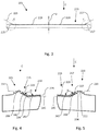
Fig. 3 : a cutter blade according to the first aspect of the present disclosure is shown; -
Fig. 4 : detail E fromFig. 3 is shown; -
Fig. 5 : detail F fromFig. 3 is shown; -
Fig. 6 : another cutter blade according the first aspect of the present disclosure is shown; -
Fig. 7 : detail I fromFig. 6 is shown; -
Fig. 8 : detail J fromFig. 6 is shown; -
Fig. 9 : detail K fromFig. 6 is shown; -
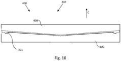
Fig. 10 : a front view of a packing container according to the second aspect of the present disclosure is shown. - The known
cutter blade 1 shown inFig. 1 has a general V-shape comprising afirst cutter leg 5 and asecond cutter leg 7. Both thefirst cutter leg 5 and thesecond cutter leg 7 are at a cutting side provided withteeth 3. A firsttooth top line 9 connects tooth tops ofteeth 3 of saidfirst cutter leg 5 and a second toottop line 11 connects tooth tops ofteeth 3 of saidsecond cutter leg 7. The first toothtop line 9 and the second toothtop line 11 enclose an angle A larger than 180 degrees. - The known
packing container 100 accommodates a roll ofpacking material 102 in acontainer housing 104. Thecontainer housing 104 comprises aholder part 106 and alid 108 that is arranged for providing in a first position of thelid 108 access to a packing receiving space of the packing container for receiving the roll of packingmaterial 102. In a closed position of thelid 108 an opening is provided between theholder part 106 and thelid 108 for allowing the packing material of the roll of packingmaterial 102 to extend outside thecontainer housing 104. The opening is at a side bound by thecutter blade 1. A piece of packingmaterial 110 may be separated from the roll of packingmaterial 102 by pulling said packing material in a cutting direction C of saidcutter blade 1 against said cutting side of saidcutter blade 1. -
Cutter blade 201 according to the first aspect of the present disclosure is symmetrical about a symmetry axis D and provided withteeth side 213 of saidcutter blade 201. Theteeth cutter blade 201 said packing material is cut. The cuttingside 213 comprises afirst portion 215, asecond portion 217 and anintermediate portion 219 between saidfirst portion 215 and saidsecond portion 217. A firsttooth top line 225 connects tooth tops ofteeth 205 of saidfirst portion 215. A secondtooth top line 227 connects tooth tops ofteeth 209 of saidsecond portion 217. An intermediatetooth top line 229 connects tooth tops ofteeth 207 of saidintermediate portion 219. - The cutting side further comprises a
third portion 221 at a side of saidfirst portion 215 opposite saidintermediate portion 219 and afourth portion 223 at a side of saidsecond portion 217 opposite saidintermediate portion 219. A thirdtooth top line 231 connects tooth tops ofteeth 203 of saidthird portion 221 and a fourthtooth top line 233 connects tooth tops ofteeth 211 of saidfourth portion 223. - A distance in said cutting direction C between said first
tooth top line 225 and afirst root line 234 that connects roots of saidteeth 205 of saidfirst portion 215 and a distance in said cutting direction C between said secondtooth top line 227 and asecond root line 236 that connects roots of saidteeth 209 of saidsecond portion 217 is larger than a distance in said cutting direction C between said intermediatetooth top line 229 and anintermediate root line 245 that connects roots of saidteeth 207 of saidfirst part 215 and saidsecond part 217. In other words, saidteeth first portion 215 and saidsecond portion 217 are larger than saidteeth 207 of saidintermediate portion 219. - The first
tooth top line 225 and said secondtooth top line 227 each enclose an obtuse angle G, H of 150 degrees with said intermediatetooth top line 229. The thirdtooth top line 231 and the fourthtooth top line 233 are parallel to the intermediatetooth top line 229. -
Cutter blade 301 differs mainly fromcutter blade 201 in that said intermediate part has a general V-shape. Elements ofcutter blade 301 that are similar to elements ofcutter blade 201 are provided with a reference number equal to the reference number of the element incutter blade 201 raised by 100.Intermediation portion 313 ofcutter blade 301 comprises afirst part 335 adjacent to saidfirst portion 315, asecond part 337 adjacent to saidsecond portion 317 and acentre part 339 between saidfirst part 335 and saidsecond part 337. The intermediatetooth top line 329 connect tooth tops ofteeth 307 of thefirst part 335 and thesecond part 337. - A centre
tooth top line 341 connects the tooth tops of teeth of saidcentre part 339. A distance in said cutting direction C between said centretooth top line 341 and acentre root line 343 of said teeth of saidcentre part 339 is larger than a distance in said cutting direction C between said intermediatetooth top line 329 and aintermediate root line 345 of said teeth of saidfirst part 335 and/or saidsecond part 337. - The packing
container 400 differs mainly from packingcontainer 100 in that said packing container comprises acutter blade 301 according to the first aspect of the present disclosure. Elements of packingcontainer 400 that are similar to elements of packingcontainer 100 are provided with a reference number equal to the reference number of the element in packingcontainer 100 raised by 300.
Claims (14)
- A cutter blade (201, 301) for a packing container (400) accommodating a roll of packing material, wherein said cutter blade (201, 301) is provided with teeth (203, 205, 207, 209, 211, 303, 305, 307, 309, 311) along a cutting side (213, 313) of said cutter blade (201, 301) for cutting said packing material in a cutting direction (C) of said cutter blade (201, 301), wherein said cutting side (213, 313) comprises a first portion (215, 315), a second portion (217, 317) and an intermediate portion (219, 319) between said first portion (215, 315) and said second portion (217, 317),
wherein a first tooth top line (225, 325) connects tooth tops of teeth (205) of said first portion (215, 315), a second tooth top line (227, 327) connects tooth tops of teeth (209) of said second portion (217, 317) and wherein an intermediate tooth top line (219, 319) connects tooth tops of teeth (207) of said intermediate portion (219, 319),
wherein said first tooth top line (225, 325) and/or said second tooth top line (227, 327) enclose an obtuse angle (G, H) between 91 and 179 degrees with said intermediate tooth top line (229, 329), characterized in that,
a distance in said cutting direction (C) between said first tooth top line (225, 325) and a first root line (234, 334) that connects roots of said teeth (205, 305) of said first portion (215, 315) and/or a distance in said cutting direction (C) between said second tooth top line (227, 327) and a second root line (236, 336) that connects roots of said teeth (209, 309) of said second portion (217, 317) is larger than a distance in said cutting direction (C) between said intermediate tooth top line (229, 329) and an intermediate root line (245, 345) that connects roots of said teeth (207, 307) of said intermediate portion (219, 319). - Cutter blade (201, 301) according to claim 1, wherein said cutting side (213, 313) comprises a third portion (221, 321) at a side of said first portion (215, 315) opposite said intermediate portion (219, 319) and/or comprises a fourth portion (223, 323) at a side of said second portion (217, 317) opposite said intermediate portion (219, 319), wherein a third tooth top line (231, 331) connects tooth tops of teeth (203) of said third portion (221, 321) and/or a fourth tooth top line (233, 333) connects tooth tops of teeth (211, 311) of said fourth portion (223, 323), wherein said third tooth top line (231, 331) and/or said fourth tooth top line (233, 333) is substantially parallel to said intermediate tooth top line (229, 329).
- Cutter blade (301) according to any one of the preceding claims, wherein said intermediate portion (319) comprises a first part (335) adjacent to said first portion (315), a second part (337) adjacent to said second portion (317) and a centre part (339) between said first part (335) and said second part (337), wherein said intermediate tooth top line (329) connects tooth tops of teeth (307) of said first part (335) and/or said second part (337).
- Cutter blade (301) according to claim 3, wherein a centre tooth top line (341) connects tooth tops of teeth (307) of said centre part (339), wherein a distance in said cutting direction (C) between said centre tooth top line (341) and a centre root line (343) that connects roots of said teeth (307) of said centre part (339) is larger than a distance in said cutting direction (C) between said intermediate tooth top line (329) and an intermediate root line (345) that connects roots of said teeth (307) of said first part (335) and/or said second part (337).
- Cutter blade (301) according to any one of the claims 3 and 4, wherein said centre part (339) is shifted positioned relative to said first part (335) and/or said second part (337) in said direction opposite to said cutting direction (C).
- Cutter blade (301) according to any one of the claims 3 to 5, wherein a pitch of said teeth (305, 309) of said first portion (315) and/or said second portion (317) is larger than a pitch of said teeth (307) of said first part (335) and/or said second part (337).
- Cutter blade (201, 301) according to any one of the preceding claims, wherein said cutter blade (201, 301) is symmetrical.
- Cutter blade (201, 301) according to any one of the preceding claims, wherein said cutter blade (201, 301) comprises a non-metallic material, preferably wherein said cutter blade is made from a non-metallic material.
- Cutter blade according to any of the claims 3 to 6, wherein said distance in said cutting direction between said first tooth top line and said first root line that connects roots of said teeth of said first portion and/or said distance in said cutting direction between said second tooth top line and said second root line that connects roots of said teeth of said second portion is larger than said distance in said cutting direction between said intermediate tooth top line and said intermediate root line that connects roots of said teeth of said first part and/or said second part.
- A packing container (400) accommodating a roll of packing material, said packing container (400) comprising a cutter blade (301) according to any one of the preceding claims, wherein said cutter blade (301) is arranged to cut said packing material for separating a piece of packing material from said roll of packing material.
- Packing container (400) according to claim 10, wherein a width of said cutter blade (301) is larger than a width of said accommodated roll of packing material, wherein said cutter blade (301) is arranged such that outer ends of said cutter blade (301) extend respectively beyond outer ends of said packing material.
- Packing container (400) according to claim 10 or 11, wherein said first portion (315) is arranged relative to said roll of packing material for cutting a first edge of said packing material and wherein said second portion (317) is arranged relative to said roll of packing material for cutting a second edge of said packing material.
- Packing container (400) according to any one of the claims 10 to 12, wherein said roll of packing material is provided with a roll receiving space and wherein said packing container comprises a holding arrangement arranged in said roll receiving space for retaining said roll of packing material inside said packing container (400) when unrolling said packing material.
- A packing container (400) according to any one of the claims 10 to 13, wherein said packing material is made of polyethylene, polypropylene, or polyvinyl chloride.
Applications Claiming Priority (1)
| Application Number | Priority Date | Filing Date | Title |
|---|---|---|---|
| NL2021278A NL2021278B1 (en) | 2018-07-10 | 2018-07-10 | Cutter blade for a packing container and a packing container |
Publications (2)
| Publication Number | Publication Date |
|---|---|
| EP3594158A1 EP3594158A1 (en) | 2020-01-15 |
| EP3594158B1 true EP3594158B1 (en) | 2021-03-24 |
Family
ID=64172546
Family Applications (1)
| Application Number | Title | Priority Date | Filing Date |
|---|---|---|---|
| EP19185193.0A Active EP3594158B1 (en) | 2018-07-10 | 2019-07-09 | Cutter blade for a packing container and a packing container |
Country Status (3)
| Country | Link |
|---|---|
| EP (1) | EP3594158B1 (en) |
| ES (1) | ES2866177T3 (en) |
| NL (1) | NL2021278B1 (en) |
Family Cites Families (4)
| Publication number | Priority date | Publication date | Assignee | Title |
|---|---|---|---|---|
| JPH05162746A (en) * | 1991-12-10 | 1993-06-29 | Kureha Chem Ind Co Ltd | Cutting member and manufacture thereof |
| JP2001018188A (en) * | 1999-07-07 | 2001-01-23 | Kao Corp | cutter |
| JP5342853B2 (en) * | 2008-11-17 | 2013-11-13 | 株式会社クレハ | Cutting blade for packaging container, packaging container and package supply device |
| WO2011052350A1 (en) * | 2009-10-26 | 2011-05-05 | 株式会社クレハ | Cutter for wrapping material, carton and wrapping material supply body comprising cutter for wrapping material |
-
2018
- 2018-07-10 NL NL2021278A patent/NL2021278B1/en active
-
2019
- 2019-07-09 ES ES19185193T patent/ES2866177T3/en active Active
- 2019-07-09 EP EP19185193.0A patent/EP3594158B1/en active Active
Non-Patent Citations (1)
| Title |
|---|
| None * |
Also Published As
| Publication number | Publication date |
|---|---|
| NL2021278B1 (en) | 2020-01-20 |
| EP3594158A1 (en) | 2020-01-15 |
| ES2866177T3 (en) | 2021-10-19 |
Similar Documents
| Publication | Publication Date | Title |
|---|---|---|
| US20220079327A1 (en) | Folding knife with pocket clip | |
| US20240199311A1 (en) | Plastic Wrap Container | |
| US20100162575A1 (en) | Gardening shears capable of increasing shearing area | |
| US3178812A (en) | Carton opening device | |
| US6923358B2 (en) | Tape dispenser with cutter shield | |
| US20150344256A1 (en) | Material dispenser | |
| GB2468665A (en) | Gardening Shears | |
| US20050198833A1 (en) | IC test fixture | |
| EP3594158A1 (en) | Cutter blade for a packing container and a packing container | |
| JP2018117863A (en) | Natto pack cutter | |
| KR101999306B1 (en) | Multi-splitting taper dispenser | |
| US20140165509A1 (en) | Folding knife with tobacco can opener | |
| CA2616636A1 (en) | Multi-function package opener | |
| EP3023339B1 (en) | Method for a packaging machine and packaging machine | |
| EP3100834B1 (en) | Guillotine arm withprotection guard | |
| JP2014231358A (en) | Package for wrap film | |
| US20040238606A1 (en) | File folder | |
| JP2018130435A (en) | cutter knife | |
| JP3169465U (en) | Cutting aids such as boxed wrap film and aluminum foil | |
| KR101551155B1 (en) | Case having a function of Cutting Wrapping Materials | |
| KR102082578B1 (en) | Wrap cutter for wrapping | |
| JP4333739B2 (en) | Roll storage case cover | |
| CN209635565U (en) | Cut box | |
| JP6497467B1 (en) | Wrapping film holder and wrapping film structure | |
| US20230249372A1 (en) | Sheet cutter |
Legal Events
| Date | Code | Title | Description |
|---|---|---|---|
| PUAI | Public reference made under article 153(3) epc to a published international application that has entered the european phase |
Free format text: ORIGINAL CODE: 0009012 |
|
| STAA | Information on the status of an ep patent application or granted ep patent |
Free format text: STATUS: THE APPLICATION HAS BEEN PUBLISHED |
|
| AK | Designated contracting states |
Kind code of ref document: A1 Designated state(s): AL AT BE BG CH CY CZ DE DK EE ES FI FR GB GR HR HU IE IS IT LI LT LU LV MC MK MT NL NO PL PT RO RS SE SI SK SM TR |
|
| AX | Request for extension of the european patent |
Extension state: BA ME |
|
| STAA | Information on the status of an ep patent application or granted ep patent |
Free format text: STATUS: REQUEST FOR EXAMINATION WAS MADE |
|
| 17P | Request for examination filed |
Effective date: 20200130 |
|
| RBV | Designated contracting states (corrected) |
Designated state(s): AL AT BE BG CH CY CZ DE DK EE ES FI FR GB GR HR HU IE IS IT LI LT LU LV MC MK MT NL NO PL PT RO RS SE SI SK SM TR |
|
| RIC1 | Information provided on ipc code assigned before grant |
Ipc: B65H 35/00 20060101AFI20201027BHEP Ipc: B65D 83/08 20060101ALI20201027BHEP |
|
| GRAP | Despatch of communication of intention to grant a patent |
Free format text: ORIGINAL CODE: EPIDOSNIGR1 |
|
| STAA | Information on the status of an ep patent application or granted ep patent |
Free format text: STATUS: GRANT OF PATENT IS INTENDED |
|
| INTG | Intention to grant announced |
Effective date: 20201217 |
|
| GRAS | Grant fee paid |
Free format text: ORIGINAL CODE: EPIDOSNIGR3 |
|
| GRAA | (expected) grant |
Free format text: ORIGINAL CODE: 0009210 |
|
| STAA | Information on the status of an ep patent application or granted ep patent |
Free format text: STATUS: THE PATENT HAS BEEN GRANTED |
|
| AK | Designated contracting states |
Kind code of ref document: B1 Designated state(s): AL AT BE BG CH CY CZ DE DK EE ES FI FR GB GR HR HU IE IS IT LI LT LU LV MC MK MT NL NO PL PT RO RS SE SI SK SM TR |
|
| REG | Reference to a national code |
Ref country code: GB Ref legal event code: FG4D |
|
| REG | Reference to a national code |
Ref country code: CH Ref legal event code: EP |
|
| REG | Reference to a national code |
Ref country code: IE Ref legal event code: FG4D |
|
| REG | Reference to a national code |
Ref country code: DE Ref legal event code: R096 Ref document number: 602019003383 Country of ref document: DE Ref country code: AT Ref legal event code: REF Ref document number: 1374302 Country of ref document: AT Kind code of ref document: T Effective date: 20210415 |
|
| REG | Reference to a national code |
Ref country code: CH Ref legal event code: NV Representative=s name: CABINET GERMAIN AND MAUREAU, CH |
|
| REG | Reference to a national code |
Ref country code: LT Ref legal event code: MG9D |
|
| PG25 | Lapsed in a contracting state [announced via postgrant information from national office to epo] |
Ref country code: NO Free format text: LAPSE BECAUSE OF FAILURE TO SUBMIT A TRANSLATION OF THE DESCRIPTION OR TO PAY THE FEE WITHIN THE PRESCRIBED TIME-LIMIT Effective date: 20210624 Ref country code: BG Free format text: LAPSE BECAUSE OF FAILURE TO SUBMIT A TRANSLATION OF THE DESCRIPTION OR TO PAY THE FEE WITHIN THE PRESCRIBED TIME-LIMIT Effective date: 20210624 Ref country code: HR Free format text: LAPSE BECAUSE OF FAILURE TO SUBMIT A TRANSLATION OF THE DESCRIPTION OR TO PAY THE FEE WITHIN THE PRESCRIBED TIME-LIMIT Effective date: 20210324 Ref country code: GR Free format text: LAPSE BECAUSE OF FAILURE TO SUBMIT A TRANSLATION OF THE DESCRIPTION OR TO PAY THE FEE WITHIN THE PRESCRIBED TIME-LIMIT Effective date: 20210625 Ref country code: FI Free format text: LAPSE BECAUSE OF FAILURE TO SUBMIT A TRANSLATION OF THE DESCRIPTION OR TO PAY THE FEE WITHIN THE PRESCRIBED TIME-LIMIT Effective date: 20210324 |
|
| PG25 | Lapsed in a contracting state [announced via postgrant information from national office to epo] |
Ref country code: SE Free format text: LAPSE BECAUSE OF FAILURE TO SUBMIT A TRANSLATION OF THE DESCRIPTION OR TO PAY THE FEE WITHIN THE PRESCRIBED TIME-LIMIT Effective date: 20210324 Ref country code: RS Free format text: LAPSE BECAUSE OF FAILURE TO SUBMIT A TRANSLATION OF THE DESCRIPTION OR TO PAY THE FEE WITHIN THE PRESCRIBED TIME-LIMIT Effective date: 20210324 Ref country code: LV Free format text: LAPSE BECAUSE OF FAILURE TO SUBMIT A TRANSLATION OF THE DESCRIPTION OR TO PAY THE FEE WITHIN THE PRESCRIBED TIME-LIMIT Effective date: 20210324 |
|
| REG | Reference to a national code |
Ref country code: NL Ref legal event code: MP Effective date: 20210324 |
|
| REG | Reference to a national code |
Ref country code: AT Ref legal event code: MK05 Ref document number: 1374302 Country of ref document: AT Kind code of ref document: T Effective date: 20210324 |
|
| PG25 | Lapsed in a contracting state [announced via postgrant information from national office to epo] |
Ref country code: NL Free format text: LAPSE BECAUSE OF FAILURE TO SUBMIT A TRANSLATION OF THE DESCRIPTION OR TO PAY THE FEE WITHIN THE PRESCRIBED TIME-LIMIT Effective date: 20210324 |
|
| REG | Reference to a national code |
Ref country code: ES Ref legal event code: FG2A Ref document number: 2866177 Country of ref document: ES Kind code of ref document: T3 Effective date: 20211019 |
|
| PG25 | Lapsed in a contracting state [announced via postgrant information from national office to epo] |
Ref country code: CZ Free format text: LAPSE BECAUSE OF FAILURE TO SUBMIT A TRANSLATION OF THE DESCRIPTION OR TO PAY THE FEE WITHIN THE PRESCRIBED TIME-LIMIT Effective date: 20210324 Ref country code: EE Free format text: LAPSE BECAUSE OF FAILURE TO SUBMIT A TRANSLATION OF THE DESCRIPTION OR TO PAY THE FEE WITHIN THE PRESCRIBED TIME-LIMIT Effective date: 20210324 Ref country code: LT Free format text: LAPSE BECAUSE OF FAILURE TO SUBMIT A TRANSLATION OF THE DESCRIPTION OR TO PAY THE FEE WITHIN THE PRESCRIBED TIME-LIMIT Effective date: 20210324 Ref country code: SM Free format text: LAPSE BECAUSE OF FAILURE TO SUBMIT A TRANSLATION OF THE DESCRIPTION OR TO PAY THE FEE WITHIN THE PRESCRIBED TIME-LIMIT Effective date: 20210324 Ref country code: AT Free format text: LAPSE BECAUSE OF FAILURE TO SUBMIT A TRANSLATION OF THE DESCRIPTION OR TO PAY THE FEE WITHIN THE PRESCRIBED TIME-LIMIT Effective date: 20210324 |
|
| PG25 | Lapsed in a contracting state [announced via postgrant information from national office to epo] |
Ref country code: PL Free format text: LAPSE BECAUSE OF FAILURE TO SUBMIT A TRANSLATION OF THE DESCRIPTION OR TO PAY THE FEE WITHIN THE PRESCRIBED TIME-LIMIT Effective date: 20210324 Ref country code: SK Free format text: LAPSE BECAUSE OF FAILURE TO SUBMIT A TRANSLATION OF THE DESCRIPTION OR TO PAY THE FEE WITHIN THE PRESCRIBED TIME-LIMIT Effective date: 20210324 Ref country code: RO Free format text: LAPSE BECAUSE OF FAILURE TO SUBMIT A TRANSLATION OF THE DESCRIPTION OR TO PAY THE FEE WITHIN THE PRESCRIBED TIME-LIMIT Effective date: 20210324 Ref country code: PT Free format text: LAPSE BECAUSE OF FAILURE TO SUBMIT A TRANSLATION OF THE DESCRIPTION OR TO PAY THE FEE WITHIN THE PRESCRIBED TIME-LIMIT Effective date: 20210726 Ref country code: IS Free format text: LAPSE BECAUSE OF FAILURE TO SUBMIT A TRANSLATION OF THE DESCRIPTION OR TO PAY THE FEE WITHIN THE PRESCRIBED TIME-LIMIT Effective date: 20210724 |
|
| REG | Reference to a national code |
Ref country code: DE Ref legal event code: R097 Ref document number: 602019003383 Country of ref document: DE |
|
| PG25 | Lapsed in a contracting state [announced via postgrant information from national office to epo] |
Ref country code: DK Free format text: LAPSE BECAUSE OF FAILURE TO SUBMIT A TRANSLATION OF THE DESCRIPTION OR TO PAY THE FEE WITHIN THE PRESCRIBED TIME-LIMIT Effective date: 20210324 Ref country code: AL Free format text: LAPSE BECAUSE OF FAILURE TO SUBMIT A TRANSLATION OF THE DESCRIPTION OR TO PAY THE FEE WITHIN THE PRESCRIBED TIME-LIMIT Effective date: 20210324 |
|
| PLBE | No opposition filed within time limit |
Free format text: ORIGINAL CODE: 0009261 |
|
| STAA | Information on the status of an ep patent application or granted ep patent |
Free format text: STATUS: NO OPPOSITION FILED WITHIN TIME LIMIT |
|
| PG25 | Lapsed in a contracting state [announced via postgrant information from national office to epo] |
Ref country code: SI Free format text: LAPSE BECAUSE OF FAILURE TO SUBMIT A TRANSLATION OF THE DESCRIPTION OR TO PAY THE FEE WITHIN THE PRESCRIBED TIME-LIMIT Effective date: 20210324 |
|
| 26N | No opposition filed |
Effective date: 20220104 |
|
| PG25 | Lapsed in a contracting state [announced via postgrant information from national office to epo] |
Ref country code: MC Free format text: LAPSE BECAUSE OF FAILURE TO SUBMIT A TRANSLATION OF THE DESCRIPTION OR TO PAY THE FEE WITHIN THE PRESCRIBED TIME-LIMIT Effective date: 20210324 |
|
| REG | Reference to a national code |
Ref country code: BE Ref legal event code: MM Effective date: 20210731 |
|
| PG25 | Lapsed in a contracting state [announced via postgrant information from national office to epo] |
Ref country code: IS Free format text: LAPSE BECAUSE OF FAILURE TO SUBMIT A TRANSLATION OF THE DESCRIPTION OR TO PAY THE FEE WITHIN THE PRESCRIBED TIME-LIMIT Effective date: 20210724 Ref country code: LU Free format text: LAPSE BECAUSE OF NON-PAYMENT OF DUE FEES Effective date: 20210709 |
|
| PG25 | Lapsed in a contracting state [announced via postgrant information from national office to epo] |
Ref country code: IE Free format text: LAPSE BECAUSE OF NON-PAYMENT OF DUE FEES Effective date: 20210709 Ref country code: BE Free format text: LAPSE BECAUSE OF NON-PAYMENT OF DUE FEES Effective date: 20210731 |
|
| PG25 | Lapsed in a contracting state [announced via postgrant information from national office to epo] |
Ref country code: IT Free format text: LAPSE BECAUSE OF FAILURE TO SUBMIT A TRANSLATION OF THE DESCRIPTION OR TO PAY THE FEE WITHIN THE PRESCRIBED TIME-LIMIT Effective date: 20210324 |
|
| PG25 | Lapsed in a contracting state [announced via postgrant information from national office to epo] |
Ref country code: CY Free format text: LAPSE BECAUSE OF FAILURE TO SUBMIT A TRANSLATION OF THE DESCRIPTION OR TO PAY THE FEE WITHIN THE PRESCRIBED TIME-LIMIT Effective date: 20210324 |
|
| P01 | Opt-out of the competence of the unified patent court (upc) registered |
Effective date: 20230527 |
|
| PG25 | Lapsed in a contracting state [announced via postgrant information from national office to epo] |
Ref country code: HU Free format text: LAPSE BECAUSE OF FAILURE TO SUBMIT A TRANSLATION OF THE DESCRIPTION OR TO PAY THE FEE WITHIN THE PRESCRIBED TIME-LIMIT; INVALID AB INITIO Effective date: 20190709 |
|
| PG25 | Lapsed in a contracting state [announced via postgrant information from national office to epo] |
Ref country code: MK Free format text: LAPSE BECAUSE OF FAILURE TO SUBMIT A TRANSLATION OF THE DESCRIPTION OR TO PAY THE FEE WITHIN THE PRESCRIBED TIME-LIMIT Effective date: 20210324 |
|
| PG25 | Lapsed in a contracting state [announced via postgrant information from national office to epo] |
Ref country code: TR Free format text: LAPSE BECAUSE OF FAILURE TO SUBMIT A TRANSLATION OF THE DESCRIPTION OR TO PAY THE FEE WITHIN THE PRESCRIBED TIME-LIMIT Effective date: 20210324 |
|
| PG25 | Lapsed in a contracting state [announced via postgrant information from national office to epo] |
Ref country code: MT Free format text: LAPSE BECAUSE OF FAILURE TO SUBMIT A TRANSLATION OF THE DESCRIPTION OR TO PAY THE FEE WITHIN THE PRESCRIBED TIME-LIMIT Effective date: 20210324 |
|
| PGFP | Annual fee paid to national office [announced via postgrant information from national office to epo] |
Ref country code: ES Payment date: 20250827 Year of fee payment: 7 |
|
| PGFP | Annual fee paid to national office [announced via postgrant information from national office to epo] |
Ref country code: DE Payment date: 20250722 Year of fee payment: 7 |
|
| PGFP | Annual fee paid to national office [announced via postgrant information from national office to epo] |
Ref country code: GB Payment date: 20250722 Year of fee payment: 7 |
|
| PGFP | Annual fee paid to national office [announced via postgrant information from national office to epo] |
Ref country code: FR Payment date: 20250725 Year of fee payment: 7 |
|
| PGFP | Annual fee paid to national office [announced via postgrant information from national office to epo] |
Ref country code: CH Payment date: 20250801 Year of fee payment: 7 |