EP3594148A1 - Packaging container - Google Patents
Packaging container Download PDFInfo
- Publication number
- EP3594148A1 EP3594148A1 EP18763458.9A EP18763458A EP3594148A1 EP 3594148 A1 EP3594148 A1 EP 3594148A1 EP 18763458 A EP18763458 A EP 18763458A EP 3594148 A1 EP3594148 A1 EP 3594148A1
- Authority
- EP
- European Patent Office
- Prior art keywords
- wrap film
- coating layer
- varnish coating
- packaging container
- film
- Prior art date
- Legal status (The legal status is an assumption and is not a legal conclusion. Google has not performed a legal analysis and makes no representation as to the accuracy of the status listed.)
- Withdrawn
Links
- 238000004806 packaging method and process Methods 0.000 title claims abstract description 55
- 239000002966 varnish Substances 0.000 claims abstract description 133
- 239000011247 coating layer Substances 0.000 claims abstract description 108
- 238000012360 testing method Methods 0.000 claims abstract description 16
- 239000004820 Pressure-sensitive adhesive Substances 0.000 claims abstract description 9
- 238000005520 cutting process Methods 0.000 claims description 82
- 229920001328 Polyvinylidene chloride Polymers 0.000 claims description 3
- 239000005033 polyvinylidene chloride Substances 0.000 claims description 3
- 230000000052 comparative effect Effects 0.000 description 33
- 239000011248 coating agent Substances 0.000 description 21
- 238000000576 coating method Methods 0.000 description 21
- 229920005989 resin Polymers 0.000 description 21
- 239000011347 resin Substances 0.000 description 21
- 238000011156 evaluation Methods 0.000 description 17
- -1 acrylic acrylates Chemical class 0.000 description 14
- 238000005096 rolling process Methods 0.000 description 12
- 239000000178 monomer Substances 0.000 description 11
- 239000000654 additive Substances 0.000 description 10
- 238000005259 measurement Methods 0.000 description 10
- 239000011342 resin composition Substances 0.000 description 9
- 238000001723 curing Methods 0.000 description 8
- 229910000831 Steel Inorganic materials 0.000 description 7
- 230000000996 additive effect Effects 0.000 description 7
- 239000000123 paper Substances 0.000 description 7
- 238000007788 roughening Methods 0.000 description 7
- 239000010959 steel Substances 0.000 description 7
- 239000004793 Polystyrene Substances 0.000 description 6
- 229920002223 polystyrene Polymers 0.000 description 6
- NIXOWILDQLNWCW-UHFFFAOYSA-M acrylate group Chemical group C(C=C)(=O)[O-] NIXOWILDQLNWCW-UHFFFAOYSA-M 0.000 description 5
- 238000011282 treatment Methods 0.000 description 5
- 239000005977 Ethylene Substances 0.000 description 4
- BXKDSDJJOVIHMX-UHFFFAOYSA-N edrophonium chloride Chemical compound [Cl-].CC[N+](C)(C)C1=CC=CC(O)=C1 BXKDSDJJOVIHMX-UHFFFAOYSA-N 0.000 description 4
- 239000000463 material Substances 0.000 description 4
- 238000000034 method Methods 0.000 description 4
- 238000007719 peel strength test Methods 0.000 description 4
- QQONPFPTGQHPMA-UHFFFAOYSA-N propylene Natural products CC=C QQONPFPTGQHPMA-UHFFFAOYSA-N 0.000 description 4
- CERQOIWHTDAKMF-UHFFFAOYSA-M Methacrylate Chemical compound CC(=C)C([O-])=O CERQOIWHTDAKMF-UHFFFAOYSA-M 0.000 description 3
- TZCXTZWJZNENPQ-UHFFFAOYSA-L barium sulfate Chemical compound [Ba+2].[O-]S([O-])(=O)=O TZCXTZWJZNENPQ-UHFFFAOYSA-L 0.000 description 3
- 238000004519 manufacturing process Methods 0.000 description 3
- QSHDDOUJBYECFT-UHFFFAOYSA-N mercury Chemical compound [Hg] QSHDDOUJBYECFT-UHFFFAOYSA-N 0.000 description 3
- 229910052753 mercury Inorganic materials 0.000 description 3
- 239000012766 organic filler Substances 0.000 description 3
- 239000000243 solution Substances 0.000 description 3
- 238000009281 ultraviolet germicidal irradiation Methods 0.000 description 3
- PJAKWOZHTFWTNF-UHFFFAOYSA-N (2-nonylphenyl) prop-2-enoate Chemical class CCCCCCCCCC1=CC=CC=C1OC(=O)C=C PJAKWOZHTFWTNF-UHFFFAOYSA-N 0.000 description 2
- IHCCLXNEEPMSIO-UHFFFAOYSA-N 2-[4-[2-(2,3-dihydro-1H-inden-2-ylamino)pyrimidin-5-yl]piperidin-1-yl]-1-(2,4,6,7-tetrahydrotriazolo[4,5-c]pyridin-5-yl)ethanone Chemical compound C1C(CC2=CC=CC=C12)NC1=NC=C(C=N1)C1CCN(CC1)CC(=O)N1CC2=C(CC1)NN=N2 IHCCLXNEEPMSIO-UHFFFAOYSA-N 0.000 description 2
- RZVINYQDSSQUKO-UHFFFAOYSA-N 2-phenoxyethyl prop-2-enoate Chemical compound C=CC(=O)OCCOC1=CC=CC=C1 RZVINYQDSSQUKO-UHFFFAOYSA-N 0.000 description 2
- VTYYLEPIZMXCLO-UHFFFAOYSA-L Calcium carbonate Chemical compound [Ca+2].[O-]C([O-])=O VTYYLEPIZMXCLO-UHFFFAOYSA-L 0.000 description 2
- 150000001252 acrylic acid derivatives Chemical class 0.000 description 2
- 239000000853 adhesive Substances 0.000 description 2
- 230000001070 adhesive effect Effects 0.000 description 2
- 230000000694 effects Effects 0.000 description 2
- 239000011256 inorganic filler Substances 0.000 description 2
- 229910003475 inorganic filler Inorganic materials 0.000 description 2
- YDKNBNOOCSNPNS-UHFFFAOYSA-N methyl 1,3-benzoxazole-2-carboxylate Chemical compound C1=CC=C2OC(C(=O)OC)=NC2=C1 YDKNBNOOCSNPNS-UHFFFAOYSA-N 0.000 description 2
- 230000000704 physical effect Effects 0.000 description 2
- 229920000747 poly(lactic acid) Polymers 0.000 description 2
- 239000004645 polyester resin Substances 0.000 description 2
- 229920001225 polyester resin Polymers 0.000 description 2
- 239000004626 polylactic acid Substances 0.000 description 2
- 238000006116 polymerization reaction Methods 0.000 description 2
- 238000010526 radical polymerization reaction Methods 0.000 description 2
- 230000001953 sensory effect Effects 0.000 description 2
- 239000002904 solvent Substances 0.000 description 2
- 238000003860 storage Methods 0.000 description 2
- MXFQRSUWYYSPOC-UHFFFAOYSA-N (2,2-dimethyl-3-prop-2-enoyloxypropyl) prop-2-enoate Chemical class C=CC(=O)OCC(C)(C)COC(=O)C=C MXFQRSUWYYSPOC-UHFFFAOYSA-N 0.000 description 1
- PRBBFHSSJFGXJS-UHFFFAOYSA-N (2,2-dimethyl-3-prop-2-enoyloxypropyl) prop-2-enoate;3-hydroxy-2,2-dimethylpropanoic acid Chemical compound OCC(C)(C)C(O)=O.C=CC(=O)OCC(C)(C)COC(=O)C=C PRBBFHSSJFGXJS-UHFFFAOYSA-N 0.000 description 1
- BJBGUIFMARZSCE-UHFFFAOYSA-N (2-ethyl-2-methyl-1-prop-2-enoyloxyhexyl) prop-2-enoate Chemical compound CCCCC(C)(CC)C(OC(=O)C=C)OC(=O)C=C BJBGUIFMARZSCE-UHFFFAOYSA-N 0.000 description 1
- PSGCQDPCAWOCSH-UHFFFAOYSA-N (4,7,7-trimethyl-3-bicyclo[2.2.1]heptanyl) prop-2-enoate Chemical compound C1CC2(C)C(OC(=O)C=C)CC1C2(C)C PSGCQDPCAWOCSH-UHFFFAOYSA-N 0.000 description 1
- MYWOJODOMFBVCB-UHFFFAOYSA-N 1,2,6-trimethylphenanthrene Chemical compound CC1=CC=C2C3=CC(C)=CC=C3C=CC2=C1C MYWOJODOMFBVCB-UHFFFAOYSA-N 0.000 description 1
- OHVLMTFVQDZYHP-UHFFFAOYSA-N 1-(2,4,6,7-tetrahydrotriazolo[4,5-c]pyridin-5-yl)-2-[4-[2-[[3-(trifluoromethoxy)phenyl]methylamino]pyrimidin-5-yl]piperazin-1-yl]ethanone Chemical compound N1N=NC=2CN(CCC=21)C(CN1CCN(CC1)C=1C=NC(=NC=1)NCC1=CC(=CC=C1)OC(F)(F)F)=O OHVLMTFVQDZYHP-UHFFFAOYSA-N 0.000 description 1
- SYENVBKSVVOOPS-UHFFFAOYSA-N 2,2-bis(hydroxymethyl)butyl prop-2-enoate Chemical compound CCC(CO)(CO)COC(=O)C=C SYENVBKSVVOOPS-UHFFFAOYSA-N 0.000 description 1
- LDXJRKWFNNFDSA-UHFFFAOYSA-N 2-(2,4,6,7-tetrahydrotriazolo[4,5-c]pyridin-5-yl)-1-[4-[2-[[3-(trifluoromethoxy)phenyl]methylamino]pyrimidin-5-yl]piperazin-1-yl]ethanone Chemical compound C1CN(CC2=NNN=C21)CC(=O)N3CCN(CC3)C4=CN=C(N=C4)NCC5=CC(=CC=C5)OC(F)(F)F LDXJRKWFNNFDSA-UHFFFAOYSA-N 0.000 description 1
- FTALTLPZDVFJSS-UHFFFAOYSA-N 2-(2-ethoxyethoxy)ethyl prop-2-enoate Chemical compound CCOCCOCCOC(=O)C=C FTALTLPZDVFJSS-UHFFFAOYSA-N 0.000 description 1
- YATYDCQGPUOZGZ-UHFFFAOYSA-N 2-(2-hydroxypropoxy)propan-1-ol;prop-2-enoic acid Chemical compound OC(=O)C=C.CC(O)COC(C)CO YATYDCQGPUOZGZ-UHFFFAOYSA-N 0.000 description 1
- OEPOKWHJYJXUGD-UHFFFAOYSA-N 2-(3-phenylmethoxyphenyl)-1,3-thiazole-4-carbaldehyde Chemical compound O=CC1=CSC(C=2C=C(OCC=3C=CC=CC=3)C=CC=2)=N1 OEPOKWHJYJXUGD-UHFFFAOYSA-N 0.000 description 1
- YIJYFLXQHDOQGW-UHFFFAOYSA-N 2-[2,4,6-trioxo-3,5-bis(2-prop-2-enoyloxyethyl)-1,3,5-triazinan-1-yl]ethyl prop-2-enoate Chemical compound C=CC(=O)OCCN1C(=O)N(CCOC(=O)C=C)C(=O)N(CCOC(=O)C=C)C1=O YIJYFLXQHDOQGW-UHFFFAOYSA-N 0.000 description 1
- COORVRSSRBIIFJ-UHFFFAOYSA-N 2-[2-(2-hydroxyethoxy)ethoxy]-1-methoxyethanol;prop-2-enoic acid Chemical compound OC(=O)C=C.COC(O)COCCOCCO COORVRSSRBIIFJ-UHFFFAOYSA-N 0.000 description 1
- JTEWHEJTRPHSAA-UHFFFAOYSA-N 2-ethylhexyl prop-2-enoate oxirane Chemical compound C(C=C)(=O)OCC(CCCC)CC.C1CO1 JTEWHEJTRPHSAA-UHFFFAOYSA-N 0.000 description 1
- FQMIAEWUVYWVNB-UHFFFAOYSA-N 3-prop-2-enoyloxybutyl prop-2-enoate Chemical compound C=CC(=O)OC(C)CCOC(=O)C=C FQMIAEWUVYWVNB-UHFFFAOYSA-N 0.000 description 1
- NDWUBGAGUCISDV-UHFFFAOYSA-N 4-hydroxybutyl prop-2-enoate Chemical compound OCCCCOC(=O)C=C NDWUBGAGUCISDV-UHFFFAOYSA-N 0.000 description 1
- JHWGFJBTMHEZME-UHFFFAOYSA-N 4-prop-2-enoyloxybutyl prop-2-enoate Chemical compound C=CC(=O)OCCCCOC(=O)C=C JHWGFJBTMHEZME-UHFFFAOYSA-N 0.000 description 1
- DFGKGUXTPFWHIX-UHFFFAOYSA-N 6-[2-[4-[2-(2,3-dihydro-1H-inden-2-ylamino)pyrimidin-5-yl]piperazin-1-yl]acetyl]-3H-1,3-benzoxazol-2-one Chemical compound C1C(CC2=CC=CC=C12)NC1=NC=C(C=N1)N1CCN(CC1)CC(=O)C1=CC2=C(NC(O2)=O)C=C1 DFGKGUXTPFWHIX-UHFFFAOYSA-N 0.000 description 1
- JTHZUSWLNCPZLX-UHFFFAOYSA-N 6-fluoro-3-methyl-2h-indazole Chemical compound FC1=CC=C2C(C)=NNC2=C1 JTHZUSWLNCPZLX-UHFFFAOYSA-N 0.000 description 1
- FIHBHSQYSYVZQE-UHFFFAOYSA-N 6-prop-2-enoyloxyhexyl prop-2-enoate Chemical compound C=CC(=O)OCCCCCCOC(=O)C=C FIHBHSQYSYVZQE-UHFFFAOYSA-N 0.000 description 1
- PGDIJTMOHORACQ-UHFFFAOYSA-N 9-prop-2-enoyloxynonyl prop-2-enoate Chemical compound C=CC(=O)OCCCCCCCCCOC(=O)C=C PGDIJTMOHORACQ-UHFFFAOYSA-N 0.000 description 1
- 239000004925 Acrylic resin Substances 0.000 description 1
- 229920000178 Acrylic resin Polymers 0.000 description 1
- OKTJSMMVPCPJKN-UHFFFAOYSA-N Carbon Chemical compound [C] OKTJSMMVPCPJKN-UHFFFAOYSA-N 0.000 description 1
- 239000004593 Epoxy Substances 0.000 description 1
- 239000004640 Melamine resin Substances 0.000 description 1
- 229920000877 Melamine resin Polymers 0.000 description 1
- NIPNSKYNPDTRPC-UHFFFAOYSA-N N-[2-oxo-2-(2,4,6,7-tetrahydrotriazolo[4,5-c]pyridin-5-yl)ethyl]-2-[[3-(trifluoromethoxy)phenyl]methylamino]pyrimidine-5-carboxamide Chemical compound O=C(CNC(=O)C=1C=NC(=NC=1)NCC1=CC(=CC=C1)OC(F)(F)F)N1CC2=C(CC1)NN=N2 NIPNSKYNPDTRPC-UHFFFAOYSA-N 0.000 description 1
- 239000004698 Polyethylene Substances 0.000 description 1
- 239000002202 Polyethylene glycol Substances 0.000 description 1
- 239000004743 Polypropylene Substances 0.000 description 1
- 239000004809 Teflon Substances 0.000 description 1
- 229920006362 Teflon® Polymers 0.000 description 1
- 239000007983 Tris buffer Substances 0.000 description 1
- 229920001807 Urea-formaldehyde Polymers 0.000 description 1
- HVVWZTWDBSEWIH-UHFFFAOYSA-N [2-(hydroxymethyl)-3-prop-2-enoyloxy-2-(prop-2-enoyloxymethyl)propyl] prop-2-enoate Chemical compound C=CC(=O)OCC(CO)(COC(=O)C=C)COC(=O)C=C HVVWZTWDBSEWIH-UHFFFAOYSA-N 0.000 description 1
- XRMBQHTWUBGQDN-UHFFFAOYSA-N [2-[2,2-bis(prop-2-enoyloxymethyl)butoxymethyl]-2-(prop-2-enoyloxymethyl)butyl] prop-2-enoate Chemical compound C=CC(=O)OCC(COC(=O)C=C)(CC)COCC(CC)(COC(=O)C=C)COC(=O)C=C XRMBQHTWUBGQDN-UHFFFAOYSA-N 0.000 description 1
- KNSXNCFKSZZHEA-UHFFFAOYSA-N [3-prop-2-enoyloxy-2,2-bis(prop-2-enoyloxymethyl)propyl] prop-2-enoate Chemical class C=CC(=O)OCC(COC(=O)C=C)(COC(=O)C=C)COC(=O)C=C KNSXNCFKSZZHEA-UHFFFAOYSA-N 0.000 description 1
- MPIAGWXWVAHQBB-UHFFFAOYSA-N [3-prop-2-enoyloxy-2-[[3-prop-2-enoyloxy-2,2-bis(prop-2-enoyloxymethyl)propoxy]methyl]-2-(prop-2-enoyloxymethyl)propyl] prop-2-enoate Chemical compound C=CC(=O)OCC(COC(=O)C=C)(COC(=O)C=C)COCC(COC(=O)C=C)(COC(=O)C=C)COC(=O)C=C MPIAGWXWVAHQBB-UHFFFAOYSA-N 0.000 description 1
- FHLPGTXWCFQMIU-UHFFFAOYSA-N [4-[2-(4-prop-2-enoyloxyphenyl)propan-2-yl]phenyl] prop-2-enoate Chemical compound C=1C=C(OC(=O)C=C)C=CC=1C(C)(C)C1=CC=C(OC(=O)C=C)C=C1 FHLPGTXWCFQMIU-UHFFFAOYSA-N 0.000 description 1
- RJDOZRNNYVAULJ-UHFFFAOYSA-L [O--].[O--].[O--].[O--].[O--].[O--].[O--].[O--].[O--].[O--].[F-].[F-].[Mg++].[Mg++].[Mg++].[Al+3].[Si+4].[Si+4].[Si+4].[K+] Chemical compound [O--].[O--].[O--].[O--].[O--].[O--].[O--].[O--].[O--].[O--].[F-].[F-].[Mg++].[Mg++].[Mg++].[Al+3].[Si+4].[Si+4].[Si+4].[K+] RJDOZRNNYVAULJ-UHFFFAOYSA-L 0.000 description 1
- 150000008062 acetophenones Chemical class 0.000 description 1
- WNROFYMDJYEPJX-UHFFFAOYSA-K aluminium hydroxide Chemical compound [OH-].[OH-].[OH-].[Al+3] WNROFYMDJYEPJX-UHFFFAOYSA-K 0.000 description 1
- PNEYBMLMFCGWSK-UHFFFAOYSA-N aluminium oxide Inorganic materials [O-2].[O-2].[O-2].[Al+3].[Al+3] PNEYBMLMFCGWSK-UHFFFAOYSA-N 0.000 description 1
- 150000001412 amines Chemical class 0.000 description 1
- 239000002518 antifoaming agent Substances 0.000 description 1
- JRPBQTZRNDNNOP-UHFFFAOYSA-N barium titanate Chemical compound [Ba+2].[Ba+2].[O-][Ti]([O-])([O-])[O-] JRPBQTZRNDNNOP-UHFFFAOYSA-N 0.000 description 1
- 229910002113 barium titanate Inorganic materials 0.000 description 1
- AYJRCSIUFZENHW-DEQYMQKBSA-L barium(2+);oxomethanediolate Chemical compound [Ba+2].[O-][14C]([O-])=O AYJRCSIUFZENHW-DEQYMQKBSA-L 0.000 description 1
- 239000012965 benzophenone Substances 0.000 description 1
- 150000008366 benzophenones Chemical class 0.000 description 1
- 230000015572 biosynthetic process Effects 0.000 description 1
- 229910000019 calcium carbonate Inorganic materials 0.000 description 1
- 229910052799 carbon Inorganic materials 0.000 description 1
- 238000006243 chemical reaction Methods 0.000 description 1
- 239000003795 chemical substances by application Substances 0.000 description 1
- 239000003086 colorant Substances 0.000 description 1
- 150000001875 compounds Chemical class 0.000 description 1
- 238000004132 cross linking Methods 0.000 description 1
- 125000004386 diacrylate group Chemical group 0.000 description 1
- 239000012954 diazonium Substances 0.000 description 1
- 238000007865 diluting Methods 0.000 description 1
- 238000001035 drying Methods 0.000 description 1
- 238000010894 electron beam technology Methods 0.000 description 1
- 239000003822 epoxy resin Substances 0.000 description 1
- 150000002148 esters Chemical class 0.000 description 1
- UHESRSKEBRADOO-UHFFFAOYSA-N ethyl carbamate;prop-2-enoic acid Chemical class OC(=O)C=C.CCOC(N)=O UHESRSKEBRADOO-UHFFFAOYSA-N 0.000 description 1
- 239000005038 ethylene vinyl acetate Substances 0.000 description 1
- 238000010438 heat treatment Methods 0.000 description 1
- 239000003999 initiator Substances 0.000 description 1
- ZFSLODLOARCGLH-UHFFFAOYSA-N isocyanuric acid Chemical compound OC1=NC(O)=NC(O)=N1 ZFSLODLOARCGLH-UHFFFAOYSA-N 0.000 description 1
- PBOSTUDLECTMNL-UHFFFAOYSA-N lauryl acrylate Chemical compound CCCCCCCCCCCCOC(=O)C=C PBOSTUDLECTMNL-UHFFFAOYSA-N 0.000 description 1
- 239000010410 layer Substances 0.000 description 1
- 239000002932 luster Substances 0.000 description 1
- ZLNQQNXFFQJAID-UHFFFAOYSA-L magnesium carbonate Chemical compound [Mg+2].[O-]C([O-])=O ZLNQQNXFFQJAID-UHFFFAOYSA-L 0.000 description 1
- 239000001095 magnesium carbonate Substances 0.000 description 1
- 229910000021 magnesium carbonate Inorganic materials 0.000 description 1
- 229910001507 metal halide Inorganic materials 0.000 description 1
- 150000005309 metal halides Chemical class 0.000 description 1
- 239000010445 mica Substances 0.000 description 1
- 229910052618 mica group Inorganic materials 0.000 description 1
- 238000012986 modification Methods 0.000 description 1
- 230000004048 modification Effects 0.000 description 1
- 239000004745 nonwoven fabric Substances 0.000 description 1
- RZFODFPMOHAYIR-UHFFFAOYSA-N oxepan-2-one;prop-2-enoic acid Chemical compound OC(=O)C=C.O=C1CCCCCO1 RZFODFPMOHAYIR-UHFFFAOYSA-N 0.000 description 1
- 239000011087 paperboard Substances 0.000 description 1
- 150000003003 phosphines Chemical class 0.000 description 1
- 229920003023 plastic Polymers 0.000 description 1
- 239000004033 plastic Substances 0.000 description 1
- 229920001200 poly(ethylene-vinyl acetate) Polymers 0.000 description 1
- 229920006122 polyamide resin Polymers 0.000 description 1
- 229920000647 polyepoxide Polymers 0.000 description 1
- 229920000728 polyester Polymers 0.000 description 1
- 229920006267 polyester film Polymers 0.000 description 1
- 229920000573 polyethylene Polymers 0.000 description 1
- 229920001223 polyethylene glycol Polymers 0.000 description 1
- 229920013716 polyethylene resin Polymers 0.000 description 1
- 229920001721 polyimide Polymers 0.000 description 1
- 239000009719 polyimide resin Substances 0.000 description 1
- 229920000306 polymethylpentene Polymers 0.000 description 1
- 239000011116 polymethylpentene Substances 0.000 description 1
- 229920001155 polypropylene Polymers 0.000 description 1
- 229920005650 polypropylene glycol diacrylate Polymers 0.000 description 1
- 229920001296 polysiloxane Polymers 0.000 description 1
- 239000004800 polyvinyl chloride Substances 0.000 description 1
- 229920000915 polyvinyl chloride Polymers 0.000 description 1
- 238000002360 preparation method Methods 0.000 description 1
- 238000003672 processing method Methods 0.000 description 1
- 239000002994 raw material Substances 0.000 description 1
- 238000010008 shearing Methods 0.000 description 1
- 239000007787 solid Substances 0.000 description 1
- 235000012424 soybean oil Nutrition 0.000 description 1
- 239000003549 soybean oil Substances 0.000 description 1
- 239000000126 substance Substances 0.000 description 1
- 239000002344 surface layer Substances 0.000 description 1
- 230000003746 surface roughness Effects 0.000 description 1
- 239000000454 talc Substances 0.000 description 1
- 229910052623 talc Inorganic materials 0.000 description 1
- MUTNCGKQJGXKEM-UHFFFAOYSA-N tamibarotene Chemical compound C=1C=C2C(C)(C)CCC(C)(C)C2=CC=1NC(=O)C1=CC=C(C(O)=O)C=C1 MUTNCGKQJGXKEM-UHFFFAOYSA-N 0.000 description 1
- 238000004154 testing of material Methods 0.000 description 1
- XOALFFJGWSCQEO-UHFFFAOYSA-N tridecyl prop-2-enoate Chemical compound CCCCCCCCCCCCCOC(=O)C=C XOALFFJGWSCQEO-UHFFFAOYSA-N 0.000 description 1
- 235000015112 vegetable and seed oil Nutrition 0.000 description 1
- 239000008158 vegetable oil Substances 0.000 description 1
- 238000004804 winding Methods 0.000 description 1
- 229910052724 xenon Inorganic materials 0.000 description 1
- FHNFHKCVQCLJFQ-UHFFFAOYSA-N xenon atom Chemical compound [Xe] FHNFHKCVQCLJFQ-UHFFFAOYSA-N 0.000 description 1
Images
Classifications
-
- B—PERFORMING OPERATIONS; TRANSPORTING
- B65—CONVEYING; PACKING; STORING; HANDLING THIN OR FILAMENTARY MATERIAL
- B65D—CONTAINERS FOR STORAGE OR TRANSPORT OF ARTICLES OR MATERIALS, e.g. BAGS, BARRELS, BOTTLES, BOXES, CANS, CARTONS, CRATES, DRUMS, JARS, TANKS, HOPPERS, FORWARDING CONTAINERS; ACCESSORIES, CLOSURES, OR FITTINGS THEREFOR; PACKAGING ELEMENTS; PACKAGES
- B65D83/00—Containers or packages with special means for dispensing contents
- B65D83/08—Containers or packages with special means for dispensing contents for dispensing thin flat articles in succession
- B65D83/0847—Containers or packages with special means for dispensing contents for dispensing thin flat articles in succession through an aperture at the junction of two walls
- B65D83/0852—Containers or packages with special means for dispensing contents for dispensing thin flat articles in succession through an aperture at the junction of two walls with means for assisting dispensing
- B65D83/0882—Containers or packages with special means for dispensing contents for dispensing thin flat articles in succession through an aperture at the junction of two walls with means for assisting dispensing and for cutting interconnected articles
-
- B—PERFORMING OPERATIONS; TRANSPORTING
- B26—HAND CUTTING TOOLS; CUTTING; SEVERING
- B26D—CUTTING; DETAILS COMMON TO MACHINES FOR PERFORATING, PUNCHING, CUTTING-OUT, STAMPING-OUT OR SEVERING
- B26D1/00—Cutting through work characterised by the nature or movement of the cutting member or particular materials not otherwise provided for; Apparatus or machines therefor; Cutting members therefor
- B26D1/01—Cutting through work characterised by the nature or movement of the cutting member or particular materials not otherwise provided for; Apparatus or machines therefor; Cutting members therefor involving a cutting member which does not travel with the work
- B26D1/015—Cutting through work characterised by the nature or movement of the cutting member or particular materials not otherwise provided for; Apparatus or machines therefor; Cutting members therefor involving a cutting member which does not travel with the work for thin material, e.g. for sheets, strips or the like
-
- B—PERFORMING OPERATIONS; TRANSPORTING
- B65—CONVEYING; PACKING; STORING; HANDLING THIN OR FILAMENTARY MATERIAL
- B65H—HANDLING THIN OR FILAMENTARY MATERIAL, e.g. SHEETS, WEBS, CABLES
- B65H35/00—Delivering articles from cutting or line-perforating machines; Article or web delivery apparatus incorporating cutting or line-perforating devices, e.g. adhesive tape dispensers
- B65H35/0006—Article or web delivery apparatus incorporating cutting or line-perforating devices
- B65H35/002—Hand-held or table apparatus
-
- B—PERFORMING OPERATIONS; TRANSPORTING
- B65—CONVEYING; PACKING; STORING; HANDLING THIN OR FILAMENTARY MATERIAL
- B65H—HANDLING THIN OR FILAMENTARY MATERIAL, e.g. SHEETS, WEBS, CABLES
- B65H35/00—Delivering articles from cutting or line-perforating machines; Article or web delivery apparatus incorporating cutting or line-perforating devices, e.g. adhesive tape dispensers
- B65H35/0006—Article or web delivery apparatus incorporating cutting or line-perforating devices
- B65H35/0073—Details
- B65H35/008—Arrangements or adaptations of cutting devices
-
- B—PERFORMING OPERATIONS; TRANSPORTING
- B26—HAND CUTTING TOOLS; CUTTING; SEVERING
- B26D—CUTTING; DETAILS COMMON TO MACHINES FOR PERFORATING, PUNCHING, CUTTING-OUT, STAMPING-OUT OR SEVERING
- B26D1/00—Cutting through work characterised by the nature or movement of the cutting member or particular materials not otherwise provided for; Apparatus or machines therefor; Cutting members therefor
- B26D1/0006—Cutting members therefor
- B26D2001/006—Cutting members therefor the cutting blade having a special shape, e.g. a special outline, serrations
-
- B—PERFORMING OPERATIONS; TRANSPORTING
- B65—CONVEYING; PACKING; STORING; HANDLING THIN OR FILAMENTARY MATERIAL
- B65H—HANDLING THIN OR FILAMENTARY MATERIAL, e.g. SHEETS, WEBS, CABLES
- B65H2402/00—Constructional details of the handling apparatus
- B65H2402/40—Details of frames, housings or mountings of the whole handling apparatus
- B65H2402/44—Housings
- B65H2402/443—Housings with openings for delivering material, e.g. for dispensing webs
-
- B—PERFORMING OPERATIONS; TRANSPORTING
- B65—CONVEYING; PACKING; STORING; HANDLING THIN OR FILAMENTARY MATERIAL
- B65H—HANDLING THIN OR FILAMENTARY MATERIAL, e.g. SHEETS, WEBS, CABLES
- B65H2701/00—Handled material; Storage means
- B65H2701/10—Handled articles or webs
- B65H2701/17—Nature of material
- B65H2701/175—Plastic
- B65H2701/1752—Polymer film
-
- B—PERFORMING OPERATIONS; TRANSPORTING
- B65—CONVEYING; PACKING; STORING; HANDLING THIN OR FILAMENTARY MATERIAL
- B65H—HANDLING THIN OR FILAMENTARY MATERIAL, e.g. SHEETS, WEBS, CABLES
- B65H2701/00—Handled material; Storage means
- B65H2701/10—Handled articles or webs
- B65H2701/19—Specific article or web
- B65H2701/1944—Wrapping or packing material
Definitions
- the present invention relates to a packaging container. More particularly, the present invention relates to a packaging container that houses a wrap film.
- a packaging container in which varnish is applied to a front panel of a packaging container body is known as a packaging container that is configured to house a wrap roll.
- the application of varnish to the front panel of the packaging container body makes it possible for the pulled-out wrap film to sufficiently adhere and lock to the front panel, making it easier to cut the wrap film. Furthermore, after cutting, it is possible to prevent the wrap film from rolling back to the wrap roll side, and the wrap film is easily pulled out when used for next time.
- Patent Document 1 discloses a packaging container containing a varnish coating layer that temporarily adheres to a wrap film, wherein, a strength upon sliding and a T-peel strength of the varnish coating layer with respect to the wrap film are defined.
- Patent Document 1 JP 2014-005079 A
- an object of the present invention is to provide a packaging container in which the ease of pinching a wrap film therefrom is not liable to change over time and which can maintain the ease of pinching the wrap film.
- the packaging container according to the present invention is a packaging container provided with a container body that houses a wrap film roll therein and that has an open upper side and provided with a lid body connected to a rear panel of the container body, a varnish coating layer being disposed on a front panel of the container body, and the varnish coating layer satisfying Requirement 1 below.
- T-peel strength T i measured immediately after adhesion of the wrap film
- T-peel strength T 3d measured three days after the adhesion of the wrap film satisfy ⁇ (T 3d - T i )/T i ⁇ ⁇ 100 ⁇ 50.
- the present invention can provide a packaging container in which the ease of pinching a wrap film therefrom is not liable to change over time and which can maintain the ease of pinching the wrap film.
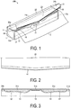
- FIG. 1 is a perspective view illustrating a packaging container according to the present embodiment.
- a packaging container 100 is a box container configured to store a wrap roll (wrap film roll) 1 in which a wrap film 2 is wound in a roll shape in a manner that the axial direction of the wrap roll 1 is in parallel with the longitudinal direction of the packaging container 100.
- the packaging container 100 is provided with a container body 11 and a lid body 21. Furthermore, although the details are described below, the container body 11 is provided with a flap 51 and varnish coating layers 31, and the lid body 21 is provided with a cutting blade 41.
- the packaging container 100 of the present embodiment is a carton formed from paperboard, but the material and the shape are not limited thereto. For example, plastic besides paper may be used. The shape may also be a cylindrical shape besides a box shape.
- the container body 11 is a box-shaped container having an open upper side, and its shape is cuboid in which a bottom face is rectangular.
- the container body 11 is formed from a bottom panel 12, a front panel 13, a rear panel 14, a side panel 15a, and a side panel 15b.
- the front panel 13 and the rear panel 14 are provided standing on the long sides of the bottom panel 12.
- the side panels 15a, 15b are provided standing on the short sides of the bottom panel 12.
- the front panel 13 is connected to each of the side panels 15a, 15b, and the rear panel 14 is also connected to each of the side panels 15a, 15b. By this configuration, the front panel 13, the side panel 15a, the rear panel 14, and the side panel 15b are continuous.
- the container body 11 has an open upper side, forming an opening part 16.
- the lid body 21 is a lid that covers the opening part 16 on the upper face of the container body 11 in a manner that the lid body 21 can be opened and closed, and the lid body 21 is connected to the rear panel 14 of the container body 11.
- the lid body 21 is formed from a lid top panel 22, a lid front panel 23, and lid side panels 24a, 24b.
- One of the long sides of the lid top panel 22 is connected to an upper side 14a of the rear panel 14 of the container body 11.
- the lid front panel 23 is connected to the other long side of the lid top panel 22.
- the lid side panels 24a, 24b are each connected to each of the short sides of the lid top panel 22.
- the lid front panel 23 covers a part of the front panel 13 of the container body 11 when the lid body 21 is closed. Therefore, when the wrap film 2 is pulled out and the lid body 21 is closed, the wrap film 2 is sandwiched between the lid front panel 23 and the front panel 13 of the container body 11 at the portion where the lid front panel 23 covers the front panel 13 of the container body 11.
- the lid side panels 24a and 24b respectively cover some parts of the side panels 15a and 15b.
- the varnish coating layer 31 is provided on the front panel 13 of the container body 11.
- the varnish coating layer 31 is provided for the pulled-out wrap film 2 to adhere and lock to the front panel 13.
- the wrap film 2 adheres to the varnish coating layer 31. Therefore, when the lid body 21 is closed and the wrap film 2 is cut, the wrap film 2 can be surely locked and can be easily cut. Furthermore, after the wrap film 2 is cut, it is possible to prevent the pulled-out wrap film 2 from rolling back to the wrap roll 1.
- the varnish coating layer 31 is provided so as to be in contact with the wrap film 2 by allowing the wrap film 2 to be sandwiched between the lid front panel 23 and the front panel 13 when the lid body 21 is closed.
- FIG. 3 illustrates an embodiment of a pattern of the varnish coating layer 31.
- the varnish coating layer 31 is formed from a central varnish coating layer 31a provided in the center of the upper side of the front panel 13 (on the opening part side of the container body), end varnish coating layers 31b provided at the ends in the longitudinal direction on the upper side of the front panel 13, and flap varnish coating layers 31c provided on the flaps 51 described below.
- the varnish coating layer 31 has a T-peel strength that satisfies Requirement 1 below for the wrap film 2.
- T-peel strength T i measured immediately after adhesion of the wrap film
- T-peel strength T 3d measured three days after the adhesion of the wrap film satisfy ⁇ (T 3d - T i )/T i ⁇ ⁇ 100 ⁇ 50.
- the above formula represents that the increased percentage in the T-peel strength measured three days after the adhesion of the wrap film relative to the T-peel strength measured immediately after the adhesion of the wrap film is 50% or less.
- the T-peel strength of the sample piece and the wrap film means a peel strength when the wrap film 2 adhering to the varnish coating layer 31 is pulled vertically relative to the varnish coating layer 31. Specifically, it corresponds to the 90° peel adhesion in JIS Z-0237:2009 described above. Note that the detailed test conditions are as described in Examples below.
- the varnish coating layer 31 of the present embodiment has a T-peel strength that satisfies Requirement 2 below for the wrap film 2.
- the T-peel strength T i immediately after adhesion of the wrap film is 4.0 ⁇ 10 -2 N/25 mm or less.
- Satisfying Requirement 2 described above for the T-peel strength T i can prevent the adhesion of the pulled-out wrap film 2 to the varnish coating layer 31 from being too strong even immediately after the wrap film 2 adhered to the varnish coating layer 31 or three days after the adhesion.
- the T-peel strength T i immediately after adhesion of the wrap film is 4.0 ⁇ 10 -2 N/25 mm or less, preferably 3.5 ⁇ 10 -2 N/25 mm or less, and more preferably 2.5 ⁇ 10 -2 N/25 mm or less.
- T i is 3.5 ⁇ 10 -2 N/25 mm or less, easy pinching is achieved because the T-peel strength is low even when the varnish is applied to a wide range of the front panel, thus problems such as tearing can be suppressed, and a packaging container that is easy to use can be provided.
- T i When the T-peel strength T i is 2.5 ⁇ 10 -2 N/25 mm or less, because the T-peel strength immediately after the adhesion of the wrap film is low, low T-peel strength can be maintained even for the T-peel strength three days after the adhesion.
- the T-peel strength of the varnish coating layer 31 relative to the wrap film 2 can be adjusted by adjusting the amount of UV irradiation onto the varnish coating layer 31; film formation condition such as drying rate; depth of printing of the varnish coating layer 31; pattern of the varnish coating layer 31; and varnish component.
- the varnish coating layer 31 is not limited to the pattern illustrated in FIG. 3 and may be another pattern.
- the pattern may be a pattern described in Patent Document 1.
- a portion of the central varnish coating layer 31a is used as the varnish coating layer 31 in the T-peel strength test, but another varnish coating layer may be used as long as the varnish coating layer is a varnish coating layer 31.
- a region in which the varnish coating layer 31c is continuously present across the entire measurement width may be selected and used.
- the contour of the entire varnish coating pattern formed by the plurality of parts having varnish coating may be assumed, and the portion surrounded by the contour line may be regarded as the part having varnish coating.
- the portion surrounded by the part having varnish coating may be regarded as the part having varnish coating. Note that, in the case where a predetermined width of the measurement region (25 mm in Examples described below) is not obtained, the conversion into the prescribed width may be performed based on the measured value.
- the varnish used in the varnish coating layer is an active energy ray curable resin composition that undergoes radical polymerization and curing by active energy rays, such as ultraviolet light and electron beams, and contains an active energy beam curable resin.
- the active energy beam curable resin contains a compound having an ethylenically unsaturated double bond.
- the ultraviolet light curable resin composition that undergoes radical polymerization and curing by ultraviolet light irradiation and the ultraviolet light curable resin will be described below.
- the ultraviolet light curable resin is formed from an oligomer or a monomer, or an oligomer and a monomer.
- the oligomer imparts durability and flexibility to the varnish coating layer, and examples thereof include urethane acrylates, polyester acrylates, acrylic acrylates, epoxy acrylates having a (meth)acrylate group, and the like.
- the monomer is added for the purpose of improving the physical properties of the varnish coating layer and adjusting the viscosity of the ultraviolet light curable resin composition, and examples thereof include monofunctional, difunctional, and polyfunctional monomers having a (meth)acrylate group, and the like.
- Examples of the monofunctional monomer include 2-(2-ethoxyethoxy)ethyl acrylate, stearyl acrylate, tetrahydrofurfuryl acrylate, lauryl acrylate, 2-phenoxyethyl acrylate, indecyl acrylate, isocutyl acrylate, tridecyl acrylate, caprolactone acrylate, 4-hydroxybutyl acrylate, ethoxylated nonylphenol acrylate, propoxylated nonylphenol acrylate, phenoxyethyl acrylate, phenoxydiethylene acrylate, ethylene oxide-modified nonylphenyl acrylate, methoxytriethylene glycol acrylate, ethylene oxide 2-ethylhexyl acrylate, isobornyl acrylate and dipropylene glycol acrylate, and the like; and methacrylate monomers of these.
- difunctional monomer examples include 1,3-butanediol diacrylate, 1,4-butanediol diacrylate, polyethylene glycol diacrylate, polypropylene glycol diacrylate, neopentyl glycol diacrylate, propoxylated neopentyl glycol diacrylate, ethoxylated neopentyl glycol diacrylate, hydroxypivalic acid neopentyl glycol diacrylate, (hydrogenated) bisphenol A diacrylate, (hydrogenated) ethylene oxide-modified bisphenol A diacrylate, (hydrogenated) propylene glycol-modified bisphenol A diacrylate, 1,6-hexanediol diacrylate, 2-ethyl,2-butyl-propanediol diacrylate and 1,9-nonanediol diacrylate, and the like; and methacrylate monomers of these.
- polyfunctional monomer examples include tris(2-hydroxyethyl)isocyanurate triacrylate, ethylene oxide-modified trimethylolpropane triacrylate, propylene oxide-modified trimethylolpropane triacrylate, propylene oxide-modified glyceryl triacrylate, pentaerythritol triacrylate, trimethylolpropane acrylate, ethylene oxide-modified trimethylolpropane acrylate, propylene oxide-modified trimethylolpropane acrylate, tris(acryloxyethyl) isocyanurate, pentaerythritol tetraacrylate, ditrimethylolpropane tetraacrylate, dipentaerythritol hydroxy pentaacrylate, ethoxylated pentaerythritol tetraacrylate, pentaacrylate esters and dipentaerythritol hexaacrylate, and the like; and methacryl
- the ultraviolet light curable resin preferably contains from 0 to 80 wt.% of oligomer and from 20 to 100 wt.% of monomer in the ultraviolet light curable resin from the perspective of physical properties of the film.
- radical polymerizable crosslinking component When the radical polymerizable crosslinking component is crosslinked by ultraviolet light, acetophenones, benzophenones, thioxanthones, aromatic diazonium salts, metallocene, and the like may be used as photopolymerization initiators. Furthermore, a polymerization accelerator can be used in combination, and examples of the polymerization accelerator include amines and phosphines.
- the ultraviolet light curable resin composition can further contain organic/inorganic fillers as necessary, and it is possible to impart luster adjustment and wear properties.
- organic filler include organic fillers that are polymerized and micronized so that a resin, such as an epoxy resin, melamine resin, urea resin, acrylic resin, polyimide resin, Teflon (trade name) resin, polyethylene resin, polyester resin, or polyester resin and polyamide resin, becomes insoluble to solvents.
- the inorganic filler include alumina, talc, magnesium carbonate, calcium carbonate, natural mica, synthetic mica, aluminum hydroxide, precipitated barium sulfate, precipitated barium carbonate, barium titanate, barium sulfate, and the like.
- the ultraviolet light curable resin composition can be compounded with a colorant, as well as various additives such as leveling agents and antifoaming agents as necessary.
- the additives are not particularly limited, and examples thereof include silicone-based and polymeric additives.
- modified vegetable oil such as epoxidized soybean oil
- epoxidized soybean oil is preferably added to impart appropriate adhesion and releasability of the wrap film and the varnish.
- the ultraviolet light curable resin composition by ultraviolet irradiation As a method of curing the ultraviolet light curable resin composition by ultraviolet irradiation, from 30 to 5000 mJ/cm 2 , preferably from 100 to 1000 mJ/cm 2 , of irradiation is performed by using a high pressure mercury lamp, an ultrahigh pressure mercury lamp, a carbon arc lamp, a metal halide lamp, a xenon lamp, a chemical lamp, a non-electrode discharge lamp, an LED that emits light in a wavelength range of from 150 to 450 nm, or the like. After the UV irradiation, complete curing can be attempted by heating the ultraviolet light curable resin composition as necessary.
- the film thickness during coating of ultraviolet light curable resin composition is typically preferably from 1 to 80 ⁇ m, more preferably from 3 to 60 ⁇ m, and particularly preferably from 5 to 50 ⁇ m.
- film thickness is in the range of from 1 to 80 ⁇ m, curing is not inhibited, irradiation time of the ultraviolet light can be shortened, and productivity is excellent.
- the plate-like cutting blade 41 is provided to cut the pulled-out wrap film 2. As illustrated in FIG.1 , the cutting blade 41 is provided across the entire width of the side of the lid front panel 23 opposite the side connected to the lid top panel 22. Furthermore, the cutting blade 41 is attached to the inside of the lid front panel 23 such that the blade portion is exposed outside the lid front panel 23.
- FIG. 2 is a view of the lid front panel 23 viewed from the back side.
- the cutting blade 41 is attached to the inner face of the lid front panel 23 of the lid body 21 as illustrated in FIG. 2 , with the face of the cutting blade 41 opposite the side attached to the lid front panel 23 exposed.
- the face of this side is referred to as the exposed face of the cutting blade 41.
- the exposed face of the cutting blade 41 is the face facing the outer face of the front panel 13 of the container body 11 when the upper opening of the container body 11 is closed by the lid body 21. That is, the exposed face of the cutting blade 41 is the face that comes into contact with the wrap film 2 when the wrap film 2 is pulled out and the lid body 21 is closed.
- the face of the cutting blade 41 that is in contact with the wrap film 2 when the wrap film 2 is cut has a strength upon sliding that satisfies the following Requirement 3 for the wrap film.
- the strength upon sliding measured immediately after the wrap film adhered to a 25 mm-width cutting blade sample piece determined in accordance with JIS Z-0237:2009 "Testing methods of pressure-sensitive adhesive tapes and sheets" is 0.1 N/25 mm or less.
- the strength upon sliding between the cutting blade 41 and the wrap film 2 refers to the strength when the wrap film 2 adhering to the cutting blade 41 is shifted parallel to the cutting blade 41 (the shearing direction). Specifically, it corresponds to the 180° peel adhesion in JIS Z-0237:2009 described above. Note that the detailed test conditions are as described in Examples below. In the case where the strength upon sliding of the exposed face of the cutting blade 41 is high relative to the wrap film 2, when the lid body 21 is opened to pinch the wrap film 2, the wrap film 2 may be pulled toward the cutting blade 41, and the wrap film 2 may be peeled off from the varnish coating layer 31.
- the wrap film 2 When the wrap film 2 is in close contact with the exposed face of the cutting blade 41, the wrap film 2 is less likely to be pinched compared to the case where the wrap film 2 is in close contact with the varnish coating layer 31. Alternatively, peeling of the wrap film 2 from the varnish coating layer 31 may cause the wrap film 2 to roll back to the wrap roll 1.
- the adhesive strength of the wrap film 2 on the cutting blade 41 is not too strong, so when next time the lid body 21 is opened to pull out the wrap film 2 after the wrap film 2 is cut, it is possible to prevent the wrap film 2 from being peeled off from the varnish coating layer 31 due to being pulled by the cutting blade 41 side. As a result, the ease of pinching the wrap film 2 can be maintained.
- the exposed face of the cutting blade 41 is roughened to a degree that preferably the entirety or at least the central region satisfies the strength upon sliding of Requirement 3 so that the cutting blade 41 has a strength upon sliding that satisfies Requirement 3 with respect to the wrap film 2.
- the central region extends evenly from the center in the length direction of the cutting blade 41 to both sides thereof, and preferably has a length of 5% or more and 50% or less of the entire length of the cutting blade 41 in the length direction of the cutting blade 41.
- the arithmetic mean roughness Ra is preferably 0.1 ⁇ m or greater, but less than 0.4 ⁇ m, and more preferably 0.15 ⁇ m or more and 0.3 ⁇ m or less.
- the maximum height Rz of the cutting blade 41 is preferably 1.0 ⁇ m or more and 2.5 ⁇ m or less.
- the arithmetic mean roughness Ra and the maximum height Rz are values calculated by a method in accordance with JIS B 0601:2001.
- a method of roughening by adding an additive component to a blade raw material a method of subjecting the exposed surface to roughening treatment, and the like can be used. Furthermore, other processing methods may be used as long as the roughening treatment is possible.
- a roughening treatment to the entire surface or at least the central region of the exposed face to satisfy the strength upon sliding of Requirement 3, in the case where the wrap film 2 is cut by gripping the center part of the packaging container 100, it is possible to prevent the wrap film 2 from being peeled off from the varnish coating layer 31 and being rolled back to the wrap roll 1 because the wrap film 2 adheres to the blade material.
- the strength upon sliding immediately after adhesion of the wrap film 2 to the cutting blade 41 is 0.1 N/25 mm or less, it is possible to prevent the wrap film 2 from adhering to the exposed face of the cutting blade 41 and being rolled back to the wrap roll 1.
- the wrap film closely adheres to the cutting blade, and when the lid is opened, the wrap film tends to be rolled back to the wrap roll.
- the varnish coating layer in the case where the increased percentage between the T-peel strength measured immediately after adhesion and the T-peel strength measured three days after adhesion of the wrap film the varnish coating layer is 50% or greater, or in the case where the T-peel strength measured immediately after the adhesion is 4.0 ⁇ 10 -2 N/25 mm or greater, even when the strength upon sliding immediately after the wrap film 2 adhered to the cutting blade 41 is high, the wrap film closely adheres to the varnish coating layer, and adhesion to the cutting blade side is suppressed because the T-peel strength of the varnish coating layer is high.
- the varnish coating layer having the increased percentage in the T-peel strength measured three days after adhesion of the wrap film relative to the T-peel strength measured immediately after adhesion of the wrap film of 50% or less can suppress the occurrence of problems, such as difficulty in pinching, breakage, and tearing in the longitudinal direction. Furthermore, because the wrap film appropriately and closely adheres to the varnish coating layer when the wrap film is cut, excellent cutting is possible even if the strength upon sliding between the exposed face of the cutting blade and the wrap film is low.
- the flap 51 is provided on a part of the upper side (opening part side) of the front panel 13 of the container body 11. As illustrated in FIG. 3 , the flap 51 is formed from a cutting line 52 and an upper side of the front panel 13 by arranging the cutting line 52 on the front panel 13, and the flap 51 is a portion that lift outward from the front panel 13.
- the varnish coating layer 31c is provided on the flap 51. Due to the flap 51 having the varnish coating layer 31c, the wrap film 2 is sandwiched and fixed by the lid front panel 23 and the flap 51 having the varnish coating layer 31c when the wrap film 2 is cut. As a result, the pulled-out wrap film 2 is reliably locked by the varnish coating layer 31c, making it easier to cut the wrap film 2. After the cutting, the wrap film 2 is brought into close contact with the varnish coating layer 31c. When the lid body 21 is opened again, the flap 51 is lifted outward from the front panel 13, making the wrap film 2 easier to be pinched when the wrap film 2 is pulled out next time.
- the wrap film may be a polyvinylidene chloride film, a polyvinyl chloride film, a polyethylene film, a polypropylene film, a polymethylpentene film, a polyester film, an ethylene-vinyl acetate copolymer film, or the like.
- the effect of the present invention becomes significant in the case where the present invention is applied to a wrap film of a vinylidene chloride-based resin having a high adhesion strength.
- the packaging container 100 is the packaging container 100 provided with the container body 11 that is configured to house a wrap film roll therein and has an open upper side, and the lid body 21 connected to the rear panel 14 of the container body.
- the varnish coating layers 31, 31a, 31b, 31c are disposed on the front panel 13 of the container body 11, and the varnish coating layers 31, 31a, 31b, 31c satisfy Requirement 1 below.
- T-peel strength T i measured immediately after adhesion of the wrap film
- T-peel strength T 3d measured three days after the adhesion of the wrap film satisfy ⁇ (T 3d - T i )/T i ⁇ ⁇ 100 ⁇ 50.
- the varnish coating layers 31, 31a, 31b, 31c preferably further satisfy Requirement 2 below.
- the T-peel strength T i is 4.0 ⁇ 10 -2 N/25 mm or less.
- the lid body 21 has the cutting blade 41 configured to cut the wrap film 2 pulled out from the wrap film roll.
- a face that is brought into contact with the pulled-out wrap film 2 during cutting preferably satisfies Requirement 3 below.
- the strength upon sliding measured immediately after the wrap film adhered to a 25 mm-width cutting blade sample piece determined in accordance with JIS Z-0237:2009 "Testing methods of pressure-sensitive adhesive tapes and sheets" is 0.1 N/25 mm or less.
- the front panel 13 has the flap 51 having a cutting line 52 formed on the front panel 13, and the varnish coating layer 31c is preferably provided at least on a front face of the flap 51.
- the wrap film 2 is preferably a polyvinylidene chloride film.
- the T-peel strength is a strength measured by using a 25 mm-wide varnish coating layer sample piece and a wrap film in accordance with JIS Z 0237:2009 "Testing methods of pressure-sensitive adhesive tapes and sheets".
- the SP varnish (available from Toyo Ink Co., Ltd.) formed from an ultraviolet light curable resin and a diluting solvent (available from Toyo Ink Co., Ltd.) were mixed in a volume proportion of 10:3.
- the SP varnish used here was an ultraviolet light curable gloss varnish for flexographic printing machines.
- the coating solution was applied to a packaging container in the printing pattern illustrated in FIG. 3 with a depth of printing of 40 ⁇ m, 50 ⁇ m, or 60 ⁇ m.
- a coating film was subjected to high pressure mercury lamp irradiation to cure the coating film, thereby producing a packaging container having a varnish coating layer. This was used as each of Examples 1 to 5.
- the central varnish coating layer portion was cut out and used as each of sample pieces A to E of the varnish coating layers of Examples 1 to 5.
- the cut central varnish coating layer portion was a portion of the central varnish coating layer 31a provided in the center of the upper side (opening part side) of the front panel 13.
- the width of the cut was 25 mm, and the height in the direction perpendicular to the axial direction was a height that the varnish coating portion was sufficiently ensured and, in this example, was 20 mm.
- the varnish coating pattern of the cut portion was a solid coating.
- the width 25 mm of the cut-out portion was selected from the region where the varnish coating layer was present when the cut-out portion was cut out. Specifically, the cut-out portion was selected from the region where the varnish coating layer 31a was present continuously across the entire measurement width. Finally, double-sided tape was attached to the back face of the sample piece (the back face of the surface on which the SP varnish was applied).
- a plurality of sample pieces with a width of 25 mm were obtained along an axial direction of one packaging container, but evaluation was performed on a sample piece obtained from the center part of the carton (a range including a point of 1/2 the entire carton length), which is a more important region for the ease of use.
- a packaging container was produced in the same manner as in Examples 1 to 3 except for using FDPCA (available from Toyo Ink Co., Ltd.) as the SP varnish and increasing the degree of UV irradiation during the curing of the coating film. This was used as Comparative Example 1. Note that the depth of printing was 50 ⁇ m. The central varnish coating layer portion was cut out and used as a sample piece F of the varnish coating layer of Comparative Example 1.
- FDPCA available from Toyo Ink Co., Ltd.
- Packaging containers were produced in the same manner as in Examples 1 to 3 except for using FDPCA (available from Toyo Ink Co., Ltd.) as the SP varnish. These were used as Comparative Examples 2 to 4.
- the depths of printing were 40 ⁇ m, 50 ⁇ m, and 60 ⁇ m, respectively.
- the central varnish coating layer portion was cut out and used as each of sample pieces G to I of the varnish coating layers of Comparative Examples 2 to 4.
- a wrap film (trade name: NEW Krewrap, available from Kureha Corporation) was cut to a size of 25 mm width and 100 mm length. At this time, the length direction was aligned with the direction of pulling out the film. Paper tape (width 25 mm, length 15 mm) was applied at one end side in the length direction as a gripping base. At this time, adhesion was performed by matching the width direction of the paper tape and the width direction of the wrap film piece. Note that the indoor environment was 23 ⁇ 5°C and 40 ⁇ 20%RH.
- the sample piece was placed on the steel plate with the varnish coating layer facing upward and secured to the steel plate with double-sided tape.
- the varnish coating layer was covered with the end portion of the length direction of the film piece, the end portion being on the opposite side to the end to which the paper tape adhered, in a direction where the 25 mm width of the film piece and the 25 mm width of the sample piece matched.
- the entire face of the sample piece was covered with a film piece. Note that the face of the film piece that adhered to the varnish coating layer was the bottom side of the wrap (the face facing the winding core direction).
- the steel sheet was fixed to a support so that the normal line of the face, to which the sample piece adhered, faced vertically upward, and the T-peel strength test was performed by pinching the paper tape side of the film piece of the pressure adhered product for measurement with the Tensilon (model: RTA-100, available from Orientec Co., Ltd.) above the steel plate, at the tensile speed of 300 mm/min. A plurality of tests were performed, and the maximum value was used as the measured value. The test was performed immediately after the film piece adhered and three days after the film piece adhered.
- a resin sheet containing polylactic acid-based resin as a main component and containing a polystyrene-based resin as an additive at a concentration in the range of from 0.5 to 50 mass% was punched into a V-shape to form a cutting blade of a sample 1 (Examples 1 to 3 and Comparative Examples 1 and 2) having a thickness of approximately 250 ⁇ m.
- a cutting blade was formed in the same manner as the sample 1 except for using a resin sheet containing a reduced amount of the polystyrene-based resin as the additive.
- a cutting blade was formed in the same manner as the sample 1 except for using a resin sheet containing no polystyrene-based resin as the additive.
- Sample pieces of Examples 1 to 5 and Comparative Examples 1 to 4 were produced by subjecting each of the samples 1 to 3 to the following treatments (1) to (3).
- a steel plate was pinched by the Tensilon (bottom side) on a support so that a normal line of a face to which a sample piece adhered faced vertically upward, and the paper tape side of the film piece was pinched by the Tensilon (upper side).
- the sample was set to the Tensilon Universal Material Testing Instrument (RTG-1210), available from A&D Co., Ltd., and the strengths upon sliding were measured in the testing environment at 23°C, 50%RH, and the testing speed of 300 mm/min. The average value thereof was determined. The measurement results are shown in Table 2.
- the cutting blade of the packaging container used in the evaluation was a cutting blade that used a layer containing a polylactic acid-based resin as a main material and containing at least from 0.5 to 50 mass% of a polystyrene-based resin as an additive component for roughening the surface, in at least the exposed surface layer at the time of attaching the blade material.
- the cutting blade having the surface condition in which the strength upon sliding of the wrap film and the cutting blade exposed face was 0.03 N was used.
- the cutting blade containing a reduced amount of the polystyrene-based resin as the additive component and having the surface condition in which the strength upon sliding of the wrap film and the cutting blade exposed face was 0.21 N was used. Furthermore, in the packaging container of Example 5, the cutting blade in which the polystyrene-based resin as the additive component for roughening the surface was not contained and in which the strength upon sliding was 1.02 N was used.
- the rolling back evaluation of a wrap film was performed by using each of the packaging containers having the varnish coating layers of Examples and Comparative Examples and the cutting blades having strengths upon sliding of Examples and Comparative Examples.
- As the wrap film 30 cm ⁇ 20 cm of NEW Krewrap (trade name) available from Kureha Corporation was used. The wrap film was pulled out from the packaging container and cut from the center of the wrap film. After the cutting, when the lid body was opened, it was checked if the wrap film was peeled off from the varnish coating layer and rolled back inside the container body. The cutting of the film and opening of the lid body was repeated for 100 times to determine the number of times of rolling back of the film. The results are shown in Table 2.
- Example 2 Strength upon sliding of cutting blade (N/25 mm) Number of rolling back (time/100 times) Example 1 0.03 0 Example 2 0.03 0 Example 3 0.03 0 Example 4 0.21 3 Example 5 1.02 26 Comparative Example 1 0.03 0 Comparative Example 2 0.03 0 Comparative Example 3 0.21 0 Comparative Example 4 0.21 0 As a result of the evaluation, rolling back occurred 26 times with Example 5 in which the strength upon sliding of the wrap film and the cutting blade exposed face was high, 1.02 N. Rolling back occurred 3 times with Example 4 in which the strength upon sliding was 0.21 N.
- the number of testers was 5, and the average value of the scores from the 5 testers was determined. The results are shown in Table 3. In Examples 1 to 5, in which the increased percentage of the T-peel strength three days after the adhesion relative to the T-peel strength immediately after the adhesion of the varnish coating layer and the wrap film was 50% or less, the wrap film was easily pinched immediately after the adhesion and three days after the adhesion. On the other hand, for Comparative Examples 1 to 4, in which the increased percentage of the T-peel strength was 50% or greater, problems were observed because, in particular, the evaluation results for the ease of pinching after three days was lower than score 2.
- the same packaging container as that for the evaluation of the ease of pinching was used to evaluate whether a phenomenon occurs in which the longitudinal tearing of the wrap film occurred or the pinched portion of the film was broken into small pieces when the wrap film was pinched.
- the evaluation was performed by using 60 rolls in each of Examples and Comparative Examples. The wrap film was pulled out and cut. The central part of the wrap film was then pinched immediately after the wrap film attached to the varnish coating layer was cut or after three days of storage and was pulled at an angle of 45 degrees diagonally below. The number of times that tearing, breakage, and the like of the wrap film occurred when the wrap film was pulled out was measured. The results are shown in Table 4.
- the present invention can be suitably used as a packaging container.
Landscapes
- Engineering & Computer Science (AREA)
- Mechanical Engineering (AREA)
- Life Sciences & Earth Sciences (AREA)
- Forests & Forestry (AREA)
- Details Of Rigid Or Semi-Rigid Containers (AREA)
- Cartons (AREA)
- Packages (AREA)
- Laminated Bodies (AREA)
Abstract
(Requirement 1)
For T-peel strengths measured by using a 25 mm-wide varnish coating layer sample piece and a wrap film in accordance with JIS Z 0237:2009 "Testing methods of pressure-sensitive adhesive tapes and sheets", T-peel strength Ti measured immediately after adhesion of the wrap film and T-peel strength T3d measured three days after the adhesion of the wrap film satisfy {(T3d - Ti)/Ti} × 100 ≤ 50.
Description
- The present invention relates to a packaging container. More particularly, the present invention relates to a packaging container that houses a wrap film.
- Conventionally, a packaging container in which varnish is applied to a front panel of a packaging container body is known as a packaging container that is configured to house a wrap roll. The application of varnish to the front panel of the packaging container body makes it possible for the pulled-out wrap film to sufficiently adhere and lock to the front panel, making it easier to cut the wrap film. Furthermore, after cutting, it is possible to prevent the wrap film from rolling back to the wrap roll side, and the wrap film is easily pulled out when used for next time.
- For example, Patent Document 1 discloses a packaging container containing a varnish coating layer that temporarily adheres to a wrap film, wherein, a strength upon sliding and a T-peel strength of the varnish coating layer with respect to the wrap film are defined.
- Patent Document 1:
JP 2014-005079 A - However, if the strength of adhesion of the wrap film to the varnish coating layer is too strong, when the wrap film is pulled out again, the wrap film becomes difficult to be pinched therefrom, and problems such as breakage and tearing in the longitudinal direction tend to occur due to the high strength. Additionally, the strength of adhesion of the wrap film to the varnish coating layer becomes stronger over time. As a result, when the time elapsed until the wrap film is pulled out again is extended, the problems described above are more likely to occur.
- Therefore, an object of the present invention is to provide a packaging container in which the ease of pinching a wrap film therefrom is not liable to change over time and which can maintain the ease of pinching the wrap film.
- In order to solve the problems described above, the packaging container according to the present invention is a packaging container provided with a container body that houses a wrap film roll therein and that has an open upper side and provided with a lid body connected to a rear panel of the container body, a varnish coating layer being disposed on a front panel of the container body, and the varnish coating layer satisfying Requirement 1 below.
- For T-peel strengths measured by using a 25 mm-wide varnish coating layer sample piece and a wrap film in accordance with JIS Z-0237:2009 "Testing methods of pressure-sensitive adhesive tapes and sheets", T-peel strength Ti measured immediately after adhesion of the wrap film and T-peel strength T3d measured three days after the adhesion of the wrap film satisfy {(T3d - Ti)/Ti} × 100 ≤ 50.
- The present invention can provide a packaging container in which the ease of pinching a wrap film therefrom is not liable to change over time and which can maintain the ease of pinching the wrap film.
-
-
FIG. 1 is a perspective view illustrating an example of a packaging container according to the present embodiment. -
FIG. 2 is a back view illustrating a cutting blade and a lid front panel of the packaging container according to an embodiment of the present invention. -
FIG. 3 is a front view of a front panel indicating varnish coating layers of the packaging container according to an embodiment of the present invention. - An embodiment of the packaging container of the present invention will be specifically described below.
-
FIG. 1 is a perspective view illustrating a packaging container according to the present embodiment. Apackaging container 100 is a box container configured to store a wrap roll (wrap film roll) 1 in which awrap film 2 is wound in a roll shape in a manner that the axial direction of the wrap roll 1 is in parallel with the longitudinal direction of thepackaging container 100. Thepackaging container 100 is provided with acontainer body 11 and alid body 21. Furthermore, although the details are described below, thecontainer body 11 is provided with aflap 51 andvarnish coating layers 31, and thelid body 21 is provided with acutting blade 41. Note that thepackaging container 100 of the present embodiment is a carton formed from paperboard, but the material and the shape are not limited thereto. For example, plastic besides paper may be used. The shape may also be a cylindrical shape besides a box shape. - The
container body 11 is a box-shaped container having an open upper side, and its shape is cuboid in which a bottom face is rectangular. Thecontainer body 11 is formed from abottom panel 12, afront panel 13, arear panel 14, aside panel 15a, and aside panel 15b. Thefront panel 13 and therear panel 14 are provided standing on the long sides of thebottom panel 12. Theside panels bottom panel 12. Thefront panel 13 is connected to each of theside panels rear panel 14 is also connected to each of theside panels front panel 13, theside panel 15a, therear panel 14, and theside panel 15b are continuous. Thecontainer body 11 has an open upper side, forming anopening part 16. - The
lid body 21 is a lid that covers theopening part 16 on the upper face of thecontainer body 11 in a manner that thelid body 21 can be opened and closed, and thelid body 21 is connected to therear panel 14 of thecontainer body 11. Thelid body 21 is formed from a lidtop panel 22, alid front panel 23, andlid side panels top panel 22 is connected to anupper side 14a of therear panel 14 of thecontainer body 11. When thelid body 21 is closed, the lidtop panel 22 covers theopening part 16 on the upper face of thecontainer body 11. Thelid front panel 23 is connected to the other long side of the lidtop panel 22. Furthermore, thelid side panels top panel 22. In the present embodiment, thelid front panel 23 covers a part of thefront panel 13 of thecontainer body 11 when thelid body 21 is closed. Therefore, when thewrap film 2 is pulled out and thelid body 21 is closed, thewrap film 2 is sandwiched between thelid front panel 23 and thefront panel 13 of thecontainer body 11 at the portion where thelid front panel 23 covers thefront panel 13 of thecontainer body 11. In addition, in the present embodiment, when thelid body 21 is closed, thelid side panels side panels - The
varnish coating layer 31 is provided on thefront panel 13 of thecontainer body 11. Thevarnish coating layer 31 is provided for the pulled-outwrap film 2 to adhere and lock to thefront panel 13. When thelid body 21 is closed, thewrap film 2 adheres to thevarnish coating layer 31. Therefore, when thelid body 21 is closed and thewrap film 2 is cut, thewrap film 2 can be surely locked and can be easily cut. Furthermore, after thewrap film 2 is cut, it is possible to prevent the pulled-outwrap film 2 from rolling back to the wrap roll 1. Thevarnish coating layer 31 is provided so as to be in contact with thewrap film 2 by allowing thewrap film 2 to be sandwiched between thelid front panel 23 and thefront panel 13 when thelid body 21 is closed. -
FIG. 3 illustrates an embodiment of a pattern of thevarnish coating layer 31. As illustrated inFIG. 3 , thevarnish coating layer 31 is formed from a centralvarnish coating layer 31a provided in the center of the upper side of the front panel 13 (on the opening part side of the container body), endvarnish coating layers 31b provided at the ends in the longitudinal direction on the upper side of thefront panel 13, and flapvarnish coating layers 31c provided on theflaps 51 described below. - The
varnish coating layer 31 has a T-peel strength that satisfies Requirement 1 below for thewrap film 2. - For T-peel strengths measured by using a 25 mm-wide varnish coating layer sample piece and a wrap film in accordance with JIS Z-0237:2009 "Testing methods of pressure-sensitive adhesive tapes and sheets", T-peel strength Ti measured immediately after adhesion of the wrap film and T-peel strength T3d measured three days after the adhesion of the wrap film satisfy {(T3d - Ti)/Ti} × 100 ≤ 50.
- The above formula represents that the increased percentage in the T-peel strength measured three days after the adhesion of the wrap film relative to the T-peel strength measured immediately after the adhesion of the wrap film is 50% or less.
- In the present embodiment, the T-peel strength of the sample piece and the wrap film means a peel strength when the
wrap film 2 adhering to thevarnish coating layer 31 is pulled vertically relative to thevarnish coating layer 31. Specifically, it corresponds to the 90° peel adhesion in JIS Z-0237:2009 described above. Note that the detailed test conditions are as described in Examples below. - Satisfying Requirement 1 described above for the T-peel strength in the
varnish coating layer 31 makes the increase in adhesive strength small even when the wrap film is pulled out again after a long period of time has passed since the wrap film was first pulled out and cut. Because of this, the ease of pinching awrap film 2 becomes less likely to change over time, and the ease of pinching can be maintained, and as a result, problems such as breakage and tearing in the longitudinal direction are less likely to occur. - Furthermore, the
varnish coating layer 31 of the present embodiment has a T-peel strength that satisfiesRequirement 2 below for thewrap film 2. - The T-peel strength Ti immediately after adhesion of the wrap film is 4.0 × 10⁻² N/25 mm or less.
-
Satisfying Requirement 2 described above for the T-peel strength Ti can prevent the adhesion of the pulled-outwrap film 2 to thevarnish coating layer 31 from being too strong even immediately after thewrap film 2 adhered to thevarnish coating layer 31 or three days after the adhesion. - Therefore, even when the
wrap film 2 is pulled out immediately after cutting thewrap film 2 or three days after the adhesion, thewrap film 2 becomes easier to pinch. As a result, problems such as breakage and tearing in the longitudinal direction are less likely to occur. - The T-peel strength Ti immediately after adhesion of the wrap film is 4.0 × 10⁻² N/25 mm or less, preferably 3.5 × 10⁻² N/25 mm or less, and more preferably 2.5 × 10⁻² N/25 mm or less. When the T-peel strength Ti is 3.5 × 10⁻² N/25 mm or less, easy pinching is achieved because the T-peel strength is low even when the varnish is applied to a wide range of the front panel, thus problems such as tearing can be suppressed, and a packaging container that is easy to use can be provided. When the T-peel strength Ti is 2.5 × 10⁻² N/25 mm or less, because the T-peel strength immediately after the adhesion of the wrap film is low, low T-peel strength can be maintained even for the T-peel strength three days after the adhesion.
- Therefore, even when the
wrap film 2 is pulled out immediately after cutting thewrap film 2 or three days after the adhesion, thewrap film 2 becomes easier to pinch. As a result, problems such as breakage and tearing in the longitudinal direction are less likely to occur. - The T-peel strength of the
varnish coating layer 31 relative to thewrap film 2 can be adjusted by adjusting the amount of UV irradiation onto thevarnish coating layer 31; film formation condition such as drying rate; depth of printing of thevarnish coating layer 31; pattern of thevarnish coating layer 31; and varnish component. - Note that the
varnish coating layer 31 is not limited to the pattern illustrated inFIG. 3 and may be another pattern. For example, the pattern may be a pattern described in Patent Document 1. - Note that, in Examples described below, a portion of the central
varnish coating layer 31a is used as thevarnish coating layer 31 in the T-peel strength test, but another varnish coating layer may be used as long as the varnish coating layer is avarnish coating layer 31. For example, instead of thevarnish coating layer 31a, a region in which thevarnish coating layer 31c is continuously present across the entire measurement width may be selected and used. In the case where a region in which a varnish coating layer continuously present across the entire measurement width is not present, such as a case where a part having varnish coating and a part having no varnish coating are alternately present, the contour of the entire varnish coating pattern formed by the plurality of parts having varnish coating may be assumed, and the portion surrounded by the contour line may be regarded as the part having varnish coating. Also, in the case where the part having no varnish coating is surrounded by the part having varnish coating, the portion surrounded by the part having varnish coating may be regarded as the part having varnish coating. Note that, in the case where a predetermined width of the measurement region (25 mm in Examples described below) is not obtained, the conversion into the prescribed width may be performed based on the measured value. - Furthermore, in Examples described below, various evaluations are performed for the
varnish coating layer 31 by using a pattern illustrated inFIG. 3 ; however, of course, the evaluation may be performed using other coating patterns. - The varnish used in the varnish coating layer is an active energy ray curable resin composition that undergoes radical polymerization and curing by active energy rays, such as ultraviolet light and electron beams, and contains an active energy beam curable resin. The active energy beam curable resin contains a compound having an ethylenically unsaturated double bond. The ultraviolet light curable resin composition that undergoes radical polymerization and curing by ultraviolet light irradiation and the ultraviolet light curable resin will be described below.
- The ultraviolet light curable resin is formed from an oligomer or a monomer, or an oligomer and a monomer.
- The oligomer imparts durability and flexibility to the varnish coating layer, and examples thereof include urethane acrylates, polyester acrylates, acrylic acrylates, epoxy acrylates having a (meth)acrylate group, and the like.
- The monomer is added for the purpose of improving the physical properties of the varnish coating layer and adjusting the viscosity of the ultraviolet light curable resin composition, and examples thereof include monofunctional, difunctional, and polyfunctional monomers having a (meth)acrylate group, and the like.
- Examples of the monofunctional monomer include 2-(2-ethoxyethoxy)ethyl acrylate, stearyl acrylate, tetrahydrofurfuryl acrylate, lauryl acrylate, 2-phenoxyethyl acrylate, indecyl acrylate, isocutyl acrylate, tridecyl acrylate, caprolactone acrylate, 4-hydroxybutyl acrylate, ethoxylated nonylphenol acrylate, propoxylated nonylphenol acrylate, phenoxyethyl acrylate, phenoxydiethylene acrylate, ethylene oxide-modified nonylphenyl acrylate, methoxytriethylene glycol acrylate, ethylene oxide 2-ethylhexyl acrylate, isobornyl acrylate and dipropylene glycol acrylate, and the like; and methacrylate monomers of these.
- Examples of the difunctional monomer include 1,3-butanediol diacrylate, 1,4-butanediol diacrylate, polyethylene glycol diacrylate, polypropylene glycol diacrylate, neopentyl glycol diacrylate, propoxylated neopentyl glycol diacrylate, ethoxylated neopentyl glycol diacrylate, hydroxypivalic acid neopentyl glycol diacrylate, (hydrogenated) bisphenol A diacrylate, (hydrogenated) ethylene oxide-modified bisphenol A diacrylate, (hydrogenated) propylene glycol-modified bisphenol A diacrylate, 1,6-hexanediol diacrylate, 2-ethyl,2-butyl-propanediol diacrylate and 1,9-nonanediol diacrylate, and the like; and methacrylate monomers of these.
- Examples of the polyfunctional monomer include tris(2-hydroxyethyl)isocyanurate triacrylate, ethylene oxide-modified trimethylolpropane triacrylate, propylene oxide-modified trimethylolpropane triacrylate, propylene oxide-modified glyceryl triacrylate, pentaerythritol triacrylate, trimethylolpropane acrylate, ethylene oxide-modified trimethylolpropane acrylate, propylene oxide-modified trimethylolpropane acrylate, tris(acryloxyethyl) isocyanurate, pentaerythritol tetraacrylate, ditrimethylolpropane tetraacrylate, dipentaerythritol hydroxy pentaacrylate, ethoxylated pentaerythritol tetraacrylate, pentaacrylate esters and dipentaerythritol hexaacrylate, and the like; and methacrylate monomers of these.
- The ultraviolet light curable resin preferably contains from 0 to 80 wt.% of oligomer and from 20 to 100 wt.% of monomer in the ultraviolet light curable resin from the perspective of physical properties of the film.
- When the radical polymerizable crosslinking component is crosslinked by ultraviolet light, acetophenones, benzophenones, thioxanthones, aromatic diazonium salts, metallocene, and the like may be used as photopolymerization initiators. Furthermore, a polymerization accelerator can be used in combination, and examples of the polymerization accelerator include amines and phosphines.
- The ultraviolet light curable resin composition can further contain organic/inorganic fillers as necessary, and it is possible to impart luster adjustment and wear properties. Examples of the organic filler include organic fillers that are polymerized and micronized so that a resin, such as an epoxy resin, melamine resin, urea resin, acrylic resin, polyimide resin, Teflon (trade name) resin, polyethylene resin, polyester resin, or polyester resin and polyamide resin, becomes insoluble to solvents. Examples of the inorganic filler include alumina, talc, magnesium carbonate, calcium carbonate, natural mica, synthetic mica, aluminum hydroxide, precipitated barium sulfate, precipitated barium carbonate, barium titanate, barium sulfate, and the like.
- The ultraviolet light curable resin composition can be compounded with a colorant, as well as various additives such as leveling agents and antifoaming agents as necessary. The additives are not particularly limited, and examples thereof include silicone-based and polymeric additives.
- In the varnish used in the varnish coating layer, 8% or less of modified vegetable oil, such as epoxidized soybean oil, is preferably added to impart appropriate adhesion and releasability of the wrap film and the varnish.
- As a method of curing the ultraviolet light curable resin composition by ultraviolet irradiation, from 30 to 5000 mJ/cm2, preferably from 100 to 1000 mJ/cm2, of irradiation is performed by using a high pressure mercury lamp, an ultrahigh pressure mercury lamp, a carbon arc lamp, a metal halide lamp, a xenon lamp, a chemical lamp, a non-electrode discharge lamp, an LED that emits light in a wavelength range of from 150 to 450 nm, or the like. After the UV irradiation, complete curing can be attempted by heating the ultraviolet light curable resin composition as necessary. The film thickness during coating of ultraviolet light curable resin composition (film thickness after the curing) is typically preferably from 1 to 80 µm, more preferably from 3 to 60 µm, and particularly preferably from 5 to 50 µm. When the film thickness is in the range of from 1 to 80 µm, curing is not inhibited, irradiation time of the ultraviolet light can be shortened, and productivity is excellent. Furthermore, from the perspective of increasing smoothness and gloss of the coating film surface, it is preferable to adjust the coating conditions so that the film thickness at the time of application of the ultraviolet light curable resin composition is 10 µm or greater.
- On the
lid front panel 23 of thelid body 21, the plate-like cutting blade 41 is provided to cut the pulled-outwrap film 2. As illustrated inFIG.1 , thecutting blade 41 is provided across the entire width of the side of thelid front panel 23 opposite the side connected to thelid top panel 22. Furthermore, thecutting blade 41 is attached to the inside of thelid front panel 23 such that the blade portion is exposed outside thelid front panel 23. By allowing thewrap film 2 to be sandwiched between thefront panel 13 of thecontainer body 11 and thelid front panel 23 when thewrap film 2 is pulled out and thelid body 21 is closed, it is possible to fix thewrap film 2 to thefront panel 13 when thewrap film 2 is cut. At this time, thecutting blade 41 contacts thewrap film 2. -
FIG. 2 is a view of thelid front panel 23 viewed from the back side. Thecutting blade 41 is attached to the inner face of thelid front panel 23 of thelid body 21 as illustrated inFIG. 2 , with the face of thecutting blade 41 opposite the side attached to thelid front panel 23 exposed. Hereinafter, the face of this side is referred to as the exposed face of thecutting blade 41. The exposed face of thecutting blade 41 is the face facing the outer face of thefront panel 13 of thecontainer body 11 when the upper opening of thecontainer body 11 is closed by thelid body 21. That is, the exposed face of thecutting blade 41 is the face that comes into contact with thewrap film 2 when thewrap film 2 is pulled out and thelid body 21 is closed. - The face of the
cutting blade 41 that is in contact with thewrap film 2 when thewrap film 2 is cut has a strength upon sliding that satisfies the following Requirement 3 for the wrap film. - The strength upon sliding measured immediately after the wrap film adhered to a 25 mm-width cutting blade sample piece determined in accordance with JIS Z-0237:2009 "Testing methods of pressure-sensitive adhesive tapes and sheets" is 0.1 N/25 mm or less.
- In the present embodiment, the strength upon sliding between the cutting
blade 41 and thewrap film 2 refers to the strength when thewrap film 2 adhering to thecutting blade 41 is shifted parallel to the cutting blade 41 (the shearing direction). Specifically, it corresponds to the 180° peel adhesion in JIS Z-0237:2009 described above. Note that the detailed test conditions are as described in Examples below. In the case where the strength upon sliding of the exposed face of thecutting blade 41 is high relative to thewrap film 2, when thelid body 21 is opened to pinch thewrap film 2, thewrap film 2 may be pulled toward thecutting blade 41, and thewrap film 2 may be peeled off from thevarnish coating layer 31. When thewrap film 2 is in close contact with the exposed face of thecutting blade 41, thewrap film 2 is less likely to be pinched compared to the case where thewrap film 2 is in close contact with thevarnish coating layer 31. Alternatively, peeling of thewrap film 2 from thevarnish coating layer 31 may cause thewrap film 2 to roll back to the wrap roll 1. - By satisfying Requirement 3, the adhesive strength of the
wrap film 2 on thecutting blade 41 is not too strong, so when next time thelid body 21 is opened to pull out thewrap film 2 after thewrap film 2 is cut, it is possible to prevent thewrap film 2 from being peeled off from thevarnish coating layer 31 due to being pulled by thecutting blade 41 side. As a result, the ease of pinching thewrap film 2 can be maintained. The exposed face of thecutting blade 41 is roughened to a degree that preferably the entirety or at least the central region satisfies the strength upon sliding of Requirement 3 so that thecutting blade 41 has a strength upon sliding that satisfies Requirement 3 with respect to thewrap film 2. The central region extends evenly from the center in the length direction of thecutting blade 41 to both sides thereof, and preferably has a length of 5% or more and 50% or less of the entire length of thecutting blade 41 in the length direction of thecutting blade 41. By roughening the exposed face of thecutting blade 41, the strength upon sliding of thewrap film 2 relative to thecutting blade 41 is reduced, and thewrap film 2 is less likely to adhere to thecutting blade 41. As a result, when the lid is opened again and thewrap film 2 is pulled out, it is possible to prevent thewrap film 2 from being peeled off from thevarnish coating layer 31 and adhering to thecutting blade 41 side, and thus the ease of pinching thewrap film 2 is achieved. - With respect to the surface roughness of the
cutting blade 41, the arithmetic mean roughness Ra is preferably 0.1 µm or greater, but less than 0.4 µm, and more preferably 0.15 µm or more and 0.3 µm or less. Furthermore, the maximum height Rz of thecutting blade 41 is preferably 1.0 µm or more and 2.5 µm or less. The arithmetic mean roughness Ra and the maximum height Rz are values calculated by a method in accordance with JIS B 0601:2001. - In order to achieve an appropriate rough surface state, a method of roughening by adding an additive component to a blade raw material, a method of subjecting the exposed surface to roughening treatment, and the like can be used. Furthermore, other processing methods may be used as long as the roughening treatment is possible. By applying a roughening treatment to the entire surface or at least the central region of the exposed face to satisfy the strength upon sliding of Requirement 3, in the case where the
wrap film 2 is cut by gripping the center part of thepackaging container 100, it is possible to prevent thewrap film 2 from being peeled off from thevarnish coating layer 31 and being rolled back to the wrap roll 1 because thewrap film 2 adheres to the blade material. - When the strength upon sliding immediately after adhesion of the
wrap film 2 to thecutting blade 41 is 0.1 N/25 mm or less, it is possible to prevent thewrap film 2 from adhering to the exposed face of thecutting blade 41 and being rolled back to the wrap roll 1. Typically, when the strength upon sliding immediately after adhesion of the wrap film to the cutting blade is high, the wrap film closely adheres to the cutting blade, and when the lid is opened, the wrap film tends to be rolled back to the wrap roll. Meanwhile, in the varnish coating layer, in the case where the increased percentage between the T-peel strength measured immediately after adhesion and the T-peel strength measured three days after adhesion of the wrap film the varnish coating layer is 50% or greater, or in the case where the T-peel strength measured immediately after the adhesion is 4.0 × 10⁻² N/25 mm or greater, even when the strength upon sliding immediately after thewrap film 2 adhered to thecutting blade 41 is high, the wrap film closely adheres to the varnish coating layer, and adhesion to the cutting blade side is suppressed because the T-peel strength of the varnish coating layer is high. However, when the increased percentage of the T-peel strengths is 50% or greater or the T-peel strength measured immediately after the wrap film adhered to the varnish coating layer is 4.0 × 10⁻² N/25 mm or greater in the varnish coating layer, problems such as difficulty in pinching, breakage, and tearing in the longitudinal direction tend to occur as described above. Therefore, by setting the strength upon sliding measured immediately after the wrap film adhered to the exposed face of the cutting blade to 0.1 N/25 mm or less by using a varnish coating layer having the increased percentage in the T-peel strength measured three days after adhesion of the wrap film relative to the T-peel strength measured immediately after adhesion of the wrap film of 50% or less, it is possible to suppress adhesion of the wrap film to the exposed face of the cutting blade when the lid is opened and to suppress rolling back of the wrap film to the wrap roll. The varnish coating layer having the increased percentage in the T-peel strength measured three days after adhesion of the wrap film relative to the T-peel strength measured immediately after adhesion of the wrap film of 50% or less can suppress the occurrence of problems, such as difficulty in pinching, breakage, and tearing in the longitudinal direction. Furthermore, because the wrap film appropriately and closely adheres to the varnish coating layer when the wrap film is cut, excellent cutting is possible even if the strength upon sliding between the exposed face of the cutting blade and the wrap film is low. - The
flap 51 is provided on a part of the upper side (opening part side) of thefront panel 13 of thecontainer body 11. As illustrated inFIG. 3 , theflap 51 is formed from a cuttingline 52 and an upper side of thefront panel 13 by arranging the cuttingline 52 on thefront panel 13, and theflap 51 is a portion that lift outward from thefront panel 13. Thevarnish coating layer 31c is provided on theflap 51. Due to theflap 51 having thevarnish coating layer 31c, thewrap film 2 is sandwiched and fixed by thelid front panel 23 and theflap 51 having thevarnish coating layer 31c when thewrap film 2 is cut. As a result, the pulled-outwrap film 2 is reliably locked by thevarnish coating layer 31c, making it easier to cut thewrap film 2. After the cutting, thewrap film 2 is brought into close contact with thevarnish coating layer 31c. When thelid body 21 is opened again, theflap 51 is lifted outward from thefront panel 13, making thewrap film 2 easier to be pinched when thewrap film 2 is pulled out next time. - The wrap film may be a polyvinylidene chloride film, a polyvinyl chloride film, a polyethylene film, a polypropylene film, a polymethylpentene film, a polyester film, an ethylene-vinyl acetate copolymer film, or the like. In particular, the effect of the present invention becomes significant in the case where the present invention is applied to a wrap film of a vinylidene chloride-based resin having a high adhesion strength.
- The
packaging container 100 according to an embodiment of the present invention is thepackaging container 100 provided with thecontainer body 11 that is configured to house a wrap film roll therein and has an open upper side, and thelid body 21 connected to therear panel 14 of the container body. In thepackaging container 100, the varnish coating layers 31, 31a, 31b, 31c are disposed on thefront panel 13 of thecontainer body 11, and the varnish coating layers 31, 31a, 31b, 31c satisfy Requirement 1 below. - For T-peel strengths measured by using a 25 mm-wide varnish coating layer sample piece and a wrap film in accordance with JIS Z-0237:2009 "Testing methods of pressure-sensitive adhesive tapes and sheets", T-peel strength Ti measured immediately after adhesion of the wrap film and T-peel strength T3d measured three days after the adhesion of the wrap film satisfy {(T3d - Ti)/Ti} × 100 ≤ 50.
- Furthermore, in the
packaging container 100 according to an embodiment of the present invention, the varnish coating layers 31, 31a, 31b, 31c preferably further satisfyRequirement 2 below. - The T-peel strength Ti is 4.0 × 10⁻² N/25 mm or less.
- Furthermore, in the
packaging container 100 according to an embodiment of the present invention, thelid body 21 has thecutting blade 41 configured to cut thewrap film 2 pulled out from the wrap film roll. In thecutting blade 41, a face that is brought into contact with the pulled-outwrap film 2 during cutting preferably satisfies Requirement 3 below. - The strength upon sliding measured immediately after the wrap film adhered to a 25 mm-width cutting blade sample piece determined in accordance with JIS Z-0237:2009 "Testing methods of pressure-sensitive adhesive tapes and sheets" is 0.1 N/25 mm or less.
- Furthermore, in the
packaging container 100 according to an embodiment of the present invention, thefront panel 13 has theflap 51 having a cuttingline 52 formed on thefront panel 13, and thevarnish coating layer 31c is preferably provided at least on a front face of theflap 51. - Furthermore, in the
packaging container 100 according to an embodiment of the present invention, thewrap film 2 is preferably a polyvinylidene chloride film. - Embodiments of the present invention will be described in further detail hereinafter using examples. The present invention is not limited to the examples below, and it goes without saying that various aspects are possible with regard to the details thereof. Furthermore, the present invention is not limited to the embodiments described above, and various modifications are possible within the scope indicated in the claims. Embodiments obtained by appropriately combining the technical means disclosed by the embodiments are also included in the technical scope of the present invention. In addition, all of the documents disclosed in the present specification are herein incorporated by reference.
- The T-peel strength is a strength measured by using a 25 mm-wide varnish coating layer sample piece and a wrap film in accordance with JIS Z 0237:2009 "Testing methods of pressure-sensitive adhesive tapes and sheets".
- As a coating solution, the SP varnish (available from Toyo Ink Co., Ltd.) formed from an ultraviolet light curable resin and a diluting solvent (available from Toyo Ink Co., Ltd.) were mixed in a volume proportion of 10:3. The SP varnish used here was an ultraviolet light curable gloss varnish for flexographic printing machines. The coating solution was applied to a packaging container in the printing pattern illustrated in
FIG. 3 with a depth of printing of 40 µm, 50 µm, or 60 µm. A coating film was subjected to high pressure mercury lamp irradiation to cure the coating film, thereby producing a packaging container having a varnish coating layer. This was used as each of Examples 1 to 5. The central varnish coating layer portion was cut out and used as each of sample pieces A to E of the varnish coating layers of Examples 1 to 5. The cut central varnish coating layer portion was a portion of the centralvarnish coating layer 31a provided in the center of the upper side (opening part side) of thefront panel 13. The width of the cut was 25 mm, and the height in the direction perpendicular to the axial direction was a height that the varnish coating portion was sufficiently ensured and, in this example, was 20 mm. The varnish coating pattern of the cut portion was a solid coating. - The width 25 mm of the cut-out portion was selected from the region where the varnish coating layer was present when the cut-out portion was cut out. Specifically, the cut-out portion was selected from the region where the
varnish coating layer 31a was present continuously across the entire measurement width. Finally, double-sided tape was attached to the back face of the sample piece (the back face of the surface on which the SP varnish was applied). In the present example, a plurality of sample pieces with a width of 25 mm were obtained along an axial direction of one packaging container, but evaluation was performed on a sample piece obtained from the center part of the carton (a range including a point of 1/2 the entire carton length), which is a more important region for the ease of use. - Note that, in Examples 4 and 5, the portion of the cutting blade of the packaging container was changed from Example 2. Therefore, for the varnish coating layer portion, Examples 2, 4, and 5 were the same.
- A packaging container was produced in the same manner as in Examples 1 to 3 except for using FDPCA (available from Toyo Ink Co., Ltd.) as the SP varnish and increasing the degree of UV irradiation during the curing of the coating film. This was used as Comparative Example 1. Note that the depth of printing was 50 µm. The central varnish coating layer portion was cut out and used as a sample piece F of the varnish coating layer of Comparative Example 1.
- Packaging containers were produced in the same manner as in Examples 1 to 3 except for using FDPCA (available from Toyo Ink Co., Ltd.) as the SP varnish. These were used as Comparative Examples 2 to 4. The depths of printing were 40 µm, 50 µm, and 60 µm, respectively. The central varnish coating layer portion was cut out and used as each of sample pieces G to I of the varnish coating layers of Comparative Examples 2 to 4.
- A wrap film (trade name: NEW Krewrap, available from Kureha Corporation) was cut to a size of 25 mm width and 100 mm length. At this time, the length direction was aligned with the direction of pulling out the film. Paper tape (width 25 mm, length 15 mm) was applied at one end side in the length direction as a gripping base. At this time, adhesion was performed by matching the width direction of the paper tape and the width direction of the wrap film piece. Note that the indoor environment was 23 ± 5°C and 40 ± 20%RH.
- The sample piece was placed on the steel plate with the varnish coating layer facing upward and secured to the steel plate with double-sided tape. The varnish coating layer was covered with the end portion of the length direction of the film piece, the end portion being on the opposite side to the end to which the paper tape adhered, in a direction where the 25 mm width of the film piece and the 25 mm width of the sample piece matched. As a result, the entire face of the sample piece was covered with a film piece. Note that the face of the film piece that adhered to the varnish coating layer was the bottom side of the wrap (the face facing the winding core direction). Using a 2 kg roller apparatus for pressure-sensitive adhesion described in JIS Z-0237:2009, the roller was rolled in the width direction of the film piece, and the film piece and the varnish coating layer were subjected to pressure-sensitive adhesion to produce a pressure adhered product for measurement.
- The steel sheet was fixed to a support so that the normal line of the face, to which the sample piece adhered, faced vertically upward, and the T-peel strength test was performed by pinching the paper tape side of the film piece of the pressure adhered product for measurement with the Tensilon (model: RTA-100, available from Orientec Co., Ltd.) above the steel plate, at the tensile speed of 300 mm/min. A plurality of tests were performed, and the maximum value was used as the measured value. The test was performed immediately after the film piece adhered and three days after the film piece adhered.
- Taking the T-peel strength measured immediately after adhesion of the wrap film as Ti and the T-peel strength measured three days after adhesion of the wrap film as T3d, increased percentage of the T-peel strength was calculated by the following Formula 1. The results are shown in Table 1.

[Table 1] Sample piece Depth of printing (µm) T-peel strength immediately after adhesion (x 10-2) (N/25 mm) T-peel strength after 3 days (x 10-2) (N/25 mm) Increased percentage in T-peel strength (%) Example 1 A 40 2.2 3.0 36 Example 2 B 50 2.3 2.8 21 Example 3 C 60 2.1 3.1 48 Example 4 D 50 2.3 2.8 21 Example 5 E 50 2.3 2.8 21 Comparative Example 1 F 50 4.8 16.0 233 Comparative Example 2 G 40 16.1 38.5 139 Comparative Example 3 H 50 11.9 40.2 238 Comparative Example 4 I 60 13.9 38.5 177 - Strength upon sliding of the
wrap film 2 and the face, which was in contact with thewrap film 2 when thewrap film 2 was cut, of the cutting blade 41 (exposed face) was measured. - A resin sheet containing polylactic acid-based resin as a main component and containing a polystyrene-based resin as an additive at a concentration in the range of from 0.5 to 50 mass% was punched into a V-shape to form a cutting blade of a sample 1 (Examples 1 to 3 and Comparative Examples 1 and 2) having a thickness of approximately 250 µm.
- For sample 2 (Example 4 and Comparative Examples 3 and 4), a cutting blade was formed in the same manner as the sample 1 except for using a resin sheet containing a reduced amount of the polystyrene-based resin as the additive.
- For sample 3 (Example 5), a cutting blade was formed in the same manner as the sample 1 except for using a resin sheet containing no polystyrene-based resin as the additive.
- Sample pieces of Examples 1 to 5 and Comparative Examples 1 to 4 were produced by subjecting each of the samples 1 to 3 to the following treatments (1) to (3).
- (1) A sample cut to width 7.5 mm × length 25 mm or greater adhered to a steel plate with double-sided tape so as to be parallel with the measurement direction.
- (2) The steel plate portion to which no sample adhered was covered with paper whose surface was not subjected to gloss treatment so that the wrap film did not attach thereto, and a film piece which was cut to 25 mm width was placed on the sample. The film pieces at this time were produced in the same manner as in the T-peel strength test. Note that the portion that touched the cutting blade when an actual film for packaging was cut was a portion that was outside the roll of the wrap film, so the wrap film was disposed so that the portion contacted the sample.
- (3) Using a nonwoven fabric (KimWipes (registered trademark) in this example), the sample and the wrap film were rubbed and subjected to pressure-sensitive adhesion.
- A steel plate was pinched by the Tensilon (bottom side) on a support so that a normal line of a face to which a sample piece adhered faced vertically upward, and the paper tape side of the film piece was pinched by the Tensilon (upper side). Thus, the sample was set to the Tensilon Universal Material Testing Instrument (RTG-1210), available from A&D Co., Ltd., and the strengths upon sliding were measured in the testing environment at 23°C, 50%RH, and the testing speed of 300 mm/min. The average value thereof was determined. The measurement results are shown in Table 2.
- The cutting blade of the packaging container used in the evaluation was a cutting blade that used a layer containing a polylactic acid-based resin as a main material and containing at least from 0.5 to 50 mass% of a polystyrene-based resin as an additive component for roughening the surface, in at least the exposed surface layer at the time of attaching the blade material. In the packaging containers of Examples 1 to 3 and Comparative Examples 1 and 2, the cutting blade having the surface condition in which the strength upon sliding of the wrap film and the cutting blade exposed face was 0.03 N was used. Furthermore, in the packaging containers of Example 4 and Comparative Examples 3 and 4, the cutting blade containing a reduced amount of the polystyrene-based resin as the additive component and having the surface condition in which the strength upon sliding of the wrap film and the cutting blade exposed face was 0.21 N was used. Furthermore, in the packaging container of Example 5, the cutting blade in which the polystyrene-based resin as the additive component for roughening the surface was not contained and in which the strength upon sliding was 1.02 N was used.
- The rolling back evaluation of a wrap film was performed by using each of the packaging containers having the varnish coating layers of Examples and Comparative Examples and the cutting blades having strengths upon sliding of Examples and Comparative Examples. As the wrap film, 30 cm × 20 cm of NEW Krewrap (trade name) available from Kureha Corporation was used. The wrap film was pulled out from the packaging container and cut from the center of the wrap film. After the cutting, when the lid body was opened, it was checked if the wrap film was peeled off from the varnish coating layer and rolled back inside the container body. The cutting of the film and opening of the lid body was repeated for 100 times to determine the number of times of rolling back of the film. The results are shown in Table 2.
[Table 2] Strength upon sliding of cutting blade (N/25 mm) Number of rolling back (time/100 times) Example 1 0.03 0 Example 2 0.03 0 Example 3 0.03 0 Example 4 0.21 3 Example 5 1.02 26 Comparative Example 1 0.03 0 Comparative Example 2 0.03 0 Comparative Example 3 0.21 0 Comparative Example 4 0.21 0 - On the other hand, no rolling back occurred with Examples 1 to 3 and Comparative Examples 1 and 2, which had a low strength upon sliding of 0.03 N. Furthermore, no rolling back occurred with Comparative Examples 3 and 4, which had a strength upon sliding of 0.21 N, which were the same as that of Example 4. It is conceived that this occurred because the wrap film adhered to the varnish coating layer, thereby preventing the rolling back, since Comparative Examples 3 and 4 exhibited higher T-peel strengths immediately after the wrap film adhered to the varnish coating layer than the T-peel strength of Example 4.
- For each of Examples and Comparative Examples, sensory evaluation was performed on ease of pinching when the wrap film was pinched using the same packaging container used in the rolling back evaluation described above. A series of operations of "pinching a wrap film, pulling out the wrap film, and cutting the wrap film" was performed continuously, and the ease of pinching was evaluated. In addition, the case where, after cutting the wrap film, the wrap film was stored for three days and then "pinching the wrap film" of the next series of operations was performed, was evaluated as the "evaluation after 3 days". The evaluation criteria were as follows: "the film was pinched with almost no resistance" was scored as 3, "a little resistance was observed when the film was pinched" was scored as 2, and "resistance was clearly observed when the film was pinched" was scored as 1. The number of testers was 5, and the average value of the scores from the 5 testers was determined. The results are shown in Table 3. In Examples 1 to 5, in which the increased percentage of the T-peel strength three days after the adhesion relative to the T-peel strength immediately after the adhesion of the varnish coating layer and the wrap film was 50% or less, the wrap film was easily pinched immediately after the adhesion and three days after the adhesion. On the other hand, for Comparative Examples 1 to 4, in which the increased percentage of the T-peel strength was 50% or greater, problems were observed because, in particular, the evaluation results for the ease of pinching after three days was lower than
score 2.[Table 3] Ease of pinching immediately after adhesion Ease of pinching after 3 days Example 1 3 3 Example 2 3 2.8 Example 3 3 3 Example 4 3 2.8 Example 5 3 2.8 Comparative Example 1 2.8 1.6 Comparative Example 2 2.2 1 Comparative Example 3 2.4 1.2 Comparative Example 4 2 1.2 - The same packaging container as that for the evaluation of the ease of pinching was used to evaluate whether a phenomenon occurs in which the longitudinal tearing of the wrap film occurred or the pinched portion of the film was broken into small pieces when the wrap film was pinched. The evaluation was performed by using 60 rolls in each of Examples and Comparative Examples. The wrap film was pulled out and cut. The central part of the wrap film was then pinched immediately after the wrap film attached to the varnish coating layer was cut or after three days of storage and was pulled at an angle of 45 degrees diagonally below. The number of times that tearing, breakage, and the like of the wrap film occurred when the wrap film was pulled out was measured. The results are shown in Table 4. With Examples 1 to 5, because the increased percentage of the T-peel strength three days after the adhesion relative to the T-peel strength immediately after the adhesion of the varnish coating layer and the wrap film was 50% or less, no tearing and breakage occurred even when the wrap film was pulled out after the three days of storage as well as immediately after the adhesion.
[Table 4] Occurrence of longitudinal tear immediately after adhesion Occurrence of longitudinal tear after 3 days Example 1 0 0 Example 2 0 0 Example 3 0 0 Example 4 0 0 Example 5 0 0 Comparative Example 1 0 2 Comparative Example 2 0 10 Comparative Example 3 2 8 Comparative Example 4 3 6 - The present invention can be suitably used as a packaging container.
-
- 1 Wrap roll
- 2 Wrap film
- 11 Container body
- 12 Bottom panel
- 13 Front panel
- 14 Rear panel
- 15a, 15b Side panel
- 16 Opening part
- 21 Lid body
- 22 Lid top panel
- 23 Lid front panel
- 24a, 24b Lid side panel
- 31 Varnish coating layer
- 31a Central varnish coating layer
- 31b End varnish coating layer
- 31c Flap varnish coating layer
- 41 Cutting blade
- 51 Flap
- 52 Cutting line
- 100 Packaging container
Claims (5)
- A packaging container comprising: a container body configured to house a wrap film roll and having an open upper side and a lid body connected to a rear panel of the container body;
a varnish coating layer being disposed on a front panel of the container body; and
the varnish coating layer satisfying Requirement 1 below:
Requirement 1
for T-peel strengths measured by using a 25 mm-wide varnish coating layer sample piece and a wrap film in accordance with JIS Z-0237:2009 "Testing methods of pressure-sensitive adhesive tapes and sheets", T-peel strength Ti measured immediately after adhesion of the wrap film and T-peel strength T3d measured three days after the adhesion of the wrap film satisfying {(T3d - Ti)/Ti} × 100 ≤ 50. - The packaging container according to claim 1, wherein the varnish coating layer further satisfying Requirement 2 below:
Requirement 2
the T-peel strength Ti being 4.0 × 10⁻² N/25 mm or less. - The packaging container according to claim 1 or 2, wherein the lid body comprises a cutting blade configured to cut a wrap film pulled out from the wrap film roll; and
a face of the cutting blade that is brought into contact with the pulled-out wrap film during cutting satisfies Requirement 3 below:
Requirement 3
strength upon sliding measured immediately after the wrap film adhered to a 25 mm-width cutting blade sample piece determined in accordance with JIS Z-0237:2009 "Testing methods of pressure-sensitive adhesive tapes and sheets" being 0.1 N/25 mm or less. - The packaging container according to any one of claims 1 to 3, wherein the front panel comprises a flap having a cutting line formed on the front panel, and the varnish coating layer is provided at least on a front face of the flap.
- The packaging container according to any one of claims 1 to 4, wherein the wrap film is a polyvinylidene chloride film.
Applications Claiming Priority (2)
| Application Number | Priority Date | Filing Date | Title |
|---|---|---|---|
| JP2017045394 | 2017-03-09 | ||
| PCT/JP2018/000343 WO2018163592A1 (en) | 2017-03-09 | 2018-01-10 | Packaging container |
Publications (2)
| Publication Number | Publication Date |
|---|---|
| EP3594148A4 EP3594148A4 (en) | 2020-01-15 |
| EP3594148A1 true EP3594148A1 (en) | 2020-01-15 |
Family
ID=63449069
Family Applications (1)
| Application Number | Title | Priority Date | Filing Date |
|---|---|---|---|
| EP18763458.9A Withdrawn EP3594148A1 (en) | 2017-03-09 | 2018-01-10 | Packaging container |
Country Status (5)
| Country | Link |
|---|---|
| EP (1) | EP3594148A1 (en) |
| JP (1) | JP6568669B2 (en) |
| CN (1) | CN110352165B (en) |
| TW (1) | TWI674233B (en) |
| WO (1) | WO2018163592A1 (en) |
Families Citing this family (1)
| Publication number | Priority date | Publication date | Assignee | Title |
|---|---|---|---|---|
| JP7661183B2 (en) * | 2021-08-31 | 2025-04-14 | 株式会社クレハ | Wrap film roll, storage container, method for manufacturing storage container containing wrap film roll, and method for transporting storage container |
Family Cites Families (5)
| Publication number | Priority date | Publication date | Assignee | Title |
|---|---|---|---|---|
| JP3021357B2 (en) * | 1996-07-30 | 2000-03-15 | 呉羽化学工業株式会社 | Wrap film storage carton |
| JP2008239251A (en) * | 2007-02-27 | 2008-10-09 | Kureha Corp | Wrap film device with flap |
| CN103449233B (en) * | 2012-05-28 | 2016-01-20 | 株式会社吴羽 | Packing container |
| JP6158529B2 (en) * | 2012-05-28 | 2017-07-05 | 株式会社クレハ | Packaging container |
| JP2016120538A (en) * | 2014-12-24 | 2016-07-07 | 株式会社クレハ | Cutting blade for packaging film storage container, and storage container having the same |
-
2018
- 2018-01-10 CN CN201880004730.5A patent/CN110352165B/en active Active
- 2018-01-10 WO PCT/JP2018/000343 patent/WO2018163592A1/en not_active Ceased
- 2018-01-10 EP EP18763458.9A patent/EP3594148A1/en not_active Withdrawn
- 2018-01-10 JP JP2019504351A patent/JP6568669B2/en active Active
- 2018-03-06 TW TW107107369A patent/TWI674233B/en active
Also Published As
| Publication number | Publication date |
|---|---|
| JP6568669B2 (en) | 2019-08-28 |
| TWI674233B (en) | 2019-10-11 |
| EP3594148A4 (en) | 2020-01-15 |
| WO2018163592A1 (en) | 2018-09-13 |
| CN110352165A (en) | 2019-10-18 |
| CN110352165B (en) | 2020-06-12 |
| JPWO2018163592A1 (en) | 2019-07-04 |
| TW201833016A (en) | 2018-09-16 |
Similar Documents
| Publication | Publication Date | Title |
|---|---|---|
| US7816477B2 (en) | Acrylic release agent precursor, release agent article, and process for producing release agent article | |
| EP2568026A1 (en) | Aqueous dispersion pressure-sensitive adhesive composition and pressure-sensitive adhesive sheet | |
| DE69718883T2 (en) | Pressure sensitive adhesive film | |
| US5425991A (en) | Release sheet | |
| WO2018012476A1 (en) | Box for housing pressure-sensitive - adhesive film therein, device including pressure-sensitive-adhesive film housed therein, and infection-preventing film | |
| JP6351570B2 (en) | Release film | |
| US20250361425A1 (en) | Brittle adhesive sheet and brittle adhesive sheet production method | |
| JP2015501353A (en) | Adhesive film for semiconductor wafer surface protection with excellent cutting performance | |
| JP6568669B2 (en) | Packaging container | |
| JPH01272679A (en) | Removable adhesive | |
| EP4105291A1 (en) | Adhesive sheet | |
| JP7701238B2 (en) | Adhesive Film Storage Box | |
| WO2022162550A1 (en) | Acrylic polymer release agent, release sheet, tape and double-sided tape | |
| JP7402052B2 (en) | Long laminated sheets and their rolls | |
| JP7023682B2 (en) | Adhesive film, manufacturing method of adhesive film and manufacturing method of printed matter | |
| JP3650189B2 (en) | Surface protection sheet | |
| JP3834709B2 (en) | Method and apparatus for producing adhesive tape | |
| JP2001098226A (en) | UV-curable pressure-sensitive adhesive and pressure-sensitive adhesive sheet using the same | |
| JP5031246B2 (en) | Release treatment agent, release agent, release treatment layer, production method of release treatment layer, release sheet, adhesive tape and adhesive sheet | |
| JP2002053826A (en) | Anti-fraud adhesive tape and fraud prevention method using the adhesive tape | |
| WO2023176023A1 (en) | Adhesive sheet and method for manufacturing adhesive sheet | |
| JP2026002800A (en) | Active energy ray-curable adhesive composition, adhesive layer, laminate, and article | |
| JP2005320553A (en) | Method and apparatus for producing pressure-sensitive adhesive tape | |
| KR19980042829A (en) | Pressure sensitive adhesive sheet and pressure sensitive adhesive sheet laminate | |
| JPH01235630A (en) | Surface protecting sheet and manufacture of surface protecting member employing the same |
Legal Events
| Date | Code | Title | Description |
|---|---|---|---|
| STAA | Information on the status of an ep patent application or granted ep patent |
Free format text: STATUS: THE INTERNATIONAL PUBLICATION HAS BEEN MADE |
|
| PUAI | Public reference made under article 153(3) epc to a published international application that has entered the european phase |
Free format text: ORIGINAL CODE: 0009012 |
|
| STAA | Information on the status of an ep patent application or granted ep patent |
Free format text: STATUS: REQUEST FOR EXAMINATION WAS MADE |
|
| 17P | Request for examination filed |
Effective date: 20190606 |
|
| A4 | Supplementary search report drawn up and despatched |
Effective date: 20191104 |
|
| AK | Designated contracting states |
Kind code of ref document: A1 Designated state(s): AL AT BE BG CH CY CZ DE DK EE ES FI FR GB GR HR HU IE IS IT LI LT LU LV MC MK MT NL NO PL PT RO RS SE SI SK SM TR |
|
| AX | Request for extension of the european patent |
Extension state: BA ME |
|
| STAA | Information on the status of an ep patent application or granted ep patent |
Free format text: STATUS: EXAMINATION IS IN PROGRESS |
|
| DAV | Request for validation of the european patent (deleted) | ||
| DAX | Request for extension of the european patent (deleted) | ||
| 17Q | First examination report despatched |
Effective date: 20200616 |
|
| GRAP | Despatch of communication of intention to grant a patent |
Free format text: ORIGINAL CODE: EPIDOSNIGR1 |
|
| STAA | Information on the status of an ep patent application or granted ep patent |
Free format text: STATUS: GRANT OF PATENT IS INTENDED |
|
| INTG | Intention to grant announced |
Effective date: 20201201 |
|
| STAA | Information on the status of an ep patent application or granted ep patent |
Free format text: STATUS: THE APPLICATION IS DEEMED TO BE WITHDRAWN |
|
| 18D | Application deemed to be withdrawn |
Effective date: 20210413 |