EP3594092A2 - Vehicle control apparatus, vehicle, vehicle control method, and computer program product - Google Patents
Vehicle control apparatus, vehicle, vehicle control method, and computer program product Download PDFInfo
- Publication number
- EP3594092A2 EP3594092A2 EP19180833.6A EP19180833A EP3594092A2 EP 3594092 A2 EP3594092 A2 EP 3594092A2 EP 19180833 A EP19180833 A EP 19180833A EP 3594092 A2 EP3594092 A2 EP 3594092A2
- Authority
- EP
- European Patent Office
- Prior art keywords
- vehicle
- steering
- steering force
- line
- road end
- Prior art date
- Legal status (The legal status is an assumption and is not a legal conclusion. Google has not performed a legal analysis and makes no representation as to the accuracy of the status listed.)
- Granted
Links
Images






Classifications
-
- B—PERFORMING OPERATIONS; TRANSPORTING
- B60—VEHICLES IN GENERAL
- B60W—CONJOINT CONTROL OF VEHICLE SUB-UNITS OF DIFFERENT TYPE OR DIFFERENT FUNCTION; CONTROL SYSTEMS SPECIALLY ADAPTED FOR HYBRID VEHICLES; ROAD VEHICLE DRIVE CONTROL SYSTEMS FOR PURPOSES NOT RELATED TO THE CONTROL OF A PARTICULAR SUB-UNIT
- B60W30/00—Purposes of road vehicle drive control systems not related to the control of a particular sub-unit, e.g. of systems using conjoint control of vehicle sub-units
- B60W30/10—Path keeping
- B60W30/12—Lane keeping
-
- B—PERFORMING OPERATIONS; TRANSPORTING
- B62—LAND VEHICLES FOR TRAVELLING OTHERWISE THAN ON RAILS
- B62D—MOTOR VEHICLES; TRAILERS
- B62D6/00—Arrangements for automatically controlling steering depending on driving conditions sensed and responded to, e.g. control circuits
- B62D6/04—Arrangements for automatically controlling steering depending on driving conditions sensed and responded to, e.g. control circuits responsive only to forces disturbing the intended course of the vehicle, e.g. forces acting transversely to the direction of vehicle travel
-
- B—PERFORMING OPERATIONS; TRANSPORTING
- B60—VEHICLES IN GENERAL
- B60Q—ARRANGEMENT OF SIGNALLING OR LIGHTING DEVICES, THE MOUNTING OR SUPPORTING THEREOF OR CIRCUITS THEREFOR, FOR VEHICLES IN GENERAL
- B60Q9/00—Arrangement or adaptation of signal devices not provided for in one of main groups B60Q1/00 - B60Q7/00, e.g. haptic signalling
- B60Q9/008—Arrangement or adaptation of signal devices not provided for in one of main groups B60Q1/00 - B60Q7/00, e.g. haptic signalling for anti-collision purposes
-
- B—PERFORMING OPERATIONS; TRANSPORTING
- B60—VEHICLES IN GENERAL
- B60W—CONJOINT CONTROL OF VEHICLE SUB-UNITS OF DIFFERENT TYPE OR DIFFERENT FUNCTION; CONTROL SYSTEMS SPECIALLY ADAPTED FOR HYBRID VEHICLES; ROAD VEHICLE DRIVE CONTROL SYSTEMS FOR PURPOSES NOT RELATED TO THE CONTROL OF A PARTICULAR SUB-UNIT
- B60W10/00—Conjoint control of vehicle sub-units of different type or different function
-
- B—PERFORMING OPERATIONS; TRANSPORTING
- B60—VEHICLES IN GENERAL
- B60W—CONJOINT CONTROL OF VEHICLE SUB-UNITS OF DIFFERENT TYPE OR DIFFERENT FUNCTION; CONTROL SYSTEMS SPECIALLY ADAPTED FOR HYBRID VEHICLES; ROAD VEHICLE DRIVE CONTROL SYSTEMS FOR PURPOSES NOT RELATED TO THE CONTROL OF A PARTICULAR SUB-UNIT
- B60W10/00—Conjoint control of vehicle sub-units of different type or different function
- B60W10/20—Conjoint control of vehicle sub-units of different type or different function including control of steering systems
-
- B—PERFORMING OPERATIONS; TRANSPORTING
- B62—LAND VEHICLES FOR TRAVELLING OTHERWISE THAN ON RAILS
- B62D—MOTOR VEHICLES; TRAILERS
- B62D15/00—Steering not otherwise provided for
- B62D15/02—Steering position indicators ; Steering position determination; Steering aids
- B62D15/025—Active steering aids, e.g. helping the driver by actively influencing the steering system after environment evaluation
-
- B—PERFORMING OPERATIONS; TRANSPORTING
- B60—VEHICLES IN GENERAL
- B60W—CONJOINT CONTROL OF VEHICLE SUB-UNITS OF DIFFERENT TYPE OR DIFFERENT FUNCTION; CONTROL SYSTEMS SPECIALLY ADAPTED FOR HYBRID VEHICLES; ROAD VEHICLE DRIVE CONTROL SYSTEMS FOR PURPOSES NOT RELATED TO THE CONTROL OF A PARTICULAR SUB-UNIT
- B60W10/00—Conjoint control of vehicle sub-units of different type or different function
- B60W10/18—Conjoint control of vehicle sub-units of different type or different function including control of braking systems
- B60W10/184—Conjoint control of vehicle sub-units of different type or different function including control of braking systems with wheel brakes
-
- B—PERFORMING OPERATIONS; TRANSPORTING
- B60—VEHICLES IN GENERAL
- B60W—CONJOINT CONTROL OF VEHICLE SUB-UNITS OF DIFFERENT TYPE OR DIFFERENT FUNCTION; CONTROL SYSTEMS SPECIALLY ADAPTED FOR HYBRID VEHICLES; ROAD VEHICLE DRIVE CONTROL SYSTEMS FOR PURPOSES NOT RELATED TO THE CONTROL OF A PARTICULAR SUB-UNIT
- B60W2420/00—Indexing codes relating to the type of sensors based on the principle of their operation
- B60W2420/40—Photo, light or radio wave sensitive means, e.g. infrared sensors
- B60W2420/403—Image sensing, e.g. optical camera
-
- B—PERFORMING OPERATIONS; TRANSPORTING
- B60—VEHICLES IN GENERAL
- B60W—CONJOINT CONTROL OF VEHICLE SUB-UNITS OF DIFFERENT TYPE OR DIFFERENT FUNCTION; CONTROL SYSTEMS SPECIALLY ADAPTED FOR HYBRID VEHICLES; ROAD VEHICLE DRIVE CONTROL SYSTEMS FOR PURPOSES NOT RELATED TO THE CONTROL OF A PARTICULAR SUB-UNIT
- B60W2520/00—Input parameters relating to overall vehicle dynamics
- B60W2520/06—Direction of travel
-
- B—PERFORMING OPERATIONS; TRANSPORTING
- B60—VEHICLES IN GENERAL
- B60W—CONJOINT CONTROL OF VEHICLE SUB-UNITS OF DIFFERENT TYPE OR DIFFERENT FUNCTION; CONTROL SYSTEMS SPECIALLY ADAPTED FOR HYBRID VEHICLES; ROAD VEHICLE DRIVE CONTROL SYSTEMS FOR PURPOSES NOT RELATED TO THE CONTROL OF A PARTICULAR SUB-UNIT
- B60W2710/00—Output or target parameters relating to a particular sub-units
- B60W2710/18—Braking system
-
- B—PERFORMING OPERATIONS; TRANSPORTING
- B60—VEHICLES IN GENERAL
- B60W—CONJOINT CONTROL OF VEHICLE SUB-UNITS OF DIFFERENT TYPE OR DIFFERENT FUNCTION; CONTROL SYSTEMS SPECIALLY ADAPTED FOR HYBRID VEHICLES; ROAD VEHICLE DRIVE CONTROL SYSTEMS FOR PURPOSES NOT RELATED TO THE CONTROL OF A PARTICULAR SUB-UNIT
- B60W2710/00—Output or target parameters relating to a particular sub-units
- B60W2710/20—Steering systems
-
- B—PERFORMING OPERATIONS; TRANSPORTING
- B60—VEHICLES IN GENERAL
- B60W—CONJOINT CONTROL OF VEHICLE SUB-UNITS OF DIFFERENT TYPE OR DIFFERENT FUNCTION; CONTROL SYSTEMS SPECIALLY ADAPTED FOR HYBRID VEHICLES; ROAD VEHICLE DRIVE CONTROL SYSTEMS FOR PURPOSES NOT RELATED TO THE CONTROL OF A PARTICULAR SUB-UNIT
- B60W2720/00—Output or target parameters relating to overall vehicle dynamics
- B60W2720/24—Direction of travel
-
- B—PERFORMING OPERATIONS; TRANSPORTING
- B60—VEHICLES IN GENERAL
- B60Y—INDEXING SCHEME RELATING TO ASPECTS CROSS-CUTTING VEHICLE TECHNOLOGY
- B60Y2300/00—Purposes or special features of road vehicle drive control systems
- B60Y2300/10—Path keeping
- B60Y2300/12—Lane keeping
Definitions
- the present invention relates to a vehicle control apparatus, a vehicle, a vehicle control method, and a computer program product and, in particular, to a steering assist technique.
- Japanese Patent Laid-Open publication No. 2017-174017 discloses a technique of exerting a steering force to prevent the lane departure of the vehicle at the time when the vehicle is about to move out of the lane.
- an on-board camera is used to detect a roadway outer line (a mark line) and a road end. Then, in accordance with a width between the roadway outer line and the road end, a steering force exertion start position is set on an inner side (a lane side) of the roadway outer line.
- the steering force that urges the vehicle to move back into the lane is exerted when the vehicle approaches the roadway outer line.
- the steering force that urges the vehicle to move back into the lane is exerted when the vehicle approaches the roadway outer line.
- the steering force is exerted to avoid the departure, or an amount of the exerted steering force changes every time the width between the roadway outer line and the road end changes.
- the driver acquires the senses of discomfort and irritation. Consequently, the technique may cause the driver to receive the significant stress.
- the present invention has been made to solve the problem as described above, and therefore an object of the present invention is preventing departure to an off-road, while hindering a driver from having senses of discomfort and irritation and receiving stress.
- a vehicle control apparatus is a vehicle control apparatus which includes: a steering force generating section configured to generate the steering force for a vehicle; a line detecting section configured to detect a line being on a road and extending along a travel direction of the vehicle on one lateral side of the vehicle; a road end detecting section configured to detect a road end on the one lateral side; and a vehicle control processor.
- the vehicle control processor is configured to receive a detection result from each of the line detecting section and the road end detecting section, command the steering force generating section to exert a first steering force, which is the steering force based on a first steering characteristic, in the case where the vehicle departs toward the road end from the line, and command the steering force generating section to exert a second steering force, which is the larger steering force than the first steering force, on the basis of a second steering characteristic differing from the first steering characteristic in the case where the vehicle departs toward the road end from the line.
- the first steering force is exerted with an outer end of the line on the road end side as an origin.
- the second steering force is exerted with the road end as a reference and a position between the outer end and the road end as an origin.
- the vehicle control processor is configured to selectively execute, in accordance with a width between the line and the road end, a first steering control or a second steering control.
- the steering force generating section generates the first steering force in the case where a lateral end, particularly a right end, of the vehicle is located within a range from the line to a specified position between the line and the road end
- the steering force generating section generates the second steering force in the case where the lateral end of the vehicle is located within a range from the specified position to the road end.
- the steering force generating section generates the second steering force in the case where the lateral end of the vehicle is located within a range from the line to the road end.
- vehicle control processor is further configured to set the specified position closer to the road end as the width is larger and/or set the specified position closer to the line as the width is smaller.
- each of the first steering characteristic and the second steering characteristic has a steering force increased section in which the steering force is increased or gradually increased from the line toward the road end.
- the vehicle control processor is configured to decelerate the vehicle and/or warn, in the case where the vehicle approaches the road end.
- the line detecting section is configured to detect the line on a right side of the vehicle.
- the road end detecting section is configured to detect the road end on the right side of the vehicle.
- a vehicle includes the above vehicle control apparatus.
- the vehicle includes an image capturing device capable of capturing an image of outside of a cabin.
- the image capturing device has functions of both of the line detecting section and the road end detecting section.
- One aspect of the invention is a vehicle control method which includes: a line detecting step of detecting a line being on a road and extending along a travel direction of a vehicle on one lateral side of the vehicle; a road end detecting step of detecting a road end on the one lateral side; and a steering force exerting step of exerting the steering force on the vehicle.
- the steering force exerting step includes: a first steering force exerting sub-step of exerting a first steering force, which is the steering force based on a first steering characteristic, in the case where the vehicle departs toward the road end from the line; and a second steering force exerting sub-step of exerting a second steering force, which is the larger steering force than the first steering force, on the basis of a second steering characteristic differing from the first steering characteristic in the case where the vehicle departs toward the road end from the line.
- the first steering force is the steering force that is exerted with an outer end of the line on the road end side as an origin.
- the second steering force is the steering force that is exerted with the road end as a reference and a position between the outer end and the road end as an origin.
- the steering force exerting step includes selectively executing, in accordance with a width between the line and the road end, a first steering control or a second steering control.
- first steering control the first steering force is exerted in the case where a lateral end of the vehicle is located within a range from the line to a specified position between the line and the road end
- second steering force is exerted in the case where the lateral end of the vehicle is located within a range from the specified position to the road end.
- the second steering control the second steering force is exerted in the case where the lateral end of the vehicle is located within a range from the line to the road end.
- the steering force exerting step further includes: a switching position setting sub-step of setting the specified position closer to the road end as the width is larger and/or setting the specified position closer to the line as the width is smaller.
- each of the first steering characteristic and the second steering characteristic has a steering force increased section in which the steering force is increased or gradually increased from the line toward the road end.
- the method further includes decelerating the vehicle and/or warning, in the case where the vehicle approaches the road end.
- the line is on a right side of the vehicle.
- the road end is on the right side of the vehicle.
- a computer program product includes computer readable instructions which, when loaded and executed on a suitable system, perform the above vehicle control method.
- One aspect of the invention is a vehicle control apparatus that exerts a steering force for suppressing departure of a vehicle to an off-road on the vehicle in accordance with a travel situation and includes:
- the first steering force is exerted with an outer end on the road end side of the mark line as an origin
- the second steering force is exerted with the road end as a reference and a position between the outer end and the road end as an origin.
- the vehicle control processor commands the steering force generating section to exert the steering force in the case where the vehicle departs the mark line to the road end side. Accordingly, the steering force is not exerted within a range where the vehicle travels on a lane. Thus, unnecessary intervention by the control is prevented, and a driver is hindered from having senses of discomfort and irritation and thus from receiving stress during driving. That is, as long as the vehicle travels on the lane, the exertion of the steering force as in the technique disclosed in the above-described patent document is not made in the above vehicle control apparatus. Thus, even when a width of a side strip is changed, the unnecessary steering force is not exerted, and the steering force is not changed.
- the first steering force is exerted with the mark line outer end as the origin
- the second steering force is exerted with the road end as the reference and the position between the mark line outer end and the road end as the origin.
- the above vehicle control apparatus prevents departure to the off-road, while hindering the driver from having the senses of discomfort and irritation and receiving the stress.
- the vehicle control processor can selectively execute the following in accordance with the width of the side strip between the mark line and the road end:
- the first steering control or the second steering control is selectively executed in accordance with the width of the side strip.
- the above first steering control is executed to initially exert the first steering force from the mark line side toward the road end side and then exert the second steering force. Accordingly, the high degree of safety can be secured with the minimum intervention by the control corresponding to a degree of the departure of the vehicle. Meanwhile, in the case where the width of the side strip is comparatively narrow (relatively narrow), the second steering force is initially exerted from a time when the vehicle departs the mark line. Thus, the high degree of safety can be secured.
- the vehicle control processor can further include: a switching position setting section that sets the specified position to the road end side as the width of the side strip is increased and that sets the specified position to the mark line side as the width of the side strip is reduced during execution of the first steering control.
- the region where the first steering force based on the first steering characteristic is exerted and the region where the second steering force based on the second steering characteristic is exerted are switched at the above specified position.
- the second steering force which is clearly large, is exerted, so as to be able to secure the high degree of safety.
- each of the first steering characteristic and the second steering characteristic can have a steering force increased section in which the steering force is gradually increased from the mark line side toward the road end side.
- the steering force is gradually increased when the vehicle departs from the mark line side toward the road end side.
- the large steering force is exerted all at once immediately after the vehicle departs the mark line, it is possible to hinder the driver from receiving the stress.
- the vehicle control processor can make at least one of a reduction of a vehicle speed and issuance of a warning in the case where the vehicle departs to such a state of approaching the road end.
- the vehicle can include an image capturing device capable of capturing an image of outside of a cabin, and the image capturing device can have functions of both of the mark line detecting section and the road end detecting section.
- the image capturing device has the functions of both of the mark line detecting section and the road end detecting section.
- manufacturing cost of the vehicle can be reduced.
- a vehicle control method is a vehicle control method that exerts a steering force for suppressing departure of a vehicle to an off-road on the vehicle in accordance with a travel situation, and includes: a mark line detecting step of detecting a mark line extending along a travel direction of the vehicle on one lateral side of the vehicle; a road end detecting step of detecting a road end on the one lateral side, the road end being adjacent to an outer side of the vehicle from the mark line and extending along the travel direction; and a steering force exerting step of exerting the steering force on the vehicle on the basis of a detection result detected in each of the mark line detecting step and the road end detecting step.
- the steering force exerting step includes: a first steering force exerting sub-step of exerting a first steering force, which is the steering force based on a first steering characteristic, in the case where the vehicle departs to the road end side from the mark line; and a second steering force exerting sub-step of exerting a second steering force, which is the larger steering force than the first steering force, on the basis of a second steering characteristic differing from the first steering characteristic in the case where the vehicle departs to the road end side from the mark line.
- the first steering force is the steering force that is exerted with an outer end on the road end side of the mark line as an origin
- the second steering force is the steering force that is exerted with the road end as a reference and a position between the outer end and the road end as an origin.
- the steering force is exerted in the steering force exerting step in the case where the vehicle departs the mark line to the road end side. Accordingly, in the above vehicle control method, the steering force is not exerted within a range where the vehicle travels on a lane. Thus, the unnecessary intervention by the control is prevented, and the driver is hindered from receiving the senses of discomfort and irritation and thus from receiving stress during driving. That is, as long as the vehicle travels on the lane, the exertion of the steering force as in the technique disclosed in above Patent document 1 is not made in the above vehicle control method. Thus, even when the width of the side strip is changed, the unnecessary steering force is not exerted, and the steering force is not changed.
- the first steering force is exerted with the mark line outer end as the origin
- the second steering force is exerted with the road end as the reference and the position between the mark line outer end and the road end as the origin. Accordingly, in such a case where the lateral end of the vehicle is located on the mark line, the steering force is not exerted. When the lateral end of the vehicle departs the mark line to the road end side, the steering force is exerted for the first time. Thus, the unnecessary exertion of the steering force can be prevented.
- the above vehicle control method prevents the departure to the off-road, while hindering the driver from having the senses of discomfort and irritation and receiving the stress.
- first steering control in which, in accordance with the width of the side strip between the mark line and the road end, the first steering force is exerted in the case where the lateral end of the vehicle is located within a range from the mark line to a specified position between the mark line and the road end and in which the second steering force is exerted in the case where the lateral end of the vehicle is located within a range from the specified position to the road end; or second steering control in which the second steering force is exerted in the case where the lateral end of the vehicle is located within a range from the mark line to the road end.
- the first steering control or the second steering control is selectively executed in accordance with the width of the side strip.
- the above first steering control is executed to initially exert the first steering force from the mark line side toward the road end side and then exert the second steering force. Accordingly, the high degree of safety can be secured with the minimum intervention by the control corresponding to the degree of the departure of the vehicle. Meanwhile, in the case where the width of the side strip is comparatively narrow (relatively narrow), the second steering force is initially exerted from a time when the vehicle departs the mark line. Thus, the high degree of safety can be secured.
- the steering force exerting step can further include: a switching position setting sub-step of setting the specified position to the road end side as the width of the side strip is increased and setting the specified position to the mark line side as the width of the side strip is reduced during execution of the first steering control.
- the region where the first steering force based on the first steering characteristic is exerted and the region where the second steering force based on the second steering characteristic is exerted are switched at the above specified position.
- the second steering force which is clearly large, is exerted, so as to be able to secure the high degree of safety.
- the departure to the off-road is prevented, while hindering the driver from having the senses of discomfort and irritation and receiving the stress.
- the vehicle 1 particularly includes an engine 2 as a power source.
- an engine 2 As an example of the engine 2, a multi-cylinder gasoline engine is adopted for the vehicle 1 according to this embodiment.
- a transmission 3 is particularly coupled to the engine 2, and a differential gear 4 is particularly coupled to the transmission 3.
- a driveshaft 5 particularly extends in a lateral direction from the differential gear 4.
- Left and right front wheels 61, 6r are attached to ends of the driveshaft 5.
- a left front brake 71 is provided in a portion of the driveshaft 5 near the left front wheel 61, and a right front brake 7r is provided in a portion of the driveshaft 5 near the right front wheel 6r.
- Left and right rear wheels 81, 8r are disposed in a rear portion of the vehicle 1. Each of the left and right rear wheels 81, 8r is attached to a rear arm, which is not illustrated.
- a left rear brake 91 is provided on a shaft (not illustrated) that axially supports the left rear wheel 81, and a right rear brake 9r is provided on a shaft (not illustrated) that axially supports the right rear wheel 8r.
- a steering wheel 10 is disposed in a portion in front of a driver's seat.
- the steering wheel 10 is attached to a tip portion of a steering shaft 11.
- the other end of the steering shaft 11 is connected to a steering gear 12.
- a steering actuator 14 is also connected to the steering shaft 11 and can exert steering torque (a steering force) on the steering shaft 11. That is, in the vehicle 1, the steering actuator 14 functions as a steering force generating section that generates the steering force.
- a tie rod 13 is connected to the steering gear 12. Orientations of the front wheels 61, 6r are changed in conjunction with lateral movement of the tie rod 13.
- the vehicle 1 is provided with one or more, particularly three radars 15, 16, 17 and an outdoor camera (an image capturing device) 18.
- the radar 15 is particularly disposed in a front portion of the vehicle 1, and the two remaining radars 16, 17 are particularly disposed on sides of the vehicle 1.
- Each of these radars 15, 16, 17 has functions of detecting a vehicle around the host vehicle (the vehicle 1) and detecting a relative speed and a relative distance of the vehicle 1 to the peripheral vehicle.
- the outdoor camera 18 detects a line or a mark line, which is particularly on a road, and a road end ahead of the vehicle 1. That is, in the vehicle 1 according to this embodiment, the outdoor camera 18 is a mark line detecting section (a roadway outer line detecting section and a roadway center line detecting section) that detects the mark lines (a roadway outer line, a roadway center line, and the like) on both sides of a travel lane and is a road end detecting section that detects the road end located on an off-road side of the mark line.
- a mark line detecting section a roadway outer line detecting section and a roadway center line detecting section
- the vehicle 1 is particularly provided with a map information memory 19.
- the map information memory 19 stores information on a road where the vehicle 1 travels, and the like. Map information stored in the map information memory 19 particularly includes lane information of the road.
- the vehicle 1 includes an alarm 20 capable of issuing a warning to an occupant.
- the vehicle 1 is further provided with a control processor (a vehicle control processor) 21.
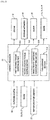
- the control processor 21 is configured to include a microprocessor that is constructed of a CPU, ROM, RAM, and the like, and, as illustrated in Fig. 1 and Fig. 2 , is connected to the radars 15, 16, 17, the outdoor camera 18, the map information memory 19, and the like, and is configured to receive various types of the information.
- control processor 21 can command the engine 2, the steering actuator 14, the alarm 20, and the brakes 71, 7r, 91, 9r on the basis of the received information.
- the control processor 21 particularly includes a first steering torque exerting section (a first steering force exerting section) 211, a second steering torque exerting section (a second steering force exerting section) 212, a characteristic switching position setting section (a switching position setting section) 213, and a table storage section 214. These will be described below.
- Fig. 3 is a schematic view illustrating the detection of the mark lines DL L , DL R and the road end E RL by the outdoor camera 18.
- the outdoor camera 18, which is particularly provided on a cabin inner side of a front windshield of the vehicle 1, can detect a front range ⁇ 18 of the vehicle 1.
- the vehicle 1 travels on a left travel lane LN.
- a left mark line (a roadway outer line) DL L is provided on a left side of the lane LN
- a right mark line (a roadway center line) DL R is provided on a right side of the lane LN.
- the road end E RL is provided on a further left side of the roadway outer line DL L .
- the outdoor camera 18 can at least detect the roadway outer line DL L , the roadway center line DL R , and the road end E RL . Note that respective outer ends E DLL , E DLR of the mark lines DL L , DL R can also be detected in the detection of the roadway outer line DL L and the roadway center line DL R by the outdoor camera 18.
- the road end E RL is a boundary between a side strip (or a side area) on the left side (the outer side) of the roadway outer line DL L and an off-road OR.
- the control processor 21 stores various modes of the road end E RL corresponding to road conditions.
- the control processor 21 conclusively determines the road end E RL in consideration of the road information and the like acquired from the map information memory 19.
- a right mark line (a roadway outer line) DL R may be provided on a right side of the lane LN
- a left mark line (a roadway center line) DL L may be provided on a left side of the lane LN.
- the road end E RL is provided on a further right side of the roadway outer line DL R .
- the outdoor camera 18 can at least detect the roadway outer line DL R , the roadway center line DL L , and the road end E RL .
- Respective outer ends E DLL , E DLR of the mark lines DL L , DL R can also be detected.
- the road end E RL may a boundary between a side strip (or a side area) on the right side (the outer side) of the roadway outer line DL R and an off-road.
- the side strip (or the side area) may be a cycle path on the right side (the outer side) of the roadway outer line DL R , and the off-road OR may be a side walk.
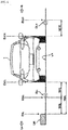
- Fig. 4 is a schematic view illustrating positions of the vehicle 1, the mark lines DL L , DL R , and the road end E RL in a state where the vehicle 1 is seen from the rear side.
- the vehicle 1 travels on the left lane LN, as requested in a country such as Japan.
- the following description also applies mutatis mutandis to the case where the vehicle 1 travels on the right lane, as requested in a country such as Germany, by e.g. interchanging the "left" and "right".
- the vehicle 1 travels on the lane LN.
- the roadway outer line DL L which is detected by the outdoor camera 18, exists on a left side of the vehicle 1, and the road end E RL exists on the further left side.
- the off-road OR on an outer side of the road end E RL is made one step higher than the lane LN and the side strip ( or the side area) between the roadway outer line DL L and the road end E RL by a curb.
- the roadway center line DL R exists on a right side of the vehicle 1.
- a width between a vehicle left end E VCL as a left end of the vehicle 1 (a lateral end of the vehicle 1) and the left mark line outer end E DLL of the roadway outer line DL L is W1L.
- a width between the vehicle left end E VCL of the vehicle 1 and the road end E RL is W2L.
- a width between a vehicle right end E VCR as a right end of the vehicle 1 and the right mark line outer end E DLR of the roadway center line DL R is W1R.
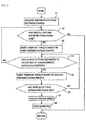
- Fig. 5 is a flowchart illustrating the first steering control that is executed by the control processor 21.
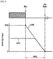
- Fig. 6 is a schematic chart illustrating a relationship between the position of each of the roadway outer line DL L and the road end E RL and the steering torque to be exerted.
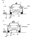
- Fig. 7(a) is a schematic view illustrating a state where the vehicle 1 starts moving into the side strip( or the side area) beyond the roadway outer line DL L
- Fig. 7(b) is a schematic view illustrating a state where the vehicle 1 further moves to the road end E RL side in the side strip (or the side area).
- the control processor 21 acquires detection results (a detection result of each of the roadway outer line DL L , the roadway center line DL R , and the road end E RL ) from the outdoor camera 18 (step S1) . Based on the acquired detection results, the control processor 21 calculates each of the values W1L, W1R, W2L, W3L illustrated in Fig. 4 .
- the flowchart illustrated in Fig. 5 illustrates the control that is executed by the control processor 21 in the case where the calculated value W3L (the width of the side strip) is larger than a specified value that is defined in advance.
- the control processor 21 determines whether the vehicle left end E VCL has moved (departed) to the road end E RL side from the roadway outer line DL L (step S2). If the control processor 21 determines that the vehicle left end E VCL has not departed to the road end E RL side from the roadway outer line DL L (step S2: NO), the processing returns.
- the first steering torque exerting section 211 commands the steering actuator 14 to exert the steering torque (a first steering force) based on a first steering characteristic (step S3).
- the steering actuator 14 thus commanded exerts the steering torque to bring the vehicle 1, which is about to depart to the road end E RL side as indicated by an arrow A, back to a center side of the lane LN as indicated by an arrow ST1.
- a first steering characteristic CH1 is a characteristic in which the steering torque is set in a manner to correspond to a position in a direction toward the road end E RL with the left mark line outer end E DLL of the roadway outer line DL L as an origin. More specifically, the first steering characteristic CH1 has: a torque increased section (a steering force increased section) L1 in which the steering torque is gradually increased to a first torque value TO1 in a range from the left mark line outer end E DLL to a position P2; and a torque maintained section L2 in which the first torque value TO1 is maintained in a range from the position P2 to a position (a characteristic switching position) P1.
- a slope of the torque increased section L1 in the first steering characteristic CH1 is (TO1/W6) .
- a width W4 from the left mark line outer end E DLL to the characteristic switching position P1 corresponds to the "specified value that is defined in advance" described above.
- the control processor 21 determines whether the vehicle left end E VCL has moved (departed) to the outer side (the road end E RL side) from the characteristic switching position P1 (step S4). If the control processor 21 determines that the vehicle left end E VCL has not moved (departed) to the road end E RL side from the characteristic switching position P1 (step S4: NO), the processing returns to the determination in step S2.
- step S2 if, due to the exertion of the steering torque (the first steering force) based on the first steering characteristic CH1, the vehicle left end E VCL of the vehicle 1 moves back to the right side (the center side of the lane LN) of the left mark line outer end E DLL of the roadway outer line DL L , the determination of "NO" is made in step S2, and the processing returns. Accordingly, the command for the steering actuator 14 to exert the steering torque is canceled.
- characteristic switching position setting section 213 in the control processor 21 sets the characteristic switching position P1, and the detailed description thereon will be made later.
- the second steering torque exerting section 212 commands the steering actuator 14 to exert the steering torque (a second steering force) based on a second steering characteristic CH2 (step S5). That is, the control processor 21 commands the steering actuator 14 to switch from the first steering characteristic CH1 to the second steering characteristic CH2 so as to exert the steering torque (the second steering force).
- the steering actuator 14 which has received the command, exerts the higher steering torque (second steering force) than before (than the first steering force) to bring the vehicle 1, which is about to depart further to the road end E RL side as indicated by an arrow B, back to the center side of the lane LN as indicated by an arrow ST2.
- the second steering characteristic CH2 is a characteristic in which the steering torque is set in the manner to correspond to the position in the direction toward the road end E RL with a position P3 as the origin. More specifically, the second steering characteristic CH2 has: a torque increased section (a steering force increased section) L3 in which the steering torque is gradually increased to a second torque value TO2 in a range from the position P3 to the road end E RL ; and a torque maintained section L4 in which the second torque value TO2 is maintained in a range on the outer side of the road end E RL (the off-road OR) .
- a slope of the torque increased section L3 in the second steering characteristic CH2 is set as (TO2/W7), and, as an example in this embodiment, is set to be substantially the same as the slope (TO1/W6) of the torque increased section L1 in the first steering characteristic CH1 described above.
- the range where the steering torque based on the second steering characteristic CH2 is exerted is actually a range with a width W5 from the characteristic switching position P1 to the road end E RL .
- a width W8 from the left mark line outer end E DLL to the position P3 as the origin of the second steering characteristic CH2 varies in accordance with the width W3L of the side strip (or the side area). That is, in this embodiment, as an example, in the second steering characteristic CH2, the position P3 as the origin thereof moves in a width direction (a lateral direction) in a state where the slope of the torque increased section L3 and the like are maintained. The description thereon will be made later.
- step S6 determines whether the vehicle left end E VCL has approached the road end E RL. If the control processor 21 determines that the vehicle left end E VCL has not approached the road end E RL (step S6: NO), the processing returns to the determination in step S4. Note that a definition of "approach" in the determination in step S6 can be changed in accordance with the road condition, a vehicle speed, or the like. As an example, a state where the vehicle left end E VCL approaches the road end E RL within 1 to 5 cm can be set.
- step S4 if, due to the exertion of the steering torque (the second steering force) based on the second steering characteristic CH2, the vehicle left end E VCL of the vehicle 1 moves back to the right side (the center side of the lane LN) of the characteristic switching position P1, the determination of "NO" is made in step S4, and the processing further returns the determination in step S2.
- step S2 the determination of "NO" is made in step S2, and the processing returns. Accordingly, the command for the steering actuator 14 to exert the steering torque is canceled.
- step S6 determines that the vehicle left end E VCL has approached the road end E RL (step S6: YES)
- the control processor 21 actuates the brakes 71, 7r, 91, 9r to reduce a rotational frequency of the engine 2 and thereby reduce the vehicle speed (step S7), and commands the alarm 20 to issue the warning (step S8) .
- Fig. 8 is a flowchart illustrating the second steering control that is executed by the control processor 21.
- Fig. 9 is a schematic chart illustrating the relationship between the position of each of the left mark line outer end E DLL of the roadway outer line DL L and the road end E RL and the steering torque to be exerted.
- the control processor 21 acquires the detection results (the detection result of each of the roadway outer line DL L , the roadway center line DL R , and the road end E RL ) from the outdoor camera 18 (step S11) . Similar to the above, based on the acquired detection results, the control processor 21 calculates each of the values W1L, W1R, W2L, W3L illustrated in Fig. 4 .
- the flowchart illustrated in Fig. 8 illustrates the control that is executed by the control processor 21 in the case where the calculated value W3L (the width of the side strip) is smaller than the specified value that is defined in advance.
- the control processor 21 determines whether the vehicle left end E VCL has moved (departed) to the road end E RL side from the roadway outer line DL L (step S12). If the control processor 21 determines that the vehicle left end E VCL has not departed to the road end E RL side from the roadway outer line DL L (step S12: NO), the processing returns.
- the second steering torque exerting section 212 commands the steering actuator 14 to exert the steering torque (the second steering force) based on the second steering characteristic CH2 (step S13).
- a reason why the steering actuator 14 is commanded to exert the steering torque based on the second steering characteristic CH2 from the beginning instead of the steering torque based on the first steering characteristic CH1 is that the width of the side strip (or the side area) is narrower than the specified value.
- the position P3 as the origin of the second steering characteristic CH2 is set in a manner to match the left mark line outer end E DLL of the roadway outer line DL L .
- the second steering characteristic CH2 illustrated in Fig. 9 is similar to that described above. However, depending on the width W3L of the side strip (or the side area), a setting range (a width W7 in Fig. 6 ) of the torque increased section L3 in the second steering characteristic CH2 can also be set narrow according to the width W3L of the side strip (or the side area).
- step S14 the control processor 21 determines whether the vehicle left end E VCL has approached the road end E RL (step S14). If the control processor 21 determines that the vehicle left end E VCL has not approached the road end E RL (step S14: NO), the processing returns to the determination in step S12. Note that the definition of "approach" in the determination in step S14 is the same as that described above.
- step S12 in the case where the processing returns to the determination in step S12, if, due to the exertion of the steering torque (the second steering force) based on the second steering characteristic CH2, the vehicle left end E VCL of the vehicle 1 moves back to the right side (the center side of the lane LN) of the left mark line outer end E DLL of the roadway outer line DL L , the determination of "NO" is made in step S12, and the processing returns. Accordingly, the command for the steering actuator 14 to exert the steering torque is canceled.
- step S14 determines that the vehicle left end E VCL has approached the road end E RL (step S14: YES), similar to the above, the control processor 21 actuates the brakes 71, 7r, 91, 9r to reduce the rotational frequency of the engine 2 and thereby reduce the vehicle speed (step S15), and commands the alarm 20 to issue the warning (step S16).
- the first steering control in which the steering torque based on the first steering characteristic CH1 or the steering torque based on the second steering characteristic CH2 is exerted in accordance with a degree of the departure of the vehicle 1, or the second steering control, in which the steering torque based on the second steering characteristic CH2 is exerted initially from the time when the vehicle 1 departs the roadway outer line DL L , is selectively executed.
- Such selection of the control is made on the basis of whether the width W3L of the side strip (or the side area) is wider or narrower than the specified value. This method for selecting will be described with reference to Fig. 10 to Fig. 12 .
- Fig. 10 is a flowchart illustrating the method for selecting the first steering control or the second steering control by the control processor 21.
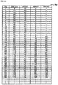
- Fig. 11 is a schematic view illustrating a reference table Tab that is referred when the control processor 21 selects the control.
- Fig. 12(a) is a schematic chart illustrating the positions of the roadway outer line DL L and the road end E RL , the first steering characteristic CH1, and the second steering characteristic CH2 in the case where the width W3L of the side strip (or the side area) is relatively wide, and Fig.
- FIG. 12(b) is a schematic chart illustrating the positions of the roadway outer line DL L and the road end E RL , the first steering characteristic CH1, and the second steering characteristic CH2 in the case where the width W3L of the side strip (or the side area) is narrower than that in the state illustrated in Fig. 12(a) .
- the control processor 21 acquires the detection results (the detection result of each of the roadway outer line DL L , the roadway center line DL R , and the road end E RL ) from the outdoor camera 18 (step S21). Then, from the acquired detection results, the control processor 21 determines whether the roadway outer line DL L is detected (step S22) . If the control processor 21 determines that the roadway outer line DL L is not detected (step S22: NO), the processing returns.
- step S22 determines that the roadway outer line DL L is detected (step S22: YES)
- the control processor 21 sets the first steering characteristic CH1 with the left mark line outer end E DLL of the roadway outer line DL L as the origin (step S23). That is, as illustrated in Fig. 12(a) and Fig. 12(b) , the control processor 21 sets the first steering characteristic CH1 with the left mark line outer end E DLL as the origin.
- the control processor 21 determines whether the road end E RL is detected (step S24). If the control processor 21 determines that the road end E RL is not detected (step S24: NO), the processing returns.
- the road end E RL is not detected, for example, a case where the vehicle 1 travels on a road with two or more lanes each way and the vehicle 1 travels on the lane LN that is a fast lane on the center side rather than a slow lane on the end side of the road is considered.
- step S24 determines that the road end E RL is detected (step S24: YES)
- the control processor 21 calculates the width of the side strip (or the side area), that is, the width W3L between the left mark line outer end E DLL of the roadway outer line DL L and the road end E RL (step S25). Then, the control processor 21 determines whether the calculated width W3L is wider than the setting range (the width W7) of the torque increased section L3 in the second steering characteristic CH2 (step S26) .
- control processor 21 determines that the width W3L is wider than the width W7 (step S26: YES)
- the control processor 21 executes the first steering control and sets the characteristic switching position P1 (step S27), and then sets the second steering characteristic CH2 with the characteristic switching position P1 as the origin (step S28) .
- the control processor 21 sets the characteristic switching position P1 with reference to the reference table Tab in Fig. 11 , which is stored in the table storage section 214 in advance. More specifically, the control processor 21 sets W4 as the position of the characteristic switching position P1 by using stored data on No. 15 onward in the reference table Tab illustrated in Fig. 11 . Note that a processor of each numerical value in the reference table is "cm" .
- W3L is set with 5 cm increments.
- the numerical value of W3L less than 5 cm is rounded down to set the characteristic switching position P1.
- step S26 determines that the width W3L is equal to or narrower than the width W7 (step S26: NO)
- the control processor 21 executes the second steering control, cancels the first steering characteristic CH1 set in step S22 (step S29), and sets the second steering characteristic CH2 with the left mark line outer end E DLL of the roadway outer line DL L as the origin (step S30). That is, the steering characteristic as illustrated in Fig. 9 is set.
- the control processor 21 determines the execution of the second steering control also on the basis of the reference table Tab. In this case, the control processor 21 refers to No. 1 to 14 in Fig. 11 .
- the control processor 21 selects the first steering control or the second steering control.
- the control processor 21 selects the first steering control or the second steering control with reference to the reference table Tab, which is stored in the table storage section 214.
- the reference table Tab can be adopted by correcting the values therein in accordance with the travel speed of the vehicle 1 during the selection of the control, or the like. More specifically, in the case where the vehicle speed is high, the values of the reference table Tab may be corrected to narrow the width W4 in comparison with that in the case where the vehicle speed is low. In this way, the second steering control, in which the steering torque based on the second steering characteristic CH2 is exerted, may be executed at an early stage of the departure.
- the vehicle speed is reduced, and the warning is issued.
- these are not essential. Alternatively, only one of the reduction of the vehicle speed and the issuance of the warning may be made.
- the torque maintained section L4 is also provided in the second steering characteristic CH2.
- the torque maintained section L4 is not essential. For example, in the case where the vehicle left end of the vehicle comes in contact with or is beyond the road end, the steering torque may not be exerted, and the vehicle may be stopped.
- the engine 2 is adopted as the power source of the vehicle 1.
- the present invention is not limited thereto.
- a case where an electric motor serves as a drive source can also be applied to the present invention.
- the present invention is not limited thereto.
- the present invention can also be applied to a case of right-hand traffic.
- the first steering control or the second steering control can be selected with the width of the side strip (or a side area) between the mark line on the right side and the road end, which is located further on the right side of the mark line, as a reference.
Landscapes
- Engineering & Computer Science (AREA)
- Mechanical Engineering (AREA)
- Transportation (AREA)
- Chemical & Material Sciences (AREA)
- Combustion & Propulsion (AREA)
- Automation & Control Theory (AREA)
- Human Computer Interaction (AREA)
- Steering Control In Accordance With Driving Conditions (AREA)
- Control Of Driving Devices And Active Controlling Of Vehicle (AREA)
Abstract
Description
- The present invention relates to a vehicle control apparatus, a vehicle, a vehicle control method, and a computer program product and, in particular, to a steering assist technique.
- A vehicle such as an automobile, to which a steering assist technique for avoiding lane departure is applied, has been available. For example, Japanese Patent Laid-Open publication No.
2017-174017 - In the technique disclosed in the above-described patent document, an on-board camera is used to detect a roadway outer line (a mark line) and a road end. Then, in accordance with a width between the roadway outer line and the road end, a steering force exertion start position is set on an inner side (a lane side) of the roadway outer line.
- With the technique disclosed in the above-described patent document, the steering force that urges the vehicle to move back into the lane is exerted when the vehicle approaches the roadway outer line. Thus, it is possible to prevent the vehicle from departing to the road end side beyond the roadway outer line.
- However, the technique disclosed in the above-described patent document may cause a driver to have senses of discomfort and irritation and may give the driver considerable stress.
- More specifically, in the technique disclosed in the above-described patent document, in a situation where the vehicle travels on the lane while keeping a substantially constant distance from the roadway outer line, the steering force is exerted to avoid the departure, or an amount of the exerted steering force changes every time the width between the roadway outer line and the road end changes. With the technique disclosed in the above-described patent document, which may cause such a circumstance, the driver acquires the senses of discomfort and irritation. Consequently, the technique may cause the driver to receive the significant stress.
- The present invention has been made to solve the problem as described above, and therefore an object of the present invention is preventing departure to an off-road, while hindering a driver from having senses of discomfort and irritation and receiving stress.
- To achieve this object, a vehicle control apparatus according to an aspect of the present invention is a vehicle control apparatus which includes: a steering force generating section configured to generate the steering force for a vehicle; a line detecting section configured to detect a line being on a road and extending along a travel direction of the vehicle on one lateral side of the vehicle; a road end detecting section configured to detect a road end on the one lateral side; and a vehicle control processor. The vehicle control processor is configured to receive a detection result from each of the line detecting section and the road end detecting section, command the steering force generating section to exert a first steering force, which is the steering force based on a first steering characteristic, in the case where the vehicle departs toward the road end from the line, and command the steering force generating section to exert a second steering force, which is the larger steering force than the first steering force, on the basis of a second steering characteristic differing from the first steering characteristic in the case where the vehicle departs toward the road end from the line. The first steering force is exerted with an outer end of the line on the road end side as an origin. The second steering force is exerted with the road end as a reference and a position between the outer end and the road end as an origin.
- Particularly, the vehicle control processor is configured to selectively execute, in accordance with a width between the line and the road end, a first steering control or a second steering control. In the first steering control, the steering force generating section generates the first steering force in the case where a lateral end, particularly a right end, of the vehicle is located within a range from the line to a specified position between the line and the road end, and the steering force generating section generates the second steering force in the case where the lateral end of the vehicle is located within a range from the specified position to the road end. In the second steering control, the steering force generating section generates the second steering force in the case where the lateral end of the vehicle is located within a range from the line to the road end.
- Further particularly, the vehicle control processor is further configured to set the specified position closer to the road end as the width is larger and/or set the specified position closer to the line as the width is smaller.
- Further particularly, each of the first steering characteristic and the second steering characteristic has a steering force increased section in which the steering force is increased or gradually increased from the line toward the road end.
- Further particularly, the vehicle control processor is configured to decelerate the vehicle and/or warn, in the case where the vehicle approaches the road end.
- Further particularly, the line detecting section is configured to detect the line on a right side of the vehicle. The road end detecting section is configured to detect the road end on the right side of the vehicle.
- Further particularly, a vehicle includes the above vehicle control apparatus.
- Further particularly, the vehicle includes an image capturing device capable of capturing an image of outside of a cabin. The image capturing device has functions of both of the line detecting section and the road end detecting section.
- One aspect of the invention is a vehicle control method which includes: a line detecting step of detecting a line being on a road and extending along a travel direction of a vehicle on one lateral side of the vehicle; a road end detecting step of detecting a road end on the one lateral side; and a steering force exerting step of exerting the steering force on the vehicle. The steering force exerting step includes: a first steering force exerting sub-step of exerting a first steering force, which is the steering force based on a first steering characteristic, in the case where the vehicle departs toward the road end from the line; and a second steering force exerting sub-step of exerting a second steering force, which is the larger steering force than the first steering force, on the basis of a second steering characteristic differing from the first steering characteristic in the case where the vehicle departs toward the road end from the line. The first steering force is the steering force that is exerted with an outer end of the line on the road end side as an origin. The second steering force is the steering force that is exerted with the road end as a reference and a position between the outer end and the road end as an origin.
- Particularly, the steering force exerting step includes selectively executing, in accordance with a width between the line and the road end, a first steering control or a second steering control. In the first steering control, the first steering force is exerted in the case where a lateral end of the vehicle is located within a range from the line to a specified position between the line and the road end, and the second steering force is exerted in the case where the lateral end of the vehicle is located within a range from the specified position to the road end. In the second steering control, the second steering force is exerted in the case where the lateral end of the vehicle is located within a range from the line to the road end.
- Further particularly, the steering force exerting step further includes: a switching position setting sub-step of setting the specified position closer to the road end as the width is larger and/or setting the specified position closer to the line as the width is smaller.
- Further particularly, each of the first steering characteristic and the second steering characteristic has a steering force increased section in which the steering force is increased or gradually increased from the line toward the road end.
- Further particularly, the method further includes decelerating the vehicle and/or warning, in the case where the vehicle approaches the road end.
- Further particularly, the line is on a right side of the vehicle. The road end is on the right side of the vehicle.
- Further particularly, a computer program product includes computer readable instructions which, when loaded and executed on a suitable system, perform the above vehicle control method.
- One aspect of the invention is a vehicle control apparatus that exerts a steering force for suppressing departure of a vehicle to an off-road on the vehicle in accordance with a travel situation and includes:
- a steering force generating section that generates the steering force for the vehicle;
- a mark line detecting section that detects a mark line extending along a travel direction of the vehicle on one lateral side of the vehicle;
- a road end detecting section that detects a road end on the one lateral side, the road end being adjacent to an outer side of the vehicle from the mark line and extending along the travel direction; and
- a vehicle control processor that successively receives a detection result from each of the mark line detecting section and the road end detecting section and, based on the detection results, commands the steering force generating section to exert the steering force on the vehicle. The vehicle control processor includes:
- a first steering force exerting section that commands the steering force generating section to exert a first steering force, which is the steering force based on a first steering characteristic, in the case where the vehicle departs to the road end side from the mark line; and
- a second steering force exerting section that commands the steering force generating section to exert a second steering force, which is the larger steering force than the first steering force, on the basis of a second steering characteristic differing from the first steering characteristic in the case where the vehicle departs to the road end side from the mark line.
- The first steering force is exerted with an outer end on the road end side of the mark line as an origin, and
the second steering force is exerted with the road end as a reference and a position between the outer end and the road end as an origin. - In the above-described vehicle control apparatus, the vehicle control processor commands the steering force generating section to exert the steering force in the case where the vehicle departs the mark line to the road end side. Accordingly, the steering force is not exerted within a range where the vehicle travels on a lane. Thus, unnecessary intervention by the control is prevented, and a driver is hindered from having senses of discomfort and irritation and thus from receiving stress during driving. That is, as long as the vehicle travels on the lane, the exertion of the steering force as in the technique disclosed in the above-described patent document is not made in the above vehicle control apparatus. Thus, even when a width of a side strip is changed, the unnecessary steering force is not exerted, and the steering force is not changed.
- In addition, in the above vehicle control apparatus, the first steering force is exerted with the mark line outer end as the origin, and the second steering force is exerted with the road end as the reference and the position between the mark line outer end and the road end as the origin. Thus, a high degree of safety can be secured while the unnecessary intervention by steering control is prevented. That is, in such a case where the lateral end of the vehicle is located on the mark line, the steering force is not exerted. When the lateral end of the vehicle departs the mark line to the road end side, the steering force is exerted for the first time. Thus, the unnecessary exertion of the steering force can be prevented.
- Therefore, the above vehicle control apparatus prevents departure to the off-road, while hindering the driver from having the senses of discomfort and irritation and receiving the stress.
- In the vehicle control apparatus according to the above aspect,
the vehicle control processor can selectively execute the following in accordance with the width of the side strip between the mark line and the road end: - first steering control in which the steering force generating section generates the first steering force in the case where the lateral end of the vehicle is located within a range from the mark line to a specified position between the mark line and the road end and in which the steering force generating section generates the second steering force in the case where the lateral end of the vehicle is located within a range from the specified position to the road end; or
- second steering control in which the steering force generating section generates the second steering force in the case where the lateral end of the vehicle is located within a range from the mark line to the road end.
- In the vehicle control apparatus that adopts the above configuration, the first steering control or the second steering control is selectively executed in accordance with the width of the side strip. Thus, by selecting a control method in accordance with the travel situation, the high degree of safety can be secured while the intervention by the steering control is minimized.
- More specifically, in the case where the width of the side strip is comparatively wide (relatively wide), the above first steering control is executed to initially exert the first steering force from the mark line side toward the road end side and then exert the second steering force. Accordingly, the high degree of safety can be secured with the minimum intervention by the control corresponding to a degree of the departure of the vehicle. Meanwhile, in the case where the width of the side strip is comparatively narrow (relatively narrow), the second steering force is initially exerted from a time when the vehicle departs the mark line. Thus, the high degree of safety can be secured.
- In the vehicle control apparatus according to the above aspect, the vehicle control processor can further include:
a switching position setting section that sets the specified position to the road end side as the width of the side strip is increased and that sets the specified position to the mark line side as the width of the side strip is reduced during execution of the first steering control. - In the vehicle control apparatus that adopts the above configuration, the region where the first steering force based on the first steering characteristic is exerted and the region where the second steering force based on the second steering characteristic is exerted are switched at the above specified position. Thus, in the case where the vehicle further approaches the road end side, the second steering force, which is clearly large, is exerted, so as to be able to secure the high degree of safety.
- In the vehicle control apparatus according to the above aspect,
each of the first steering characteristic and the second steering characteristic can have a steering force increased section in which the steering force is gradually increased from the mark line side toward the road end side. - In the vehicle control apparatus that adopts the above configuration, the steering force is gradually increased when the vehicle departs from the mark line side toward the road end side. Thus, compared to a case where the large steering force is exerted all at once immediately after the vehicle departs the mark line, it is possible to hinder the driver from receiving the stress.
- In the vehicle control apparatus according to the above aspect, the vehicle control processor can make at least one of a reduction of a vehicle speed and issuance of a warning in the case where the vehicle departs to such a state of approaching the road end.
- In the vehicle control apparatus that adopts the above configuration, in the case where the vehicle approaches the road end, at least one of the reduction of the vehicle speed and the issuance of the warning is made to prevent the departure to the off-road. Thus, the high degree of safety can be secured.
- In the vehicle control apparatus according to the above aspect, the vehicle can include an image capturing device capable of capturing an image of outside of a cabin, and the image capturing device can have functions of both of the mark line detecting section and the road end detecting section.
- In the vehicle control apparatus that adopts the above configuration, the image capturing device has the functions of both of the mark line detecting section and the road end detecting section. Thus, compared to a case where separate devices are provided for the sections, manufacturing cost of the vehicle can be reduced. In addition, it is possible to suppress a space for providing the mark line detecting section and the road end detecting section in the vehicle to be small.
- A vehicle control method according to another aspect of the present invention is a vehicle control method that exerts a steering force for suppressing departure of a vehicle to an off-road on the vehicle in accordance with a travel situation, and includes: a mark line detecting step of detecting a mark line extending along a travel direction of the vehicle on one lateral side of the vehicle; a road end detecting step of detecting a road end on the one lateral side, the road end being adjacent to an outer side of the vehicle from the mark line and extending along the travel direction; and a steering force exerting step of exerting the steering force on the vehicle on the basis of a detection result detected in each of the mark line detecting step and the road end detecting step. The steering force exerting step includes: a first steering force exerting sub-step of exerting a first steering force, which is the steering force based on a first steering characteristic, in the case where the vehicle departs to the road end side from the mark line; and a second steering force exerting sub-step of exerting a second steering force, which is the larger steering force than the first steering force, on the basis of a second steering characteristic differing from the first steering characteristic in the case where the vehicle departs to the road end side from the mark line. The first steering force is the steering force that is exerted with an outer end on the road end side of the mark line as an origin, and the second steering force is the steering force that is exerted with the road end as a reference and a position between the outer end and the road end as an origin.
- In the above-described vehicle control method, the steering force is exerted in the steering force exerting step in the case where the vehicle departs the mark line to the road end side. Accordingly, in the above vehicle control method, the steering force is not exerted within a range where the vehicle travels on a lane. Thus, the unnecessary intervention by the control is prevented, and the driver is hindered from receiving the senses of discomfort and irritation and thus from receiving stress during driving. That is, as long as the vehicle travels on the lane, the exertion of the steering force as in the technique disclosed in above
Patent document 1 is not made in the above vehicle control method. Thus, even when the width of the side strip is changed, the unnecessary steering force is not exerted, and the steering force is not changed. - In the above vehicle control method, the first steering force is exerted with the mark line outer end as the origin, and the second steering force is exerted with the road end as the reference and the position between the mark line outer end and the road end as the origin. Accordingly, in such a case where the lateral end of the vehicle is located on the mark line, the steering force is not exerted. When the lateral end of the vehicle departs the mark line to the road end side, the steering force is exerted for the first time. Thus, the unnecessary exertion of the steering force can be prevented.
- Therefore, the above vehicle control method prevents the departure to the off-road, while hindering the driver from having the senses of discomfort and irritation and receiving the stress.
- In the vehicle control method according to the above aspect, the following can selectively be executed in the steering force exerting step: first steering control in which, in accordance with the width of the side strip between the mark line and the road end, the first steering force is exerted in the case where the lateral end of the vehicle is located within a range from the mark line to a specified position between the mark line and the road end and in which the second steering force is exerted in the case where the lateral end of the vehicle is located within a range from the specified position to the road end; or second steering control in which the second steering force is exerted in the case where the lateral end of the vehicle is located within a range from the mark line to the road end.
- In the vehicle control method that adopts the above configuration, the first steering control or the second steering control is selectively executed in accordance with the width of the side strip. Thus, by selecting the control method in accordance with the travel situation, the high degree of safety can be secured while the intervention by the steering control is minimized.
- More specifically, in the case where the width of the side strip is comparatively wide (relatively wide), the above first steering control is executed to initially exert the first steering force from the mark line side toward the road end side and then exert the second steering force. Accordingly, the high degree of safety can be secured with the minimum intervention by the control corresponding to the degree of the departure of the vehicle. Meanwhile, in the case where the width of the side strip is comparatively narrow (relatively narrow), the second steering force is initially exerted from a time when the vehicle departs the mark line. Thus, the high degree of safety can be secured.
- In the vehicle control method according to the above aspect, the steering force exerting step can further include: a switching position setting sub-step of setting the specified position to the road end side as the width of the side strip is increased and setting the specified position to the mark line side as the width of the side strip is reduced during execution of the first steering control.
- In the vehicle control method that adopts the above configuration, the region where the first steering force based on the first steering characteristic is exerted and the region where the second steering force based on the second steering characteristic is exerted are switched at the above specified position. Thus, in the case where the vehicle further approaches the road end side, the second steering force, which is clearly large, is exerted, so as to be able to secure the high degree of safety.
- In each of the above aspects, the departure to the off-road is prevented, while hindering the driver from having the senses of discomfort and irritation and receiving the stress.
-
-
Fig. 1 is a schematic view illustrating a schematic configuration of a vehicle according to an embodiment. -
Fig. 2 is a block diagram illustrating a control configuration of the vehicle. -
Fig. 3 is a schematic view illustrating detection of a mark line and a road end by an outdoor camera. -
Fig. 4 is a schematic view illustrating positions of the vehicle, the mark lines, and the road end. -
Fig. 5 is a flowchart illustrating first steering control that is executed by a control processor. -
Fig. 6 is a schematic chart illustrating a relationship between the position of each of the mark line and the road end and steering torque to be exerted. -
Fig. 7(a) is a schematic view illustrating a state where the vehicle starts moving into a side strip( or a side area) beyond the mark line, andFig. 7(b) is a schematic view illustrating a state where the vehicle further moves to a road end side in the side strip (or the side area). -
Fig. 8 is a flowchart illustrating second steering control that is executed by the control processor. -
Fig. 9 is a schematic chart illustrating the relationship between the position of each of the mark line and the road end and the steering torque to be exerted in the case where a width of the side strip (or the side area) is narrower than a specified width. -
Fig. 10 is a flowchart illustrating a method for selecting the first steering control or the second steering control by the control processor. -
Fig. 11 is a schematic view illustrating a reference table that is stored in a table storage section. -
Fig. 12(a) is a schematic chart illustrating the positions of the mark line and the road end, a first steering characteristic, and a second steering characteristic in the case where the width of the side strip (or the side area) is relatively wide, andFig. 12(b) is a schematic chart illustrating the positions of the mark line and the road end, the first steering characteristic, and the second steering characteristic in the case where the road side width is narrower than that in the state illustrated inFig. 12(a) . - A description will hereinafter be made on an embodiment of the present invention with reference to the drawings. Note that the embodiment, which will be described below, is merely one example of the present invention, and thus the present invention is not limited to the following embodiment in any respect except for an essential configuration thereof.
- In the drawings, which will be used in the description below, "Fr", "Re", "Le", and "Ri" respectively indicate a front side (an advancing direction) of a host vehicle, a rear side of the host vehicle, a left side of the host vehicle, and a right side of the host vehicle.
- A description will be made on a schematic configuration of a
vehicle 1 according to this embodiment with reference toFig. 1 andFig. 2 . - As illustrated in
Fig. 1 , thevehicle 1 particularly includes anengine 2 as a power source. As an example of theengine 2, a multi-cylinder gasoline engine is adopted for thevehicle 1 according to this embodiment. - A
transmission 3 is particularly coupled to theengine 2, and adifferential gear 4 is particularly coupled to thetransmission 3. Adriveshaft 5 particularly extends in a lateral direction from thedifferential gear 4. Left and rightfront wheels 61, 6r are attached to ends of thedriveshaft 5. - A
left front brake 71 is provided in a portion of thedriveshaft 5 near the left front wheel 61, and a rightfront brake 7r is provided in a portion of thedriveshaft 5 near theright front wheel 6r. - Left and right
rear wheels 81, 8r are disposed in a rear portion of thevehicle 1. Each of the left and rightrear wheels 81, 8r is attached to a rear arm, which is not illustrated. A left rear brake 91 is provided on a shaft (not illustrated) that axially supports the left rear wheel 81, and a right rear brake 9r is provided on a shaft (not illustrated) that axially supports the rightrear wheel 8r. - As illustrated in
Fig. 1 , in a cabin of thevehicle 1, asteering wheel 10 is disposed in a portion in front of a driver's seat. Thesteering wheel 10 is attached to a tip portion of a steeringshaft 11. The other end of the steeringshaft 11 is connected to asteering gear 12. A steeringactuator 14 is also connected to the steeringshaft 11 and can exert steering torque (a steering force) on the steeringshaft 11. That is, in thevehicle 1, the steeringactuator 14 functions as a steering force generating section that generates the steering force. - A
tie rod 13 is connected to thesteering gear 12. Orientations of thefront wheels 61, 6r are changed in conjunction with lateral movement of thetie rod 13. - As illustrated in
Fig. 1 , thevehicle 1 is provided with one or more, particularly threeradars radars radar 15 is particularly disposed in a front portion of thevehicle 1, and the two remainingradars vehicle 1. Each of theseradars vehicle 1 to the peripheral vehicle. - The
outdoor camera 18 detects a line or a mark line, which is particularly on a road, and a road end ahead of thevehicle 1. That is, in thevehicle 1 according to this embodiment, theoutdoor camera 18 is a mark line detecting section (a roadway outer line detecting section and a roadway center line detecting section) that detects the mark lines (a roadway outer line, a roadway center line, and the like) on both sides of a travel lane and is a road end detecting section that detects the road end located on an off-road side of the mark line. - In addition, the
vehicle 1 is particularly provided with amap information memory 19. Themap information memory 19 stores information on a road where thevehicle 1 travels, and the like. Map information stored in themap information memory 19 particularly includes lane information of the road. - The
vehicle 1 includes analarm 20 capable of issuing a warning to an occupant. Thevehicle 1 is further provided with a control processor (a vehicle control processor) 21. Thecontrol processor 21 is configured to include a microprocessor that is constructed of a CPU, ROM, RAM, and the like, and, as illustrated inFig. 1 andFig. 2 , is connected to theradars outdoor camera 18, themap information memory 19, and the like, and is configured to receive various types of the information. - In addition, the
control processor 21 can command theengine 2, the steeringactuator 14, thealarm 20, and thebrakes - Furthermore, as illustrated in
Fig. 2 , thecontrol processor 21 particularly includes a first steering torque exerting section (a first steering force exerting section) 211, a second steering torque exerting section (a second steering force exerting section) 212, a characteristic switching position setting section (a switching position setting section) 213, and atable storage section 214. These will be described below. - A description will be made on the detection of mark lines DLL, DLR and a road end ERL by the
outdoor camera 18 with reference toFig. 3. Fig. 3 is a schematic view illustrating the detection of the mark lines DLL, DLR and the road end ERL by theoutdoor camera 18. - As illustrated in
Fig. 3 , theoutdoor camera 18, which is particularly provided on a cabin inner side of a front windshield of thevehicle 1, can detect a front range θ18 of thevehicle 1. - Here, in this embodiment, as an example, the
vehicle 1 travels on a left travel lane LN. A left mark line (a roadway outer line) DLL is provided on a left side of the lane LN, and a right mark line (a roadway center line) DLR is provided on a right side of the lane LN. The road end ERL is provided on a further left side of the roadway outer line DLL. - The
outdoor camera 18 can at least detect the roadway outer line DLL, the roadway center line DLR, and the road end ERL. Note that respective outer ends EDLL, EDLR of the mark lines DLL, DLR can also be detected in the detection of the roadway outer line DLL and the roadway center line DLR by theoutdoor camera 18. - Note that the road end ERL is a boundary between a side strip (or a side area) on the left side (the outer side) of the roadway outer line DLL and an off-road OR. The
control processor 21 stores various modes of the road end ERL corresponding to road conditions. Thecontrol processor 21 conclusively determines the road end ERL in consideration of the road information and the like acquired from themap information memory 19. - In the case where the
vehicle 1 travels on a right travel lane LN, a right mark line (a roadway outer line) DLR may be provided on a right side of the lane LN, and a left mark line (a roadway center line) DLL may be provided on a left side of the lane LN. The road end ERL is provided on a further right side of the roadway outer line DLR. Theoutdoor camera 18 can at least detect the roadway outer line DLR, the roadway center line DLL, and the road end ERL. Respective outer ends EDLL, EDLR of the mark lines DLL, DLR can also be detected. The road end ERL may a boundary between a side strip (or a side area) on the right side (the outer side) of the roadway outer line DLR and an off-road. - The side strip (or the side area) may be a cycle path on the right side (the outer side) of the roadway outer line DLR, and the off-road OR may be a side walk.
- Next, a description will be made on a travel situation of the
vehicle 1, which will be assumed as an example, with reference toFig. 4. Fig. 4 is a schematic view illustrating positions of thevehicle 1, the mark lines DLL, DLR, and the road end ERL in a state where thevehicle 1 is seen from the rear side. InFig. 4 , thevehicle 1 travels on the left lane LN, as requested in a country such as Japan. The following description also applies mutatis mutandis to the case where thevehicle 1 travels on the right lane, as requested in a country such as Germany, by e.g. interchanging the "left" and "right". - As illustrated in
Fig. 4 , thevehicle 1 travels on the lane LN. In addition, the roadway outer line DLL, which is detected by theoutdoor camera 18, exists on a left side of thevehicle 1, and the road end ERL exists on the further left side. In this embodiment, as an example, the off-road OR on an outer side of the road end ERL is made one step higher than the lane LN and the side strip ( or the side area) between the roadway outer line DLL and the road end ERL by a curb. In addition, the roadway center line DLR exists on a right side of thevehicle 1. - A width between a vehicle left end EVCL as a left end of the vehicle 1 (a lateral end of the vehicle 1) and the left mark line outer end EDLL of the roadway outer line DLL is W1L. A width between the vehicle left end EVCL of the
vehicle 1 and the road end ERL is W2L. In the situation illustrated inFig. 4 , a width of the side strip( or the side area) is W3L (= W2L - W1L). - Meanwhile, a width between a vehicle right end EVCR as a right end of the
vehicle 1 and the right mark line outer end EDLR of the roadway center line DLR is W1R. - A description will be made on steering control (first steering control) in the case where the
control processor 21 determines that the width W3L of the side strip( or the side area) is relatively wide with reference toFig. 5 to Fig. 7 .Fig. 5 is a flowchart illustrating the first steering control that is executed by thecontrol processor 21.Fig. 6 is a schematic chart illustrating a relationship between the position of each of the roadway outer line DLL and the road end ERL and the steering torque to be exerted.Fig. 7(a) is a schematic view illustrating a state where thevehicle 1 starts moving into the side strip( or the side area) beyond the roadway outer line DLL, andFig. 7(b) is a schematic view illustrating a state where thevehicle 1 further moves to the road end ERL side in the side strip (or the side area). - As illustrated in
Fig. 5 , thecontrol processor 21 acquires detection results (a detection result of each of the roadway outer line DLL, the roadway center line DLR, and the road end ERL) from the outdoor camera 18 (step S1) . Based on the acquired detection results, thecontrol processor 21 calculates each of the values W1L, W1R, W2L, W3L illustrated inFig. 4 . The flowchart illustrated inFig. 5 illustrates the control that is executed by thecontrol processor 21 in the case where the calculated value W3L (the width of the side strip) is larger than a specified value that is defined in advance. - Referring back to
Fig. 5 , thecontrol processor 21 determines whether the vehicle left end EVCL has moved (departed) to the road end ERL side from the roadway outer line DLL (step S2). If thecontrol processor 21 determines that the vehicle left end EVCL has not departed to the road end ERL side from the roadway outer line DLL (step S2: NO), the processing returns. - On the other hand, if the
control processor 21 determines that the vehicle left end EVCL has departed to the road end ERL side from the roadway outer line DLL (step S2: YES), the first steeringtorque exerting section 211 commands thesteering actuator 14 to exert the steering torque (a first steering force) based on a first steering characteristic (step S3). As illustrated inFig. 7(a) , the steeringactuator 14 thus commanded exerts the steering torque to bring thevehicle 1, which is about to depart to the road end ERL side as indicated by an arrow A, back to a center side of the lane LN as indicated by an arrow ST1. - As illustrated in
Fig. 6 , a first steering characteristic CH1 is a characteristic in which the steering torque is set in a manner to correspond to a position in a direction toward the road end ERL with the left mark line outer end EDLL of the roadway outer line DLL as an origin. More specifically, the first steering characteristic CH1 has: a torque increased section (a steering force increased section) L1 in which the steering torque is gradually increased to a first torque value TO1 in a range from the left mark line outer end EDLL to a position P2; and a torque maintained section L2 in which the first torque value TO1 is maintained in a range from the position P2 to a position (a characteristic switching position) P1. - Note that, as illustrated in
Fig. 6 , in this embodiment, a slope of the torque increased section L1 in the first steering characteristic CH1 is (TO1/W6) . In addition, a width W4 from the left mark line outer end EDLL to the characteristic switching position P1 corresponds to the "specified value that is defined in advance" described above. - Referring back to
Fig. 5 , in the state of commanding thesteering actuator 14 to exert the steering torque (the first steering force) based on the first steering characteristic CH1, thecontrol processor 21 determines whether the vehicle left end EVCL has moved (departed) to the outer side (the road end ERL side) from the characteristic switching position P1 (step S4). If thecontrol processor 21 determines that the vehicle left end EVCL has not moved (departed) to the road end ERL side from the characteristic switching position P1 (step S4: NO), the processing returns to the determination in step S2. - Here, if, due to the exertion of the steering torque (the first steering force) based on the first steering characteristic CH1, the vehicle left end EVCL of the
vehicle 1 moves back to the right side (the center side of the lane LN) of the left mark line outer end EDLL of the roadway outer line DLL, the determination of "NO" is made in step S2, and the processing returns. Accordingly, the command for thesteering actuator 14 to exert the steering torque is canceled. - Note that the characteristic switching
position setting section 213 in thecontrol processor 21 sets the characteristic switching position P1, and the detailed description thereon will be made later. - On the other hand, if the
control processor 21 determines that the vehicle left end EVCL has departed to the road end ERL side from the characteristic switching position P1 (step S4: YES), the second steeringtorque exerting section 212 commands thesteering actuator 14 to exert the steering torque (a second steering force) based on a second steering characteristic CH2 (step S5). That is, thecontrol processor 21 commands thesteering actuator 14 to switch from the first steering characteristic CH1 to the second steering characteristic CH2 so as to exert the steering torque (the second steering force). - As illustrated in
Fig. 7(b) , the steeringactuator 14, which has received the command, exerts the higher steering torque (second steering force) than before (than the first steering force) to bring thevehicle 1, which is about to depart further to the road end ERL side as indicated by an arrow B, back to the center side of the lane LN as indicated by an arrow ST2. - As illustrated in
Fig. 6 , the second steering characteristic CH2 is a characteristic in which the steering torque is set in the manner to correspond to the position in the direction toward the road end ERL with a position P3 as the origin. More specifically, the second steering characteristic CH2 has: a torque increased section (a steering force increased section) L3 in which the steering torque is gradually increased to a second torque value TO2 in a range from the position P3 to the road end ERL; and a torque maintained section L4 in which the second torque value TO2 is maintained in a range on the outer side of the road end ERL (the off-road OR) . - Note that, as illustrated in
Fig. 6 , in this embodiment, a slope of the torque increased section L3 in the second steering characteristic CH2 is set as (TO2/W7), and, as an example in this embodiment, is set to be substantially the same as the slope (TO1/W6) of the torque increased section L1 in the first steering characteristic CH1 described above. - In addition, because the first steering characteristic CH1 and the second steering characteristic CH2 overlap each other in the range from the position P3 to the characteristic switching position P1, the range where the steering torque based on the second steering characteristic CH2 is exerted is actually a range with a width W5 from the characteristic switching position P1 to the road end ERL.
- Furthermore, a width W8 from the left mark line outer end EDLL to the position P3 as the origin of the second steering characteristic CH2 varies in accordance with the width W3L of the side strip (or the side area). That is, in this embodiment, as an example, in the second steering characteristic CH2, the position P3 as the origin thereof moves in a width direction (a lateral direction) in a state where the slope of the torque increased section L3 and the like are maintained. The description thereon will be made later.
- Referring back to
Fig. 5 , in the state of commanding thesteering actuator 14 to exert the steering torque (the second steering force) based on the second steering characteristic CH2, thecontrol processor 21 determines whether the vehicle left end EVCL has approached the road end ERL (step S6). If thecontrol processor 21 determines that the vehicle left end EVCL has not approached the road end ERL (step S6: NO), the processing returns to the determination in step S4. Note that a definition of "approach" in the determination in step S6 can be changed in accordance with the road condition, a vehicle speed, or the like. As an example, a state where the vehicle left end EVCL approaches the road end ERL within 1 to 5 cm can be set. - Here, in the case where the processing returns to the determination in step S4, if, due to the exertion of the steering torque (the second steering force) based on the second steering characteristic CH2, the vehicle left end EVCL of the
vehicle 1 moves back to the right side (the center side of the lane LN) of the characteristic switching position P1, the determination of "NO" is made in step S4, and the processing further returns the determination in step S2. Then, similar to the above, if, due to the exertion of the steering torque (the second steering force) based on the second steering characteristic CH2, the vehicle left end EVCL of thevehicle 1 moves back to the right side (the center side of the lane LN) of the left mark line outer end EDLL of the roadway outer line DLL, the determination of "NO" is made in step S2, and the processing returns. Accordingly, the command for thesteering actuator 14 to exert the steering torque is canceled. - On the other hand, if the
control processor 21 determines that the vehicle left end EVCL has approached the road end ERL (step S6: YES), thecontrol processor 21 actuates thebrakes engine 2 and thereby reduce the vehicle speed (step S7), and commands thealarm 20 to issue the warning (step S8) . - A description will be made on steering control (second steering control) in the case where the
control processor 21 determines that the width W3L of the side strip (or the side area) is relatively narrow with reference toFig. 8 andFig. 9 .Fig. 8 is a flowchart illustrating the second steering control that is executed by thecontrol processor 21.Fig. 9 is a schematic chart illustrating the relationship between the position of each of the left mark line outer end EDLL of the roadway outer line DLL and the road end ERL and the steering torque to be exerted. - As illustrated in
Fig. 8 , thecontrol processor 21 acquires the detection results (the detection result of each of the roadway outer line DLL, the roadway center line DLR, and the road end ERL) from the outdoor camera 18 (step S11) . Similar to the above, based on the acquired detection results, thecontrol processor 21 calculates each of the values W1L, W1R, W2L, W3L illustrated inFig. 4 . The flowchart illustrated inFig. 8 illustrates the control that is executed by thecontrol processor 21 in the case where the calculated value W3L (the width of the side strip) is smaller than the specified value that is defined in advance. - Referring back to
Fig. 8 , thecontrol processor 21 determines whether the vehicle left end EVCL has moved (departed) to the road end ERL side from the roadway outer line DLL (step S12). If thecontrol processor 21 determines that the vehicle left end EVCL has not departed to the road end ERL side from the roadway outer line DLL (step S12: NO), the processing returns. - On the other hand, if the
control processor 21 determines that the vehicle left end EVCL has departed to the road end ERL side from the roadway outer line DLL (step S12: YES), the second steeringtorque exerting section 212 commands thesteering actuator 14 to exert the steering torque (the second steering force) based on the second steering characteristic CH2 (step S13). Here, in this control, a reason why thesteering actuator 14 is commanded to exert the steering torque based on the second steering characteristic CH2 from the beginning instead of the steering torque based on the first steering characteristic CH1 is that the width of the side strip (or the side area) is narrower than the specified value. - That is, as illustrated in
Fig. 9 , in this control, the position P3 as the origin of the second steering characteristic CH2 is set in a manner to match the left mark line outer end EDLL of the roadway outer line DLL. The second steering characteristic CH2 illustrated inFig. 9 is similar to that described above. However, depending on the width W3L of the side strip (or the side area), a setting range (a width W7 inFig. 6 ) of the torque increased section L3 in the second steering characteristic CH2 can also be set narrow according to the width W3L of the side strip (or the side area). - Referring back to
Fig. 8 , in the state of commanding thesteering actuator 14 to exert the steering torque (the second steering force) based on the second steering characteristic CH2, thecontrol processor 21 determines whether the vehicle left end EVCL has approached the road end ERL (step S14). If thecontrol processor 21 determines that the vehicle left end EVCL has not approached the road end ERL (step S14: NO), the processing returns to the determination in step S12. Note that the definition of "approach" in the determination in step S14 is the same as that described above. - Here, in the case where the processing returns to the determination in step S12, if, due to the exertion of the steering torque (the second steering force) based on the second steering characteristic CH2, the vehicle left end EVCL of the
vehicle 1 moves back to the right side (the center side of the lane LN) of the left mark line outer end EDLL of the roadway outer line DLL, the determination of "NO" is made in step S12, and the processing returns. Accordingly, the command for thesteering actuator 14 to exert the steering torque is canceled. - On the other hand, if the
control processor 21 determines that the vehicle left end EVCL has approached the road end ERL (step S14: YES), similar to the above, thecontrol processor 21 actuates thebrakes engine 2 and thereby reduce the vehicle speed (step S15), and commands thealarm 20 to issue the warning (step S16). - As described above, in the steering control of the
vehicle 1 according to this embodiment, the first steering control, in which the steering torque based on the first steering characteristic CH1 or the steering torque based on the second steering characteristic CH2 is exerted in accordance with a degree of the departure of thevehicle 1, or the second steering control, in which the steering torque based on the second steering characteristic CH2 is exerted initially from the time when thevehicle 1 departs the roadway outer line DLL, is selectively executed. Such selection of the control is made on the basis of whether the width W3L of the side strip (or the side area) is wider or narrower than the specified value. This method for selecting will be described with reference toFig. 10 to Fig. 12 . -
Fig. 10 is a flowchart illustrating the method for selecting the first steering control or the second steering control by thecontrol processor 21.Fig. 11 is a schematic view illustrating a reference table Tab that is referred when thecontrol processor 21 selects the control.Fig. 12(a) is a schematic chart illustrating the positions of the roadway outer line DLL and the road end ERL, the first steering characteristic CH1, and the second steering characteristic CH2 in the case where the width W3L of the side strip (or the side area) is relatively wide, andFig. 12(b) is a schematic chart illustrating the positions of the roadway outer line DLL and the road end ERL, the first steering characteristic CH1, and the second steering characteristic CH2 in the case where the width W3L of the side strip (or the side area) is narrower than that in the state illustrated inFig. 12(a) . - As illustrated in
Fig. 10 , also in the selection of the first steering control or the second steering control, thecontrol processor 21 acquires the detection results (the detection result of each of the roadway outer line DLL, the roadway center line DLR, and the road end ERL) from the outdoor camera 18 (step S21). Then, from the acquired detection results, thecontrol processor 21 determines whether the roadway outer line DLL is detected (step S22) . If thecontrol processor 21 determines that the roadway outer line DLL is not detected (step S22: NO), the processing returns. - On the other hand, if the
control processor 21 determines that the roadway outer line DLL is detected (step S22: YES), thecontrol processor 21 sets the first steering characteristic CH1 with the left mark line outer end EDLL of the roadway outer line DLL as the origin (step S23). That is, as illustrated inFig. 12(a) and Fig. 12(b) , thecontrol processor 21 sets the first steering characteristic CH1 with the left mark line outer end EDLL as the origin. - Then, from the acquired detection results, the
control processor 21 determines whether the road end ERL is detected (step S24). If thecontrol processor 21 determines that the road end ERL is not detected (step S24: NO), the processing returns. As a case where the road end ERL is not detected, for example, a case where thevehicle 1 travels on a road with two or more lanes each way and thevehicle 1 travels on the lane LN that is a fast lane on the center side rather than a slow lane on the end side of the road is considered. - On the other hand, if the
control processor 21 determines that the road end ERL is detected (step S24: YES), thecontrol processor 21 calculates the width of the side strip (or the side area), that is, the width W3L between the left mark line outer end EDLL of the roadway outer line DLL and the road end ERL (step S25). Then, thecontrol processor 21 determines whether the calculated width W3L is wider than the setting range (the width W7) of the torque increased section L3 in the second steering characteristic CH2 (step S26) . - If the
control processor 21 determines that the width W3L is wider than the width W7 (step S26: YES), thecontrol processor 21 executes the first steering control and sets the characteristic switching position P1 (step S27), and then sets the second steering characteristic CH2 with the characteristic switching position P1 as the origin (step S28) . - The
control processor 21 sets the characteristic switching position P1 with reference to the reference table Tab inFig. 11 , which is stored in thetable storage section 214 in advance. More specifically, thecontrol processor 21 sets W4 as the position of the characteristic switching position P1 by using stored data on No. 15 onward in the reference table Tab illustrated inFig. 11 . Note that a processor of each numerical value in the reference table is "cm" . - In addition, in the reference table Tab according to this embodiment, W3L is set with 5 cm increments. In the case where W3L has an intermediate value, the numerical value of W3L less than 5 cm is rounded down to set the characteristic switching position P1.
- With reference to
Fig. 12(a) and Fig. 12(b) by comparison, in the case where thecontrol processor 21 selects the first steering control, setting of the first steering characteristic CH1 with the left mark line outer end EDLL of the roadway outer line DLL as the origin is maintained, and the second steering characteristic CH2 moves parallel in a width direction. In conjunction with this movement, the characteristic switching position P1 moves from W41 to W42. - On the other hand, if the
control processor 21 determines that the width W3L is equal to or narrower than the width W7 (step S26: NO), thecontrol processor 21 executes the second steering control, cancels the first steering characteristic CH1 set in step S22 (step S29), and sets the second steering characteristic CH2 with the left mark line outer end EDLL of the roadway outer line DLL as the origin (step S30). That is, the steering characteristic as illustrated inFig. 9 is set. - The
control processor 21 determines the execution of the second steering control also on the basis of the reference table Tab. In this case, thecontrol processor 21 refers to No. 1 to 14 inFig. 11 . - As it has been described so far, in the
vehicle 1 according to this embodiment, thecontrol processor 21 selects the first steering control or the second steering control. - In the above embodiment, the
control processor 21 selects the first steering control or the second steering control with reference to the reference table Tab, which is stored in thetable storage section 214. However, the present invention is not limited thereto. For example, the reference table Tab can be adopted by correcting the values therein in accordance with the travel speed of thevehicle 1 during the selection of the control, or the like. More specifically, in the case where the vehicle speed is high, the values of the reference table Tab may be corrected to narrow the width W4 in comparison with that in the case where the vehicle speed is low. In this way, the second steering control, in which the steering torque based on the second steering characteristic CH2 is exerted, may be executed at an early stage of the departure. - In the above embodiment, in the case where the vehicle left end EVCL approaches the road end ERL, the vehicle speed is reduced, and the warning is issued. However, these are not essential. Alternatively, only one of the reduction of the vehicle speed and the issuance of the warning may be made.
- In the above embodiment, the torque maintained section L4 is also provided in the second steering characteristic CH2. However, the torque maintained section L4 is not essential. For example, in the case where the vehicle left end of the vehicle comes in contact with or is beyond the road end, the steering torque may not be exerted, and the vehicle may be stopped.
- In the above embodiment, the
engine 2 is adopted as the power source of thevehicle 1. However, the present invention is not limited thereto. For example, a case where an electric motor serves as a drive source can also be applied to the present invention. - In the above embodiment, the case where the
vehicle 1 travels on the left lane LN is assumed. However, the present invention is not limited thereto. For example, the present invention can also be applied to a case of right-hand traffic. In this case, the first steering control or the second steering control can be selected with the width of the side strip (or a side area) between the mark line on the right side and the road end, which is located further on the right side of the mark line, as a reference.
Claims (15)
- A vehicle control apparatus comprising:a steering force generating section (14) configured to generate the steering force for a vehicle (1);a line detecting section (18) configured to detect a line (DLL) extending along a travel direction of the vehicle (1) on one lateral side of the vehicle (1), the line (DLL) being on a road;a road end detecting section (18) configured to detect a road end (ERL) on the one lateral side; anda vehicle control processor (21) configured towhereinreceive a detection result from each of the line detecting section (18) and the road end detecting section (18),command the steering force generating section (14) to exert a first steering force, which is the steering force based on a first steering characteristic (CH1), in the case where the vehicle (1) departs toward the road end (ERL) from the line (DLL), andcommand the steering force generating section (14) to exert a second steering force, which is the larger steering force than the first steering force, on the basis of a second steering characteristic (CH2) differing from the first steering characteristic (CH1) in the case where the vehicle (1) departs toward the road end (ERL) from the line (DLL),
the first steering force is exerted with an outer end (EDLL) of the line (DLL) on the road end (ERL) side as an origin, and
the second steering force is exerted with the road end (ERL) as a reference and a position (P3) between the outer end (EDLL) and the road end (ERL) as an origin. - The vehicle control apparatus according to claim 1, wherein
the vehicle control processor (21) is configured to selectively execute the following in accordance with a width (W3L) between the line (DLL) and the road end (ERL) :first steering controlin which the steering force generating section (14) generates the first steering force in the case where a lateral end of the vehicle (1) is located within a range from the line (DLL) to a specified position between the line (DLL) and the road end (ERL), andin which the steering force generating section (14) generates the second steering force in the case where the lateral end of the vehicle (1) is located within a range from the specified position to the road end (ERL) ; orsecond steering control in which the steering force generating section (14) generates the second steering force in the case where the lateral end of the vehicle (1) is located within a range from the line (DLL) to the road end (ERL). - The vehicle control apparatus according to claim 2, wherein
the vehicle control processor (21) is further configured to set the specified position closer to the road end (ERL) as the width (W3L) is larger and/or set the specified position closer to the line (DLL) as the width (W3L) is smaller. - The vehicle control apparatus according to any one of the preceding claims, wherein
each of the first steering characteristic (CH1) and the second steering characteristic (CH2) has a steering force increased section (L1, L3) in which the steering force is increased or gradually increased from the line (DLL) toward the road end (ERL) . - The vehicle control apparatus according to any one of the preceding claims, wherein
the vehicle control processor (21) is configured to decelerate the vehicle (1) and/or warn, in the case where the vehicle (1) approaches the road end (ERL). - The vehicle control apparatus according to any one of the preceding claims, wherein
the line detecting section (18) is configured to detect the line on a right side of the vehicle (1), and
the road end detecting section (18) is configured to detect the road end on the right side of the vehicle (1). - A vehicle (1) comprising a vehicle control apparatus according to any one of the preceding claims.
- The vehicle according to claim 7, wherein
the vehicle (1) includes an image capturing device (20) capable of capturing an image of outside of a cabin, and
the image capturing device (18) has functions of both of the line detecting section (18) and the road end detecting section (18). - A vehicle control method comprising:a line detecting step of detecting a line (DLL) extending along a travel direction of a vehicle (1) on one lateral side of the vehicle (1), the line (DLL) being on a road;a road end detecting step of detecting a road end (ERL) on the one lateral side; anda steering force exerting step of exerting the steering force on the vehicle (1), whereinthe steering force exerting step includes:a first steering force exerting sub-step of exerting a first steering force, which is the steering force based on a first steering characteristic (CH1), in the case where the vehicle (1) departs toward the road end (ERL) from the line (DLL); anda second steering force exerting sub-step of exerting a second steering force, which is the larger steering force than the first steering force, on the basis of a second steering characteristic (CH2) differing from the first steering characteristic (CH1) in the case where the vehicle (1) departs toward the road end (ERL) from the line (DLL),the first steering force is the steering force that is exerted with an outer end (EDLL) of the line (DLL) on the road end (ERL) side as an origin, andthe second steering force is the steering force that is exerted with the road end (ERL) as a reference and a position (P3) between the outer end (EDLL) and the road end (ERL) as an origin.
- The vehicle control method according to claim 9, wherein
the steering force exerting step includes selectively executing, in accordance with a width (W3L) between the line (DLL) and the road end (ERL) :first steering controlin which the first steering force is exerted in the case where a lateral end of the vehicle (1) is located within a range from the line (DLL) to a specified position between the line (DLL) and the road end (ERL), andin which the second steering force is exerted in the case where the lateral end of the vehicle (1) is located within a range from the specified position to the road end (ERL) ; orsecond steering control in which the second steering force is exerted in the case where the lateral end of the vehicle (1) is located within a range from the line (DLL) to the road end (ERL) . - The vehicle control method according to claim 10, wherein
the steering force exerting step further includes: a switching position setting sub-step of setting the specified position closer to the road end (ERL) as the width (W3L) is larger and/or setting the specified position closer to the line (DLL) as the width (W3L) is smaller. - The vehicle control method according to any one of claim 9 to 11, wherein
each of the first steering characteristic (CH1) and the second steering characteristic (CH2) has a steering force increased section (L1, L3) in which the steering force is increased or gradually increased from the line (DLL) toward the road end (ERL). - The vehicle control method according to any one of claims 9 to 12, further comprising
decelerating the vehicle (1) and/or warning, in the case where the vehicle (1) approaches the road end (ERL). - The vehicle control method according to any one of claims 9 to 13, wherein
the line is on a right side of the vehicle (1), and
the road end is on the right side of the vehicle (1). - A computer program product comprising computer readable instructions which, when loaded and executed on a suitable system, perform a vehicle control method according to any one of claims 9 to 14.
Applications Claiming Priority (1)
| Application Number | Priority Date | Filing Date | Title |
|---|---|---|---|
| JP2018124167A JP7077819B2 (en) | 2018-06-29 | 2018-06-29 | Vehicle control unit |
Publications (3)
| Publication Number | Publication Date |
|---|---|
| EP3594092A2 true EP3594092A2 (en) | 2020-01-15 |
| EP3594092A3 EP3594092A3 (en) | 2020-01-22 |
| EP3594092B1 EP3594092B1 (en) | 2021-02-24 |
Family
ID=66998128
Family Applications (1)
| Application Number | Title | Priority Date | Filing Date |
|---|---|---|---|
| EP19180833.6A Active EP3594092B1 (en) | 2018-06-29 | 2019-06-18 | Vehicle control apparatus, vehicle, vehicle control method, and computer program product |
Country Status (4)
| Country | Link |
|---|---|
| US (1) | US11198469B2 (en) |
| EP (1) | EP3594092B1 (en) |
| JP (1) | JP7077819B2 (en) |
| CN (1) | CN110654383B (en) |
Citations (1)
| Publication number | Priority date | Publication date | Assignee | Title |
|---|---|---|---|---|
| JP2017174017A (en) | 2016-03-22 | 2017-09-28 | 株式会社デンソー | Lane deviation avoidance system |
Family Cites Families (18)
| Publication number | Priority date | Publication date | Assignee | Title |
|---|---|---|---|---|
| JP3183966B2 (en) * | 1992-04-20 | 2001-07-09 | マツダ株式会社 | Vehicle travel control device |
| JPH074799A (en) * | 1993-06-17 | 1995-01-10 | Miura Co Ltd | Method and equipment for removing freezing of heat exchanger of supercooled water type ice making equipment |
| JP3166635B2 (en) * | 1996-11-14 | 2001-05-14 | トヨタ自動車株式会社 | Vehicle steering control device |
| JP2001048035A (en) | 1999-08-10 | 2001-02-20 | Nissan Motor Co Ltd | Lane tracking device |
| JP3979382B2 (en) * | 2003-12-03 | 2007-09-19 | 日産自動車株式会社 | Lane departure prevention device |
| JP4066942B2 (en) * | 2003-12-05 | 2008-03-26 | 日産自動車株式会社 | Lane departure prevention device |
| JP4124213B2 (en) * | 2005-05-27 | 2008-07-23 | トヨタ自動車株式会社 | Vehicle departure prevention device |
| DE102005052034A1 (en) | 2005-10-31 | 2007-05-03 | Robert Bosch Gmbh | Lane keeping support system for motor vehicle, has steering controller, where steering characteristics of system is modified while cornering, such that smaller steering force is exerted on steering in direction of curve inner side |
| JP4760563B2 (en) | 2006-06-19 | 2011-08-31 | トヨタ自動車株式会社 | Driving assistance device |
| JP4759547B2 (en) * | 2007-09-27 | 2011-08-31 | 日立オートモティブシステムズ株式会社 | Driving support device |
| JP5070171B2 (en) | 2008-09-19 | 2012-11-07 | 日立オートモティブシステムズ株式会社 | Vehicle control device |
| JP5896505B2 (en) * | 2010-12-17 | 2016-03-30 | アルパイン株式会社 | Vehicle driving support device |
| KR101927155B1 (en) * | 2012-10-19 | 2018-12-10 | 현대자동차 주식회사 | Method and system for recognizing space of shoulder of road |
| JP5739465B2 (en) * | 2013-02-14 | 2015-06-24 | 本田技研工業株式会社 | Vehicle steering control device |
| JP6108974B2 (en) * | 2013-06-14 | 2017-04-05 | 日立オートモティブシステムズ株式会社 | Vehicle control system |
| JP5936281B2 (en) * | 2014-03-31 | 2016-06-22 | 富士重工業株式会社 | Vehicle lane departure prevention control device |
| JP6387948B2 (en) * | 2015-12-11 | 2018-09-12 | トヨタ自動車株式会社 | Vehicle driving support device |
| WO2018105058A1 (en) * | 2016-12-07 | 2018-06-14 | 本田技研工業株式会社 | Vehicle control device |
-
2018
- 2018-06-29 JP JP2018124167A patent/JP7077819B2/en active Active
-
2019
- 2019-06-18 EP EP19180833.6A patent/EP3594092B1/en active Active
- 2019-06-20 US US16/447,823 patent/US11198469B2/en active Active
- 2019-06-24 CN CN201910547755.6A patent/CN110654383B/en active Active
Patent Citations (1)
| Publication number | Priority date | Publication date | Assignee | Title |
|---|---|---|---|---|
| JP2017174017A (en) | 2016-03-22 | 2017-09-28 | 株式会社デンソー | Lane deviation avoidance system |
Also Published As
| Publication number | Publication date |
|---|---|
| JP2020001592A (en) | 2020-01-09 |
| US11198469B2 (en) | 2021-12-14 |
| JP7077819B2 (en) | 2022-05-31 |
| CN110654383B (en) | 2022-10-21 |
| EP3594092A3 (en) | 2020-01-22 |
| EP3594092B1 (en) | 2021-02-24 |
| US20200001916A1 (en) | 2020-01-02 |
| CN110654383A (en) | 2020-01-07 |
Similar Documents
| Publication | Publication Date | Title |
|---|---|---|
| US7937199B2 (en) | Vehicle operation assisting system | |
| JP5783204B2 (en) | Driving support device and driving support method | |
| US9302704B2 (en) | Power steering controller for vehicle | |
| EP2840003B1 (en) | Driving assistance system for vehicle | |
| US20150348418A1 (en) | Driver Assistance System and Method for Assisting the Driver of a Motor Vehicle When Leaving a Determined Lane | |
| US9211911B2 (en) | Method for steering assistance during an emergency maneuver | |
| US20170240177A1 (en) | Driving assistance device | |
| US8712640B2 (en) | Vehicle driving assistance apparatus | |
| WO2002047945A3 (en) | Lane-keeping control with steering torque as a control input to a vehicle steering system | |
| US12240448B2 (en) | Vehicle steering assist device | |
| JP4826349B2 (en) | Lane maintenance support device for vehicles | |
| US12448045B2 (en) | Vehicle steering assist device | |
| JP2021095021A (en) | Collision avoidance support apparatus | |
| EP3730386A1 (en) | Travel control apparatus, travel control method and computer program product | |
| EP3594092B1 (en) | Vehicle control apparatus, vehicle, vehicle control method, and computer program product | |
| US12358557B2 (en) | Vehicle control device, vehicle control method, and storage medium storing vehicle control program | |
| JP4384952B2 (en) | Vehicle operation support device | |
| JP7690891B2 (en) | Overtaking control method | |
| US12600353B2 (en) | Lane departure suppression device and lane departure suppression method | |
| JP7690886B2 (en) | Driving Support Devices | |
| JP2024118722A (en) | Vehicle driving control device | |
| JP7081340B2 (en) | Vehicle control device and vehicle control method | |
| JP2020001599A (en) | Vehicle control device and vehicle control method |
Legal Events
| Date | Code | Title | Description |
|---|---|---|---|
| PUAI | Public reference made under article 153(3) epc to a published international application that has entered the european phase |
Free format text: ORIGINAL CODE: 0009012 |
|
| STAA | Information on the status of an ep patent application or granted ep patent |
Free format text: STATUS: THE APPLICATION HAS BEEN PUBLISHED |
|
| PUAL | Search report despatched |
Free format text: ORIGINAL CODE: 0009013 |
|
| AK | Designated contracting states |
Kind code of ref document: A2 Designated state(s): AL AT BE BG CH CY CZ DE DK EE ES FI FR GB GR HR HU IE IS IT LI LT LU LV MC MK MT NL NO PL PT RO RS SE SI SK SM TR |
|
| AX | Request for extension of the european patent |
Extension state: BA ME |
|
| AK | Designated contracting states |
Kind code of ref document: A3 Designated state(s): AL AT BE BG CH CY CZ DE DK EE ES FI FR GB GR HR HU IE IS IT LI LT LU LV MC MK MT NL NO PL PT RO RS SE SI SK SM TR |
|
| AX | Request for extension of the european patent |
Extension state: BA ME |
|
| RIC1 | Information provided on ipc code assigned before grant |
Ipc: B62D 15/02 20060101AFI20191219BHEP Ipc: B60W 30/12 20060101ALI20191219BHEP |
|
| STAA | Information on the status of an ep patent application or granted ep patent |
Free format text: STATUS: REQUEST FOR EXAMINATION WAS MADE |
|
| 17P | Request for examination filed |
Effective date: 20200615 |
|
| RBV | Designated contracting states (corrected) |
Designated state(s): AL AT BE BG CH CY CZ DE DK EE ES FI FR GB GR HR HU IE IS IT LI LT LU LV MC MK MT NL NO PL PT RO RS SE SI SK SM TR |
|
| GRAP | Despatch of communication of intention to grant a patent |
Free format text: ORIGINAL CODE: EPIDOSNIGR1 |
|
| STAA | Information on the status of an ep patent application or granted ep patent |
Free format text: STATUS: GRANT OF PATENT IS INTENDED |
|
| RIC1 | Information provided on ipc code assigned before grant |
Ipc: B62D 15/02 20060101AFI20201028BHEP Ipc: B60W 30/12 20200101ALI20201028BHEP |
|
| INTG | Intention to grant announced |
Effective date: 20201116 |
|
| GRAS | Grant fee paid |
Free format text: ORIGINAL CODE: EPIDOSNIGR3 |
|
| GRAA | (expected) grant |
Free format text: ORIGINAL CODE: 0009210 |
|
| STAA | Information on the status of an ep patent application or granted ep patent |
Free format text: STATUS: THE PATENT HAS BEEN GRANTED |
|
| AK | Designated contracting states |
Kind code of ref document: B1 Designated state(s): AL AT BE BG CH CY CZ DE DK EE ES FI FR GB GR HR HU IE IS IT LI LT LU LV MC MK MT NL NO PL PT RO RS SE SI SK SM TR |
|
| REG | Reference to a national code |
Ref country code: CH Ref legal event code: EP |
|
| REG | Reference to a national code |
Ref country code: DE Ref legal event code: R096 Ref document number: 602019002725 Country of ref document: DE |
|
| REG | Reference to a national code |
Ref country code: AT Ref legal event code: REF Ref document number: 1364098 Country of ref document: AT Kind code of ref document: T Effective date: 20210315 |
|
| REG | Reference to a national code |
Ref country code: IE Ref legal event code: FG4D |
|
| REG | Reference to a national code |
Ref country code: LT Ref legal event code: MG9D |
|
| REG | Reference to a national code |
Ref country code: NL Ref legal event code: MP Effective date: 20210224 |
|
| PG25 | Lapsed in a contracting state [announced via postgrant information from national office to epo] |
Ref country code: BG Free format text: LAPSE BECAUSE OF FAILURE TO SUBMIT A TRANSLATION OF THE DESCRIPTION OR TO PAY THE FEE WITHIN THE PRESCRIBED TIME-LIMIT Effective date: 20210524 Ref country code: HR Free format text: LAPSE BECAUSE OF FAILURE TO SUBMIT A TRANSLATION OF THE DESCRIPTION OR TO PAY THE FEE WITHIN THE PRESCRIBED TIME-LIMIT Effective date: 20210224 Ref country code: FI Free format text: LAPSE BECAUSE OF FAILURE TO SUBMIT A TRANSLATION OF THE DESCRIPTION OR TO PAY THE FEE WITHIN THE PRESCRIBED TIME-LIMIT Effective date: 20210224 Ref country code: GR Free format text: LAPSE BECAUSE OF FAILURE TO SUBMIT A TRANSLATION OF THE DESCRIPTION OR TO PAY THE FEE WITHIN THE PRESCRIBED TIME-LIMIT Effective date: 20210525 Ref country code: LT Free format text: LAPSE BECAUSE OF FAILURE TO SUBMIT A TRANSLATION OF THE DESCRIPTION OR TO PAY THE FEE WITHIN THE PRESCRIBED TIME-LIMIT Effective date: 20210224 Ref country code: PT Free format text: LAPSE BECAUSE OF FAILURE TO SUBMIT A TRANSLATION OF THE DESCRIPTION OR TO PAY THE FEE WITHIN THE PRESCRIBED TIME-LIMIT Effective date: 20210624 Ref country code: NO Free format text: LAPSE BECAUSE OF FAILURE TO SUBMIT A TRANSLATION OF THE DESCRIPTION OR TO PAY THE FEE WITHIN THE PRESCRIBED TIME-LIMIT Effective date: 20210524 |
|
| REG | Reference to a national code |
Ref country code: AT Ref legal event code: MK05 Ref document number: 1364098 Country of ref document: AT Kind code of ref document: T Effective date: 20210224 |
|
| PG25 | Lapsed in a contracting state [announced via postgrant information from national office to epo] |
Ref country code: LV Free format text: LAPSE BECAUSE OF FAILURE TO SUBMIT A TRANSLATION OF THE DESCRIPTION OR TO PAY THE FEE WITHIN THE PRESCRIBED TIME-LIMIT Effective date: 20210224 Ref country code: NL Free format text: LAPSE BECAUSE OF FAILURE TO SUBMIT A TRANSLATION OF THE DESCRIPTION OR TO PAY THE FEE WITHIN THE PRESCRIBED TIME-LIMIT Effective date: 20210224 Ref country code: PL Free format text: LAPSE BECAUSE OF FAILURE TO SUBMIT A TRANSLATION OF THE DESCRIPTION OR TO PAY THE FEE WITHIN THE PRESCRIBED TIME-LIMIT Effective date: 20210224 Ref country code: RS Free format text: LAPSE BECAUSE OF FAILURE TO SUBMIT A TRANSLATION OF THE DESCRIPTION OR TO PAY THE FEE WITHIN THE PRESCRIBED TIME-LIMIT Effective date: 20210224 Ref country code: SE Free format text: LAPSE BECAUSE OF FAILURE TO SUBMIT A TRANSLATION OF THE DESCRIPTION OR TO PAY THE FEE WITHIN THE PRESCRIBED TIME-LIMIT Effective date: 20210224 |
|
| PG25 | Lapsed in a contracting state [announced via postgrant information from national office to epo] |
Ref country code: IS Free format text: LAPSE BECAUSE OF FAILURE TO SUBMIT A TRANSLATION OF THE DESCRIPTION OR TO PAY THE FEE WITHIN THE PRESCRIBED TIME-LIMIT Effective date: 20210624 |
|
| PG25 | Lapsed in a contracting state [announced via postgrant information from national office to epo] |
Ref country code: CZ Free format text: LAPSE BECAUSE OF FAILURE TO SUBMIT A TRANSLATION OF THE DESCRIPTION OR TO PAY THE FEE WITHIN THE PRESCRIBED TIME-LIMIT Effective date: 20210224 Ref country code: EE Free format text: LAPSE BECAUSE OF FAILURE TO SUBMIT A TRANSLATION OF THE DESCRIPTION OR TO PAY THE FEE WITHIN THE PRESCRIBED TIME-LIMIT Effective date: 20210224 Ref country code: SM Free format text: LAPSE BECAUSE OF FAILURE TO SUBMIT A TRANSLATION OF THE DESCRIPTION OR TO PAY THE FEE WITHIN THE PRESCRIBED TIME-LIMIT Effective date: 20210224 Ref country code: AT Free format text: LAPSE BECAUSE OF FAILURE TO SUBMIT A TRANSLATION OF THE DESCRIPTION OR TO PAY THE FEE WITHIN THE PRESCRIBED TIME-LIMIT Effective date: 20210224 |
|
| REG | Reference to a national code |
Ref country code: DE Ref legal event code: R097 Ref document number: 602019002725 Country of ref document: DE |
|
| PG25 | Lapsed in a contracting state [announced via postgrant information from national office to epo] |
Ref country code: RO Free format text: LAPSE BECAUSE OF FAILURE TO SUBMIT A TRANSLATION OF THE DESCRIPTION OR TO PAY THE FEE WITHIN THE PRESCRIBED TIME-LIMIT Effective date: 20210224 Ref country code: SK Free format text: LAPSE BECAUSE OF FAILURE TO SUBMIT A TRANSLATION OF THE DESCRIPTION OR TO PAY THE FEE WITHIN THE PRESCRIBED TIME-LIMIT Effective date: 20210224 Ref country code: DK Free format text: LAPSE BECAUSE OF FAILURE TO SUBMIT A TRANSLATION OF THE DESCRIPTION OR TO PAY THE FEE WITHIN THE PRESCRIBED TIME-LIMIT Effective date: 20210224 |
|
| PLBE | No opposition filed within time limit |
Free format text: ORIGINAL CODE: 0009261 |
|
| STAA | Information on the status of an ep patent application or granted ep patent |
Free format text: STATUS: NO OPPOSITION FILED WITHIN TIME LIMIT |
|
| PG25 | Lapsed in a contracting state [announced via postgrant information from national office to epo] |
Ref country code: AL Free format text: LAPSE BECAUSE OF FAILURE TO SUBMIT A TRANSLATION OF THE DESCRIPTION OR TO PAY THE FEE WITHIN THE PRESCRIBED TIME-LIMIT Effective date: 20210224 Ref country code: MC Free format text: LAPSE BECAUSE OF FAILURE TO SUBMIT A TRANSLATION OF THE DESCRIPTION OR TO PAY THE FEE WITHIN THE PRESCRIBED TIME-LIMIT Effective date: 20210224 Ref country code: ES Free format text: LAPSE BECAUSE OF FAILURE TO SUBMIT A TRANSLATION OF THE DESCRIPTION OR TO PAY THE FEE WITHIN THE PRESCRIBED TIME-LIMIT Effective date: 20210224 |
|
| 26N | No opposition filed |
Effective date: 20211125 |
|
| PG25 | Lapsed in a contracting state [announced via postgrant information from national office to epo] |
Ref country code: SI Free format text: LAPSE BECAUSE OF FAILURE TO SUBMIT A TRANSLATION OF THE DESCRIPTION OR TO PAY THE FEE WITHIN THE PRESCRIBED TIME-LIMIT Effective date: 20210224 |
|
| REG | Reference to a national code |
Ref country code: BE Ref legal event code: MM Effective date: 20210630 |
|
| PG25 | Lapsed in a contracting state [announced via postgrant information from national office to epo] |
Ref country code: LU Free format text: LAPSE BECAUSE OF NON-PAYMENT OF DUE FEES Effective date: 20210618 |
|
| PG25 | Lapsed in a contracting state [announced via postgrant information from national office to epo] |
Ref country code: IT Free format text: LAPSE BECAUSE OF FAILURE TO SUBMIT A TRANSLATION OF THE DESCRIPTION OR TO PAY THE FEE WITHIN THE PRESCRIBED TIME-LIMIT Effective date: 20210224 Ref country code: IE Free format text: LAPSE BECAUSE OF NON-PAYMENT OF DUE FEES Effective date: 20210618 |
|
| PG25 | Lapsed in a contracting state [announced via postgrant information from national office to epo] |
Ref country code: IS Free format text: LAPSE BECAUSE OF FAILURE TO SUBMIT A TRANSLATION OF THE DESCRIPTION OR TO PAY THE FEE WITHIN THE PRESCRIBED TIME-LIMIT Effective date: 20210624 Ref country code: FR Free format text: LAPSE BECAUSE OF NON-PAYMENT OF DUE FEES Effective date: 20210630 |
|
| PG25 | Lapsed in a contracting state [announced via postgrant information from national office to epo] |
Ref country code: BE Free format text: LAPSE BECAUSE OF NON-PAYMENT OF DUE FEES Effective date: 20210630 |
|
| REG | Reference to a national code |
Ref country code: CH Ref legal event code: PL |
|
| PG25 | Lapsed in a contracting state [announced via postgrant information from national office to epo] |
Ref country code: LI Free format text: LAPSE BECAUSE OF NON-PAYMENT OF DUE FEES Effective date: 20220630 Ref country code: CH Free format text: LAPSE BECAUSE OF NON-PAYMENT OF DUE FEES Effective date: 20220630 |
|
| PG25 | Lapsed in a contracting state [announced via postgrant information from national office to epo] |
Ref country code: CY Free format text: LAPSE BECAUSE OF FAILURE TO SUBMIT A TRANSLATION OF THE DESCRIPTION OR TO PAY THE FEE WITHIN THE PRESCRIBED TIME-LIMIT Effective date: 20210224 |
|
| PG25 | Lapsed in a contracting state [announced via postgrant information from national office to epo] |
Ref country code: HU Free format text: LAPSE BECAUSE OF FAILURE TO SUBMIT A TRANSLATION OF THE DESCRIPTION OR TO PAY THE FEE WITHIN THE PRESCRIBED TIME-LIMIT; INVALID AB INITIO Effective date: 20190618 |
|
| GBPC | Gb: european patent ceased through non-payment of renewal fee |
Effective date: 20230618 |
|
| PG25 | Lapsed in a contracting state [announced via postgrant information from national office to epo] |
Ref country code: MK Free format text: LAPSE BECAUSE OF FAILURE TO SUBMIT A TRANSLATION OF THE DESCRIPTION OR TO PAY THE FEE WITHIN THE PRESCRIBED TIME-LIMIT Effective date: 20210224 Ref country code: GB Free format text: LAPSE BECAUSE OF NON-PAYMENT OF DUE FEES Effective date: 20230618 |
|
| PG25 | Lapsed in a contracting state [announced via postgrant information from national office to epo] |
Ref country code: MT Free format text: LAPSE BECAUSE OF FAILURE TO SUBMIT A TRANSLATION OF THE DESCRIPTION OR TO PAY THE FEE WITHIN THE PRESCRIBED TIME-LIMIT Effective date: 20210224 |
|
| PGFP | Annual fee paid to national office [announced via postgrant information from national office to epo] |
Ref country code: DE Payment date: 20250429 Year of fee payment: 7 |
|
| PG25 | Lapsed in a contracting state [announced via postgrant information from national office to epo] |
Ref country code: TR Free format text: LAPSE BECAUSE OF FAILURE TO SUBMIT A TRANSLATION OF THE DESCRIPTION OR TO PAY THE FEE WITHIN THE PRESCRIBED TIME-LIMIT Effective date: 20210224 |