EP3594076A1 - Architecture for locked wheel and antiskid performance - Google Patents
Architecture for locked wheel and antiskid performance Download PDFInfo
- Publication number
- EP3594076A1 EP3594076A1 EP19185587.3A EP19185587A EP3594076A1 EP 3594076 A1 EP3594076 A1 EP 3594076A1 EP 19185587 A EP19185587 A EP 19185587A EP 3594076 A1 EP3594076 A1 EP 3594076A1
- Authority
- EP
- European Patent Office
- Prior art keywords
- wheel
- dump valve
- valve
- dump
- brake control
- Prior art date
- Legal status (The legal status is an assumption and is not a legal conclusion. Google has not performed a legal analysis and makes no representation as to the accuracy of the status listed.)
- Granted
Links
Images

Classifications
-
- B—PERFORMING OPERATIONS; TRANSPORTING
- B64—AIRCRAFT; AVIATION; COSMONAUTICS
- B64C—AEROPLANES; HELICOPTERS
- B64C25/00—Alighting gear
- B64C25/32—Alighting gear characterised by elements which contact the ground or similar surface
- B64C25/42—Arrangement or adaptation of brakes
- B64C25/44—Actuating mechanisms
- B64C25/46—Brake regulators for preventing skidding or aircraft somersaulting
-
- B—PERFORMING OPERATIONS; TRANSPORTING
- B60—VEHICLES IN GENERAL
- B60T—VEHICLE BRAKE CONTROL SYSTEMS OR PARTS THEREOF; BRAKE CONTROL SYSTEMS OR PARTS THEREOF, IN GENERAL; ARRANGEMENT OF BRAKING ELEMENTS ON VEHICLES IN GENERAL; PORTABLE DEVICES FOR PREVENTING UNWANTED MOVEMENT OF VEHICLES; VEHICLE MODIFICATIONS TO FACILITATE COOLING OF BRAKES
- B60T8/00—Arrangements for adjusting wheel-braking force to meet varying vehicular or ground-surface conditions, e.g. limiting or varying distribution of braking force
- B60T8/17—Using electrical or electronic regulation means to control braking
- B60T8/1701—Braking or traction control means specially adapted for particular types of vehicles
- B60T8/1703—Braking or traction control means specially adapted for particular types of vehicles for aircrafts
-
- B—PERFORMING OPERATIONS; TRANSPORTING
- B60—VEHICLES IN GENERAL
- B60T—VEHICLE BRAKE CONTROL SYSTEMS OR PARTS THEREOF; BRAKE CONTROL SYSTEMS OR PARTS THEREOF, IN GENERAL; ARRANGEMENT OF BRAKING ELEMENTS ON VEHICLES IN GENERAL; PORTABLE DEVICES FOR PREVENTING UNWANTED MOVEMENT OF VEHICLES; VEHICLE MODIFICATIONS TO FACILITATE COOLING OF BRAKES
- B60T8/00—Arrangements for adjusting wheel-braking force to meet varying vehicular or ground-surface conditions, e.g. limiting or varying distribution of braking force
- B60T8/17—Using electrical or electronic regulation means to control braking
- B60T8/176—Brake regulation specially adapted to prevent excessive wheel slip during vehicle deceleration, e.g. ABS
- B60T8/1761—Brake regulation specially adapted to prevent excessive wheel slip during vehicle deceleration, e.g. ABS responsive to wheel or brake dynamics, e.g. wheel slip, wheel acceleration or rate of change of brake fluid pressure
-
- B—PERFORMING OPERATIONS; TRANSPORTING
- B60—VEHICLES IN GENERAL
- B60T—VEHICLE BRAKE CONTROL SYSTEMS OR PARTS THEREOF; BRAKE CONTROL SYSTEMS OR PARTS THEREOF, IN GENERAL; ARRANGEMENT OF BRAKING ELEMENTS ON VEHICLES IN GENERAL; PORTABLE DEVICES FOR PREVENTING UNWANTED MOVEMENT OF VEHICLES; VEHICLE MODIFICATIONS TO FACILITATE COOLING OF BRAKES
- B60T8/00—Arrangements for adjusting wheel-braking force to meet varying vehicular or ground-surface conditions, e.g. limiting or varying distribution of braking force
- B60T8/32—Arrangements for adjusting wheel-braking force to meet varying vehicular or ground-surface conditions, e.g. limiting or varying distribution of braking force responsive to a speed condition, e.g. acceleration or deceleration
- B60T8/321—Arrangements for adjusting wheel-braking force to meet varying vehicular or ground-surface conditions, e.g. limiting or varying distribution of braking force responsive to a speed condition, e.g. acceleration or deceleration deceleration
- B60T8/325—Systems specially adapted for aircraft
-
- B—PERFORMING OPERATIONS; TRANSPORTING
- B60—VEHICLES IN GENERAL
- B60T—VEHICLE BRAKE CONTROL SYSTEMS OR PARTS THEREOF; BRAKE CONTROL SYSTEMS OR PARTS THEREOF, IN GENERAL; ARRANGEMENT OF BRAKING ELEMENTS ON VEHICLES IN GENERAL; PORTABLE DEVICES FOR PREVENTING UNWANTED MOVEMENT OF VEHICLES; VEHICLE MODIFICATIONS TO FACILITATE COOLING OF BRAKES
- B60T2240/00—Monitoring, detecting wheel/tyre behaviour; counteracting thereof
-
- B—PERFORMING OPERATIONS; TRANSPORTING
- B60—VEHICLES IN GENERAL
- B60T—VEHICLE BRAKE CONTROL SYSTEMS OR PARTS THEREOF; BRAKE CONTROL SYSTEMS OR PARTS THEREOF, IN GENERAL; ARRANGEMENT OF BRAKING ELEMENTS ON VEHICLES IN GENERAL; PORTABLE DEVICES FOR PREVENTING UNWANTED MOVEMENT OF VEHICLES; VEHICLE MODIFICATIONS TO FACILITATE COOLING OF BRAKES
- B60T2270/00—Further aspects of brake control systems not otherwise provided for
- B60T2270/10—ABS control systems
Definitions
- the arrangements disclosed herein relate to braking systems and methods. More specifically, they relate to improvements for braking systems and methods suitable for use in aircraft.
- Aircraft include many parts that are suitable for monitoring and periodic replacement.
- many aircraft braking systems include one or more servo valves suited for converting variations in an electrical signal into variations in how much hydraulic fluid is transmitted to a brake actuator.
- Such servo valves can be used to control powerful hydraulic cylinders with small electrical signals. They can provide precise levels of control over force, position, pressure, and velocity, etc., such as by electrically coupling to a power source to apply a desired amount of electrical current to the servo valve in order to actuate a poppet internal to the servo valve and suitably open or close the servo valve to thus control the amount of hydraulic pressure output by the servo valve.
- Sensors in communication with servo valves can monitor the amount of electrical current (electrical signal) input into the servo valve and the corresponding hydraulic pressure output from the servo valve (hydraulic pressure signal).
- transport aircraft utilize antiskid systems to control wheel skidding during braking.
- Uncontrolled skids, or “lockups” may result in greatly reduced braking effectiveness, loss of tire cornering ("road-holding") capability, and tire flatspots or blowouts.
- this skid protection is achieved by circuits or mechanisms which release braking pressure, via the servo valve(s), to a single (or group of) wheel(s) upon detection of a sudden decrease in wheel speed.
- Servo valves comprise relatively tortuous paths through which the hydraulic fluid travels in order to release the braking pressure.
- a brake control system comprising a non-transitory memory configured to store instructions, and a controller in electronic communication with the memory, the controller configured to control a servo valve, determine whether a locked wheel condition is detected, command a dump valve to open in response to the locked wheel condition being detected to release the hydraulic fluid from the hydraulic line, determine whether a wheel speed has recovered, and command the dump valve closed in response to the wheel speed being recovered.
- the brake control system further comprises a brake control module, comprising a shutoff valve configured to receive a hydraulic fluid, the servo valve configured to receive the hydraulic fluid from the shutoff valve and configured to provide the hydraulic fluid to apply braking force to a wheel via a hydraulic line, and the dump valve, wherein the dump valve is in fluid communication with the hydraulic line.
- a brake control module comprising a shutoff valve configured to receive a hydraulic fluid, the servo valve configured to receive the hydraulic fluid from the shutoff valve and configured to provide the hydraulic fluid to apply braking force to a wheel via a hydraulic line, and the dump valve, wherein the dump valve is in fluid communication with the hydraulic line.
- the controller determines whether the locked wheel condition is detected by determining whether a rotational velocity of the wheel has decreased below a first pre-determined threshold value.
- the controller determines whether the wheel speed has recovered by determining whether the rotational velocity of the wheel has increased above a second pre-determined threshold value.
- the controller commands the dump valve open by sending a dump valve control signal to the dump valve.
- the controller commands the dump valve closed by ceasing to send the dump valve control signal to the dump valve.
- the dump valve is connected in parallel with the servo valve.
- the dump valve comprises a left wheel dump valve
- the servo valve comprises a left wheel servo valve
- the brake control module further comprises a right wheel dump valve and a right wheel servo valve, wherein the right wheel dump valve is connected in parallel with the right wheel servo valve.
- a brake control system comprising a brake control module, comprising a shutoff valve configured to receive a hydraulic fluid, a servo valve configured to receive the hydraulic fluid from the shutoff valve and configured to provide the hydraulic fluid to apply braking force to a wheel via a hydraulic line, and a dump valve in fluid communication with the hydraulic line.
- the dump valve is connected in parallel with the servo valve.
- dump valve and the servo valve are in fluid communication with a return line, whereby hydraulic pressure in the hydraulic line may be released.
- the dump valve is a left wheel dump valve
- the servo valve is a left wheel servo valve
- the wheel is a left wheel
- the brake control module further comprises a right wheel dump valve and a right wheel servo valve, wherein the left wheel dump valve is connected in parallel with the right wheel servo valve and the right wheel dump valve is connected in parallel with the right wheel servo valve.
- the left wheel dump valve is configured to be commanded open in response to a rotational velocity of the left wheel decreasing below a first predetermined threshold value during a braking maneuver.
- the left wheel dump valve is configured to release the hydraulic fluid from the hydraulic line in response to being opened to decrease the braking force to the left wheel.
- the left wheel dump valve is configured to be commanded closed in response to the rotational velocity of the left wheel increasing above a second predetermined threshold value during the braking maneuver.
- a method for locked wheel brake control comprising determining whether a locked wheel condition is detected, commanding a dump valve open in response to the locked wheel condition being detected to release a hydraulic fluid from a hydraulic line, determining whether a wheel speed has recovered, and commanding the dump valve closed in response to the wheel speed being recovered.
- the locked wheel condition is detected by determining whether a rotational velocity of a wheel has decreased below a first pre-determined threshold value.
- determining whether the wheel speed has recovered includes determining whether the rotational velocity of the wheel has increased above a second pre-determined threshold value.
- the dump valve is commanded open by sending a dump valve control signal to the dump valve.
- the dump valve is commanded closed by ceasing to send the dump valve control signal to the dump valve.
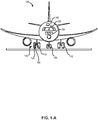
- FIG. 1-A illustrates an aircraft having multiple landing gear and brakes
- FIG. 1-B is a block diagram of a brake control unit of the aircraft of FIG. 1-A ;
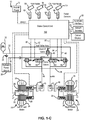
- FIG. 1-C is a functional diagram of a braking system of the aircraft of FIG. 1-A , having dump valves in the brake control module for rapid locked wheel control;
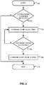
- FIG. 2 is a flowchart of a method of locked wheel brake control.
- a brake control system includes a dump valve for rapid release, or "dumping," of hydraulic pressure in response to a wheel skid condition being detected.
- the dump valve provides a relatively smooth path through which hydraulic pressure is released from the hydraulic lines, bypassing the servo valve.
- a brake control system as provided herein may provide rapid locked wheel response.
- an aircraft 100 includes multiple landing gear systems, including a first landing gear 110, second landing gear 120, and third landing gear 130.
- the first landing gear 110, second landing gear 120, and third landing gear 130 each include one or more wheel assemblies.
- the third landing gear 130 includes an inner wheel assembly 132 and an outer wheel assembly 134.
- the first landing gear 110, second landing gear 120, and third landing gear 130 support the aircraft 100 when the aircraft 100 is not flying, thereby allowing the aircraft 100 to take off, land, and taxi without damaging the aircraft 100.
- the second landing gear 120 is also a nose landing gear for the aircraft 100, and oftentimes, one or more of the first landing gear 110, second landing gear 120, and third landing gear 130 are operationally retractable into the aircraft 100 when the aircraft 100 is in flight and/or airborne.
- the aircraft 100 further includes an avionics unit 140, which includes one or more controllers (e.g., processors) and one or more tangible, non-transitory memories capable of implementing digital or programmatic logic.
- the one or more controllers are one or more of a general purpose processor, digital signal processor (DSP), application specific integrated circuit (ASIC), field programmable gate array (FPGA), or other programmable logic device, discrete gate, transistor logic, or discrete hardware components, or any various combinations thereof or the like.
- the avionics unit 140 controls, at least various parts of, the flight of, and operation of various components of, the aircraft 100.
- the avionics unit 140 controls various parameters of flight, such as an air traffic management systems, auto-pilot systems, auto-thrust systems, crew alerting systems, electrical systems, electronic checklist systems, electronic flight bag systems, engine systems flight control systems, environmental systems, hydraulics systems, lighting systems, pneumatics systems, traffic avoidance systems, trim systems, and the like.
- flight such as an air traffic management systems, auto-pilot systems, auto-thrust systems, crew alerting systems, electrical systems, electronic checklist systems, electronic flight bag systems, engine systems flight control systems, environmental systems, hydraulics systems, lighting systems, pneumatics systems, traffic avoidance systems, trim systems, and the like.
- the aircraft 100 further includes a brake control unit (BCU) 150.
- the BCU 150 includes one or more controllers 154 (e.g., processors) and one or more tangible, non-transitory memories 156 capable of implementing digital or programmatic logic.
- the one or more controllers 154 are one or more of a general purpose processor, DSP, ASIC, FPGA, or other programmable logic device, discrete gate, transistor logic, or discrete hardware components, or any various combinations thereof or the like, and the one or more memories 156 store instructions that are implemented by the one or more controllers 154 for performing various functions, such as monitoring a health status of a servo valve, as will be discussed herein.
- the BCU 150 controls, at least various parts of, the braking of the aircraft 100.
- the BCU 150 controls various parameters of braking, such as manual brake control, automatic brake control, antiskid braking, locked wheel protection, touchdown protection, park capability, gear retraction braking, and the like.
- the aircraft 100 further includes one or more brakes coupled to each wheel assembly.
- a brake 160 is coupled to the outer wheel assembly 134 of the third landing gear 130 of the aircraft 100.
- the brake 160 applies a braking force to the outer wheel assembly 134 upon receiving a brake command, such as from the BCU 150.
- the outer wheel assembly 134 of the third landing gear 130 of the aircraft 100 comprises any number of wheels.
- the braking system 10 includes the brake control unit (BCU) 150 of FIGS. 1-A and 1-B , which is programmed to control some of the various braking functions described herein.
- the braking system 10 enables the aircraft 100 to brake, thereby slowing aircraft 100 when on the ground.
- the braking system 10 may also be used in connection with other types of vehicles and other without departing from the scope of the inventive arrangements.
- the braking system generally includes, inter alia, a hydraulic power source 30 acting through i) a left wheel servo valve 42l to apply hydraulic pressure through a left hydraulic line 44l and shuttle valve 70 to apply a braking force to actuators 28 of a left wheel/brake assembly 22l; and ii) a right wheel servo valve 42r to apply hydraulic pressure through a right hydraulic line 44r and shuttle valve 70 to apply a braking force to actuators 28 of a right wheel/brake assembly 22r.
- First pressure sensors 48 may be intermediate, and in fluid communication with, the actuators 28 and shuttle valves 70 of the left wheel/brake assembly 22l and right wheel/brake assembly 22r.
- the shuttle valves 70, first pressure sensors 48, and actuators 28 may be common to both a primary braking system and a non-primary braking system of the braking system 10 of the aircraft 100.
- the BCU 150 receives brake command signals from a left pilot brake pedal 14l and a right pilot brake pedal 14r and/or a left co-pilot brake pedal 16l and a right co-pilot brake pedal 16r.
- the brake command signals from the left pilot brake pedal 14l and the right pilot brake pedal 14r and/or the left co-pilot brake pedal 16l and the right co-pilot brake pedal 16r are indicative of a desired amount of braking.
- the BCU 150 receives control signals from an auto-brake interface 18 for performing conventional auto-brake and rejected take-off (RTO) braking functions.
- the BCU 150 also receives a series of discrete control signals associated with the aircraft 100, generally represented as 20, for providing braking control thereof.
- the BCU 150 controls braking of the left wheel/brake assembly 22l and the right wheel/brake assembly 22r, as noted above.
- the left wheel/brake assembly 22l includes one or more wheels 24 and brake stacks 26.
- a plurality of actuators 28 are provided for exerting braking forces on the brake stacks 26 in order to brake the wheels 24.
- the right wheel/brake assembly 22r has a similar, mirrored configuration.
- Both the left wheel/brake assembly 22l and the right wheel/brake assembly 22r also include, in various embodiments, wheel speed sensors 27 that provide wheel speed information to the BCU 150 for carrying out brake control operations.
- a hydraulic power source 30 serves as a primary brake power supply within the braking system 10.
- a primary hydraulic line 32 from the hydraulic power source 30 includes a check valve 34 and an accumulator 36.
- the primary hydraulic line 32 is input into a brake control module (BCM) 38 included within the braking system 10.
- the BCM 38 includes a shutoff valve 40 through which the primary hydraulic line 32 supplies hydraulic fluid to the left wheel servo valve 42l and the right wheel servo valve 42r.
- BCM may be a dual valve assembly.
- hydraulic fluid from the left wheel servo valve 42l and the right wheel servo valve 42r is respectively provided through a left hydraulic line 44l and a right hydraulic line 44r to apply the braking force to the wheels 24 during a braking operation.
- a return line 47 is provided from the left wheel servo valve 42l and the right wheel servo valve 42r back to the hydraulic power source 30.
- hydraulic fluid pressure through the left hydraulic line 44l and the right hydraulic line 44r respectively passes to the corresponding actuators 28 via one or more of the corresponding shuttle valves 70.
- the shutoff valve 40 is open to the left hydraulic line 44l and the right hydraulic line 44r, and the BCU 150 controls the amount of hydraulic pressure that is delivered to the wheels 24 respectively via the left wheel servo valve 42l and the right wheel servo valve 42r acting through the corresponding left hydraulic line 44l and right hydraulic line 44r.
- the shutoff valve 40, the left wheel servo valve 42l, and the right wheel servo valve 42r are coil valves.
- the shutoff valve 40 receives a shutoff valve control signal on a bus 50 from the BCU 150.
- the left wheel servo valve 42l may receive a servo valve control signal on a bus 52 from the BCU 150.
- the right wheel servo valve 42r may receive a servo valve control signal on a bus 54 from the BCU 150.
- the left pilot brake pedal 14l may have a transducer 60 associated therewith.
- the transducer 60 may provide a brake command signal to the BCU 150 that is indicative of a degree of travel of the left pilot brake pedal 14l, and thus the amount of desired braking by the left wheel/brake assembly 22l.
- the remaining right pilot brake pedal 14r, the left co-pilot brake pedal 16l, and the right co-pilot brake pedal 16r each may have corresponding transducers respectively serving the BCU 150, including as follows: the right pilot brake pedal 14r includes transducer 62 serving the BCU 150; the left co-pilot brake pedal 16l includes transducer 64 serving the BCU 150; and the right co-pilot brake pedal 16r includes transducer 66 serving the BCU 150.
- the transducers may be collectively referred to herein as the transducers 60, 62, 64, 66.
- the transducers 60, 62, 64, 66 for respectively detecting the degree of movement of the left pilot brake pedal 14l and the right pilot brake pedal 14r and/or the left co-pilot brake pedal 16l and the right co-pilot brake pedal 16r are each linear variable differential transformers (LVDTs).
- LVDTs linear variable differential transformers
- the braking system 10 includes first pressure sensors 48 for monitoring the hydraulic pressure in the left hydraulic line 44l and the right hydraulic line 44r and providing such information back to the BCU 150.
- power to the BCU 150 is provided from an aircraft power source 72, such as a DC power source within the aircraft 100. In various embodiments, power is transmitted from the aircraft power source 72 to the BCU 150.
- the braking system 10 further includes an output device and/or output display 74 coupled to the BCU 150.
- the output device and/or output display 74 is configured to communicate information to the pilot, co-pilot, and/or maintenance crew relating to the braking operations.
- the output device and/or output display 74 includes a display, a speaker, a network access device, and/or the like that sends a message to a remote terminal, or the like.
- the BCU 150 controls the output device and/or display 74 to output the health status of the braking system 10, including the various components thereof.
- the braking system 10 may be activated by the left pilot brake pedal 14l, the right pilot brake pedal 14r, the left co-pilot brake pedal 16l, and the right co-pilot brake pedal 16r respectively acting through the shutoff valve 40, the left wheel servo valve 42l, the right wheel servo valve 42r, the left hydraulic line 44l, and the right hydraulic line 44r.
- the braking system 10 utilizes the shutoff valve 40 in-line with the left wheel servo valve 42l and the right wheel servo valve 42r to provide a level of redundancy that ensures a single valve failure cannot cause inadvertent braking.
- the shutoff valve 40 In order for the braking force to be applied by the braking system 10 to the left wheel/brake assembly 22l and the right wheel/brake assembly 22r, the shutoff valve 40 must be open along with at least one of the left wheel servo valve 42l and the right wheel servo valve 42r.
- each of the valves may contain dual control coils with one coil for different dedicated channels in the BCU 150, in accordance with various embodiments.
- the BCU 150 utilizes outputs from the transducers 60, 62, 64, 66 to measure the degree to which each respective left pilot brake pedal 14l, right pilot brake pedal 14r, left co-pilot brake pedal 16l, and right co-pilot brake pedal 16r is depressed. And although one transducer is shown for each of the left pilot brake pedal 14l, the right pilot brake pedal 14r, the left co-pilot brake pedal 16l, and the right co-pilot brake pedal 16r, any number of transducers may be used, for example for redundancy purposes, in various embodiments. In various embodiments, the transducers 60, 62, 64, 66 provide inputs to the BCU 150.
- BCM 38 includes a left wheel dump valve 46l to dump hydraulic pressure from left hydraulic line 44l to prevent left wheel/brake assembly 22l from locking up while an aircraft is moving relative to the ground surface (i.e., to prevent "wheel skid”).
- BCM 38 includes a right wheel dump valve 46r to dump hydraulic pressure from right hydraulic line 44r for preventing wheel skid of right wheel/brake assembly 22r.
- dump valve 46l may be in fluid communication with left hydraulic line 44l and dump valve 46r may be in fluid communication with right hydraulic line 44r.
- dump valve 46l is connected in parallel with left wheel servo valve 42l between left hydraulic line 44l and return line 47.
- dump valve 46r is connected in parallel with right wheel servo valve 42r between right hydraulic line 44r and return line 47.
- the dump valve 46l and the dump valve 46r are coil valves.
- the dump valve 46l and the dump valve 46r may be moveable between either an open position and a closed position, whereas left wheel servo valve 42l and the right wheel servo valve 42r are modulated for providing precise control of pressure within left hydraulic line 44l and right hydraulic line 44r.
- dump valves 46l, 46r may provide rapid release of hydraulic pressure in left hydraulic line 44l and right hydraulic line 44r, respectively, due to the simple architecture of the dump valves 46l, 46r, whereas servo valves comprise relatively tortuous paths through which the hydraulic fluid must travel in order to escape left hydraulic line 44l and/or right hydraulic line 44r.
- dump valve 46l and dump valve 46r may comprise shut-off valves.
- dump valve 46l and dump valve 46r may be similar to shutoff valve 40 (e.g., a solenoid valve).
- dump valve 46l and dump valve 46r may be moved to an open position in response to receiving electrical current and may be moved to a closed position in response to not receiving any electrical current.
- Dump valve 46l and dump valve 46r may comprise "ON/OFF" valves - that is electromechanical valves configured to actuate only between either a fully open position or a fully closed position.
- dump valve 46l and dump valve 46r may be moveable between only two positions - open or closed.
- the left wheel dump valve 46l may receive a dump valve control signal on a bus 56 from the BCU 150.
- the right wheel dump valve 46r may receive a dump valve control signal on a bus 58 from the BCU 150.
- the BCU 150 may send the dump valve control signal to dump valve 46r, via bus 58, to open dump valve 46r, thereby removing hydraulic pressure from right hydraulic line 44r and reducing braking forces on the brake stack 26 of right wheel/brake assembly 22r.
- the BCU 150 may send the dump valve control signal to dump valve 46l, via bus 56, to open dump valve 461, thereby removing hydraulic pressure from left hydraulic line 44l and reducing braking forces on the brake stack 26 of left wheel/brake assembly 22l.
- a method of locked wheel brake control begins in a step 200, after which it is determined if a locked wheel condition is detected at a step 202. If a locked wheel condition is not detected at step 202, then the method ends at a step 210. In various embodiments, if a locked wheel condition is detected at step 202, then the method commands a dump valve open at a step 204. Thereafter, it is determined if the wheel speed has recovered at a step 206. If the wheel speed has not recovered in step 206, then the dump valve is commanded open at step 204. In various embodiments, if the wheel speed has recovered in step 206, then the method commands the dump valve closed at step 208, after which the method of FIG. 2 ends at step 210.
- step 202 may include determining, by BCU 150, whether a locked wheel condition is detected.
- the BCU may detect that the rotational velocity of left wheel/brake assembly 22l and/or the right wheel/brake assembly 22r is below a first pre-determined threshold value, via wheel speed sensors 27 for example, during a braking maneuver.
- Step 204 may include commanding, by BCU 150, dump valve 46l and/or dump valve 46r opened, in response to the locked wheel condition being detected.
- step 204 may include sending, by BCU 150, a dump valve control signal to dump valve 46l and/or dump valve 46r to actuate dump valve 46l and/or dump valve 46r to an open position, whereby hydraulic fluid may travel from the corresponding left hydraulic line 44l and/or right hydraulic line 44r to hydraulic power source 30 via return line 47.
- Step 206 may include determining, by BCU 150 if the rotational velocity of left wheel/brake assembly 22l and/or the right wheel/brake assembly 22r has recovered from a locked wheel condition. For example, step 206 may include determining that the rotational velocity of left wheel/brake assembly 22l and/or the right wheel/brake assembly 22r is greater than a second pre-determined threshold value.
- Step 208 may include commanding, by BCU 150, dump valve 461 and/or dump valve 46r closed, in response to the rotational velocity of left wheel/brake assembly 22l and/or the right wheel/brake assembly 22r recovering, during a braking maneuver.
- step 208 may include ceasing to send, by BCU 150, the dump valve control signal to dump valve 46l and/or dump valve 46r to actuate dump valve 46l and/or dump valve 46r to a closed position.
- any of the method or process descriptions may be executed in any order and are not necessarily limited to the order presented.
- any reference to singular includes plural embodiments, and any reference to more than one component or step may include a singular embodiment or step.
- Elements and steps in the figures are illustrated for simplicity and clarity and have not necessarily been rendered according to any particular sequence. For example, steps that may be performed concurrently or in different order are only illustrated in the figures to help to improve understanding of embodiments of the present, representative disclosure.
- Any reference to attached, fixed, connected, or the like may include permanent, removable, temporary, partial, full and/or any other possible attachment option. Additionally, any reference to without contact (or similar phrases) may also include reduced contact or minimal contact. Surface shading lines may be used throughout the figures to denote different parts or areas, but not necessarily to denote the same or different materials. In some cases, reference coordinates may be specific to each figure.
- references to "one embodiment,” “an embodiment,” “various embodiments,” etc. indicate that the embodiment described may include a particular feature, structure, or characteristic, but every embodiment may not necessarily include the particular feature, structure, or characteristic. Moreover, such phrases are not necessarily referring to the same embodiment. Further, when a particular feature, structure, or characteristic is described in connection with an embodiment, it is submitted that it is within the knowledge of one skilled in the art to affect such feature, structure, or characteristic in connection with other embodiments, whether or not explicitly described. After reading the description, it will be apparent to one skilled in the relevant art(s) how to implement the disclosure in alternative embodiments.
Landscapes
- Engineering & Computer Science (AREA)
- Mechanical Engineering (AREA)
- Aviation & Aerospace Engineering (AREA)
- Transportation (AREA)
- Physics & Mathematics (AREA)
- Fluid Mechanics (AREA)
- Regulating Braking Force (AREA)
Abstract
Description
- In general, the arrangements disclosed herein relate to braking systems and methods. More specifically, they relate to improvements for braking systems and methods suitable for use in aircraft.
- Aircraft include many parts that are suitable for monitoring and periodic replacement. For example, many aircraft braking systems include one or more servo valves suited for converting variations in an electrical signal into variations in how much hydraulic fluid is transmitted to a brake actuator. Such servo valves can be used to control powerful hydraulic cylinders with small electrical signals. They can provide precise levels of control over force, position, pressure, and velocity, etc., such as by electrically coupling to a power source to apply a desired amount of electrical current to the servo valve in order to actuate a poppet internal to the servo valve and suitably open or close the servo valve to thus control the amount of hydraulic pressure output by the servo valve. Sensors in communication with servo valves can monitor the amount of electrical current (electrical signal) input into the servo valve and the corresponding hydraulic pressure output from the servo valve (hydraulic pressure signal).
- Typically, transport aircraft utilize antiskid systems to control wheel skidding during braking. Uncontrolled skids, or "lockups" may result in greatly reduced braking effectiveness, loss of tire cornering ("road-holding") capability, and tire flatspots or blowouts. During most braking conditions, this skid protection is achieved by circuits or mechanisms which release braking pressure, via the servo valve(s), to a single (or group of) wheel(s) upon detection of a sudden decrease in wheel speed. Servo valves comprise relatively tortuous paths through which the hydraulic fluid travels in order to release the braking pressure.
- A brake control system is disclosed, comprising a non-transitory memory configured to store instructions, and a controller in electronic communication with the memory, the controller configured to control a servo valve, determine whether a locked wheel condition is detected, command a dump valve to open in response to the locked wheel condition being detected to release the hydraulic fluid from the hydraulic line, determine whether a wheel speed has recovered, and command the dump valve closed in response to the wheel speed being recovered.
- In various embodiments, the brake control system further comprises a brake control module, comprising a shutoff valve configured to receive a hydraulic fluid, the servo valve configured to receive the hydraulic fluid from the shutoff valve and configured to provide the hydraulic fluid to apply braking force to a wheel via a hydraulic line, and the dump valve, wherein the dump valve is in fluid communication with the hydraulic line.
- In various embodiments, the controller determines whether the locked wheel condition is detected by determining whether a rotational velocity of the wheel has decreased below a first pre-determined threshold value.
- In various embodiments, the controller determines whether the wheel speed has recovered by determining whether the rotational velocity of the wheel has increased above a second pre-determined threshold value.
- In various embodiments, the controller commands the dump valve open by sending a dump valve control signal to the dump valve.
- In various embodiments, the controller commands the dump valve closed by ceasing to send the dump valve control signal to the dump valve.
- In various embodiments, the dump valve is connected in parallel with the servo valve.
- In various embodiments, the dump valve comprises a left wheel dump valve, the servo valve comprises a left wheel servo valve, and the brake control module further comprises a right wheel dump valve and a right wheel servo valve, wherein the right wheel dump valve is connected in parallel with the right wheel servo valve.
- A brake control system is disclosed herein, comprising a brake control module, comprising a shutoff valve configured to receive a hydraulic fluid, a servo valve configured to receive the hydraulic fluid from the shutoff valve and configured to provide the hydraulic fluid to apply braking force to a wheel via a hydraulic line, and a dump valve in fluid communication with the hydraulic line.
- In various embodiments, the dump valve is connected in parallel with the servo valve.
- In various embodiments, dump valve and the servo valve are in fluid communication with a return line, whereby hydraulic pressure in the hydraulic line may be released.
- In various embodiments, the dump valve is a left wheel dump valve, the servo valve is a left wheel servo valve, the wheel is a left wheel, and the brake control module further comprises a right wheel dump valve and a right wheel servo valve, wherein the left wheel dump valve is connected in parallel with the right wheel servo valve and the right wheel dump valve is connected in parallel with the right wheel servo valve.
- In various embodiments, the left wheel dump valve is configured to be commanded open in response to a rotational velocity of the left wheel decreasing below a first predetermined threshold value during a braking maneuver.
- In various embodiments, the left wheel dump valve is configured to release the hydraulic fluid from the hydraulic line in response to being opened to decrease the braking force to the left wheel.
- In various embodiments, the left wheel dump valve is configured to be commanded closed in response to the rotational velocity of the left wheel increasing above a second predetermined threshold value during the braking maneuver.
- A method for locked wheel brake control is disclosed, comprising determining whether a locked wheel condition is detected, commanding a dump valve open in response to the locked wheel condition being detected to release a hydraulic fluid from a hydraulic line, determining whether a wheel speed has recovered, and commanding the dump valve closed in response to the wheel speed being recovered.
- In various embodiments, the locked wheel condition is detected by determining whether a rotational velocity of a wheel has decreased below a first pre-determined threshold value.
- In various embodiments, determining whether the wheel speed has recovered includes determining whether the rotational velocity of the wheel has increased above a second pre-determined threshold value.
- In various embodiments, the dump valve is commanded open by sending a dump valve control signal to the dump valve.
- In various embodiments, the dump valve is commanded closed by ceasing to send the dump valve control signal to the dump valve.
- The accompanying drawings illustrate various embodiments employing the principles described herein and are a part of this specification. The illustrated embodiments are meant for description only, and they do not limit the scope of the claims, and in which:
- In various embodiments,
FIG. 1-A illustrates an aircraft having multiple landing gear and brakes; - In various embodiments,
FIG. 1-B is a block diagram of a brake control unit of the aircraft ofFIG. 1-A ; - In various embodiments,
FIG. 1-C is a functional diagram of a braking system of the aircraft ofFIG. 1-A , having dump valves in the brake control module for rapid locked wheel control; - In various embodiments,
FIG. 2 is a flowchart of a method of locked wheel brake control. - The detailed description of exemplary embodiments herein makes reference to the accompanying drawings, which show exemplary embodiments by way of illustration. While these exemplary embodiments are described in sufficient detail to enable those skilled in the art to practice the disclosure, it should be understood that other embodiments may be realized and that logical changes and adaptations in design and construction may be made in accordance with this disclosure and the teachings herein described without departing from the scope of the invention as defined by the claims. Thus, the detailed description herein is presented for purposes of illustration only and not of limitation.
- Provided herein, according to various embodiments, are systems and methods for brake control with antiskid protection, such as within a braking system of an aircraft. While numerous details are included herein pertaining to aircraft components, such as brake components, the systems and methods disclosed herein can be applied to other systems with other servo valves and the like. A brake control system, as disclosed herein, includes a dump valve for rapid release, or "dumping," of hydraulic pressure in response to a wheel skid condition being detected. The dump valve provides a relatively smooth path through which hydraulic pressure is released from the hydraulic lines, bypassing the servo valve. A brake control system as provided herein may provide rapid locked wheel response.
- Referring now to
FIG. 1-A , anaircraft 100 includes multiple landing gear systems, including afirst landing gear 110,second landing gear 120, andthird landing gear 130. Thefirst landing gear 110,second landing gear 120, andthird landing gear 130 each include one or more wheel assemblies. For example, thethird landing gear 130 includes aninner wheel assembly 132 and anouter wheel assembly 134. Thefirst landing gear 110,second landing gear 120, andthird landing gear 130 support theaircraft 100 when theaircraft 100 is not flying, thereby allowing theaircraft 100 to take off, land, and taxi without damaging theaircraft 100. In various embodiments, thesecond landing gear 120 is also a nose landing gear for theaircraft 100, and oftentimes, one or more of thefirst landing gear 110,second landing gear 120, andthird landing gear 130 are operationally retractable into theaircraft 100 when theaircraft 100 is in flight and/or airborne. - In various embodiments, the
aircraft 100 further includes anavionics unit 140, which includes one or more controllers (e.g., processors) and one or more tangible, non-transitory memories capable of implementing digital or programmatic logic. In various embodiments, for example, the one or more controllers are one or more of a general purpose processor, digital signal processor (DSP), application specific integrated circuit (ASIC), field programmable gate array (FPGA), or other programmable logic device, discrete gate, transistor logic, or discrete hardware components, or any various combinations thereof or the like. In various embodiments, theavionics unit 140 controls, at least various parts of, the flight of, and operation of various components of, theaircraft 100. For example, theavionics unit 140 controls various parameters of flight, such as an air traffic management systems, auto-pilot systems, auto-thrust systems, crew alerting systems, electrical systems, electronic checklist systems, electronic flight bag systems, engine systems flight control systems, environmental systems, hydraulics systems, lighting systems, pneumatics systems, traffic avoidance systems, trim systems, and the like. - In various embodiments, the
aircraft 100 further includes a brake control unit (BCU) 150. With brief reference now toFIG. 1-B , the BCU 150 includes one or more controllers 154 (e.g., processors) and one or more tangible,non-transitory memories 156 capable of implementing digital or programmatic logic. In various embodiments, for example, the one ormore controllers 154 are one or more of a general purpose processor, DSP, ASIC, FPGA, or other programmable logic device, discrete gate, transistor logic, or discrete hardware components, or any various combinations thereof or the like, and the one ormore memories 156 store instructions that are implemented by the one ormore controllers 154 for performing various functions, such as monitoring a health status of a servo valve, as will be discussed herein. In various embodiments, the BCU 150 controls, at least various parts of, the braking of theaircraft 100. For example, the BCU 150 controls various parameters of braking, such as manual brake control, automatic brake control, antiskid braking, locked wheel protection, touchdown protection, park capability, gear retraction braking, and the like. - Referring again more particularly to
FIG. 1-A , theaircraft 100 further includes one or more brakes coupled to each wheel assembly. For example, abrake 160 is coupled to theouter wheel assembly 134 of thethird landing gear 130 of theaircraft 100. In operation, thebrake 160 applies a braking force to theouter wheel assembly 134 upon receiving a brake command, such as from theBCU 150. In various embodiments, theouter wheel assembly 134 of thethird landing gear 130 of theaircraft 100 comprises any number of wheels. - Referring now also to
FIG. 1-C , including with continued reference toFIGS. 1-A and1-B as well, a closed-loop braking system 10 is shown in accordance with an embodiment of the inventive arrangements. Thebraking system 10 includes the brake control unit (BCU) 150 ofFIGS. 1-A and1-B , which is programmed to control some of the various braking functions described herein. In various embodiments, thebraking system 10 enables theaircraft 100 to brake, thereby slowingaircraft 100 when on the ground. However, it will be appreciated that thebraking system 10 may also be used in connection with other types of vehicles and other without departing from the scope of the inventive arrangements. - As described herein, the braking system generally includes, inter alia, a
hydraulic power source 30 acting through i) a left wheel servo valve 42l to apply hydraulic pressure through a left hydraulic line 44l andshuttle valve 70 to apply a braking force to actuators 28 of a left wheel/brake assembly 22l; and ii) a rightwheel servo valve 42r to apply hydraulic pressure through a righthydraulic line 44r andshuttle valve 70 to apply a braking force to actuators 28 of a right wheel/brake assembly 22r.First pressure sensors 48 may be intermediate, and in fluid communication with, theactuators 28 andshuttle valves 70 of the left wheel/brake assembly 22l and right wheel/brake assembly 22r. - In various embodiments, the
shuttle valves 70,first pressure sensors 48, andactuators 28 may be common to both a primary braking system and a non-primary braking system of thebraking system 10 of theaircraft 100. - In various embodiments of the braking system, the
BCU 150 receives brake command signals from a left pilot brake pedal 14l and a rightpilot brake pedal 14r and/or a left co-pilot brake pedal 16l and a rightco-pilot brake pedal 16r. The brake command signals from the left pilot brake pedal 14l and the rightpilot brake pedal 14r and/or the left co-pilot brake pedal 16l and the rightco-pilot brake pedal 16r are indicative of a desired amount of braking. In addition, theBCU 150 receives control signals from an auto-brake interface 18 for performing conventional auto-brake and rejected take-off (RTO) braking functions. TheBCU 150 also receives a series of discrete control signals associated with theaircraft 100, generally represented as 20, for providing braking control thereof. - In various embodiments, the
BCU 150 controls braking of the left wheel/brake assembly 22l and the right wheel/brake assembly 22r, as noted above. The left wheel/brake assembly 22l includes one ormore wheels 24 and brake stacks 26. A plurality ofactuators 28 are provided for exerting braking forces on the brake stacks 26 in order to brake thewheels 24. The right wheel/brake assembly 22r has a similar, mirrored configuration. Both the left wheel/brake assembly 22l and the right wheel/brake assembly 22r also include, in various embodiments,wheel speed sensors 27 that provide wheel speed information to theBCU 150 for carrying out brake control operations. - In various embodiments of the braking system, a
hydraulic power source 30 serves as a primary brake power supply within thebraking system 10. In various embodiments, a primaryhydraulic line 32 from thehydraulic power source 30 includes acheck valve 34 and anaccumulator 36. In various embodiments, the primaryhydraulic line 32 is input into a brake control module (BCM) 38 included within thebraking system 10. TheBCM 38 includes ashutoff valve 40 through which the primaryhydraulic line 32 supplies hydraulic fluid to the left wheel servo valve 42l and the rightwheel servo valve 42r. In this regard, BCM may be a dual valve assembly. In various embodiments, hydraulic fluid from the left wheel servo valve 42l and the rightwheel servo valve 42r is respectively provided through a left hydraulic line 44l and a righthydraulic line 44r to apply the braking force to thewheels 24 during a braking operation. In various embodiments, areturn line 47 is provided from the left wheel servo valve 42l and the rightwheel servo valve 42r back to thehydraulic power source 30. - During primary braking operations, hydraulic fluid pressure through the left hydraulic line 44l and the right
hydraulic line 44r respectively passes to the correspondingactuators 28 via one or more of the correspondingshuttle valves 70. Thus, if thebraking system 10 is functioning in the primary braking mode, theshutoff valve 40 is open to the left hydraulic line 44l and the righthydraulic line 44r, and theBCU 150 controls the amount of hydraulic pressure that is delivered to thewheels 24 respectively via the left wheel servo valve 42l and the rightwheel servo valve 42r acting through the corresponding left hydraulic line 44l and righthydraulic line 44r. - In various embodiments, the
shutoff valve 40, the left wheel servo valve 42l, and the rightwheel servo valve 42r are coil valves. In various embodiments, theshutoff valve 40 receives a shutoff valve control signal on abus 50 from theBCU 150. Similarly, the left wheel servo valve 42l may receive a servo valve control signal on abus 52 from theBCU 150. Likewise, the rightwheel servo valve 42r may receive a servo valve control signal on abus 54 from theBCU 150. - In various embodiments, the left pilot brake pedal 14l may have a
transducer 60 associated therewith. Thetransducer 60 may provide a brake command signal to theBCU 150 that is indicative of a degree of travel of the left pilot brake pedal 14l, and thus the amount of desired braking by the left wheel/brake assembly 22l. - Similarly, the remaining right
pilot brake pedal 14r, the left co-pilot brake pedal 16l, and the rightco-pilot brake pedal 16r each may have corresponding transducers respectively serving theBCU 150, including as follows: the rightpilot brake pedal 14r includestransducer 62 serving theBCU 150; the left co-pilot brake pedal 16l includes transducer 64 serving theBCU 150; and the rightco-pilot brake pedal 16r includestransducer 66 serving theBCU 150. The transducers may be collectively referred to herein as thetransducers transducers pilot brake pedal 14r and/or the left co-pilot brake pedal 16l and the rightco-pilot brake pedal 16r are each linear variable differential transformers (LVDTs). In various embodiments, it will be appreciated that other transducers may be used without departing from the scope of the inventive arrangements. - In various embodiments, the
braking system 10 includesfirst pressure sensors 48 for monitoring the hydraulic pressure in the left hydraulic line 44l and the righthydraulic line 44r and providing such information back to theBCU 150. In addition, power to theBCU 150 is provided from anaircraft power source 72, such as a DC power source within theaircraft 100. In various embodiments, power is transmitted from theaircraft power source 72 to theBCU 150. - In various embodiments, the
braking system 10 further includes an output device and/oroutput display 74 coupled to theBCU 150. The output device and/oroutput display 74 is configured to communicate information to the pilot, co-pilot, and/or maintenance crew relating to the braking operations. For example, in various embodiments, the output device and/oroutput display 74 includes a display, a speaker, a network access device, and/or the like that sends a message to a remote terminal, or the like. In various embodiments, theBCU 150 controls the output device and/ordisplay 74 to output the health status of thebraking system 10, including the various components thereof. - In various embodiments, the
braking system 10 may be activated by the left pilot brake pedal 14l, the rightpilot brake pedal 14r, the left co-pilot brake pedal 16l, and the rightco-pilot brake pedal 16r respectively acting through theshutoff valve 40, the left wheel servo valve 42l, the rightwheel servo valve 42r, the left hydraulic line 44l, and the righthydraulic line 44r. - The
braking system 10 utilizes theshutoff valve 40 in-line with the left wheel servo valve 42l and the rightwheel servo valve 42r to provide a level of redundancy that ensures a single valve failure cannot cause inadvertent braking. In order for the braking force to be applied by thebraking system 10 to the left wheel/brake assembly 22l and the right wheel/brake assembly 22r, theshutoff valve 40 must be open along with at least one of the left wheel servo valve 42l and the rightwheel servo valve 42r. To provide a redundancy so that the brakes can be operated when commanded, each of the valves (shutoff and servo) may contain dual control coils with one coil for different dedicated channels in theBCU 150, in accordance with various embodiments. - The
BCU 150 utilizes outputs from thetransducers pilot brake pedal 14r, left co-pilot brake pedal 16l, and rightco-pilot brake pedal 16r is depressed. And although one transducer is shown for each of the left pilot brake pedal 14l, the rightpilot brake pedal 14r, the left co-pilot brake pedal 16l, and the rightco-pilot brake pedal 16r, any number of transducers may be used, for example for redundancy purposes, in various embodiments. In various embodiments, thetransducers BCU 150. - In various embodiments,
BCM 38 includes a left wheel dump valve 46l to dump hydraulic pressure from left hydraulic line 44l to prevent left wheel/brake assembly 22l from locking up while an aircraft is moving relative to the ground surface (i.e., to prevent "wheel skid"). Likewise,BCM 38 includes a rightwheel dump valve 46r to dump hydraulic pressure from righthydraulic line 44r for preventing wheel skid of right wheel/brake assembly 22r. In this regard, dump valve 46l may be in fluid communication with left hydraulic line 44l and dumpvalve 46r may be in fluid communication with righthydraulic line 44r. In various embodiments, dump valve 46l is connected in parallel with left wheel servo valve 42l between left hydraulic line 44l and returnline 47. In various embodiments, dumpvalve 46r is connected in parallel with rightwheel servo valve 42r between righthydraulic line 44r and returnline 47. - In various embodiments, the dump valve 46l and the
dump valve 46r are coil valves. In contrast to the left wheel servo valve 42l and the rightwheel servo valve 42r, the dump valve 46l and thedump valve 46r may be moveable between either an open position and a closed position, whereas left wheel servo valve 42l and the rightwheel servo valve 42r are modulated for providing precise control of pressure within left hydraulic line 44l and righthydraulic line 44r. In contrast to left wheel servo valve 42l and the rightwheel servo valve 42r, dumpvalves 46l, 46r, may provide rapid release of hydraulic pressure in left hydraulic line 44l and righthydraulic line 44r, respectively, due to the simple architecture of thedump valves 46l, 46r, whereas servo valves comprise relatively tortuous paths through which the hydraulic fluid must travel in order to escape left hydraulic line 44l and/or righthydraulic line 44r. In this regard, dump valve 46l and dumpvalve 46r may comprise shut-off valves. In various embodiments, dump valve 46l and dumpvalve 46r may be similar to shutoff valve 40 (e.g., a solenoid valve). In this regard, dump valve 46l and dumpvalve 46r may be moved to an open position in response to receiving electrical current and may be moved to a closed position in response to not receiving any electrical current. Dump valve 46l and dumpvalve 46r may comprise "ON/OFF" valves - that is electromechanical valves configured to actuate only between either a fully open position or a fully closed position. In this regard, in accordance with various embodiments, dump valve 46l and dumpvalve 46r may be moveable between only two positions - open or closed. - In various embodiments, the left wheel dump valve 46l may receive a dump valve control signal on a
bus 56 from theBCU 150. Likewise, the rightwheel dump valve 46r may receive a dump valve control signal on abus 58 from theBCU 150. In response to theBCU 150 detecting a wheel skid condition in right wheel/brake assembly 22r, theBCU 150 may send the dump valve control signal to dumpvalve 46r, viabus 58, to opendump valve 46r, thereby removing hydraulic pressure from righthydraulic line 44r and reducing braking forces on thebrake stack 26 of right wheel/brake assembly 22r. Likewise, in response to theBCU 150 detecting a wheel skid condition in left wheel/brake assembly 22l, theBCU 150 may send the dump valve control signal to dump valve 46l, viabus 56, to opendump valve 461, thereby removing hydraulic pressure from left hydraulic line 44l and reducing braking forces on thebrake stack 26 of left wheel/brake assembly 22l. - Referring now to
FIG. 2 , a method of locked wheel brake control is provided. More specifically, the method begins in astep 200, after which it is determined if a locked wheel condition is detected at a step 202. If a locked wheel condition is not detected at step 202, then the method ends at astep 210. In various embodiments, if a locked wheel condition is detected at step 202, then the method commands a dump valve open at astep 204. Thereafter, it is determined if the wheel speed has recovered at astep 206. If the wheel speed has not recovered instep 206, then the dump valve is commanded open atstep 204. In various embodiments, if the wheel speed has recovered instep 206, then the method commands the dump valve closed atstep 208, after which the method ofFIG. 2 ends atstep 210. - With combined reference to
FIG. 1-C andFIG. 2 , step 202 may include determining, byBCU 150, whether a locked wheel condition is detected. For example, the BCU may detect that the rotational velocity of left wheel/brake assembly 22l and/or the right wheel/brake assembly 22r is below a first pre-determined threshold value, viawheel speed sensors 27 for example, during a braking maneuver. Step 204 may include commanding, byBCU 150, dump valve 46l and/or dumpvalve 46r opened, in response to the locked wheel condition being detected. For example, step 204 may include sending, byBCU 150, a dump valve control signal to dump valve 46l and/or dumpvalve 46r to actuate dump valve 46l and/or dumpvalve 46r to an open position, whereby hydraulic fluid may travel from the corresponding left hydraulic line 44l and/or righthydraulic line 44r tohydraulic power source 30 viareturn line 47. Step 206 may include determining, byBCU 150 if the rotational velocity of left wheel/brake assembly 22l and/or the right wheel/brake assembly 22r has recovered from a locked wheel condition. For example, step 206 may include determining that the rotational velocity of left wheel/brake assembly 22l and/or the right wheel/brake assembly 22r is greater than a second pre-determined threshold value. Step 208 may include commanding, byBCU 150,dump valve 461 and/or dumpvalve 46r closed, in response to the rotational velocity of left wheel/brake assembly 22l and/or the right wheel/brake assembly 22r recovering, during a braking maneuver. For example, step 208 may include ceasing to send, byBCU 150, the dump valve control signal to dump valve 46l and/or dumpvalve 46r to actuate dump valve 46l and/or dumpvalve 46r to a closed position. - Benefits, other advantages, and solutions to problems have been described herein with regard to specific embodiments. Furthermore, the connecting lines shown in the various figures contained herein are intended to represent exemplary functional relationships and/or physical couplings between the various elements. It should be noted that many alternative or additional functional relationships or physical connections may be present in a practical system. However, the benefits, advantages, solutions to problems, and any elements that may cause any benefit, advantage, or solution to occur or become more pronounced are not to be construed as critical, required, or essential features or elements of the disclosure.
- The scope of the disclosure is accordingly to be limited by nothing other than the appended claims, in which reference to an element in the singular is not intended to mean "one and only one" unless explicitly so stated, but rather "one or more." It is to be understood that unless specifically stated otherwise, references to "a," "an," and/or "the" may include one or more than one, and that reference to an item in the singular may also include the item in the plural. All ranges and ratio limits disclosed herein may be combined.
- Moreover, where a phrase similar to "at least one of A, B, and C" is used in the claims, it is intended that the phrase be interpreted to mean that A alone may be present in an embodiment, B alone may be present in an embodiment, C alone may be present in an embodiment, or that any combination of the elements A, B, and C may be present in a single embodiment; for example, A and B, A and C, B and C, or A and B and C. Different cross-hatching is used throughout the figures to denote different parts, but not necessarily to denote the same or different materials.
- The steps recited in any of the method or process descriptions may be executed in any order and are not necessarily limited to the order presented. Furthermore, any reference to singular includes plural embodiments, and any reference to more than one component or step may include a singular embodiment or step. Elements and steps in the figures are illustrated for simplicity and clarity and have not necessarily been rendered according to any particular sequence. For example, steps that may be performed concurrently or in different order are only illustrated in the figures to help to improve understanding of embodiments of the present, representative disclosure.
- Any reference to attached, fixed, connected, or the like may include permanent, removable, temporary, partial, full and/or any other possible attachment option. Additionally, any reference to without contact (or similar phrases) may also include reduced contact or minimal contact. Surface shading lines may be used throughout the figures to denote different parts or areas, but not necessarily to denote the same or different materials. In some cases, reference coordinates may be specific to each figure.
- Systems, methods, and apparatus are provided herein. In the detailed description herein, references to "one embodiment," "an embodiment," "various embodiments," etc., indicate that the embodiment described may include a particular feature, structure, or characteristic, but every embodiment may not necessarily include the particular feature, structure, or characteristic. Moreover, such phrases are not necessarily referring to the same embodiment. Further, when a particular feature, structure, or characteristic is described in connection with an embodiment, it is submitted that it is within the knowledge of one skilled in the art to affect such feature, structure, or characteristic in connection with other embodiments, whether or not explicitly described. After reading the description, it will be apparent to one skilled in the relevant art(s) how to implement the disclosure in alternative embodiments.
Claims (15)
- A brake control system, comprising:a non-transitory memory (156) configured to store instructions; anda controller (154) in electronic communication with the memory, the controller configured to:control a servo valve (42);determine whether a locked wheel condition is detected;command a dump valve (46) to open in response to the locked wheel condition being detected to release the hydraulic fluid from the hydraulic line;determine whether a wheel speed has recovered; andcommand the dump valve closed in response to the wheel speed being recovered.
- The brake control system of claim 1, further comprising a brake control module (38), comprising:a shutoff valve (40) configured to receive a hydraulic fluid;the servo valve configured to receive the hydraulic fluid from the shutoff valve and configured to provide the hydraulic fluid to apply braking force to a wheel via a hydraulic line; andthe dump valve, wherein the dump valve is in fluid communication with the hydraulic line.
- The brake control system of claim 2, wherein the controller determines whether the locked wheel condition is detected by determining whether a rotational velocity of the wheel has decreased below a first pre-determined threshold value, and preferably wherein the controller determines whether the wheel speed has recovered by determining whether the rotational velocity of the wheel has increased above a second pre-determined threshold value.
- The brake control system of claim 2 or 3, wherein the controller (154) commands the dump valve open by sending a dump valve control signal to the dump valve, and preferably wherein the controller commands the dump valve closed by ceasing to send the dump valve control signal to the dump valve.
- The brake control system of claim 2, 3 or 4, wherein the dump valve (46) is connected in parallel with the servo valve.
- The brake control system of claim 5, wherein:the dump valve comprises a left wheel dump valve (46l);the servo valve comprises a left wheel servo valve (42l); andthe brake control module further comprises:a right wheel dump valve (46r); anda right wheel servo valve (42r), wherein the right wheel dump valve is connected in parallel with the right wheel servo valve.
- A brake control system, comprising:
a brake control module (38), comprising:a shutoff valve (40) configured to receive a hydraulic fluid;a servo valve (42) configured to receive the hydraulic fluid from the shutoff valve and configured to provide the hydraulic fluid to apply braking force to a wheel via a hydraulic line; anda dump valve (46) in fluid communication with the hydraulic line. - The brake control system of claim 7, wherein the dump valve is connected in parallel with the servo valve, and preferably wherein dump valve and the servo valve are in fluid communication with a return line, whereby hydraulic pressure in the hydraulic line may be released.
- The brake control system of claim 7 or 8, wherein:the dump valve is a left wheel dump valve (46l);the servo valve is a left wheel servo valve (42l);the wheel is a left wheel; andthe brake control module further comprises:a right wheel dump valve (46r); anda right wheel servo valve (42r);wherein the left wheel dump valve is connected in parallel with the left wheel servo valve and the right wheel dump valve is connected in parallel with the right wheel servo valve.
- The brake control system of claim 9, wherein the left wheel dump valve is configured to be commanded open in response to a rotational velocity of the left wheel decreasing below a first predetermined threshold value during a braking maneuver, and preferably wherein the left wheel dump valve is configured to release the hydraulic fluid from the hydraulic line in response to being opened to decrease the braking force to the left wheel, and preferably wherein the left wheel dump valve is configured to be commanded closed in response to the rotational velocity of the left wheel increasing above a second predetermined threshold value during the braking maneuver.
- A method for locked wheel brake control, comprising:determining whether a locked wheel condition is detected;commanding a dump valve open in response to the locked wheel condition being detected to release a hydraulic fluid from a hydraulic line;determining whether a wheel speed has recovered; andcommanding the dump valve closed in response to the wheel speed being recovered.
- The method of claim 11, wherein the locked wheel condition is detected by determining whether a rotational velocity of a wheel has decreased below a first pre-determined threshold value.
- The method of claim 12, wherein determining whether the wheel speed has recovered includes determining whether the rotational velocity of the wheel has increased above a second pre-determined threshold value.
- The method of claim 11, 12 or 13, wherein the dump valve is commanded open by sending a dump valve control signal to the dump valve.
- The method of claim 14, wherein the dump valve is commanded closed by ceasing to send the dump valve control signal to the dump valve.
Applications Claiming Priority (1)
| Application Number | Priority Date | Filing Date | Title |
|---|---|---|---|
| US16/033,967 US10703464B2 (en) | 2018-07-12 | 2018-07-12 | Architecture for locked wheel and antiskid performance |
Publications (2)
| Publication Number | Publication Date |
|---|---|
| EP3594076A1 true EP3594076A1 (en) | 2020-01-15 |
| EP3594076B1 EP3594076B1 (en) | 2023-11-29 |
Family
ID=67437657
Family Applications (1)
| Application Number | Title | Priority Date | Filing Date |
|---|---|---|---|
| EP19185587.3A Active EP3594076B1 (en) | 2018-07-12 | 2019-07-10 | Architecture for locked wheel and antiskid performance |
Country Status (2)
| Country | Link |
|---|---|
| US (1) | US10703464B2 (en) |
| EP (1) | EP3594076B1 (en) |
Cited By (4)
| Publication number | Priority date | Publication date | Assignee | Title |
|---|---|---|---|---|
| EP3835149A1 (en) * | 2019-12-13 | 2021-06-16 | Goodrich Corporation | Aircraft brake system |
| CN113734123A (en) * | 2021-09-22 | 2021-12-03 | 一汽解放汽车有限公司 | Automatic driving hydraulic braking system |
| CN113799975A (en) * | 2021-08-18 | 2021-12-17 | 西安航空制动科技有限公司 | Aircraft brake controller based on FPGA |
| EP4008593A1 (en) * | 2020-12-02 | 2022-06-08 | Goodrich Corporation | Health monitoring systems and methods for servo valves |
Families Citing this family (8)
| Publication number | Priority date | Publication date | Assignee | Title |
|---|---|---|---|---|
| US11080660B2 (en) * | 2017-03-20 | 2021-08-03 | The Boeing Company | Data-driven unsupervised algorithm for analyzing sensor data to detect abnormal valve operation |
| GB2563675A (en) * | 2017-06-23 | 2018-12-26 | Airbus Operations Ltd | Aircraft hydraulics |
| US11505167B2 (en) * | 2020-01-06 | 2022-11-22 | The Boeing Company | Aircraft brake control systems |
| CN113619776B (en) * | 2021-08-10 | 2024-04-26 | 哈尔滨理工大学 | Aircraft braking electrohydraulic servo system with high response and high stability characteristics |
| US12060052B2 (en) * | 2021-09-10 | 2024-08-13 | Goodrich Corporation | Valve assembly for brake control system |
| US12291183B2 (en) * | 2022-10-26 | 2025-05-06 | Goodrich Corporation | Advanced locked wheel protection functionality |
| FR3153596A1 (en) * | 2023-09-28 | 2025-04-04 | Safran Landing Systems | Simplified aircraft braking system |
| CN119611749B (en) * | 2025-01-02 | 2025-10-21 | 中国航空工业集团公司西安飞机设计研究所 | Method and system for rapid pressure relief of aircraft wheel brakes |
Citations (3)
| Publication number | Priority date | Publication date | Assignee | Title |
|---|---|---|---|---|
| US5775785A (en) * | 1994-03-25 | 1998-07-07 | Lucas Industries Plc | Anti-lock braking system having pulsed pressure re-application |
| US20040239173A1 (en) * | 2003-05-30 | 2004-12-02 | Williams Aaron Charles | Redundant architecture for brake-by-wire system |
| CN105000006A (en) * | 2015-02-02 | 2015-10-28 | 孙宏斌 | ABS (Anti-lock Braking System) braking method and device, ABS control method for electric vehicle and vehicle stabilizing method |
Family Cites Families (16)
| Publication number | Priority date | Publication date | Assignee | Title |
|---|---|---|---|---|
| US3847445A (en) * | 1973-11-12 | 1974-11-12 | Boeing Co | Aircraft automatic braking system having auto-brake control logic |
| US4536041A (en) | 1983-05-10 | 1985-08-20 | Znameni Politekhnichesky Institut | Anti-lock brake system of a motor vehicle |
| US4828335A (en) | 1985-08-09 | 1989-05-09 | Kelsey-Hayes Company | Control valve for vehicle anti-lock brake system |
| JPH06127361A (en) | 1992-10-14 | 1994-05-10 | Tokico Ltd | Brake fluid pressure control device |
| FR2816583B1 (en) | 2000-11-10 | 2003-02-21 | Messier Bugatti | ARCHITECTURE OF AN AIRCRAFT HYDRAULIC BRAKING SYSTEM |
| EP1603781B1 (en) * | 2003-02-28 | 2012-04-18 | Kelsey-Hayes Company | An anti-lock brake system with continuous wheel slip control |
| JP3928588B2 (en) * | 2003-06-02 | 2007-06-13 | 株式会社アドヴィックス | Control device for pump drive motor |
| JP4285124B2 (en) * | 2003-07-17 | 2009-06-24 | 株式会社アドヴィックス | Maximum road friction force estimation device and brake torque control device |
| JP4259398B2 (en) * | 2004-05-27 | 2009-04-30 | 日産自動車株式会社 | Rough road travel simulation device for vehicle travel control system, and vehicle travel control system operation sensitivity evaluation device |
| US8118256B2 (en) * | 2008-10-10 | 2012-02-21 | Goodrich Corporation | Brake shutoff valve test |
| JP5020388B2 (en) * | 2009-01-08 | 2012-09-05 | 株式会社小松製作所 | Vehicle speed estimation device and traction control device |
| US8434301B2 (en) * | 2010-04-16 | 2013-05-07 | Nabtesco Corporation | Local backup hydraulic actuator for aircraft control systems |
| JP2017007487A (en) * | 2015-06-22 | 2017-01-12 | 本田技研工業株式会社 | Braking device for vehicle |
| JP2018034537A (en) * | 2016-08-29 | 2018-03-08 | トヨタ自動車株式会社 | Brake control apparatus |
| US10093296B2 (en) * | 2017-01-25 | 2018-10-09 | Goodrich Corporation | Electrically activated park and emergency valve with on-valve manual actuation feature |
| US10442422B2 (en) * | 2017-12-22 | 2019-10-15 | Goodrich Corporation | Systems and methods for monitoring a health status of a servo valve |
-
2018
- 2018-07-12 US US16/033,967 patent/US10703464B2/en active Active
-
2019
- 2019-07-10 EP EP19185587.3A patent/EP3594076B1/en active Active
Patent Citations (3)
| Publication number | Priority date | Publication date | Assignee | Title |
|---|---|---|---|---|
| US5775785A (en) * | 1994-03-25 | 1998-07-07 | Lucas Industries Plc | Anti-lock braking system having pulsed pressure re-application |
| US20040239173A1 (en) * | 2003-05-30 | 2004-12-02 | Williams Aaron Charles | Redundant architecture for brake-by-wire system |
| CN105000006A (en) * | 2015-02-02 | 2015-10-28 | 孙宏斌 | ABS (Anti-lock Braking System) braking method and device, ABS control method for electric vehicle and vehicle stabilizing method |
Cited By (8)
| Publication number | Priority date | Publication date | Assignee | Title |
|---|---|---|---|---|
| EP3835149A1 (en) * | 2019-12-13 | 2021-06-16 | Goodrich Corporation | Aircraft brake system |
| US11548625B2 (en) | 2019-12-13 | 2023-01-10 | Goodrich Corporation | Aircraft brake system |
| EP4008593A1 (en) * | 2020-12-02 | 2022-06-08 | Goodrich Corporation | Health monitoring systems and methods for servo valves |
| US11565682B2 (en) | 2020-12-02 | 2023-01-31 | Goodrich Corporation | Health monitoring systems and methods for servo valves |
| EP4375186A3 (en) * | 2020-12-02 | 2024-08-07 | Goodrich Corporation | Health monitoring systems and methods for servo valves |
| CN113799975A (en) * | 2021-08-18 | 2021-12-17 | 西安航空制动科技有限公司 | Aircraft brake controller based on FPGA |
| CN113734123A (en) * | 2021-09-22 | 2021-12-03 | 一汽解放汽车有限公司 | Automatic driving hydraulic braking system |
| CN113734123B (en) * | 2021-09-22 | 2023-05-12 | 一汽解放汽车有限公司 | Automatic driving hydraulic braking system |
Also Published As
| Publication number | Publication date |
|---|---|
| US20200017202A1 (en) | 2020-01-16 |
| US10703464B2 (en) | 2020-07-07 |
| EP3594076B1 (en) | 2023-11-29 |
Similar Documents
| Publication | Publication Date | Title |
|---|---|---|
| EP3594076B1 (en) | Architecture for locked wheel and antiskid performance | |
| EP3501927B1 (en) | Systems and methods for monitoring a health status of a servo valve | |
| EP3708449B1 (en) | Primary brake control system with alternate vehicle system override | |
| EP3995369B1 (en) | Systems and methods for pressure control mixed mode for braking operation | |
| EP3798121B1 (en) | Autobrake initialization systems and methods | |
| EP3501922B1 (en) | Hydraulic failure isolation valve | |
| EP3875323B1 (en) | Systems and methods for aircraft antiskid braking | |
| EP4180287B1 (en) | Systems and methods for brake health monitoring | |
| US10940939B2 (en) | Ground spoiler control architecture for aircraft | |
| EP3835149A1 (en) | Aircraft brake system | |
| EP3964409B1 (en) | Systems and methods for low speed braking operation | |
| US10723342B2 (en) | Arbitration of multiple systems using shared components |
Legal Events
| Date | Code | Title | Description |
|---|---|---|---|
| PUAI | Public reference made under article 153(3) epc to a published international application that has entered the european phase |
Free format text: ORIGINAL CODE: 0009012 |
|
| STAA | Information on the status of an ep patent application or granted ep patent |
Free format text: STATUS: THE APPLICATION HAS BEEN PUBLISHED |
|
| AK | Designated contracting states |
Kind code of ref document: A1 Designated state(s): AL AT BE BG CH CY CZ DE DK EE ES FI FR GB GR HR HU IE IS IT LI LT LU LV MC MK MT NL NO PL PT RO RS SE SI SK SM TR |
|
| AX | Request for extension of the european patent |
Extension state: BA ME |
|
| STAA | Information on the status of an ep patent application or granted ep patent |
Free format text: STATUS: REQUEST FOR EXAMINATION WAS MADE |
|
| 17P | Request for examination filed |
Effective date: 20200714 |
|
| RBV | Designated contracting states (corrected) |
Designated state(s): AL AT BE BG CH CY CZ DE DK EE ES FI FR GB GR HR HU IE IS IT LI LT LU LV MC MK MT NL NO PL PT RO RS SE SI SK SM TR |
|
| STAA | Information on the status of an ep patent application or granted ep patent |
Free format text: STATUS: EXAMINATION IS IN PROGRESS |
|
| 17Q | First examination report despatched |
Effective date: 20220705 |
|
| GRAP | Despatch of communication of intention to grant a patent |
Free format text: ORIGINAL CODE: EPIDOSNIGR1 |
|
| STAA | Information on the status of an ep patent application or granted ep patent |
Free format text: STATUS: GRANT OF PATENT IS INTENDED |
|
| INTG | Intention to grant announced |
Effective date: 20230615 |
|
| GRAS | Grant fee paid |
Free format text: ORIGINAL CODE: EPIDOSNIGR3 |
|
| GRAA | (expected) grant |
Free format text: ORIGINAL CODE: 0009210 |
|
| STAA | Information on the status of an ep patent application or granted ep patent |
Free format text: STATUS: THE PATENT HAS BEEN GRANTED |
|
| P01 | Opt-out of the competence of the unified patent court (upc) registered |
Effective date: 20230922 |
|
| AK | Designated contracting states |
Kind code of ref document: B1 Designated state(s): AL AT BE BG CH CY CZ DE DK EE ES FI FR GB GR HR HU IE IS IT LI LT LU LV MC MK MT NL NO PL PT RO RS SE SI SK SM TR |
|
| REG | Reference to a national code |
Ref country code: GB Ref legal event code: FG4D |
|
| REG | Reference to a national code |
Ref country code: CH Ref legal event code: EP |
|
| REG | Reference to a national code |
Ref country code: DE Ref legal event code: R096 Ref document number: 602019042224 Country of ref document: DE |
|
| REG | Reference to a national code |
Ref country code: IE Ref legal event code: FG4D |
|
| REG | Reference to a national code |
Ref country code: LT Ref legal event code: MG9D |
|
| REG | Reference to a national code |
Ref country code: NL Ref legal event code: MP Effective date: 20231129 |
|
| PG25 | Lapsed in a contracting state [announced via postgrant information from national office to epo] |
Ref country code: GR Free format text: LAPSE BECAUSE OF FAILURE TO SUBMIT A TRANSLATION OF THE DESCRIPTION OR TO PAY THE FEE WITHIN THE PRESCRIBED TIME-LIMIT Effective date: 20240301 |
|
| PG25 | Lapsed in a contracting state [announced via postgrant information from national office to epo] |
Ref country code: IS Free format text: LAPSE BECAUSE OF FAILURE TO SUBMIT A TRANSLATION OF THE DESCRIPTION OR TO PAY THE FEE WITHIN THE PRESCRIBED TIME-LIMIT Effective date: 20240329 |
|
| PG25 | Lapsed in a contracting state [announced via postgrant information from national office to epo] |
Ref country code: LT Free format text: LAPSE BECAUSE OF FAILURE TO SUBMIT A TRANSLATION OF THE DESCRIPTION OR TO PAY THE FEE WITHIN THE PRESCRIBED TIME-LIMIT Effective date: 20231129 |
|
| PG25 | Lapsed in a contracting state [announced via postgrant information from national office to epo] |
Ref country code: ES Free format text: LAPSE BECAUSE OF FAILURE TO SUBMIT A TRANSLATION OF THE DESCRIPTION OR TO PAY THE FEE WITHIN THE PRESCRIBED TIME-LIMIT Effective date: 20231129 |
|
| PG25 | Lapsed in a contracting state [announced via postgrant information from national office to epo] |
Ref country code: LT Free format text: LAPSE BECAUSE OF FAILURE TO SUBMIT A TRANSLATION OF THE DESCRIPTION OR TO PAY THE FEE WITHIN THE PRESCRIBED TIME-LIMIT Effective date: 20231129 Ref country code: IS Free format text: LAPSE BECAUSE OF FAILURE TO SUBMIT A TRANSLATION OF THE DESCRIPTION OR TO PAY THE FEE WITHIN THE PRESCRIBED TIME-LIMIT Effective date: 20240329 Ref country code: GR Free format text: LAPSE BECAUSE OF FAILURE TO SUBMIT A TRANSLATION OF THE DESCRIPTION OR TO PAY THE FEE WITHIN THE PRESCRIBED TIME-LIMIT Effective date: 20240301 Ref country code: ES Free format text: LAPSE BECAUSE OF FAILURE TO SUBMIT A TRANSLATION OF THE DESCRIPTION OR TO PAY THE FEE WITHIN THE PRESCRIBED TIME-LIMIT Effective date: 20231129 Ref country code: BG Free format text: LAPSE BECAUSE OF FAILURE TO SUBMIT A TRANSLATION OF THE DESCRIPTION OR TO PAY THE FEE WITHIN THE PRESCRIBED TIME-LIMIT Effective date: 20240229 |
|
| REG | Reference to a national code |
Ref country code: AT Ref legal event code: MK05 Ref document number: 1635822 Country of ref document: AT Kind code of ref document: T Effective date: 20231129 |
|
| PG25 | Lapsed in a contracting state [announced via postgrant information from national office to epo] |
Ref country code: NL Free format text: LAPSE BECAUSE OF FAILURE TO SUBMIT A TRANSLATION OF THE DESCRIPTION OR TO PAY THE FEE WITHIN THE PRESCRIBED TIME-LIMIT Effective date: 20231129 |
|
| PG25 | Lapsed in a contracting state [announced via postgrant information from national office to epo] |
Ref country code: SE Free format text: LAPSE BECAUSE OF FAILURE TO SUBMIT A TRANSLATION OF THE DESCRIPTION OR TO PAY THE FEE WITHIN THE PRESCRIBED TIME-LIMIT Effective date: 20231129 Ref country code: RS Free format text: LAPSE BECAUSE OF FAILURE TO SUBMIT A TRANSLATION OF THE DESCRIPTION OR TO PAY THE FEE WITHIN THE PRESCRIBED TIME-LIMIT Effective date: 20231129 Ref country code: PL Free format text: LAPSE BECAUSE OF FAILURE TO SUBMIT A TRANSLATION OF THE DESCRIPTION OR TO PAY THE FEE WITHIN THE PRESCRIBED TIME-LIMIT Effective date: 20231129 Ref country code: NO Free format text: LAPSE BECAUSE OF FAILURE TO SUBMIT A TRANSLATION OF THE DESCRIPTION OR TO PAY THE FEE WITHIN THE PRESCRIBED TIME-LIMIT Effective date: 20240229 Ref country code: NL Free format text: LAPSE BECAUSE OF FAILURE TO SUBMIT A TRANSLATION OF THE DESCRIPTION OR TO PAY THE FEE WITHIN THE PRESCRIBED TIME-LIMIT Effective date: 20231129 Ref country code: LV Free format text: LAPSE BECAUSE OF FAILURE TO SUBMIT A TRANSLATION OF THE DESCRIPTION OR TO PAY THE FEE WITHIN THE PRESCRIBED TIME-LIMIT Effective date: 20231129 Ref country code: HR Free format text: LAPSE BECAUSE OF FAILURE TO SUBMIT A TRANSLATION OF THE DESCRIPTION OR TO PAY THE FEE WITHIN THE PRESCRIBED TIME-LIMIT Effective date: 20231129 |
|
| PG25 | Lapsed in a contracting state [announced via postgrant information from national office to epo] |
Ref country code: DK Free format text: LAPSE BECAUSE OF FAILURE TO SUBMIT A TRANSLATION OF THE DESCRIPTION OR TO PAY THE FEE WITHIN THE PRESCRIBED TIME-LIMIT Effective date: 20231129 |
|
| PG25 | Lapsed in a contracting state [announced via postgrant information from national office to epo] |
Ref country code: AT Free format text: LAPSE BECAUSE OF FAILURE TO SUBMIT A TRANSLATION OF THE DESCRIPTION OR TO PAY THE FEE WITHIN THE PRESCRIBED TIME-LIMIT Effective date: 20231129 Ref country code: CZ Free format text: LAPSE BECAUSE OF FAILURE TO SUBMIT A TRANSLATION OF THE DESCRIPTION OR TO PAY THE FEE WITHIN THE PRESCRIBED TIME-LIMIT Effective date: 20231129 |
|
| PG25 | Lapsed in a contracting state [announced via postgrant information from national office to epo] |
Ref country code: SK Free format text: LAPSE BECAUSE OF FAILURE TO SUBMIT A TRANSLATION OF THE DESCRIPTION OR TO PAY THE FEE WITHIN THE PRESCRIBED TIME-LIMIT Effective date: 20231129 |
|
| PG25 | Lapsed in a contracting state [announced via postgrant information from national office to epo] |
Ref country code: SM Free format text: LAPSE BECAUSE OF FAILURE TO SUBMIT A TRANSLATION OF THE DESCRIPTION OR TO PAY THE FEE WITHIN THE PRESCRIBED TIME-LIMIT Effective date: 20231129 Ref country code: SK Free format text: LAPSE BECAUSE OF FAILURE TO SUBMIT A TRANSLATION OF THE DESCRIPTION OR TO PAY THE FEE WITHIN THE PRESCRIBED TIME-LIMIT Effective date: 20231129 Ref country code: RO Free format text: LAPSE BECAUSE OF FAILURE TO SUBMIT A TRANSLATION OF THE DESCRIPTION OR TO PAY THE FEE WITHIN THE PRESCRIBED TIME-LIMIT Effective date: 20231129 Ref country code: IT Free format text: LAPSE BECAUSE OF FAILURE TO SUBMIT A TRANSLATION OF THE DESCRIPTION OR TO PAY THE FEE WITHIN THE PRESCRIBED TIME-LIMIT Effective date: 20231129 Ref country code: EE Free format text: LAPSE BECAUSE OF FAILURE TO SUBMIT A TRANSLATION OF THE DESCRIPTION OR TO PAY THE FEE WITHIN THE PRESCRIBED TIME-LIMIT Effective date: 20231129 Ref country code: DK Free format text: LAPSE BECAUSE OF FAILURE TO SUBMIT A TRANSLATION OF THE DESCRIPTION OR TO PAY THE FEE WITHIN THE PRESCRIBED TIME-LIMIT Effective date: 20231129 Ref country code: CZ Free format text: LAPSE BECAUSE OF FAILURE TO SUBMIT A TRANSLATION OF THE DESCRIPTION OR TO PAY THE FEE WITHIN THE PRESCRIBED TIME-LIMIT Effective date: 20231129 Ref country code: AT Free format text: LAPSE BECAUSE OF FAILURE TO SUBMIT A TRANSLATION OF THE DESCRIPTION OR TO PAY THE FEE WITHIN THE PRESCRIBED TIME-LIMIT Effective date: 20231129 |
|
| PG25 | Lapsed in a contracting state [announced via postgrant information from national office to epo] |
Ref country code: PT Free format text: LAPSE BECAUSE OF FAILURE TO SUBMIT A TRANSLATION OF THE DESCRIPTION OR TO PAY THE FEE WITHIN THE PRESCRIBED TIME-LIMIT Effective date: 20240401 |
|
| PG25 | Lapsed in a contracting state [announced via postgrant information from national office to epo] |
Ref country code: PT Free format text: LAPSE BECAUSE OF FAILURE TO SUBMIT A TRANSLATION OF THE DESCRIPTION OR TO PAY THE FEE WITHIN THE PRESCRIBED TIME-LIMIT Effective date: 20240401 |
|
| REG | Reference to a national code |
Ref country code: DE Ref legal event code: R097 Ref document number: 602019042224 Country of ref document: DE |
|
| PLBE | No opposition filed within time limit |
Free format text: ORIGINAL CODE: 0009261 |
|
| STAA | Information on the status of an ep patent application or granted ep patent |
Free format text: STATUS: NO OPPOSITION FILED WITHIN TIME LIMIT |
|
| PG25 | Lapsed in a contracting state [announced via postgrant information from national office to epo] |
Ref country code: SI Free format text: LAPSE BECAUSE OF FAILURE TO SUBMIT A TRANSLATION OF THE DESCRIPTION OR TO PAY THE FEE WITHIN THE PRESCRIBED TIME-LIMIT Effective date: 20231129 |
|
| PG25 | Lapsed in a contracting state [announced via postgrant information from national office to epo] |
Ref country code: SI Free format text: LAPSE BECAUSE OF FAILURE TO SUBMIT A TRANSLATION OF THE DESCRIPTION OR TO PAY THE FEE WITHIN THE PRESCRIBED TIME-LIMIT Effective date: 20231129 |
|
| 26N | No opposition filed |
Effective date: 20240830 |
|
| REG | Reference to a national code |
Ref country code: DE Ref legal event code: R119 Ref document number: 602019042224 Country of ref document: DE |
|
| PG25 | Lapsed in a contracting state [announced via postgrant information from national office to epo] |
Ref country code: MC Free format text: LAPSE BECAUSE OF FAILURE TO SUBMIT A TRANSLATION OF THE DESCRIPTION OR TO PAY THE FEE WITHIN THE PRESCRIBED TIME-LIMIT Effective date: 20231129 |
|
| REG | Reference to a national code |
Ref country code: CH Ref legal event code: PL |
|
| PG25 | Lapsed in a contracting state [announced via postgrant information from national office to epo] |
Ref country code: LU Free format text: LAPSE BECAUSE OF NON-PAYMENT OF DUE FEES Effective date: 20240710 |
|
| PG25 | Lapsed in a contracting state [announced via postgrant information from national office to epo] |
Ref country code: LU Free format text: LAPSE BECAUSE OF NON-PAYMENT OF DUE FEES Effective date: 20240710 |
|
| PG25 | Lapsed in a contracting state [announced via postgrant information from national office to epo] |
Ref country code: DE Free format text: LAPSE BECAUSE OF NON-PAYMENT OF DUE FEES Effective date: 20250201 |
|
| PG25 | Lapsed in a contracting state [announced via postgrant information from national office to epo] |
Ref country code: CH Free format text: LAPSE BECAUSE OF NON-PAYMENT OF DUE FEES Effective date: 20240731 Ref country code: BE Free format text: LAPSE BECAUSE OF NON-PAYMENT OF DUE FEES Effective date: 20240731 |
|
| REG | Reference to a national code |
Ref country code: BE Ref legal event code: MM Effective date: 20240731 |
|
| PGFP | Annual fee paid to national office [announced via postgrant information from national office to epo] |
Ref country code: GB Payment date: 20250619 Year of fee payment: 7 |
|
| PGFP | Annual fee paid to national office [announced via postgrant information from national office to epo] |
Ref country code: FR Payment date: 20250620 Year of fee payment: 7 |
|
| PG25 | Lapsed in a contracting state [announced via postgrant information from national office to epo] |
Ref country code: IE Free format text: LAPSE BECAUSE OF NON-PAYMENT OF DUE FEES Effective date: 20240710 |
|
| PG25 | Lapsed in a contracting state [announced via postgrant information from national office to epo] |
Ref country code: FI Free format text: LAPSE BECAUSE OF FAILURE TO SUBMIT A TRANSLATION OF THE DESCRIPTION OR TO PAY THE FEE WITHIN THE PRESCRIBED TIME-LIMIT Effective date: 20231129 |
|
| PG25 | Lapsed in a contracting state [announced via postgrant information from national office to epo] |
Ref country code: CY Free format text: LAPSE BECAUSE OF FAILURE TO SUBMIT A TRANSLATION OF THE DESCRIPTION OR TO PAY THE FEE WITHIN THE PRESCRIBED TIME-LIMIT; INVALID AB INITIO Effective date: 20190710 |
|
| PG25 | Lapsed in a contracting state [announced via postgrant information from national office to epo] |
Ref country code: HU Free format text: LAPSE BECAUSE OF FAILURE TO SUBMIT A TRANSLATION OF THE DESCRIPTION OR TO PAY THE FEE WITHIN THE PRESCRIBED TIME-LIMIT; INVALID AB INITIO Effective date: 20190710 |