EP3594029A1 - Latch assembly for raising and lowering the height of a vehicle - Google Patents
Latch assembly for raising and lowering the height of a vehicle Download PDFInfo
- Publication number
- EP3594029A1 EP3594029A1 EP19173773.3A EP19173773A EP3594029A1 EP 3594029 A1 EP3594029 A1 EP 3594029A1 EP 19173773 A EP19173773 A EP 19173773A EP 3594029 A1 EP3594029 A1 EP 3594029A1
- Authority
- EP
- European Patent Office
- Prior art keywords
- inner ring
- support tube
- latching assembly
- outer ring
- lift housing
- Prior art date
- Legal status (The legal status is an assumption and is not a legal conclusion. Google has not performed a legal analysis and makes no representation as to the accuracy of the status listed.)
- Granted
Links
Images
Classifications
-
- B—PERFORMING OPERATIONS; TRANSPORTING
- B60—VEHICLES IN GENERAL
- B60G—VEHICLE SUSPENSION ARRANGEMENTS
- B60G11/00—Resilient suspensions characterised by arrangement, location or kind of springs
- B60G11/14—Resilient suspensions characterised by arrangement, location or kind of springs having helical, spiral or coil springs only
- B60G11/16—Resilient suspensions characterised by arrangement, location or kind of springs having helical, spiral or coil springs only characterised by means specially adapted for attaching the spring to axle or sprung part of the vehicle
-
- B—PERFORMING OPERATIONS; TRANSPORTING
- B60—VEHICLES IN GENERAL
- B60G—VEHICLE SUSPENSION ARRANGEMENTS
- B60G15/00—Resilient suspensions characterised by arrangement, location or type of combined spring and vibration damper, e.g. telescopic type
- B60G15/02—Resilient suspensions characterised by arrangement, location or type of combined spring and vibration damper, e.g. telescopic type having mechanical spring
- B60G15/06—Resilient suspensions characterised by arrangement, location or type of combined spring and vibration damper, e.g. telescopic type having mechanical spring and fluid damper
-
- B—PERFORMING OPERATIONS; TRANSPORTING
- B60—VEHICLES IN GENERAL
- B60G—VEHICLE SUSPENSION ARRANGEMENTS
- B60G17/00—Resilient suspensions having means for adjusting the spring or vibration-damper characteristics, for regulating the distance between a supporting surface and a sprung part of vehicle or for locking suspension during use to meet varying vehicular or surface conditions, e.g. due to speed or load
- B60G17/005—Suspension locking arrangements
-
- B—PERFORMING OPERATIONS; TRANSPORTING
- B60—VEHICLES IN GENERAL
- B60G—VEHICLE SUSPENSION ARRANGEMENTS
- B60G17/00—Resilient suspensions having means for adjusting the spring or vibration-damper characteristics, for regulating the distance between a supporting surface and a sprung part of vehicle or for locking suspension during use to meet varying vehicular or surface conditions, e.g. due to speed or load
- B60G17/015—Resilient suspensions having means for adjusting the spring or vibration-damper characteristics, for regulating the distance between a supporting surface and a sprung part of vehicle or for locking suspension during use to meet varying vehicular or surface conditions, e.g. due to speed or load the regulating means comprising electric or electronic elements
- B60G17/0152—Resilient suspensions having means for adjusting the spring or vibration-damper characteristics, for regulating the distance between a supporting surface and a sprung part of vehicle or for locking suspension during use to meet varying vehicular or surface conditions, e.g. due to speed or load the regulating means comprising electric or electronic elements characterised by the action on a particular type of suspension unit
- B60G17/0157—Resilient suspensions having means for adjusting the spring or vibration-damper characteristics, for regulating the distance between a supporting surface and a sprung part of vehicle or for locking suspension during use to meet varying vehicular or surface conditions, e.g. due to speed or load the regulating means comprising electric or electronic elements characterised by the action on a particular type of suspension unit non-fluid unit, e.g. electric motor
-
- B—PERFORMING OPERATIONS; TRANSPORTING
- B60—VEHICLES IN GENERAL
- B60G—VEHICLE SUSPENSION ARRANGEMENTS
- B60G17/00—Resilient suspensions having means for adjusting the spring or vibration-damper characteristics, for regulating the distance between a supporting surface and a sprung part of vehicle or for locking suspension during use to meet varying vehicular or surface conditions, e.g. due to speed or load
- B60G17/02—Spring characteristics, e.g. mechanical springs and mechanical adjusting means
- B60G17/021—Spring characteristics, e.g. mechanical springs and mechanical adjusting means the mechanical spring being a coil spring
-
- B—PERFORMING OPERATIONS; TRANSPORTING
- B60—VEHICLES IN GENERAL
- B60G—VEHICLE SUSPENSION ARRANGEMENTS
- B60G2202/00—Indexing codes relating to the type of spring, damper or actuator
- B60G2202/40—Type of actuator
- B60G2202/42—Electric actuator
-
- B—PERFORMING OPERATIONS; TRANSPORTING
- B60—VEHICLES IN GENERAL
- B60G—VEHICLE SUSPENSION ARRANGEMENTS
- B60G2202/00—Indexing codes relating to the type of spring, damper or actuator
- B60G2202/40—Type of actuator
- B60G2202/44—Axial actuator, e.g. telescopic
- B60G2202/441—Axial actuator, e.g. telescopic where axial movement is translated to rotation of the connected end part
-
- B—PERFORMING OPERATIONS; TRANSPORTING
- B60—VEHICLES IN GENERAL
- B60G—VEHICLE SUSPENSION ARRANGEMENTS
- B60G2500/00—Indexing codes relating to the regulated action or device
- B60G2500/20—Spring action or springs
- B60G2500/22—Spring constant
-
- B—PERFORMING OPERATIONS; TRANSPORTING
- B60—VEHICLES IN GENERAL
- B60G—VEHICLE SUSPENSION ARRANGEMENTS
- B60G2500/00—Indexing codes relating to the regulated action or device
- B60G2500/30—Height or ground clearance
Definitions
- the present invention generally relates to a latch assembly for raising and lowering the height of a vehicle.
- the devices may be provided in the suspension struts of motor vehicles, in particular, for increasing the ground clearance of motor vehicles or lowering the body for flat road surfaces.
- a device typically includes a lift housing disposed on a center axis defining a chamber.
- a support tube is disposed in the chamber with the lift housing being movable along the center axis relative to the support tube.
- the movement of the lift housing is typically conducted using a hydraulic actuator.
- Solenoid activated mechanisms e.g. a pneumatic suspension, are also available for this type of application.
- the solenoid activated mechanisms require electric power input for the locking/unlocking of the solenoid valve which is slow in response time and has a higher energy consumption.
- the device includes a lift housing extending along a center axis between a first opened end and a second opened end and defining a chamber extending therebetween.
- a support tube is slidably disposed in the chamber and extends about the center axis between a first end and a second end.
- a moving member is disposed between the support tube and the lift housing for moving the lift housing between an extended position and a lowered position.
- the invention provides for a latch assembly that efficiently raises and lowers the height of the vehicle thereby improving vehicle energy consumption due to reduced air drag.
- the present invention also maintains the vehicle being in the raised position without additional energy consumption.
- the present invention prevents unintentional movements of the rotating latch assembly from the extended position to the lowered position.
- the present invention provides for a latch assembly that has a simple design and a low cost in production.
- the latching assembly includes a lift housing extending along a center axis between a first opened end and a second opened end and defining a chamber extending therebetween.
- a support tube is slidably disposed in the chamber and extends about the center axis between a first end and a second end.
- a moving member is disposed between the support tube and the lift housing for moving the lift housing between an extended position and a lowered position.
- the moving member includes an inner ring and an outer ring. The inner ring extends about to the support tube.
- the outer ring is attached to the lift housing for translating an axial movement of the support tube into a rotational movement to secure the lift housing in the extended position and allow the lift housing to move from the extended position to the lowered position.
- a plurality of engagement members located between the inner ring and the outer ring for moving the inner ring and the outer ring axially along the center axis between the extended position and the lowered position. The engagement members also maintain the lift housing in the extended position without additional energy consumption and prevents unintentional movements of the rotating latch assembly from the extended position to the lowered position.
- the latching assembly includes a lift housing extending along a center axis between a first opened end and a second opened end and defining a chamber extending therebetween.
- a support tube is slidably disposed in the chamber and extends about the center axis between a first end and a second end.
- a moving member is disposed between the support tube and the lift housing for moving the lift housing between an extended position and a lowered position.
- the moving member includes an inner ring and an outer ring. The inner ring extends about the support tube.
- the outer ring is attached to the lift housing for translating an axial movement of the support tube into a rotational movement to secure the lift housing in the extended position and allow the lift housing to move from the extended position to the lowered position.
- a bearing is disposed between an interior surface of the inner ring and the support tube with the bearing being rotatable about the support tube. The bearing is attached to the inner ring to allow the inner ring to rotate about the support tube in response to an axial movement of the support tube.
- a plurality of engagement members located between the inner ring and the outer ring for moving the inner ring and the outer ring axially along the center axis between the extended position and the lowered position. The engagement members also maintain the lift housing in the extended position without additional without additional energy consumption and prevents unintentional movements of the rotating latch assembly from the extended position to the lowered position
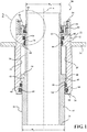
- a latch assembly 20 constructed in accordance with one embodiment of the present invention is generally shown in Figure 1 .
- the latch assembly 20 is used in a vehicle for raising and lowering the height of the vehicle.
- the latch assembly 20 includes a lift housing 22, having a generally tubular shape, disposed annularly about and extending along a center axis A between a first opened end 24 and a second opened end 26.
- the lift housing 22 defines a chamber 28 extending between the first opened end 24 and the second opened end 26.
- a lift spring seat 30 is disposed about the first opened end 24, attached to the lift housing 22, and extends annularly about the center axis A.
- a support tube 32 having a generally cylindrical shape, slidably disposed in the chamber 28. The support tube 32 is disposed in a concentric relationship with the lift housing 22 and extends about the center axis A between a first end 34 and a second end 36.
- the first end 34 of the support tube 32 is located outside of the chamber 28 and axially spaced from the first opened end 24.
- the second end 36 of the support tube 32 is located outside of the chamber 28 and axially spaced from the second opened end 26.
- the lift housing 22 can be connected to an actuator, e.g. a hydraulic actuator, for moving the lift housing 22 axially along the support tube 32.
- the support tube 32 includes a first portion 38 and a second portion 40.
- the first portion 38 of the support tube 32 is disposed adjacent to the first end 34 and extends about the center axis A defining a first diameter D 1 .
- the second portion 40 of the support tube 32 spaced from the first portion 38, disposed adjacent to the second end 36 extending about the center axis A to define a second diameter D 2 with the second diameter D 2 being greater than the first diameter D 1 .
- An intermediate portion 42 extends radially outwardly from the first portion 38, in a perpendicular relationship with the center axis A, to the second portion 40 connecting the first portion 38 with the second portion 40 presenting a shoulder 44 extending along the intermediate portion 42.
- the intermediate portion 42, the lift housing 22, and the first portion 38 of the support tube 32 define a compartment 46 extending between the shoulder 44, the first portion 38 of the support tube 32, and the lift housing 22.
- the intermediate portion 42 includes a projection 48 extending radially outwardly from the intermediate portion 42, perpendicular to the center axis A, to a distal end 50 for engaging the lift housing 22.
- a pair of protrusions 52, 54 include a first protrusion 52 and a second protrusion 54, spaced from one another, is disposed in the chamber 28 and extending radially inwardly from the lift housing 22 toward the center axis A to a terminal end 56 abutting the support tube 32 for engaging the projection 48 to limit axial movement of the support tube 32.
- the first protrusion 52 is located axially spaced from the first opened end 24 and extends radially inwardly toward the center axis A to engage the support tube 32 and also defining a pocket 58 extending between the first protrusion 52, the support tube 32, and the lift housing 22.
- the second protrusion 54 is located at the second end and extends radially inwardly toward the center axis A to engage the support tube 32.
- Each of the protrusions 52, 54 defines at least one groove 60, 62 including a first groove 60 and a second groove 62, axially spaced from one another, and extending annularly about the support tube 32 for receiving an O-ring 64 and provide a seal engagement with the support tube 32 to prevent dust and other particles from entering said chamber 28.
- a moving member 66, 68 is disposed between the support tube 32 and the lift housing 22 for moving the lift housing 22 between an extended position and a lowered position to adjust the height of the vehicle.
- the moving member 66, 68 also maintains the lift housing 22 in the extended position as the lift housing 22 moves from the lowered position to the extended position.
- the second protrusion 54 abuts with the projection 48 and the first protrusion 52 is spaced from the projection 48 to increase the height of the vehicle.
- the first protrusion 52 abuts the projection 48 and the second protrusion 54 is axially spaced from the projection 48 to reduce the height of the vehicle.
- the moving member 66, 68 includes an inner ring 66 and an outer ring 68.
- the inner ring 66 having a generally cylindrical shape, extends about the support tube 32.
- the outer ring 68 is attached to the lift housing 22.
- the inner ring 66 and the outer ring 68 engage one another for translating an axial movement of the support tube 32 into a rotational movement to allow the lift housing 22 to move between the extended position and the lowered position and maintain the lift housing 22 in the extended position.
- the inner ring 66 is disposed in the pocket 58 and extends between an upper end 70 and a lower end 72.
- the lower end 72 of the inner ring 66 is disposed adjacent to the first protrusion 52.
- the inner ring 66 has an interior surface 74 and an exterior surface 76, spaced from one another, extending about the center axis A between the lower end 72 and the upper end 70 with the interior surface 74 being disposed in abutment relationship with the support tube 32.
- a pair of snap rings 78 spaced from one another, and attached to the support tube 32 with one of the snap rings 78 being disposed adjacent to the lower end 72 of the inner ring 66 and another one of the snap rings 78 being disposed adjacent to the upper end 70 of the inner ring 66 to secure the inner ring 66 to the support tube 32.
- the snap rings 78 sandwich the inner ring 66 therebetween to secure the inner ring 66 to the support tube 32.
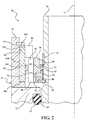
- a bearing 80 is disposed between the interior surface 74 of the inner ring 66 and the support tube 32.
- the bearing 80 is rotatable about the support tube 32 and is attached to the inner ring 66 to allow the inner ring 66 to rotate about the support tube 32 in response to an axial movement of the support tube 32.
- the bearing 80 defines at least one orifice 82.
- the at least one orifice 82 can be a recess 82 extending about the bearing 80.
- a nub 84 extends outwardly from the interior surface 74 of the inner ring 66 and radially inwardly toward the center axis A to connect the inner ring 66 with the bearing 80.
- the nub 84 can extend annularly about the center axis A and the inner ring 66 for engaging the recess 82 of the bearing 80.
- a support ring 86 is disposed between the bearing 80 and one of the snap rings 78, adjacent to the lower end 72 of the inner ring 66 for receiving the bearing 80 and provide support to the bearing 80.
- a plurality of engagement members 88, 90 located between the inner ring 66 and the outer ring 68 for moving the inner ring 66 and the outer ring 68 axially along the center axis A between the extended position and the lowered position.
- the engagement members 88, 90 include a plurality of inner ring teeth 88 extending radially outwardly from the exterior surface 76 of the inner ring 66, circumferentially spaced from one another and along the center axis A, from the lower end 72 of the inner ring 66 to an inner ring teeth end 92 spaced from the upper end 70 of the inner ring 66 for engaging the outer ring 68.
- the exterior surface 76 of the inner ring teeth 88 also defines a plurality of slots 94, circumferentially spaced from one another, extending between the inner ring teeth 88.
- a pair of arms 96 extends outwardly from the inner ring teeth end 92, orthogonal to one another, and tapering toward the upper end 70. As best shown in Figure 4 , one of the arms 96 is longer than another one of the arms 96 to define a cavity 98, having a generally V-shape, extending between the arms 96.
- Each of the inner ring teeth 92 includes a cam 100 extending radially outwardly from the inner ring teeth 90, diagonally across the inner ring teeth 90, at an oblique angle ⁇ relative to the center axis A.
- the outer ring 68 having a generally circular shape, is disposed in the pocket 58 and attached to the lift housing 22 for engaging the inner ring 66.
- the outer ring 68 extends between a top end 102 and a bottom end 104 and having an inner surface 106 and an outer surface 108 extending about the center axis A.
- the outer surface 108 of the outer ring 68 is attached to the lift housing 22.
- a retainer ring 110 having a generally circular shape, is disposed adjacent to the top end 102 of the outer ring 68, attached to the lifting housing 22, and extends about the center axis A to secure the outer ring 68 to the lift housing 22.
- the engagement members 88, 90 include a plurality of outer ring teeth 90, each having a diamond shape, disposed adjacent to the top end 102 of the outer ring 68, circumferentially spaced from one another, extending outwardly from the inner surface 106 of the outer ring 68 for sliding along the arms 86 and engaging the cavity 98 of the inner ring teeth 88 to secure the lift housing 22 in the extended position.
- the another one of the arms 86 defines a slanted surface 112 for receiving the outer ring teeth 90 and allows the lift housing 22 to be moved from the extended position to the lowered position.
- a plurality of pins 114, 116 extends radially inwardly toward the center axis A for slidable engagement with the cam 98 to rotate the inner ring 66 about the support tube 32 and allow the lift housing 22 to move between the extended position and the lowered position.
- the plurality of pins 114, 116 including a first set of pins 114 and a second set of pins 116.
- the first set of pins 114 circumferentially spaced from one another, located adjacent to the bottom end 104 of the outer ring teeth 90 and extending radially inwardly toward the center axis A.
- the second set of pins 116 located radially and circumferentially spaced from the first set of pins 114 for engaging the cam 100 of the inner ring 66.
- the lift housing 22 is in the lowered position. While in the lowered position, the outer ring teeth 90 are disposed adjacent to the lower end 72 of the inner ring 66 and axially below the inner ring teeth 88. Alternatively, while in the lowered position, the outer ring teeth 90 can be received in the slots 94 between the inner ring teeth 88.
- the hydraulic actuator provides an axial movement to the lift housing 22 causing the lift housing 22 to move axially along the center axis A and the support tube 32. As the lift housing 22 moves axially along the support tube 32, the outer ring teeth 90 slide in the slots 94 toward the upper end 70 of the inner ring 66.
- the second set of pins 116 engages the cam 100 and slides along the cam 100.
- the cam 100 translates the axial movement of the lift housing 22 into a rotational movement causing the inner ring 66 to rotate about the support tube 32.
- the outer ring 68 is lowered toward the inner ring 58, i.e.
- the hydraulic actuator stops providing the axial movement to the lift housing 22, the outer ring teeth 90 slides along the arms 96 to further rotate the inner ring 66 and aligns the outer ring teeth 90 with the cavity 98 to allow the cavity 98 to receive the outer ring teeth 90 and define the extended position. Based on the engagement between the outer ring teeth 90 and the inner ring teeth 88, the outer ring teeth 90 is rested in the cavity 98 of the inner ring teeth 88 thereby maintaining the lift housing 22 in the extended position without any additional force input provided by the hydraulic actuator. It should be appreciated that, as the outer ring teeth 90 is moved beyond the inner ring teeth 88, additional axial movement of the lift housing 22 may be possible through the implementation and arrangement additional ribs on the inner surface 106 of the outer ring 68.
- the hydraulic actuator provides another axial movement to the lift housing 22 causing the lift housing 22 to move axially away from the support tube 32.
- the outer ring 68 moves axially away from the inner ring 66.
- the outer ring teeth 90 move axially away from the cavity 98 of the inner ring teeth 88 and the first set of pins 114 engages the cam 100 and slides along the cam 100.
- the axial movement of the lift housing 22 is translated into a rotational movement causing the inner ring 66 to rotate about the support tube 32.
- the outer ring teeth 90 slides along the slanted surface 112 of one of the arm 96 to further rotate the inner ring 66 and aligns the outer ring teeth 90 with the slots 94 between the inner ring teeth 88 to allow the slots 94 to receive the outer ring teeth 90 and define the lowered position.
Landscapes
- Engineering & Computer Science (AREA)
- Mechanical Engineering (AREA)
- Fluid-Damping Devices (AREA)
- Vehicle Body Suspensions (AREA)
Abstract
Description
- The present invention generally relates to a latch assembly for raising and lowering the height of a vehicle.
- Devices for adjusting the height of a vehicle body are known. The devices may be provided in the suspension struts of motor vehicles, in particular, for increasing the ground clearance of motor vehicles or lowering the body for flat road surfaces. Typically, such a device includes a lift housing disposed on a center axis defining a chamber. A support tube is disposed in the chamber with the lift housing being movable along the center axis relative to the support tube. The movement of the lift housing is typically conducted using a hydraulic actuator. However, if the lift housing needs to be held in an extended position to increase the height of a vehicle, a constant hydraulic pressure is required. Accordingly, the hydraulic pump needs to work/restart periodically due to unavoidable internal leaks. Solenoid activated mechanisms, e.g. a pneumatic suspension, are also available for this type of application. However, the solenoid activated mechanisms require electric power input for the locking/unlocking of the solenoid valve which is slow in response time and has a higher energy consumption.
- One such a device is disclosed in
U.S. Patent 9,707,819 - The invention provides for a latch assembly that efficiently raises and lowers the height of the vehicle thereby improving vehicle energy consumption due to reduced air drag. The present invention also maintains the vehicle being in the raised position without additional energy consumption. In addition, the present invention prevents unintentional movements of the rotating latch assembly from the extended position to the lowered position. Further, the present invention provides for a latch assembly that has a simple design and a low cost in production.
- It is one aspect of the present invention to provide a latching assembly. The latching assembly includes a lift housing extending along a center axis between a first opened end and a second opened end and defining a chamber extending therebetween. A support tube is slidably disposed in the chamber and extends about the center axis between a first end and a second end. A moving member is disposed between the support tube and the lift housing for moving the lift housing between an extended position and a lowered position. The moving member includes an inner ring and an outer ring. The inner ring extends about to the support tube. The outer ring is attached to the lift housing for translating an axial movement of the support tube into a rotational movement to secure the lift housing in the extended position and allow the lift housing to move from the extended position to the lowered position. A plurality of engagement members located between the inner ring and the outer ring for moving the inner ring and the outer ring axially along the center axis between the extended position and the lowered position. The engagement members also maintain the lift housing in the extended position without additional energy consumption and prevents unintentional movements of the rotating latch assembly from the extended position to the lowered position.
- It is another aspect of the present invention to provide a latching assembly for raising and lowering vehicle height. The latching assembly includes a lift housing extending along a center axis between a first opened end and a second opened end and defining a chamber extending therebetween. A support tube is slidably disposed in the chamber and extends about the center axis between a first end and a second end. A moving member is disposed between the support tube and the lift housing for moving the lift housing between an extended position and a lowered position. The moving member includes an inner ring and an outer ring. The inner ring extends about the support tube. The outer ring is attached to the lift housing for translating an axial movement of the support tube into a rotational movement to secure the lift housing in the extended position and allow the lift housing to move from the extended position to the lowered position. A bearing is disposed between an interior surface of the inner ring and the support tube with the bearing being rotatable about the support tube. The bearing is attached to the inner ring to allow the inner ring to rotate about the support tube in response to an axial movement of the support tube. A plurality of engagement members located between the inner ring and the outer ring for moving the inner ring and the outer ring axially along the center axis between the extended position and the lowered position. The engagement members also maintain the lift housing in the extended position without additional without additional energy consumption and prevents unintentional movements of the rotating latch assembly from the extended position to the lowered position
- Other advantages of the present invention will be readily appreciated, as the same becomes better understood by reference to the following detailed description when considered in connection with the accompanying drawings wherein:
-
Figure 1 is a cross-sectional perspective view of the latch assembly; -
Figure 2 is an enlarged cross-sectional view of the moving member of the latch assembly; -
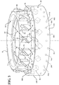
Figure 3 is an exploded perspective view of the moving member of the latch assembly; -
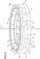
Figure 4 is a perspective view of the moving member of the latch assembly in the lowered position; -
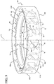
Figure 5 is a perspective view of the moving member of the latch assembly in the extended position; and -
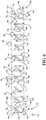
Figure 6 is schematic view showing the movement of the inner ring and the outer ring of the moving member between the extended position and the lowered position. - Referring to the Figures, wherein like numerals indicate corresponding parts throughout the several views, a
latch assembly 20 constructed in accordance with one embodiment of the present invention is generally shown inFigure 1 . Typically, thelatch assembly 20 is used in a vehicle for raising and lowering the height of the vehicle. - Referring to
Figure 1 , thelatch assembly 20 includes alift housing 22, having a generally tubular shape, disposed annularly about and extending along a center axis A between a first openedend 24 and a second openedend 26. Thelift housing 22 defines achamber 28 extending between the first openedend 24 and the second openedend 26. Alift spring seat 30 is disposed about the first openedend 24, attached to thelift housing 22, and extends annularly about the center axis A. Asupport tube 32, having a generally cylindrical shape, slidably disposed in thechamber 28. Thesupport tube 32 is disposed in a concentric relationship with thelift housing 22 and extends about the center axis A between afirst end 34 and asecond end 36. Thefirst end 34 of thesupport tube 32 is located outside of thechamber 28 and axially spaced from the first openedend 24. Thesecond end 36 of thesupport tube 32 is located outside of thechamber 28 and axially spaced from the second openedend 26. It should be appreciated that in one embodiment of the present invention, thelift housing 22 can be connected to an actuator, e.g. a hydraulic actuator, for moving thelift housing 22 axially along thesupport tube 32. - The
support tube 32 includes afirst portion 38 and asecond portion 40. Thefirst portion 38 of thesupport tube 32 is disposed adjacent to thefirst end 34 and extends about the center axis A defining a first diameter D1. Thesecond portion 40 of thesupport tube 32, spaced from thefirst portion 38, disposed adjacent to thesecond end 36 extending about the center axis A to define a second diameter D2 with the second diameter D2 being greater than the first diameter D1. Anintermediate portion 42 extends radially outwardly from thefirst portion 38, in a perpendicular relationship with the center axis A, to thesecond portion 40 connecting thefirst portion 38 with thesecond portion 40 presenting ashoulder 44 extending along theintermediate portion 42. Theintermediate portion 42, thelift housing 22, and thefirst portion 38 of thesupport tube 32 define acompartment 46 extending between theshoulder 44, thefirst portion 38 of thesupport tube 32, and thelift housing 22. - The
intermediate portion 42 includes aprojection 48 extending radially outwardly from theintermediate portion 42, perpendicular to the center axis A, to adistal end 50 for engaging thelift housing 22. A pair ofprotrusions first protrusion 52 and asecond protrusion 54, spaced from one another, is disposed in thechamber 28 and extending radially inwardly from thelift housing 22 toward the center axis A to aterminal end 56 abutting thesupport tube 32 for engaging theprojection 48 to limit axial movement of thesupport tube 32. Thefirst protrusion 52 is located axially spaced from the first openedend 24 and extends radially inwardly toward the center axis A to engage thesupport tube 32 and also defining apocket 58 extending between thefirst protrusion 52, thesupport tube 32, and thelift housing 22. Thesecond protrusion 54 is located at the second end and extends radially inwardly toward the center axis A to engage thesupport tube 32. Each of theprotrusions groove first groove 60 and asecond groove 62, axially spaced from one another, and extending annularly about thesupport tube 32 for receiving an O-ring 64 and provide a seal engagement with thesupport tube 32 to prevent dust and other particles from entering saidchamber 28. - A moving
member support tube 32 and thelift housing 22 for moving thelift housing 22 between an extended position and a lowered position to adjust the height of the vehicle. The movingmember lift housing 22 in the extended position as thelift housing 22 moves from the lowered position to the extended position. When in the extended position, thesecond protrusion 54 abuts with theprojection 48 and thefirst protrusion 52 is spaced from theprojection 48 to increase the height of the vehicle. When in the lowered position, thefirst protrusion 52 abuts theprojection 48 and thesecond protrusion 54 is axially spaced from theprojection 48 to reduce the height of the vehicle. - As best illustrated in
Figures 2-5 , the movingmember inner ring 66 and anouter ring 68. Theinner ring 66, having a generally cylindrical shape, extends about thesupport tube 32. Theouter ring 68 is attached to thelift housing 22. Theinner ring 66 and theouter ring 68 engage one another for translating an axial movement of thesupport tube 32 into a rotational movement to allow thelift housing 22 to move between the extended position and the lowered position and maintain thelift housing 22 in the extended position. - As best shown in
Figure 2 , theinner ring 66 is disposed in thepocket 58 and extends between anupper end 70 and alower end 72. Thelower end 72 of theinner ring 66 is disposed adjacent to thefirst protrusion 52. Theinner ring 66 has aninterior surface 74 and anexterior surface 76, spaced from one another, extending about the center axis A between thelower end 72 and theupper end 70 with theinterior surface 74 being disposed in abutment relationship with thesupport tube 32. A pair of snap rings 78, spaced from one another, and attached to thesupport tube 32 with one of the snap rings 78 being disposed adjacent to thelower end 72 of theinner ring 66 and another one of the snap rings 78 being disposed adjacent to theupper end 70 of theinner ring 66 to secure theinner ring 66 to thesupport tube 32. In other words, the snap rings 78 sandwich theinner ring 66 therebetween to secure theinner ring 66 to thesupport tube 32. - A
bearing 80 is disposed between theinterior surface 74 of theinner ring 66 and thesupport tube 32. Thebearing 80 is rotatable about thesupport tube 32 and is attached to theinner ring 66 to allow theinner ring 66 to rotate about thesupport tube 32 in response to an axial movement of thesupport tube 32. Thebearing 80 defines at least oneorifice 82. In one embodiment of the present, the at least oneorifice 82 can be arecess 82 extending about thebearing 80. Anub 84 extends outwardly from theinterior surface 74 of theinner ring 66 and radially inwardly toward the center axis A to connect theinner ring 66 with thebearing 80. In one embodiment of the present invention, thenub 84 can extend annularly about the center axis A and theinner ring 66 for engaging therecess 82 of thebearing 80. Asupport ring 86 is disposed between the bearing 80 and one of the snap rings 78, adjacent to thelower end 72 of theinner ring 66 for receiving thebearing 80 and provide support to thebearing 80. - As illustrated in
Figures 3-5 , a plurality ofengagement members inner ring 66 and theouter ring 68 for moving theinner ring 66 and theouter ring 68 axially along the center axis A between the extended position and the lowered position. Theengagement members inner ring teeth 88 extending radially outwardly from theexterior surface 76 of theinner ring 66, circumferentially spaced from one another and along the center axis A, from thelower end 72 of theinner ring 66 to an inner ring teeth end 92 spaced from theupper end 70 of theinner ring 66 for engaging theouter ring 68. Theexterior surface 76 of theinner ring teeth 88 also defines a plurality ofslots 94, circumferentially spaced from one another, extending between theinner ring teeth 88. A pair ofarms 96 extends outwardly from the inner ring teeth end 92, orthogonal to one another, and tapering toward theupper end 70. As best shown inFigure 4 , one of thearms 96 is longer than another one of thearms 96 to define acavity 98, having a generally V-shape, extending between thearms 96. Each of theinner ring teeth 92 includes acam 100 extending radially outwardly from theinner ring teeth 90, diagonally across theinner ring teeth 90, at an oblique angle α relative to the center axis A. - Referring back to in
Figure 3 , theouter ring 68, having a generally circular shape, is disposed in thepocket 58 and attached to thelift housing 22 for engaging theinner ring 66. Theouter ring 68 extends between atop end 102 and abottom end 104 and having aninner surface 106 and anouter surface 108 extending about the center axis A. Theouter surface 108 of theouter ring 68 is attached to thelift housing 22. Aretainer ring 110, having a generally circular shape, is disposed adjacent to thetop end 102 of theouter ring 68, attached to the liftinghousing 22, and extends about the center axis A to secure theouter ring 68 to thelift housing 22. - The
engagement members outer ring teeth 90, each having a diamond shape, disposed adjacent to thetop end 102 of theouter ring 68, circumferentially spaced from one another, extending outwardly from theinner surface 106 of theouter ring 68 for sliding along thearms 86 and engaging thecavity 98 of theinner ring teeth 88 to secure thelift housing 22 in the extended position. The another one of thearms 86 defines aslanted surface 112 for receiving theouter ring teeth 90 and allows thelift housing 22 to be moved from the extended position to the lowered position. A plurality ofpins cam 98 to rotate theinner ring 66 about thesupport tube 32 and allow thelift housing 22 to move between the extended position and the lowered position. The plurality ofpins pins 114 and a second set ofpins 116. The first set ofpins 114, circumferentially spaced from one another, located adjacent to thebottom end 104 of theouter ring teeth 90 and extending radially inwardly toward the center axis A. The second set ofpins 116 located radially and circumferentially spaced from the first set ofpins 114 for engaging thecam 100 of theinner ring 66. - In operation, also best illustrated in
Figure 6 , initially, thelift housing 22 is in the lowered position. While in the lowered position, theouter ring teeth 90 are disposed adjacent to thelower end 72 of theinner ring 66 and axially below theinner ring teeth 88. Alternatively, while in the lowered position, theouter ring teeth 90 can be received in theslots 94 between theinner ring teeth 88. To move from the lowered position to the extended position, the hydraulic actuator provides an axial movement to thelift housing 22 causing thelift housing 22 to move axially along the center axis A and thesupport tube 32. As thelift housing 22 moves axially along thesupport tube 32, theouter ring teeth 90 slide in theslots 94 toward theupper end 70 of theinner ring 66. When theouter ring teeth 90 slide past thearms 96 of theinner ring teeth 88, e.g. at a maximum height, the second set ofpins 116 engages thecam 100 and slides along thecam 100. In response to the sliding movement of the second set ofpins 116 along thecam 100, thecam 100 translates the axial movement of thelift housing 22 into a rotational movement causing theinner ring 66 to rotate about thesupport tube 32. As theouter ring 68 is lowered toward theinner ring 58, i.e. the hydraulic actuator stops providing the axial movement to thelift housing 22, theouter ring teeth 90 slides along thearms 96 to further rotate theinner ring 66 and aligns theouter ring teeth 90 with thecavity 98 to allow thecavity 98 to receive theouter ring teeth 90 and define the extended position. Based on the engagement between theouter ring teeth 90 and theinner ring teeth 88, theouter ring teeth 90 is rested in thecavity 98 of theinner ring teeth 88 thereby maintaining thelift housing 22 in the extended position without any additional force input provided by the hydraulic actuator. It should be appreciated that, as theouter ring teeth 90 is moved beyond theinner ring teeth 88, additional axial movement of thelift housing 22 may be possible through the implementation and arrangement additional ribs on theinner surface 106 of theouter ring 68. - To move from the extended position to the lowered position, the hydraulic actuator provides another axial movement to the
lift housing 22 causing thelift housing 22 to move axially away from thesupport tube 32. In response to the axial movement of thelift housing 22, theouter ring 68 moves axially away from theinner ring 66. As a result of this axial movement, theouter ring teeth 90 move axially away from thecavity 98 of theinner ring teeth 88 and the first set ofpins 114 engages thecam 100 and slides along thecam 100. In response to the sliding movement of the first set ofpins 114 along thecam 100, the axial movement of thelift housing 22 is translated into a rotational movement causing theinner ring 66 to rotate about thesupport tube 32. As theouter ring 68 is lowered toward theinner ring 66, theouter ring teeth 90 slides along the slantedsurface 112 of one of thearm 96 to further rotate theinner ring 66 and aligns theouter ring teeth 90 with theslots 94 between theinner ring teeth 88 to allow theslots 94 to receive theouter ring teeth 90 and define the lowered position. - Obviously, many modifications and variations of the present invention are possible in light of the above teachings and may be practiced otherwise than as specifically described while within the scope of the appended claims. These antecedent recitations should be interpreted to cover any combination in which the inventive novelty exercises its utility. The use of the word "said" in the apparatus claims refers to an antecedent that is a positive recitation meant to be included in the coverage of the claims whereas the word "the" precedes a word not meant to be included in the coverage of the claims.
Claims (15)
- A latching assembly comprising:a lift housing extending along a center axis between a first opened end and a second opened end and defining a chamber extending therebetween;a support tube slidably disposed in said chamber extending about said center axis between a first end and a second end;a moving member disposed between said support tube and said lift housing for moving said lift housing between an extended position and a lowered position; said moving member including an inner ring and an outer ring with said inner ring extending about said support tube and said outer ring being attached to said lift housing for translating an axial movement of said support tube into a rotational movement to secure said lift housing in said extended position and allow said lift housing to move from said extended position to said lowered position; anda plurality of engagement members located between said inner ring and said outer ring for moving said inner ring and said outer ring axially along said center axis between said extended position and said lowered position.
- The latching assembly as set forth in claim 1 wherein said engagement members including a plurality of inner ring teeth extending radially outwardly from an exterior surface of said inner ring, circumferentially spaced from one another, and along said center axis to an inner ring teeth end for engaging said outer ring.
- The latching assembly as set forth in claim 2 wherein each of said inner ring teeth including a cam extending radially outwardly from said inner ring teeth and diagonally across said inner ring teeth at an oblique angle relative to said center axis.
- The latching assembly as set forth in claim 2 or 3 further including a pair of arms extending outwardly from said inner ring teeth end orthogonal to one another and tapering toward an upper end with one of said pair of arms being longer than another one of said pair of arms to define a cavity having a V-shape extending between said pair of arms.
- The latching assembly as set forth in claim 4 wherein said engagement members further including a plurality of outer ring teeth, circumferentially spaced from one another, extending outwardly from an inner surface of said outer ring for engaging said inner ring teeth.
- The latching assembly as set forth in claim 5 wherein each of said outer ring teeth has a diamond shape for sliding along said one of said pair of arms and engaging said cavity of said inner ring teeth to secure said lift housing in said extended position.
- The latching assembly as set forth in claim 6 wherein said another one of said pair of arms defines a slanted surface for receiving said outer ring teeth and allows said lift housing to be moved from said extended position to said lowered position.
- The latching assembly as set forth in any one of claims 3 to 7 further including a plurality of pins extending radially inwardly toward said center axis for slidable engagement with said cam to rotate said inner ring about said support tube and allow said lift housing to move between said extended position and said lowered position.
- The latching assembly as set forth in claim 8 wherein said plurality of pins includes a first set of pins, circumferentially spaced from one another, for engaging said cam; and a second set of pins located radially and circumferentially spaced from said first set of pins for engaging said cam of said inner ring.
- The latching assembly as set forth in any one of claims 1 to 9 further including a bearing disposed between an interior surface of said inner ring and said support tube with said bearing being rotatable about said support tube and attached to said inner ring to allow said inner ring to rotate about said support tube in response to an axial movement of said support tube.
- The latching assembly as set forth in claim 10 further including a pair of snap rings, spaced from one another, and attached to said support tube sandwiching said inner ring between said snap rings to secure said inner ring to said support tube.
- The latching assembly as set forth in claim 11 further including a support ring disposed between said bearing and one of said snap rings for receiving said bearing.
- The latching assembly as set forth in any one of claims 10 to 12 wherein said bearing defines at least one orifice, wherein the latching assembly further includes a nub extending outwardly from an interior surface of said inner ring and radially inwardly toward said center axis and annularly about said center axis into said at least one orifice to connect said inner ring to said bearing.
- The latching assembly as set forth in any one of claims 1 to 13 further including a retainer ring disposed adjacent said outer ring, attached to said lifting housing, and extending about said center axis to secure said outer ring to said lift housing.
- The latching assembly as set forth in any one of claims 1 to 14, wherein the latching assembly is used for raising and lowering a height of a vehicle.
Applications Claiming Priority (2)
| Application Number | Priority Date | Filing Date | Title |
|---|---|---|---|
| US201862674612P | 2018-05-22 | 2018-05-22 | |
| US16/384,504 US11135889B2 (en) | 2018-05-22 | 2019-04-15 | Latch assembly for raising and lowering the height of a vehicle |
Publications (2)
| Publication Number | Publication Date |
|---|---|
| EP3594029A1 true EP3594029A1 (en) | 2020-01-15 |
| EP3594029B1 EP3594029B1 (en) | 2021-07-14 |
Family
ID=68613840
Family Applications (1)
| Application Number | Title | Priority Date | Filing Date |
|---|---|---|---|
| EP19173773.3A Active EP3594029B1 (en) | 2018-05-22 | 2019-05-10 | Latch assembly for raising and lowering the height of a vehicle |
Country Status (3)
| Country | Link |
|---|---|
| US (1) | US11135889B2 (en) |
| EP (1) | EP3594029B1 (en) |
| JP (1) | JP6782815B2 (en) |
Families Citing this family (3)
| Publication number | Priority date | Publication date | Assignee | Title |
|---|---|---|---|---|
| US11142034B2 (en) * | 2018-05-21 | 2021-10-12 | Beijingwest Industries Co., Ltd. | Rotating latch assembly for raising and lowering the height of a vehicle |
| US11485186B2 (en) * | 2021-03-10 | 2022-11-01 | Ford Global Technologies, Llc | Spring seat bracket for vehicle suspension |
| KR102624756B1 (en) * | 2022-04-01 | 2024-01-12 | 이정호 | Air Suspension with Air Cup Structure |
Citations (6)
| Publication number | Priority date | Publication date | Assignee | Title |
|---|---|---|---|---|
| WO2009017057A1 (en) * | 2007-07-30 | 2009-02-05 | Ntn Corporation | Bearing with resin pulley |
| DE102014215420A1 (en) * | 2013-08-14 | 2015-02-19 | Schaeffler Technologies Gmbh & Co. Kg | Device for height adjustment of a vehicle body |
| CN106799945A (en) * | 2015-11-26 | 2017-06-06 | 比亚迪股份有限公司 | Suspension elevating adjusting device |
| US9707819B2 (en) | 2013-08-14 | 2017-07-18 | Schaeffler Technologies AG & Co. KG | Device for adjusting the height of a vehicle body |
| CN107757286A (en) * | 2016-08-22 | 2018-03-06 | 比亚迪股份有限公司 | The suspension system of automobile and with its automobile, control method |
| US20180306243A1 (en) * | 2017-04-19 | 2018-10-25 | Seiko Instruments Inc. | Bearing and drive module |
Family Cites Families (11)
| Publication number | Priority date | Publication date | Assignee | Title |
|---|---|---|---|---|
| DE2345503C2 (en) | 1973-09-08 | 1983-04-14 | Stabilus Gmbh, 5400 Koblenz | Opening device for swiveling flaps |
| JP2858452B2 (en) * | 1989-12-15 | 1999-02-17 | カヤバ工業株式会社 | Stay damper |
| US6056333A (en) | 1998-09-08 | 2000-05-02 | Illinois Tool Works Inc. | Floating latch mechanism |
| US6213454B1 (en) | 1999-03-31 | 2001-04-10 | Illinois Tool Works Inc. | Reverse air damper with latching mechanism |
| JP5572504B2 (en) | 2010-09-28 | 2014-08-13 | 日立オートモティブシステムズ株式会社 | Cylinder device |
| DE102014206142A1 (en) | 2013-08-14 | 2015-02-19 | Schaeffler Technologies Gmbh & Co. Kg | Device for height adjustment of a vehicle body |
| US9027938B1 (en) * | 2013-11-15 | 2015-05-12 | David Kasian | Suspension lift kit for quad cycle |
| KR102283696B1 (en) * | 2014-04-10 | 2021-08-02 | 섀플러 테크놀로지스 아게 운트 코. 카게 | Device for adjusting the height of a vehicle body |
| DE102014213341B4 (en) * | 2014-07-09 | 2022-06-15 | Schaeffler Technologies AG & Co. KG | Device for adjusting the height of a vehicle body |
| DE102015217326A1 (en) * | 2015-09-10 | 2017-03-16 | Contitech Vibration Control Gmbh | Suspension strut |
| JP6350511B2 (en) | 2015-12-28 | 2018-07-04 | トヨタ自動車株式会社 | Vehicle height adjustment system |
-
2019
- 2019-04-15 US US16/384,504 patent/US11135889B2/en active Active
- 2019-05-10 EP EP19173773.3A patent/EP3594029B1/en active Active
- 2019-05-22 JP JP2019095621A patent/JP6782815B2/en active Active
Patent Citations (6)
| Publication number | Priority date | Publication date | Assignee | Title |
|---|---|---|---|---|
| WO2009017057A1 (en) * | 2007-07-30 | 2009-02-05 | Ntn Corporation | Bearing with resin pulley |
| DE102014215420A1 (en) * | 2013-08-14 | 2015-02-19 | Schaeffler Technologies Gmbh & Co. Kg | Device for height adjustment of a vehicle body |
| US9707819B2 (en) | 2013-08-14 | 2017-07-18 | Schaeffler Technologies AG & Co. KG | Device for adjusting the height of a vehicle body |
| CN106799945A (en) * | 2015-11-26 | 2017-06-06 | 比亚迪股份有限公司 | Suspension elevating adjusting device |
| CN107757286A (en) * | 2016-08-22 | 2018-03-06 | 比亚迪股份有限公司 | The suspension system of automobile and with its automobile, control method |
| US20180306243A1 (en) * | 2017-04-19 | 2018-10-25 | Seiko Instruments Inc. | Bearing and drive module |
Also Published As
| Publication number | Publication date |
|---|---|
| US20190359021A1 (en) | 2019-11-28 |
| EP3594029B1 (en) | 2021-07-14 |
| JP6782815B2 (en) | 2020-11-11 |
| JP2019202763A (en) | 2019-11-28 |
| US11135889B2 (en) | 2021-10-05 |
Similar Documents
| Publication | Publication Date | Title |
|---|---|---|
| US11135889B2 (en) | Latch assembly for raising and lowering the height of a vehicle | |
| EP3358213B1 (en) | Hydraulic damper with a hydraulic compression stop arrangement | |
| EP3578848B1 (en) | Hydraulic damper with a compression stop assembly | |
| CN104813062A (en) | Hydraulic shock absorber for suspension system and corresponding improved hydraulic stop | |
| EP3287661B1 (en) | Front fork | |
| US10253903B2 (en) | Motor-operated valve | |
| US3757910A (en) | Shock absorber and compression valve assembly | |
| US11400790B2 (en) | Concentric hydraulic ride height actuator for a motor vehicle | |
| CN106799945A (en) | Suspension elevating adjusting device | |
| US11142034B2 (en) | Rotating latch assembly for raising and lowering the height of a vehicle | |
| CN110126578B (en) | Rotary latch assembly for raising and lowering a vehicle | |
| EP3557101B1 (en) | Rotating three way valve for switchable air springs | |
| EP4685075A1 (en) | Container and pump assembly thereof | |
| CN110802994A (en) | Suspension strut and vehicle | |
| CN110126577B (en) | Latch assembly | |
| US7497413B2 (en) | Object support post | |
| EP4224034A1 (en) | Hydraulic rebound stop for monotube damper | |
| CN214630716U (en) | Linear actuator for lifting table | |
| US10895180B2 (en) | Valve lift control device | |
| US9511797B2 (en) | Integral power steering device | |
| EP3992493A2 (en) | Hydraulic damper assembly and a piston for a hydraulic damper assembly | |
| US11787450B2 (en) | Level control system for adjusting the level of a vehicle, in particular a rail vehicle | |
| JP2003275052A (en) | Automatic return device | |
| CN217056576U (en) | Mounting structure, operating assembly and valve | |
| CN220037494U (en) | Valve structure and single crystal furnace |
Legal Events
| Date | Code | Title | Description |
|---|---|---|---|
| PUAI | Public reference made under article 153(3) epc to a published international application that has entered the european phase |
Free format text: ORIGINAL CODE: 0009012 |
|
| STAA | Information on the status of an ep patent application or granted ep patent |
Free format text: STATUS: THE APPLICATION HAS BEEN PUBLISHED |
|
| AK | Designated contracting states |
Kind code of ref document: A1 Designated state(s): AL AT BE BG CH CY CZ DE DK EE ES FI FR GB GR HR HU IE IS IT LI LT LU LV MC MK MT NL NO PL PT RO RS SE SI SK SM TR |
|
| AX | Request for extension of the european patent |
Extension state: BA ME |
|
| STAA | Information on the status of an ep patent application or granted ep patent |
Free format text: STATUS: REQUEST FOR EXAMINATION WAS MADE |
|
| 17P | Request for examination filed |
Effective date: 20200715 |
|
| RBV | Designated contracting states (corrected) |
Designated state(s): AL AT BE BG CH CY CZ DE DK EE ES FI FR GB GR HR HU IE IS IT LI LT LU LV MC MK MT NL NO PL PT RO RS SE SI SK SM TR |
|
| STAA | Information on the status of an ep patent application or granted ep patent |
Free format text: STATUS: EXAMINATION IS IN PROGRESS |
|
| 17Q | First examination report despatched |
Effective date: 20200825 |
|
| GRAP | Despatch of communication of intention to grant a patent |
Free format text: ORIGINAL CODE: EPIDOSNIGR1 |
|
| STAA | Information on the status of an ep patent application or granted ep patent |
Free format text: STATUS: GRANT OF PATENT IS INTENDED |
|
| INTG | Intention to grant announced |
Effective date: 20210128 |
|
| RIN1 | Information on inventor provided before grant (corrected) |
Inventor name: SZYMANSKI, JERZY PIOTR |
|
| GRAS | Grant fee paid |
Free format text: ORIGINAL CODE: EPIDOSNIGR3 |
|
| GRAA | (expected) grant |
Free format text: ORIGINAL CODE: 0009210 |
|
| STAA | Information on the status of an ep patent application or granted ep patent |
Free format text: STATUS: THE PATENT HAS BEEN GRANTED |
|
| AK | Designated contracting states |
Kind code of ref document: B1 Designated state(s): AL AT BE BG CH CY CZ DE DK EE ES FI FR GB GR HR HU IE IS IT LI LT LU LV MC MK MT NL NO PL PT RO RS SE SI SK SM TR |
|
| REG | Reference to a national code |
Ref country code: GB Ref legal event code: FG4D |
|
| REG | Reference to a national code |
Ref country code: DE Ref legal event code: R096 Ref document number: 602019006054 Country of ref document: DE |
|
| REG | Reference to a national code |
Ref country code: IE Ref legal event code: FG4D |
|
| REG | Reference to a national code |
Ref country code: AT Ref legal event code: REF Ref document number: 1410356 Country of ref document: AT Kind code of ref document: T Effective date: 20210815 |
|
| REG | Reference to a national code |
Ref country code: LT Ref legal event code: MG9D |
|
| REG | Reference to a national code |
Ref country code: NL Ref legal event code: MP Effective date: 20210714 |
|
| REG | Reference to a national code |
Ref country code: AT Ref legal event code: MK05 Ref document number: 1410356 Country of ref document: AT Kind code of ref document: T Effective date: 20210714 |
|
| PG25 | Lapsed in a contracting state [announced via postgrant information from national office to epo] |
Ref country code: LT Free format text: LAPSE BECAUSE OF FAILURE TO SUBMIT A TRANSLATION OF THE DESCRIPTION OR TO PAY THE FEE WITHIN THE PRESCRIBED TIME-LIMIT Effective date: 20210714 Ref country code: AT Free format text: LAPSE BECAUSE OF FAILURE TO SUBMIT A TRANSLATION OF THE DESCRIPTION OR TO PAY THE FEE WITHIN THE PRESCRIBED TIME-LIMIT Effective date: 20210714 Ref country code: BG Free format text: LAPSE BECAUSE OF FAILURE TO SUBMIT A TRANSLATION OF THE DESCRIPTION OR TO PAY THE FEE WITHIN THE PRESCRIBED TIME-LIMIT Effective date: 20211014 Ref country code: HR Free format text: LAPSE BECAUSE OF FAILURE TO SUBMIT A TRANSLATION OF THE DESCRIPTION OR TO PAY THE FEE WITHIN THE PRESCRIBED TIME-LIMIT Effective date: 20210714 Ref country code: PT Free format text: LAPSE BECAUSE OF FAILURE TO SUBMIT A TRANSLATION OF THE DESCRIPTION OR TO PAY THE FEE WITHIN THE PRESCRIBED TIME-LIMIT Effective date: 20211115 Ref country code: NL Free format text: LAPSE BECAUSE OF FAILURE TO SUBMIT A TRANSLATION OF THE DESCRIPTION OR TO PAY THE FEE WITHIN THE PRESCRIBED TIME-LIMIT Effective date: 20210714 Ref country code: NO Free format text: LAPSE BECAUSE OF FAILURE TO SUBMIT A TRANSLATION OF THE DESCRIPTION OR TO PAY THE FEE WITHIN THE PRESCRIBED TIME-LIMIT Effective date: 20211014 Ref country code: ES Free format text: LAPSE BECAUSE OF FAILURE TO SUBMIT A TRANSLATION OF THE DESCRIPTION OR TO PAY THE FEE WITHIN THE PRESCRIBED TIME-LIMIT Effective date: 20210714 Ref country code: FI Free format text: LAPSE BECAUSE OF FAILURE TO SUBMIT A TRANSLATION OF THE DESCRIPTION OR TO PAY THE FEE WITHIN THE PRESCRIBED TIME-LIMIT Effective date: 20210714 Ref country code: RS Free format text: LAPSE BECAUSE OF FAILURE TO SUBMIT A TRANSLATION OF THE DESCRIPTION OR TO PAY THE FEE WITHIN THE PRESCRIBED TIME-LIMIT Effective date: 20210714 Ref country code: SE Free format text: LAPSE BECAUSE OF FAILURE TO SUBMIT A TRANSLATION OF THE DESCRIPTION OR TO PAY THE FEE WITHIN THE PRESCRIBED TIME-LIMIT Effective date: 20210714 |
|
| PG25 | Lapsed in a contracting state [announced via postgrant information from national office to epo] |
Ref country code: PL Free format text: LAPSE BECAUSE OF FAILURE TO SUBMIT A TRANSLATION OF THE DESCRIPTION OR TO PAY THE FEE WITHIN THE PRESCRIBED TIME-LIMIT Effective date: 20210714 Ref country code: LV Free format text: LAPSE BECAUSE OF FAILURE TO SUBMIT A TRANSLATION OF THE DESCRIPTION OR TO PAY THE FEE WITHIN THE PRESCRIBED TIME-LIMIT Effective date: 20210714 Ref country code: GR Free format text: LAPSE BECAUSE OF FAILURE TO SUBMIT A TRANSLATION OF THE DESCRIPTION OR TO PAY THE FEE WITHIN THE PRESCRIBED TIME-LIMIT Effective date: 20211015 |
|
| REG | Reference to a national code |
Ref country code: DE Ref legal event code: R097 Ref document number: 602019006054 Country of ref document: DE |
|
| PG25 | Lapsed in a contracting state [announced via postgrant information from national office to epo] |
Ref country code: DK Free format text: LAPSE BECAUSE OF FAILURE TO SUBMIT A TRANSLATION OF THE DESCRIPTION OR TO PAY THE FEE WITHIN THE PRESCRIBED TIME-LIMIT Effective date: 20210714 |
|
| PLBE | No opposition filed within time limit |
Free format text: ORIGINAL CODE: 0009261 |
|
| STAA | Information on the status of an ep patent application or granted ep patent |
Free format text: STATUS: NO OPPOSITION FILED WITHIN TIME LIMIT |
|
| PG25 | Lapsed in a contracting state [announced via postgrant information from national office to epo] |
Ref country code: SM Free format text: LAPSE BECAUSE OF FAILURE TO SUBMIT A TRANSLATION OF THE DESCRIPTION OR TO PAY THE FEE WITHIN THE PRESCRIBED TIME-LIMIT Effective date: 20210714 Ref country code: SK Free format text: LAPSE BECAUSE OF FAILURE TO SUBMIT A TRANSLATION OF THE DESCRIPTION OR TO PAY THE FEE WITHIN THE PRESCRIBED TIME-LIMIT Effective date: 20210714 Ref country code: RO Free format text: LAPSE BECAUSE OF FAILURE TO SUBMIT A TRANSLATION OF THE DESCRIPTION OR TO PAY THE FEE WITHIN THE PRESCRIBED TIME-LIMIT Effective date: 20210714 Ref country code: EE Free format text: LAPSE BECAUSE OF FAILURE TO SUBMIT A TRANSLATION OF THE DESCRIPTION OR TO PAY THE FEE WITHIN THE PRESCRIBED TIME-LIMIT Effective date: 20210714 Ref country code: CZ Free format text: LAPSE BECAUSE OF FAILURE TO SUBMIT A TRANSLATION OF THE DESCRIPTION OR TO PAY THE FEE WITHIN THE PRESCRIBED TIME-LIMIT Effective date: 20210714 Ref country code: AL Free format text: LAPSE BECAUSE OF FAILURE TO SUBMIT A TRANSLATION OF THE DESCRIPTION OR TO PAY THE FEE WITHIN THE PRESCRIBED TIME-LIMIT Effective date: 20210714 |
|
| 26N | No opposition filed |
Effective date: 20220419 |
|
| PG25 | Lapsed in a contracting state [announced via postgrant information from national office to epo] |
Ref country code: IT Free format text: LAPSE BECAUSE OF FAILURE TO SUBMIT A TRANSLATION OF THE DESCRIPTION OR TO PAY THE FEE WITHIN THE PRESCRIBED TIME-LIMIT Effective date: 20210714 |
|
| REG | Reference to a national code |
Ref country code: CH Ref legal event code: PL |
|
| REG | Reference to a national code |
Ref country code: BE Ref legal event code: MM Effective date: 20220531 |
|
| PG25 | Lapsed in a contracting state [announced via postgrant information from national office to epo] |
Ref country code: MC Free format text: LAPSE BECAUSE OF FAILURE TO SUBMIT A TRANSLATION OF THE DESCRIPTION OR TO PAY THE FEE WITHIN THE PRESCRIBED TIME-LIMIT Effective date: 20210714 Ref country code: LU Free format text: LAPSE BECAUSE OF NON-PAYMENT OF DUE FEES Effective date: 20220510 Ref country code: LI Free format text: LAPSE BECAUSE OF NON-PAYMENT OF DUE FEES Effective date: 20220531 Ref country code: CH Free format text: LAPSE BECAUSE OF NON-PAYMENT OF DUE FEES Effective date: 20220531 |
|
| PG25 | Lapsed in a contracting state [announced via postgrant information from national office to epo] |
Ref country code: IE Free format text: LAPSE BECAUSE OF NON-PAYMENT OF DUE FEES Effective date: 20220510 |
|
| PG25 | Lapsed in a contracting state [announced via postgrant information from national office to epo] |
Ref country code: BE Free format text: LAPSE BECAUSE OF NON-PAYMENT OF DUE FEES Effective date: 20220531 |
|
| PG25 | Lapsed in a contracting state [announced via postgrant information from national office to epo] |
Ref country code: MK Free format text: LAPSE BECAUSE OF FAILURE TO SUBMIT A TRANSLATION OF THE DESCRIPTION OR TO PAY THE FEE WITHIN THE PRESCRIBED TIME-LIMIT Effective date: 20210714 Ref country code: CY Free format text: LAPSE BECAUSE OF FAILURE TO SUBMIT A TRANSLATION OF THE DESCRIPTION OR TO PAY THE FEE WITHIN THE PRESCRIBED TIME-LIMIT Effective date: 20210714 |
|
| PG25 | Lapsed in a contracting state [announced via postgrant information from national office to epo] |
Ref country code: HU Free format text: LAPSE BECAUSE OF FAILURE TO SUBMIT A TRANSLATION OF THE DESCRIPTION OR TO PAY THE FEE WITHIN THE PRESCRIBED TIME-LIMIT; INVALID AB INITIO Effective date: 20190510 |
|
| PG25 | Lapsed in a contracting state [announced via postgrant information from national office to epo] |
Ref country code: MT Free format text: LAPSE BECAUSE OF FAILURE TO SUBMIT A TRANSLATION OF THE DESCRIPTION OR TO PAY THE FEE WITHIN THE PRESCRIBED TIME-LIMIT Effective date: 20210714 |
|
| PGFP | Annual fee paid to national office [announced via postgrant information from national office to epo] |
Ref country code: DE Payment date: 20250402 Year of fee payment: 7 |
|
| PGFP | Annual fee paid to national office [announced via postgrant information from national office to epo] |
Ref country code: GB Payment date: 20250401 Year of fee payment: 7 |
|
| PGFP | Annual fee paid to national office [announced via postgrant information from national office to epo] |
Ref country code: FR Payment date: 20250401 Year of fee payment: 7 |
|
| PG25 | Lapsed in a contracting state [announced via postgrant information from national office to epo] |
Ref country code: TR Free format text: LAPSE BECAUSE OF FAILURE TO SUBMIT A TRANSLATION OF THE DESCRIPTION OR TO PAY THE FEE WITHIN THE PRESCRIBED TIME-LIMIT Effective date: 20210714 |