EP3593972A1 - Panel structure for an aircraft and manufacturing method thereof - Google Patents
Panel structure for an aircraft and manufacturing method thereof Download PDFInfo
- Publication number
- EP3593972A1 EP3593972A1 EP18382508.2A EP18382508A EP3593972A1 EP 3593972 A1 EP3593972 A1 EP 3593972A1 EP 18382508 A EP18382508 A EP 18382508A EP 3593972 A1 EP3593972 A1 EP 3593972A1
- Authority
- EP
- European Patent Office
- Prior art keywords
- panel structure
- layer
- aircraft
- cnt
- paper
- Prior art date
- Legal status (The legal status is an assumption and is not a legal conclusion. Google has not performed a legal analysis and makes no representation as to the accuracy of the status listed.)
- Withdrawn
Links
- 238000004519 manufacturing process Methods 0.000 title claims description 8
- OKTJSMMVPCPJKN-UHFFFAOYSA-N Carbon Chemical compound [C] OKTJSMMVPCPJKN-UHFFFAOYSA-N 0.000 claims abstract description 74
- 239000002041 carbon nanotube Substances 0.000 claims abstract description 74
- 229910021393 carbon nanotube Inorganic materials 0.000 claims abstract description 73
- 239000002131 composite material Substances 0.000 claims abstract description 43
- BPQQTUXANYXVAA-UHFFFAOYSA-N Orthosilicate Chemical compound [O-][Si]([O-])([O-])[O-] BPQQTUXANYXVAA-UHFFFAOYSA-N 0.000 claims abstract description 10
- 230000002776 aggregation Effects 0.000 claims abstract description 9
- 238000004220 aggregation Methods 0.000 claims abstract description 9
- 238000000034 method Methods 0.000 claims description 18
- 239000000463 material Substances 0.000 claims description 16
- 239000000835 fiber Substances 0.000 claims description 3
- 239000004753 textile Substances 0.000 claims description 3
- 238000007689 inspection Methods 0.000 abstract description 4
- 230000000694 effects Effects 0.000 abstract description 3
- 230000008439 repair process Effects 0.000 description 17
- 238000010438 heat treatment Methods 0.000 description 11
- 238000009659 non-destructive testing Methods 0.000 description 9
- 230000008569 process Effects 0.000 description 5
- 238000009727 automated fiber placement Methods 0.000 description 3
- 238000009786 automated tape laying Methods 0.000 description 3
- 239000004744 fabric Substances 0.000 description 2
- 238000012423 maintenance Methods 0.000 description 2
- 229910052799 carbon Inorganic materials 0.000 description 1
- 229910021387 carbon allotrope Inorganic materials 0.000 description 1
- 239000004918 carbon fiber reinforced polymer Substances 0.000 description 1
- 230000007123 defense Effects 0.000 description 1
- 230000008021 deposition Effects 0.000 description 1
- 238000005516 engineering process Methods 0.000 description 1
- 230000036541 health Effects 0.000 description 1
- 238000001802 infusion Methods 0.000 description 1
- 238000012544 monitoring process Methods 0.000 description 1
- 239000002086 nanomaterial Substances 0.000 description 1
- 239000002071 nanotube Substances 0.000 description 1
- 238000002604 ultrasonography Methods 0.000 description 1
Images

Classifications
-
- B—PERFORMING OPERATIONS; TRANSPORTING
- B29—WORKING OF PLASTICS; WORKING OF SUBSTANCES IN A PLASTIC STATE IN GENERAL
- B29C—SHAPING OR JOINING OF PLASTICS; SHAPING OF MATERIAL IN A PLASTIC STATE, NOT OTHERWISE PROVIDED FOR; AFTER-TREATMENT OF THE SHAPED PRODUCTS, e.g. REPAIRING
- B29C35/00—Heating, cooling or curing, e.g. crosslinking or vulcanising; Apparatus therefor
- B29C35/02—Heating or curing, e.g. crosslinking or vulcanizing during moulding, e.g. in a mould
- B29C35/0266—Local curing
-
- B—PERFORMING OPERATIONS; TRANSPORTING
- B29—WORKING OF PLASTICS; WORKING OF SUBSTANCES IN A PLASTIC STATE IN GENERAL
- B29C—SHAPING OR JOINING OF PLASTICS; SHAPING OF MATERIAL IN A PLASTIC STATE, NOT OTHERWISE PROVIDED FOR; AFTER-TREATMENT OF THE SHAPED PRODUCTS, e.g. REPAIRING
- B29C35/00—Heating, cooling or curing, e.g. crosslinking or vulcanising; Apparatus therefor
- B29C35/02—Heating or curing, e.g. crosslinking or vulcanizing during moulding, e.g. in a mould
- B29C35/0272—Heating or curing, e.g. crosslinking or vulcanizing during moulding, e.g. in a mould using lost heating elements, i.e. heating means incorporated and remaining in the formed article
-
- B—PERFORMING OPERATIONS; TRANSPORTING
- B29—WORKING OF PLASTICS; WORKING OF SUBSTANCES IN A PLASTIC STATE IN GENERAL
- B29C—SHAPING OR JOINING OF PLASTICS; SHAPING OF MATERIAL IN A PLASTIC STATE, NOT OTHERWISE PROVIDED FOR; AFTER-TREATMENT OF THE SHAPED PRODUCTS, e.g. REPAIRING
- B29C70/00—Shaping composites, i.e. plastics material comprising reinforcements, fillers or preformed parts, e.g. inserts
- B29C70/04—Shaping composites, i.e. plastics material comprising reinforcements, fillers or preformed parts, e.g. inserts comprising reinforcements only, e.g. self-reinforcing plastics
- B29C70/06—Fibrous reinforcements only
- B29C70/08—Fibrous reinforcements only comprising combinations of different forms of fibrous reinforcements incorporated in matrix material, forming one or more layers, and with or without non-reinforced layers
- B29C70/081—Combinations of fibres of continuous or substantial length and short fibres
-
- B—PERFORMING OPERATIONS; TRANSPORTING
- B29—WORKING OF PLASTICS; WORKING OF SUBSTANCES IN A PLASTIC STATE IN GENERAL
- B29C—SHAPING OR JOINING OF PLASTICS; SHAPING OF MATERIAL IN A PLASTIC STATE, NOT OTHERWISE PROVIDED FOR; AFTER-TREATMENT OF THE SHAPED PRODUCTS, e.g. REPAIRING
- B29C70/00—Shaping composites, i.e. plastics material comprising reinforcements, fillers or preformed parts, e.g. inserts
- B29C70/04—Shaping composites, i.e. plastics material comprising reinforcements, fillers or preformed parts, e.g. inserts comprising reinforcements only, e.g. self-reinforcing plastics
- B29C70/28—Shaping operations therefor
- B29C70/54—Component parts, details or accessories; Auxiliary operations, e.g. feeding or storage of prepregs or SMC after impregnation or during ageing
-
- B—PERFORMING OPERATIONS; TRANSPORTING
- B29—WORKING OF PLASTICS; WORKING OF SUBSTANCES IN A PLASTIC STATE IN GENERAL
- B29C—SHAPING OR JOINING OF PLASTICS; SHAPING OF MATERIAL IN A PLASTIC STATE, NOT OTHERWISE PROVIDED FOR; AFTER-TREATMENT OF THE SHAPED PRODUCTS, e.g. REPAIRING
- B29C73/00—Repairing of articles made from plastics or substances in a plastic state, e.g. of articles shaped or produced by using techniques covered by this subclass or subclass B29D
- B29C73/24—Apparatus or accessories not otherwise provided for
- B29C73/30—Apparatus or accessories not otherwise provided for for local pressing or local heating
- B29C73/34—Apparatus or accessories not otherwise provided for for local pressing or local heating for local heating
-
- B—PERFORMING OPERATIONS; TRANSPORTING
- B29—WORKING OF PLASTICS; WORKING OF SUBSTANCES IN A PLASTIC STATE IN GENERAL
- B29C—SHAPING OR JOINING OF PLASTICS; SHAPING OF MATERIAL IN A PLASTIC STATE, NOT OTHERWISE PROVIDED FOR; AFTER-TREATMENT OF THE SHAPED PRODUCTS, e.g. REPAIRING
- B29C35/00—Heating, cooling or curing, e.g. crosslinking or vulcanising; Apparatus therefor
- B29C35/02—Heating or curing, e.g. crosslinking or vulcanizing during moulding, e.g. in a mould
- B29C2035/0211—Heating or curing, e.g. crosslinking or vulcanizing during moulding, e.g. in a mould resistance heating
Definitions
- the present invention refers in general to panel structures for the manufacture of an aircraft, in particular, for its fuselage, empennage section, or any other structure having any type of geometry, also for complex geometry parts having curved skin with omega or T/L shape stringers.
- thermoforming a heatable panel structure for an aircraft which is capable of reaching high temperatures to cure FRP (Fibre Reinforced Prepreg) or textile infusion structures.
- NDT non-destructive testing
- the invention also refers to a method for manufacturing such a panel structure.
- CNTs Carbon nanotubes
- These cylindrical carbon molecules have unusual properties (mechanical properties, electrical conductivity, thermal conductivity%), which are valuable for nanotechnology, electronics, optics and other fields of materials science and technology. Owing to the material's exceptional strength and stiffness, nanotubes show high aspect ratio (length to diameter ratio >100, being much higher in specific cases), significantly larger than for any other material.
- a buckypaper or a CNT paper is a thin self-supporting sheet made from an aggregation of carbon nanotubes.
- CNT papers were produced as a way to handle carbon nanotubes, but, currently they are also being studied and developed in applications in different fields, such as defense (used in vehicle and personal armors), electronics (displays), and also, in the aeronautical industry.
- bonded repairs in composite parts or structures are conventionally performed with the use of an autoclave and/or local heating means for curing the repair material.
- local heating means are used in repairs heating up only the repair material and the area where the repair is applied.
- the present invention overcomes the above mentioned drawbacks by providing a panel structure for an aircraft that can be heated up to reaching curing temperatures for performing bonded repairs in parts or structures.
- One aspect of the present invention refers to a panel structure for an aircraft that comprises at least one composite layer and at least one carbon nanotube (CNT) paper laid over the composite layer, wherein the CNT paper comprises an aggregation of carbon nanotubes suitable to be heated up to the curing temperature of the at least one composite layer.
- CNT carbon nanotube
- the panel structure of the invention is configured to be adapted to simple and complex repair or part shapes.
- the configuration of the panel structure of the invention makes possible to locally heat up the structure when a bonded repair is to be performed.
- the panel structure of the invention is adapted to be inspected with the aid of a thermal camera when heated by applying electrical current.
- SHM Structuretural Health Monitoring
- NDT Non-Destructive Testing
- the panel structure of the invention can be both used as a structure for bonded repairs and for inspecting to identify potential damages suffered by the structure during its service-life and assembly process.
- the panel structure can be used for part manufacturing or part curing purposes when a complete heating of the part is not needed or is to be avoided.
- Another aspect of the invention refers to an aircraft comprising a structure, a skin covering the structure, and a panel structure as described, wherein at least part of the structure skin includes the panel structure.
- the panel structure is placed on top of the structure forming its outermost layer.
- the panel structure can thus be included in any part of the aircraft, in its fuselage or empennage skin, or in any complex geometry part having flat or curved skin with omega or T/L shape stringers.
- another aspect of the invention refers to a method for manufacturing a panel structure for an aircraft, comprising the steps of providing at least one layer of composite material, providing at least one carbon nanotube (CNT) paper, the CNT paper comprising an aggregation of carbon nanotubes suitable to be heated up to the curing temperature of the at least one layer of composite material when the electrical current is applied, and laying the CNT paper over the at least one composite layer to form a heatable panel structure.
- CNT carbon nanotube
- the method of the invention provides a simple and cost-effective way of producing a heatable panel, capable of locally cure composite parts (without the need of an autoclave) and also capable of being inspected (SHM and NDT inspection) in order to evaluate the dimensions and location of any potential damage.
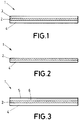
- Figure 1 shows a panel structure 1 for an aircraft according to a first preferred embodiment.
- the panel structure 1 comprises at least one composite layer 3, 4 and at least one CNT paper or sheet 2 laid over the at least one composite layer 3, and wherein the CNT paper 2 comprises an aggregation of carbon nanotubes suitable to be heated up to the curing temperature of the composite layers 3, 4.
- the panel structure 1 of Figure 1 comprises an outer composite layer 3, an inner composite layer 4, and a CNT paper 2 arranged between the outer and inner layers 3, 4.
- the CNT paper 2 of Figure 1 is deposited between two layers of composite material 3, 4, and it is thus integrated in the panel 1.
- the deposition of the CNT paper 2 may be manually or automatically performed by ATL (Automated Tape Laying) or AFP (Automated Fiber Placement) in case of having a laminate skin panel (i.e. CFRP laminate).
- the CNT paper 2 is laid over an outer surface of a composite layer 4.
- the CNT paper 2 may be manually or automatically added by ATL or AFP.
- the panel structure 1 further comprises an Alkaline Earth Silicate layer 5 in contact with the at least one CNT paper 2, forming the outermost layer of the panel structure 1 to avoid the loss of heat. Further, as shown in Figure 3 , and according to another preferred embodiment, the panel structure 1 may further comprise a release film 6 placed between the Alkaline Earth Silicate layer 5 and the at least one CNT paper 2.
- the Alkaline Earth Silicate layer 5 has a width ranging from 0,5mm to 15mm, and preferably, from 1mm to 5 mm.
- the at least one composite layer 3, 4 of the panel structure 1 is formed by Fibre Reinforced Prepreg material.
- the at least one composite layer 3, 4 of the panel structure 1 is formed by textile material (Non Crimp Fabric, Fabrics and tapes).
- the panel structure 1 may further comprise an electrical power source connected to the at least one CNT paper 2 to supply electrical power to the CNT paper 2 for curing the at least one composite layer 3, 4.
- Thermal and electrical conductivity of CNT papers allow to heat up the papers up to the structure curing temperature, attaching a circuit or cable on the CNT paper 2 and applying an electrical power, by resistive heating (Joule effect).
- the panel structure 1 is to be NDT inspected to locate and measure the damage produced.
- the additional layer can be also used for SHM and NDT inspection.
- Figure 4 shows a preferred embodiment for the manufacturing method of the invention.
- the method for manufacturing a panel structure 1 for an aircraft comprises the steps of providing at least one layer of composite material 3, providing at least one CNT paper 2, the CNT paper 2 comprising an aggregation of carbon nanotubes suitable to be heated up to the curing temperature of the panel structure 1, and attaching the CNT paper 2 to the at least one composite layer 3, 4 to form a heatable panel structure 1.
- the CNT paper 2 (usually supplied in rolls) is attached to two layers of composite material 3, 4.
- the method comprises providing an inner 4 and an outer layer of composite material 3, providing a CNT paper 2, the CNT paper 2 comprising an aggregation of carbon nanotubes suitable to be heated up to the curing temperature of composite materials, and attaching the CNT paper 2 to the at least one composite layer 3, 4 to form a heatable panel structure 1.
Landscapes
- Engineering & Computer Science (AREA)
- Mechanical Engineering (AREA)
- Physics & Mathematics (AREA)
- Health & Medical Sciences (AREA)
- Oral & Maxillofacial Surgery (AREA)
- Thermal Sciences (AREA)
- Chemical & Material Sciences (AREA)
- Composite Materials (AREA)
- Moulding By Coating Moulds (AREA)
- Laminated Bodies (AREA)
Abstract
Description
- The present invention refers in general to panel structures for the manufacture of an aircraft, in particular, for its fuselage, empennage section, or any other structure having any type of geometry, also for complex geometry parts having curved skin with omega or T/L shape stringers.
- More in particular, it is an object of the present invention to provide a heatable panel structure for an aircraft, which is capable of reaching high temperatures to cure FRP (Fibre Reinforced Prepreg) or textile infusion structures.
- It is also an object of the present invention to provide a panel structure for an aircraft, which is adapted to identify the dimension and location of any accidental damage when inspected under non-destructive testing (NDT) techniques.
- The invention also refers to a method for manufacturing such a panel structure.
- CNT Carbon nanotubes (CNTs) are allotropes of carbon with a cylindrical nanostructure. These cylindrical carbon molecules have unusual properties (mechanical properties, electrical conductivity, thermal conductivity...), which are valuable for nanotechnology, electronics, optics and other fields of materials science and technology. Owing to the material's exceptional strength and stiffness, nanotubes show high aspect ratio (length to diameter ratio >100, being much higher in specific cases), significantly larger than for any other material.
- A buckypaper or a CNT paper is a thin self-supporting sheet made from an aggregation of carbon nanotubes. Originally, CNT papers were produced as a way to handle carbon nanotubes, but, currently they are also being studied and developed in applications in different fields, such as defense (used in vehicle and personal armors), electronics (displays), and also, in the aeronautical industry.
- In the aeronautical field, bonded repairs in composite parts or structures are conventionally performed with the use of an autoclave and/or local heating means for curing the repair material.
- Repairs heating up the complete part up to original curing temperature are to be avoided, as thermal deformation and damages can be produced if the part is not properly placed in its curing mould or if the curing mould is not available for the repair. Composite repairs are typically made curing the original part material in the autoclave. Additionally, the time the part (already cured) is at curing temperature has to be also controlled and reduced in order not to affect its mechanical properties.
- For these reasons, if possible, local heating means are used in repairs heating up only the repair material and the area where the repair is applied.
- Conventional local heating means used in bonded repairs are heating blankets and warm air boxes. However, both of these local heating means are limited in size or/and adaptability to the repair shape. Therefore, reparability of a composite part using original material (to be cured at original part temperature) is mainly limited by the heating means.
- It would therefore be desirable to provide technical means that improve the bonded repairs of parts or structures whatever the size or shape of the repair area or part.
- In another aspect, during the assembly process or the in-service life of an aircraft, accidental damages can be produced in external or internal parts or structures. These damages can be caused by external reasons or even during the inspection and maintenance process carried out on the aircraft.
- Nowadays, these damages produced during the assembly process and the in-service operation of an aircraft are inspected by NDT methods according to the corresponding maintenance manual. Also, these damages can be visually identified, specially, during the operation of the aircraft.
- Further, current NDT methods (e.g. ultrasounds) require in most of the cases direct access to the structure and disassembly of surrounding elements.
- It would therefore be also desirable that the technical means used for improving the bonded repairs in parts or structures could also be used to inspect these parts or structures to evaluate the dimension and location of potential damages without the need of being close or having access to the structure.
- The present invention overcomes the above mentioned drawbacks by providing a panel structure for an aircraft that can be heated up to reaching curing temperatures for performing bonded repairs in parts or structures.
- One aspect of the present invention refers to a panel structure for an aircraft that comprises at least one composite layer and at least one carbon nanotube (CNT) paper laid over the composite layer, wherein the CNT paper comprises an aggregation of carbon nanotubes suitable to be heated up to the curing temperature of the at least one composite layer.
- This way, a new panel structure is provided in which the cure cycle needed for curing the structure will be applied by means of the CNT paper, due to its good thermal and electrical conductivity. The curing takes place due to the Joule effect when electrical current is applied to the structure via the CNT paper.
- Further, due to the flexibility of CNT papers, the panel structure of the invention is configured to be adapted to simple and complex repair or part shapes.
- Also, since the CNT paper can be locally applied, the configuration of the panel structure of the invention makes possible to locally heat up the structure when a bonded repair is to be performed.
- In addition, due to the good thermal and electrical conductivity of the CNT paper, the panel structure of the invention is adapted to be inspected with the aid of a thermal camera when heated by applying electrical current. This way, the invention can be used for SHM (Structural Health Monitoring) and NDT (Non-Destructive Testing) in order to detect and characterize any accidental damage contained in the structure during its subsequent assembly process and in-service life.
- This way, the panel structure of the invention can be both used as a structure for bonded repairs and for inspecting to identify potential damages suffered by the structure during its service-life and assembly process.
- Further, the panel structure can be used for part manufacturing or part curing purposes when a complete heating of the part is not needed or is to be avoided.
- Another aspect of the invention refers to an aircraft comprising a structure, a skin covering the structure, and a panel structure as described, wherein at least part of the structure skin includes the panel structure. Preferably, the panel structure is placed on top of the structure forming its outermost layer.
- The panel structure can thus be included in any part of the aircraft, in its fuselage or empennage skin, or in any complex geometry part having flat or curved skin with omega or T/L shape stringers.
- Finally, another aspect of the invention refers to a method for manufacturing a panel structure for an aircraft, comprising the steps of providing at least one layer of composite material, providing at least one carbon nanotube (CNT) paper, the CNT paper comprising an aggregation of carbon nanotubes suitable to be heated up to the curing temperature of the at least one layer of composite material when the electrical current is applied, and laying the CNT paper over the at least one composite layer to form a heatable panel structure.
- The method of the invention provides a simple and cost-effective way of producing a heatable panel, capable of locally cure composite parts (without the need of an autoclave) and also capable of being inspected (SHM and NDT inspection) in order to evaluate the dimensions and location of any potential damage.
- For a better comprehension of the invention, the following drawings are provided for illustrative and non-limiting purposes, wherein:
-
Figure 1 shows a schematic perspective view of a panel structure, according to a first embodiment of the present invention. -
Figure 2 shows a schematic perspective view of a panel structure, according to a second embodiment of the present invention. -
Figure 3 shows a schematic perspective view of a panel structure, according to a third embodiment of the present invention. -
Figure 4 shows a schematic perspective view of the arrangement of the CNT paper between two composite layers to form the panel structure ofFigure 1 . -
Figure 1 shows a panel structure 1 for an aircraft according to a first preferred embodiment. According to the invention, the panel structure 1 comprises at least onecomposite layer sheet 2 laid over the at least onecomposite layer 3, and wherein theCNT paper 2 comprises an aggregation of carbon nanotubes suitable to be heated up to the curing temperature of thecomposite layers - The panel structure 1 of
Figure 1 comprises anouter composite layer 3, aninner composite layer 4, and aCNT paper 2 arranged between the outer andinner layers - The
CNT paper 2 ofFigure 1 is deposited between two layers ofcomposite material CNT paper 2 may be manually or automatically performed by ATL (Automated Tape Laying) or AFP (Automated Fiber Placement) in case of having a laminate skin panel (i.e. CFRP laminate). - In the embodiment of
Figure 2 , theCNT paper 2 is laid over an outer surface of acomposite layer 4. Again, theCNT paper 2 may be manually or automatically added by ATL or AFP. - According to another preferred embodiment, the panel structure 1 further comprises an Alkaline Earth
Silicate layer 5 in contact with the at least oneCNT paper 2, forming the outermost layer of the panel structure 1 to avoid the loss of heat. Further, as shown inFigure 3 , and according to another preferred embodiment, the panel structure 1 may further comprise arelease film 6 placed between the Alkaline EarthSilicate layer 5 and the at least oneCNT paper 2. - Preferably, the Alkaline Earth
Silicate layer 5 has a width ranging from 0,5mm to 15mm, and preferably, from 1mm to 5 mm. - Preferably, the at least one
composite layer - Alternatively, the at least one
composite layer - According to another preferred embodiment, the panel structure 1 may further comprise an electrical power source connected to the at least one
CNT paper 2 to supply electrical power to theCNT paper 2 for curing the at least onecomposite layer - Thermal and electrical conductivity of CNT papers allow to heat up the papers up to the structure curing temperature, attaching a circuit or cable on the
CNT paper 2 and applying an electrical power, by resistive heating (Joule effect). - In addition, when an accidental damage is produced, the panel structure 1 is to be NDT inspected to locate and measure the damage produced. In these structures, where at least one CNT paper is used for curing, the additional layer can be also used for SHM and NDT inspection. By applying a small electrical power to the already installed material, due to the electrical conductivity of the material, if the heating efficiency of the material is not as good as expected, it can be concluded there is damage in the CNT paper/repaired structure. Additionally, the structure is heated up homogenously in those areas where CNT paper material is not damaged and in a different manner where the CNT paper is damaged. So by using a thermal camera, areas, where CNT material/repaired structure is damaged, can be easily localized due to the different thermal behaviour considering the intact structure.
- Finally,
Figure 4 shows a preferred embodiment for the manufacturing method of the invention. - According to the invention, the method for manufacturing a panel structure 1 for an aircraft comprises the steps of providing at least one layer of
composite material 3, providing at least oneCNT paper 2, theCNT paper 2 comprising an aggregation of carbon nanotubes suitable to be heated up to the curing temperature of the panel structure 1, and attaching theCNT paper 2 to the at least onecomposite layer - Preferably, and as shown in
Figure 4 , the CNT paper 2 (usually supplied in rolls) is attached to two layers ofcomposite material composite material 3, providing aCNT paper 2, theCNT paper 2 comprising an aggregation of carbon nanotubes suitable to be heated up to the curing temperature of composite materials, and attaching theCNT paper 2 to the at least onecomposite layer
Claims (15)
- Panel structure (1) for an aircraft comprising at least one composite layer (3, 4) and at least one carbon nanotube (CNT) paper (2) laid over the at least one composite layer (3, 4), wherein the CNT paper (2) comprises an aggregation of carbon nanotubes suitable to be heated up to the curing temperature of the at least one composite layer (3, 4).
- Panel structure (1) for an aircraft, according to claim 1, further comprising a electrical power source connected to the at least one CNT paper (2) to supply electrical power to the CNT paper (2) for curing the at least one composite layer (3, 4).
- Panel structure (1) for an aircraft, according to any of the preceding claims, wherein the at least one CNT paper (2) is embedded between at least two composite layers (3, 4).
- Panel structure (1) for an aircraft, according to any of claims 1-2, wherein the at least one CNT paper (2) is placed on top of the structure (1) forming its outermost layer.
- Panel structure (1) for an aircraft, according to claim 4, further comprising an Alkaline Earth Silicate layer (5) on top of the at least one CNT paper (2), forming the outermost layer of the panel structure (1) to avoid the loss of heat.
- Panel structure (1) for an aircraft, according to claim 5, further comprising a release film (6) placed between the Alkaline Earth Silicate layer (5) and the at least one CNT paper (2).
- Panel structure (1) for an aircraft, according to any of claims 5-6, wherein the Alkaline Earth Silicate layer (5) has a width ranging from 0,5mm to 15mm, and preferably, from 1mm to 5 mm.
- Panel structure (1) for an aircraft, according to any of the preceding claims, wherein the at least one composite layer (3, 4) is formed by Fibre Reinforced Prepreg material.
- Panel structure (1) for an aircraft, according to any of claims 1-7, wherein the at least one composite layer (3, 4) is formed by textile material.
- An aircraft, comprising a structure, a skin covering the structure, and a panel structure (1) according to any of the preceding claims, wherein at least part of the structure skin includes the panel structure (1).
- Method for manufacturing a panel structure (1) for an aircraft, comprising the steps of:providing at least one layer of composite material (3, 4),providing at least one carbon nanotube (CNT) paper (2), the CNT paper (2) comprising an aggregation of carbon nanotubes suitable to be heated up to the curing temperature of the at least one layer of composite material (3, 4),laying the CNT paper (2) over the at least one composite layer (3, 4) to form a heatable panel structure (1).
- Method according to claim 11, wherein the CNT paper (2) is attached to two layers of composite material (3, 4).
- Method according to any of claims 11-12, further comprising attaching an Alkaline Earth Silicate layer (5) on top of the at least one CNT paper (2) to form the outermost layer of the panel structure (1) in order to avoid the loss of heat.
- Method according to claim 13, further comprising placing a release film (6) between the Alkaline Earth Silicate layer (5) and the at least one CNT paper (2).
- Method according to any of claims 13-14, wherein the Alkaline Earth Silicate layer (5) has a width ranging from 0,5mm to 15mm, and preferably, from 1mm to 5 mm.
Priority Applications (1)
| Application Number | Priority Date | Filing Date | Title |
|---|---|---|---|
| EP18382508.2A EP3593972A1 (en) | 2018-07-09 | 2018-07-09 | Panel structure for an aircraft and manufacturing method thereof |
Applications Claiming Priority (1)
| Application Number | Priority Date | Filing Date | Title |
|---|---|---|---|
| EP18382508.2A EP3593972A1 (en) | 2018-07-09 | 2018-07-09 | Panel structure for an aircraft and manufacturing method thereof |
Publications (1)
| Publication Number | Publication Date |
|---|---|
| EP3593972A1 true EP3593972A1 (en) | 2020-01-15 |
Family
ID=62909475
Family Applications (1)
| Application Number | Title | Priority Date | Filing Date |
|---|---|---|---|
| EP18382508.2A Withdrawn EP3593972A1 (en) | 2018-07-09 | 2018-07-09 | Panel structure for an aircraft and manufacturing method thereof |
Country Status (1)
| Country | Link |
|---|---|
| EP (1) | EP3593972A1 (en) |
Cited By (1)
| Publication number | Priority date | Publication date | Assignee | Title |
|---|---|---|---|---|
| CN111204063A (en) * | 2020-03-23 | 2020-05-29 | 中国民用航空飞行学院 | Curing method and curing system of glass fiber reinforced resin matrix composite |
Citations (1)
| Publication number | Priority date | Publication date | Assignee | Title |
|---|---|---|---|---|
| EP1628067A1 (en) * | 2004-08-20 | 2006-02-22 | Gaz De France (Service National) | In situ repair method for a conduit or a reservoir of thermofusible material and device for carrying out said method |
-
2018
- 2018-07-09 EP EP18382508.2A patent/EP3593972A1/en not_active Withdrawn
Patent Citations (1)
| Publication number | Priority date | Publication date | Assignee | Title |
|---|---|---|---|---|
| EP1628067A1 (en) * | 2004-08-20 | 2006-02-22 | Gaz De France (Service National) | In situ repair method for a conduit or a reservoir of thermofusible material and device for carrying out said method |
Non-Patent Citations (1)
| Title |
|---|
| XIAOKUI XU ET AL.: "CARBON NANOTUBE FILM ENGINEERED FIBER REINFORCED POLYMER COMPOSITES", 25 August 2017 (2017-08-25), Xi'an, XP002787697, Retrieved from the Internet <URL:https://www.google.com/url?sa=t&rct=j&q=&esrc=s&source=web&cd=12&ved=2ahUKEwjxtbrCmN7fAhWB_KQKHRuWBFMQFjALegQIBBAC&url=http%3A%2F%2Fwww.iccm-central.org%2FProceedings%2FICCM21proceedings%2Fpapers%2F4393.pdf&usg=AOvVaw0Q8nDMLl9gHV8SGelS7XMX> [retrieved on 20190108] * |
Cited By (1)
| Publication number | Priority date | Publication date | Assignee | Title |
|---|---|---|---|---|
| CN111204063A (en) * | 2020-03-23 | 2020-05-29 | 中国民用航空飞行学院 | Curing method and curing system of glass fiber reinforced resin matrix composite |
Similar Documents
| Publication | Publication Date | Title |
|---|---|---|
| KR101819760B1 (en) | Surrogate patch for composite repair process | |
| Falzon et al. | Development and evaluation of a novel integrated anti-icing/de-icing technology for carbon fibre composite aerostructures using an electro-conductive textile | |
| US9829450B2 (en) | Structural health monitoring | |
| US10717251B2 (en) | Repair patch for composite structure and associated method | |
| BR112021000792B1 (en) | METHOD AND INSTALLATION FOR WELDING AT LEAST TWO RIGID PARTS | |
| US9873527B2 (en) | System and method to map a thermal profile of a composite structure using a thermochromatic witness assembly | |
| US9336588B2 (en) | Joint assemblies and method of inspecting thereof | |
| Tu et al. | Laser induced graphene-based out-of-autoclave curing of fiberglass reinforced polymer matrix composites | |
| US9441652B2 (en) | Joint assembly and method of assembling the same | |
| Suzuki et al. | Impact-damage visualization in CFRP by resistive heating: Development of a new detection method for indentations caused by impact loads | |
| US11607852B2 (en) | Resistance welding methods and apparatus | |
| Jung et al. | Strain sensing and progressive failure monitoring of glass-fiber-reinforced composites using percolated carbon nanotube networks | |
| Wang et al. | Strain monitoring using carbon nanotube Buckypaper sensor on composite repaired structure | |
| Pansart | Prepreg processing of advanced fibre-reinforced polymer (FRP) composites | |
| EP2950085A1 (en) | Improved structural health monitoring | |
| GB2526569A (en) | Improved structural health monitoring | |
| EP2099601A2 (en) | Method, system and apparatus to produce a composite item based on a layup of sheet molding materials and organized fiber structure prepreg | |
| US20230399113A1 (en) | Heating thermoplastic material using electric heater(s) for thermal anti-icing system | |
| Zehni et al. | Structural health monitoring of scarf bonded repaired glass/epoxy laminates interleaved with carbon non-woven veil | |
| US20140202630A1 (en) | Method and Apparatus for Reducing Porosities in Composite Resin Parts | |
| CA3019079A1 (en) | Vacuum film with ventilation properties | |
| Ju et al. | Experimental study on the tensile properties of composites with Cr20Ni80 TFP electric heating layer under energization | |
| Grammatikos | Structural integrity assessment of aerostructures using innovative Non-Destructive Evaluation Rechniques | |
| Bily et al. | Damage detection in composite interfaces through carbon nanotube reinforcement | |
| Fiorentino | The Tough get Tougher? |
Legal Events
| Date | Code | Title | Description |
|---|---|---|---|
| PUAI | Public reference made under article 153(3) epc to a published international application that has entered the european phase |
Free format text: ORIGINAL CODE: 0009012 |
|
| STAA | Information on the status of an ep patent application or granted ep patent |
Free format text: STATUS: THE APPLICATION HAS BEEN PUBLISHED |
|
| AK | Designated contracting states |
Kind code of ref document: A1 Designated state(s): AL AT BE BG CH CY CZ DE DK EE ES FI FR GB GR HR HU IE IS IT LI LT LU LV MC MK MT NL NO PL PT RO RS SE SI SK SM TR |
|
| AX | Request for extension of the european patent |
Extension state: BA ME |
|
| STAA | Information on the status of an ep patent application or granted ep patent |
Free format text: STATUS: REQUEST FOR EXAMINATION WAS MADE |
|
| 17P | Request for examination filed |
Effective date: 20200714 |
|
| RBV | Designated contracting states (corrected) |
Designated state(s): AL AT BE BG CH CY CZ DE DK EE ES FI FR GB GR HR HU IE IS IT LI LT LU LV MC MK MT NL NO PL PT RO RS SE SI SK SM TR |
|
| STAA | Information on the status of an ep patent application or granted ep patent |
Free format text: STATUS: EXAMINATION IS IN PROGRESS |
|
| 17Q | First examination report despatched |
Effective date: 20220208 |
|
| STAA | Information on the status of an ep patent application or granted ep patent |
Free format text: STATUS: THE APPLICATION IS DEEMED TO BE WITHDRAWN |
|
| 18D | Application deemed to be withdrawn |
Effective date: 20220621 |