EP3593903A1 - Liquid filtering system with vacuum valve - Google Patents
Liquid filtering system with vacuum valve Download PDFInfo
- Publication number
- EP3593903A1 EP3593903A1 EP18182730.4A EP18182730A EP3593903A1 EP 3593903 A1 EP3593903 A1 EP 3593903A1 EP 18182730 A EP18182730 A EP 18182730A EP 3593903 A1 EP3593903 A1 EP 3593903A1
- Authority
- EP
- European Patent Office
- Prior art keywords
- vacuum
- adapter
- base
- locking position
- cradle
- Prior art date
- Legal status (The legal status is an assumption and is not a legal conclusion. Google has not performed a legal analysis and makes no representation as to the accuracy of the status listed.)
- Granted
Links
Images
Classifications
-
- B—PERFORMING OPERATIONS; TRANSPORTING
- B01—PHYSICAL OR CHEMICAL PROCESSES OR APPARATUS IN GENERAL
- B01D—SEPARATION
- B01D35/00—Filtering devices having features not specifically covered by groups B01D24/00 - B01D33/00, or for applications not specifically covered by groups B01D24/00 - B01D33/00; Auxiliary devices for filtration; Filter housing constructions
- B01D35/30—Filter housing constructions
- B01D35/306—Filter mounting adapter
-
- B—PERFORMING OPERATIONS; TRANSPORTING
- B01—PHYSICAL OR CHEMICAL PROCESSES OR APPARATUS IN GENERAL
- B01D—SEPARATION
- B01D37/00—Processes of filtration
-
- B—PERFORMING OPERATIONS; TRANSPORTING
- B01—PHYSICAL OR CHEMICAL PROCESSES OR APPARATUS IN GENERAL
- B01D—SEPARATION
- B01D29/00—Filters with filtering elements stationary during filtration, e.g. pressure or suction filters, not covered by groups B01D24/00 - B01D27/00; Filtering elements therefor
- B01D29/085—Funnel filters; Holders therefor
-
- B—PERFORMING OPERATIONS; TRANSPORTING
- B01—PHYSICAL OR CHEMICAL PROCESSES OR APPARATUS IN GENERAL
- B01D—SEPARATION
- B01D35/00—Filtering devices having features not specifically covered by groups B01D24/00 - B01D33/00, or for applications not specifically covered by groups B01D24/00 - B01D33/00; Auxiliary devices for filtration; Filter housing constructions
- B01D35/14—Safety devices specially adapted for filtration; Devices for indicating clogging
-
- B—PERFORMING OPERATIONS; TRANSPORTING
- B01—PHYSICAL OR CHEMICAL PROCESSES OR APPARATUS IN GENERAL
- B01D—SEPARATION
- B01D35/00—Filtering devices having features not specifically covered by groups B01D24/00 - B01D33/00, or for applications not specifically covered by groups B01D24/00 - B01D33/00; Auxiliary devices for filtration; Filter housing constructions
- B01D35/30—Filter housing constructions
-
- B—PERFORMING OPERATIONS; TRANSPORTING
- B01—PHYSICAL OR CHEMICAL PROCESSES OR APPARATUS IN GENERAL
- B01D—SEPARATION
- B01D2201/00—Details relating to filtering apparatus
- B01D2201/16—Valves
-
- B—PERFORMING OPERATIONS; TRANSPORTING
- B01—PHYSICAL OR CHEMICAL PROCESSES OR APPARATUS IN GENERAL
- B01D—SEPARATION
- B01D2201/00—Details relating to filtering apparatus
- B01D2201/20—Pressure-related systems for filters
- B01D2201/204—Systems for applying vacuum to filters
-
- B—PERFORMING OPERATIONS; TRANSPORTING
- B01—PHYSICAL OR CHEMICAL PROCESSES OR APPARATUS IN GENERAL
- B01D—SEPARATION
- B01D2201/00—Details relating to filtering apparatus
- B01D2201/30—Filter housing constructions
- B01D2201/301—Details of removable closures, lids, caps, filter heads
- B01D2201/305—Snap, latch or clip connecting means
Definitions
- the invention relates to a liquid filtering system comprising:
- Liquid filtering systems of said kind are known from WO 2007/028157 A1 .
- That document discloses a liquid filtering system with a filtering apparatus essentially consisting of a bottle on top of which a filter funnel is fixed by means of an adapter. On the bottom of said filter funnel there is a filter layer through which a liquid filled into the funnel is filtered and output into the bottle.
- a driving force to drive the liquid through the filter layer into the bottle said bottle is coupled to a vacuum source wherein the according vacuum receiving port is part of said adapter.
- Said adapter vacuum receiving port essentially is a vertically directed, downward-facing hole constituting the end of an internal conduct.
- a corresponding upward-facing hole constituting the end of a connection conduct to the vacuum source is located on the rim of a cradle held by a base stand.
- the prior art liquid filtering system is easy to be maloperated. Especially the sealed vacuum connection is quite instable. Also, after having positioned the filtering apparatus in the cradle the vacuum has to be turned on and it has to be turned off after the filtering process has finished, both in separate steps which is time consuming and likely to be accidently omitted.
- the problem to be solved by the invention is to provide a liquid filtering system easier to handle and better protected against maloperation.
- liquid filtering system according to claim 1, especially by a liquid filtering system having the features of the generic part of claim 1 and being characterized in that said base vacuum delivery port comprises a vacuum valve constituted as a mechanical normally-closed valve automatically forced open when said filtering apparatus is locked to said cradle.
- the principal vacuum valve is not a manually operable valve but a valve that is normally, i.e. whenever the filtering apparatus is not located in the cradle, in its closed state.
- said vacuum valve may comprise a vacuum channel, a valve body being coaxially dislocatable within said vacuum channel, and a valve seat against which said valve body is sealingly pressed by according spring means.
- the filtering apparatus especially its adapter comprises a structure that automatically opens said vacuum valve when the filtering apparatus is locked to the cradle.
- the adapter may comprise a stiff pipe socket that is introduced into said vacuum channel when the adapter is locked to the cradle.
- the pipe socket gets into contact with the valve body and dislocates it within the vacuum channel opening the vacuum valve. As soon as the filtering apparatus is removed from the cradle the vacuum valve closes again. This makes the whole system not only safe against maloperation but also saves operation time and, thus, renders increases the system more efficient.
- said adapter vacuum receiving port comprises, as exemplarily mentioned above, a stiff pipe socket which, in said locking position, extends through a base port opening of said base vacuum delivery port, dislocating a valve body of said vacuum valve from its closing position to its opening position.
- said pipe socket may dislocate said valve body against a reset force of a spring applying a closing force to said valve body. Said reset force has to be stronger than the vacuum force exercised by the vacuum source in order to prevent the valve to be sucked open by the vacuum.
- said vacuum valve may comprise:
- said base vacuum delivery port may comprise a vacuum sealing ring between said base port opening and said vacuum valve, said sealing ring, in said locking position, being sealingly penetrated by said pipe socket.
- said sealing ring is an elastomeric ring having a first axial end, a second axial end, and a central sector located axially between said first and second axial ends, wherein its clear diameter at said first and second ends is larger than the outer diameter of said pipe socket, and wherein its clear diameter at said central sector is as large as or smaller than the outer diameter of said pipe socket.
- the wall of said sealing ring is V-shaped. This shape implies two advantages. On the one hand, the slope closer to the base port opening facilitates the penetration of the pipe socket.
- the slope closer to valve provides a self-sealing effect on the basis of the so called Bernoulli Effect: A stream of air through an axially diminishing gap between two walls relatively movable to each other forces said walls to further approach each other and finally close said gap. Air may stream between the vacuum channel and the interior of the pipe socket through said openings.
- valve body has the shape of a ball.
- pipe socket has a round profile. If a rectangularly cut, round-profiled pipe socket coaxially hits a ball-shaped valve body said valve body obstructs the entrance of said pipe socket running counter to the goal of opening the valve.
- side wall of said pipe socket may comprise at least one aperture located, in said locking position, axially between said valve body and said sealing ring.
- said locking means of said adapter and said cradle constitute a detachable snap-lock: the locking process takes place automatically as soon as the filtering apparatus is inserted into its locking position.
- a single-handed operation is possible.
- Said detachable snap-lock may comprise two mutually opposing, resiliently pivotable, dented levers, projections of which, in said locking position, engaging behind corresponding projections of said cradle.
- said projections of said levers on the one hand and said corresponding projections of the cradle on the other hand collide thereby inducing a pivoting of said levers, i.e. an opening of said snap-lock.
- the levers snap back locking the filtering apparatus to the cradle so that even said (preferredly spring-generated) reset force of the valve body can no longer dislocate the filtering apparatus from its locking position.
- said cradle may provide two receiving positions for said filtering apparatus, namely said locking position and a pre-locking position, in said pre-locking position said locking means being unlocked and said filtering apparatus being transferable to said locking position by its manually forced, transversal shifting movement guided by mutually interacting guiding means of said adapter and said cradle.
- the filtering apparatus can be placed in the cradle without connection to the vacuum source.
- a multitude of filtering processes are to be performed simultaneously a multitude of filtering apparatuses can be placed in a corresponding multitude of cradles in a preparing step without connection them to the vacuum source, i.e. without starting the filtering process.
- the mutual guiding means e.g. corresponding guiding rails, may engage. Then, by a pure transversal movement which can easily be carried out single-handed, the filtering apparatus may be transferred to its locking position implying a connection to the vacuum source, i.e. starting the filtering process.
- said pre-locking position also provides some (additional) locking means of its own, especially an additional snap-lock, to provide a position, where the filtering apparatus is locked to the cradle without having established the vacuum connection.
- This position may be addressed as a secured pre-locking position.
- additional locking means being locked to lock said filtering apparatus to said cradle without sealingly coupling said base vacuum delivery port to said adapter vacuum receiving port.
- Said additional locking means may partially use the same constructive features, e.g. certain protrusion of the cradle and/or the adapter, or may be extensions of the above mentioned locking means.
- pre-locking positions may be constructively separate. It is possible (and even preferred) if two pre-locking positions are provided, namely said secured pre-locking position and an unsecured pre-locking position with no locking means interacting. If the pre-locking position provides locking means of its own, i.e. if the (or one) pre-locking position is a secured pre-locking position, the filtering apparatus is safely secured, especially against being tipped over, in a position, where the vacuum connection is not yet established. Thus, establishing the vacuum connection and securing the filtering apparatus to the base become more independent from each another.
- Said pipe socket may contain a preferably sterile gas filter.
- a preferably sterile gas filter may prevent contaminations (which might be hidden in the base vacuum delivery port) from entering the filtering apparatus.
- such filter may prevent foam generated in the filtering apparatus, especially in the receptacle, from reaching the vacuum valve and from being sucked to the vacuum generating system.
- said gas filter preferably is a hydrophobic gas filter.
- said base may comprise an additional vacuum valve being manually switchable between an opening state and a closing state as, in principle, known from prior art.
- Said switchability may comprise a simple on/of-mechanism but may, alternatively, also comprise a mechanism for precisely controlling the vacuum strength.
- the additional vacuum valve may be positioned within the cradle. Alternatively it may be positioned within a central base holder (see below).
- a preferred embodiment of the invention provides such function in a particularly space-saving manner.
- said base makes part of a multitude of identical bases each of them being fixed to a central base holder having a central vacuum conduct being connected to the base vacuum delivery port of each one of said multitude of bases.
- Said central base holder may be a rotatable stand having a central post containing said central vacuum conduct, said multitude of bases extending radially from said post exhibiting their cradles radially outwardly.
- the central base holder and the bases make up a carousel into which the filtering apparatuses may be clipped one after the other is a very fast sequence.
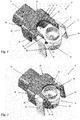
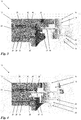
- FIGs 1 and 3 on the one hand and figures 2 and 4 on the other hand illustrate a liquid filtering system 10 according to a preferred embodiment of the invention in its unsecured pre-locking position and in its locking position, respectively.
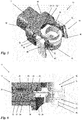
- Figures 5 and 6 finally, illustrate an additional pre-locking position, namely a secured pre-locking position.
- the system shown comprises a base 12 and a filtering apparatus of which, for the sake of clarity, only its adapter 14 is shown.
- the adapter 14 comprises an upper interface 16 to be connected with a filter unit (not shown), especially a filter funnel, to hold a filter layer and to receive the liquid to be filtered.
- the adapter 14 also comprises a lower interface 18 to be screwed, by means of a thread 20 to the neck of a receptacle (not shown), especially a bottle, to receive filtered liquid from the filter unit.
- the adapter 14 comprises an adapter vacuum receiving port 22, which may be coupled to a vacuum source in order to apply a low pressure in the receptacle inducing a vacuum driving force to drive the liquid to be filtered through the filter layer and - as filtered liquid - into the receptacle.
- the adapter vacuum receiving port 22 is connected to the lower interface 18 of the adapter 14.
- the adapter vacuum receiving port 22 comprises a pipe socket 24 extending perpendicular to the liquid flow direction through the adapter 14 and constituting a third interface of the adapter 14.
- the base 12 comprises a cradle 26 to receive the adapter 14 and a base vacuum delivery port 28 to be coupled to the adapter vacuum receiving port 22.
- Said base vacuum delivery port 28 comprises a vacuum valve 30 essentially consisting of a vacuum channel 32, a valve body 34 and a valve seat 36 against which the valve body 34 is sealingly pressed by means of a spring 38.
- the vacuum valve 30 may, on its end averted to the adapter 14, be connected to the vacuum source, especially by means of a central vacuum conduct (not shown) inside a central base holder (not shown) to which the base is fixed, especially as one of a multitude of bases.
- the force of the spring 38 is directed towards the adapter 14, i.e. it is a reset force closing the vacuum valve 30 against the suction of the vacuum source.
- the pipe socket 24 When coupling the adapter 14 to the cradle 26 in the (unsecured) pre-locking position ( figs. 1 and 3 ) the pipe socket 24 is not or only exiguously inserted into the base vacuum delivery port 28 as can be seen in fig. 3 .
- the pipe socket 24 When being transferred to the locking position ( figs. 2 and 4 ) the pipe socket 24 further intrudes into the base vacuum delivery port 28 dislocating the valve body 34 from the valve seat 36 against the force of the spring 38 as can be seen in fig. 4 . In this position air can, in principle, be sucked from the filtering apparatus, especially from its receptacle, through the pipe socket 24 and the open vacuum valve 30 to the vacuum source.
- the spring 38 resets the valve body 34 to its closing state.
- valve body 34 as well as the pipe socket 24 usually are of circular shape there is the danger that the valve body 34 obstructs the exit of the pipe socket 24.
- the embodiment shown in the drawings provides a pipe socket 24 with apertured side walls closed to its valve side end. Air may stream through these apertures 42.
- this sealing ring 44 is of elastomeric material and has walls which are, in a longitudinal section, V-shaped. This facilitates the penetration of the pipe socket 24 and provokes a self-sealing effect according to the so called Bernoulli Effect.
- the locking position is defined by a snap-lock between the adapter 14 and the cradle 26.
- the adapter 14 is provided with two opposed, resiliently pivotable levers 46.
- the upper rims of these levers 46 provide an adapter guiding rail 48 interacting with a corresponding base guiding rail 50 on the side rims of the cradle 26.
- These guiding rails 48, 50 provide for a guided transfer of the adapter 14 from the pre-locking position ( figs. 1 and 3 ) to the locking position ( fig. 2 and 4 ).
- the levers 46 are, at their upper rims, provided with projections 52. In the unsecured pre-locking position these projections are free from corresponding projections 54 on the base guiding rails 50.
- the embodiment shown comprises two different pre-locking positions, namely the unsecured pre-locking position of figures 1 and 3 and the secured pre-locking position of figures 5 and 6 .
- the upper rim of the lever 46 is provided with not only the protrusion 52 but also with an additional protrusion 53 equally suitable to establish a snap-lock connection when interacting with the corresponding protrusions 54 on the rim of the cradle 26.
- no vacuum connection between the base vacuum delivery port 28 and the adapter vacuum receiving port 22 is established as can be easily seen from figure 6 .
- this secured pre-locking position is the preferred "waiting position" for prepared filtering apparatuses waiting to be connected to the vacuum to start the filtering process.
- the levers 46 may be manually, preferredly single-handed, pivoted to disengage the projections 52, 54. Then, the reset force of the spring 38 supports the transfer of the adapter 14 from its locking position into the direction of its pre-locking position while simultaneously closing the vacuum valve 30. By keeping the levers 46 pivoted the operator may overrun the secured pre-locking position and detach the filtering apparatus completely. Alternatively he or she may release the levers 46 in order to have filtering apparatus snapped in the secured pre-locking position, e.g. to temporarily interrupt the filtering process.
Landscapes
- Chemical & Material Sciences (AREA)
- Chemical Kinetics & Catalysis (AREA)
- Filtration Of Liquid (AREA)
- Sampling And Sample Adjustment (AREA)
- Check Valves (AREA)
- Filtering Of Dispersed Particles In Gases (AREA)
- Separation Using Semi-Permeable Membranes (AREA)
Abstract
Description
- The invention relates to a liquid filtering system comprising:
- a filtering apparatus having a filter unit for holding a filter and for receiving liquid to be filtered, a receptacle for receiving filtered liquid, and an adapter for coupling said filter unit to said receptacle,
wherein said adapter comprises an adapter vacuum receiving port to be coupled to a vacuum delivery port in order to apply a vacuum driving force for driving said liquid to be filtered through said filter and - as filtered liquid - into said receptacle, and - a base having a cradle for receiving said filtering apparatus and a base vacuum delivery port to be coupled, on one side, to a vacuum source and, on the other side, to a vacuum receiving port,
- Liquid filtering systems of said kind are known from
WO 2007/028157 A1 . - That document discloses a liquid filtering system with a filtering apparatus essentially consisting of a bottle on top of which a filter funnel is fixed by means of an adapter. On the bottom of said filter funnel there is a filter layer through which a liquid filled into the funnel is filtered and output into the bottle. In order to apply a driving force to drive the liquid through the filter layer into the bottle said bottle is coupled to a vacuum source wherein the according vacuum receiving port is part of said adapter. Said adapter vacuum receiving port essentially is a vertically directed, downward-facing hole constituting the end of an internal conduct. A corresponding upward-facing hole constituting the end of a connection conduct to the vacuum source is located on the rim of a cradle held by a base stand. When the filtering apparatus is positioned in said cradle the two corresponding holes become superimposed, pure gravity establishing a sealed vacuum connection. The stand contains a vacuum valve coupled to said vacuum connection conduct to turn the vacuum on and off.
- Disadvantageously, the prior art liquid filtering system is easy to be maloperated. Especially the sealed vacuum connection is quite instable. Also, after having positioned the filtering apparatus in the cradle the vacuum has to be turned on and it has to be turned off after the filtering process has finished, both in separate steps which is time consuming and likely to be accidently omitted.
- The problem to be solved by the invention is to provide a liquid filtering system easier to handle and better protected against maloperation.
- The above mentioned problem is solved by a liquid filtering system according to claim 1, especially by a liquid filtering system having the features of the generic part of claim 1 and being characterized in that said base vacuum delivery port comprises a vacuum valve constituted as a mechanical normally-closed valve automatically forced open when said filtering apparatus is locked to said cradle.
- Preferred embodiments of the invention are addressed by the dependent claims.
- According to the invention the principal vacuum valve is not a manually operable valve but a valve that is normally, i.e. whenever the filtering apparatus is not located in the cradle, in its closed state. This function is realized purely mechanically. For example, said vacuum valve may comprise a vacuum channel, a valve body being coaxially dislocatable within said vacuum channel, and a valve seat against which said valve body is sealingly pressed by according spring means. On the other hand, the filtering apparatus, especially its adapter comprises a structure that automatically opens said vacuum valve when the filtering apparatus is locked to the cradle. For example, the adapter may comprise a stiff pipe socket that is introduced into said vacuum channel when the adapter is locked to the cradle. The pipe socket gets into contact with the valve body and dislocates it within the vacuum channel opening the vacuum valve. As soon as the filtering apparatus is removed from the cradle the vacuum valve closes again. This makes the whole system not only safe against maloperation but also saves operation time and, thus, renders increases the system more efficient.
- In a preferred embodiment said adapter vacuum receiving port comprises, as exemplarily mentioned above, a stiff pipe socket which, in said locking position, extends through a base port opening of said base vacuum delivery port, dislocating a valve body of said vacuum valve from its closing position to its opening position. Especially, said pipe socket may dislocate said valve body against a reset force of a spring applying a closing force to said valve body. Said reset force has to be stronger than the vacuum force exercised by the vacuum source in order to prevent the valve to be sucked open by the vacuum.
- In terms of a practical construction said vacuum valve may comprise:
- a vacuum channel ending at said base port opening,
- said valve body being coaxially dislocatable within said vacuum channel, and
- a valve seat against which said valve body is sealingly pressed when in said closing position,
- In order to establish a sealed vacuum connection between the base vacuum delivery port and the adapter vacuum receiving port said base vacuum delivery port may comprise a vacuum sealing ring between said base port opening and said vacuum valve, said sealing ring, in said locking position, being sealingly penetrated by said pipe socket.
- In a preferred embodiment said sealing ring is an elastomeric ring having a first axial end, a second axial end, and a central sector located axially between said first and second axial ends, wherein its clear diameter at said first and second ends is larger than the outer diameter of said pipe socket, and wherein its clear diameter at said central sector is as large as or smaller than the outer diameter of said pipe socket. In other words, in a longitudinal section the wall of said sealing ring is V-shaped. This shape implies two advantages. On the one hand, the slope closer to the base port opening facilitates the penetration of the pipe socket. On the other hand, the slope closer to valve provides a self-sealing effect on the basis of the so called Bernoulli Effect: A stream of air through an axially diminishing gap between two walls relatively movable to each other forces said walls to further approach each other and finally close said gap. Air may stream between the vacuum channel and the interior of the pipe socket through said openings.
- Usually the valve body has the shape of a ball. Also, usually the pipe socket has a round profile. If a rectangularly cut, round-profiled pipe socket coaxially hits a ball-shaped valve body said valve body obstructs the entrance of said pipe socket running counter to the goal of opening the valve. Thus, in a preferred embodiment the side wall of said pipe socket may comprise at least one aperture located, in said locking position, axially between said valve body and said sealing ring.
- Especially in the above mentioned preferred embodiment wherein the pipe socket is used to dislocate the valve body against some reset force it is advantageous if said locking means of said adapter and said cradle constitute a detachable snap-lock: the locking process takes place automatically as soon as the filtering apparatus is inserted into its locking position. Thus, a single-handed operation is possible.
- Said detachable snap-lock may comprise two mutually opposing, resiliently pivotable, dented levers, projections of which, in said locking position, engaging behind corresponding projections of said cradle. During insertion of the filtering apparatus into the locking position said projections of said levers on the one hand and said corresponding projections of the cradle on the other hand collide thereby inducing a pivoting of said levers, i.e. an opening of said snap-lock. As soon as the filtering apparatus is finally positioned in its locking position, i.e. as soon as said projections can engage behind said corresponding projections, the levers snap back locking the filtering apparatus to the cradle so that even said (preferredly spring-generated) reset force of the valve body can no longer dislocate the filtering apparatus from its locking position.
- To facilitate even more the process of locking the filtering apparatus to the cradle said cradle may provide two receiving positions for said filtering apparatus, namely said locking position and a pre-locking position, in said pre-locking position said locking means being unlocked and said filtering apparatus being transferable to said locking position by its manually forced, transversal shifting movement guided by mutually interacting guiding means of said adapter and said cradle. Thus, the filtering apparatus can be placed in the cradle without connection to the vacuum source. Especially, if a multitude of filtering processes are to be performed simultaneously a multitude of filtering apparatuses can be placed in a corresponding multitude of cradles in a preparing step without connection them to the vacuum source, i.e. without starting the filtering process. However, the mutual guiding means, e.g. corresponding guiding rails, may engage. Then, by a pure transversal movement which can easily be carried out single-handed, the filtering apparatus may be transferred to its locking position implying a connection to the vacuum source, i.e. starting the filtering process.
- It is even more preferred, if said pre-locking position also provides some (additional) locking means of its own, especially an additional snap-lock, to provide a position, where the filtering apparatus is locked to the cradle without having established the vacuum connection. This position may be addressed as a secured pre-locking position. In other words, it is preferred, if said cradle provides a secured pre-locking position, in said secured pre-locking position additional locking means being locked to lock said filtering apparatus to said cradle without sealingly coupling said base vacuum delivery port to said adapter vacuum receiving port. Said additional locking means may partially use the same constructive features, e.g. certain protrusion of the cradle and/or the adapter, or may be extensions of the above mentioned locking means. Alternatively, they may be constructively separate. It is possible (and even preferred) if two pre-locking positions are provided, namely said secured pre-locking position and an unsecured pre-locking position with no locking means interacting. If the pre-locking position provides locking means of its own, i.e. if the (or one) pre-locking position is a secured pre-locking position, the filtering apparatus is safely secured, especially against being tipped over, in a position, where the vacuum connection is not yet established. Thus, establishing the vacuum connection and securing the filtering apparatus to the base become more independent from each another.
- Said pipe socket may contain a preferably sterile gas filter. On the one hand, such filter may prevent contaminations (which might be hidden in the base vacuum delivery port) from entering the filtering apparatus. On the other hand, such filter may prevent foam generated in the filtering apparatus, especially in the receptacle, from reaching the vacuum valve and from being sucked to the vacuum generating system. Especially in view of the latter effect said gas filter preferably is a hydrophobic gas filter.
- For safety reasons and especially to avoid foam building said base may comprise an additional vacuum valve being manually switchable between an opening state and a closing state as, in principle, known from prior art. Said switchability may comprise a simple on/of-mechanism but may, alternatively, also comprise a mechanism for precisely controlling the vacuum strength. In view of the specific position of said additional vacuum valve one skilled in the art has the choice between different options. For example, the additional vacuum valve may be positioned within the cradle. Alternatively it may be positioned within a central base holder (see below).
- Often, it is intended to perform several filtering processes more or less simultaneously. A preferred embodiment of the invention provides such function in a particularly space-saving manner. In this embodiment said base makes part of a multitude of identical bases each of them being fixed to a central base holder having a central vacuum conduct being connected to the base vacuum delivery port of each one of said multitude of bases.
- Said central base holder may be a rotatable stand having a central post containing said central vacuum conduct, said multitude of bases extending radially from said post exhibiting their cradles radially outwardly. Thus, the central base holder and the bases make up a carousel into which the filtering apparatuses may be clipped one after the other is a very fast sequence.
- Further features and advantages of the invention may be better understood from the following specific description as well as from the drawings attached.
-
- figure 1:
- a perspective view of a liquid filtering system according to the invention in its (unsecured) pre-locking position, wherein of its filtering apparatus only the adapter is shown;
- figure 2:
- a perspective view of the liquid filtering system of
figure 1 in its locking position; - figure 3:
- a longitudinal section of the liquid filtering system of
figure 1 ; - figure 4:
- a longitudinal section of the liquid filtering system of
figure 2 ; - figure 5:
- a perspective view of a liquid filtering system according to the invention in its secured pre-locking position, wherein of its filtering apparatus only the adapter is shown and
- figure 6:
- a longitudinal section of the liquid filtering system of
figure 5 . - In the drawings, like reference numerals designate like items.
-
Figures 1 and3 on the one hand andfigures 2 and4 on the other hand illustrate aliquid filtering system 10 according to a preferred embodiment of the invention in its unsecured pre-locking position and in its locking position, respectively.Figures 5 and 6 , finally, illustrate an additional pre-locking position, namely a secured pre-locking position. As far as possible said figures are to be discussed together in the following. - The system shown comprises a
base 12 and a filtering apparatus of which, for the sake of clarity, only itsadapter 14 is shown. Theadapter 14 comprises anupper interface 16 to be connected with a filter unit (not shown), especially a filter funnel, to hold a filter layer and to receive the liquid to be filtered. Theadapter 14 also comprises alower interface 18 to be screwed, by means of athread 20 to the neck of a receptacle (not shown), especially a bottle, to receive filtered liquid from the filter unit. - Finally the
adapter 14 comprises an adaptervacuum receiving port 22, which may be coupled to a vacuum source in order to apply a low pressure in the receptacle inducing a vacuum driving force to drive the liquid to be filtered through the filter layer and - as filtered liquid - into the receptacle. Thus, the adaptervacuum receiving port 22 is connected to thelower interface 18 of theadapter 14. The adaptervacuum receiving port 22 comprises apipe socket 24 extending perpendicular to the liquid flow direction through theadapter 14 and constituting a third interface of theadapter 14. - The
base 12 comprises acradle 26 to receive theadapter 14 and a basevacuum delivery port 28 to be coupled to the adaptervacuum receiving port 22. Said basevacuum delivery port 28 comprises avacuum valve 30 essentially consisting of avacuum channel 32, avalve body 34 and avalve seat 36 against which thevalve body 34 is sealingly pressed by means of aspring 38. In order to provide a secure vacuum sealing thevalve body 34 is armed with agasket 40 within its contacting area to thevalve seat 36. Thevacuum valve 30 may, on its end averted to theadapter 14, be connected to the vacuum source, especially by means of a central vacuum conduct (not shown) inside a central base holder (not shown) to which the base is fixed, especially as one of a multitude of bases. The force of thespring 38 is directed towards theadapter 14, i.e. it is a reset force closing thevacuum valve 30 against the suction of the vacuum source. - When coupling the
adapter 14 to thecradle 26 in the (unsecured) pre-locking position (figs. 1 and3 ) thepipe socket 24 is not or only exiguously inserted into the basevacuum delivery port 28 as can be seen infig. 3 . When being transferred to the locking position (figs. 2 and4 ) thepipe socket 24 further intrudes into the basevacuum delivery port 28 dislocating thevalve body 34 from thevalve seat 36 against the force of thespring 38 as can be seen infig. 4 . In this position air can, in principle, be sucked from the filtering apparatus, especially from its receptacle, through thepipe socket 24 and theopen vacuum valve 30 to the vacuum source. When theadapter 14 is removed from the locking position thespring 38 resets thevalve body 34 to its closing state. - However, since the
valve body 34 as well as thepipe socket 24 usually are of circular shape there is the danger that thevalve body 34 obstructs the exit of thepipe socket 24. Thus, the embodiment shown in the drawings provides apipe socket 24 with apertured side walls closed to its valve side end. Air may stream through theseapertures 42. - In order to provide a sealed connection of the adapter
vacuum receiving port 22 to the basevacuum delivery port 28 thepipe socket 24 penetrates a sealingring 44. In the embodiment shown in the drawings this sealingring 44 is of elastomeric material and has walls which are, in a longitudinal section, V-shaped. This facilitates the penetration of thepipe socket 24 and provokes a self-sealing effect according to the so called Bernoulli Effect. - In the embodiment shown in the drawings the locking position is defined by a snap-lock between the
adapter 14 and thecradle 26. Theadapter 14 is provided with two opposed, resiliently pivotable levers 46. The upper rims of theselevers 46 provide anadapter guiding rail 48 interacting with a correspondingbase guiding rail 50 on the side rims of thecradle 26. These guiding rails 48, 50 provide for a guided transfer of theadapter 14 from the pre-locking position (figs. 1 and3 ) to the locking position (fig. 2 and4 ). Thelevers 46 are, at their upper rims, provided withprojections 52. In the unsecured pre-locking position these projections are free from correspondingprojections 54 on the base guiding rails 50. In the locking position, however, they engage behind each other to effectively lock theadapter 14 to thecradle 26. Due to the resilience of thelevers 46 this locking is effected automatically when transferring theadapter 14 from the pre-locking position to the locking position. This transfer can easily be effected single-handed wherein fingers of the operator may engage behindspecial terraces 56 of thebase 12. - The embodiment shown comprises two different pre-locking positions, namely the unsecured pre-locking position of
figures 1 and3 and the secured pre-locking position offigures 5 and 6 . The upper rim of thelever 46 is provided with not only theprotrusion 52 but also with anadditional protrusion 53 equally suitable to establish a snap-lock connection when interacting with the correspondingprotrusions 54 on the rim of thecradle 26. However, in this position no vacuum connection between the basevacuum delivery port 28 and the adaptervacuum receiving port 22 is established as can be easily seen fromfigure 6 . Thus, in the illustrated embodiment the above mentioned guided transfers of the adapter from the (unsecured) pre-locking position offigures 1 and3 to the locking position offigures 2 and4 takes course via the secured pre-locking position offigures 5 and 6 . In practice, this secured pre-locking position is the preferred "waiting position" for prepared filtering apparatuses waiting to be connected to the vacuum to start the filtering process. - In order to open the snap-lock in the locking position the
levers 46 may be manually, preferredly single-handed, pivoted to disengage theprojections spring 38 supports the transfer of theadapter 14 from its locking position into the direction of its pre-locking position while simultaneously closing thevacuum valve 30. By keeping thelevers 46 pivoted the operator may overrun the secured pre-locking position and detach the filtering apparatus completely. Alternatively he or she may release thelevers 46 in order to have filtering apparatus snapped in the secured pre-locking position, e.g. to temporarily interrupt the filtering process. - Of course, the embodiments as discussed in the specific description and as shown in the drawings are illustrative examples only. In view of the disclosure given here one skilled in the art is enabled to realize a wide spectrum of variations.
-
- 10
- liquid filtering system
- 12
- base
- 14
- adapter
- 16
- upper interface of 14
- 18
- lower interface of 14
- 20
- thread
- 22
- adapter vacuum receiving port
- 24
- pipe socket
- 26
- cradle
- 28
- base vacuum delivery port
- 30
- vacuum valve
- 32
- vacuum channel
- 34
- valve body
- 36
- valve seat
- 38
- spring
- 40
- gasket
- 42
- aperture
- 44
- sealing ring
- 46
- lever
- 48
- adapter guiding rail
- 50
- base guiding rail
- 52
- projection on 46
- 53
- additional projection on 46
- 54
- corresponding projection
- 56
- terrace
Claims (16)
- A liquid filtering system (10) comprising :- a filtering apparatus having a filter unit for holding a filter and for receiving liquid to be filtered, a receptacle for receiving filtered liquid, and an adapter (14) for coupling said filter unit to said receptacle,
wherein said adapter (14) comprises an adapter vacuum receiving port (22) to be coupled to a vacuum delivery port (28) in order to apply a vacuum driving force for driving said liquid to be filtered through said filter and - as filtered liquid - into said receptacle, and- a base (12) having a cradle (26) for receiving said filtering apparatus and a base vacuum delivery port (28) to be coupled, on one side, to a vacuum source and, on the other side, to a vacuum receiving port (22),said cradle (26) and said adapter (14) having locking means (52, 54) interacting to lock said filtering apparatus to said cradle (26) in a locking position in which locking position said adapter vacuum receiving port (22) is sealingly coupled to said base vacuum delivery port (28),
characterized in that
said base vacuum delivery port (28) comprises a vacuum valve (30) constituted as a mechanical normally-closed valve automatically forced open when said filtering apparatus is locked to said cradle (26). - The liquid filtering system (10) according to claim 1,
characterized in that
said adapter vacuum receiving port (22) comprises a stiff pipe socket (24) which, in said locking position, extends through a base port opening of said base vacuum delivery port (28), dislocating a valve body (34) of said vacuum valve (30) from its closing position to its opening position. - The liquid filtering system (10) according to any claim 2,
characterized in that
said pipe socket (24) dislocates said valve body (34) against a reset force of a spring (38) applying a closing force to said valve body (34). - The liquid filtering system (10) according to any one of claims 2 to 3,
characterized in that
said vacuum valve (30) comprises- a vacuum channel (32) ending at said base port opening,- said valve body (34) being coaxially dislocatable within said vacuum channel (32), and- a valve seat (36) against which said valve body (34) is sealingly pressed when in said closing position,wherein said pipe socket (24), in said locking position, extends coaxially into said vacuum channel (32). - The liquid filtering system (10) according to any one of claims 2 to 4,
characterized in that
said base vacuum delivery port (28) comprises a vacuum sealing ring (44) axially between said base port opening and said vacuum valve (30), said sealing ring (44), in said locking position, being sealingly penetrated by said pipe socket (24). - The liquid filtering system (10) according to claim 5,
characterized in that
said sealing ring (44) is an elastomeric ring having a first axial end, a second axial end, and a central sector located axially between said first and second axial ends, wherein its clear diameter at said first and second ends is larger than the outer diameter of said pipe socket (24), and wherein its clear diameter at said central sector is as large as or smaller than the outer diameter of said pipe socket (24). - The liquid filtering system (10) according to claim 4 and any one of claims 5 to 6,
characterized in that
the side wall of said pipe socket (24) comprises at least one aperture (42) located, in said locking position, between said valve body (34) and said sealing ring (44). - The liquid filtering system (10) according to any one of the preceding claims,
characterized in that
said locking means (52, 54) of said adapter (14) and said cradle (26) constitute a detachable snap-lock. - The liquid filtering system (10) according to claim 8,
characterized in that
said detachable snap-lock comprises two mutually opposing, resiliently pivotable, dented levers (46), projections (52) of which, in said locking position, engaging behind corresponding projections (54) of said cradle (26). - The liquid filtering system (10) according to any one of claims 8 to 9,
characterized in that
said cradle (26) provides at least two receiving positions for said filtering apparatus, namely said locking position and at least one pre-locking position,
in said pre-locking position said locking means (52, 54) being unlocked and said filtering apparatus being transferable to said locking position by its manually forced, transversal shifting movement guided by mutually interacting guiding means (48, 50) of said adapter (14) and said cradle (26). - The liquid filtering system (10) according to claim 10,
characterized in that
said cradle (26) provides a secured pre-locking position, in said secured pre-locking position additional locking means (53/54) being locked to lock said filtering apparatus to said cradle (26) without sealingly coupling said base vacuum delivery port (28) to said adapter vacuum receiving port (24). - The liquid filtering system (10) according to any one of claims 2 to 11,
characterized in that
said pipe socket (24) contains a preferably sterile gas filter. - The liquid filtering system (10) according to claim 12,
characterized in that
said gas filter is a hydrophobic gas filter. - The liquid filtering system (10) according to any one of the preceding claims,
characterized in that
said base (12) comprises an additional vacuum valve being manually switchable between an opening state and a closing state. - The liquid filtering system (10) according to any one of the preceding claims,
characterized in that
said base (12) makes part of a multitude of identical bases (12) each of them being fixed to a central base holder having a central vacuum conduct being connected to the base vacuum delivery port (28) of each one of said multitude of bases (12). - The liquid filtering system (10) according to claim 15,
characterized in that
said central base holder is a rotatable stand having a central post containing said central vacuum conduct, said multitude of bases (12) extending radially from said post exhibiting their cradles (26) radially outwardly.
Priority Applications (8)
| Application Number | Priority Date | Filing Date | Title |
|---|---|---|---|
| EP18182730.4A EP3593903B1 (en) | 2018-07-10 | 2018-07-10 | Liquid filtering system with vacuum valve |
| JP2021521887A JP7155418B2 (en) | 2018-07-10 | 2019-05-13 | liquid filtration system |
| CN201980042851.3A CN112313009A (en) | 2018-07-10 | 2019-05-13 | Liquid Filtration System |
| KR1020227042637A KR102513496B1 (en) | 2018-07-10 | 2019-05-13 | Liquid filtering system |
| PCT/EP2019/062214 WO2020011423A1 (en) | 2018-07-10 | 2019-05-13 | Liquid filtering system |
| KR1020217004135A KR102475783B1 (en) | 2018-07-10 | 2019-05-13 | liquid filtering system |
| US17/145,058 US11666840B2 (en) | 2018-07-10 | 2021-01-08 | Liquid filtering system |
| US18/329,773 US12285708B2 (en) | 2018-07-10 | 2023-06-06 | Liquid filtering method and system |
Applications Claiming Priority (1)
| Application Number | Priority Date | Filing Date | Title |
|---|---|---|---|
| EP18182730.4A EP3593903B1 (en) | 2018-07-10 | 2018-07-10 | Liquid filtering system with vacuum valve |
Publications (2)
| Publication Number | Publication Date |
|---|---|
| EP3593903A1 true EP3593903A1 (en) | 2020-01-15 |
| EP3593903B1 EP3593903B1 (en) | 2020-09-02 |
Family
ID=62916464
Family Applications (1)
| Application Number | Title | Priority Date | Filing Date |
|---|---|---|---|
| EP18182730.4A Active EP3593903B1 (en) | 2018-07-10 | 2018-07-10 | Liquid filtering system with vacuum valve |
Country Status (6)
| Country | Link |
|---|---|
| US (2) | US11666840B2 (en) |
| EP (1) | EP3593903B1 (en) |
| JP (1) | JP7155418B2 (en) |
| KR (2) | KR102475783B1 (en) |
| CN (1) | CN112313009A (en) |
| WO (1) | WO2020011423A1 (en) |
Cited By (2)
| Publication number | Priority date | Publication date | Assignee | Title |
|---|---|---|---|---|
| CN113967658A (en) * | 2021-09-27 | 2022-01-25 | 海盐凯达纺织新材料股份有限公司 | Terylene textile secondary recycling treatment device |
| CN115521355A (en) * | 2022-09-28 | 2022-12-27 | 肇庆医学高等专科学校 | Protein purification device and method |
Citations (8)
| Publication number | Priority date | Publication date | Assignee | Title |
|---|---|---|---|---|
| WO2000072970A1 (en) * | 1999-05-28 | 2000-12-07 | Cepheid | Cartridge for conducting a chemical reaction |
| US20020098125A1 (en) * | 2001-01-23 | 2002-07-25 | Roberts Roger Q. | Multi-well filtration apparatus |
| WO2007028157A1 (en) | 2005-09-02 | 2007-03-08 | Zuk Peter Jr | Systems, apparatus and methods for vacuum filtration |
| WO2008144083A1 (en) * | 2007-05-23 | 2008-11-27 | Nypro Inc. | Methods and apparatus for foam control in a vacuum filtration system |
| WO2009014769A1 (en) * | 2007-07-26 | 2009-01-29 | Nypro Inc. | Methods and apparatus for supporting a vacuum filtration device |
| WO2015032464A2 (en) * | 2013-09-05 | 2015-03-12 | Merck Patent Gmbh | Filter device for filtering complex fluid samples |
| EP3056276A2 (en) * | 2015-02-11 | 2016-08-17 | EMD Millipore Corporation | Stirred cell and method of using same |
| WO2016131859A1 (en) * | 2015-02-20 | 2016-08-25 | Ventana Medical Systems, Inc. | Assembly for storing and transporting tissue samples immersed in a fluid |
Family Cites Families (6)
| Publication number | Priority date | Publication date | Assignee | Title |
|---|---|---|---|---|
| JPS55115315U (en) * | 1979-02-02 | 1980-08-14 | ||
| JPH0622577U (en) * | 1991-11-12 | 1994-03-25 | 東芝機械株式会社 | Suction filter |
| KR0175901B1 (en) * | 1996-05-17 | 1999-03-20 | 김광호 | Cold and hot water purifier |
| CN201651485U (en) * | 2010-03-19 | 2010-11-24 | 平高集团有限公司 | An oil discharge valve and an oil filling and discharging tool |
| US20120180577A1 (en) * | 2011-01-13 | 2012-07-19 | Pall Corporation | Peristaltic pumps and filtration assembly systems for use therewith |
| KR101533888B1 (en) * | 2013-11-14 | 2015-07-03 | 도레이케미칼 주식회사 | Carriage with supporting device for assemblying filter sump and filter assembly using thereof |
-
2018
- 2018-07-10 EP EP18182730.4A patent/EP3593903B1/en active Active
-
2019
- 2019-05-13 KR KR1020217004135A patent/KR102475783B1/en active Active
- 2019-05-13 JP JP2021521887A patent/JP7155418B2/en active Active
- 2019-05-13 KR KR1020227042637A patent/KR102513496B1/en active Active
- 2019-05-13 WO PCT/EP2019/062214 patent/WO2020011423A1/en not_active Ceased
- 2019-05-13 CN CN201980042851.3A patent/CN112313009A/en active Pending
-
2021
- 2021-01-08 US US17/145,058 patent/US11666840B2/en active Active
-
2023
- 2023-06-06 US US18/329,773 patent/US12285708B2/en active Active
Patent Citations (8)
| Publication number | Priority date | Publication date | Assignee | Title |
|---|---|---|---|---|
| WO2000072970A1 (en) * | 1999-05-28 | 2000-12-07 | Cepheid | Cartridge for conducting a chemical reaction |
| US20020098125A1 (en) * | 2001-01-23 | 2002-07-25 | Roberts Roger Q. | Multi-well filtration apparatus |
| WO2007028157A1 (en) | 2005-09-02 | 2007-03-08 | Zuk Peter Jr | Systems, apparatus and methods for vacuum filtration |
| WO2008144083A1 (en) * | 2007-05-23 | 2008-11-27 | Nypro Inc. | Methods and apparatus for foam control in a vacuum filtration system |
| WO2009014769A1 (en) * | 2007-07-26 | 2009-01-29 | Nypro Inc. | Methods and apparatus for supporting a vacuum filtration device |
| WO2015032464A2 (en) * | 2013-09-05 | 2015-03-12 | Merck Patent Gmbh | Filter device for filtering complex fluid samples |
| EP3056276A2 (en) * | 2015-02-11 | 2016-08-17 | EMD Millipore Corporation | Stirred cell and method of using same |
| WO2016131859A1 (en) * | 2015-02-20 | 2016-08-25 | Ventana Medical Systems, Inc. | Assembly for storing and transporting tissue samples immersed in a fluid |
Cited By (2)
| Publication number | Priority date | Publication date | Assignee | Title |
|---|---|---|---|---|
| CN113967658A (en) * | 2021-09-27 | 2022-01-25 | 海盐凯达纺织新材料股份有限公司 | Terylene textile secondary recycling treatment device |
| CN115521355A (en) * | 2022-09-28 | 2022-12-27 | 肇庆医学高等专科学校 | Protein purification device and method |
Also Published As
| Publication number | Publication date |
|---|---|
| WO2020011423A1 (en) | 2020-01-16 |
| EP3593903B1 (en) | 2020-09-02 |
| US12285708B2 (en) | 2025-04-29 |
| US20230311035A1 (en) | 2023-10-05 |
| KR102513496B1 (en) | 2023-03-23 |
| KR102475783B1 (en) | 2022-12-08 |
| KR20220165839A (en) | 2022-12-15 |
| JP7155418B2 (en) | 2022-10-18 |
| US20210129057A1 (en) | 2021-05-06 |
| US11666840B2 (en) | 2023-06-06 |
| JP2021529090A (en) | 2021-10-28 |
| CN112313009A (en) | 2021-02-02 |
| KR20210032991A (en) | 2021-03-25 |
Similar Documents
| Publication | Publication Date | Title |
|---|---|---|
| US8967412B2 (en) | Drinking cup with lid and flow control element | |
| JP2712115B2 (en) | Quick-fit fuel cap | |
| EP0998644B1 (en) | Connector assembly for a fluid connection | |
| CA2272552C (en) | Non-leaking, non-venting liquid filled canister quick disconnect system | |
| US9963279B2 (en) | Container for transporting and storing a liquid | |
| US12285708B2 (en) | Liquid filtering method and system | |
| MXPA06009134A (en) | Quick connect coupling. | |
| JPH10505811A (en) | Liquid container valve structure used for service line connector | |
| JP5647097B2 (en) | Beverage dispenser | |
| US20180079564A1 (en) | Dispensing assembly | |
| US20120261375A1 (en) | Drinking Cup with Lid and Flow Control Element | |
| MX2008015126A (en) | Child resistant concentrate cartridge and associated diluting and dispensing container. | |
| JP2002509061A (en) | Air passage built-in tap | |
| JP2003525113A (en) | Disposable fluid separator with easy replacement-manifold assembly design | |
| CA2920716A1 (en) | A container for transporting and storing a liquid | |
| US20230310277A1 (en) | Vial adaptor with valve | |
| US11691863B2 (en) | Vented funnel with fluid flow stopper | |
| JP2019509088A (en) | Powder chamber and station for powder chamber | |
| KR20030022225A (en) | Beverage discharging valve | |
| EP1407979B1 (en) | Closing device, with funnel function, for containers of liquid | |
| CA2790761A1 (en) | Drinking cup with lid and flow control element | |
| AU2002301377B2 (en) | Connector assembly for a fluid connection | |
| CA2722493A1 (en) | Drinking cup with lid and flow control element |
Legal Events
| Date | Code | Title | Description |
|---|---|---|---|
| STAA | Information on the status of an ep patent application or granted ep patent |
Free format text: STATUS: EXAMINATION IS IN PROGRESS |
|
| PUAI | Public reference made under article 153(3) epc to a published international application that has entered the european phase |
Free format text: ORIGINAL CODE: 0009012 |
|
| 17P | Request for examination filed |
Effective date: 20190311 |
|
| AK | Designated contracting states |
Kind code of ref document: A1 Designated state(s): AL AT BE BG CH CY CZ DE DK EE ES FI FR GB GR HR HU IE IS IT LI LT LU LV MC MK MT NL NO PL PT RO RS SE SI SK SM TR |
|
| AX | Request for extension of the european patent |
Extension state: BA ME |
|
| REG | Reference to a national code |
Ref country code: DE Ref legal event code: R079 Ref document number: 602018007410 Country of ref document: DE Free format text: PREVIOUS MAIN CLASS: B01L0003000000 Ipc: B01D0037000000 |
|
| GRAP | Despatch of communication of intention to grant a patent |
Free format text: ORIGINAL CODE: EPIDOSNIGR1 |
|
| STAA | Information on the status of an ep patent application or granted ep patent |
Free format text: STATUS: GRANT OF PATENT IS INTENDED |
|
| RIC1 | Information provided on ipc code assigned before grant |
Ipc: B01D 37/00 20060101AFI20200318BHEP Ipc: B01D 35/30 20060101ALI20200318BHEP |
|
| INTG | Intention to grant announced |
Effective date: 20200330 |
|
| GRAS | Grant fee paid |
Free format text: ORIGINAL CODE: EPIDOSNIGR3 |
|
| GRAA | (expected) grant |
Free format text: ORIGINAL CODE: 0009210 |
|
| STAA | Information on the status of an ep patent application or granted ep patent |
Free format text: STATUS: THE PATENT HAS BEEN GRANTED |
|
| AK | Designated contracting states |
Kind code of ref document: B1 Designated state(s): AL AT BE BG CH CY CZ DE DK EE ES FI FR GB GR HR HU IE IS IT LI LT LU LV MC MK MT NL NO PL PT RO RS SE SI SK SM TR |
|
| REG | Reference to a national code |
Ref country code: GB Ref legal event code: FG4D |
|
| REG | Reference to a national code |
Ref country code: AT Ref legal event code: REF Ref document number: 1308158 Country of ref document: AT Kind code of ref document: T Effective date: 20200915 Ref country code: CH Ref legal event code: EP |
|
| REG | Reference to a national code |
Ref country code: DE Ref legal event code: R096 Ref document number: 602018007410 Country of ref document: DE |
|
| REG | Reference to a national code |
Ref country code: IE Ref legal event code: FG4D |
|
| REG | Reference to a national code |
Ref country code: LT Ref legal event code: MG4D |
|
| PG25 | Lapsed in a contracting state [announced via postgrant information from national office to epo] |
Ref country code: SE Free format text: LAPSE BECAUSE OF FAILURE TO SUBMIT A TRANSLATION OF THE DESCRIPTION OR TO PAY THE FEE WITHIN THE PRESCRIBED TIME-LIMIT Effective date: 20200902 Ref country code: BG Free format text: LAPSE BECAUSE OF FAILURE TO SUBMIT A TRANSLATION OF THE DESCRIPTION OR TO PAY THE FEE WITHIN THE PRESCRIBED TIME-LIMIT Effective date: 20201202 Ref country code: HR Free format text: LAPSE BECAUSE OF FAILURE TO SUBMIT A TRANSLATION OF THE DESCRIPTION OR TO PAY THE FEE WITHIN THE PRESCRIBED TIME-LIMIT Effective date: 20200902 Ref country code: GR Free format text: LAPSE BECAUSE OF FAILURE TO SUBMIT A TRANSLATION OF THE DESCRIPTION OR TO PAY THE FEE WITHIN THE PRESCRIBED TIME-LIMIT Effective date: 20201203 Ref country code: NO Free format text: LAPSE BECAUSE OF FAILURE TO SUBMIT A TRANSLATION OF THE DESCRIPTION OR TO PAY THE FEE WITHIN THE PRESCRIBED TIME-LIMIT Effective date: 20201202 Ref country code: LT Free format text: LAPSE BECAUSE OF FAILURE TO SUBMIT A TRANSLATION OF THE DESCRIPTION OR TO PAY THE FEE WITHIN THE PRESCRIBED TIME-LIMIT Effective date: 20200902 Ref country code: FI Free format text: LAPSE BECAUSE OF FAILURE TO SUBMIT A TRANSLATION OF THE DESCRIPTION OR TO PAY THE FEE WITHIN THE PRESCRIBED TIME-LIMIT Effective date: 20200902 |
|
| REG | Reference to a national code |
Ref country code: NL Ref legal event code: MP Effective date: 20200902 |
|
| REG | Reference to a national code |
Ref country code: AT Ref legal event code: MK05 Ref document number: 1308158 Country of ref document: AT Kind code of ref document: T Effective date: 20200902 |
|
| PG25 | Lapsed in a contracting state [announced via postgrant information from national office to epo] |
Ref country code: LV Free format text: LAPSE BECAUSE OF FAILURE TO SUBMIT A TRANSLATION OF THE DESCRIPTION OR TO PAY THE FEE WITHIN THE PRESCRIBED TIME-LIMIT Effective date: 20200902 Ref country code: RS Free format text: LAPSE BECAUSE OF FAILURE TO SUBMIT A TRANSLATION OF THE DESCRIPTION OR TO PAY THE FEE WITHIN THE PRESCRIBED TIME-LIMIT Effective date: 20200902 Ref country code: PL Free format text: LAPSE BECAUSE OF FAILURE TO SUBMIT A TRANSLATION OF THE DESCRIPTION OR TO PAY THE FEE WITHIN THE PRESCRIBED TIME-LIMIT Effective date: 20200902 |
|
| PG25 | Lapsed in a contracting state [announced via postgrant information from national office to epo] |
Ref country code: SM Free format text: LAPSE BECAUSE OF FAILURE TO SUBMIT A TRANSLATION OF THE DESCRIPTION OR TO PAY THE FEE WITHIN THE PRESCRIBED TIME-LIMIT Effective date: 20200902 Ref country code: EE Free format text: LAPSE BECAUSE OF FAILURE TO SUBMIT A TRANSLATION OF THE DESCRIPTION OR TO PAY THE FEE WITHIN THE PRESCRIBED TIME-LIMIT Effective date: 20200902 Ref country code: RO Free format text: LAPSE BECAUSE OF FAILURE TO SUBMIT A TRANSLATION OF THE DESCRIPTION OR TO PAY THE FEE WITHIN THE PRESCRIBED TIME-LIMIT Effective date: 20200902 Ref country code: PT Free format text: LAPSE BECAUSE OF FAILURE TO SUBMIT A TRANSLATION OF THE DESCRIPTION OR TO PAY THE FEE WITHIN THE PRESCRIBED TIME-LIMIT Effective date: 20210104 Ref country code: CZ Free format text: LAPSE BECAUSE OF FAILURE TO SUBMIT A TRANSLATION OF THE DESCRIPTION OR TO PAY THE FEE WITHIN THE PRESCRIBED TIME-LIMIT Effective date: 20200902 |
|
| PG25 | Lapsed in a contracting state [announced via postgrant information from national office to epo] |
Ref country code: IS Free format text: LAPSE BECAUSE OF FAILURE TO SUBMIT A TRANSLATION OF THE DESCRIPTION OR TO PAY THE FEE WITHIN THE PRESCRIBED TIME-LIMIT Effective date: 20210102 Ref country code: AL Free format text: LAPSE BECAUSE OF FAILURE TO SUBMIT A TRANSLATION OF THE DESCRIPTION OR TO PAY THE FEE WITHIN THE PRESCRIBED TIME-LIMIT Effective date: 20200902 Ref country code: AT Free format text: LAPSE BECAUSE OF FAILURE TO SUBMIT A TRANSLATION OF THE DESCRIPTION OR TO PAY THE FEE WITHIN THE PRESCRIBED TIME-LIMIT Effective date: 20200902 Ref country code: ES Free format text: LAPSE BECAUSE OF FAILURE TO SUBMIT A TRANSLATION OF THE DESCRIPTION OR TO PAY THE FEE WITHIN THE PRESCRIBED TIME-LIMIT Effective date: 20200902 |
|
| REG | Reference to a national code |
Ref country code: DE Ref legal event code: R097 Ref document number: 602018007410 Country of ref document: DE |
|
| PG25 | Lapsed in a contracting state [announced via postgrant information from national office to epo] |
Ref country code: SK Free format text: LAPSE BECAUSE OF FAILURE TO SUBMIT A TRANSLATION OF THE DESCRIPTION OR TO PAY THE FEE WITHIN THE PRESCRIBED TIME-LIMIT Effective date: 20200902 |
|
| PLBE | No opposition filed within time limit |
Free format text: ORIGINAL CODE: 0009261 |
|
| STAA | Information on the status of an ep patent application or granted ep patent |
Free format text: STATUS: NO OPPOSITION FILED WITHIN TIME LIMIT |
|
| 26N | No opposition filed |
Effective date: 20210603 |
|
| PG25 | Lapsed in a contracting state [announced via postgrant information from national office to epo] |
Ref country code: DK Free format text: LAPSE BECAUSE OF FAILURE TO SUBMIT A TRANSLATION OF THE DESCRIPTION OR TO PAY THE FEE WITHIN THE PRESCRIBED TIME-LIMIT Effective date: 20200902 |
|
| REG | Reference to a national code |
Ref country code: CH Ref legal event code: PL |
|
| PG25 | Lapsed in a contracting state [announced via postgrant information from national office to epo] |
Ref country code: MC Free format text: LAPSE BECAUSE OF FAILURE TO SUBMIT A TRANSLATION OF THE DESCRIPTION OR TO PAY THE FEE WITHIN THE PRESCRIBED TIME-LIMIT Effective date: 20200902 |
|
| REG | Reference to a national code |
Ref country code: BE Ref legal event code: MM Effective date: 20210731 |
|
| PG25 | Lapsed in a contracting state [announced via postgrant information from national office to epo] |
Ref country code: LI Free format text: LAPSE BECAUSE OF NON-PAYMENT OF DUE FEES Effective date: 20210731 Ref country code: CH Free format text: LAPSE BECAUSE OF NON-PAYMENT OF DUE FEES Effective date: 20210731 |
|
| PG25 | Lapsed in a contracting state [announced via postgrant information from national office to epo] |
Ref country code: LU Free format text: LAPSE BECAUSE OF NON-PAYMENT OF DUE FEES Effective date: 20210710 |
|
| PG25 | Lapsed in a contracting state [announced via postgrant information from national office to epo] |
Ref country code: IE Free format text: LAPSE BECAUSE OF NON-PAYMENT OF DUE FEES Effective date: 20210710 Ref country code: BE Free format text: LAPSE BECAUSE OF NON-PAYMENT OF DUE FEES Effective date: 20210731 |
|
| PG25 | Lapsed in a contracting state [announced via postgrant information from national office to epo] |
Ref country code: NL Free format text: LAPSE BECAUSE OF NON-PAYMENT OF DUE FEES Effective date: 20200923 Ref country code: CY Free format text: LAPSE BECAUSE OF FAILURE TO SUBMIT A TRANSLATION OF THE DESCRIPTION OR TO PAY THE FEE WITHIN THE PRESCRIBED TIME-LIMIT Effective date: 20200902 |
|
| P01 | Opt-out of the competence of the unified patent court (upc) registered |
Effective date: 20230526 |
|
| PG25 | Lapsed in a contracting state [announced via postgrant information from national office to epo] |
Ref country code: HU Free format text: LAPSE BECAUSE OF FAILURE TO SUBMIT A TRANSLATION OF THE DESCRIPTION OR TO PAY THE FEE WITHIN THE PRESCRIBED TIME-LIMIT; INVALID AB INITIO Effective date: 20180710 |
|
| PG25 | Lapsed in a contracting state [announced via postgrant information from national office to epo] |
Ref country code: SI Free format text: LAPSE BECAUSE OF FAILURE TO SUBMIT A TRANSLATION OF THE DESCRIPTION OR TO PAY THE FEE WITHIN THE PRESCRIBED TIME-LIMIT Effective date: 20200902 |
|
| PG25 | Lapsed in a contracting state [announced via postgrant information from national office to epo] |
Ref country code: MK Free format text: LAPSE BECAUSE OF FAILURE TO SUBMIT A TRANSLATION OF THE DESCRIPTION OR TO PAY THE FEE WITHIN THE PRESCRIBED TIME-LIMIT Effective date: 20200902 |
|
| PG25 | Lapsed in a contracting state [announced via postgrant information from national office to epo] |
Ref country code: MT Free format text: LAPSE BECAUSE OF FAILURE TO SUBMIT A TRANSLATION OF THE DESCRIPTION OR TO PAY THE FEE WITHIN THE PRESCRIBED TIME-LIMIT Effective date: 20200902 |
|
| PGFP | Annual fee paid to national office [announced via postgrant information from national office to epo] |
Ref country code: DE Payment date: 20250722 Year of fee payment: 8 |
|
| PGFP | Annual fee paid to national office [announced via postgrant information from national office to epo] |
Ref country code: IT Payment date: 20250731 Year of fee payment: 8 |
|
| PGFP | Annual fee paid to national office [announced via postgrant information from national office to epo] |
Ref country code: GB Payment date: 20250724 Year of fee payment: 8 |
|
| PGFP | Annual fee paid to national office [announced via postgrant information from national office to epo] |
Ref country code: FR Payment date: 20250723 Year of fee payment: 8 |
|
| PG25 | Lapsed in a contracting state [announced via postgrant information from national office to epo] |
Ref country code: TR Free format text: LAPSE BECAUSE OF FAILURE TO SUBMIT A TRANSLATION OF THE DESCRIPTION OR TO PAY THE FEE WITHIN THE PRESCRIBED TIME-LIMIT Effective date: 20200902 |