EP3593628A1 - Agricultural baler including crop package banding system - Google Patents
Agricultural baler including crop package banding system Download PDFInfo
- Publication number
- EP3593628A1 EP3593628A1 EP19184175.8A EP19184175A EP3593628A1 EP 3593628 A1 EP3593628 A1 EP 3593628A1 EP 19184175 A EP19184175 A EP 19184175A EP 3593628 A1 EP3593628 A1 EP 3593628A1
- Authority
- EP
- European Patent Office
- Prior art keywords
- channel
- banding
- crop package
- protrusion
- support
- Prior art date
- Legal status (The legal status is an assumption and is not a legal conclusion. Google has not performed a legal analysis and makes no representation as to the accuracy of the status listed.)
- Granted
Links
Images
Classifications
-
- A—HUMAN NECESSITIES
- A01—AGRICULTURE; FORESTRY; ANIMAL HUSBANDRY; HUNTING; TRAPPING; FISHING
- A01F—PROCESSING OF HARVESTED PRODUCE; HAY OR STRAW PRESSES; DEVICES FOR STORING AGRICULTURAL OR HORTICULTURAL PRODUCE
- A01F15/00—Baling presses for straw, hay or the like
- A01F15/08—Details
- A01F15/14—Tying devices specially adapted for baling presses
-
- A—HUMAN NECESSITIES
- A01—AGRICULTURE; FORESTRY; ANIMAL HUSBANDRY; HUNTING; TRAPPING; FISHING
- A01F—PROCESSING OF HARVESTED PRODUCE; HAY OR STRAW PRESSES; DEVICES FOR STORING AGRICULTURAL OR HORTICULTURAL PRODUCE
- A01F15/00—Baling presses for straw, hay or the like
- A01F15/07—Rotobalers, i.e. machines for forming cylindrical bales by winding and pressing
- A01F15/071—Wrapping devices
- A01F15/0715—Wrapping the bale in the press chamber before opening said chamber
-
- A—HUMAN NECESSITIES
- A01—AGRICULTURE; FORESTRY; ANIMAL HUSBANDRY; HUNTING; TRAPPING; FISHING
- A01D—HARVESTING; MOWING
- A01D59/00—Equipment for binding harvested produce
- A01D59/02—Packers
-
- A—HUMAN NECESSITIES
- A01—AGRICULTURE; FORESTRY; ANIMAL HUSBANDRY; HUNTING; TRAPPING; FISHING
- A01F—PROCESSING OF HARVESTED PRODUCE; HAY OR STRAW PRESSES; DEVICES FOR STORING AGRICULTURAL OR HORTICULTURAL PRODUCE
- A01F15/00—Baling presses for straw, hay or the like
- A01F15/005—Baling presses for straw, hay or the like for conditioning bales, e.g. rebaling
-
- A—HUMAN NECESSITIES
- A01—AGRICULTURE; FORESTRY; ANIMAL HUSBANDRY; HUNTING; TRAPPING; FISHING
- A01F—PROCESSING OF HARVESTED PRODUCE; HAY OR STRAW PRESSES; DEVICES FOR STORING AGRICULTURAL OR HORTICULTURAL PRODUCE
- A01F15/00—Baling presses for straw, hay or the like
- A01F15/02—Baling presses for straw, hay or the like with press-boxes
-
- A—HUMAN NECESSITIES
- A01—AGRICULTURE; FORESTRY; ANIMAL HUSBANDRY; HUNTING; TRAPPING; FISHING
- A01F—PROCESSING OF HARVESTED PRODUCE; HAY OR STRAW PRESSES; DEVICES FOR STORING AGRICULTURAL OR HORTICULTURAL PRODUCE
- A01F15/00—Baling presses for straw, hay or the like
- A01F15/07—Rotobalers, i.e. machines for forming cylindrical bales by winding and pressing
-
- B—PERFORMING OPERATIONS; TRANSPORTING
- B65—CONVEYING; PACKING; STORING; HANDLING THIN OR FILAMENTARY MATERIAL
- B65B—MACHINES, APPARATUS OR DEVICES FOR, OR METHODS OF, PACKAGING ARTICLES OR MATERIALS; UNPACKING
- B65B13/00—Bundling articles
- B65B13/02—Applying and securing binding material around articles or groups of articles, e.g. using strings, wires, strips, bands or tapes
- B65B13/04—Applying and securing binding material around articles or groups of articles, e.g. using strings, wires, strips, bands or tapes with means for guiding the binding material around the articles prior to severing from supply
-
- B—PERFORMING OPERATIONS; TRANSPORTING
- B65—CONVEYING; PACKING; STORING; HANDLING THIN OR FILAMENTARY MATERIAL
- B65B—MACHINES, APPARATUS OR DEVICES FOR, OR METHODS OF, PACKAGING ARTICLES OR MATERIALS; UNPACKING
- B65B13/00—Bundling articles
- B65B13/02—Applying and securing binding material around articles or groups of articles, e.g. using strings, wires, strips, bands or tapes
- B65B13/04—Applying and securing binding material around articles or groups of articles, e.g. using strings, wires, strips, bands or tapes with means for guiding the binding material around the articles prior to severing from supply
- B65B13/06—Stationary ducts or channels
-
- B—PERFORMING OPERATIONS; TRANSPORTING
- B65—CONVEYING; PACKING; STORING; HANDLING THIN OR FILAMENTARY MATERIAL
- B65B—MACHINES, APPARATUS OR DEVICES FOR, OR METHODS OF, PACKAGING ARTICLES OR MATERIALS; UNPACKING
- B65B27/00—Bundling particular articles presenting special problems using string, wire, or narrow tape or band; Baling fibrous material, e.g. peat, not otherwise provided for
- B65B27/12—Baling or bundling compressible fibrous material, e.g. peat
- B65B27/125—Baling or bundling compressible fibrous material, e.g. peat and wrapping or bagging
-
- A—HUMAN NECESSITIES
- A01—AGRICULTURE; FORESTRY; ANIMAL HUSBANDRY; HUNTING; TRAPPING; FISHING
- A01F—PROCESSING OF HARVESTED PRODUCE; HAY OR STRAW PRESSES; DEVICES FOR STORING AGRICULTURAL OR HORTICULTURAL PRODUCE
- A01F15/00—Baling presses for straw, hay or the like
- A01F15/08—Details
- A01F15/18—Endless belts, rolls or the like
- A01F2015/183—Constructional details of belts of the press chamber
Definitions
- an agricultural baler in one aspect, includes a frame, a gate moveably coupled to the frame between an open position and a closed position, and a formation chamber positioned between the frame and the gate.
- the formation chamber is configured to form a crop package.
- the agricultural baler also includes a banding system having a support member with a support surface configured to support the crop package.
- the support member includes a channel defined by an opening in the support surface.
- the channel is further defined by a first surface opposite a second surface and a third surface extending between the first and second surfaces.
- the first surface includes a protrusion extending toward the second surface.
- the protrusion includes an apex that partially forms the opening.
- the banding system also includes a bander unit configured to move a banding element within the channel to band the crop package.
- the illustrated reconfiguration and banding system 65 is also operable to band the cuboid-shaped crop package 225 (step 230; FIG. 7 ).
- the bander units 170 are actuated (e.g., the pinch rollers are rotated in a first direction) to push the banding elements 185 around the cuboid-shaped crop package 225.
- the flexibility of the banding elements 185 allows the banding elements 185 to easily transition between adjacent aligned channels 105.
- the bander units 170 tighten the banding elements 185 onto the cuboid-shaped crop package 225 (e.g., the pinch rollers are rotated in a second direction).
Landscapes
- Life Sciences & Earth Sciences (AREA)
- Environmental Sciences (AREA)
- Engineering & Computer Science (AREA)
- Mechanical Engineering (AREA)
- Basic Packing Technique (AREA)
Abstract
Description
- The present disclosure relates to agricultural balers, and more particularly to a banding system of an agricultural baler that wraps at least one banding element around an agricultural crop package.
- In one aspect, an agricultural baler includes a frame, a gate moveably coupled to the frame between an open position and a closed position, and a formation chamber positioned between the frame and the gate. The formation chamber is configured to form a crop package. The agricultural baler also includes a banding system having a support member with a support surface configured to support the crop package. The support member includes a channel defined by an opening in the support surface. The channel is further defined by a first surface opposite a second surface and a third surface extending between the first and second surfaces. The first surface includes a protrusion extending toward the second surface. The protrusion includes an apex that partially forms the opening. The banding system also includes a bander unit configured to move a banding element within the channel to band the crop package.
- In another aspect, a banding system for an agricultural baler is configured to move a banding element around a crop package to band the crop package. The banding system includes a support member having a support surface configured to support the crop package. The support member includes a channel defined by an opening in the support surface. The channel is further defined by a first surface opposite a second surface and a third surface extending between the first and second surfaces. The first surface at least partially defines an angled surface tapering toward the second surface such that an apex of the angled surface partially forms the opening. The banding system also includes a bander unit configured to move a banding element within the channel to band the crop package.
- Other aspects of the disclosure will become apparent by consideration of the detailed description and accompanying drawings.
-
-
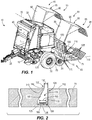
FIG. 1 is a front perspective view of an agricultural baler including a crop package reconfiguration and banding system according to an embodiment of the disclosure. -
FIG. 2 is a cross sectional view of a portion of the reconfiguration and banding system ofFIG. 1 taken along line 2-2. -
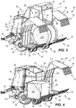
FIG. 3 is a rear perspective view of the agricultural baler ofFIG. 1 including a cylindrical-shaped crop package supported on an accumulator of the agricultural baler. -
FIG. 4 is a rear perspective view of the agricultural baler ofFIG. 1 including the cylindrical-shaped crop package reconfigured as a cuboid-shaped crop package by the reconfiguration and banding system. -
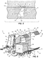
FIG. 5 is a cross sectional view of the portion of the reconfiguration and banding system ofFIG. 1 taken along line 2-2 with the cuboid-shaped crop package supported on the reconfiguration and banding system. -
FIG. 6 is a rear perspective view of the agricultural baler ofFIG. 1 including the cuboid-shaped crop package ofFIG. 4 banded by the reconfiguration and banding system. -
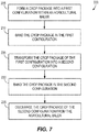
FIG. 7 illustrates a method of preparing a crop package to be discharged from the agricultural baler ofFIG. 1 . - Before any embodiments of the disclosure are explained in detail, it is to be understood that the disclosure is not limited in its application to the details of construction and the arrangement of components set forth in the following description or illustrated in the following drawings. The disclosure is capable of other embodiments and of being practiced or of being carried out in various ways. Also, it is to be understood that the phraseology and terminology used herein is for the purpose of description and should not be regarded as limiting. The use of "including," "comprising," or "having" and variations thereof herein is meant to encompass the items listed thereafter and equivalents thereof as well as additional items. Unless specified or limited otherwise, the terms "mounted," "connected," "supported," and "coupled" and variations thereof are used broadly and encompass both direct and indirect mountings, connections, supports, and couplings. Further, "connected" and "coupled" are not restricted to physical or mechanical connections or couplings. Terms of degree, such as "substantially" or "approximately" are understood by those of ordinary skill to refer to reasonable ranges outside of the given value, for example, general tolerances associated with manufacturing, assembly, and use of the described embodiments.
-
FIG. 1 illustrates anagricultural baler 10 selectively coupled to a vehicle (e.g., tractor) for the vehicle to move theagricultural baler 10 through an agricultural field. Thebaler 10 includes achassis 15,wheels 20 rotatably coupled to thechassis 15 to support thebaler 10 above the agricultural field, atongue 25 coupled to a front portion of thechassis 15 allowing thebaler 10 to be towed behind the vehicle, and agate 30 pivotably coupled to thechassis 15 about agate axis 35 between a closed position (FIG. 1 ) and an open position (FIG. 3 ). Aformation chamber 40 is defined between thechassis 15 and the gate 30-when thegate 30 is in the closed position-and is operable to form a crop package as thebaler 10 moves through the agricultural field. In the illustrated embodiment, thebaler 10 is a "round" baler that forms generally cylindrical-shaped crop packages within theformation chamber 40, however, in other embodiments, thebaler 10 can be a "square" baler that forms generally cuboid-shaped (e.g., cube, rectangular prism, etc.) crop packages within theformation chamber 40. In further embodiments, thegate 30 can be slidably coupled to thechassis 15 between the closed position and the open position. - The illustrated
baler 10 also includes anaccumulator 45 positioned downstream of theformation chamber 40 and operable to support one or more crop packages that are discharged sequentially from the formation chamber 40-when thegate 30 is in the open position. Theaccumulator 45 includes amiddle section 50 positioned between twoside sections 55 with eachsection FIG. 4 ) is slidable within themiddle section 50 to push a crop package supported on themiddle section 50 to one of the twoside sections 55. In the illustrated embodiment, eachside section 55 is substantially the same such that features of oneside section 55 are applicable to theother side section 55. As such, only one of theside sections 55 will be discussed in detail below. - The illustrated
side section 55 defines a reconfiguration and bandingsystem 65 operable to change the shape of a crop package discharged from theformation chamber 40 and to band or secure the crop package into the new shape. The illustrated reconfiguration andbanding system 65 includes afirst support frame 70 having abottom support plate 75 and a firstside support plate 80 oriented substantially perpendicular to thebottom support plate 75 such that thefirst support frame 70 is generally L-shaped in cross section (e.g., within a cross sectional plane perpendicular to thegate axis 35 or a rotational axis of the wheels 20). The reconfiguration andbanding system 65 also includes asecond support frame 85 having atop support plate 90 and a secondside support plate 95 oriented substantially perpendicular to thetop support plate 90 such that thesecond support frame 85 is also generally L-shaped in cross section similar to thefirst support frame 70. Accordingly, the first andsecond support frames first support frame 70 can include more or less than two support plates and/or thesecond support frame 85 can include more or less than two support plates with the total sum of the support plates being four. The illustrated first andsecond support frames pivot axis 100 that is oriented substantially parallel with thegate axis 35 or the rotational axis of thewheels 20. In other embodiments, thesecond support frame 85 can be slidably coupled to thefirst support frame 70. In further embodiments, the reconfiguration andbanding system 65 can define themiddle section 50 of theaccumulator 45 with the twoside sections 55 operable to simply support the crop packages above the agricultural field. In other words, thebaler 10 can include one reconfiguration andbanding system 65 rather than two. - Each support plate or
member channels 105 formed into anabutting surface 110 of eachsupport plate channel 105 is centered on a plane that is substantially perpendicular to thegate axis 35 or the rotational axis of thewheels 20. Stated another way, eachchannel 105 defines alongitudinal axis 115 oriented substantially perpendicular to thegate axis 35 or the rotational axis of the wheels 20 (only onelongitudinal axis 115 is illustrated inFIG. 1 ). The abuttingsurfaces 110 are configured to contact the crop package when the crop package is received by the reconfiguration andbanding system 65. In the illustrated embodiment, eachsupport plate channels 105, but in other embodiments, thesupport plates channels 105. In the illustrated embodiment, eachchannel 105 of thesupport plates channel 105 are applicable to theother channels 105. As such, only one of thechannels 105 with respect to thebottom support plate 75 will be discussed in detail below. In other embodiments, thechannels 105 can be differently configured. - As best shown in
FIG. 2 , thechannel 105 is defined by anopening 120 in the abutting orsupport surface 110 of thebottom support plate 75. The illustratedchannel 105 is also defined by afirst surface 125 positioned opposite asecond surface 130 and athird surface 135 extending between the first andsecond surfaces 125, 130 (e.g., thethird surface 135 is positioned opposite the opening 120). In other embodiments, thethird surface 135 can be omitted causing thechannel 105 to extend completely through thebottom support plate 75. In the illustrated embodiment, thesecond surface 130 is oriented substantially perpendicular to thesupport surface 110 of thebottom support plate 75, and thethird surface 135 is oriented substantially perpendicular to thesecond surface 130. In other embodiments, thesecond surface 130 can be obliquely oriented relative to thesupport surface 110, and/or thethird surface 135 can be obliquely oriented relative to thesecond surface 130. - The illustrated
first surface 125 includes aprotrusion 140 extending toward the second surface 130 (e.g., theprotrusion 140 tapers toward thesecond surface 130 in a direction from thethird surface 135 to the opening 120). In particular, theprotrusion 140 is formed as a fixed portion of thefirst surface 125 and configured to vary a distance between the first andsecond surfaces third surface 135 to theopening 120. The illustratedprotrusion 140 includes a tip orapex 145 that defines theopening 120 with a portion of thesecond surface 130. Theopening 120 defines awidth 150 of thechannel 105. In addition, the illustratedprotrusion 140 defines aprotrusion surface 155 extending toward thesecond surface 130 to the apex 145. Theprotrusion surface 155 is obliquely angled relative to thesupport surface 110 and thesecond surface 130. The illustratedprotrusion surface 155 is substantially linear, but in other embodiments, theprotrusion surface 155 can be non-linear (e.g., curved, etc.). - With reference back to
FIG. 1 , each reconfiguration andbanding system 65 also includes a plurality ofbander units 170 and acompartment 175 coupled to anouter surface 180 of the firstside support plate 80. In other embodiments, the plurality ofbander units 170 and/or thecompartment 175 can be coupled to any portion of thefirst support frame 70 and/or thesecond support frame 85. Thecompartment 175 is configured to hold one or more rolls of a banding element 185 (FIG. 2 ) with eachbander unit 170 coupled to thecompartment 175 to move onebanding element 185 through onechannel 105. In one embodiment, eachbander unit 170 can be at least one pinch roller that pulls abanding element 185 from thecompartment 175 and pushes thebanding element 185 through four alignedchannels 105 of the first and second support frames 70, 85. For example, eachbander unit 170 can push abanding element 185 through a portion of thechannel 105 formed in the firstside support plate 80, through an aligningchannel 105 formed within thetop support plate 90, through an aligningchannel 105 formed within the secondside support plate 95, through an aligningchannel 105 formed in thebottom support plate 75, and through the remaining portion of thechannel 105 formed in the firstside support plate 80. In other embodiments, eachbander unit 170 can push abanding element 185 in the other direction (e.g., from thebottom support plate 75, to the secondside support plate 95, to thetop support plate 90, and to the first side support plate 80). In further embodiments, eachbander unit 170 can include a puller mechanism that is driven and moveable through four aligned channels 105 (e.g., the puller mechanism is positioned between the apex 145 and thethird surface 135 to move through the channels 105) and operable to grip an end of thebanding element 185 and pull thebanding element 185 through the four alignedchannels 105 of the first and second support frames 70, 85. - With reference to
FIG. 2 , each bandingelement 185 is rectangular in cross section (in a plane perpendicular to thelongitudinal axis 115 of a corresponding channel 105) to define awidth 190 and aheight 195 with thewidth 190 being greater than theheight 195. In the illustrated embodiment, theheight 195 of each bandingelement 185 is less than thewidth 150 of thechannel 105 and thewidth 190 of each bandingelement 185 is greater than thewidth 150 of thechannel 105. In one embodiment, thewidth 190 of each bandingelement 185 is between about 0.5 inches and about 0.75 inches, and theheight 195 of each bandingelement 185 is between about 0.01 inches and about 0.2 inches. In other embodiments, each bandingelement 185 can define a different cross sectional geometry (e.g., circular, ovular, square, triangular, etc.), and/or define different cross sectional dimensions. In some embodiments, each bandingelement 185 can be made of a flexible metallic material, a flexible plastic material, etc. -
FIG. 7 illustrates amethod 200 of preparing a crop package to be discharged from thebaler 10 as shown inFIGS. 3-6 . The illustratedbaler 10 is operable to form a crop package into a first configuration (e.g., a cylindrical-shaped crop package) within the formation chamber 40 (step 205;FIG. 7 ) as thebaler 10 moves across the agricultural field. Once thebaler 10 completely forms the crop package within theformation chamber 40, thebaler 10 bands the crop package in the first configuration (step 210;FIG. 7 ) to secure the crop package in a cylindrical shape before the crop package is discharged from theformation chamber 40. For example, thebaler 10 can usesimilar banding elements 185 of the reconfiguration andbanding system 65 to band the cylindrical-shaped crop package 215 within theformation chamber 40. As discussed in more detail below, the banding operation of thebaler 10 is temporary in order to transfer the crop package from theformation chamber 40 to the reconfiguration andbanding system 65. - With reference to
FIG. 3 , thegate 30 is moved to the open position allowing the cylindrical-shaped crop package 215 to be discharged from theformation chamber 40 and onto themiddle section 50 of theaccumulator 45. The cylindrical-shaped crop package 215 can then be moved to either the twoside sections 55 by actuating the pushingmechanism 60 to move the cylindrical-shaped crop package 215 toward one of the twoside sections 55. - The
method 200 also includes a step 220 (FIG. 7 ) of transforming the cylindrical-shaped crop package 215 into a second configuration (e.g., a cuboid-shapedcrop package 225;FIG. 4 ) by the reconfiguration andbanding system 65. In particular, the cylindrical-shaped crop package 215 is captured between the first and second support frames 70, 85 as the first and second support frames 70, 85 move relative to each other about thepivot axis 100 to reconfigure and compress the cylindrical-shaped crop package 215 into the cuboid-shapedcrop package 225. As a result, sides of the cuboid-shapedcrop package 225 are in direct contact with the abuttingsurfaces 110 of thesupport plates crop package 225 between the first and second support frames 70, 85. As discussed above, the banding operation of the baler 10 (step 210) is temporary, and once the crop package is captured between the first and second support frames 70, 85, the banding elements that hold the crop package in the cylindrical shape can be removed from the crop package and collected to be reused by thebaler 10 or disposed of. - The illustrated reconfiguration and
banding system 65 is also operable to band the cuboid-shaped crop package 225 (step 230;FIG. 7 ). Thebander units 170 are actuated (e.g., the pinch rollers are rotated in a first direction) to push thebanding elements 185 around the cuboid-shapedcrop package 225. The flexibility of thebanding elements 185 allows the bandingelements 185 to easily transition between adjacent alignedchannels 105. Once thebander units 170 push thebanding elements 185 one revolution around the cuboid-shapedcrop package 225, thebander units 170 tighten thebanding elements 185 onto the cuboid-shaped crop package 225 (e.g., the pinch rollers are rotated in a second direction). As movement of thebanding elements 185 within their correspondingchannels 105 are substantially the same when the bandingelements 185 are tightened onto the cuboid-shapedcrop package 225, movement of onebanding element 185 with onechannel 105 will be discussed in detail below. -
FIG. 5 generally illustrates a sequence of movements of thebanding element 185 within thechannel 105. As thebanding element 185 is tightened onto the cuboid-shapedcrop package 225, thebanding element 185 moves toward theopening 120 and comes into contact with theprotrusion surface 155 causing thebanding element 185 to pivot and slide along theprotrusion surface 155 toward the apex 145. Once thebanding element 185 clears the apex 145, the banding element can then pivot again to an orientation substantially parallel to thesupport surface 110 and be further tightened onto the cuboid-shapedcrop package 225. - In the illustrated embodiment, as the reconfiguration and
banding system 65 compresses the cylindrical-shaped crop package 215 into the cuboid-shapedcrop package 225, material of the crop package extending over thechannels 105 will have a tendency to move into thechannels 105. The illustratedprotrusions 140 are operable to inhibit the material of the crop package from moving past theapexes 145 toward thethird surfaces 135 to avoid interference of the material with the bandingelements 185 being pushed through thechannels 105. As such, thebander units 170 can easily push thebanding elements 185 through thechannels 105 and around the cuboid-shapedcrop package 225. The illustratedprotrusions 140 are also configured to allow thebanding elements 185 to slide along theprotrusions 140 past thecorresponding apex 145 to exit thechannels 105. - Once the banding
elements 185 are tightened around the cuboid-shapedcrop package 225 and exit theircorresponding channels 105, ends of each bandingelement 185 are fastened together (e.g., by a clip, etc.) to secure the crop package in the cuboid shape. In addition, thesecond support frame 85 pivots away from the cuboid-shaped crop package 225 (FIG. 6 ) allowing the cuboid-shapedcrop package 225 to be discharged from the baler 10 (step 235;FIG. 7 ). In one embodiment, theaccumulator 45 can rotate relative to thechassis 15 of thebaler 10 allowing the cuboid-shapedcrop package 225 to move (e.g., slide, roll, etc.) off of theaccumulator 45 and onto the agricultural field. - In the illustrated embodiment, the
baler 10 includes two reconfiguration andbanding systems 65 so that a first cylindrical-shaped crop package can be formed in theformation chamber 40, discharged onto theaccumulator 45, moved to one of theside sections 55 by the pushingmechanism 60, reconfigured and compressed into a first cuboid-shaped crop package, and banded into the cuboid shape. While the first cylindrical-shaped crop package is being reconfigured and compressed into the first cuboid-shaped crop package and banded into the cuboid shape, thebaler 10 can also form a second cylindrical-shaped crop package in theformation chamber 40 to be discharged onto theaccumulator 45, moved to theother side section 55 by the pushingmechanism 60, reconfigured and compressed into a second cuboid-shaped crop package, and banded into the cuboid shape. As a result, theaccumulator 45 can support two cuboid-shaped crop packages at a time before discharging the cuboid-shaped crop packages from thebaler 10. - In the embodiment with one reconfiguration and
banding system 65 located in themiddle section 50 of theaccumulator 45, thebaler 10 is operable to form a first cylindrical-shaped crop package in theformation chamber 40 to be discharged to the reconfiguration andbanding system 65 for the reconfiguration andbanding system 65 to reconfigure and compress the first cylindrical-shaped crop package into a first cuboid-shaped crop package and to band the first cuboid-shaped crop package to then be moved to one of the twoside sections 55 by the pushingmechanism 60. A similar process occurs when thebaler 10 produces a second cylindrical-shaped crop package in theformation chamber 40 to be discharged to the reconfiguration andbanding system 65 to be reconfigured and banded as a second cuboid-shaped crop package before being moved to theother side section 55. - In further embodiments, the
baler 10 can form a first cuboid-shaped crop package within theformation chamber 40 and the reconfiguration andbanding system 65 can compress the first cuboid-shaped crop package into a smaller, more dense second cuboid-shaped crop package. - Although the disclosure has been described in detail with reference to certain preferred embodiments, variations and modifications exist within the scope and spirit of one or more independent aspects of the disclosure as described. Various features and advantages of the disclosure are set forth in the following claims.
Claims (14)
- An agricultural baler comprising:a frame (15);a gate (30) moveably coupled to the frame (15) between an open position anda closed position;a formation chamber (40) positioned between the frame (15) and the gate (30), the formation chamber (40) configured to form a crop package; anda banding system (65) including a support member (75, 80, 90, 95) including a support surface configured to support the crop package, the support member (75, 80, 90, 95) including a channel (105) defined by an opening (120) in the support surface, the channel (105) further defined by a first surface (125) opposite a second surface (130) and a third surface (135) extending between the first and second surfaces (125, 130), the first surface (125) including a protrusion (140) extending toward the second surface (130), the protrusion (140) including an apex (145) that partially forms the opening (120), anda bander unit (170) configured to move a banding element (185) within the channel (105) to band the crop package.
- The agricultural baler of claim 1, wherein the protrusion (140) is at least partially defined by a protrusion surface (155) angled relative to the second surface (130).
- The agricultural baler of claim 2, wherein the protrusion (140) is configured to block a portion of material from the crop package moving past the apex (145) of the protrusion (140) toward the third surface (135), and wherein the protrusion (140) is configured to allow the banding element (185) to slide along the protrusion surface (155) past the apex (145) of the protrusion (140) to exit the channel (105).
- The agricultural baler according to at least one of the preceding claims, wherein the protrusion (140) is a fixed protrusion formed as a portion of the first surface (125), and wherein the protrusion (140) is at least partially defined by a linear surface angled relative to the second surface (130).
- The agricultural baler according to at least one of the preceding claims, wherein the channel (105) defines a longitudinal axis (115), and wherein the banding element (185) is configured to extend within the channel (105) along the longitudinal axis (115), and wherein the banding element (185) defines a width greater than a height, and wherein the width and the height are oriented perpendicular to the longitudinal axis (115), and wherein a width of the channel (105) defined by the opening (120) is greater than the height of the banding element (185) and less than the width of the banding element (185).
- The agricultural baler according to at least one of the preceding claims, wherein the support member (75, 80, 90, 95) includes a plurality of spaced channels (105) with each channel (105) of the plurality of channels (105) defined by an opening (120) in the support surface, and wherein each channel (105) of the plurality of channels (105) is further defined by a first surface (125) opposite a second surface (130) and a third surface (135) extending between the first and second surfaces (125, 130), and wherein the first surface (125) of each channel (105) of the plurality of channels (105) at least partially defines a protrusion (140) extending toward the second surface (130) of the corresponding channel (105) such that an apex (145) of each protrusion (140) partially forms the opening (120) of the corresponding channel (105), and wherein the banding system (65) includes a plurality of bander units (170) each associated with one channel (105) of the plurality of channels (105).
- The agricultural baler according to at least one of the preceding claims, wherein the formation chamber (40) is configured to form the crop package into a first configuration, and wherein the banding system (65) is configured to receive the crop package in the first configuration and band the crop package into a second configuration.
- The agricultural baler according to at least one of the preceding claims, wherein the first configuration is a cylindrical-shaped crop package, and wherein the second configuration is a cuboid-shaped crop package.
- A banding system for an agricultural baler, the banding system (65) configured to move a banding element (185) around a crop package to band the crop package, the banding system (65) comprising:a support member (75, 80, 90, 95) including a support surface configured to support the crop package, the support member (75, 80, 90, 95) including a channel (105) defined by an opening (120) in the support surface, the channel (105) further defined by a first surface (125) opposite a second surface (130) and a third surface (135) extending between the first and second surfaces (125, 130), the first surface (125) at least partially defining an angled surface tapering toward the second surface (130) such that an apex of the angled surface partially forms the opening (120); anda bander unit (170) configured to move a banding element (185) within the channel (105) to band the crop package.
- The banding system of claim 9, wherein the angled surface is a linear angled surface.
- The banding system of claim 9 or 10, wherein the channel (105) defines a longitudinal axis (115), and wherein the banding element (185) is configured to extend within the channel (105) along the longitudinal axis (115), and wherein the banding element (185) defines a width greater than a height, and wherein the width and the height are oriented perpendicular to the longitudinal axis (115), and wherein a width of the channel (105) defined by the opening (120) is greater than the height of the banding element (185) and less than the width of the banding element (185).
- The banding system according to at least one of the claims 9 to 11, wherein at least a portion of the banding element (185) is configured to slide along the angled surface before exiting the channel (105).
- The banding system according to at least one of the claims 9 to 12, wherein the support member (75, 80, 90, 95) includes a plurality of spaced channels (105) with each channel (105) of the plurality of channels (105) defined by an opening (120) in the support surface, and wherein each channel (105) of the plurality of channels (105) is further defined by a first surface (125) opposite a second surface (130) and a third surface (135) extending between the first and second surfaces (125, 130), and wherein the first surface (125) of each channel (105) of the plurality of channels (105) at least partially defines an angled surface tapering toward the second surface (130) of the corresponding channel (105) such that a portion of the angled surface partially forms the opening (120) of the corresponding channel (105), and wherein the banding system (65) includes a plurality of bander units (170) each associated with one channel (105) of the plurality of channels (105).
- The banding system according to at least one of the claims 9 to 12, wherein the support member (75, 80, 90, 95) is configured to support a cuboid-shaped crop package, and wherein the bander unit (170) is configured to band the cuboid-shaped crop package.
Applications Claiming Priority (1)
| Application Number | Priority Date | Filing Date | Title |
|---|---|---|---|
| US16/031,506 US10820526B2 (en) | 2018-07-10 | 2018-07-10 | Agricultural baler including crop package banding system and method |
Publications (2)
| Publication Number | Publication Date |
|---|---|
| EP3593628A1 true EP3593628A1 (en) | 2020-01-15 |
| EP3593628B1 EP3593628B1 (en) | 2022-08-31 |
Family
ID=67145729
Family Applications (1)
| Application Number | Title | Priority Date | Filing Date |
|---|---|---|---|
| EP19184175.8A Active EP3593628B1 (en) | 2018-07-10 | 2019-07-03 | Agricultural baler including crop package banding system |
Country Status (2)
| Country | Link |
|---|---|
| US (1) | US10820526B2 (en) |
| EP (1) | EP3593628B1 (en) |
Cited By (1)
| Publication number | Priority date | Publication date | Assignee | Title |
|---|---|---|---|---|
| US11547055B2 (en) | 2019-01-09 | 2023-01-10 | Great Plains Manufacturing, Inc. | Rotor for a high capacity baler |
Citations (4)
| Publication number | Priority date | Publication date | Assignee | Title |
|---|---|---|---|---|
| DE10131165A1 (en) * | 2001-06-29 | 2003-02-06 | Hermann Schwelling | Method for strapping a pressed bale of material in the shaft of a bale press, involves use of a strapping material which is cut into a length determined before the pressing operation |
| EP2628591A2 (en) * | 2012-02-17 | 2013-08-21 | SIB Strautmann Ingenieurbüro GmbH | Press for manufacturing pressed bales, binding device and re-pressing device |
| WO2015153300A1 (en) * | 2014-03-31 | 2015-10-08 | Cnh Industrial America Llc | Strapping system for agricultural implement |
| EP3461321A1 (en) * | 2017-10-02 | 2019-04-03 | Deere & Company | System and method for recompressing round bales into square bales |
Family Cites Families (18)
| Publication number | Priority date | Publication date | Assignee | Title |
|---|---|---|---|---|
| US3195445A (en) | 1963-01-07 | 1965-07-20 | Sidney S Meisler | Bale press |
| US4177723A (en) | 1978-02-08 | 1979-12-11 | Iowa State University Research Foundation, Inc. | Compactor device for large round bales |
| US4697510A (en) * | 1986-12-22 | 1987-10-06 | Cranston Machinery Co., Inc. | Contamination deflector system for bale binding machines |
| NL1002947C2 (en) | 1996-04-25 | 1997-10-28 | Maasland Nv | Baler. |
| US6425235B1 (en) * | 1997-09-02 | 2002-07-30 | Phillip G. Spaniol | Agricultural bale accumulator having a load bed extension module |
| DE10044166A1 (en) | 2000-09-07 | 2002-03-21 | Deere & Co | Combination of a press, a winding device and a chassis that accommodates them |
| US6499525B1 (en) * | 2001-06-27 | 2002-12-31 | Chien-Fa Lai | Tape support for an automatic wrapper |
| ATE336430T1 (en) * | 2002-06-28 | 2006-09-15 | Ferag Ag | STRAPING DEVICE |
| DE10240091A1 (en) | 2002-08-28 | 2004-03-11 | Deere & Company, Moline | wrapping machine |
| US6769353B1 (en) | 2003-02-28 | 2004-08-03 | New Holland North America, Inc. | Four twine tube round baler twine system |
| US7127985B2 (en) | 2003-09-11 | 2006-10-31 | Standlee Michael G | Method and apparatus for creating consumer friendly hay bales |
| US7237478B1 (en) * | 2006-08-02 | 2007-07-03 | Illinois Tool Works Inc. | Asymmetrical strap chute and release system |
| EP2149293B1 (en) | 2008-07-31 | 2011-06-29 | Deere & Company | Baler and wrapper combination |
| US8833247B2 (en) | 2010-12-27 | 2014-09-16 | Agco Corporation | Giant round baler compressor |
| WO2013109831A1 (en) * | 2012-01-18 | 2013-07-25 | Stein Del Bradley | System and method for applying strapping to bales of material |
| WO2014144470A1 (en) | 2013-03-15 | 2014-09-18 | Cnh Industrial America Llc | System and method for baling agricultural crop material |
| US9622420B2 (en) * | 2014-07-17 | 2017-04-18 | Deere & Company | Agricultural baler platform |
| US10820523B2 (en) | 2017-10-02 | 2020-11-03 | Deere & Company | System and method for recompressing round bales into square bales |
-
2018
- 2018-07-10 US US16/031,506 patent/US10820526B2/en active Active
-
2019
- 2019-07-03 EP EP19184175.8A patent/EP3593628B1/en active Active
Patent Citations (4)
| Publication number | Priority date | Publication date | Assignee | Title |
|---|---|---|---|---|
| DE10131165A1 (en) * | 2001-06-29 | 2003-02-06 | Hermann Schwelling | Method for strapping a pressed bale of material in the shaft of a bale press, involves use of a strapping material which is cut into a length determined before the pressing operation |
| EP2628591A2 (en) * | 2012-02-17 | 2013-08-21 | SIB Strautmann Ingenieurbüro GmbH | Press for manufacturing pressed bales, binding device and re-pressing device |
| WO2015153300A1 (en) * | 2014-03-31 | 2015-10-08 | Cnh Industrial America Llc | Strapping system for agricultural implement |
| EP3461321A1 (en) * | 2017-10-02 | 2019-04-03 | Deere & Company | System and method for recompressing round bales into square bales |
Cited By (5)
| Publication number | Priority date | Publication date | Assignee | Title |
|---|---|---|---|---|
| US11547055B2 (en) | 2019-01-09 | 2023-01-10 | Great Plains Manufacturing, Inc. | Rotor for a high capacity baler |
| US11559002B2 (en) * | 2019-01-09 | 2023-01-24 | Great Plains Manufacturing, Inc. | Singulating system for high capacity baler |
| US11576307B2 (en) | 2019-01-09 | 2023-02-14 | Great Plains Manufacturing, Inc. | Bundling system for high capacity baler |
| US11576306B2 (en) | 2019-01-09 | 2023-02-14 | Great Plains Manufacturing, Inc. | Display for high capacity baler |
| US11825773B2 (en) | 2019-01-09 | 2023-11-28 | Great Plains Manufacturing, Inc. | High capacity baler |
Also Published As
| Publication number | Publication date |
|---|---|
| US10820526B2 (en) | 2020-11-03 |
| US20200015425A1 (en) | 2020-01-16 |
| EP3593628B1 (en) | 2022-08-31 |
| BR102019009934A2 (en) | 2020-02-04 |
Similar Documents
| Publication | Publication Date | Title |
|---|---|---|
| US6170245B1 (en) | Round bale forming roll | |
| DE4100276C2 (en) | Strapping machine | |
| EP0965263B1 (en) | Round bale wrapping apparatus | |
| US20120204734A1 (en) | Baling device to form bales of crop material | |
| EP3593629B1 (en) | Agricultural baler including crop package banding system and method | |
| EP3593628B1 (en) | Agricultural baler including crop package banding system | |
| CN105377017B (en) | Baling press | |
| US20080098692A1 (en) | Wrapping Device | |
| US7784400B2 (en) | Duckbill cam geometry for reduced actuation forces | |
| US20030226334A1 (en) | Pivoting side twine box for round balers | |
| US4240245A (en) | Device for baling cut crops | |
| US5191833A (en) | Roll stripping apparatus for round baler | |
| CN115568341A (en) | Shaft assemblies as well as round bales or modules to build machines and systems | |
| US9038532B2 (en) | Movable friction blocks for a rectangular baler | |
| US10806090B2 (en) | Agricultural baler system including crop package reconfiguration and banding mechanism and method | |
| WO2006135869B1 (en) | High-compression baler | |
| US7386967B2 (en) | Round baler | |
| US7140294B1 (en) | Round baler bale ejecting arrangement | |
| US10820524B2 (en) | Wrapping device and round baler | |
| EP3964047B1 (en) | Crop stop for bale roll | |
| BR102019009936B1 (en) | AGRICULTURAL BALER AND BANDING SYSTEM FOR AN AGRICULTURAL BALER | |
| EP4470361A1 (en) | Gate latch pocket deflector | |
| CN211196853U (en) | Hold down subassembly | |
| JPH0244956Y2 (en) | ||
| DE60313265T2 (en) | Machine and method for bundling plant stems |
Legal Events
| Date | Code | Title | Description |
|---|---|---|---|
| PUAI | Public reference made under article 153(3) epc to a published international application that has entered the european phase |
Free format text: ORIGINAL CODE: 0009012 |
|
| STAA | Information on the status of an ep patent application or granted ep patent |
Free format text: STATUS: THE APPLICATION HAS BEEN PUBLISHED |
|
| AK | Designated contracting states |
Kind code of ref document: A1 Designated state(s): AL AT BE BG CH CY CZ DE DK EE ES FI FR GB GR HR HU IE IS IT LI LT LU LV MC MK MT NL NO PL PT RO RS SE SI SK SM TR |
|
| AX | Request for extension of the european patent |
Extension state: BA ME |
|
| STAA | Information on the status of an ep patent application or granted ep patent |
Free format text: STATUS: REQUEST FOR EXAMINATION WAS MADE |
|
| 17P | Request for examination filed |
Effective date: 20200715 |
|
| RBV | Designated contracting states (corrected) |
Designated state(s): AL AT BE BG CH CY CZ DE DK EE ES FI FR GB GR HR HU IE IS IT LI LT LU LV MC MK MT NL NO PL PT RO RS SE SI SK SM TR |
|
| GRAP | Despatch of communication of intention to grant a patent |
Free format text: ORIGINAL CODE: EPIDOSNIGR1 |
|
| STAA | Information on the status of an ep patent application or granted ep patent |
Free format text: STATUS: GRANT OF PATENT IS INTENDED |
|
| INTG | Intention to grant announced |
Effective date: 20220510 |
|
| GRAS | Grant fee paid |
Free format text: ORIGINAL CODE: EPIDOSNIGR3 |
|
| GRAA | (expected) grant |
Free format text: ORIGINAL CODE: 0009210 |
|
| STAA | Information on the status of an ep patent application or granted ep patent |
Free format text: STATUS: THE PATENT HAS BEEN GRANTED |
|
| AK | Designated contracting states |
Kind code of ref document: B1 Designated state(s): AL AT BE BG CH CY CZ DE DK EE ES FI FR GB GR HR HU IE IS IT LI LT LU LV MC MK MT NL NO PL PT RO RS SE SI SK SM TR |
|
| REG | Reference to a national code |
Ref country code: CH Ref legal event code: EP Ref country code: GB Ref legal event code: FG4D |
|
| REG | Reference to a national code |
Ref country code: AT Ref legal event code: REF Ref document number: 1514620 Country of ref document: AT Kind code of ref document: T Effective date: 20220915 |
|
| REG | Reference to a national code |
Ref country code: DE Ref legal event code: R096 Ref document number: 602019018860 Country of ref document: DE |
|
| REG | Reference to a national code |
Ref country code: IE Ref legal event code: FG4D |
|
| REG | Reference to a national code |
Ref country code: LT Ref legal event code: MG9D |
|
| REG | Reference to a national code |
Ref country code: NL Ref legal event code: MP Effective date: 20220831 |
|
| PG25 | Lapsed in a contracting state [announced via postgrant information from national office to epo] |
Ref country code: SE Free format text: LAPSE BECAUSE OF FAILURE TO SUBMIT A TRANSLATION OF THE DESCRIPTION OR TO PAY THE FEE WITHIN THE PRESCRIBED TIME-LIMIT Effective date: 20220831 Ref country code: RS Free format text: LAPSE BECAUSE OF FAILURE TO SUBMIT A TRANSLATION OF THE DESCRIPTION OR TO PAY THE FEE WITHIN THE PRESCRIBED TIME-LIMIT Effective date: 20220831 Ref country code: NO Free format text: LAPSE BECAUSE OF FAILURE TO SUBMIT A TRANSLATION OF THE DESCRIPTION OR TO PAY THE FEE WITHIN THE PRESCRIBED TIME-LIMIT Effective date: 20221130 Ref country code: LV Free format text: LAPSE BECAUSE OF FAILURE TO SUBMIT A TRANSLATION OF THE DESCRIPTION OR TO PAY THE FEE WITHIN THE PRESCRIBED TIME-LIMIT Effective date: 20220831 Ref country code: LT Free format text: LAPSE BECAUSE OF FAILURE TO SUBMIT A TRANSLATION OF THE DESCRIPTION OR TO PAY THE FEE WITHIN THE PRESCRIBED TIME-LIMIT Effective date: 20220831 Ref country code: FI Free format text: LAPSE BECAUSE OF FAILURE TO SUBMIT A TRANSLATION OF THE DESCRIPTION OR TO PAY THE FEE WITHIN THE PRESCRIBED TIME-LIMIT Effective date: 20220831 |
|
| REG | Reference to a national code |
Ref country code: AT Ref legal event code: MK05 Ref document number: 1514620 Country of ref document: AT Kind code of ref document: T Effective date: 20220831 |
|
| PG25 | Lapsed in a contracting state [announced via postgrant information from national office to epo] |
Ref country code: PL Free format text: LAPSE BECAUSE OF FAILURE TO SUBMIT A TRANSLATION OF THE DESCRIPTION OR TO PAY THE FEE WITHIN THE PRESCRIBED TIME-LIMIT Effective date: 20220831 Ref country code: IS Free format text: LAPSE BECAUSE OF FAILURE TO SUBMIT A TRANSLATION OF THE DESCRIPTION OR TO PAY THE FEE WITHIN THE PRESCRIBED TIME-LIMIT Effective date: 20221231 Ref country code: HR Free format text: LAPSE BECAUSE OF FAILURE TO SUBMIT A TRANSLATION OF THE DESCRIPTION OR TO PAY THE FEE WITHIN THE PRESCRIBED TIME-LIMIT Effective date: 20220831 Ref country code: GR Free format text: LAPSE BECAUSE OF FAILURE TO SUBMIT A TRANSLATION OF THE DESCRIPTION OR TO PAY THE FEE WITHIN THE PRESCRIBED TIME-LIMIT Effective date: 20221201 |
|
| PG25 | Lapsed in a contracting state [announced via postgrant information from national office to epo] |
Ref country code: SM Free format text: LAPSE BECAUSE OF FAILURE TO SUBMIT A TRANSLATION OF THE DESCRIPTION OR TO PAY THE FEE WITHIN THE PRESCRIBED TIME-LIMIT Effective date: 20220831 Ref country code: RO Free format text: LAPSE BECAUSE OF FAILURE TO SUBMIT A TRANSLATION OF THE DESCRIPTION OR TO PAY THE FEE WITHIN THE PRESCRIBED TIME-LIMIT Effective date: 20220831 Ref country code: PT Free format text: LAPSE BECAUSE OF FAILURE TO SUBMIT A TRANSLATION OF THE DESCRIPTION OR TO PAY THE FEE WITHIN THE PRESCRIBED TIME-LIMIT Effective date: 20230102 Ref country code: ES Free format text: LAPSE BECAUSE OF FAILURE TO SUBMIT A TRANSLATION OF THE DESCRIPTION OR TO PAY THE FEE WITHIN THE PRESCRIBED TIME-LIMIT Effective date: 20220831 Ref country code: DK Free format text: LAPSE BECAUSE OF FAILURE TO SUBMIT A TRANSLATION OF THE DESCRIPTION OR TO PAY THE FEE WITHIN THE PRESCRIBED TIME-LIMIT Effective date: 20220831 Ref country code: CZ Free format text: LAPSE BECAUSE OF FAILURE TO SUBMIT A TRANSLATION OF THE DESCRIPTION OR TO PAY THE FEE WITHIN THE PRESCRIBED TIME-LIMIT Effective date: 20220831 Ref country code: AT Free format text: LAPSE BECAUSE OF FAILURE TO SUBMIT A TRANSLATION OF THE DESCRIPTION OR TO PAY THE FEE WITHIN THE PRESCRIBED TIME-LIMIT Effective date: 20220831 |
|
| PG25 | Lapsed in a contracting state [announced via postgrant information from national office to epo] |
Ref country code: SK Free format text: LAPSE BECAUSE OF FAILURE TO SUBMIT A TRANSLATION OF THE DESCRIPTION OR TO PAY THE FEE WITHIN THE PRESCRIBED TIME-LIMIT Effective date: 20220831 Ref country code: EE Free format text: LAPSE BECAUSE OF FAILURE TO SUBMIT A TRANSLATION OF THE DESCRIPTION OR TO PAY THE FEE WITHIN THE PRESCRIBED TIME-LIMIT Effective date: 20220831 |
|
| REG | Reference to a national code |
Ref country code: DE Ref legal event code: R097 Ref document number: 602019018860 Country of ref document: DE |
|
| PG25 | Lapsed in a contracting state [announced via postgrant information from national office to epo] |
Ref country code: NL Free format text: LAPSE BECAUSE OF FAILURE TO SUBMIT A TRANSLATION OF THE DESCRIPTION OR TO PAY THE FEE WITHIN THE PRESCRIBED TIME-LIMIT Effective date: 20220831 Ref country code: AL Free format text: LAPSE BECAUSE OF FAILURE TO SUBMIT A TRANSLATION OF THE DESCRIPTION OR TO PAY THE FEE WITHIN THE PRESCRIBED TIME-LIMIT Effective date: 20220831 |
|
| PLBE | No opposition filed within time limit |
Free format text: ORIGINAL CODE: 0009261 |
|
| STAA | Information on the status of an ep patent application or granted ep patent |
Free format text: STATUS: NO OPPOSITION FILED WITHIN TIME LIMIT |
|
| 26N | No opposition filed |
Effective date: 20230601 |
|
| PG25 | Lapsed in a contracting state [announced via postgrant information from national office to epo] |
Ref country code: SI Free format text: LAPSE BECAUSE OF FAILURE TO SUBMIT A TRANSLATION OF THE DESCRIPTION OR TO PAY THE FEE WITHIN THE PRESCRIBED TIME-LIMIT Effective date: 20220831 |
|
| PG25 | Lapsed in a contracting state [announced via postgrant information from national office to epo] |
Ref country code: MC Free format text: LAPSE BECAUSE OF FAILURE TO SUBMIT A TRANSLATION OF THE DESCRIPTION OR TO PAY THE FEE WITHIN THE PRESCRIBED TIME-LIMIT Effective date: 20220831 |
|
| PG25 | Lapsed in a contracting state [announced via postgrant information from national office to epo] |
Ref country code: MC Free format text: LAPSE BECAUSE OF FAILURE TO SUBMIT A TRANSLATION OF THE DESCRIPTION OR TO PAY THE FEE WITHIN THE PRESCRIBED TIME-LIMIT Effective date: 20220831 |
|
| REG | Reference to a national code |
Ref country code: CH Ref legal event code: PL |
|
| REG | Reference to a national code |
Ref country code: BE Ref legal event code: MM Effective date: 20230731 |
|
| PG25 | Lapsed in a contracting state [announced via postgrant information from national office to epo] |
Ref country code: LU Free format text: LAPSE BECAUSE OF NON-PAYMENT OF DUE FEES Effective date: 20230703 |
|
| GBPC | Gb: european patent ceased through non-payment of renewal fee |
Effective date: 20230703 |
|
| PG25 | Lapsed in a contracting state [announced via postgrant information from national office to epo] |
Ref country code: LU Free format text: LAPSE BECAUSE OF NON-PAYMENT OF DUE FEES Effective date: 20230703 |
|
| REG | Reference to a national code |
Ref country code: IE Ref legal event code: MM4A |
|
| PG25 | Lapsed in a contracting state [announced via postgrant information from national office to epo] |
Ref country code: CH Free format text: LAPSE BECAUSE OF NON-PAYMENT OF DUE FEES Effective date: 20230731 Ref country code: GB Free format text: LAPSE BECAUSE OF NON-PAYMENT OF DUE FEES Effective date: 20230703 |
|
| PG25 | Lapsed in a contracting state [announced via postgrant information from national office to epo] |
Ref country code: IT Free format text: LAPSE BECAUSE OF FAILURE TO SUBMIT A TRANSLATION OF THE DESCRIPTION OR TO PAY THE FEE WITHIN THE PRESCRIBED TIME-LIMIT Effective date: 20220831 Ref country code: BE Free format text: LAPSE BECAUSE OF NON-PAYMENT OF DUE FEES Effective date: 20230731 |
|
| PG25 | Lapsed in a contracting state [announced via postgrant information from national office to epo] |
Ref country code: IE Free format text: LAPSE BECAUSE OF NON-PAYMENT OF DUE FEES Effective date: 20230703 |
|
| PG25 | Lapsed in a contracting state [announced via postgrant information from national office to epo] |
Ref country code: IE Free format text: LAPSE BECAUSE OF NON-PAYMENT OF DUE FEES Effective date: 20230703 |
|
| PG25 | Lapsed in a contracting state [announced via postgrant information from national office to epo] |
Ref country code: BG Free format text: LAPSE BECAUSE OF FAILURE TO SUBMIT A TRANSLATION OF THE DESCRIPTION OR TO PAY THE FEE WITHIN THE PRESCRIBED TIME-LIMIT Effective date: 20220831 |
|
| PG25 | Lapsed in a contracting state [announced via postgrant information from national office to epo] |
Ref country code: BG Free format text: LAPSE BECAUSE OF FAILURE TO SUBMIT A TRANSLATION OF THE DESCRIPTION OR TO PAY THE FEE WITHIN THE PRESCRIBED TIME-LIMIT Effective date: 20220831 |
|
| PG25 | Lapsed in a contracting state [announced via postgrant information from national office to epo] |
Ref country code: CY Free format text: LAPSE BECAUSE OF FAILURE TO SUBMIT A TRANSLATION OF THE DESCRIPTION OR TO PAY THE FEE WITHIN THE PRESCRIBED TIME-LIMIT; INVALID AB INITIO Effective date: 20190703 |
|
| PG25 | Lapsed in a contracting state [announced via postgrant information from national office to epo] |
Ref country code: HU Free format text: LAPSE BECAUSE OF FAILURE TO SUBMIT A TRANSLATION OF THE DESCRIPTION OR TO PAY THE FEE WITHIN THE PRESCRIBED TIME-LIMIT; INVALID AB INITIO Effective date: 20190703 |
|
| PGFP | Annual fee paid to national office [announced via postgrant information from national office to epo] |
Ref country code: DE Payment date: 20250620 Year of fee payment: 7 |
|
| PGFP | Annual fee paid to national office [announced via postgrant information from national office to epo] |
Ref country code: FR Payment date: 20250725 Year of fee payment: 7 |
|
| PG25 | Lapsed in a contracting state [announced via postgrant information from national office to epo] |
Ref country code: TR Free format text: LAPSE BECAUSE OF FAILURE TO SUBMIT A TRANSLATION OF THE DESCRIPTION OR TO PAY THE FEE WITHIN THE PRESCRIBED TIME-LIMIT Effective date: 20220831 |