EP3593095B1 - Apparatus for dispensing a flowable product - Google Patents
Apparatus for dispensing a flowable product Download PDFInfo
- Publication number
- EP3593095B1 EP3593095B1 EP18714013.2A EP18714013A EP3593095B1 EP 3593095 B1 EP3593095 B1 EP 3593095B1 EP 18714013 A EP18714013 A EP 18714013A EP 3593095 B1 EP3593095 B1 EP 3593095B1
- Authority
- EP
- European Patent Office
- Prior art keywords
- piston
- chamber
- flowable product
- control unit
- collapsible container
- Prior art date
- Legal status (The legal status is an assumption and is not a legal conclusion. Google has not performed a legal analysis and makes no representation as to the accuracy of the status listed.)
- Active
Links
Images






Classifications
-
- G—PHYSICS
- G01—MEASURING; TESTING
- G01F—MEASURING VOLUME, VOLUME FLOW, MASS FLOW OR LIQUID LEVEL; METERING BY VOLUME
- G01F11/00—Apparatus requiring external operation adapted at each repeated and identical operation to measure and separate a predetermined volume of fluid or fluent solid material from a supply or container, without regard to weight, and to deliver it
- G01F11/02—Apparatus requiring external operation adapted at each repeated and identical operation to measure and separate a predetermined volume of fluid or fluent solid material from a supply or container, without regard to weight, and to deliver it with measuring chambers which expand or contract during measurement
- G01F11/021—Apparatus requiring external operation adapted at each repeated and identical operation to measure and separate a predetermined volume of fluid or fluent solid material from a supply or container, without regard to weight, and to deliver it with measuring chambers which expand or contract during measurement of the piston type
-
- B—PERFORMING OPERATIONS; TRANSPORTING
- B65—CONVEYING; PACKING; STORING; HANDLING THIN OR FILAMENTARY MATERIAL
- B65D—CONTAINERS FOR STORAGE OR TRANSPORT OF ARTICLES OR MATERIALS, e.g. BAGS, BARRELS, BOTTLES, BOXES, CANS, CARTONS, CRATES, DRUMS, JARS, TANKS, HOPPERS, FORWARDING CONTAINERS; ACCESSORIES, CLOSURES, OR FITTINGS THEREFOR; PACKAGING ELEMENTS; PACKAGES
- B65D83/00—Containers or packages with special means for dispensing contents
- B65D83/76—Containers or packages with special means for dispensing contents for dispensing fluent contents by means of a piston
-
- B—PERFORMING OPERATIONS; TRANSPORTING
- B65—CONVEYING; PACKING; STORING; HANDLING THIN OR FILAMENTARY MATERIAL
- B65D—CONTAINERS FOR STORAGE OR TRANSPORT OF ARTICLES OR MATERIALS, e.g. BAGS, BARRELS, BOTTLES, BOXES, CANS, CARTONS, CRATES, DRUMS, JARS, TANKS, HOPPERS, FORWARDING CONTAINERS; ACCESSORIES, CLOSURES, OR FITTINGS THEREFOR; PACKAGING ELEMENTS; PACKAGES
- B65D83/00—Containers or packages with special means for dispensing contents
- B65D83/771—Containers or packages with special means for dispensing contents for dispensing fluent contents by means of a flexible bag or a deformable membrane or diaphragm
-
- G—PHYSICS
- G01—MEASURING; TESTING
- G01F—MEASURING VOLUME, VOLUME FLOW, MASS FLOW OR LIQUID LEVEL; METERING BY VOLUME
- G01F11/00—Apparatus requiring external operation adapted at each repeated and identical operation to measure and separate a predetermined volume of fluid or fluent solid material from a supply or container, without regard to weight, and to deliver it
- G01F11/02—Apparatus requiring external operation adapted at each repeated and identical operation to measure and separate a predetermined volume of fluid or fluent solid material from a supply or container, without regard to weight, and to deliver it with measuring chambers which expand or contract during measurement
- G01F11/021—Apparatus requiring external operation adapted at each repeated and identical operation to measure and separate a predetermined volume of fluid or fluent solid material from a supply or container, without regard to weight, and to deliver it with measuring chambers which expand or contract during measurement of the piston type
- G01F11/029—Apparatus requiring external operation adapted at each repeated and identical operation to measure and separate a predetermined volume of fluid or fluent solid material from a supply or container, without regard to weight, and to deliver it with measuring chambers which expand or contract during measurement of the piston type provided with electric controlling means
-
- B—PERFORMING OPERATIONS; TRANSPORTING
- B65—CONVEYING; PACKING; STORING; HANDLING THIN OR FILAMENTARY MATERIAL
- B65D—CONTAINERS FOR STORAGE OR TRANSPORT OF ARTICLES OR MATERIALS, e.g. BAGS, BARRELS, BOTTLES, BOXES, CANS, CARTONS, CRATES, DRUMS, JARS, TANKS, HOPPERS, FORWARDING CONTAINERS; ACCESSORIES, CLOSURES, OR FITTINGS THEREFOR; PACKAGING ELEMENTS; PACKAGES
- B65D2231/00—Means for facilitating the complete expelling of the contents
- B65D2231/001—Means for facilitating the complete expelling of the contents the container being a bag
-
- G—PHYSICS
- G01—MEASURING; TESTING
- G01F—MEASURING VOLUME, VOLUME FLOW, MASS FLOW OR LIQUID LEVEL; METERING BY VOLUME
- G01F11/00—Apparatus requiring external operation adapted at each repeated and identical operation to measure and separate a predetermined volume of fluid or fluent solid material from a supply or container, without regard to weight, and to deliver it
- G01F11/10—Apparatus requiring external operation adapted at each repeated and identical operation to measure and separate a predetermined volume of fluid or fluent solid material from a supply or container, without regard to weight, and to deliver it with measuring chambers moved during operation
- G01F11/12—Apparatus requiring external operation adapted at each repeated and identical operation to measure and separate a predetermined volume of fluid or fluent solid material from a supply or container, without regard to weight, and to deliver it with measuring chambers moved during operation of the valve type, i.e. the separating being effected by fluid-tight or powder-tight movements
- G01F11/125—Apparatus requiring external operation adapted at each repeated and identical operation to measure and separate a predetermined volume of fluid or fluent solid material from a supply or container, without regard to weight, and to deliver it with measuring chambers moved during operation of the valve type, i.e. the separating being effected by fluid-tight or powder-tight movements of the peristaltic pump type
Definitions
- the present disclosure relates generally to an apparatus for dispensing a flowable product. More particularly, the present disclosure relates to an apparatus for dispensing a flowable product from an air-tight cavity of a collapsible container connected to the apparatus.
- Automated dispensing apparatus are used in a wide variety of applications to enable accurate quantities of flowable products to dispensed and mixed together.
- One such application is in the dispensing of hair colourings and an example of an automatic dispensing apparatus for hair colourings is described in US 2012/0048880 A1 .
- the preamble of claim 1 is derivable from WO 98/38480 A1 and US 2015/0289704 A1 , which describe prior art apparatuses for dispensing a flowable product.
- an apparatus for dispensing a flowable product from a collapsible container comprising an air-tight cavity and an opening, the apparatus comprising:
- the piston may be movable between the first position defining the maximum chamber volume and a second position defining a minimum chamber volume.
- Flowable product is delivered from the air-tight cavity of a connected collapsible container into the chamber and is stored in the chamber.
- the chamber contains a known predetermined volume of flowable product that is available for dispensing.
- the piston is in the second position defining the minimum chamber volume, the chamber may be substantially empty and substantially devoid of all flowable product.
- the apparatus may comprise a control unit.
- the control unit may be arranged to monitor a characteristic associated with the movement of the piston and may be arranged to recognise when the monitored characteristic indicates that flowable product is not available for delivery to the chamber from the air-tight cavity of a connected collapsible container.
- the control unit may be arranged to generate an alert upon recognising that the monitored characteristic indicates that flowable product is not available for delivery to the chamber from the air-tight cavity of a connected collapsible container.
- the alert could, for example, be a visual and/or an audible alert.
- Movement of the piston in the chamber between the first and second positions is affected by the availability of flowable product for delivery to the chamber from a connected collapsible container.
- the flowable product is contained in an air-tight cavity within a connected collapsible container, when the supply of flowable product inside the air-tight cavity is fully depleted and an attempt is made to withdraw flowable product from the air-tight cavity, a vacuum is created (in other words the chamber is pressurised) which affects the movement of the piston in the chamber.
- the control unit can monitor a characteristic associated with the movement of the piston, the movement can be used to provide an indication that the supply of flowable product in a connected collapsible container is fully depleted and the resulting alert generated by the control unit can prompt a user to connect a replacement collapsible container which contains a further supply of flowable product.
- the apparatus may comprise a transducer, for example a limit switch or a micro switch, which may be arranged to detect when the piston is in the first position.
- the control unit may be arranged to monitor the movement of the piston based on a detection signal received by the control unit from the transducer.
- the detection signal may be indicative of movement of the piston from the first position towards the second position. Alternatively, the detection signal may indicate that the piston is in the first position.
- the apparatus may be arranged to dispense flowable product from the chamber via the product outlet during movement of the piston from the first position towards the second position.
- the apparatus may be arranged to deliver flowable product into the chamber from an air-tight cavity of a connected collapsible container during movement of the piston towards the first position.
- movement of the piston to the first position may be prevented when the supply of flowable product in the air-tight cavity of a connected collapsible container is fully depleted. As explained above, this occurs due to pressurisation of the chamber.
- an alert may be generated by the control unit upon detecting that the piston has not been moved to the first position by the vacuum pump, the alert providing a user with an indication that the connected collapsible container is empty and requires replacement.
- movement of the piston from the first position towards the second position may only occur when the supply of flowable product in the air-tight cavity of a connected collapsible container is fully depleted.
- the alert generated upon detection of movement of the piston from the first position provides a user with an indication that the connected collapsible container is empty and requires replacement.
- the user is given sufficient time to disconnect the empty collapsible container and to connect a replacement collapsible container containing a further supply of flowable product because the flowable product in the chamber acts as a reserve volume.
- the vacuum pump may be selectively operable to move the piston from the second position to the first position and may comprise a further transducer which may be arranged to detect when the piston is in the second position and to transmit a detection signal to the control unit.
- the further transducer may be a proximity sensor and could, for example, be a Hall effect sensor.
- the control unit may be arranged to control the operation of the vacuum pump to move the piston from the second position to the first position upon receiving the detection signal from the transducer.
- the apparatus may comprise a dispensing pump for conveying the flowable product from the product outlet.
- the dispensing pump may be a peristaltic pump.
- a suction force may be applied to a contact surface of the piston in contact with the flowable product inside the chamber. The application of the suction force to the contact surface moves the piston from the first position towards the second position as flowable product is dispensed from the chamber.
- the apparatus may comprise a retainer which may be arranged to retain the piston in the first position when the suction force applied to the contact surface of the piston is less than, or equal to, a predetermined retaining force.
- the retainer may comprise a magnet assembly.
- the magnet assembly may comprise first and second magnets having opposite polarities, e.g., a North pole and a South pole.
- the retainer may be arranged to release the piston and allow movement of the piston from the first position towards the second position when the suction force is greater than the predetermined retaining force.
- the pumping forces generated by the dispensing pump suck flowable product from the air-tight cavity in the connected collapsible container into the chamber via the product inlet and out of the chamber through the product outlet, and the suction force applied to the contact surface of the piston due to the operation of the dispensing pump does not exceed the predetermined retaining force.
- the piston remains in the first position during this normal operating state.
- the apparatus is still advantageously capable of dispensing flowable product even though no flowable product is available in the connected collapsible container because the chamber contains a reserve volume of flowable product that can be dispensed from the product outlet when the supply of flowable product in the connected collapsible container is fully depleted and no further product can be delivered from the container's air-tight cavity.
- the apparatus can still be used to dispense flowable product, and that a user does not have to immediately connect a replacement collapsible container containing further flowable product, for a period of time after the supply of flowable product in a connected collapsible container is fully depleted.
- the apparatus may comprise a conduit which may have a first end connected to the product outlet and which may have a second end through which the flowable product may be dispensed.
- a dispensing outlet may be provided at the second end of the conduit.
- the dispensing pump may be arranged to convey the flowable product along the conduit from the first end to the second end.
- the conduit may be a deformable conduit and the peristaltic pump may include a stator and a rotor which may cooperate to compress the deformable conduit and thereby convey the flowable product along the conduit from the first end to the second end by peristaltic action.
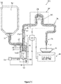
- FIG. 1 to 3 illustrate a first embodiment of an apparatus 10 for dispensing a flowable product from a collapsible container 12.
- the collapsible container 12 is typically an air-tight pouch, for example a foil pouch, and comprises an air-tight cavity 14 containing the flowable product.
- the air-tight cavity 14 is filled with a desired flowable product, for example by a product manufacturer, before the air-tight cavity 14 is sealed.
- the collapsible container 12 includes an opening 16 which allows the flowable product to be delivered from the air-tight cavity 14 when the collapsible container 12 is connected to the apparatus 10.
- the apparatus 10 comprises a reservoir 18 having a chamber 20 for receiving and storing flowable product delivered from the connected collapsible container 12.
- the chamber 20 includes a product inlet 22 which is connected to the opening 16 so that flowable product can be delivered into the chamber 20 from the air-tight cavity 14 of the collapsible container 12.
- the chamber 20 also includes a product outlet 24 through which flowable product can be delivered from the chamber 20.
- the apparatus 10 includes a conduit 26 having a first end 28 connected to the product outlet 24 and a second end 30 provided with a dispensing outlet 32 through which the flowable product can be dispensed.
- a dispensing pump 34 is provided to convey the flowable product from the product outlet 24 and along the conduit 26 from the first end 28 towards the second end 30.
- the dispensing pump 34 is a peristaltic pump having a stator 36 and a rotor 38 and the conduit 26 comprises a flexible material which can be compressed.
- stator 36 and the rotor 38 cooperate to compress the conduit 26 and as the rotor 38 rotates relative to the stator 36, flowable product is conveyed along the conduit 26 from the first end 28 towards the second end 30 by peristaltic action.
- the rotor 38 is typically engaged by, and driven by, an external rotary drive (not shown), for example a stepper motor.
- the apparatus 10 may include a receptacle 40 into which the flowable product is dispensed from the dispensing outlet 32.
- the receptacle 40 may be associated with a load cell 42 which is arranged to determine the mass of flowable product dispensed into the receptacle 40 from the dispensing outlet 32.
- the apparatus 10 includes a control unit 44.
- the control unit 44 is arranged to receive a load measurement signal from the load cell 42 and to control the operation of the dispensing pump 34, for example by controlling the operation of the external rotary drive, based on the load measurement signal received from the load cell 42.
- the control unit 44 may receive a control signal indicating a desired mass of flowable product that needs to be dispensed into the receptacle 40.
- a desired mass of flowable product may be selected to achieve a desired hair colour.
- the control unit 44 is arranged to control the dispensing pump 34 to dispense the predetermined mass of flowable product based on the control signal and the load measurement signal received from the load cell 42.
- the control unit 44 terminates the operation of the dispensing pump 34 to prevent further flowable product from being dispensed.
- the load measurement signal from the load cell 42 acts as a feedback control signal for the control unit 44 enabling it to control the operation of the dispensing pump 34 and thereby dispense accurate quantities of flowable product into the receptacle 40.
- the apparatus 10 further comprises a piston 46 which is positioned inside the chamber 20 and which is movable inside the chamber 20 to vary the internal volume of the chamber 20.
- the piston 46 is movable between a first position shown in Figure 1 which defines a maximum chamber volume and a second position shown in Figure 3 which defines a minimum chamber volume. When the piston 46 is in the second position, the chamber 20 is substantially devoid of flowable product.
- FIG. 1 A normal operating state of the apparatus 10 is shown in Figure 1 , in which the piston 46 is in the first position and the chamber volume is at its maximum.
- the chamber 20 is filled with flowable product from the connected collapsible container 12 and the dispensing pump 34 is selectively operated, by the control unit 44, to dispense desired quantities of flowable product into the receptacle 40 in the manner generally described above.
- the pumping forces suck flowable product from the air-tight cavity 14 in the collapsible container 12 through the chamber 20 and along the conduit 26 to the dispensing outlet 32, where the flowable product is dispensed into the receptacle 40.
- a suction force is applied to a contact surface 48 of the piston 46 which is in contact with the flowable product inside the chamber 20, through the medium of the flowable product.
- the piston 46 is retained in the first position by a retainer 50 which, in the illustrated embodiment, comprises a magnet assembly 52 comprising first and second magnets 54, 56 having opposite polarities.
- the magnetic strength of the first and second magnets 54, 56 is selected such that the predetermined retaining force is greater than the suction force applied to the contact surface 48 of the piston 46 by the dispensing pump 34 when the connected collapsible container 12 contains flowable product that can be delivered through the chamber 20 and into the conduit 26 via the product outlet 24.
- the piston 46 is always securely retained in the first position illustrated in Figure 1 by the magnet assembly 52.
- the apparatus 10 comprises a transducer 58, for example in the form of a limit switch, which is arranged to detect when movement of the piston 46 from the first position commences and to transmit a detection signal to the control unit 44.
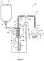
- the control unit 44 receives the detection signal from the transducer 58, the control unit 44 generates an alert, for example a visual and/or an audible alert, thereby prompting the user to disconnect the empty collapsible container 12 and to connect a replacement collapsible container 12 containing a fresh supply of flowable product.
- a user does not need to wait until the flowable product has been dispensed from the chamber 20 via the product outlet 24 before connecting a replacement collapsible container 12 which contains a fresh supply of flowable product.
- a replacement collapsible container 12 can be connected to the product inlet 22 at any time after the user has been alerted by the control unit 44 that movement of the piston 46 from the first position towards the second position has commenced, in other words that the connected collapsible container 12 is empty.
- the apparatus 10 includes a transducer 60, typically a proximity sensor such as a Hall effect sensor, which is arranged to detect when the piston 46 reaches the second position and to send a detection signal to the control unit 44.
- the receipt of the detection signal by the control unit 44 confirms that substantially all of the flowable product available in the chamber 20 has been dispensed.
- the control unit 44 Upon receiving the detection signal from the transducer 60, the control unit 44 is arranged to control the operation of a vacuum pump 62 so that it applies a suction force to a surface 64 of the piston 46 opposite to the contact surface 48 to thereby move the piston 46 from the second position to the first position.
- first and second magnets 54, 56 also cooperate to retain the piston 46 in the first position and the apparatus 10 returns to the normal operating state described above until such time as the supply of flowable product in the connected collapsible container 12 is again fully depleted and movement of the piston 46 from the first position to the second position thereby commences.
- the apparatus 10 has been described as comprising only one reservoir 18 and associated component parts and a corresponding dispensing pump 34, it will be understood by one of ordinary skill in the art that the apparatus 10 typically comprises a plurality of reservoirs 18 and associated component parts and a plurality of corresponding dispensing pumps 34 in combination with a single control unit 44 and load cell 42.
- a plurality of collapsible containers 12 containing different flowable products are each connected to a respective one of the reservoirs 18 and each dispensing pump 34 is arranged to be controlled by the control unit 44, based on the control signal and the load measurement signal received from the load cell 42, to dispense a predetermined quantity of each flowable product into the receptacle 40.
- the dispensed flowable products can be mixed together in the receptacle 40, for example to enable a desired hair colour to be obtained when the mixture of flowable products is applied to a client's hair.
- the apparatus 10 operates in the manner described above to dispense flowable product from a respective reservoir chamber 20 when the supply of flowable product in any one of the connected collapsible containers 12 is fully depleted and further flowable product cannot be dispensed from the respective air-tight cavity 14 inside a connected collapsible container 12.
- Figures 4 to 6 illustrate part of a second embodiment, not within the scope of the claims, of an apparatus 70 for dispensing a flowable product from a collapsible container 12 which is similar to the apparatus 10 shown in Figures 1 to 3 and in which corresponding components are identified using corresponding reference numerals.
- the apparatus 70 is shown connected to a collapsible container 12 housed in a rigid outer carton 72, thereby forming what is commonly known as a bag-in-box container.
- a rigid outer carton 72 is, however, not essential and could be omitted.
- the collapsible container 12 illustrated in Figures 1 to 3 could be housed in a rigid outer carton.
- the collapsible container 12 illustrated in Figures 4 to 6 has an air-tight cavity 14 containing a flowable product and an opening 16 which allows the flowable product to be delivered from the air-tight cavity 14 when the collapsible container 12 is connected to the apparatus 70.
- the apparatus 70 comprises a reservoir 18 having a chamber 20 for receiving and storing flowable product delivered from the air-tight cavity 14 of the connected collapsible container 12.
- the chamber 20 includes a product inlet 22 which is connected to the opening 16 so that flowable product can be delivered into the chamber 20 from the air-tight cavity 14 of the collapsible container 12.
- the chamber 20 also includes a product outlet 24 through which flowable product can be delivered from the chamber 20 and into a conduit 26 having a first end 28 connected to the product outlet 24 and a second end (not shown) having a dispensing outlet.
- a detector 68 for example in the form of a switch, may be provided to detect when a collapsible container 12 is connected to the apparatus 70.
- the apparatus 70 comprises a piston 74 which is positioned inside the chamber 20 and which is movable linearly inside the chamber 20 to vary the internal volume of the chamber 20.
- the piston 74 is movable between a first position shown in Figure 4 which defines a maximum chamber volume and a second position which defines a minimum chamber volume.
- the chamber 20 is substantially devoid of flowable product.
- movement of the piston 74 towards the second position dispenses flowable product from the chamber 20 via the product outlet 24 and occurs during a dispense cycle.
- movement of the piston 74 towards the first position delivers flowable product from the air-tight cavity 14 of a connected collapsible container 12 into the chamber 20 to fill the chamber 20 with flowable product.
- the apparatus 70 comprises a linear actuator 76 for controlling the movement of the piston 74 inside the chamber 20 between the first and second positions.
- the linear actuator 76 comprises an electric motor 78, typically a stepper motor, and a leadscrew 80.
- the electric motor 78 and leadscrew 80 may be arranged in any suitable manner to convert rotational motion of the electric motor 78 into linear movement of the leadscrew 80.
- the leadscrew 80 may cooperate with a guide 81 to prevent rotation of the leadscrew 80.
- the apparatus 70 includes a receptacle 40 into which flowable product is dispensed, a load cell 42 and a control unit 44.
- the apparatus 70 operates in a similar way to the apparatus 10 illustrated in Figures 1 to 3 to dispense a predetermined mass of flowable product into the receptacle 40 and the dispensing operation is controlled by the control unit 44 based on the load measurement signal received from the load cell 42.
- the operation of the linear actuator 76, and hence the movement of the piston 74 between the first and second positions, is controlled by the control unit 44.
- the control unit 44 transmits a fill control signal to the linear actuator 76 to operate the linear actuator 76 and thereby move the piston 74 towards the first position, e.g. from the second position or from a position intermediate the first and second positions, to thereby deliver flowable product from the air-tight cavity 14 of a connected collapsible container 12 into the chamber 20.
- the control unit 44 transmits a dispense control signal to the linear actuator 76 to operate the linear actuator 76 and thereby move the piston 74 towards the second position to thereby convey flowable product from the chamber 20 via the product outlet 24.
- the apparatus 70 comprises a one-way inlet valve 82 at the product inlet 22.
- the one-way inlet valve 82 typically comprising a closing member 82a positioned inside a valve body 82b, is arranged to adopt an open configuration during movement of the piston 74 towards the first position, thereby allowing flowable product to be delivered from the air-tight cavity 14 of a connected collapsible container 12 into the chamber 20 during the fill cycle.
- the one-way inlet valve 82 is arranged to adopt a closed configuration during movement of the piston 74 towards the second position.
- the closed configuration adopted by the one-way inlet valve 82 prevents the flowable product from flowing back into the air-tight cavity 14 of a connected collapsible container 12.
- the apparatus 70 also comprises a one-way outlet valve 84 at the product outlet 24.
- the one-way outlet valve 84 typically comprising a closing member 84a positioned inside a valve body 84b, is arranged to adopt a closed configuration during movement of the piston towards the first position, thereby ensuring that only flowable product from the air-tight cavity 14 of a connected collapsible container 12 is delivered to the chamber 20 during the fill cycle to thereby re-fill the chamber 20.
- the one-way outlet valve 84 is conversely arranged to adopt an open configuration during movement of the piston towards the second position, thereby enabling flowable product to be conveyed from the chamber 20 via the product outlet 24 during the dispense cycle.
- the one-way outlet valve 84 advantageously comprises a valve body 84b with an elongated bore 85 along which the closing member 84a is movable between a closed position shown in Figure 4 and a fully open position shown in Figure 5 .
- the closing member 84a is urged from the closed position shown in Figure 4 to the fully open position shown in Figure 5 by the flowable product as it is conveyed from the dispensing outlet 24.
- the piston 74 is moved by the linear actuator 76 towards the first position during the fill cycle, the closing member 84a is urged from the fully open position shown in Figure 5 to the closed position shown in Figure 6 .
- the closing member 84a moves towards the closed position along the elongated bore, it induces a reverse flow downstream of the one-way outlet valve 84 in the conduit 26 and there is a momentary delay before it reaches the closed position.
- the reverse flow and associated delay advantageously sucks flowable product at the dispensing outlet 32 back into the conduit 26, thereby minimising the risk that flowable product at the dispensing outlet 32 will fall into the receptacle 40 in an uncontrolled manner or that flowable product at the dispensing outlet 32 will be subject to degradation, e.g., due to bacterial attack.
- the apparatus 70 is shown in Figure 4 in a primed state in which the piston 74 is in the first position and the chamber volume is at its maximum.
- the chamber 20 is filled with flowable product from the air-tight cavity 14 of a connected collapsible container 12 by implementing the fill cycle described above.
- the apparatus 70 comprises a detector 86, for example in the form of a limit switch, which detects when the piston 74 is in the first position and sends a detection signal to the control unit 44.
- the control unit 44 terminates the operation of the linear actuator 76, for example by interrupting the electrical supply to the electric motor 78, to retain the piston 74 in the first position.
- an end of the leadscrew 80 abuts the detector 86 when the piston 74 is in the first position, but it will be understood that other arrangements are possible.
- control unit 44 When the control unit 44 receives a control signal indicating that a desired mass of flowable product needs to be dispensed into the receptacle 40, the control unit 44 initiates the dispense cycle by controlling the electric motor 78 to rotate the leadscrew 80 and thereby move the piston 74 inside the chamber 20 towards the second position. As soon as the control unit 44 determines that the dispense cycle is complete based on the load measurement signal received from the load cell 42, the control unit 44 initiates the fill cycle by controlling the electric motor 78 to rotate the leadscrew 80 in the opposite direction and thereby move the piston 74 inside the chamber 20 from its position at the end of the dispense cycle back to the first position.
- the fill cycle can be executed by the control unit 44 in the manner described above, to return the piston 74 to the first position, provided that there is sufficient flowable product inside the air-tight cavity 14 of a connected collapsible container 12 to completely re-fill the chamber 20.
- a vacuum is generated and the chamber 20 becomes pressurised as the piston 74 is moved by the linear actuator 76 towards the first position.
- the electric motor 78 experiences an increased load as it attempts to return the piston 74 to the first position.
- the increased load experienced by the electric motor 78 causes an increase in the drive current that must be supplied to the electric motor 78 to ensure continued movement of the piston 74 towards the first positon.
- the increase in drive current is indicative of the fact that the supply of flowable product in the air-tight cavity 14 of a connected collapsible container 12 is depleted and that a replacement collapsible container 12 needs to be connected to the apparatus 70.
- the control unit 44 continuously monitors the drive current supplied to the electric motor 78 and upon detecting an increase in the drive current above a predetermined value, the control unit 44 generates a visual and/or an audible alert which notifies a user that the connected collapsible container 12 is empty and thereby prompts the user to connect a replacement collapsible container 12 containing a further supply of flowable product.
- the control unit 44 may also interrupt the electrical supply to the electric motor 78 when the monitored drive current exceeds the predetermined value, to thereby disable the electric motor 78.
- the apparatus 70 may be arranged so that the volume of the chamber 20, when the piston 74 is in the first position, comprises a primary dispense volume 88 and a surplus dispense volume 90.
- the primary dispense volume 88 is notionally equal to a maximum dispense volume that can be demanded by the control unit 44 during a single dispense cycle. It is, however, possible that air bubbles may be present inside the chamber 20 or inside other component parts of the apparatus 70 and, hence, the provision of the surplus dispense volume 90 ensures that the maximum dispense volume can be delivered from the product outlet 24 during the dispense cycle when the piston 74 is initially in the first position.
- the control unit 44 when the control unit 44 detects that the drive current to the electric motor 78 has exceeded the predetermined level and that the piston 74 has not returned to the first position, the control unit 44 is arranged so that it will not execute a dispense cycle.
- a dispense cycle cannot be reliably executed because the total volume of flowable product in the chamber 20 is less than the maximum dispense volume that can be demanded by the control unit 44 during a single dispense cycle. Thus, a dispense cycle cannot be reliably executed unless the piston 74 is in the first position.
- the alert generated by the control unit 44 prompts a user to take immediate action to connect a replacement collapsible container 12 to the apparatus 70.
- the apparatus 70 may be arranged so that the volume of the chamber 20, when the piston 74 is in the first position, comprises multiple primary dispense volumes 88.
- Each primary dispense volume 88 is notionally equal to a maximum dispense volume that can be demanded by the control unit 44 during a single dispense cycle.
- the control unit 44 when the control unit 44 detects that the drive current to the electric motor 78 has exceeded the predetermined level and that the piston 74 has not returned to the first position, the control unit 44 is arranged determine the volume of flowable product remaining in the chamber 20 based on the position of the piston 74 inside the chamber 20. If the detected position indicates that the volume of flowable product remaining in the chamber 20 is greater than the maximum dispense volume that can be demanded by the control unit 44 during a single dispense cycle, the control unit 44 will permit one or more further dispense cycles to be executed prior to connection of a replacement collapsible container 12. It will, therefore, be understood that the chamber 20 provides a reserve volume of flowable product that is available for dispensing.
- the control unit 44 will not execute a further dispense cycle until a replacement collapsible container 12 has been connected to the apparatus 70 thereby enabling a fill cycle to be executed so that the chamber 20 is re-filled with flowable product from the air-tight cavity 14 of the connected collapsible container 12.
- FIGS 7 to 9 illustrate part of a third embodiment, not within the scope of the claims, of an apparatus 94 for dispensing a flowable product from a collapsible container 12 which is similar to the apparatus 70 shown in Figures 4 to 6 and in which corresponding components are identified using corresponding reference numerals.
- the chamber 20 is dimensioned so that its volume is at least equal to the volume of flowable product stored in the air-tight cavity 14 of the connected collapsible container 12.
- the piston 74 is initially controlled by the linear actuator 76 to move to the second position shown in Figure 7 , thereby ensuring that the chamber 20 is completely devoid of flowable product.
- a collapsible container 12 whose air-tight cavity 14 is full of flowable product, is connected to the apparatus 94.
- the presence of a collapsible container 12 is detected by the detector 68 and the control unit 44 then initiates a fill cycle.
- the control unit 44 controls the linear actuator 76 to move the piston 74 from the second position shown in Figure 7 to the first position shown in Figure 8 and in doing so, the entire contents of the flowable product are conveyed from the air-tight cavity 14 into the chamber 20.
- control unit 44 detects that the motor drive current has increased above a predetermined value, the control unit 44 interrupts the electrical supply to the electric motor 78 to thereby disable it. In addition, the control unit 44 generates a visual and/or an audible alert to notify a user that the connected collapsible container 12 is empty and that a replacement collapsible container 12 needs to be connected to the apparatus 94.
- This arrangement advantageously allows the detector 86 used with the apparatus 70 of Figures 4 to 6 to be omitted, because the increase in motor drive current above a predetermined value is used by the control unit 44 to determine that the piston 74 has been returned to the first position by the linear actuator 76.
- the control unit 44 is capable of performing several dispense cycles prior to connection of a replacement collapsible container 12 containing a further supply of flowable product. The dispense cycles are carried out in the manner described above with reference to Figures 4 to 6 .
- the control unit 44 is arranged to determine the volume of flowable product remaining in the chamber 20 by detecting the position of the piston 74 inside the chamber 20. When the detected position of the piston 74 indicates that the volume of flowable product remaining in the chamber 20 is less than the maximum dispense volume that can be demanded by the control unit 44 during a single dispense cycle, the control unit 44 will not execute a further dispense cycle. Provided that a replacement collapsible container 12 has been connected to the apparatus 94, the control unit 44 will then execute the fill cycle so that the chamber 20 is re-filled with flowable product from the air-tight cavity 14 of the connected collapsible container 12.
- Figures 10 to 13 illustrate a fourth embodiment of an apparatus 100 for dispensing a flowable product from a collapsible container 12 which is similar to the apparatus 10 shown in Figures 1 to 3 and in which corresponding components are identified using corresponding reference numerals.
- the apparatus 100 comprises a reservoir 18 having a chamber 20 for receiving and storing flowable product delivered from the connected collapsible container 12.
- the chamber 20 includes a product inlet 22 which is connected to the opening 16 so that flowable product can be delivered into the chamber 20 from the air-tight cavity 14 of the collapsible container 12.
- the chamber 20 also includes a product outlet 24 through which flowable product can be delivered from the chamber 20 during operation of the dispensing pump 34 and into the receptacle 40 via the dispensing outlet 32 as already described in detail with reference to Figures 1 to 3 .
- the apparatus 100 comprises a piston 102 which is positioned inside the chamber 20 and which is movable inside the chamber 20 to vary the internal volume of the chamber 20.
- the piston 102 is movable between a first position shown in Figures 10 and 13 which defines a maximum chamber volume and a second position (not shown) which defines a minimum chamber volume. When the piston 102 is in the second position, the chamber 20 is substantially devoid of flowable product.
- FIG. 10 and 13 A normal operating state of the apparatus 100 is shown in Figures 10 and 13 , in which the piston 102 is in the first position and the chamber volume is at its maximum.
- the chamber 20 is filled with flowable product from the connected collapsible container 12 and the dispensing pump 34 is selectively operated, by the control unit 44, to dispense desired quantities of flowable product into the receptacle 40 in the manner generally described above.
- the pumping forces suck flowable product directly from the chamber 20 and along the conduit 26 to the dispensing outlet 32, where the flowable product is dispensed into the receptacle 40.
- a suction force is applied to a contact surface 48 of the piston 102 which is in contact with the flowable product inside the chamber 20, through the medium of the flowable product.
- the applied suction force moves the piston 102 from the first position illustrated in Figures 10 and 13 towards a second position until the operation of the dispensing pump 34 is terminated by the control unit 44. It will be understood that the final position of the piston 102 in the chamber 20 at the end of the dispensing operation, for example as shown in Figure 11 , will be dependent upon the volume of flowable product that is delivered from the chamber 20 during operation of the dispensing pump 34.
- the piston 102 includes a hollow piston rod 108 which is slidably received in a linear guide 110.
- the hollow piston rod 108 has inlet ports 112 at a first end and an outlet port 114 at a second end.
- the inlet and outlet ports 112, 114 enable flowable product to be conveyed from the chamber 20 and into the conduit 26 via the product outlet 24 during movement of the piston 102 towards the second position during the dispensing operation.
- control unit 44 determines that the predetermined mass of flowable product has been delivered from the chamber 20 via the product outlet 24
- the control unit 44 is arranged to control the operation of a vacuum pump 104 so that it applies a suction force to a surface 64 of the piston 102 opposite to the contact surface 48 to thereby move the piston 102 from its final position at the end of the dispensing operation (as shown by way of example in Figure 11 ) to the first position illustrated in Figures 10 and 13 .
- a transducer 106 such as a limit switch or a micro switch, which is contacted by the piston 102 and a detection signal is transmitted to the control unit 44 by the transducer 106, causing the control unit 44 to cease operation of the vacuum pump 104 and to open a vent valve (not shown) to relieve pressure, and hence suction force, acting on the piston surface 64 and to allow it to vent to atmosphere.
- the detection signal transmitted by the transducer 106 to the control unit 44 indicates that the apparatus 100 is again ready for use to dispense further flowable product from the chamber 20 in the manner described above.
- control unit 44 determines that the piston 102 has not returned to the first position and, therefore, that the connected collapsible container 12 is empty and that further flowable product cannot be dispensed.
- the control unit 44 then generates an alert, for example a visual and/or an audible alert, thereby prompting the user to disconnect the empty collapsible container 12 and to connect a replacement collapsible container 12 containing a fresh supply of flowable product.
- the vacuum pump 104 can be operated by the control unit 44 to return the piston 102 to the first position to thereby refill the chamber 20 with flowable product and enable further dispensing operations to be performed in the manner described above.
- Figures 14 to 17 illustrate a fifth embodiment, not covered by the claims, of an apparatus 120 for dispensing a flowable product from a collapsible container 12 which is similar to the apparatus 70 shown in Figures 4 to 6 and in which corresponding components are identified using corresponding reference numerals.
- the apparatus 120 comprises a reservoir 18 having a chamber 20 for receiving and storing flowable product delivered from the air-tight cavity 14 of the connected collapsible container 12.
- the chamber 20 includes a product inlet 22 which is connected to the opening 16 so that flowable product can be delivered into the chamber 20 from the air-tight cavity 14 of the collapsible container 12.
- the chamber 20 also includes a product outlet 24 through which flowable product can be delivered from the chamber 20 and into a conduit 26 having a first end 28 connected to the product outlet 24 and a second end 30 having a dispensing outlet 32.
- the apparatus 120 comprises a piston 122 which is positioned inside the chamber 20 and which is movable linearly inside the chamber 20 to vary the internal volume of the chamber 20.
- the piston 122 is movable between a first position shown in Figures 14 and 17 which defines a maximum chamber volume and a second position which defines a minimum chamber volume.
- the chamber 20 is substantially devoid of flowable product.
- movement of the piston 122 towards the second position dispenses flowable product from the chamber 20 via the product outlet 24 and occurs during a dispense cycle.
- movement of the piston 122 towards the first position delivers flowable product from the air-tight cavity 14 of a connected collapsible container 12 into the chamber 20 to fill the chamber 20 with flowable product and occurs during a fill cycle.
- the piston 102 includes a hollow piston rod 108 which is slidably received in a linear guide 110.
- the hollow piston rod 108 has inlet ports 112 at a first end and an outlet port 114 at a second end.
- the inlet and outlet ports 112, 114 enable flowable product to be conveyed from the chamber 20 and into the conduit 26 via the product outlet 24 during movement of the piston 102 towards the second position during the dispense cycle.
- the apparatus 120 comprises a linear actuator 76 for controlling the movement of the piston 122 inside the chamber 20 between the first and second positions.
- the linear actuator 76 comprises an electric motor 78, typically a stepper motor, and a leadscrew 80.
- the electric motor 78 and leadscrew 80 may be arranged in any suitable manner to convert rotational motion of the electric motor 78 into linear movement of the leadscrew 80.
- the leadscrew 80 may cooperate with a guide 81 to prevent rotation of the leadscrew 80.
- the apparatus 120 includes a receptacle 40 into which flowable product is dispensed, a load cell 42 and a control unit 44.
- the apparatus 120 operates in a similar way to the apparatus 70 illustrated in Figures 4 to 6 to dispense a predetermined mass of flowable product into the receptacle 40 and the dispensing operation is controlled by the control unit 44 based on the load measurement signal received from the load cell 42.
- the operation of the linear actuator 76, and hence the movement of the piston 122 between the first and second positions, is controlled by the control unit 44.
- the control unit 44 transmits a fill control signal to the linear actuator 76 to operate the linear actuator 76 and thereby move the piston 122 towards the first position, e.g. from the second position or from a position intermediate the first and second positions, to thereby deliver flowable product from the air-tight cavity 14 of a connected collapsible container 12 into the chamber 20.
- the control unit 44 transmits a dispense control signal to the linear actuator 76 to operate the linear actuator 76 and thereby move the piston 122 towards the second position to thereby convey flowable product from the chamber 20 via the product outlet 24.
- the apparatus 120 comprises an inlet valve 124 positioned upstream of the product inlet 22.
- the inlet valve 124 comprises an electromechanical valve, for example a solenoid valve, which can be commanded by the control unit 44 to move between an open position and a closed position.
- the inlet valve 124 is commanded by the control unit 44 to adopt the open position during movement of the piston 122 towards the first position, thereby allowing flowable product to be delivered from the air-tight cavity 14 of a connected collapsible container 12 into the chamber 20 during the fill cycle.
- the inlet valve 124 is commanded by the control unit 44 to adopt the closed position during movement of the piston 122 towards the second position.
- the closed position of the inlet valve 124 prevents the flowable product from flowing back into the air-tight cavity 14 of a connected collapsible container 12.
- the apparatus 120 also comprises an outlet valve 126 positioned downstream of the product outlet 24.
- the outlet valve 126 comprises an electromechanical valve, for example a solenoid valve, which can be commanded by the control unit 44 to move between an open position and a closed position.
- the outlet valve 126 is commanded by the control unit 44 to adopt the closed position during movement of the piston 122 towards the first position, thereby ensuring that only flowable product from the air-tight cavity 14 of a connected collapsible container 12 is delivered to the chamber 20 during the fill cycle to thereby re-fill the chamber 20.
- the outlet valve 126 is commanded by the control unit 44 to adopt the open position during movement of the piston 122 towards the second position, thereby enabling flowable product to be conveyed from the chamber 20 via the product outlet 24 during the dispense cycle.
- the apparatus 120 is shown in Figures 14 and 17 in a primed state in which the piston 122 is in the first position and the chamber volume is at its maximum.
- the chamber 20 is filled with flowable product from the air-tight cavity 14 of a connected collapsible container 12 by implementing the fill cycle described above.
- the apparatus 120 comprises a detector 86, for example in the form of a limit switch or a micro switch, which detects when the piston 122 is in the first position and sends a detection signal to the control unit 44.
- the control unit 44 terminates the operation of the linear actuator 76, for example by interrupting the electrical supply to the electric motor 78, to retain the piston 122 in the first position.
- part of the piston 122 contacts the detector 86 when the piston 122 is in the first position, but it will be understood that other arrangements are possible.
- control unit 44 When the control unit 44 receives a control signal indicating that a desired mass of flowable product needs to be dispensed into the receptacle 40, the control unit 44 initiates the dispense cycle by commanding the inlet valve 124 to move to the closed position and commanding the outlet valve 126 to move to the open position (if not already in these positions) and by controlling the electric motor 78 to rotate the leadscrew 80 and thereby move the piston 122 inside the chamber 20 towards the second position.
- the control unit 44 determines that the dispense cycle is complete based on the load measurement signal received from the load cell 42, the control unit 44 initiates the fill cycle by commanding the inlet valve 124 to move to the open position and commanding the outlet valve 126 to move to the closed position and by controlling the electric motor 78 to rotate the leadscrew 80 in the opposite direction and thereby move the piston 122 inside the chamber 20 from its position at the end of the dispense cycle back to the first position shown in Figures 14 and 17 .
- the control unit 44 interrupts the electrical supply to the electric motor 78 upon receipt of the detection signal, to thereby terminate the fill cycle and retain the piston 122 in the first position.
- the apparatus 120 is returned once again to the primed state.
- the fill cycle can be executed by the control unit 44 in the manner described above, to return the piston 122 to the first position, provided that there is sufficient flowable product inside the air-tight cavity 14 of a connected collapsible container 12 to completely re-fill the chamber 20.
- a vacuum is generated and the chamber 20 becomes pressurised as the piston 122 is moved by the linear actuator 76 towards the first position.
- the increase in pressure inside the chamber 20, for example in the order of 0.3 to 0.4 bar, is detected by a pressure transducer 128, for example a pressure switch, and a pressure signal is transmitted to the control unit 44 by the pressure transducer 128.
- the increase in pressure is indicative of the fact that the supply of flowable product in the air-tight cavity 14 of a connected collapsible container 12 is depleted and that a replacement collapsible container 12 needs to be connected to the apparatus 120.
- control unit 44 Upon receiving the pressure signal from the pressure transducer 128, the control unit 44 generates a visual and/or an audible alert which notifies a user that the connected collapsible container 12 is empty and thereby prompts the user to connect a replacement collapsible container 12 containing a further supply of flowable product.
- the control unit 44 may also interrupt the electrical supply to the electric motor 78 upon receiving the pressure signal from the pressure transducer 128, to thereby disable the electric motor 78.
- the increase in pressure inside the chamber 20 may prevent the piston 122 from being moved by the linear actuator 76 to the first position.
- the piston 122 is prevented from contacting the detector 86 and the detector 86 is, thus, unable to transmit the detection signal to the control unit 44.
- the absence of receipt of the detection signal by the controller 44 may provide further confirmation, in addition to the receipt of the pressure signal from the pressure transducer 128, that the connected collapsible container 12 is empty and requires replacement.
- the linear actuator 76 can be operated by the control unit 44 to return the piston 122 to the first position to thereby refill the chamber 20 with flowable product and enable further dispense cycles to be performed in the manner described above.
Landscapes
- Physics & Mathematics (AREA)
- Fluid Mechanics (AREA)
- General Physics & Mathematics (AREA)
- Engineering & Computer Science (AREA)
- Mechanical Engineering (AREA)
- Containers And Packaging Bodies Having A Special Means To Remove Contents (AREA)
- Nozzles (AREA)
Description
- The present disclosure relates generally to an apparatus for dispensing a flowable product. More particularly, the present disclosure relates to an apparatus for dispensing a flowable product from an air-tight cavity of a collapsible container connected to the apparatus.
- Automated dispensing apparatus are used in a wide variety of applications to enable accurate quantities of flowable products to dispensed and mixed together. One such application is in the dispensing of hair colourings and an example of an automatic dispensing apparatus for hair colourings is described in
US 2012/0048880 A1 . - Difficulties can, however, arise with known automated dispensing apparatus when the supply of one or more of the flowable products is depleted. There is, therefore, a need for an improved apparatus for dispensing a flowable product.
- The preamble of claim 1 is derivable from
WO 98/38480 A1 US 2015/0289704 A1 , which describe prior art apparatuses for dispensing a flowable product. - According to a first aspect of the present disclosure, there is provided an apparatus for dispensing a flowable product from a collapsible container comprising an air-tight cavity and an opening, the apparatus comprising:
- a reservoir comprising a chamber for storing flowable product, the chamber comprising: a product inlet for receiving flowable product delivered from the air-tight cavity of a connected collapsible container through the opening thereof; and a product outlet for the flowable product; and
- a piston positioned inside the chamber which is movable to vary the volume of the chamber;
- wherein the apparatus comprises a vacuum pump selectively operable to move the piston towards a first position defining a maximum chamber volume.
- The piston may be movable between the first position defining the maximum chamber volume and a second position defining a minimum chamber volume.
- Flowable product is delivered from the air-tight cavity of a connected collapsible container into the chamber and is stored in the chamber. When the piston is in the first position, defining the maximum chamber volume, the chamber contains a known predetermined volume of flowable product that is available for dispensing. When the piston is in the second position defining the minimum chamber volume, the chamber may be substantially empty and substantially devoid of all flowable product.
- The apparatus may comprise a control unit.
- The control unit may be arranged to monitor a characteristic associated with the movement of the piston and may be arranged to recognise when the monitored characteristic indicates that flowable product is not available for delivery to the chamber from the air-tight cavity of a connected collapsible container. The control unit may be arranged to generate an alert upon recognising that the monitored characteristic indicates that flowable product is not available for delivery to the chamber from the air-tight cavity of a connected collapsible container. The alert could, for example, be a visual and/or an audible alert.
- Movement of the piston in the chamber between the first and second positions is affected by the availability of flowable product for delivery to the chamber from a connected collapsible container. In particular, because the flowable product is contained in an air-tight cavity within a connected collapsible container, when the supply of flowable product inside the air-tight cavity is fully depleted and an attempt is made to withdraw flowable product from the air-tight cavity, a vacuum is created (in other words the chamber is pressurised) which affects the movement of the piston in the chamber. Accordingly, by arranging the control unit to monitor a characteristic associated with the movement of the piston, the movement can be used to provide an indication that the supply of flowable product in a connected collapsible container is fully depleted and the resulting alert generated by the control unit can prompt a user to connect a replacement collapsible container which contains a further supply of flowable product.
- The apparatus may comprise a transducer, for example a limit switch or a micro switch, which may be arranged to detect when the piston is in the first position. The control unit may be arranged to monitor the movement of the piston based on a detection signal received by the control unit from the transducer. The detection signal may be indicative of movement of the piston from the first position towards the second position. Alternatively, the detection signal may indicate that the piston is in the first position.
- The apparatus may be arranged to dispense flowable product from the chamber via the product outlet during movement of the piston from the first position towards the second position. The apparatus may be arranged to deliver flowable product into the chamber from an air-tight cavity of a connected collapsible container during movement of the piston towards the first position.
- In one embodiment, movement of the piston to the first position, for example by the vacuum pump, may be prevented when the supply of flowable product in the air-tight cavity of a connected collapsible container is fully depleted. As explained above, this occurs due to pressurisation of the chamber. Thus, an alert may be generated by the control unit upon detecting that the piston has not been moved to the first position by the vacuum pump, the alert providing a user with an indication that the connected collapsible container is empty and requires replacement.
- In another embodiment, movement of the piston from the first position towards the second position may only occur when the supply of flowable product in the air-tight cavity of a connected collapsible container is fully depleted. Thus, the alert generated upon detection of movement of the piston from the first position provides a user with an indication that the connected collapsible container is empty and requires replacement. With this arrangement, the user is given sufficient time to disconnect the empty collapsible container and to connect a replacement collapsible container containing a further supply of flowable product because the flowable product in the chamber acts as a reserve volume.
- The vacuum pump may be selectively operable to move the piston from the second position to the first position and may comprise a further transducer which may be arranged to detect when the piston is in the second position and to transmit a detection signal to the control unit.
- The further transducer may be a proximity sensor and could, for example, be a Hall effect sensor.
- The control unit may be arranged to control the operation of the vacuum pump to move the piston from the second position to the first position upon receiving the detection signal from the transducer.
- When the piston is moved from the second position to the first position by the vacuum pump, flowable product from a connected collapsible container is sucked from the air-tight cavity through the opening in the collapsible container and into the chamber through the product inlet. Thus, movement of the piston from the second position to the first position fills the chamber with flowable product from the air-tight cavity of the connected collapsible container. The provision of the further transducer and the transmission of the detection signal ensures that the filling process only occurs when the piston is in the second position, defining the minimum chamber volume. This in turn ensures that substantially all flowable product in the chamber, for example from a previously connected collapsible container, is dispensed before fresh flowable product, for example from a newly connected collapsible container, is sucked into the chamber. This advantageously ensures that existing flowable product, whose properties may degrade over time, is not trapped in the chamber and mixed with fresh flowable product delivered from the air-tight cavity of the newly connected collapsible container.
- The apparatus may comprise a dispensing pump for conveying the flowable product from the product outlet. The dispensing pump may be a peristaltic pump. During operation of the dispensing pump, a suction force may be applied to a contact surface of the piston in contact with the flowable product inside the chamber. The application of the suction force to the contact surface moves the piston from the first position towards the second position as flowable product is dispensed from the chamber.
- The apparatus may comprise a retainer which may be arranged to retain the piston in the first position when the suction force applied to the contact surface of the piston is less than, or equal to, a predetermined retaining force. The retainer may comprise a magnet assembly. The magnet assembly may comprise first and second magnets having opposite polarities, e.g., a North pole and a South pole. The retainer may be arranged to release the piston and allow movement of the piston from the first position towards the second position when the suction force is greater than the predetermined retaining force.
- In some embodiments, when the collapsible container connected to the reservoir chamber contains a sufficient volume of flowable product, the pumping forces generated by the dispensing pump suck flowable product from the air-tight cavity in the connected collapsible container into the chamber via the product inlet and out of the chamber through the product outlet, and the suction force applied to the contact surface of the piston due to the operation of the dispensing pump does not exceed the predetermined retaining force. Thus, the piston remains in the first position during this normal operating state. When the supply of flowable product in the air-tight cavity of a connected collapsible container is fully depleted because it has been used up in preceding dispensing operations, the pumping forces generated by the dispensing pump increase and, hence, the suction force applied to the contact surface of the piston also increases. When the suction force attains a level which exceeds the predetermined retaining force, the retaining force exerted by the retainer on the piston is overcome and the retainer releases the piston enabling it to move from the first position towards the second position during operation of the dispensing pump. This movement allows flowable product inside the chamber to be dispensed from the product outlet even though the supply of flowable product in the air-tight cavity of the connected collapsible container is fully depleted. Thus, the apparatus is still advantageously capable of dispensing flowable product even though no flowable product is available in the connected collapsible container because the chamber contains a reserve volume of flowable product that can be dispensed from the product outlet when the supply of flowable product in the connected collapsible container is fully depleted and no further product can be delivered from the container's air-tight cavity. This means that the apparatus can still be used to dispense flowable product, and that a user does not have to immediately connect a replacement collapsible container containing further flowable product, for a period of time after the supply of flowable product in a connected collapsible container is fully depleted.
- The apparatus may comprise a conduit which may have a first end connected to the product outlet and which may have a second end through which the flowable product may be dispensed. A dispensing outlet may be provided at the second end of the conduit. The dispensing pump may be arranged to convey the flowable product along the conduit from the first end to the second end. In embodiments in which the dispensing pump is a peristaltic pump, the conduit may be a deformable conduit and the peristaltic pump may include a stator and a rotor which may cooperate to compress the deformable conduit and thereby convey the flowable product along the conduit from the first end to the second end by peristaltic action.
-
-
Figure 1 is a diagrammatic view of a first embodiment of an apparatus for dispensing a flowable product according to the present disclosure showing the operation of the apparatus when connected to a collapsible container containing flowable product; -
Figure 2 is a diagrammatic view similar toFigure 1 showing the operation of the apparatus when the supply of flowable product in the connected collapsible container is fully depleted; -
Figure 3 is a view similar toFigure 2 showing the operation of the apparatus after connection of a replacement collapsible container containing flowable product; -
Figures 4 and 5 are diagrammatic views of part of a second embodiment of an apparatus for dispensing a flowable product not within the scope of the claims showing the operation of the apparatus when connected to a collapsible container containing flowable product; -
Figure 6 is a diagrammatic view showing the operation of the apparatus ofFigures 4 and 5 when the supply of flowable product in the connected collapsible container is fully depleted; -
Figure 7 is a diagrammatic view of part of a third embodiment of an apparatus for dispensing a flowable product not within the scope of the claims showing the operation of the apparatus when connected to a collapsible container containing flowable product; -
Figure 8 is a diagrammatic view showing the operation of the apparatus ofFigure 7 when the supply of flowable product in the connected collapsible container is fully depleted, after a fill cycle; -
Figure 9 is a diagrammatic view similar toFigure 8 showing the operation of the apparatus after one or more dispense cycles and after connection of a replacement collapsible container containing flowable product; -
Figures 10 and11 are diagrammatic views of a fourth embodiment of an apparatus for dispensing a flowable product according to the present disclosure showing the operation of the apparatus when connected to a collapsible container containing flowable product; -
Figure 12 is a diagrammatic view similar toFigures 10 and11 showing the operation of the apparatus when the supply of flowable product in the connected collapsible container is fully depleted; -
Figure 13 is a view similar toFigure 12 showing the operation of the apparatus after connection of a replacement collapsible container containing flowable product; -
Figures 14 and15 are diagrammatic views of a fifth embodiment of an apparatus for dispensing a flowable product not within the scope of the claims showing the operation of the apparatus when connected to a collapsible container containing flowable product; -
Figure 16 is a diagrammatic view similar toFigures 14 and15 showing the operation of the apparatus when the supply of flowable product in the connected collapsible container is fully depleted; and -
Figure 17 is a view similar toFigure 16 showing the operation of the apparatus after connection of a replacement collapsible container containing flowable product. - Embodiments will now be described by way of example only and with reference to the accompanying drawings in which
Figures 1 to 3 illustrate a first embodiment of anapparatus 10 for dispensing a flowable product from acollapsible container 12. Thecollapsible container 12 is typically an air-tight pouch, for example a foil pouch, and comprises an air-tight cavity 14 containing the flowable product. The air-tight cavity 14 is filled with a desired flowable product, for example by a product manufacturer, before the air-tight cavity 14 is sealed. Thecollapsible container 12 includes anopening 16 which allows the flowable product to be delivered from the air-tight cavity 14 when thecollapsible container 12 is connected to theapparatus 10. - The
apparatus 10 comprises areservoir 18 having achamber 20 for receiving and storing flowable product delivered from the connectedcollapsible container 12. Thechamber 20 includes aproduct inlet 22 which is connected to theopening 16 so that flowable product can be delivered into thechamber 20 from the air-tight cavity 14 of thecollapsible container 12. Thechamber 20 also includes aproduct outlet 24 through which flowable product can be delivered from thechamber 20. - The
apparatus 10 includes aconduit 26 having afirst end 28 connected to theproduct outlet 24 and asecond end 30 provided with a dispensingoutlet 32 through which the flowable product can be dispensed. A dispensingpump 34 is provided to convey the flowable product from theproduct outlet 24 and along theconduit 26 from thefirst end 28 towards thesecond end 30. In the illustrated embodiment, the dispensingpump 34 is a peristaltic pump having astator 36 and arotor 38 and theconduit 26 comprises a flexible material which can be compressed. As will be understood by one of ordinary skill in the art, thestator 36 and therotor 38 cooperate to compress theconduit 26 and as therotor 38 rotates relative to thestator 36, flowable product is conveyed along theconduit 26 from thefirst end 28 towards thesecond end 30 by peristaltic action. Therotor 38 is typically engaged by, and driven by, an external rotary drive (not shown), for example a stepper motor. - The
apparatus 10 may include areceptacle 40 into which the flowable product is dispensed from the dispensingoutlet 32. Thereceptacle 40 may be associated with aload cell 42 which is arranged to determine the mass of flowable product dispensed into thereceptacle 40 from the dispensingoutlet 32. - The
apparatus 10 includes acontrol unit 44. Thecontrol unit 44 is arranged to receive a load measurement signal from theload cell 42 and to control the operation of the dispensingpump 34, for example by controlling the operation of the external rotary drive, based on the load measurement signal received from theload cell 42. - The
control unit 44 may receive a control signal indicating a desired mass of flowable product that needs to be dispensed into thereceptacle 40. When the flowable product is a hair colouring for example, a desired mass of flowable product may be selected to achieve a desired hair colour. Thecontrol unit 44 is arranged to control the dispensingpump 34 to dispense the predetermined mass of flowable product based on the control signal and the load measurement signal received from theload cell 42. As will be understood by one of ordinary skill in the art, when the load measurement signal received by thecontrol unit 44 from theload cell 42 indicates that the desired mass of flowable product has been dispensed into thereceptacle 40, thecontrol unit 44 terminates the operation of the dispensingpump 34 to prevent further flowable product from being dispensed. Thus, the load measurement signal from theload cell 42 acts as a feedback control signal for thecontrol unit 44 enabling it to control the operation of the dispensingpump 34 and thereby dispense accurate quantities of flowable product into thereceptacle 40. - The
apparatus 10 further comprises apiston 46 which is positioned inside thechamber 20 and which is movable inside thechamber 20 to vary the internal volume of thechamber 20. Thepiston 46 is movable between a first position shown inFigure 1 which defines a maximum chamber volume and a second position shown inFigure 3 which defines a minimum chamber volume. When thepiston 46 is in the second position, thechamber 20 is substantially devoid of flowable product. - A normal operating state of the
apparatus 10 is shown inFigure 1 , in which thepiston 46 is in the first position and the chamber volume is at its maximum. In this normal operating state, thechamber 20 is filled with flowable product from the connectedcollapsible container 12 and the dispensingpump 34 is selectively operated, by thecontrol unit 44, to dispense desired quantities of flowable product into thereceptacle 40 in the manner generally described above. - During operation of the dispensing
pump 34, the pumping forces suck flowable product from the air-tight cavity 14 in thecollapsible container 12 through thechamber 20 and along theconduit 26 to the dispensingoutlet 32, where the flowable product is dispensed into thereceptacle 40. During this dispensing operation when the dispensingpump 34 is operating, a suction force is applied to acontact surface 48 of thepiston 46 which is in contact with the flowable product inside thechamber 20, through the medium of the flowable product. When the applied suction force is less than a predetermined retaining force, thepiston 46 is retained in the first position by a retainer 50 which, in the illustrated embodiment, comprises a magnet assembly 52 comprising first andsecond magnets second magnets contact surface 48 of thepiston 46 by the dispensingpump 34 when the connectedcollapsible container 12 contains flowable product that can be delivered through thechamber 20 and into theconduit 26 via theproduct outlet 24. Thus, during the normal operating state, thepiston 46 is always securely retained in the first position illustrated inFigure 1 by the magnet assembly 52. - Referring now to
Figure 2 , when the flowable product in the connectedcollapsible container 12 has been used up in dispensing operations and the air-tight cavity 14 is empty, a vacuum is generated and the pumping forces thereby increase. As a consequence, the suction force exerted by the dispensingpump 34, through the medium of the flowable product, on thecontact surface 48 of thepiston 46 also increases. When the suction force exceeds the predetermined retaining force applied by the magnet assembly 52, thepiston 46 starts to move from the first position towards the second position as shown inFigure 2 . Consequently, theapparatus 10 can still continue to dispense flowable product even though the connectedcollapsible container 12 is empty, because thechamber 20 provides a reserve volume of flowable product that is available for dispensing. Thus, the dispensing operation is not interrupted and theapparatus 10 can continue to reliably dispense flowable product until thechamber 20 is itself empty. - In order to alert a user that the connected
collapsible container 12 is empty and needs to be replaced, theapparatus 10 comprises atransducer 58, for example in the form of a limit switch, which is arranged to detect when movement of thepiston 46 from the first position commences and to transmit a detection signal to thecontrol unit 44. When thecontrol unit 44 receives the detection signal from thetransducer 58, thecontrol unit 44 generates an alert, for example a visual and/or an audible alert, thereby prompting the user to disconnect the emptycollapsible container 12 and to connect a replacementcollapsible container 12 containing a fresh supply of flowable product. It will be understood that the amount of time remaining, after the generation of the alert by thecontrol unit 44, before the reserve supply of flowable product in thechamber 20 is used up and therefore before a newcollapsible container 12 needs to be connected to ensure uninterrupted dispensing, is dependent upon the maximum volume of thechamber 20 when thepiston 46 is in the first position. - Advantageously, a user does not need to wait until the flowable product has been dispensed from the
chamber 20 via theproduct outlet 24 before connecting a replacementcollapsible container 12 which contains a fresh supply of flowable product. On the contrary, a replacementcollapsible container 12 can be connected to theproduct inlet 22 at any time after the user has been alerted by thecontrol unit 44 that movement of thepiston 46 from the first position towards the second position has commenced, in other words that the connectedcollapsible container 12 is empty. In accordance with aspects of the present disclosure, when a replacementcollapsible container 12 is connected to theproduct inlet 22, movement of thepiston 46 from the first position continues until thepiston 46 reaches the second position shown inFigure 3 , thereby ensuring that flowable product continues to be delivered from thechamber 20 during operation of the dispensingpump 34 rather than from the air-tight cavity 14 in the newly connectedcollapsible container 12. This occurs because the pumping resistance in thechamber 20 is lower than the pumping resistance in the air-tight cavity 14. - The
apparatus 10 includes atransducer 60, typically a proximity sensor such as a Hall effect sensor, which is arranged to detect when thepiston 46 reaches the second position and to send a detection signal to thecontrol unit 44. The receipt of the detection signal by thecontrol unit 44 confirms that substantially all of the flowable product available in thechamber 20 has been dispensed. Upon receiving the detection signal from thetransducer 60, thecontrol unit 44 is arranged to control the operation of avacuum pump 62 so that it applies a suction force to asurface 64 of thepiston 46 opposite to thecontact surface 48 to thereby move thepiston 46 from the second position to the first position. During movement of thepiston 46 from the second position shown inFigure 3 back to the first position shown inFigure 1 , flowable product from the newly connectedcollapsible container 12 is drawn from the air-tight cavity 14 into thechamber 20 until thepiston 46 reaches the first position and thechamber 20 is once again filled with flowable product. Once thepiston 46 reaches the first position, this is detected by thetransducer 58 and a detection signal is transmitted to thecontrol unit 44, causing thecontrol unit 44 to cease operation of thevacuum pump 62 and to open a vent valve (not shown), for example a solenoid-controlled vent valve, to relieve pressure, and hence suction force, acting on thepiston surface 64 and to allow it to vent to atmosphere. As will be understood, the first andsecond magnets piston 46 in the first position and theapparatus 10 returns to the normal operating state described above until such time as the supply of flowable product in the connectedcollapsible container 12 is again fully depleted and movement of thepiston 46 from the first position to the second position thereby commences. - Although the
apparatus 10 has been described as comprising only onereservoir 18 and associated component parts and acorresponding dispensing pump 34, it will be understood by one of ordinary skill in the art that theapparatus 10 typically comprises a plurality ofreservoirs 18 and associated component parts and a plurality of corresponding dispensing pumps 34 in combination with asingle control unit 44 andload cell 42. In such anapparatus 10, a plurality ofcollapsible containers 12 containing different flowable products, for example one of a plurality of hair colourings, a colourless base or an additive, are each connected to a respective one of thereservoirs 18 and each dispensingpump 34 is arranged to be controlled by thecontrol unit 44, based on the control signal and the load measurement signal received from theload cell 42, to dispense a predetermined quantity of each flowable product into thereceptacle 40. In this way, the dispensed flowable products can be mixed together in thereceptacle 40, for example to enable a desired hair colour to be obtained when the mixture of flowable products is applied to a client's hair. - In such an
apparatus 10 comprising a plurality ofreservoirs 18 and associated component parts and a plurality of corresponding dispensing pumps 34, theapparatus 10 operates in the manner described above to dispense flowable product from arespective reservoir chamber 20 when the supply of flowable product in any one of the connectedcollapsible containers 12 is fully depleted and further flowable product cannot be dispensed from the respective air-tight cavity 14 inside a connectedcollapsible container 12. -
Figures 4 to 6 illustrate part of a second embodiment, not within the scope of the claims, of anapparatus 70 for dispensing a flowable product from acollapsible container 12 which is similar to theapparatus 10 shown inFigures 1 to 3 and in which corresponding components are identified using corresponding reference numerals. - The
apparatus 70 is shown connected to acollapsible container 12 housed in a rigidouter carton 72, thereby forming what is commonly known as a bag-in-box container. The provision of a rigidouter carton 72 is, however, not essential and could be omitted. Similarly, thecollapsible container 12 illustrated inFigures 1 to 3 could be housed in a rigid outer carton. Thecollapsible container 12 illustrated inFigures 4 to 6 has an air-tight cavity 14 containing a flowable product and anopening 16 which allows the flowable product to be delivered from the air-tight cavity 14 when thecollapsible container 12 is connected to theapparatus 70. - The
apparatus 70 comprises areservoir 18 having achamber 20 for receiving and storing flowable product delivered from the air-tight cavity 14 of the connectedcollapsible container 12. Thechamber 20 includes aproduct inlet 22 which is connected to theopening 16 so that flowable product can be delivered into thechamber 20 from the air-tight cavity 14 of thecollapsible container 12. Thechamber 20 also includes aproduct outlet 24 through which flowable product can be delivered from thechamber 20 and into aconduit 26 having afirst end 28 connected to theproduct outlet 24 and a second end (not shown) having a dispensing outlet. Adetector 68, for example in the form of a switch, may be provided to detect when acollapsible container 12 is connected to theapparatus 70. - The
apparatus 70 comprises apiston 74 which is positioned inside thechamber 20 and which is movable linearly inside thechamber 20 to vary the internal volume of thechamber 20. Thepiston 74 is movable between a first position shown inFigure 4 which defines a maximum chamber volume and a second position which defines a minimum chamber volume. When thepiston 74 is in the second position, thechamber 20 is substantially devoid of flowable product. As will be described in further detail below, movement of thepiston 74 towards the second position dispenses flowable product from thechamber 20 via theproduct outlet 24 and occurs during a dispense cycle. Conversely, movement of thepiston 74 towards the first position delivers flowable product from the air-tight cavity 14 of a connectedcollapsible container 12 into thechamber 20 to fill thechamber 20 with flowable product. - The
apparatus 70 comprises alinear actuator 76 for controlling the movement of thepiston 74 inside thechamber 20 between the first and second positions. In the illustrated embodiment, thelinear actuator 76 comprises anelectric motor 78, typically a stepper motor, and aleadscrew 80. Theelectric motor 78 andleadscrew 80 may be arranged in any suitable manner to convert rotational motion of theelectric motor 78 into linear movement of theleadscrew 80. Theleadscrew 80 may cooperate with aguide 81 to prevent rotation of theleadscrew 80. - Like the
apparatus 10, theapparatus 70 includes areceptacle 40 into which flowable product is dispensed, aload cell 42 and acontrol unit 44. Theapparatus 70 operates in a similar way to theapparatus 10 illustrated inFigures 1 to 3 to dispense a predetermined mass of flowable product into thereceptacle 40 and the dispensing operation is controlled by thecontrol unit 44 based on the load measurement signal received from theload cell 42. - The operation of the
linear actuator 76, and hence the movement of thepiston 74 between the first and second positions, is controlled by thecontrol unit 44. During the fill cycle, thecontrol unit 44 transmits a fill control signal to thelinear actuator 76 to operate thelinear actuator 76 and thereby move thepiston 74 towards the first position, e.g. from the second position or from a position intermediate the first and second positions, to thereby deliver flowable product from the air-tight cavity 14 of a connectedcollapsible container 12 into thechamber 20. During the dispense cycle, thecontrol unit 44 transmits a dispense control signal to thelinear actuator 76 to operate thelinear actuator 76 and thereby move thepiston 74 towards the second position to thereby convey flowable product from thechamber 20 via theproduct outlet 24. - The
apparatus 70 comprises a one-way inlet valve 82 at theproduct inlet 22. The one-way inlet valve 82, typically comprising a closingmember 82a positioned inside avalve body 82b, is arranged to adopt an open configuration during movement of thepiston 74 towards the first position, thereby allowing flowable product to be delivered from the air-tight cavity 14 of a connectedcollapsible container 12 into thechamber 20 during the fill cycle. The one-way inlet valve 82 is arranged to adopt a closed configuration during movement of thepiston 74 towards the second position. Thus, when thepiston 74 is being moved by thelinear actuator 76 towards the second position during the dispense cycle to convey flowable product from thechamber 20 via theproduct outlet 24, the closed configuration adopted by the one-way inlet valve 82 prevents the flowable product from flowing back into the air-tight cavity 14 of a connectedcollapsible container 12. - The
apparatus 70 also comprises a one-way outlet valve 84 at theproduct outlet 24. The one-way outlet valve 84, typically comprising a closingmember 84a positioned inside avalve body 84b, is arranged to adopt a closed configuration during movement of the piston towards the first position, thereby ensuring that only flowable product from the air-tight cavity 14 of a connectedcollapsible container 12 is delivered to thechamber 20 during the fill cycle to thereby re-fill thechamber 20. The one-way outlet valve 84 is conversely arranged to adopt an open configuration during movement of the piston towards the second position, thereby enabling flowable product to be conveyed from thechamber 20 via theproduct outlet 24 during the dispense cycle. - In the illustrated embodiment, it will be seen that the one-
way outlet valve 84 advantageously comprises avalve body 84b with anelongated bore 85 along which the closingmember 84a is movable between a closed position shown inFigure 4 and a fully open position shown inFigure 5 . When thepiston 74 is moved by thelinear actuator 76 towards the second position during the dispense cycle, the closingmember 84a is urged from the closed position shown inFigure 4 to the fully open position shown inFigure 5 by the flowable product as it is conveyed from the dispensingoutlet 24. Conversely, when thepiston 74 is moved by thelinear actuator 76 towards the first position during the fill cycle, the closingmember 84a is urged from the fully open position shown inFigure 5 to the closed position shown inFigure 6 . As the closingmember 84a moves towards the closed position along the elongated bore, it induces a reverse flow downstream of the one-way outlet valve 84 in theconduit 26 and there is a momentary delay before it reaches the closed position. The reverse flow and associated delay advantageously sucks flowable product at the dispensingoutlet 32 back into theconduit 26, thereby minimising the risk that flowable product at the dispensingoutlet 32 will fall into thereceptacle 40 in an uncontrolled manner or that flowable product at the dispensingoutlet 32 will be subject to degradation, e.g., due to bacterial attack. - The
apparatus 70 is shown inFigure 4 in a primed state in which thepiston 74 is in the first position and the chamber volume is at its maximum. In this primed state, thechamber 20 is filled with flowable product from the air-tight cavity 14 of a connectedcollapsible container 12 by implementing the fill cycle described above. In some embodiments, theapparatus 70 comprises adetector 86, for example in the form of a limit switch, which detects when thepiston 74 is in the first position and sends a detection signal to thecontrol unit 44. Upon receipt of the detection signal, thecontrol unit 44 terminates the operation of thelinear actuator 76, for example by interrupting the electrical supply to theelectric motor 78, to retain thepiston 74 in the first position. In the illustrated embodiment, an end of theleadscrew 80 abuts thedetector 86 when thepiston 74 is in the first position, but it will be understood that other arrangements are possible. - When the
control unit 44 receives a control signal indicating that a desired mass of flowable product needs to be dispensed into thereceptacle 40, thecontrol unit 44 initiates the dispense cycle by controlling theelectric motor 78 to rotate theleadscrew 80 and thereby move thepiston 74 inside thechamber 20 towards the second position. As soon as thecontrol unit 44 determines that the dispense cycle is complete based on the load measurement signal received from theload cell 42, thecontrol unit 44 initiates the fill cycle by controlling theelectric motor 78 to rotate theleadscrew 80 in the opposite direction and thereby move thepiston 74 inside thechamber 20 from its position at the end of the dispense cycle back to the first position. Once thepiston 74 has returned to the first position, this is detected by thedetector 86 and thecontrol unit 44 interrupts the electrical supply to theelectric motor 78, to thereby terminate the fill cycle and retain thepiston 74 in the first position. Thus, theapparatus 70 is returned once again to the primed state. - The fill cycle can be executed by the
control unit 44 in the manner described above, to return thepiston 74 to the first position, provided that there is sufficient flowable product inside the air-tight cavity 14 of a connectedcollapsible container 12 to completely re-fill thechamber 20. In the event that the flowable product inside the air-tight cavity 14 becomes fully depleted because it has been consumed in one or more preceding dispense cycles, a vacuum is generated and thechamber 20 becomes pressurised as thepiston 74 is moved by thelinear actuator 76 towards the first position. As a result, when the fill cycle is executed by thecontrol unit 44, theelectric motor 78 experiences an increased load as it attempts to return thepiston 74 to the first position. The increased load experienced by theelectric motor 78 causes an increase in the drive current that must be supplied to theelectric motor 78 to ensure continued movement of thepiston 74 towards the first positon. The increase in drive current is indicative of the fact that the supply of flowable product in the air-tight cavity 14 of a connectedcollapsible container 12 is depleted and that a replacementcollapsible container 12 needs to be connected to theapparatus 70. - The
control unit 44 continuously monitors the drive current supplied to theelectric motor 78 and upon detecting an increase in the drive current above a predetermined value, thecontrol unit 44 generates a visual and/or an audible alert which notifies a user that the connectedcollapsible container 12 is empty and thereby prompts the user to connect a replacementcollapsible container 12 containing a further supply of flowable product. Thecontrol unit 44 may also interrupt the electrical supply to theelectric motor 78 when the monitored drive current exceeds the predetermined value, to thereby disable theelectric motor 78. - In a first implementation, the
apparatus 70 may be arranged so that the volume of thechamber 20, when thepiston 74 is in the first position, comprises a primary dispensevolume 88 and a surplus dispensevolume 90. The primary dispensevolume 88 is notionally equal to a maximum dispense volume that can be demanded by thecontrol unit 44 during a single dispense cycle. It is, however, possible that air bubbles may be present inside thechamber 20 or inside other component parts of theapparatus 70 and, hence, the provision of the surplus dispensevolume 90 ensures that the maximum dispense volume can be delivered from theproduct outlet 24 during the dispense cycle when thepiston 74 is initially in the first position. - In this first implementation, when the
control unit 44 detects that the drive current to theelectric motor 78 has exceeded the predetermined level and that thepiston 74 has not returned to the first position, thecontrol unit 44 is arranged so that it will not execute a dispense cycle. A dispense cycle cannot be reliably executed because the total volume of flowable product in thechamber 20 is less than the maximum dispense volume that can be demanded by thecontrol unit 44 during a single dispense cycle. Thus, a dispense cycle cannot be reliably executed unless thepiston 74 is in the first position. In this first implementation, it will be understood that a replacementcollapsible container 12 must be connected to theapparatus 70 before further dispense cycles can be executed. Thus, the alert generated by thecontrol unit 44 prompts a user to take immediate action to connect a replacementcollapsible container 12 to theapparatus 70. - In a second implementation, the
apparatus 70 may be arranged so that the volume of thechamber 20, when thepiston 74 is in the first position, comprises multiple primary dispensevolumes 88. Each primary dispensevolume 88 is notionally equal to a maximum dispense volume that can be demanded by thecontrol unit 44 during a single dispense cycle. - In this second implementation, when the
control unit 44 detects that the drive current to theelectric motor 78 has exceeded the predetermined level and that thepiston 74 has not returned to the first position, thecontrol unit 44 is arranged determine the volume of flowable product remaining in thechamber 20 based on the position of thepiston 74 inside thechamber 20. If the detected position indicates that the volume of flowable product remaining in thechamber 20 is greater than the maximum dispense volume that can be demanded by thecontrol unit 44 during a single dispense cycle, thecontrol unit 44 will permit one or more further dispense cycles to be executed prior to connection of a replacementcollapsible container 12. It will, therefore, be understood that thechamber 20 provides a reserve volume of flowable product that is available for dispensing. - In this second implementation, if the position of the
piston 74 detected by thecontrol unit 44 indicates that the volume of flowable product remaining in thechamber 20 is less than the maximum dispense volume that can be demanded by thecontrol unit 44 during a single dispense cycle, thecontrol unit 44 will not execute a further dispense cycle until a replacementcollapsible container 12 has been connected to theapparatus 70 thereby enabling a fill cycle to be executed so that thechamber 20 is re-filled with flowable product from the air-tight cavity 14 of the connectedcollapsible container 12. -
Figures 7 to 9 illustrate part of a third embodiment, not within the scope of the claims, of anapparatus 94 for dispensing a flowable product from acollapsible container 12 which is similar to theapparatus 70 shown inFigures 4 to 6 and in which corresponding components are identified using corresponding reference numerals. - In the
apparatus 94, thechamber 20 is dimensioned so that its volume is at least equal to the volume of flowable product stored in the air-tight cavity 14 of the connectedcollapsible container 12. Thus, when thepiston 74 is in the first position shown inFigure 8 , it will be understood that thechamber 20 stores the entire contents from the air-tight cavity 14 of a connectedcollapsible container 12. - In operation, the
piston 74 is initially controlled by thelinear actuator 76 to move to the second position shown inFigure 7 , thereby ensuring that thechamber 20 is completely devoid of flowable product. Either before or after thepiston 74 has been moved to the second position, acollapsible container 12, whose air-tight cavity 14 is full of flowable product, is connected to theapparatus 94. The presence of acollapsible container 12 is detected by thedetector 68 and thecontrol unit 44 then initiates a fill cycle. Specifically, thecontrol unit 44 controls thelinear actuator 76 to move thepiston 74 from the second position shown inFigure 7 to the first position shown inFigure 8 and in doing so, the entire contents of the flowable product are conveyed from the air-tight cavity 14 into thechamber 20. - As the
piston 74 approaches the first position at the end of the fill cycle and there is no further flowable product remaining inside the air-tight cavity 14 of the connectedcollapsible container 12, a vacuum is generated inside the air-tight cavity 14 and the motor drive current increases for the reasons described earlier in this specification. When thecontrol unit 44 detects that the motor drive current has increased above a predetermined value, thecontrol unit 44 interrupts the electrical supply to theelectric motor 78 to thereby disable it. In addition, thecontrol unit 44 generates a visual and/or an audible alert to notify a user that the connectedcollapsible container 12 is empty and that a replacementcollapsible container 12 needs to be connected to theapparatus 94. This arrangement advantageously allows thedetector 86 used with theapparatus 70 ofFigures 4 to 6 to be omitted, because the increase in motor drive current above a predetermined value is used by thecontrol unit 44 to determine that thepiston 74 has been returned to the first position by thelinear actuator 76. - Because the volume of the
chamber 20 in theapparatus 94 is at least equal to the volume of flowable product stored in the air-tight cavity 14 of a connectedcollapsible container 12, it will be understood that thechamber 20 contains multiple primary dispense volumes when thepiston 74 is in the first position shown inFigure 8 . Thus, thecontrol unit 44 is capable of performing several dispense cycles prior to connection of a replacementcollapsible container 12 containing a further supply of flowable product. The dispense cycles are carried out in the manner described above with reference toFigures 4 to 6 . - As also described above with reference to
Figures 4 to 6 , thecontrol unit 44 is arranged to determine the volume of flowable product remaining in thechamber 20 by detecting the position of thepiston 74 inside thechamber 20. When the detected position of thepiston 74 indicates that the volume of flowable product remaining in thechamber 20 is less than the maximum dispense volume that can be demanded by thecontrol unit 44 during a single dispense cycle, thecontrol unit 44 will not execute a further dispense cycle. Provided that a replacementcollapsible container 12 has been connected to theapparatus 94, thecontrol unit 44 will then execute the fill cycle so that thechamber 20 is re-filled with flowable product from the air-tight cavity 14 of the connectedcollapsible container 12. -
Figures 10 to 13 illustrate a fourth embodiment of anapparatus 100 for dispensing a flowable product from acollapsible container 12 which is similar to theapparatus 10 shown inFigures 1 to 3 and in which corresponding components are identified using corresponding reference numerals. - The
apparatus 100 comprises areservoir 18 having achamber 20 for receiving and storing flowable product delivered from the connectedcollapsible container 12. Thechamber 20 includes aproduct inlet 22 which is connected to theopening 16 so that flowable product can be delivered into thechamber 20 from the air-tight cavity 14 of thecollapsible container 12. Thechamber 20 also includes aproduct outlet 24 through which flowable product can be delivered from thechamber 20 during operation of the dispensingpump 34 and into thereceptacle 40 via the dispensingoutlet 32 as already described in detail with reference toFigures 1 to 3 . - The
apparatus 100 comprises apiston 102 which is positioned inside thechamber 20 and which is movable inside thechamber 20 to vary the internal volume of thechamber 20. Thepiston 102 is movable between a first position shown inFigures 10 and13 which defines a maximum chamber volume and a second position (not shown) which defines a minimum chamber volume. When thepiston 102 is in the second position, thechamber 20 is substantially devoid of flowable product. - A normal operating state of the
apparatus 100 is shown inFigures 10 and13 , in which thepiston 102 is in the first position and the chamber volume is at its maximum. In this normal operating state, thechamber 20 is filled with flowable product from the connectedcollapsible container 12 and the dispensingpump 34 is selectively operated, by thecontrol unit 44, to dispense desired quantities of flowable product into thereceptacle 40 in the manner generally described above. - During operation of the dispensing
pump 34, the pumping forces suck flowable product directly from thechamber 20 and along theconduit 26 to the dispensingoutlet 32, where the flowable product is dispensed into thereceptacle 40. During this dispensing operation when the dispensingpump 34 is operating, a suction force is applied to acontact surface 48 of thepiston 102 which is in contact with the flowable product inside thechamber 20, through the medium of the flowable product. The applied suction force moves thepiston 102 from the first position illustrated inFigures 10 and13 towards a second position until the operation of the dispensingpump 34 is terminated by thecontrol unit 44. It will be understood that the final position of thepiston 102 in thechamber 20 at the end of the dispensing operation, for example as shown inFigure 11 , will be dependent upon the volume of flowable product that is delivered from thechamber 20 during operation of the dispensingpump 34. - The
piston 102 includes ahollow piston rod 108 which is slidably received in alinear guide 110. Thehollow piston rod 108 hasinlet ports 112 at a first end and anoutlet port 114 at a second end. The inlet andoutlet ports chamber 20 and into theconduit 26 via theproduct outlet 24 during movement of thepiston 102 towards the second position during the dispensing operation. - After the
control unit 44 determines that the predetermined mass of flowable product has been delivered from thechamber 20 via theproduct outlet 24, thecontrol unit 44 is arranged to control the operation of avacuum pump 104 so that it applies a suction force to asurface 64 of thepiston 102 opposite to thecontact surface 48 to thereby move thepiston 102 from its final position at the end of the dispensing operation (as shown by way of example inFigure 11 ) to the first position illustrated inFigures 10 and13 . During movement of thepiston 102 back to the first position and provided that there is sufficient flowable product inside the air-tight cavity 14 of a connectedcollapsible container 12 to completely re-fill thechamber 20, flowable product from thecollapsible container 12 is drawn from the air-tight cavity 14 into thechamber 20 until thepiston 102 reaches the first position and thechamber 20 is once again completely filled with flowable product. - Once the
piston 102 reaches the first position, this is detected by atransducer 106, such as a limit switch or a micro switch, which is contacted by thepiston 102 and a detection signal is transmitted to thecontrol unit 44 by thetransducer 106, causing thecontrol unit 44 to cease operation of thevacuum pump 104 and to open a vent valve (not shown) to relieve pressure, and hence suction force, acting on thepiston surface 64 and to allow it to vent to atmosphere. The detection signal transmitted by thetransducer 106 to thecontrol unit 44 indicates that theapparatus 100 is again ready for use to dispense further flowable product from thechamber 20 in the manner described above. - Referring now to
Figure 12 , when the flowable product in the connectedcollapsible container 12 has been used up in prior dispensing operations and the air-tight cavity 14 is empty, a vacuum is generated and the pumping forces thereby increase. As a consequence, during operation of thevacuum pump 104 to move thepiston 102 from its final position at the end of the dispensing operation (as shown by way of example inFigure 11 ) to the first position, the pumping forces cannot be overcome by thevacuum pump 104 and thepiston 102 cannot be returned by thevacuum pump 104 to the first position. This prevents thepiston 102 from contacting thetransducer 106 and, thus, thetransducer 106 cannot transmit a detection signal to thecontrol unit 44. In the absence of the detection signal, thecontrol unit 44 determines that thepiston 102 has not returned to the first position and, therefore, that the connectedcollapsible container 12 is empty and that further flowable product cannot be dispensed. Thecontrol unit 44 then generates an alert, for example a visual and/or an audible alert, thereby prompting the user to disconnect the emptycollapsible container 12 and to connect a replacementcollapsible container 12 containing a fresh supply of flowable product. - After connection of a replacement
collapsible container 12 containing a fresh supply of flowable product as illustrated inFigure 13 , thevacuum pump 104 can be operated by thecontrol unit 44 to return thepiston 102 to the first position to thereby refill thechamber 20 with flowable product and enable further dispensing operations to be performed in the manner described above. -
Figures 14 to 17 illustrate a fifth embodiment, not covered by the claims, of anapparatus 120 for dispensing a flowable product from acollapsible container 12 which is similar to theapparatus 70 shown inFigures 4 to 6 and in which corresponding components are identified using corresponding reference numerals. - The
apparatus 120 comprises areservoir 18 having achamber 20 for receiving and storing flowable product delivered from the air-tight cavity 14 of the connectedcollapsible container 12. Thechamber 20 includes aproduct inlet 22 which is connected to theopening 16 so that flowable product can be delivered into thechamber 20 from the air-tight cavity 14 of thecollapsible container 12. Thechamber 20 also includes aproduct outlet 24 through which flowable product can be delivered from thechamber 20 and into aconduit 26 having afirst end 28 connected to theproduct outlet 24 and asecond end 30 having a dispensingoutlet 32. - The
apparatus 120 comprises apiston 122 which is positioned inside thechamber 20 and which is movable linearly inside thechamber 20 to vary the internal volume of thechamber 20. Thepiston 122 is movable between a first position shown inFigures 14 and17 which defines a maximum chamber volume and a second position which defines a minimum chamber volume. When thepiston 122 is in the second position, thechamber 20 is substantially devoid of flowable product. As will be described in further detail below, movement of thepiston 122 towards the second position dispenses flowable product from thechamber 20 via theproduct outlet 24 and occurs during a dispense cycle. Conversely, movement of thepiston 122 towards the first position delivers flowable product from the air-tight cavity 14 of a connectedcollapsible container 12 into thechamber 20 to fill thechamber 20 with flowable product and occurs during a fill cycle. - The
piston 102 includes ahollow piston rod 108 which is slidably received in alinear guide 110. Thehollow piston rod 108 hasinlet ports 112 at a first end and anoutlet port 114 at a second end. The inlet andoutlet ports chamber 20 and into theconduit 26 via theproduct outlet 24 during movement of thepiston 102 towards the second position during the dispense cycle. - The
apparatus 120 comprises alinear actuator 76 for controlling the movement of thepiston 122 inside thechamber 20 between the first and second positions. In the illustrated embodiment, thelinear actuator 76 comprises anelectric motor 78, typically a stepper motor, and aleadscrew 80. Theelectric motor 78 andleadscrew 80 may be arranged in any suitable manner to convert rotational motion of theelectric motor 78 into linear movement of theleadscrew 80. Theleadscrew 80 may cooperate with aguide 81 to prevent rotation of theleadscrew 80. - Like the apparatus described above, the
apparatus 120 includes areceptacle 40 into which flowable product is dispensed, aload cell 42 and acontrol unit 44. Theapparatus 120 operates in a similar way to theapparatus 70 illustrated inFigures 4 to 6 to dispense a predetermined mass of flowable product into thereceptacle 40 and the dispensing operation is controlled by thecontrol unit 44 based on the load measurement signal received from theload cell 42. - The operation of the
linear actuator 76, and hence the movement of thepiston 122 between the first and second positions, is controlled by thecontrol unit 44. During the fill cycle, thecontrol unit 44 transmits a fill control signal to thelinear actuator 76 to operate thelinear actuator 76 and thereby move thepiston 122 towards the first position, e.g. from the second position or from a position intermediate the first and second positions, to thereby deliver flowable product from the air-tight cavity 14 of a connectedcollapsible container 12 into thechamber 20. During the dispense cycle, thecontrol unit 44 transmits a dispense control signal to thelinear actuator 76 to operate thelinear actuator 76 and thereby move thepiston 122 towards the second position to thereby convey flowable product from thechamber 20 via theproduct outlet 24. - The
apparatus 120 comprises aninlet valve 124 positioned upstream of theproduct inlet 22. Theinlet valve 124 comprises an electromechanical valve, for example a solenoid valve, which can be commanded by thecontrol unit 44 to move between an open position and a closed position. Theinlet valve 124 is commanded by thecontrol unit 44 to adopt the open position during movement of thepiston 122 towards the first position, thereby allowing flowable product to be delivered from the air-tight cavity 14 of a connectedcollapsible container 12 into thechamber 20 during the fill cycle. Theinlet valve 124 is commanded by thecontrol unit 44 to adopt the closed position during movement of thepiston 122 towards the second position. Thus, when thepiston 122 is being moved by thelinear actuator 76 towards the second position during the dispense cycle to convey flowable product from thechamber 20 via theproduct outlet 24, the closed position of theinlet valve 124 prevents the flowable product from flowing back into the air-tight cavity 14 of a connectedcollapsible container 12. - The
apparatus 120 also comprises anoutlet valve 126 positioned downstream of theproduct outlet 24. Theoutlet valve 126 comprises an electromechanical valve, for example a solenoid valve, which can be commanded by thecontrol unit 44 to move between an open position and a closed position. Theoutlet valve 126 is commanded by thecontrol unit 44 to adopt the closed position during movement of thepiston 122 towards the first position, thereby ensuring that only flowable product from the air-tight cavity 14 of a connectedcollapsible container 12 is delivered to thechamber 20 during the fill cycle to thereby re-fill thechamber 20. Theoutlet valve 126 is commanded by thecontrol unit 44 to adopt the open position during movement of thepiston 122 towards the second position, thereby enabling flowable product to be conveyed from thechamber 20 via theproduct outlet 24 during the dispense cycle. - The
apparatus 120 is shown inFigures 14 and17 in a primed state in which thepiston 122 is in the first position and the chamber volume is at its maximum. In this primed state, thechamber 20 is filled with flowable product from the air-tight cavity 14 of a connectedcollapsible container 12 by implementing the fill cycle described above. Theapparatus 120 comprises adetector 86, for example in the form of a limit switch or a micro switch, which detects when thepiston 122 is in the first position and sends a detection signal to thecontrol unit 44. Upon receipt of the detection signal, thecontrol unit 44 terminates the operation of thelinear actuator 76, for example by interrupting the electrical supply to theelectric motor 78, to retain thepiston 122 in the first position. In the illustrated embodiment, part of thepiston 122 contacts thedetector 86 when thepiston 122 is in the first position, but it will be understood that other arrangements are possible. - When the
control unit 44 receives a control signal indicating that a desired mass of flowable product needs to be dispensed into thereceptacle 40, thecontrol unit 44 initiates the dispense cycle by commanding theinlet valve 124 to move to the closed position and commanding theoutlet valve 126 to move to the open position (if not already in these positions) and by controlling theelectric motor 78 to rotate theleadscrew 80 and thereby move thepiston 122 inside thechamber 20 towards the second position. As soon as thecontrol unit 44 determines that the dispense cycle is complete based on the load measurement signal received from theload cell 42, thecontrol unit 44 initiates the fill cycle by commanding theinlet valve 124 to move to the open position and commanding theoutlet valve 126 to move to the closed position and by controlling theelectric motor 78 to rotate theleadscrew 80 in the opposite direction and thereby move thepiston 122 inside thechamber 20 from its position at the end of the dispense cycle back to the first position shown inFigures 14 and17 . Once thepiston 122 has returned to the first position, this is detected by thedetector 86 and thecontrol unit 44 interrupts the electrical supply to theelectric motor 78 upon receipt of the detection signal, to thereby terminate the fill cycle and retain thepiston 122 in the first position. Thus, theapparatus 120 is returned once again to the primed state. - The fill cycle can be executed by the
control unit 44 in the manner described above, to return thepiston 122 to the first position, provided that there is sufficient flowable product inside the air-tight cavity 14 of a connectedcollapsible container 12 to completely re-fill thechamber 20. In the event that the flowable product inside the air-tight cavity 14 becomes fully depleted because it has been consumed in one or more preceding dispense cycles, a vacuum is generated and thechamber 20 becomes pressurised as thepiston 122 is moved by thelinear actuator 76 towards the first position. The increase in pressure inside thechamber 20, for example in the order of 0.3 to 0.4 bar, is detected by apressure transducer 128, for example a pressure switch, and a pressure signal is transmitted to thecontrol unit 44 by thepressure transducer 128. The increase in pressure is indicative of the fact that the supply of flowable product in the air-tight cavity 14 of a connectedcollapsible container 12 is depleted and that a replacementcollapsible container 12 needs to be connected to theapparatus 120. - Upon receiving the pressure signal from the
pressure transducer 128, thecontrol unit 44 generates a visual and/or an audible alert which notifies a user that the connectedcollapsible container 12 is empty and thereby prompts the user to connect a replacementcollapsible container 12 containing a further supply of flowable product. Thecontrol unit 44 may also interrupt the electrical supply to theelectric motor 78 upon receiving the pressure signal from thepressure transducer 128, to thereby disable theelectric motor 78. - It is envisaged that the increase in pressure inside the
chamber 20 may prevent thepiston 122 from being moved by thelinear actuator 76 to the first position. In this case, thepiston 122 is prevented from contacting thedetector 86 and thedetector 86 is, thus, unable to transmit the detection signal to thecontrol unit 44. The absence of receipt of the detection signal by thecontroller 44 may provide further confirmation, in addition to the receipt of the pressure signal from thepressure transducer 128, that the connectedcollapsible container 12 is empty and requires replacement. - After connection of a replacement
collapsible container 12 containing a fresh supply of flowable product as illustrated inFigure 17 , it will be understood that thelinear actuator 76 can be operated by thecontrol unit 44 to return thepiston 122 to the first position to thereby refill thechamber 20 with flowable product and enable further dispense cycles to be performed in the manner described above. - Although exemplary embodiments have been described in the preceding paragraphs, it should be understood that various modifications may be made to those embodiments without departing from the scope of the appended claims. Thus, the breadth and scope of the claims should not be limited to the above-described exemplary embodiments.
- Any combination of the above-described features in all possible variations thereof is encompassed by the present disclosure unless otherwise indicated herein or otherwise clearly contradicted by context.
- Unless the context clearly requires otherwise, throughout the description and the claims, the words "comprise", "comprising", and the like, are to be construed in an inclusive as opposed to an exclusive or exhaustive sense; that is to say, in the sense of "including, but not limited to".
Claims (15)
- An apparatus (10, 100) for dispensing a flowable product from a collapsible container (12) comprising an air-tight cavity (14) and an opening (16), the apparatus comprising:a reservoir (18) comprising a chamber (20) for storing flowable product, the chamber (20) comprising: a product inlet (22) for receiving flowable product delivered from the air-tight cavity (14) of a connected collapsible container (12) through the opening (16) thereof; and a product outlet (24) for the flowable product; anda piston (46, 102) positioned inside the chamber (20) which is movable to vary the volume of the chamber (20);characterized in that the apparatus (10, 100) comprises a vacuum pump (62, 104) selectively operable to move the piston (46, 102) towards a first position defining a maximum chamber volume.
- An apparatus according to claim 1, wherein the piston (46, 102) is movable between the first position defining the maximum chamber volume and a second position defining a minimum chamber volume.
- An apparatus according to claim 1 or claim 2, further comprising a control unit (44).
- An apparatus according to claim 3, wherein the control unit (44) is arranged to monitor a characteristic associated with the movement of the piston (46, 102) and to recognise when the monitored characteristic indicates that flowable product is not available for delivery to the chamber (20) from the air-tight cavity (14) of a connected collapsible container (12).
- An apparatus according to claim 4, wherein the control unit (44) is arranged to generate an alert upon recognising that the monitored characteristic indicates that flowable product is not available for delivery to the chamber (20) from the air-tight cavity (14) of a connected collapsible container (12).
- An apparatus according to claim 4 or claim 5 when dependent on claims 2 and 3, wherein the apparatus comprises a transducer (58, 106) arranged to detect when the piston (46, 102) is in the first position and the control unit (44) is arranged to monitor the movement of the piston (46, 102) based on a detection signal received by the control unit (44) from the transducer (58, 106).
- An apparatus according to claims 5 and 6, wherein the detection signal is indicative of movement of the piston (46, 102) from the first position towards the second position or indicates that the piston (46, 102) is in the first position.
- An apparatus according to any of claims 2 to 7, wherein:
the vacuum pump (62) is selectively operable to move the piston (46) from the second position to the first position; and wherein the apparatus (10) further comprises:a further transducer (60) arranged to detect when the piston (46) is in the second position and to transmit a detection signal to the control unit (44);the control unit (44) being arranged to control the operation of the vacuum pump (62) to move the piston (46) from the second position to the first position upon receiving the detection signal from the further transducer (60). - An apparatus according to any preceding claim, wherein the apparatus (10, 100) comprises a dispensing pump (34) for conveying the flowable product from the product outlet (24).
- An apparatus according to claim 9, wherein, during operation of the dispensing pump (34), a suction force is applied to a contact surface (48) of the piston (46, 102) in contact with the flowable product inside the chamber (20), preferably wherein the suction force is arranged to move the piston (46, 102) from the first position towards the second position during dispensing of flowable product from the chamber (20).
- An apparatus according to claim 10, wherein the apparatus (10) comprises a retainer (50) arranged to retain the piston (46) in the first position when the suction force is less than, or equal to, a predetermined retaining force, preferably wherein the retainer (50) is arranged to release the piston (46) and allow movement of the piston (46) from the first position towards the second position when the suction force is greater than the predetermined retaining force.
- An apparatus according to claim 11, wherein the retainer (50) comprises a magnet assembly (52), preferably wherein the magnet assembly (52) comprises first and second magnets (54, 56) having opposite polarities.
- An apparatus according to any preceding claim, wherein the apparatus (10, 100) comprises a conduit (26) having a first end (28) connected to the product outlet (24) and a second end (30) through which the flowable product is dispensed, preferably wherein a dispensing outlet (32) is provided at the second end (30) of the conduit (26).
- An apparatus according to claim 13 when dependent on claim 9, wherein the dispensing pump (34) is arranged to convey the flowable product along the conduit (26) from the first end (28) to the second end (30).
- An apparatus according to any of claims 2 to 14, wherein the apparatus (10, 100) is arranged to deliver flowable product into the chamber (20) from the air-tight cavity (14) of a connected collapsible container (12) during movement of the piston (46, 102) towards the first position and/or to dispense flowable product from the chamber (20) via the product outlet (24) during movement of the piston (46, 102) from the first position towards the second position.
Applications Claiming Priority (2)
| Application Number | Priority Date | Filing Date | Title |
|---|---|---|---|
| GBGB1703549.4A GB201703549D0 (en) | 2017-03-06 | 2017-03-06 | Apparatus for dispensing a flowable product |
| PCT/GB2018/050551 WO2018162883A1 (en) | 2017-03-06 | 2018-03-05 | Apparatus for dispensing a flowable product |
Publications (2)
| Publication Number | Publication Date |
|---|---|
| EP3593095A1 EP3593095A1 (en) | 2020-01-15 |
| EP3593095B1 true EP3593095B1 (en) | 2022-12-21 |
Family
ID=58543778
Family Applications (1)
| Application Number | Title | Priority Date | Filing Date |
|---|---|---|---|
| EP18714013.2A Active EP3593095B1 (en) | 2017-03-06 | 2018-03-05 | Apparatus for dispensing a flowable product |
Country Status (6)
| Country | Link |
|---|---|
| US (1) | US10928235B2 (en) |
| EP (1) | EP3593095B1 (en) |
| DK (1) | DK3593095T3 (en) |
| ES (1) | ES2936108T3 (en) |
| GB (2) | GB201703549D0 (en) |
| WO (1) | WO2018162883A1 (en) |
Families Citing this family (4)
| Publication number | Priority date | Publication date | Assignee | Title |
|---|---|---|---|---|
| FR3054205B1 (en) * | 2016-07-22 | 2018-08-24 | Nbread-Process | DEVICE FOR DEPOSITING ACCURATE QUANTITY OF PRODUCT |
| US20210393506A1 (en) | 2018-11-06 | 2021-12-23 | Noor Al-Rifai | Fragrance blends and methods for preparation thereof |
| US12310378B2 (en) | 2020-06-29 | 2025-05-27 | Jbt Marel Corporation | Produce processing dosing system |
| US20220002137A1 (en) * | 2020-07-06 | 2022-01-06 | A. J. Antunes & Co. | Touchless flowable product dispenser |
Family Cites Families (37)
| Publication number | Priority date | Publication date | Assignee | Title |
|---|---|---|---|---|
| US3637116A (en) * | 1970-02-09 | 1972-01-25 | Russell G Rutherford | Fluid-operated piston for metering gravity fed material |
| US3981414A (en) * | 1975-04-07 | 1976-09-21 | Raymond Edward Gust | Beverage dispensing system |
| US4027785A (en) | 1976-04-12 | 1977-06-07 | Chicago Commutator, Inc. | Dual pump colorant dispenser |
| GB8704343D0 (en) * | 1987-02-24 | 1987-04-01 | Odin Dev Ltd | Dosing system |
| US5067531A (en) * | 1989-10-30 | 1991-11-26 | Kenneth Herzog | Bench top container filler |
| JPH087222B2 (en) * | 1990-01-18 | 1996-01-29 | 持田製薬株式会社 | Automatic dispensing dilution device |
| US5086403A (en) * | 1990-03-09 | 1992-02-04 | Emerson Electric Co. | Liquid leak test probe with compensation for gas in line |
| US5199604A (en) * | 1990-05-04 | 1993-04-06 | Sultan Chemists, Inc. | Irrigation system and method for delivering a selected one of multiple liquid solutions to a treatment site |
| US5356041A (en) | 1993-03-23 | 1994-10-18 | Fluid Management Limited Partnership | Dispensing apparatus having improved valving |
| US5485812A (en) * | 1995-01-26 | 1996-01-23 | Firey; Joseph C. | Multiple sources refuel mechanism |
| DK171926B1 (en) * | 1995-02-10 | 1997-08-11 | Slagteriernes Forskningsinst | Apparatus for examining flowable material and device for feeding samples |
| US5862947A (en) * | 1996-02-06 | 1999-01-26 | Bristol-Myers Squibb Company | Hair dye color selection system and method |
| GB9703918D0 (en) * | 1997-02-25 | 1997-04-16 | Weston Medical Ltd | Fluid metering dispenser |
| US5975374A (en) * | 1997-11-03 | 1999-11-02 | The Pillsbury Company | Depositor apparatus |
| EP1417035A2 (en) | 2000-07-19 | 2004-05-12 | Lenteq Europe B.V. | System for dispensing portions of various substances |
| US6905314B2 (en) * | 2001-10-16 | 2005-06-14 | Baxter International Inc. | Pump having flexible liner and compounding apparatus having such a pump |
| US6619304B2 (en) * | 2001-09-13 | 2003-09-16 | Micell Technologies, Inc. | Pressure chamber assembly including non-mechanical drive means |
| US6820763B2 (en) * | 2002-03-13 | 2004-11-23 | Sb Partnership, Inc. | Portable beverage dispensing systems |
| US11249095B2 (en) * | 2002-04-15 | 2022-02-15 | Ventana Medical Systems, Inc. | Automated high volume slide processing system |
| US20050150911A1 (en) * | 2003-12-23 | 2005-07-14 | Bach David T. | Anti-drip anti-foaming fluid dispensing system |
| US20050224523A1 (en) * | 2004-04-13 | 2005-10-13 | Advanced Technology Materials, Inc. | Liquid dispensing method and system with headspace gas removal |
| WO2006116572A2 (en) * | 2005-04-25 | 2006-11-02 | Advanced Technology Materials, Inc. | Liner-based liquid storage and dispensing systems with empty detection capability |
| US9146564B2 (en) * | 2006-03-06 | 2015-09-29 | Deka Products Limited Partnership | Product dispensing system |
| US20120048880A1 (en) * | 2010-08-24 | 2012-03-01 | Chris Damolaris | Method and apparatus for dispensing hair dye products |
| CA2773801C (en) * | 2011-04-08 | 2019-08-06 | Gotohti.Com Inc. | Dispenser with sound generators |
| EP2662137A1 (en) * | 2012-05-08 | 2013-11-13 | Roche Diagniostics GmbH | Dispensing assembly |
| US9764093B2 (en) * | 2012-11-30 | 2017-09-19 | Sio2 Medical Products, Inc. | Controlling the uniformity of PECVD deposition |
| US10017318B2 (en) | 2013-01-14 | 2018-07-10 | Stephen D'Amico | Hair color (or dye) storage, dispensing and measurement (or measuring) system |
| US9301587B2 (en) | 2013-01-14 | 2016-04-05 | Stephen D'Amico | Hair color (or dye) storage, dispensing and measurement (or measuring) system |
| GB201321295D0 (en) * | 2013-12-03 | 2014-01-15 | Hodges & Drake Design Ltd | Apparatus for dispensing a flavour alcoholic beverage |
| US20150289704A1 (en) * | 2014-04-15 | 2015-10-15 | Aircom Manufacturing, Inc. | Dispenser for measured doses of liquid and method of using |
| GB201421964D0 (en) * | 2014-12-10 | 2015-01-21 | Hodges & Drake Design Ltd | Peristaltic pumps |
| US10254771B2 (en) * | 2015-04-06 | 2019-04-09 | Pat's Backcountry Beverages, Inc. | System and method for dispensing a beverage |
| US10913648B2 (en) * | 2016-01-04 | 2021-02-09 | Micro Infinity Flow, Llc | Motor and pump system |
| US10899597B2 (en) * | 2018-02-16 | 2021-01-26 | Cleland Sales Corporation | Fluid control shutoff and pump assembly for a beverage dispensing machine |
| WO2019217932A1 (en) * | 2018-05-11 | 2019-11-14 | Plant Tap, LLC | Food and beverage product |
| CA3110499A1 (en) * | 2018-08-27 | 2020-03-05 | NCH Life Sciences LLC | System and method of metastable state mixing |
-
2017
- 2017-03-06 GB GBGB1703549.4A patent/GB201703549D0/en not_active Ceased
-
2018
- 2018-03-05 GB GB1803498.3A patent/GB2562561B/en active Active
- 2018-03-05 US US16/491,403 patent/US10928235B2/en active Active
- 2018-03-05 WO PCT/GB2018/050551 patent/WO2018162883A1/en not_active Ceased
- 2018-03-05 DK DK18714013.2T patent/DK3593095T3/en active
- 2018-03-05 EP EP18714013.2A patent/EP3593095B1/en active Active
- 2018-03-05 ES ES18714013T patent/ES2936108T3/en active Active
Also Published As
| Publication number | Publication date |
|---|---|
| GB201803498D0 (en) | 2018-04-18 |
| US20200018629A1 (en) | 2020-01-16 |
| GB2562561A (en) | 2018-11-21 |
| WO2018162883A1 (en) | 2018-09-13 |
| DK3593095T3 (en) | 2023-01-09 |
| GB201703549D0 (en) | 2017-04-19 |
| ES2936108T3 (en) | 2023-03-14 |
| US10928235B2 (en) | 2021-02-23 |
| EP3593095A1 (en) | 2020-01-15 |
| GB2562561B (en) | 2019-05-29 |
Similar Documents
| Publication | Publication Date | Title |
|---|---|---|
| US10928235B2 (en) | Apparatus for dispensing a flowable product | |
| US10280909B2 (en) | Magnetically actuated fluid pump | |
| EP1874671B1 (en) | Methodology and apparatus for storing and dispensing liquid components to create custom formulations | |
| CA2321818C (en) | Method and apparatus for dispensing liquids and solids | |
| WO2011161254A2 (en) | Swellable substance actuator with an electrically driven fluidic transportation device | |
| EP1458302A2 (en) | Control valve | |
| US10913648B2 (en) | Motor and pump system | |
| WO2011074953A2 (en) | Fluid dose-measuring device | |
| US11930970B2 (en) | Dispensers and dispenser systems for precisely controlled output dosing of soap or sanitizer | |
| WO2014193885A2 (en) | Vacuum prime foam pumps, refill units and dispensers | |
| CN114431698B (en) | Cooking equipment, feeding device and control method of cooking equipment | |
| CA2902813A1 (en) | Magnetically actuated fluid pump and pulse reducing apparatus | |
| JP2020165821A (en) | Discharge valve and discharge pump using the same | |
| EP1491867B1 (en) | Device and method for dosing a predetermined amount of liquid incorporating compressible air | |
| US20240410102A1 (en) | Metering System For Dispensing At Least One Flowable Preparation Into An Interior Of A Washing Machine | |
| US20100095887A1 (en) | Electronic Systems and Methods for Distributing a Food Product Over a Turntable | |
| EP1772572A1 (en) | Portable gap filling machine | |
| EP2598430A1 (en) | A beverage dispenser | |
| ITTO20100902A1 (en) | PERFECTED IN AN EQUIPMENT FOR THE FILLING OF AN OVEN PRODUCT |
Legal Events
| Date | Code | Title | Description |
|---|---|---|---|
| STAA | Information on the status of an ep patent application or granted ep patent |
Free format text: STATUS: UNKNOWN |
|
| STAA | Information on the status of an ep patent application or granted ep patent |
Free format text: STATUS: THE INTERNATIONAL PUBLICATION HAS BEEN MADE |
|
| PUAI | Public reference made under article 153(3) epc to a published international application that has entered the european phase |
Free format text: ORIGINAL CODE: 0009012 |
|
| STAA | Information on the status of an ep patent application or granted ep patent |
Free format text: STATUS: REQUEST FOR EXAMINATION WAS MADE |
|
| 17P | Request for examination filed |
Effective date: 20190913 |
|
| AK | Designated contracting states |
Kind code of ref document: A1 Designated state(s): AL AT BE BG CH CY CZ DE DK EE ES FI FR GB GR HR HU IE IS IT LI LT LU LV MC MK MT NL NO PL PT RO RS SE SI SK SM TR |
|
| AX | Request for extension of the european patent |
Extension state: BA ME |
|
| DAV | Request for validation of the european patent (deleted) | ||
| DAX | Request for extension of the european patent (deleted) | ||
| GRAP | Despatch of communication of intention to grant a patent |
Free format text: ORIGINAL CODE: EPIDOSNIGR1 |
|
| STAA | Information on the status of an ep patent application or granted ep patent |
Free format text: STATUS: GRANT OF PATENT IS INTENDED |
|
| INTG | Intention to grant announced |
Effective date: 20220707 |
|
| RBV | Designated contracting states (corrected) |
Designated state(s): AL AT BE BG CH CY CZ DE DK EE ES FI FR GR HR HU IE IS IT LI LT LU LV MC MK MT NL NO PL PT RO RS SE SI SK SM TR |
|
| GRAS | Grant fee paid |
Free format text: ORIGINAL CODE: EPIDOSNIGR3 |
|
| GRAA | (expected) grant |
Free format text: ORIGINAL CODE: 0009210 |
|
| STAA | Information on the status of an ep patent application or granted ep patent |
Free format text: STATUS: THE PATENT HAS BEEN GRANTED |
|
| AK | Designated contracting states |
Kind code of ref document: B1 Designated state(s): AL AT BE BG CH CY CZ DE DK EE ES FI FR GR HR HU IE IS IT LI LT LU LV MC MK MT NL NO PL PT RO RS SE SI SK SM TR |
|
| REG | Reference to a national code |
Ref country code: DE Ref legal event code: R096 Ref document number: 602018044466 Country of ref document: DE |
|
| REG | Reference to a national code |
Ref country code: CH Ref legal event code: EP |
|
| REG | Reference to a national code |
Ref country code: DK Ref legal event code: T3 Effective date: 20230104 |
|
| REG | Reference to a national code |
Ref country code: AT Ref legal event code: REF Ref document number: 1539309 Country of ref document: AT Kind code of ref document: T Effective date: 20230115 |
|
| REG | Reference to a national code |
Ref country code: NL Ref legal event code: FP Ref country code: IE Ref legal event code: FG4D |
|
| REG | Reference to a national code |
Ref country code: SE Ref legal event code: TRGR |
|
| REG | Reference to a national code |
Ref country code: ES Ref legal event code: FG2A Ref document number: 2936108 Country of ref document: ES Kind code of ref document: T3 Effective date: 20230314 |
|
| REG | Reference to a national code |
Ref country code: LT Ref legal event code: MG9D |
|
| PG25 | Lapsed in a contracting state [announced via postgrant information from national office to epo] |
Ref country code: NO Free format text: LAPSE BECAUSE OF FAILURE TO SUBMIT A TRANSLATION OF THE DESCRIPTION OR TO PAY THE FEE WITHIN THE PRESCRIBED TIME-LIMIT Effective date: 20230321 Ref country code: LT Free format text: LAPSE BECAUSE OF FAILURE TO SUBMIT A TRANSLATION OF THE DESCRIPTION OR TO PAY THE FEE WITHIN THE PRESCRIBED TIME-LIMIT Effective date: 20221221 Ref country code: FI Free format text: LAPSE BECAUSE OF FAILURE TO SUBMIT A TRANSLATION OF THE DESCRIPTION OR TO PAY THE FEE WITHIN THE PRESCRIBED TIME-LIMIT Effective date: 20221221 |
|
| REG | Reference to a national code |
Ref country code: AT Ref legal event code: MK05 Ref document number: 1539309 Country of ref document: AT Kind code of ref document: T Effective date: 20221221 |
|
| PG25 | Lapsed in a contracting state [announced via postgrant information from national office to epo] |
Ref country code: RS Free format text: LAPSE BECAUSE OF FAILURE TO SUBMIT A TRANSLATION OF THE DESCRIPTION OR TO PAY THE FEE WITHIN THE PRESCRIBED TIME-LIMIT Effective date: 20221221 Ref country code: LV Free format text: LAPSE BECAUSE OF FAILURE TO SUBMIT A TRANSLATION OF THE DESCRIPTION OR TO PAY THE FEE WITHIN THE PRESCRIBED TIME-LIMIT Effective date: 20221221 Ref country code: HR Free format text: LAPSE BECAUSE OF FAILURE TO SUBMIT A TRANSLATION OF THE DESCRIPTION OR TO PAY THE FEE WITHIN THE PRESCRIBED TIME-LIMIT Effective date: 20221221 Ref country code: GR Free format text: LAPSE BECAUSE OF FAILURE TO SUBMIT A TRANSLATION OF THE DESCRIPTION OR TO PAY THE FEE WITHIN THE PRESCRIBED TIME-LIMIT Effective date: 20230322 |
|
| PG25 | Lapsed in a contracting state [announced via postgrant information from national office to epo] |
Ref country code: SM Free format text: LAPSE BECAUSE OF FAILURE TO SUBMIT A TRANSLATION OF THE DESCRIPTION OR TO PAY THE FEE WITHIN THE PRESCRIBED TIME-LIMIT Effective date: 20221221 Ref country code: RO Free format text: LAPSE BECAUSE OF FAILURE TO SUBMIT A TRANSLATION OF THE DESCRIPTION OR TO PAY THE FEE WITHIN THE PRESCRIBED TIME-LIMIT Effective date: 20221221 Ref country code: PT Free format text: LAPSE BECAUSE OF FAILURE TO SUBMIT A TRANSLATION OF THE DESCRIPTION OR TO PAY THE FEE WITHIN THE PRESCRIBED TIME-LIMIT Effective date: 20230421 Ref country code: EE Free format text: LAPSE BECAUSE OF FAILURE TO SUBMIT A TRANSLATION OF THE DESCRIPTION OR TO PAY THE FEE WITHIN THE PRESCRIBED TIME-LIMIT Effective date: 20221221 Ref country code: CZ Free format text: LAPSE BECAUSE OF FAILURE TO SUBMIT A TRANSLATION OF THE DESCRIPTION OR TO PAY THE FEE WITHIN THE PRESCRIBED TIME-LIMIT Effective date: 20221221 Ref country code: AT Free format text: LAPSE BECAUSE OF FAILURE TO SUBMIT A TRANSLATION OF THE DESCRIPTION OR TO PAY THE FEE WITHIN THE PRESCRIBED TIME-LIMIT Effective date: 20221221 |
|
| PG25 | Lapsed in a contracting state [announced via postgrant information from national office to epo] |
Ref country code: SK Free format text: LAPSE BECAUSE OF FAILURE TO SUBMIT A TRANSLATION OF THE DESCRIPTION OR TO PAY THE FEE WITHIN THE PRESCRIBED TIME-LIMIT Effective date: 20221221 Ref country code: PL Free format text: LAPSE BECAUSE OF FAILURE TO SUBMIT A TRANSLATION OF THE DESCRIPTION OR TO PAY THE FEE WITHIN THE PRESCRIBED TIME-LIMIT Effective date: 20221221 Ref country code: IS Free format text: LAPSE BECAUSE OF FAILURE TO SUBMIT A TRANSLATION OF THE DESCRIPTION OR TO PAY THE FEE WITHIN THE PRESCRIBED TIME-LIMIT Effective date: 20230421 Ref country code: AL Free format text: LAPSE BECAUSE OF FAILURE TO SUBMIT A TRANSLATION OF THE DESCRIPTION OR TO PAY THE FEE WITHIN THE PRESCRIBED TIME-LIMIT Effective date: 20221221 |
|
| REG | Reference to a national code |
Ref country code: DE Ref legal event code: R097 Ref document number: 602018044466 Country of ref document: DE |
|
| PLBE | No opposition filed within time limit |
Free format text: ORIGINAL CODE: 0009261 |
|
| STAA | Information on the status of an ep patent application or granted ep patent |
Free format text: STATUS: NO OPPOSITION FILED WITHIN TIME LIMIT |
|
| PG25 | Lapsed in a contracting state [announced via postgrant information from national office to epo] |
Ref country code: MC Free format text: LAPSE BECAUSE OF FAILURE TO SUBMIT A TRANSLATION OF THE DESCRIPTION OR TO PAY THE FEE WITHIN THE PRESCRIBED TIME-LIMIT Effective date: 20221221 |
|
| 26N | No opposition filed |
Effective date: 20230922 |
|
| PG25 | Lapsed in a contracting state [announced via postgrant information from national office to epo] |
Ref country code: LU Free format text: LAPSE BECAUSE OF NON-PAYMENT OF DUE FEES Effective date: 20230305 |
|
| PG25 | Lapsed in a contracting state [announced via postgrant information from national office to epo] |
Ref country code: SI Free format text: LAPSE BECAUSE OF FAILURE TO SUBMIT A TRANSLATION OF THE DESCRIPTION OR TO PAY THE FEE WITHIN THE PRESCRIBED TIME-LIMIT Effective date: 20221221 |
|
| PG25 | Lapsed in a contracting state [announced via postgrant information from national office to epo] |
Ref country code: BG Free format text: LAPSE BECAUSE OF FAILURE TO SUBMIT A TRANSLATION OF THE DESCRIPTION OR TO PAY THE FEE WITHIN THE PRESCRIBED TIME-LIMIT Effective date: 20221221 |
|
| PG25 | Lapsed in a contracting state [announced via postgrant information from national office to epo] |
Ref country code: BG Free format text: LAPSE BECAUSE OF FAILURE TO SUBMIT A TRANSLATION OF THE DESCRIPTION OR TO PAY THE FEE WITHIN THE PRESCRIBED TIME-LIMIT Effective date: 20221221 |
|
| PGFP | Annual fee paid to national office [announced via postgrant information from national office to epo] |
Ref country code: SE Payment date: 20250331 Year of fee payment: 8 |
|
| PGFP | Annual fee paid to national office [announced via postgrant information from national office to epo] |
Ref country code: DE Payment date: 20250331 Year of fee payment: 8 |
|
| PGFP | Annual fee paid to national office [announced via postgrant information from national office to epo] |
Ref country code: DK Payment date: 20250331 Year of fee payment: 8 Ref country code: NL Payment date: 20250327 Year of fee payment: 8 |
|
| PGFP | Annual fee paid to national office [announced via postgrant information from national office to epo] |
Ref country code: IE Payment date: 20250327 Year of fee payment: 8 |
|
| PGFP | Annual fee paid to national office [announced via postgrant information from national office to epo] |
Ref country code: BE Payment date: 20250327 Year of fee payment: 8 |
|
| PGFP | Annual fee paid to national office [announced via postgrant information from national office to epo] |
Ref country code: FR Payment date: 20250326 Year of fee payment: 8 |
|
| PGFP | Annual fee paid to national office [announced via postgrant information from national office to epo] |
Ref country code: ES Payment date: 20250403 Year of fee payment: 8 |
|
| PGFP | Annual fee paid to national office [announced via postgrant information from national office to epo] |
Ref country code: IT Payment date: 20250331 Year of fee payment: 8 |
|
| PGFP | Annual fee paid to national office [announced via postgrant information from national office to epo] |
Ref country code: CH Payment date: 20250401 Year of fee payment: 8 |
|
| PG25 | Lapsed in a contracting state [announced via postgrant information from national office to epo] |
Ref country code: CY Free format text: LAPSE BECAUSE OF FAILURE TO SUBMIT A TRANSLATION OF THE DESCRIPTION OR TO PAY THE FEE WITHIN THE PRESCRIBED TIME-LIMIT; INVALID AB INITIO Effective date: 20180305 |
|
| PG25 | Lapsed in a contracting state [announced via postgrant information from national office to epo] |
Ref country code: HU Free format text: LAPSE BECAUSE OF FAILURE TO SUBMIT A TRANSLATION OF THE DESCRIPTION OR TO PAY THE FEE WITHIN THE PRESCRIBED TIME-LIMIT; INVALID AB INITIO Effective date: 20180305 |
|
| PG25 | Lapsed in a contracting state [announced via postgrant information from national office to epo] |
Ref country code: TR Free format text: LAPSE BECAUSE OF FAILURE TO SUBMIT A TRANSLATION OF THE DESCRIPTION OR TO PAY THE FEE WITHIN THE PRESCRIBED TIME-LIMIT Effective date: 20221221 |