EP3592685B1 - Rotator arrangement with an angle meter - Google Patents
Rotator arrangement with an angle meter Download PDFInfo
- Publication number
- EP3592685B1 EP3592685B1 EP18711501.9A EP18711501A EP3592685B1 EP 3592685 B1 EP3592685 B1 EP 3592685B1 EP 18711501 A EP18711501 A EP 18711501A EP 3592685 B1 EP3592685 B1 EP 3592685B1
- Authority
- EP
- European Patent Office
- Prior art keywords
- rotor
- stator
- rotator arrangement
- angle
- angle meter
- Prior art date
- Legal status (The legal status is an assumption and is not a legal conclusion. Google has not performed a legal analysis and makes no representation as to the accuracy of the status listed.)
- Active
Links
Images


Classifications
-
- E—FIXED CONSTRUCTIONS
- E02—HYDRAULIC ENGINEERING; FOUNDATIONS; SOIL SHIFTING
- E02F—DREDGING; SOIL-SHIFTING
- E02F9/00—Component parts of dredgers or soil-shifting machines, not restricted to one of the kinds covered by groups E02F3/00 - E02F7/00
- E02F9/006—Pivot joint assemblies
-
- B—PERFORMING OPERATIONS; TRANSPORTING
- B66—HOISTING; LIFTING; HAULING
- B66C—CRANES; LOAD-ENGAGING ELEMENTS OR DEVICES FOR CRANES, CAPSTANS, WINCHES, OR TACKLES
- B66C3/00—Load-engaging elements or devices attached to lifting or lowering gear of cranes or adapted for connection therewith and intended primarily for transmitting lifting forces to loose materials; Grabs
- B66C3/005—Grab supports, e.g. articulations; Oscillation dampers; Orientation
-
- B—PERFORMING OPERATIONS; TRANSPORTING
- B66—HOISTING; LIFTING; HAULING
- B66C—CRANES; LOAD-ENGAGING ELEMENTS OR DEVICES FOR CRANES, CAPSTANS, WINCHES, OR TACKLES
- B66C13/00—Other constructional features or details
- B66C13/18—Control systems or devices
- B66C13/46—Position indicators for suspended loads or for crane elements
-
- B—PERFORMING OPERATIONS; TRANSPORTING
- B66—HOISTING; LIFTING; HAULING
- B66C—CRANES; LOAD-ENGAGING ELEMENTS OR DEVICES FOR CRANES, CAPSTANS, WINCHES, OR TACKLES
- B66C23/00—Cranes comprising essentially a beam, boom, or triangular structure acting as a cantilever and mounted for translatory of swinging movements in vertical or horizontal planes or a combination of such movements, e.g. jib-cranes, derricks, tower cranes
- B66C23/62—Constructional features or details
-
- B—PERFORMING OPERATIONS; TRANSPORTING
- B66—HOISTING; LIFTING; HAULING
- B66C—CRANES; LOAD-ENGAGING ELEMENTS OR DEVICES FOR CRANES, CAPSTANS, WINCHES, OR TACKLES
- B66C3/00—Load-engaging elements or devices attached to lifting or lowering gear of cranes or adapted for connection therewith and intended primarily for transmitting lifting forces to loose materials; Grabs
-
- E—FIXED CONSTRUCTIONS
- E02—HYDRAULIC ENGINEERING; FOUNDATIONS; SOIL SHIFTING
- E02F—DREDGING; SOIL-SHIFTING
- E02F3/00—Dredgers; Soil-shifting machines
- E02F3/04—Dredgers; Soil-shifting machines mechanically-driven
- E02F3/28—Dredgers; Soil-shifting machines mechanically-driven with digging tools mounted on a dipper- or bucket-arm, i.e. there is either one arm or a pair of arms, e.g. dippers, buckets
- E02F3/36—Component parts
- E02F3/3604—Devices to connect tools to arms, booms or the like
- E02F3/3677—Devices to connect tools to arms, booms or the like allowing movement, e.g. rotation or translation, of the tool around or along another axis as the movement implied by the boom or arms, e.g. for tilting buckets
- E02F3/3681—Rotators
-
- E—FIXED CONSTRUCTIONS
- E02—HYDRAULIC ENGINEERING; FOUNDATIONS; SOIL SHIFTING
- E02F—DREDGING; SOIL-SHIFTING
- E02F9/00—Component parts of dredgers or soil-shifting machines, not restricted to one of the kinds covered by groups E02F3/00 - E02F7/00
- E02F9/20—Drives; Control devices
- E02F9/22—Hydraulic or pneumatic drives
- E02F9/2264—Arrangements or adaptations of elements for hydraulic drives
- E02F9/2275—Hoses and supports therefor and protection therefor
-
- E—FIXED CONSTRUCTIONS
- E02—HYDRAULIC ENGINEERING; FOUNDATIONS; SOIL SHIFTING
- E02F—DREDGING; SOIL-SHIFTING
- E02F9/00—Component parts of dredgers or soil-shifting machines, not restricted to one of the kinds covered by groups E02F3/00 - E02F7/00
- E02F9/26—Indicating devices
- E02F9/264—Sensors and their calibration for indicating the position of the work tool
-
- F—MECHANICAL ENGINEERING; LIGHTING; HEATING; WEAPONS; BLASTING
- F04—POSITIVE - DISPLACEMENT MACHINES FOR LIQUIDS; PUMPS FOR LIQUIDS OR ELASTIC FLUIDS
- F04D—NON-POSITIVE-DISPLACEMENT PUMPS
- F04D29/00—Details, component parts, or accessories
-
- G—PHYSICS
- G01—MEASURING; TESTING
- G01D—MEASURING NOT SPECIALLY ADAPTED FOR A SPECIFIC VARIABLE; ARRANGEMENTS FOR MEASURING TWO OR MORE VARIABLES NOT COVERED IN A SINGLE OTHER SUBCLASS; TARIFF METERING APPARATUS; MEASURING OR TESTING NOT OTHERWISE PROVIDED FOR
- G01D5/00—Mechanical means for transferring the output of a sensing member; Means for converting the output of a sensing member to another variable where the form or nature of the sensing member does not constrain the means for converting; Transducers not specially adapted for a specific variable
- G01D5/12—Mechanical means for transferring the output of a sensing member; Means for converting the output of a sensing member to another variable where the form or nature of the sensing member does not constrain the means for converting; Transducers not specially adapted for a specific variable using electric or magnetic means
- G01D5/14—Mechanical means for transferring the output of a sensing member; Means for converting the output of a sensing member to another variable where the form or nature of the sensing member does not constrain the means for converting; Transducers not specially adapted for a specific variable using electric or magnetic means influencing the magnitude of a current or voltage
Definitions
- the invention relates to a rotator arrangement for providing a rotating movement, the rotator arrangement comprising a motor with a stator and a rotor arranged inside the stator. Specifically, the invention relates to such a rotator arrangement with an angle meter.
- Rotator arrangements are widely used in foresting, harvesting or the like where a carrier, truck, tractor or the like carries an arrangement for handling excavators, timber tools, harvest tools or the like. Often such arrangements are hydraulically driven and include a crane arm, wherein the rotator arrangement is arranged to the free end of the arm.
- the rotator arrangement typically includes a motor, i.e. a hydraulic motor, to provide rotational movement.
- Such rotator arrangements are exposed to heavy forces both radially and axially. Conventionally, these heavy forces are handled by dimensioning the rotator arrangement and specifically the motor with components adapted to withstand very high efforts. In combination to this high mechanical demands the precision of the components, including the fit between the stator and rotor needs to be very accurate and precise. Further, to meet the demands of the users, rotator arrangements of today are provided with more and more precision demanding electronics, such as positioning devices and the like.
- a problem involved with the arrangement of sensitive apparels in the harsh environment of a rotator arrangement is both to arrange them in a manner such that they are not exposed to high mechanical efforts and such that they may be accessed to be serviced, updated or exchanged when needed.
- a rotator arrangement according to the preamble of claim 1 is known from WO 2016/099372 A1 .
- the invention relates to a rotator arrangement for providing a rotating movement, the rotator arrangement comprising a motor with a stator and a rotor arranged inside the stator to rotate with respect to said stator around an axial axis, wherein the rotator arrangement comprises a rotor attachment piece connected to the rotor and a stator attachment piece connected to the stator, wherein one of the rotor attachment piece and stator attachment piece is arranged to be attached to a crane arm or the like, and the other is arranged to be attached to a tool implement, wherein an angle meter is arranged to monitor the rotation of the rotor with respect to the stator, wherein the angle meter comprises a stator part that is connected to the stator and a rotor part that is arranged to rotate with the rotor, wherein the rotor part is arranged centrally along the axial axis.
- the rotor part and the stator part of the angle meter are arranged as separate parts at least partially inside the rotator arrangement, the sensor of the stator part being arranged with a gap with respect to the angle indicator of the rotor part.
- stator part of the angle meter is arranged to extend into a through hole through the stator to the rotor.
- a part of the stator part of the angle meter that extend into the through hole through the stator has a width that is smaller than the width of said through hole, such that the stator part of the angle meter may be accessed from outside of the stator without dismounting the rotator arrangement.
- the angle meter is configured to provide an absolute angular position of the rotor with respect to the stator, the sensor being configured to monitor an absolute angular position of the angle indicator.
- the rotator arrangement comprises a swivel for urea including a urea conduit running centrally through the rotor along the axial axis thereof and extending outside of the rotor, the angle indicator being provided in connection to the portion of the urea conduit that extends outside of the rotor.
- the rotator arrangement comprises an electric swivel, the angle indicator being connected to a rotor part of said electric swivel.
- the rotator arrangement comprises a hydraulic swivel, the angle indicator being connected to a rotor part of said hydraulic swivel.
- the senor is arranged axially aligned to the angle indicator along the axial axis.
- the senor is arranged radially outside the angle indicator.
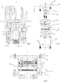
- a rotator arrangement 10 of a first embodiment of the invention is shown in a sectional view.
- the rotator arrangement 10 is arranged to provide a rotating movement and comprises a motor 11 with a rotor 12 and a stator 13, wherein the rotor 12 is arranged inside the stator 13 to rotate with respect to said stator 13 around an axial axis A.
- the rotator arrangement 10 comprises a rotor attachment piece 15 connected to the rotor 12 and a stator attachment piece 16 connected to the stator 13, wherein one of the rotor attachment piece 15 and stator attachment piece 16 is arranged to be attached to a crane arm or the like, and the other is arranged to be attached to a tool implement.
- stator attachment piece 16 is adapted to be arranged to a crane arm, typically a hydraulic pivot arm or the like.
- the rotor attachment piece 15 of the shown first embodiment is hence arranged to be attached to a tool implement, typically a hydraulically manoeuvrable tool implement such as a grip arm, bucket, harvesting tool or the like.
- An angle meter 17 is arranged to continuously monitor the rotation of the rotor 12 with respect to the stator 13.
- the angle meter is arranged as a module and comprises a stator part 18 that is arranged to rotate with the stator 13 a rotor part 19 that is arranged to rotate with the rotor 12.
- the stator part 18 of the angle meter 17 comprises a first connective portion 21 arranged to connect to the stator 13, and the rotor part 19 of the angle meter 17 comprises a second connective portion 22 arranged to connect to the rotor 12.
- the first connective portion 21 is comprised of a set of screw seats and screws arranged to be fastened in screw holes in the stator 13 of the motor 11.
- the angle meter 17 is arranged along the axial axis A around which the rotor 12 is arranged to rotate with respect to the stator 13.
- the rotor part 19 of the angle meter 17 is connected to a central portion of the rotor 12.
- the second connective portion 22 of the rotor part is adapted to the design of the rotor to which it is arranged to connect.
- the rotor 12 includes a recess 23 into which part of the second portion of the angle meter 17 may be received.
- the second connective portion 22 may be provided with a rubber detail arranged to interact with the inside of the recess 23 in the rotor so as to be urged to rotate with the rotor 12.
- a rotating body 31 of the rotor part 19 of the angle meter 17 is arranged to rotate with very low friction with respect to the stator part 18 of the angle meter 17.
- the angle meter 17 is arranged in a through hole 24 extending through the stator 13 to the rotor 12 such that the angle meter may be accessed from outside of the stator 13. Further, the angle meter 17 has a width that is smaller than the width of the through hole 24 through the stator 13. Thereby the angle meter 17 may be both accessed and removed or replaced from its position without needing to dismount the rotator arrangement.
- a conduct line 33 is arranged in the stator attachment for provision of electric lines to the angle meter 17.
- the stator part 18 of the angle meter 17 comprises a casing 25 arranged to protect the electronic devices inside the angle meter. Inside said casing a processor unit 26 is arranged, which may be programmable and include analogue/digital converter for converting an analogue signal from an sensor 27 to a digital signal. Further, the angle meter 17 comprises a sealing 28 and a holder 29. Additional sealings may be arranged to seal the space between the angle meter and the rotor and/or the stator.
- the rotor part 19 of the angle meter 17 comprises an angle indicator 30, typically in the shape of a magnet, arranged on a rotating body 31.
- the sensor 27 of the stator part 18 is arranged to sense the position of the angle indicator 30 and to, based on the sensed position, continuously monitor the angular position of the rotor 12 with respect to the stator 13.
- the angle indicator may have a cylindrical shape, a polygonal shape or it may be ring-shaped.
- the sensor 27 may as in the figures be arranged axially aligned to the angle indicator 30 or radially outside the angle indicator.
- An advantage of the inventive angle meter 17 is that it may be easily serviced and/or upgraded.
- the size of the casing 25 of the stator part 18 of the angle meter 17 is preferably adapted to house additional sensors or the like, such as e.g. a gyro, a GPS-transmitter, a temperature sensor etc.
- additional sensors or the like such as e.g. a gyro, a GPS-transmitter, a temperature sensor etc.
- the angle meter is arranged such that it may be readily accessible from outside of the rotator, and that the shape of the angle meter is adapted to house further sensible electronic devices.
- the rotating body 31 further comprises an electric swivel 32 providing an electric connection through the rotor 12 to the tool arranged to the rotor attachment piece 15 on the opposite side of the rotor.
- An electric connection 34 is provided in the innermost part of the angle meter 17, including electric cables and control lines for providing the tool with electric power and a signalling connection. The cables and lines are connected via electric cables (not shown) to the tool attached to the rotor attachment part 15.
- a rotator arrangement 10 according to a second embodiment is shown in figure 4 .
- the angle meter 17 does not include an electric swivel.
- the rotor 12 does not include a recess to receive a rotating part of the rotor part of the angle meter.
- the rotor part 19 of the angle meter is mainly comprised of a holder portion for holding the angle indicator 30 and a second connective portion 22 which is to be connected to a flat portion of the rotor 12.
- the rotor part 19 of the angle meter 17 may be comprised of merely an angle indicator 30, wherein the second connective portion 22 is comprised of an adhesive connecting the angle indicator 30 to the rotation of the rotor 12.
- Hydraulic conduits 38 are arranged through the rotor 12 for connection to the tool attached to the rotor attachment piece 15, via axial connections 39 or radial connections 40.
- a rotator arrangement 10 according to a third embodiment is shown.
- the rotor attachment piece 15 is arranged to be connected to a crane arm or the like, and the stator attachment piece 16 is arranged to be attached to a tool implement.
- the rotor attachment piece 15 is connected to the rotor 12 via an intermediate torque element for transmitting the torque therebetween.
- Axial forces are arranged to be handled by the stator without acting on the rotor 12. This is an advantage as it allows the angle meter to be arranged in a position where it is not exposed to any forces that may influence the angle metering.
- the rotor part 19 of the angle meter 17 is adapted to be attached to a rotor 12 with a central recess, without extending into said recess.
- the rotor part 19 of the angle meter 17 is provided with a radially extending portion with a second connective portion 22 in the form of screw holes for receiving screws that are to be screwed into the rotor 12.
- a rotating body is arranged as an integrated part of the rotor part 19 of the angle meter 17, or as part connected thereto, and is arranged to hold an angle indicator 30.
- the stator part 18 of the angle meter 17 is arranged to partially enclose the rotor part 19 with the sensor 27 arranged axially aligned to the angle indicator 30 with a small gap formed between the sensor 27 and the angle indicator 30.
- the motor 11 comprises a hollow rotor 12 arranged inside a stator 13.
- the rotor attachment part 15 is arranged to be attached to a crane arm, typically a hydraulic pivot arm or the like, and the stator attachment part 16 is arranged to be attached to a tool implement.
- Hydraulic conduits 46, electric cables and possibly conduits for urea are arranged to pass through the hollow rotor 12 to the rotor part 42 of a hydraulic swivel 41.
- a fluid conduit 45 for urea is arranged along the central axis A of the motor 11.
- the rotor part 19 of the angle meter 17 is arranged to rotate with the rotor 12, but only via an auxiliary device.
- an angle indicator 30, typically on the form of a magnet may be connected to an end portion of a fluid conduit 45 running centrally through the rotor along the axial axis A thereof and extending outside of the rotor 12.
- the fluid conduit 45 is part of a urea swivel 44.
- the angle indicator 30 may be provided in connection to the portion of the fluid conduit 45 that extends outside of the rotor 12, wherein the stator part 18 of the angle meter 17 is arranged with the sensor 27 arranged axially aligned to the angle indicator 30, or radially outside the angle indicator, with a small gap formed between the sensor 27 and the angle indicator 30.
- the stator part 18 may be arranged to partially enclose the rotor part 19 and the angle indicator.
- the rotator arrangement comprises a hydraulic swivel, an electric swivel 32, and a urea swivel 44 which are all arranged in the axial extension of the hydraulic motor 11.
- the fluid conduit 45 is arranged to pass through the centre of all of the three swivels.
- the urea swivel may be disposed with, such that the angle meter may be integrated with the electric swivel, the angle indicator being arranged on the rotor part of the electric swivel.
Landscapes
- Engineering & Computer Science (AREA)
- Mechanical Engineering (AREA)
- General Engineering & Computer Science (AREA)
- Mining & Mineral Resources (AREA)
- Civil Engineering (AREA)
- Structural Engineering (AREA)
- Automation & Control Theory (AREA)
- Measurement Of Length, Angles, Or The Like Using Electric Or Magnetic Means (AREA)
- Component Parts Of Construction Machinery (AREA)
Description
- The invention relates to a rotator arrangement for providing a rotating movement, the rotator arrangement comprising a motor with a stator and a rotor arranged inside the stator. Specifically, the invention relates to such a rotator arrangement with an angle meter.
- Rotator arrangements are widely used in foresting, harvesting or the like where a carrier, truck, tractor or the like carries an arrangement for handling excavators, timber tools, harvest tools or the like. Often such arrangements are hydraulically driven and include a crane arm, wherein the rotator arrangement is arranged to the free end of the arm. The rotator arrangement typically includes a motor, i.e. a hydraulic motor, to provide rotational movement.
- Such rotator arrangements are exposed to heavy forces both radially and axially. Conventionally, these heavy forces are handled by dimensioning the rotator arrangement and specifically the motor with components adapted to withstand very high efforts. In combination to this high mechanical demands the precision of the components, including the fit between the stator and rotor needs to be very accurate and precise. Further, to meet the demands of the users, rotator arrangements of today are provided with more and more precision demanding electronics, such as positioning devices and the like.
- A problem involved with the arrangement of sensitive apparels in the harsh environment of a rotator arrangement, is both to arrange them in a manner such that they are not exposed to high mechanical efforts and such that they may be accessed to be serviced, updated or exchanged when needed.
- Hence there is a need of an arrangement that facilitates installation of sensitive apparels such as an angle meter and that provides a reliable metering over time A rotator arrangement according to the preamble of claim 1 is known from
WO 2016/099372 A1 . - It is an object of the present invention to provide a rotator arrangement in which an angle meter is provided in a manner that facilitates installation thereof and that provides a possibility of service and/or upgrading of the angle meter.
- The invention relates to a rotator arrangement for providing a rotating movement, the rotator arrangement comprising a motor with a stator and a rotor arranged inside the stator to rotate with respect to said stator around an axial axis, wherein the rotator arrangement comprises a rotor attachment piece connected to the rotor and a stator attachment piece connected to the stator, wherein one of the rotor attachment piece and stator attachment piece is arranged to be attached to a crane arm or the like, and the other is arranged to be attached to a tool implement, wherein an angle meter is arranged to monitor the rotation of the rotor with respect to the stator, wherein the angle meter comprises a stator part that is connected to the stator and a rotor part that is arranged to rotate with the rotor, wherein the rotor part is arranged centrally along the axial axis.
- In a specific embodiment the rotor part and the stator part of the angle meter are arranged as separate parts at least partially inside the rotator arrangement, the sensor of the stator part being arranged with a gap with respect to the angle indicator of the rotor part.
- In a specific embodiment the stator part of the angle meter is arranged to extend into a through hole through the stator to the rotor.
- In a specific embodiment a part of the stator part of the angle meter that extend into the through hole through the stator has a width that is smaller than the width of said through hole, such that the stator part of the angle meter may be accessed from outside of the stator without dismounting the rotator arrangement.
- In a specific embodiment the angle meter is configured to provide an absolute angular position of the rotor with respect to the stator, the sensor being configured to monitor an absolute angular position of the angle indicator.
- In a specific embodiment the rotator arrangement comprises a swivel for urea including a urea conduit running centrally through the rotor along the axial axis thereof and extending outside of the rotor, the angle indicator being provided in connection to the portion of the urea conduit that extends outside of the rotor.
- In a specific embodiment the rotator arrangement comprises an electric swivel, the angle indicator being connected to a rotor part of said electric swivel.
- In a specific embodiment the rotator arrangement comprises a hydraulic swivel, the angle indicator being connected to a rotor part of said hydraulic swivel.
- In a specific embodiment the sensor is arranged axially aligned to the angle indicator along the axial axis.
- In another specific embodiment the sensor is arranged radially outside the angle indicator.
- Other embodiments and advantages will be apparent from the detailed description and the appended drawings.
- An exemplary embodiment related to the invention will now be described with reference to the appended drawings, of which;
- Fig. 1
- is a sectional view of a rotator arrangement according to a first embodiment of the invention,
- Fig. 2
- is a sectional view of an angle meter of the first embodiment of the invention,
- Fig. 3
- is an exploded view of an angle meter of the first embodiment of the invention,
- Fig. 4
- is a sectional view of a rotator arrangement according to a second embodiment of the invention,
- Fig. 5
- is a sectional view of an angle meter of the second embodiment of the invention,
- Fig. 6
- is an exploded view of an angle meter of the second embodiment of the invention,
- Fig. 7
- is a sectional view of a rotator arrangement according to a third embodiment of the invention,
- Fig. 8
- is a sectional view of an angle meter of the third embodiment of the invention,
- Fig. 9
- is an exploded view of an angle meter of the third embodiment of the invention,
- Fig. 10
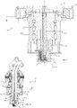
- is a sectional view of a rotator arrangement according to a fourth embodiment of the invention, and
- Fig. 11
- is a detailed view of the rotator arrangement in
fig. 10 . - In the figures below similar features of different embodiments of the inventive rotator arrangement have been given the same reference numerals even though there may be minor differences between the specific features of the different embodiments.
- In
Fig. 1 arotator arrangement 10 of a first embodiment of the invention is shown in a sectional view. Therotator arrangement 10 is arranged to provide a rotating movement and comprises amotor 11 with arotor 12 and astator 13, wherein therotor 12 is arranged inside thestator 13 to rotate with respect to saidstator 13 around an axial axis A. Therotator arrangement 10 comprises arotor attachment piece 15 connected to therotor 12 and astator attachment piece 16 connected to thestator 13, wherein one of therotor attachment piece 15 andstator attachment piece 16 is arranged to be attached to a crane arm or the like, and the other is arranged to be attached to a tool implement. In the shown first embodiment thestator attachment piece 16 is adapted to be arranged to a crane arm, typically a hydraulic pivot arm or the like. Therotor attachment piece 15 of the shown first embodiment is hence arranged to be attached to a tool implement, typically a hydraulically manoeuvrable tool implement such as a grip arm, bucket, harvesting tool or the like. - An
angle meter 17 is arranged to continuously monitor the rotation of therotor 12 with respect to thestator 13. The angle meter is arranged as a module and comprises astator part 18 that is arranged to rotate with the stator 13 arotor part 19 that is arranged to rotate with therotor 12. Thestator part 18 of theangle meter 17 comprises a firstconnective portion 21 arranged to connect to thestator 13, and therotor part 19 of theangle meter 17 comprises a secondconnective portion 22 arranged to connect to therotor 12. In the shown first embodiment the firstconnective portion 21 is comprised of a set of screw seats and screws arranged to be fastened in screw holes in thestator 13 of themotor 11. - The
angle meter 17 is arranged along the axial axis A around which therotor 12 is arranged to rotate with respect to thestator 13. Therotor part 19 of theangle meter 17 is connected to a central portion of therotor 12. Typically, the secondconnective portion 22 of the rotor part is adapted to the design of the rotor to which it is arranged to connect. In the shown first embodiment, therotor 12 includes arecess 23 into which part of the second portion of theangle meter 17 may be received. The secondconnective portion 22 may be provided with a rubber detail arranged to interact with the inside of therecess 23 in the rotor so as to be urged to rotate with therotor 12. It may also be connected to the rotation of therotor 12 via anelectric connection 34 to a cable providing the tool attached to the rotor attachment part with electricity. A rotatingbody 31 of therotor part 19 of theangle meter 17 is arranged to rotate with very low friction with respect to thestator part 18 of theangle meter 17. - The
angle meter 17 is arranged in a throughhole 24 extending through thestator 13 to therotor 12 such that the angle meter may be accessed from outside of thestator 13. Further, theangle meter 17 has a width that is smaller than the width of the throughhole 24 through thestator 13. Thereby theangle meter 17 may be both accessed and removed or replaced from its position without needing to dismount the rotator arrangement. - A
conduct line 33 is arranged in the stator attachment for provision of electric lines to theangle meter 17. - In
figure 2 and 3 theangle meter 17 in accordance with the first embodiment is shown in detailed in a sectional view and an exploded view, respectively. - The
stator part 18 of theangle meter 17 comprises acasing 25 arranged to protect the electronic devices inside the angle meter. Inside said casing aprocessor unit 26 is arranged, which may be programmable and include analogue/digital converter for converting an analogue signal from ansensor 27 to a digital signal. Further, theangle meter 17 comprises a sealing 28 and aholder 29. Additional sealings may be arranged to seal the space between the angle meter and the rotor and/or the stator. - The
rotor part 19 of theangle meter 17 comprises anangle indicator 30, typically in the shape of a magnet, arranged on arotating body 31. Thesensor 27 of thestator part 18 is arranged to sense the position of theangle indicator 30 and to, based on the sensed position, continuously monitor the angular position of therotor 12 with respect to thestator 13. The angle indicator may have a cylindrical shape, a polygonal shape or it may be ring-shaped. Thesensor 27 may as in the figures be arranged axially aligned to theangle indicator 30 or radially outside the angle indicator. - An advantage of the
inventive angle meter 17 is that it may be easily serviced and/or upgraded. The size of thecasing 25 of thestator part 18 of theangle meter 17 is preferably adapted to house additional sensors or the like, such as e.g. a gyro, a GPS-transmitter, a temperature sensor etc. In this respect it is advantageous both that the angle meter is arranged such that it may be readily accessible from outside of the rotator, and that the shape of the angle meter is adapted to house further sensible electronic devices. - In this specific first embodiment, the rotating
body 31 further comprises anelectric swivel 32 providing an electric connection through therotor 12 to the tool arranged to therotor attachment piece 15 on the opposite side of the rotor. Anelectric connection 34 is provided in the innermost part of theangle meter 17, including electric cables and control lines for providing the tool with electric power and a signalling connection. The cables and lines are connected via electric cables (not shown) to the tool attached to therotor attachment part 15. - A
rotator arrangement 10 according to a second embodiment is shown infigure 4 . A main difference of this embodiment with respect to the first embodiment shown infigures 1-3 is that theangle meter 17 does not include an electric swivel. Further, therotor 12 does not include a recess to receive a rotating part of the rotor part of the angle meter. Instead, therotor part 19 of the angle meter is mainly comprised of a holder portion for holding theangle indicator 30 and a secondconnective portion 22 which is to be connected to a flat portion of therotor 12. Therotor part 19 of theangle meter 17 may be comprised of merely anangle indicator 30, wherein the secondconnective portion 22 is comprised of an adhesive connecting theangle indicator 30 to the rotation of therotor 12. -
Hydraulic conduits 38 are arranged through therotor 12 for connection to the tool attached to therotor attachment piece 15, viaaxial connections 39 orradial connections 40. - In
figure 7 arotator arrangement 10 according to a third embodiment is shown. In this embodiment therotor attachment piece 15 is arranged to be connected to a crane arm or the like, and thestator attachment piece 16 is arranged to be attached to a tool implement. Therotor attachment piece 15 is connected to therotor 12 via an intermediate torque element for transmitting the torque therebetween. Axial forces are arranged to be handled by the stator without acting on therotor 12. This is an advantage as it allows the angle meter to be arranged in a position where it is not exposed to any forces that may influence the angle metering. - In this third embodiment the
rotor part 19 of theangle meter 17 is adapted to be attached to arotor 12 with a central recess, without extending into said recess. Instead, therotor part 19 of theangle meter 17 is provided with a radially extending portion with a secondconnective portion 22 in the form of screw holes for receiving screws that are to be screwed into therotor 12. A rotating body is arranged as an integrated part of therotor part 19 of theangle meter 17, or as part connected thereto, and is arranged to hold anangle indicator 30. - The
stator part 18 of theangle meter 17 is arranged to partially enclose therotor part 19 with thesensor 27 arranged axially aligned to theangle indicator 30 with a small gap formed between thesensor 27 and theangle indicator 30. - In
figures 10 and 11 a fourth embodiment of theinventive rotator arrangement 10 is shown. In this embodiment, themotor 11 comprises ahollow rotor 12 arranged inside astator 13. Therotor attachment part 15 is arranged to be attached to a crane arm, typically a hydraulic pivot arm or the like, and thestator attachment part 16 is arranged to be attached to a tool implement.Hydraulic conduits 46, electric cables and possibly conduits for urea are arranged to pass through thehollow rotor 12 to therotor part 42 of ahydraulic swivel 41. In the shown embodiment afluid conduit 45 for urea is arranged along the central axis A of themotor 11. - The
rotor part 19 of theangle meter 17 is arranged to rotate with therotor 12, but only via an auxiliary device. For example, anangle indicator 30, typically on the form of a magnet, may be connected to an end portion of afluid conduit 45 running centrally through the rotor along the axial axis A thereof and extending outside of therotor 12. In the shown embodiment thefluid conduit 45 is part of aurea swivel 44. Theangle indicator 30 may be provided in connection to the portion of thefluid conduit 45 that extends outside of therotor 12, wherein thestator part 18 of theangle meter 17 is arranged with thesensor 27 arranged axially aligned to theangle indicator 30, or radially outside the angle indicator, with a small gap formed between thesensor 27 and theangle indicator 30. Thestator part 18 may be arranged to partially enclose therotor part 19 and the angle indicator. - In the shown embodiment the rotator arrangement comprises a hydraulic swivel, an
electric swivel 32, and aurea swivel 44 which are all arranged in the axial extension of thehydraulic motor 11. Thefluid conduit 45 is arranged to pass through the centre of all of the three swivels. In another possible not shown embodiment of the inventive rotator arrangement the urea swivel may be disposed with, such that the angle meter may be integrated with the electric swivel, the angle indicator being arranged on the rotor part of the electric swivel. - Above, the invention has been described with reference to specific embodiments. The invention is however not limited to these embodiments. It is obvious to a person skilled in the art that other embodiments are possible within the scope of the following claims.
Claims (10)
- A rotator arrangement (10) for providing a rotating movement, the rotator arrangement comprising a motor (11) with a stator (13) and a rotor (12) arranged inside the stator (13) to rotate with respect to said stator (13) around an axial axis (A), wherein the rotator arrangement (10) comprises a rotor attachment piece (15) connected to the rotor and a stator attachment piece (16) connected to the stator, wherein one of the rotor attachment piece (15) and stator attachment piece (16) is arranged to be attached to a crane arm or the like, and the other is arranged to be attached to a tool implement, wherein an angle meter (17) is arranged to monitor the rotation of the rotor (12) with respect to the stator (13), wherein the angle meter (17) comprises a rotor part (19) with an angle indicator (30) that is arranged to rotate with the rotor (12), and a stator part (18) with a sensor (27) arranged to monitor the angular position of said angle indicator (30), which stator part (18) is connected to the stator (13), characterised in that the rotor part (19) is arranged centrally along the axial axis (A).
- A rotator arrangement (10) according to claim 1, wherein the rotor part (19) and the stator part (18) of the angle meter (17) are arranged as separate parts at least partially inside the rotator arrangement, the sensor (26) of the stator part (18) being arranged with a gap with respect to the angle indicator (30) of the rotor part (19).
- A rotator arrangement (10) according to claim 1 or 2, wherein the stator part (18) of the angle meter (17) is arranged to extend into a through hole (23) through the stator (13) to the rotor (12).
- A rotator arrangement (10) according to claim 3, wherein a part of the stator part (18) of the angle meter (17) that extend into the through hole (24) through the stator (13) has a width that is smaller than the width of said through hole (24), such that the stator part (18) of the angle meter (17) may be accessed from outside of the stator (13) without dismounting the rotator arrangement (10).
- A rotator arrangement (10) according to anyone of the preceding claims, wherein the angle meter (17) is configured to provide an absolute angular position of the rotor (12) with respect to the stator (13), the sensor (27) being configured to monitor an absolute angular position of the angle indicator (30).
- A rotator arrangement (10) according to anyone of the preceding claims, wherein the rotator arrangement (10) comprises a swivel (44) for urea including a urea conduit running centrally through the rotor along the axial axis (A) thereof and extending outside of the rotor (12), the angle indicator (30) being provided in connection to the portion of the urea conduit that extends outside of the rotor (12).
- A rotator arrangement (10) according to anyone of the claims 1-5, wherein the rotator arrangement (10) comprises an electric swivel (32), the angle indicator (30) being connected to a rotor part of said electric swivel.
- A rotator arrangement (10) according to anyone of the claims 1-5, wherein the rotator arrangement (10) comprises a hydraulic swivel (41), the angle indicator (30) being connected to a rotor part (42) of said hydraulic swivel (41).
- A rotator arrangement (10) according to anyone of the preceding claims, wherein the sensor (27) is arranged axially aligned to the angle indicator (30) along the axial axis (A).
- A rotator arrangement (10) according to anyone of the preceding claims, wherein the sensor (27) is arranged radially outside the angle indicator (30).
Applications Claiming Priority (2)
| Application Number | Priority Date | Filing Date | Title |
|---|---|---|---|
| SE1750246A SE541661C2 (en) | 2017-03-06 | 2017-03-06 | Rotator arrangement with an angle meter |
| PCT/EP2018/055371 WO2018162424A1 (en) | 2017-03-06 | 2018-03-05 | Rotator arrangement with an angle meter |
Publications (2)
| Publication Number | Publication Date |
|---|---|
| EP3592685A1 EP3592685A1 (en) | 2020-01-15 |
| EP3592685B1 true EP3592685B1 (en) | 2021-04-28 |
Family
ID=61683755
Family Applications (1)
| Application Number | Title | Priority Date | Filing Date |
|---|---|---|---|
| EP18711501.9A Active EP3592685B1 (en) | 2017-03-06 | 2018-03-05 | Rotator arrangement with an angle meter |
Country Status (6)
| Country | Link |
|---|---|
| US (1) | US10808380B2 (en) |
| EP (1) | EP3592685B1 (en) |
| BR (1) | BR112019018436B1 (en) |
| RU (1) | RU2746741C2 (en) |
| SE (1) | SE541661C2 (en) |
| WO (1) | WO2018162424A1 (en) |
Cited By (1)
| Publication number | Priority date | Publication date | Assignee | Title |
|---|---|---|---|---|
| WO2025106003A1 (en) * | 2023-11-14 | 2025-05-22 | Indexator Rotator Systems Ab | Rotator for a hydraulic tool |
Families Citing this family (8)
| Publication number | Priority date | Publication date | Assignee | Title |
|---|---|---|---|---|
| SI3388385T1 (en) | 2017-04-12 | 2022-01-31 | Epsilon Kran Gmbh | Rotation drive |
| EP3863955A4 (en) * | 2018-10-12 | 2022-07-06 | Indexator Rotator Systems AB | SYSTEM FOR CONTROLLING A ROTATOR BY IMAGE DETECTION MEANS |
| US11035947B2 (en) * | 2018-11-06 | 2021-06-15 | Aerial Surveying, Inc | Radio frequency (RF) ranging in propagation limited RF environments |
| WO2021206608A1 (en) * | 2020-04-08 | 2021-10-14 | Indexator Rotator Systems Ab | Rotator for a tool |
| BR112023000011A2 (en) * | 2020-07-03 | 2023-01-31 | Indexator Rotator Sys Ab | ROTATOR FOR A TOOL |
| US12195306B2 (en) | 2021-04-12 | 2025-01-14 | Structural Services, Inc. | Systems and methods for identifying and locating building material objects |
| KR20240007160A (en) | 2021-04-12 | 2024-01-16 | 스트럭처럴 서비시스, 인크. | Systems and methods for supporting crane operators |
| SE546732C2 (en) * | 2021-12-17 | 2025-02-11 | Sjoelander Garage & Eng Ab | Rotator |
Family Cites Families (3)
| Publication number | Priority date | Publication date | Assignee | Title |
|---|---|---|---|---|
| SE524754C2 (en) * | 2002-01-21 | 2004-09-28 | Indexator Ab | Rotator with rotary position sensor and method for rotary position determination in a rotator |
| ATE442339T1 (en) * | 2006-04-03 | 2009-09-15 | Epsilon Kran Gmbh | CRANE ARM WITH A FASTENING DEVICE FOR WORK EQUIPMENT |
| SE538568C2 (en) | 2014-12-19 | 2016-09-20 | Indexator Rotator Sys Ab | Rotator for a jib-carried tool |
-
2017
- 2017-03-06 SE SE1750246A patent/SE541661C2/en unknown
-
2018
- 2018-03-05 RU RU2019131367A patent/RU2746741C2/en active
- 2018-03-05 US US16/486,199 patent/US10808380B2/en active Active
- 2018-03-05 WO PCT/EP2018/055371 patent/WO2018162424A1/en not_active Ceased
- 2018-03-05 BR BR112019018436-8A patent/BR112019018436B1/en active IP Right Grant
- 2018-03-05 EP EP18711501.9A patent/EP3592685B1/en active Active
Non-Patent Citations (1)
| Title |
|---|
| None * |
Cited By (1)
| Publication number | Priority date | Publication date | Assignee | Title |
|---|---|---|---|---|
| WO2025106003A1 (en) * | 2023-11-14 | 2025-05-22 | Indexator Rotator Systems Ab | Rotator for a hydraulic tool |
Also Published As
| Publication number | Publication date |
|---|---|
| EP3592685A1 (en) | 2020-01-15 |
| BR112019018436A2 (en) | 2020-04-14 |
| US20200002917A1 (en) | 2020-01-02 |
| BR112019018436B1 (en) | 2023-05-16 |
| RU2019131367A3 (en) | 2021-04-07 |
| US10808380B2 (en) | 2020-10-20 |
| RU2746741C2 (en) | 2021-04-20 |
| WO2018162424A1 (en) | 2018-09-13 |
| CA3049832A1 (en) | 2018-09-13 |
| RU2019131367A (en) | 2021-04-07 |
| SE1750246A1 (en) | 2018-09-07 |
| SE541661C2 (en) | 2019-11-19 |
Similar Documents
| Publication | Publication Date | Title |
|---|---|---|
| US10808380B2 (en) | Rotator arrangement with an angle meter | |
| US7836782B2 (en) | Motor pump torque transducer | |
| EP3462138A1 (en) | Board mounted microelectromechanic system (mems) sensors for motor diagnostics and analytics | |
| US20240360929A1 (en) | Rotating joint | |
| CA3049832C (en) | Rotator arrangement with an angle meter | |
| US4947690A (en) | Acceletometers adapted for efficient connection and disconnection | |
| EP4175906B1 (en) | Rotator for a tool | |
| US11883918B2 (en) | Measuring system for monitoring a spindle | |
| CN108279083B (en) | Rotary shaft joint structure | |
| RU2709232C2 (en) | Rotation drive | |
| US12442154B2 (en) | Rotator for a tool | |
| US7460010B2 (en) | System for detecting the rotational motion of a shaft | |
| RU2822595C2 (en) | Sensor of torque and angular speed for drive shafts | |
| EP0216040A2 (en) | Torque sensor | |
| CN105157902A (en) | Cable tension sensor | |
| US20250119028A1 (en) | Tachometer assembly for a motor-mounted brake, motor-mounted brake and drive assembly | |
| CN223597203U (en) | A testing device for magnetic couplings | |
| CN113965023B (en) | Motor torque and rotation speed on-line monitoring device and motor | |
| EP4388213A1 (en) | Torque and angular velocity sensor for driveshafts | |
| WO2023027662A1 (en) | Torque and angular velocity sensor for driveshafts | |
| WO2025106003A1 (en) | Rotator for a hydraulic tool | |
| RU164862U1 (en) | DEVICE FOR DETERMINING ANGLE OF TURNING THE PLATFORM OF THE LIFTING AND TRANSPORT MACHINE | |
| WO2018038677A1 (en) | Rotator arrangement | |
| RU161463U1 (en) | DEVICE FOR DETERMINING ANGLE OF TURNING THE PLATFORM OF THE LIFTING AND TRANSPORT MACHINE | |
| CN115720623A (en) | Housing for a rotating component |
Legal Events
| Date | Code | Title | Description |
|---|---|---|---|
| STAA | Information on the status of an ep patent application or granted ep patent |
Free format text: STATUS: UNKNOWN |
|
| STAA | Information on the status of an ep patent application or granted ep patent |
Free format text: STATUS: THE INTERNATIONAL PUBLICATION HAS BEEN MADE |
|
| PUAI | Public reference made under article 153(3) epc to a published international application that has entered the european phase |
Free format text: ORIGINAL CODE: 0009012 |
|
| STAA | Information on the status of an ep patent application or granted ep patent |
Free format text: STATUS: REQUEST FOR EXAMINATION WAS MADE |
|
| 17P | Request for examination filed |
Effective date: 20190819 |
|
| AK | Designated contracting states |
Kind code of ref document: A1 Designated state(s): AL AT BE BG CH CY CZ DE DK EE ES FI FR GB GR HR HU IE IS IT LI LT LU LV MC MK MT NL NO PL PT RO RS SE SI SK SM TR |
|
| AX | Request for extension of the european patent |
Extension state: BA ME |
|
| DAV | Request for validation of the european patent (deleted) | ||
| DAX | Request for extension of the european patent (deleted) | ||
| GRAP | Despatch of communication of intention to grant a patent |
Free format text: ORIGINAL CODE: EPIDOSNIGR1 |
|
| STAA | Information on the status of an ep patent application or granted ep patent |
Free format text: STATUS: GRANT OF PATENT IS INTENDED |
|
| INTG | Intention to grant announced |
Effective date: 20210114 |
|
| GRAS | Grant fee paid |
Free format text: ORIGINAL CODE: EPIDOSNIGR3 |
|
| GRAA | (expected) grant |
Free format text: ORIGINAL CODE: 0009210 |
|
| STAA | Information on the status of an ep patent application or granted ep patent |
Free format text: STATUS: THE PATENT HAS BEEN GRANTED |
|
| AK | Designated contracting states |
Kind code of ref document: B1 Designated state(s): AL AT BE BG CH CY CZ DE DK EE ES FI FR GB GR HR HU IE IS IT LI LT LU LV MC MK MT NL NO PL PT RO RS SE SI SK SM TR |
|
| REG | Reference to a national code |
Ref country code: GB Ref legal event code: FG4D |
|
| REG | Reference to a national code |
Ref country code: CH Ref legal event code: EP |
|
| REG | Reference to a national code |
Ref country code: DE Ref legal event code: R096 Ref document number: 602018016208 Country of ref document: DE |
|
| REG | Reference to a national code |
Ref country code: AT Ref legal event code: REF Ref document number: 1386863 Country of ref document: AT Kind code of ref document: T Effective date: 20210515 |
|
| REG | Reference to a national code |
Ref country code: IE Ref legal event code: FG4D |
|
| REG | Reference to a national code |
Ref country code: FI Ref legal event code: FGE |
|
| REG | Reference to a national code |
Ref country code: SE Ref legal event code: TRGR |
|
| REG | Reference to a national code |
Ref country code: LT Ref legal event code: MG9D |
|
| PG25 | Lapsed in a contracting state [announced via postgrant information from national office to epo] |
Ref country code: NL Free format text: LAPSE BECAUSE OF FAILURE TO SUBMIT A TRANSLATION OF THE DESCRIPTION OR TO PAY THE FEE WITHIN THE PRESCRIBED TIME-LIMIT Effective date: 20210428 Ref country code: BG Free format text: LAPSE BECAUSE OF FAILURE TO SUBMIT A TRANSLATION OF THE DESCRIPTION OR TO PAY THE FEE WITHIN THE PRESCRIBED TIME-LIMIT Effective date: 20210728 Ref country code: HR Free format text: LAPSE BECAUSE OF FAILURE TO SUBMIT A TRANSLATION OF THE DESCRIPTION OR TO PAY THE FEE WITHIN THE PRESCRIBED TIME-LIMIT Effective date: 20210428 Ref country code: LT Free format text: LAPSE BECAUSE OF FAILURE TO SUBMIT A TRANSLATION OF THE DESCRIPTION OR TO PAY THE FEE WITHIN THE PRESCRIBED TIME-LIMIT Effective date: 20210428 |
|
| PG25 | Lapsed in a contracting state [announced via postgrant information from national office to epo] |
Ref country code: IS Free format text: LAPSE BECAUSE OF FAILURE TO SUBMIT A TRANSLATION OF THE DESCRIPTION OR TO PAY THE FEE WITHIN THE PRESCRIBED TIME-LIMIT Effective date: 20210828 Ref country code: GR Free format text: LAPSE BECAUSE OF FAILURE TO SUBMIT A TRANSLATION OF THE DESCRIPTION OR TO PAY THE FEE WITHIN THE PRESCRIBED TIME-LIMIT Effective date: 20210729 Ref country code: PL Free format text: LAPSE BECAUSE OF FAILURE TO SUBMIT A TRANSLATION OF THE DESCRIPTION OR TO PAY THE FEE WITHIN THE PRESCRIBED TIME-LIMIT Effective date: 20210428 Ref country code: NO Free format text: LAPSE BECAUSE OF FAILURE TO SUBMIT A TRANSLATION OF THE DESCRIPTION OR TO PAY THE FEE WITHIN THE PRESCRIBED TIME-LIMIT Effective date: 20210728 Ref country code: RS Free format text: LAPSE BECAUSE OF FAILURE TO SUBMIT A TRANSLATION OF THE DESCRIPTION OR TO PAY THE FEE WITHIN THE PRESCRIBED TIME-LIMIT Effective date: 20210428 Ref country code: PT Free format text: LAPSE BECAUSE OF FAILURE TO SUBMIT A TRANSLATION OF THE DESCRIPTION OR TO PAY THE FEE WITHIN THE PRESCRIBED TIME-LIMIT Effective date: 20210830 |
|
| REG | Reference to a national code |
Ref country code: AT Ref legal event code: UEP Ref document number: 1386863 Country of ref document: AT Kind code of ref document: T Effective date: 20210428 |
|
| REG | Reference to a national code |
Ref country code: NL Ref legal event code: MP Effective date: 20210428 |
|
| PG25 | Lapsed in a contracting state [announced via postgrant information from national office to epo] |
Ref country code: ES Free format text: LAPSE BECAUSE OF FAILURE TO SUBMIT A TRANSLATION OF THE DESCRIPTION OR TO PAY THE FEE WITHIN THE PRESCRIBED TIME-LIMIT Effective date: 20210428 Ref country code: EE Free format text: LAPSE BECAUSE OF FAILURE TO SUBMIT A TRANSLATION OF THE DESCRIPTION OR TO PAY THE FEE WITHIN THE PRESCRIBED TIME-LIMIT Effective date: 20210428 Ref country code: SM Free format text: LAPSE BECAUSE OF FAILURE TO SUBMIT A TRANSLATION OF THE DESCRIPTION OR TO PAY THE FEE WITHIN THE PRESCRIBED TIME-LIMIT Effective date: 20210428 Ref country code: SK Free format text: LAPSE BECAUSE OF FAILURE TO SUBMIT A TRANSLATION OF THE DESCRIPTION OR TO PAY THE FEE WITHIN THE PRESCRIBED TIME-LIMIT Effective date: 20210428 Ref country code: RO Free format text: LAPSE BECAUSE OF FAILURE TO SUBMIT A TRANSLATION OF THE DESCRIPTION OR TO PAY THE FEE WITHIN THE PRESCRIBED TIME-LIMIT Effective date: 20210428 Ref country code: CZ Free format text: LAPSE BECAUSE OF FAILURE TO SUBMIT A TRANSLATION OF THE DESCRIPTION OR TO PAY THE FEE WITHIN THE PRESCRIBED TIME-LIMIT Effective date: 20210428 Ref country code: DK Free format text: LAPSE BECAUSE OF FAILURE TO SUBMIT A TRANSLATION OF THE DESCRIPTION OR TO PAY THE FEE WITHIN THE PRESCRIBED TIME-LIMIT Effective date: 20210428 |
|
| REG | Reference to a national code |
Ref country code: DE Ref legal event code: R097 Ref document number: 602018016208 Country of ref document: DE |
|
| PLBE | No opposition filed within time limit |
Free format text: ORIGINAL CODE: 0009261 |
|
| STAA | Information on the status of an ep patent application or granted ep patent |
Free format text: STATUS: NO OPPOSITION FILED WITHIN TIME LIMIT |
|
| 26N | No opposition filed |
Effective date: 20220131 |
|
| PG25 | Lapsed in a contracting state [announced via postgrant information from national office to epo] |
Ref country code: IS Free format text: LAPSE BECAUSE OF FAILURE TO SUBMIT A TRANSLATION OF THE DESCRIPTION OR TO PAY THE FEE WITHIN THE PRESCRIBED TIME-LIMIT Effective date: 20210828 Ref country code: AL Free format text: LAPSE BECAUSE OF FAILURE TO SUBMIT A TRANSLATION OF THE DESCRIPTION OR TO PAY THE FEE WITHIN THE PRESCRIBED TIME-LIMIT Effective date: 20210428 |
|
| PG25 | Lapsed in a contracting state [announced via postgrant information from national office to epo] |
Ref country code: IT Free format text: LAPSE BECAUSE OF FAILURE TO SUBMIT A TRANSLATION OF THE DESCRIPTION OR TO PAY THE FEE WITHIN THE PRESCRIBED TIME-LIMIT Effective date: 20210428 |
|
| PG25 | Lapsed in a contracting state [announced via postgrant information from national office to epo] |
Ref country code: MC Free format text: LAPSE BECAUSE OF FAILURE TO SUBMIT A TRANSLATION OF THE DESCRIPTION OR TO PAY THE FEE WITHIN THE PRESCRIBED TIME-LIMIT Effective date: 20210428 |
|
| REG | Reference to a national code |
Ref country code: CH Ref legal event code: PL |
|
| GBPC | Gb: european patent ceased through non-payment of renewal fee |
Effective date: 20220305 |
|
| REG | Reference to a national code |
Ref country code: BE Ref legal event code: MM Effective date: 20220331 |
|
| PG25 | Lapsed in a contracting state [announced via postgrant information from national office to epo] |
Ref country code: LU Free format text: LAPSE BECAUSE OF NON-PAYMENT OF DUE FEES Effective date: 20220305 Ref country code: LI Free format text: LAPSE BECAUSE OF NON-PAYMENT OF DUE FEES Effective date: 20220331 Ref country code: IE Free format text: LAPSE BECAUSE OF NON-PAYMENT OF DUE FEES Effective date: 20220305 Ref country code: GB Free format text: LAPSE BECAUSE OF NON-PAYMENT OF DUE FEES Effective date: 20220305 Ref country code: FR Free format text: LAPSE BECAUSE OF NON-PAYMENT OF DUE FEES Effective date: 20220331 Ref country code: CH Free format text: LAPSE BECAUSE OF NON-PAYMENT OF DUE FEES Effective date: 20220331 |
|
| PG25 | Lapsed in a contracting state [announced via postgrant information from national office to epo] |
Ref country code: BE Free format text: LAPSE BECAUSE OF NON-PAYMENT OF DUE FEES Effective date: 20220331 |
|
| P01 | Opt-out of the competence of the unified patent court (upc) registered |
Effective date: 20231118 |
|
| PG25 | Lapsed in a contracting state [announced via postgrant information from national office to epo] |
Ref country code: MK Free format text: LAPSE BECAUSE OF FAILURE TO SUBMIT A TRANSLATION OF THE DESCRIPTION OR TO PAY THE FEE WITHIN THE PRESCRIBED TIME-LIMIT Effective date: 20210428 Ref country code: CY Free format text: LAPSE BECAUSE OF FAILURE TO SUBMIT A TRANSLATION OF THE DESCRIPTION OR TO PAY THE FEE WITHIN THE PRESCRIBED TIME-LIMIT Effective date: 20210428 |
|
| PG25 | Lapsed in a contracting state [announced via postgrant information from national office to epo] |
Ref country code: HU Free format text: LAPSE BECAUSE OF FAILURE TO SUBMIT A TRANSLATION OF THE DESCRIPTION OR TO PAY THE FEE WITHIN THE PRESCRIBED TIME-LIMIT; INVALID AB INITIO Effective date: 20180305 |
|
| PG25 | Lapsed in a contracting state [announced via postgrant information from national office to epo] |
Ref country code: TR Free format text: LAPSE BECAUSE OF FAILURE TO SUBMIT A TRANSLATION OF THE DESCRIPTION OR TO PAY THE FEE WITHIN THE PRESCRIBED TIME-LIMIT Effective date: 20210428 |
|
| PG25 | Lapsed in a contracting state [announced via postgrant information from national office to epo] |
Ref country code: MT Free format text: LAPSE BECAUSE OF FAILURE TO SUBMIT A TRANSLATION OF THE DESCRIPTION OR TO PAY THE FEE WITHIN THE PRESCRIBED TIME-LIMIT Effective date: 20210428 |
|
| PGFP | Annual fee paid to national office [announced via postgrant information from national office to epo] |
Ref country code: SE Payment date: 20260320 Year of fee payment: 9 |
|
| PGFP | Annual fee paid to national office [announced via postgrant information from national office to epo] |
Ref country code: DE Payment date: 20260318 Year of fee payment: 9 |
|
| PGFP | Annual fee paid to national office [announced via postgrant information from national office to epo] |
Ref country code: AT Payment date: 20260318 Year of fee payment: 9 |
|
| PGFP | Annual fee paid to national office [announced via postgrant information from national office to epo] |
Ref country code: FI Payment date: 20260319 Year of fee payment: 9 |
|
| PGFP | Annual fee paid to national office [announced via postgrant information from national office to epo] |
Ref country code: LV Payment date: 20260318 Year of fee payment: 9 |