EP3592560B1 - 3d printing nozzle calibration inside a heated chamber - Google Patents
3d printing nozzle calibration inside a heated chamber Download PDFInfo
- Publication number
- EP3592560B1 EP3592560B1 EP18764938.9A EP18764938A EP3592560B1 EP 3592560 B1 EP3592560 B1 EP 3592560B1 EP 18764938 A EP18764938 A EP 18764938A EP 3592560 B1 EP3592560 B1 EP 3592560B1
- Authority
- EP
- European Patent Office
- Prior art keywords
- printing
- base plate
- nozzle
- printing nozzle
- hard stop
- Prior art date
- Legal status (The legal status is an assumption and is not a legal conclusion. Google has not performed a legal analysis and makes no representation as to the accuracy of the status listed.)
- Active
Links
Images



Classifications
-
- B—PERFORMING OPERATIONS; TRANSPORTING
- B29—WORKING OF PLASTICS; WORKING OF SUBSTANCES IN A PLASTIC STATE IN GENERAL
- B29C—SHAPING OR JOINING OF PLASTICS; SHAPING OF MATERIAL IN A PLASTIC STATE, NOT OTHERWISE PROVIDED FOR; AFTER-TREATMENT OF THE SHAPED PRODUCTS, e.g. REPAIRING
- B29C64/00—Additive manufacturing, i.e. manufacturing of three-dimensional [3D] objects by additive deposition, additive agglomeration or additive layering, e.g. by 3D printing, stereolithography or selective laser sintering
- B29C64/30—Auxiliary operations or equipment
- B29C64/386—Data acquisition or data processing for additive manufacturing
- B29C64/393—Data acquisition or data processing for additive manufacturing for controlling or regulating additive manufacturing processes
-
- B—PERFORMING OPERATIONS; TRANSPORTING
- B29—WORKING OF PLASTICS; WORKING OF SUBSTANCES IN A PLASTIC STATE IN GENERAL
- B29C—SHAPING OR JOINING OF PLASTICS; SHAPING OF MATERIAL IN A PLASTIC STATE, NOT OTHERWISE PROVIDED FOR; AFTER-TREATMENT OF THE SHAPED PRODUCTS, e.g. REPAIRING
- B29C64/00—Additive manufacturing, i.e. manufacturing of three-dimensional [3D] objects by additive deposition, additive agglomeration or additive layering, e.g. by 3D printing, stereolithography or selective laser sintering
- B29C64/20—Apparatus for additive manufacturing; Details thereof or accessories therefor
- B29C64/205—Means for applying layers
- B29C64/209—Heads; Nozzles
-
- B—PERFORMING OPERATIONS; TRANSPORTING
- B29—WORKING OF PLASTICS; WORKING OF SUBSTANCES IN A PLASTIC STATE IN GENERAL
- B29C—SHAPING OR JOINING OF PLASTICS; SHAPING OF MATERIAL IN A PLASTIC STATE, NOT OTHERWISE PROVIDED FOR; AFTER-TREATMENT OF THE SHAPED PRODUCTS, e.g. REPAIRING
- B29C64/00—Additive manufacturing, i.e. manufacturing of three-dimensional [3D] objects by additive deposition, additive agglomeration or additive layering, e.g. by 3D printing, stereolithography or selective laser sintering
- B29C64/20—Apparatus for additive manufacturing; Details thereof or accessories therefor
- B29C64/227—Driving means
-
- B—PERFORMING OPERATIONS; TRANSPORTING
- B29—WORKING OF PLASTICS; WORKING OF SUBSTANCES IN A PLASTIC STATE IN GENERAL
- B29C—SHAPING OR JOINING OF PLASTICS; SHAPING OF MATERIAL IN A PLASTIC STATE, NOT OTHERWISE PROVIDED FOR; AFTER-TREATMENT OF THE SHAPED PRODUCTS, e.g. REPAIRING
- B29C64/00—Additive manufacturing, i.e. manufacturing of three-dimensional [3D] objects by additive deposition, additive agglomeration or additive layering, e.g. by 3D printing, stereolithography or selective laser sintering
- B29C64/20—Apparatus for additive manufacturing; Details thereof or accessories therefor
- B29C64/227—Driving means
- B29C64/232—Driving means for motion along the axis orthogonal to the plane of a layer
-
- B—PERFORMING OPERATIONS; TRANSPORTING
- B29—WORKING OF PLASTICS; WORKING OF SUBSTANCES IN A PLASTIC STATE IN GENERAL
- B29C—SHAPING OR JOINING OF PLASTICS; SHAPING OF MATERIAL IN A PLASTIC STATE, NOT OTHERWISE PROVIDED FOR; AFTER-TREATMENT OF THE SHAPED PRODUCTS, e.g. REPAIRING
- B29C64/00—Additive manufacturing, i.e. manufacturing of three-dimensional [3D] objects by additive deposition, additive agglomeration or additive layering, e.g. by 3D printing, stereolithography or selective laser sintering
- B29C64/20—Apparatus for additive manufacturing; Details thereof or accessories therefor
- B29C64/245—Platforms or substrates
-
- B—PERFORMING OPERATIONS; TRANSPORTING
- B33—ADDITIVE MANUFACTURING TECHNOLOGY
- B33Y—ADDITIVE MANUFACTURING, i.e. MANUFACTURING OF THREE-DIMENSIONAL [3D] OBJECTS BY ADDITIVE DEPOSITION, ADDITIVE AGGLOMERATION OR ADDITIVE LAYERING, e.g. BY 3D PRINTING, STEREOLITHOGRAPHY OR SELECTIVE LASER SINTERING
- B33Y30/00—Apparatus for additive manufacturing; Details thereof or accessories therefor
-
- B—PERFORMING OPERATIONS; TRANSPORTING
- B33—ADDITIVE MANUFACTURING TECHNOLOGY
- B33Y—ADDITIVE MANUFACTURING, i.e. MANUFACTURING OF THREE-DIMENSIONAL [3D] OBJECTS BY ADDITIVE DEPOSITION, ADDITIVE AGGLOMERATION OR ADDITIVE LAYERING, e.g. BY 3D PRINTING, STEREOLITHOGRAPHY OR SELECTIVE LASER SINTERING
- B33Y50/00—Data acquisition or data processing for additive manufacturing
- B33Y50/02—Data acquisition or data processing for additive manufacturing for controlling or regulating additive manufacturing processes
-
- C—CHEMISTRY; METALLURGY
- C03—GLASS; MINERAL OR SLAG WOOL
- C03B—MANUFACTURE, SHAPING, OR SUPPLEMENTARY PROCESSES
- C03B19/00—Other methods of shaping glass
- C03B19/02—Other methods of shaping glass by casting molten glass, e.g. injection moulding
Definitions
- the present invention generally relates to printing systems and specifically to a 3D printing nozzle calibration system.
- 3D printing or Additive Manufacturing (AM), Fuse Depositing Modeling (FDM) and Fused Filament Fabrication (FFT) refer to any of the various processes for printing a three-dimensional object. Primarily additive processes are used, in which successive layers of material are laid down under computer control. These objects can be of almostany shape or geometry, and are produced from a 3D model or other electronic data source. Different types of 3D printers were developed over the years, such as 3D FDM(Fused Deposition Modeling) extrusion printers. 3D FDM extrusion printers are mostly based on melting a filament, e.g. plastics, in a printer head.
- the printing process has to be performed in a hot environment e.g., inside a heated chamber/furnace.
- the printing base plate is not perfectly flat so it is important to calibrate the nozzle height relative to the printing base plate in a number of points of the printing base plate area.
- the Height calibration is much more critical while printing at high temperatures because of the significant thermal expansion.
- US 2016/0271871 A1 discloses a 3D printer with a printing nozzle and a calibration module. While moving the printing base plate on XY plane to a number of determined points, the base plate moves up and down on Z axis until the distance sensor recognize the printing base plate. Performing this process in a number of determined points enables the printer controller to generate a mapping file of the nozzle's height relative to the printing base plate for the whole printing base plate area.
- the distance between the nozzle and the printing base plate (not the distance between the distance sensor and the printing base plate)
- another measurement is required, the distance between the nozzle and the printing base plate at least at one of the determined points. This measurement may be done manually by moving the nozzle towards the printing base plate. By using this method, there is a risk of damaging the nozzle by crashing it into the printing base plate.
- the heated chamber/furnace raises a problem of how to calibrate the nozzle's height while the nozzle's tip is mounted in a very hot environment (e.g., 600 deg C) inside the heated chamber/furnace where it is impossible to use standard electronic devices/distance sensors, etc.
- a very hot environment e.g. 600 deg C
- a 3D printing nozzle calibration system comprising: a heated chamber; a printing base plate mounted inside said heated chamber; printing base moving means configured to move said printing base plate; a moving carriage; at least one rail on which said moving carriage is configured to slide up and down; a printing nozzle partially mounted inside said heated chamber; said printing nozzle is connected to said moving carriage; a hard stop connected to said moving carriage; a fixed part on which said hard stop is resting; and a printer controller; wherein said printing base plate is configured to move up, up to a point where said printing base plate touches said printing nozzle in a determined point of said printing base plate, thereby causing said hard stop to disconnect from said fixed part; and wherein said printer controller is configured to store a height of said printing base plate upon said disconnection.
- a 3D printing nozzle calibration system comprising: a heated chamber; a printing base plate mounted inside said heated chamber; a moving carriage; a board comprising at least one rail on which said moving carriage is configured to slide up and down; a printing nozzle partially mounted inside said heated chamber; said printing nozzle is connected to said moving carriage; a hard stop connected to said moving carriage; a resting part connected to said board, on which said hard stop is resting; printing nozzle moving means configured to move said board, said printing nozzle, said carriage, said hard stop and said resting part; and a printer controller; wherein said printing nozzle is configured to move down along with said carriage, said hard stop and said resting part above a determined point of said printing base plate, up to a point where said printing base plate touches said printing nozzle, thereby causing said hard stop to disconnect from said resting part; and wherein said printer controller is configured to store a height of said printing nozzle upon said disconnection.
- a process for the calibration of a 3D printing nozzle in a 3D printing nozzle calibration system comprising: a printer controller; a heated chamber; a printing base plate mounted inside the heated chamber; printing base moving means configured to move the printing base plate in x, y and z planes; a moving carriage and at least one rail on which said moving carriage is configured to slide up and down along a z axis; a printing nozzle partially mounted inside the heated chamber and connected to said moving carriage and displaced from the printing base plate along the z axis, a hard stop also connected to said moving carriage and movable with said printing nozzle along the z axis; and a fixed stop on which the hard stop rests when the printing nozzle is in its printing position; the process comprising: (i) moving the printing base plate upwards towards the printing nozzle towards each other along the z axis until said printing base plate touches said printing nozzle and thereby causing said hard
- a process for the calibration of a 3D printing nozzle in a 3D printing nozzle calibration system comprising: a printer controller; a heated chamber; a printing base plate mounted inside the heated chamber; a moving carriage; a board comprising at least one rail on which the moving carriage is configured to slide up and down along a z axis; a printing nozzle partially mounted inside the heated chamber and connected to said moving carriage and displaced from the printing base plate along the z axis, a hard stop also connected to said moving carriage; and a resting part connected to the board on which the hard stop rests when the printing nozzle is in its printing position; and printing nozzle moving means configured to move the board, the printing nozzle, the carriage, the hard stop and said resting part; the process comprising: (i) moving said board, said moving carriage, said printing nozzle, said hard stop and said resting part down along the z axis until said printing nozzle touches said printing base plate and thereby causing said hard stop to
- the present invention provides a system for calibrating a 3D printing nozzle while the nozzle's tip is mounted in a hot (or very hot) environment (e.g., 600 deg C).
- a hot (or very hot) environment e.g. 600 deg C.
- 3D printing materials printed inside a heated chamber such as, glass, metal or any other printing material requiring high melting temperature may be referred to as printing material(s).
- the calibration process of the present invention is performed in a system printing using a fixed printing head/nozzle and a moving printing base plate, but this process may also be performed similarly in a system printing using a moving printing head/nozzle and a fixed printing base plate or any other combination of a moving printing nozzle and a moving printing base plate.
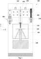
- Fig. 1 is a schematic view of a 3D printing nozzle calibration system 100, printing using a fixed printing head/nozzle and a moving printing base plate, according to embodiments of the present invention, comprising: a heated chamber/furnace 105, a printing head (nozzle) 110 partially mounted inside the heated chamber 105, a moving substrate/printing base plate 120 mounted inside the heated chamber 105, moving means 106 for moving the printing base plate 120 in the XYZ planes, a moving carriage 140 to which the printing nozzle 110 is connected, at least one linear guide rail 150 (two are shown) on which the moving carriage 140 is sliding up and down, a hard stop 160 connected to the moving carriage 140, a fixed part 170, defining the nozzle's tip position (the working position), on which the hard stop 160 is resting, and a printer controller (not shown).
- the upper side of the nozzle 110 is mounted outside the heated chamber 105 and the lower side (the nozzle's tip) is mounted inside the heated chamber 105.
- the nozzle 110 is connected to the moving carriage 140 which is mounted outside the heated chamber 105.
- the carriage 140 slides on at least one linear guide rail 150, parallel to "Z" axis, and enables the nozzle 110 to move up if exposed to a vertical pushing force.
- the hard stop 160 connected to the carriage 140 rests against the fixed part 170 and defines the nozzle's tip position (the working position). According to embodiments of the present invention, the hard stop 160 is connected to one polarity of a simple electric circuit and the fixed part 170 is connected to the other polarity of the same electric circuit.
- Fig. 2 is a flowchart 200 showing the nozzle's calibration process performed by the system 100 according to embodiments of the present invention.
- the printer controller sends a command to the printing base plate moving means to move the printing base plate 120 in the XY plane to a determined point.
- the printer controller sends a command tothe printing base plate moving means to move the printing base plate 120 up in the Z axis.
- the nozzle's tip touches the printing base plate, the nozzle 110 is pushed up by the printing base plate and the hard stop 160, which is connected to the same moving carriage as the nozzle 110, also moves up and disconnects from the fixed part 170.
- step 230 due to the disconnection, the electric circuit is opened, sends a signal to the printer controller to record the printing base plate's height and the controller sendsa signal to the printing base plate moving means to stop moving up.
- This Z height parameter is stored in the printer controller.
- this process may be repeated as desired, in a number of determined points, in order to create a mapping file of the distances between the printing base plate and the nozzle's tip at each one of the determined points of the printing base plate.
- the system 100 may include, instead of the electric circuit, a load cell as the fixed part on which the hard stop is resting.
- the printer controller measures the force made on the load cell and detects degradation of the force when the printing base plate touches the nozzle's tip.
- the hard stop defines the nozzle's tip lower position (working position).
- a retraction of the printing material is required. Theretraction involves a force that may pull the nozzle up, if the nozzle is free to move up on its carriage.
- an electromagnet e.g. 180 of Fig.1
- any other type of locking mechanism which can prevent this movement,may be used in order to keep the nozzle's tip locked at working position (e.g., mechanical).
- the electromagnet may be the fixed part (170 of Fig. 1 ) on which the hard stop is resting. In such a case, the hard stop should be formed from a magnetic material (ferromagnetic).
- a cleaning station may be used before or during the calibration in order to prevent cases where molten material whichstuck to the nozzle's tip causes the height measurement to be inaccurate.
- the height calibration process may be performed on a non-planar printing base plate or surface. Since the process may berepeated as desired, a comprehensive mapping file may be generated by calibrating in a large number of points. According to the mapping file, the printer controller may send Z axis corrections to the printing base plate while printing.
- Fig. 4 is a flowchart 400 showing the nozzle's calibration process performed by the system 300 according to embodiments of the present invention.
- the printer controller sends a command to the printing nozzle moving means to move the printing nozzle in the XY plane to a determined point.
- the printer controller sends a command to the printing nozzle moving means to move the printing nozzle down in the Z axis.
- the nozzle's tip touches the printing base plate, the nozzle is pushed up by the printing base plate and the hard stop, which is connected to the same moving carriage as the nozzle, also moves up and disconnects from the resting part.
- step 430 due to the disconnection, the electric circuit is opened, sends a signal to the printer controller to record the nozzle's height and the controller sends a signal to the printing nozzle moving means tostop moving up.
- This Z height parameter is stored in the printer controller.
Landscapes
- Chemical & Material Sciences (AREA)
- Engineering & Computer Science (AREA)
- Materials Engineering (AREA)
- Manufacturing & Machinery (AREA)
- Physics & Mathematics (AREA)
- Mechanical Engineering (AREA)
- Optics & Photonics (AREA)
- Organic Chemistry (AREA)
Description
- The present invention generally relates to printing systems and specifically to a 3D printing nozzle calibration system.
- This patent application claims priority from and is related to
U.S. Provisional Patent Application Serial Number 62/467,258, filed 03/06/2017 - 3D printing or Additive Manufacturing (AM), Fuse Depositing Modeling (FDM) and Fused Filament Fabrication (FFT) refer to any of the various processes for printing a three-dimensional object. Primarily additive processes are used, in which successive layers of material are laid down under computer control. These objects can be of almostany shape or geometry, and are produced from a 3D model or other electronic data source. Different types of 3D printers were developed over the years, such as 3D FDM(Fused Deposition Modeling) extrusion printers. 3D FDM extrusion printers are mostly based on melting a filament, e.g. plastics, in a printer head.
- While printing with high melting temperature printing materials, such as, glass, metal, etc., it is desirable to maintain a high temperature in the printing area in order to avoid cracks or breakages due to thermal stresses on the printed part. For that purpose, the printing process has to be performed in a hot environment e.g., inside a heated chamber/furnace.
- Height calibration of the printing nozzle relative to the printing base plate is very important, especially for the first layer. If the nozzle (printing head) is placed too close to the printing base plate, the first layer may be very thin and hard to adhere. If the nozzle is placed too far from the printing base plate, the first layer will not adhere at all. The printing base plate is not perfectly flat so it is important to calibrate the nozzle height relative to the printing base plate in a number of points of the printing base plate area.
- The Height calibration is much more critical while printing at high temperatures because of the significant thermal expansion.
- Existing solution use distance sensor installed near the printing nozzle.
US 2016/0271871 A1 discloses a 3D printer with a printing nozzle and a calibration module. While moving the printing base plate on XY plane to a number of determined points, the base plate moves up and down on Z axis until the distance sensor recognize the printing base plate. Performing this process in a number of determined points enables the printer controller to generate a mapping file of the nozzle's height relative to the printing base plate for the whole printing base plate area. - Since the important value is the distance between the nozzle and the printing base plate (not the distance between the distance sensor and the printing base plate), another measurement is required, the distance between the nozzle and the printing base plate at least at one of the determined points. This measurement may be done manually by moving the nozzle towards the printing base plate. By using this method, there is a risk of damaging the nozzle by crashing it into the printing base plate.
- The heated chamber/furnace raises a problem of how to calibrate the nozzle's height while the nozzle's tip is mounted in a very hot environment (e.g., 600 deg C) inside the heated chamber/furnace where it is impossible to use standard electronic devices/distance sensors, etc.
- Therefore, there is a need for a system enabling to calibrate the height of a printing nozzle while the nozzle's tip is mounted in a hot (or very hot) environment.
- In accordance with a first aspect of the invention, there is provided a 3D printing nozzle calibration system, comprising: a heated chamber; a printing base plate mounted inside said heated chamber; printing base moving means configured to move said printing base plate; a moving carriage; at least one rail on which said moving carriage is configured to slide up and down; a printing nozzle partially mounted inside said heated chamber; said printing nozzle is connected to said moving carriage; a hard stop connected to said moving carriage; a fixed part on which said hard stop is resting; and a printer controller; wherein said printing base plate is configured to move up, up to a point where said printing base plate touches said printing nozzle in a determined point of said printing base plate, thereby causing said hard stop to disconnect from said fixed part; and wherein said printer controller is configured to store a height of said printing base plate upon said disconnection.
- In accordance with a second aspect of the invention, there is provided a 3D printing nozzle calibration system, comprising: a heated chamber; a printing base plate mounted inside said heated chamber; a moving carriage; a board comprising at least one rail on which said moving carriage is configured to slide up and down; a printing nozzle partially mounted inside said heated chamber; said printing nozzle is connected to said moving carriage; a hard stop connected to said moving carriage; a resting part connected to said board, on which said hard stop is resting; printing nozzle moving means configured to move said board, said printing nozzle, said carriage, said hard stop and said resting part; and a printer controller; wherein said printing nozzle is configured to move down along with said carriage, said hard stop and said resting part above a determined point of said printing base plate, up to a point where said printing base plate touches said printing nozzle, thereby causing said hard stop to disconnect from said resting part; and wherein said printer controller is configured to store a height of said printing nozzle upon said disconnection.
- In accordance with a third aspect of the invention, there is provided a process for the calibration of a 3D printing nozzle in a 3D printing nozzle calibration system, the 3D printing nozzle calibration system comprising: a printer controller; a heated chamber; a printing base plate mounted inside the heated chamber; printing base moving means configured to move the printing base plate in x, y and z planes; a moving carriage and at least one rail on which said moving carriage is configured to slide up and down along a z axis; a printing nozzle partially mounted inside the heated chamber and connected to said moving carriage and displaced from the printing base plate along the z axis, a hard stop also connected to said moving carriage and movable with said printing nozzle along the z axis; and a fixed stop on which the hard stop rests when the printing nozzle is in its printing position; the process comprising: (i) moving the printing base plate upwards towards the printing nozzle towards each other along the z axis until said printing base plate touches said printing nozzle and thereby causing said hard stop to disconnect from said fixed stop; and (ii) storing a height of said printing base plate by said printer controller upon said disconnection of said hard stop and said fixed stop.
- In accordance with a fourth aspect of the invention, there is provided a process for the calibration of a 3D printing nozzle in a 3D printing nozzle calibration system comprising: a printer controller; a heated chamber; a printing base plate mounted inside the heated chamber; a moving carriage; a board comprising at least one rail on which the moving carriage is configured to slide up and down along a z axis; a printing nozzle partially mounted inside the heated chamber and connected to said moving carriage and displaced from the printing base plate along the z axis, a hard stop also connected to said moving carriage; and a resting part connected to the board on which the hard stop rests when the printing nozzle is in its printing position; and printing nozzle moving means configured to move the board, the printing nozzle, the carriage, the hard stop and said resting part; the process comprising: (i) moving said board, said moving carriage, said printing nozzle, said hard stop and said resting part down along the z axis until said printing nozzle touches said printing base plate and thereby causing said hard stop to disconnect from said resting part; and wherein (ii) storing a height of said printing nozzle by said printer controller upon said disconnection of said hard stop and said resting part.
- For better understanding of the invention and to show how the same may be carried into effect, reference will now be made, purely by way of example, to the accompanying drawings.
- With specific reference now to the drawings in detail, it is stressed that the particulars shown are by way of example and for purposes of illustrative discussion of the preferred embodiments of the present invention only, and are presented in the cause of providing what is believed to be the most useful and readily understood description of the principles and conceptual aspects of the invention. In this regard, no attempt is made to show structural details of the invention in more detail than is necessary for a fundamental understanding of the invention, the description taken with the drawings making apparent to those skilled in the art how the several forms of the invention maybe embodied in practice. In the accompanying drawings:
-
Fig. 1 is a schematic view of a 3D printing nozzle calibration system, printing using a fixed printing head/nozzle and a moving printing base plate according to embodiments of the present invention; -
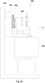
Fig. 1A is a schematic side view of the 3D printing nozzle calibration system ofFig. 1 ; -
Fig. 2 is a flowchart showing the nozzle's calibration process performed by the system ofFig. 1 according to embodiments of the present invention; -
Fig. 3 is a schematic view of a 3D printing nozzle calibration system, printing with a moving printing head/nozzle and a fixed base plate, according to embodiments of the present invention; -
Fig. 3A is a schematic side view of the 3D printing nozzle calibration system ofFig. 3 ; and -
Fig. 4 is a flowchart showing the nozzle's calibration process performed by the system ofFig. 3 according to embodiments of the present invention. - Before explaining at least one embodiment of the invention in detail, it is to be understood that the invention is not limited in its application to the details of construction and the arrangement of the components set forth in the following description or illustrated in the drawings. The invention is applicable to other embodiments or of being practiced or carried out in various ways.
- The present invention provides a system for calibrating a 3D printing nozzle while the nozzle's tip is mounted in a hot (or very hot) environment (e.g., 600 deg C). Throughout the description, 3D printing materials printed inside a heated chamber, such as, glass, metal or any other printing material requiring high melting temperature may be referred to as printing material(s).
- It will be appreciated that the calibration process of the present invention is performed in a system printing using a fixed printing head/nozzle and a moving printing base plate, but this process may also be performed similarly in a system printing using a moving printing head/nozzle and a fixed printing base plate or any other combination of a moving printing nozzle and a moving printing base plate.
- It will be appreciated that the terms "fixed printing nozzle" and "fixed printing base plate" are related to the printing process. During calibration the printing nozzle and/or the printing base plate may be fixed or not.
-
Fig. 1 is a schematic view of a 3D printingnozzle calibration system 100, printing using a fixed printing head/nozzle and a moving printing base plate, according to embodiments of the present invention, comprising: a heated chamber/furnace 105, a printing head (nozzle) 110 partially mounted inside theheated chamber 105, a moving substrate/printing base plate 120 mounted inside theheated chamber 105, movingmeans 106 for moving theprinting base plate 120 in the XYZ planes, a movingcarriage 140 to which theprinting nozzle 110 is connected, at least one linear guide rail 150 (two are shown) on which the movingcarriage 140 is sliding up and down, ahard stop 160 connected to the movingcarriage 140, afixed part 170, defining the nozzle's tip position (the working position), on which thehard stop 160 is resting, and a printer controller (not shown). - The upper side of the
nozzle 110 is mounted outside theheated chamber 105 and the lower side (the nozzle's tip) is mounted inside theheated chamber 105. Thenozzle 110 is connected to the movingcarriage 140 which is mounted outside theheated chamber 105. Thecarriage 140 slides on at least onelinear guide rail 150, parallel to "Z" axis, and enables thenozzle 110 to move up if exposed to a vertical pushing force. Thehard stop 160 connected to thecarriage 140 rests against thefixed part 170 and defines the nozzle's tip position (the working position). According to embodiments of the present invention, thehard stop 160 is connected to one polarity of a simple electric circuit and thefixed part 170 is connected to the other polarity of the same electric circuit. As long as the hard stop rests against thefixed part 170, the electric circuit is closed, namely, the nozzle's tip is at the lower position - working position. When the nozzle moves up, thehard stop 160 disconnects from thefixed part 170 and the electric circuit is opened. When the disconnection happens, the electric circuit sends a signal to the printer controller to record the exact height of the printing base plate.Fig. 1A is a schematic side view of the 3D printingnozzle calibration system 100 of -
Fig. 2 is aflowchart 200 showing the nozzle's calibration process performed by thesystem 100 according to embodiments of the present invention. Instep 210, the printer controller sends a command to the printing base plate moving means to move theprinting base plate 120 in the XY plane to a determined point. Instep 220, when the printing base plate is at the determined point, the printer controller sends a command tothe printing base plate moving means to move theprinting base plate 120 up in the Z axis. When the nozzle's tip touches the printing base plate, thenozzle 110 is pushed up by the printing base plate and thehard stop 160, which is connected to the same moving carriage as thenozzle 110, also moves up and disconnects from thefixed part 170. Instep 230, due to the disconnection, the electric circuit is opened, sends a signal to the printer controller to record the printing base plate's height and the controller sendsa signal to the printing base plate moving means to stop moving up. This Z height parameter is stored in the printer controller. - It will be appreciated that this process may be repeated as desired, in a number of determined points, in order to create a mapping file of the distances between the printing base plate and the nozzle's tip at each one of the determined points of the printing base plate.
- It will be appreciated that the
system 100 may include, instead of the electric circuit, a load cell as the fixed part on which the hard stop is resting. In such a case, the printer controller measures the force made on the load cell and detects degradation of the force when the printing base plate touches the nozzle's tip. - It will be appreciated that other solutions such as a distance sensor, a capacitive base sensor, an IR sensor, laser based sensor, etc. may also be used instead of the electric circuit to detect the disconnection of the
hard stop 160 from thefixed part 170. - As mentioned before, the hard stop defines the nozzle's tip lower position (working position). Sometimes during printing, a retraction of the printing material is required. Theretraction involves a force that may pull the nozzle up, if the nozzle is free to move up on its carriage. According to embodiments of the present invention, in order to prevent that movement, during printing (not during height calibration), an electromagnet (e.g. 180 of
Fig.1 ) or any other type of locking mechanism which can prevent this movement,may be used in order to keep the nozzle's tip locked at working position (e.g., mechanical). In some cases, the electromagnet may be the fixed part (170 ofFig. 1 ) on which the hard stop is resting. In such a case, the hard stop should be formed from a magnetic material (ferromagnetic). - According to embodiments of the present invention, a cleaning station may be used before or during the calibration in order to prevent cases where molten material whichstuck to the nozzle's tip causes the height measurement to be inaccurate. According to embodiments of the present invention, the height calibration process may be performed on a non-planar printing base plate or surface. Since the process may berepeated as desired, a comprehensive mapping file may be generated by calibrating in a large number of points. According to the mapping file, the printer controller may send Z axis corrections to the printing base plate while printing.
- As mentioned above, the described calibration process may be performed in a system printing with a fixed printing head/nozzle and a moving printing base plate and in a system printing with a moving printing head/nozzle and a fixed printing base plate or any other combination of a moving printing nozzle and a moving printing base plate.
-
Fig. 3 is a schematic view of a 3D printingnozzle calibration system 300, printing with amoving printing head/nozzle and a fixed printing base plate, according to embodiments of the present invention, comprising: a heated chamber/furnace 305, a moving printing head (nozzle) 310 partially mounted inside the heated chamber, a substrate/printing base plate 320 mounted inside the heated chamber, a movingcarriage 340 to whichtheprinting nozzle 310 is connected, at least onelinear guide rail 350 on which the moving carriage is sliding up and down (two are shown), aboard 355 on which the at least onelinear guide rail 350 is mounted, ahard stop 360 connected to the movingcarriage 340, a restingpart 370 connected to theboard 355, defining the nozzle's tip position (the working position), on which thehard stop 360 is resting, a printer controller (not shown)and moving means (365 ofFig. 3A ) for moving theboard 355 in the XYZ planes along with theprinting nozzle 310, thecarriage 340, thehard stop 360, the at least onelinear guide rail 350 and the restingpart 370. - As mentioned before, the hard stop defines the nozzle's tip lower position (working position). Sometimes during printing, a retraction of the printing material is required. The retraction involves a force that may pull the nozzle up, if the nozzle is free to move up on its carriage. According to embodiments of the present invention, in order to prevent that movement, during printing (not during height calibration), an electromagnet (e.g. 380 of
Fig.3 ) or any other type of locking mechanism which can prevent this movement, may be used in order to keep the nozzle's tip locked at its current working position (e.g., mechanical). In some cases, the electromagnet may be the resting part (370 ofFig. 3 ) on which the hard stop is resting. In such a case, the hard stop should be formed from amagnetic material (ferromagnetic). -
Fig. 3A is a schematic side view of the 3D printingnozzle calibration system 300 ofFig.3 . -
Fig. 4 is aflowchart 400 showing the nozzle's calibration process performed by thesystem 300 according to embodiments of the present invention. Instep 410, the printer controller sends a command to the printing nozzle moving means to move the printing nozzle in the XY plane to a determined point. Instep 420, when the printing nozzle is at the determined point, the printer controller sends a command to the printing nozzle moving means to move the printing nozzle down in the Z axis. When the nozzle's tip touches the printing base plate, the nozzle is pushed up by the printing base plate and the hard stop, which is connected to the same moving carriage as the nozzle, also moves up and disconnects from the resting part. Instep 430, due to the disconnection, the electric circuit is opened, sends a signal to the printer controller to record the nozzle's height and the controller sends a signal to the printing nozzle moving means tostop moving up. This Z height parameter is stored in the printer controller. - It will be appreciated by persons skilled in the art that the present invention is not limited to what has been particularly shown and described hereinabove. Rather the scope of the present invention is defined by the appended claims.
Claims (15)
- A 3D printing nozzle calibration system (100), comprising:a heated chamber (105);a printing base plate (120) mounted inside said heated chamber (105);printing base moving means (106) configured to move said printing base plate (120);a moving carriage (140);at least one rail (150) on which said moving carriage (140) is configured to slide up and down;a printing nozzle (110) partially mounted inside said heated chamber (105); said printing nozzle (110) is connected to said moving carriage (140);a hard stop (160) connected to said moving carriage (140);a fixed part (170) on which said hard stop (160) is resting; anda printer controller;wherein said printing base plate (120) is configured to move up, up to a point where said printing base plate (120) touches said printing nozzle (110) in a determined point of said printing base plate (120), thereby causing said hard stop (160) to disconnect from said fixed part (170); andwherein said printer controller is configured to store a height of said printing base plate (120) upon said disconnection.
- The 3D printing nozzle calibration system (100) of claim 1, wherein said hard stop is connected to one polarity of an electric circuit and said fixed part (170) is connected to the other polarity of said electric circuit.
- The 3D printing nozzle calibration system (100) of claim 1, wherein said fixed part (170) is a load cell; and wherein said system (100) is further configured to measure the force made on said load cell and to detect degradation of said force when said printing base plate (120) touches said printing nozzle's (110) tip.
- A 3D printing nozzle calibration system (300), comprising:a heated chamber (305);a printing base plate mounted inside said heated chamber (305);a moving carriage (340);a board (355) comprising at least one rail (350) on which said moving carriage (340) is configured to slide up and down;a printing nozzle (310) partially mounted inside said heated chamber (305); said printing nozzle (310) is connected to said moving carriage (340);a hard stop (360) connected to said moving carriage (340);a resting part (370) connected to said board (355), on which said hard stop (360) is resting;printing nozzle moving means (365) configured to move said board (355), said printing nozzle (310), said carriage (340), said hard stop (360) and said resting part (370); anda printer controller;wherein said printing nozzle (310) is configured to move down along with said carriage (340), said hard stop (360) and said resting part (370) above a determined point of said printing base plate (320), up to a point where said printing base plate (320) touches said printing nozzle (310), thereby causing said hard stop (360) to disconnect from said resting part (370); andwherein said printer controller is configured to store a height of said printing nozzle (310) upon said disconnection.
- The 3D printing nozzle calibration system (300) of claim 4, wherein said hard stop (360) is connected to one polarity of an electric circuit and said resting part (370) is connected to the other polarity of said electric circuit.
- The 3D printing nozzle calibration system (300) of claim 4, wherein said resting part (370) is a load cell; and wherein said system (300) is further configured to measure the force made on said load cell and detect degradation of said force when said printing base plate (320) touches said printing nozzle's (310) tip.
- The 3D printing nozzle calibration system (100, 300) of claim 1 or claim 4, wherein said disconnection is detected by one of a distance sensor, a capacitive base sensor, an IR sensor and a laser based sensor.
- The 3D printing nozzle calibration system (100, 300) of claim 1 or claim 4, further comprising a locking mechanism configured to lock said printing nozzle (110, 310) while printing; optionally wherein said locking mechanism comprises one of an electromagnet and a mechanical locking.
- The 3D printing nozzle calibration system (100, 300) of claim 1 or claim 4, wherein said printing base plate (120, 320) is a non-planar printing base plate.
- A process for the calibration of a 3D printing nozzle in a 3D printing nozzle calibration system (100), the 3D printing nozzle calibration system (100) comprising:a printer controller;a heated chamber (105);a printing base plate (120) mounted inside the heated chamber (105);
printing base moving means (106) configured to move the printing base plate (120) in x, y and z planes;a moving carriage (140) and at least one rail (150) on which said moving carriage is configured to slide up and down along a z axis;a printing nozzle (110) partially mounted inside the heated chamber (105) and connected to said moving carriage (140) and displaced from the printing base plate (120) along the z axis,a hard stop (160) also connected to said moving carriage (140) and movable with said printing nozzle (110) along the z axis; anda fixed stop (170) on which the hard stop (160) rests when the printing nozzle (110) is in its printing position;the process comprising:(i) moving the printing base plate (120) upwards towards the printing nozzle (110) towards each other along the z axis until said printing base plate (120) touches said printing nozzle (110) and thereby causing said hard stop (160) to disconnect from said fixed stop (170); and(ii) storing a height of said printing base plate (120) by said printer controller upon said disconnection of said hard stop (160) and said fixed stop (170). - The process for the calibration of a 3D printing nozzle of claim 10, wherein said 3D printing nozzle calibration system (100) comprises a printing base plate moving means (106) for moving said printing base plate (120) along x, y and z axes.
- The process for the calibration of a 3D printing nozzle of claim 10 and 11, comprising moving said printing base plate (120) to a determined x,y location prior to performing steps (i) and (ii).
- The process for the calibration of a 3D printing nozzle of claim 12, comprising: repeating the process of claim 12 to generate a mapping file of the distances between the printing base plate (120) and the printing nozzle (110) at each of a large number of determined points of the printing base plate (120).
- The process for the calibration of a 3D printing nozzle of claim 10, wherein step (i) is performed by the printer controller sending a command to a printing base plate moving means (106) to move the printing base plate up in the z axis.
- A process for the calibration of a 3D printing nozzle in a 3D printing nozzle calibration system (300) comprising:a printer controller;a heated chamber (305);a printing base plate (320) mounted inside the heated chamber (305);a moving carriage (340);a board (355) comprising at least one rail (350) on which the moving carriage (340) is configured to slide up and down along a z axis;a printing nozzle (310) partially mounted inside the heated chamber (305) and connected to said moving carriage (340) and displaced from the printing base plate (320) along the z axis,a hard stop (360) also connected to said moving carriage (340); anda resting part (370) connected to the board (355) on which the hard stop rests (360) when the printing nozzle (310) is in its printing position; andprinting nozzle moving means (365) configured to move the board (355), the printing nozzle (310), the carriage (340), the hard stop (360) and said resting part (370);the process comprising:(i) moving said board (355), said moving carriage (340), said printing nozzle (310), said hard stop (360) and said resting part (370) down along the z axis until said printing nozzle (310) touches said printing base plate (320) and thereby causing said hard stop (360) to disconnect from said resting part (370); and wherein(ii) storing a height of said printing nozzle (310) by said printer controller upon said disconnection of said hard stop (360) and said resting part (370).
Applications Claiming Priority (2)
| Application Number | Priority Date | Filing Date | Title |
|---|---|---|---|
| US201762467258P | 2017-03-06 | 2017-03-06 | |
| PCT/IB2018/051181 WO2018163008A1 (en) | 2017-03-06 | 2018-02-26 | 3d printing nozzle calibration inside a heated chamber |
Publications (3)
| Publication Number | Publication Date |
|---|---|
| EP3592560A1 EP3592560A1 (en) | 2020-01-15 |
| EP3592560A4 EP3592560A4 (en) | 2020-12-23 |
| EP3592560B1 true EP3592560B1 (en) | 2023-12-27 |
Family
ID=63448430
Family Applications (1)
| Application Number | Title | Priority Date | Filing Date |
|---|---|---|---|
| EP18764938.9A Active EP3592560B1 (en) | 2017-03-06 | 2018-02-26 | 3d printing nozzle calibration inside a heated chamber |
Country Status (5)
| Country | Link |
|---|---|
| US (1) | US11167498B2 (en) |
| EP (1) | EP3592560B1 (en) |
| CN (1) | CN110382236B (en) |
| AU (1) | AU2018229975B2 (en) |
| WO (1) | WO2018163008A1 (en) |
Families Citing this family (7)
| Publication number | Priority date | Publication date | Assignee | Title |
|---|---|---|---|---|
| JP7314598B2 (en) * | 2019-04-22 | 2023-07-26 | セイコーエプソン株式会社 | Three-dimensional modeling apparatus and method for manufacturing three-dimensional model |
| CN111267339B (en) * | 2020-02-28 | 2020-09-29 | 上海复志信息技术有限公司 | Method for adjusting height of nozzle of 3D printer |
| CN112571794A (en) * | 2020-12-30 | 2021-03-30 | 广州迈普再生医学科技股份有限公司 | 3D print head needle point positioner and have its 3D print head |
| CN112644022A (en) * | 2021-01-13 | 2021-04-13 | 慧彩增材科技(重庆)有限公司 | Printer nozzle height detection method and nozzle thereof |
| WO2022216572A1 (en) * | 2021-04-07 | 2022-10-13 | Us Synthetic Corporation | Nozzles, nozzle assemblies, and related methods |
| CN116079009B (en) * | 2023-02-03 | 2023-12-01 | 重庆金石智诚科技有限公司 | Clean subassembly and sand mould 3D printer |
| JP2024140099A (en) * | 2023-03-28 | 2024-10-10 | セイコーエプソン株式会社 | 3D modeling equipment |
Family Cites Families (9)
| Publication number | Priority date | Publication date | Assignee | Title |
|---|---|---|---|---|
| US7680555B2 (en) | 2006-04-03 | 2010-03-16 | Stratasys, Inc. | Auto tip calibration in an extrusion apparatus |
| US8153182B2 (en) * | 2008-10-21 | 2012-04-10 | Stratasys, Inc. | Adjustable head mount for digital manufacturing system |
| US9205690B2 (en) * | 2012-03-16 | 2015-12-08 | Stratasys, Inc. | Automated calibration method for additive manufacturing system, and method of use thereof |
| US20160096329A1 (en) * | 2014-10-01 | 2016-04-07 | Flux Technology LLC | 3d tooling machine |
| US20160271871A1 (en) * | 2015-03-17 | 2016-09-22 | Alt Design Co., Ltd. | 3d printing device |
| CN105172133B (en) | 2015-04-17 | 2017-08-11 | 赵舜培 | Method for detecting working state of 3D printer through contact sensing device and 3D printer with contact sensing device |
| CN204749276U (en) * | 2015-05-07 | 2015-11-11 | 杭州捷诺飞生物科技有限公司 | Shower nozzle position calibrating device , system and 3D printing apparatus of 3D printing apparatus |
| US10514678B2 (en) * | 2016-06-28 | 2019-12-24 | Robert Bosch Tool Corporation | Method for leveling a 3-D printing platform and a 3-D platform with adjustable level |
| CN206287520U (en) | 2016-12-22 | 2017-06-30 | 东莞市皇龙电子有限公司 | 3D printer working platform calibration mechanism |
-
2018
- 2018-02-26 EP EP18764938.9A patent/EP3592560B1/en active Active
- 2018-02-26 AU AU2018229975A patent/AU2018229975B2/en not_active Ceased
- 2018-02-26 WO PCT/IB2018/051181 patent/WO2018163008A1/en not_active Ceased
- 2018-02-26 CN CN201880015250.9A patent/CN110382236B/en not_active Expired - Fee Related
- 2018-02-26 US US16/489,549 patent/US11167498B2/en not_active Expired - Fee Related
Also Published As
| Publication number | Publication date |
|---|---|
| EP3592560A4 (en) | 2020-12-23 |
| AU2018229975B2 (en) | 2023-08-03 |
| EP3592560A1 (en) | 2020-01-15 |
| CN110382236A (en) | 2019-10-25 |
| CN110382236B (en) | 2021-10-22 |
| WO2018163008A1 (en) | 2018-09-13 |
| US11167498B2 (en) | 2021-11-09 |
| AU2018229975A1 (en) | 2019-09-19 |
| US20200009794A1 (en) | 2020-01-09 |
Similar Documents
| Publication | Publication Date | Title |
|---|---|---|
| US11167498B2 (en) | 3D printing nozzle calibration inside a heated chamber | |
| KR102454836B1 (en) | Additive Manufacturing Control Systems | |
| US20240253155A1 (en) | Additive manufacturing system with fixed build plate | |
| AU2015202215B2 (en) | 3-D printer having motion sensors | |
| US12186990B2 (en) | Tip calibration in an additive manufacturing system | |
| US11009408B2 (en) | Temperature measurement calibration in an additive manufacturing system | |
| US11994412B2 (en) | Induction sensing method for locating center of metallic nozzle tip | |
| EP4699786A2 (en) | Induction sensing method for locating center of metallic nozzle tip and method of calibrating tip in 3d printer | |
| US20220193996A1 (en) | System for leveling heated platen in 3d printer | |
| EP3145698B1 (en) | System for preparing a 3d printer printout base and a method of preparing a 3d printer printout base | |
| US20200269506A1 (en) | Apparatuses, systems, and methods for performing three-dimensional calibration for additive manufacturing | |
| KR101682600B1 (en) | Apparatus and method for automatic measuring of printhead gap in 3D printer | |
| BR112018072098B1 (en) | Computing apparatus, method and non-transient computer readable medium | |
| NL2023591B1 (en) | Method of determining a local height of a build surface | |
| JP2009532243A (en) | Automatic end calibration in extrusion equipment. | |
| CN111872391A (en) | Selective laser melting forming control system and method | |
| EP3560635A1 (en) | Additive manufacturing system with moveable sensors | |
| US11660674B2 (en) | Contact detection in additive manufacturing | |
| WO2017149308A1 (en) | An additive manufacturing method and system | |
| JP2019130892A (en) | Method for determining position data for device for addition producing three-dimensional article | |
| US20220324029A1 (en) | A powder bed additive manufacturing machine | |
| WO2025105958A1 (en) | Additive manufacturing device using in-line print bed level measurement | |
| CN119319690A (en) | Composite lamination system and method | |
| KR20250067581A (en) | Three-dimension printing device and method | |
| CN119897487A (en) | Additive manufacturing process detection component and method and additive manufacturing equipment and method |
Legal Events
| Date | Code | Title | Description |
|---|---|---|---|
| STAA | Information on the status of an ep patent application or granted ep patent |
Free format text: STATUS: THE INTERNATIONAL PUBLICATION HAS BEEN MADE |
|
| PUAI | Public reference made under article 153(3) epc to a published international application that has entered the european phase |
Free format text: ORIGINAL CODE: 0009012 |
|
| STAA | Information on the status of an ep patent application or granted ep patent |
Free format text: STATUS: REQUEST FOR EXAMINATION WAS MADE |
|
| 17P | Request for examination filed |
Effective date: 20190820 |
|
| AK | Designated contracting states |
Kind code of ref document: A1 Designated state(s): AL AT BE BG CH CY CZ DE DK EE ES FI FR GB GR HR HU IE IS IT LI LT LU LV MC MK MT NL NO PL PT RO RS SE SI SK SM TR |
|
| AX | Request for extension of the european patent |
Extension state: BA ME |
|
| DAV | Request for validation of the european patent (deleted) | ||
| DAX | Request for extension of the european patent (deleted) | ||
| A4 | Supplementary search report drawn up and despatched |
Effective date: 20201120 |
|
| RIC1 | Information provided on ipc code assigned before grant |
Ipc: B33Y 30/00 20150101AFI20201116BHEP Ipc: B29C 64/30 20170101ALI20201116BHEP Ipc: B29C 64/245 20170101ALI20201116BHEP Ipc: B29C 64/232 20170101ALI20201116BHEP Ipc: B29C 64/20 20170101ALI20201116BHEP Ipc: C03B 19/02 20060101ALI20201116BHEP |
|
| GRAP | Despatch of communication of intention to grant a patent |
Free format text: ORIGINAL CODE: EPIDOSNIGR1 |
|
| STAA | Information on the status of an ep patent application or granted ep patent |
Free format text: STATUS: GRANT OF PATENT IS INTENDED |
|
| INTG | Intention to grant announced |
Effective date: 20230710 |
|
| GRAS | Grant fee paid |
Free format text: ORIGINAL CODE: EPIDOSNIGR3 |
|
| GRAA | (expected) grant |
Free format text: ORIGINAL CODE: 0009210 |
|
| STAA | Information on the status of an ep patent application or granted ep patent |
Free format text: STATUS: THE PATENT HAS BEEN GRANTED |
|
| AK | Designated contracting states |
Kind code of ref document: B1 Designated state(s): AL AT BE BG CH CY CZ DE DK EE ES FI FR GB GR HR HU IE IS IT LI LT LU LV MC MK MT NL NO PL PT RO RS SE SI SK SM TR |
|
| REG | Reference to a national code |
Ref country code: GB Ref legal event code: FG4D |
|
| REG | Reference to a national code |
Ref country code: CH Ref legal event code: EP |
|
| REG | Reference to a national code |
Ref country code: DE Ref legal event code: R096 Ref document number: 602018063239 Country of ref document: DE |
|
| REG | Reference to a national code |
Ref country code: IE Ref legal event code: FG4D |
|
| PG25 | Lapsed in a contracting state [announced via postgrant information from national office to epo] |
Ref country code: GR Free format text: LAPSE BECAUSE OF FAILURE TO SUBMIT A TRANSLATION OF THE DESCRIPTION OR TO PAY THE FEE WITHIN THE PRESCRIBED TIME-LIMIT Effective date: 20240328 |
|
| REG | Reference to a national code |
Ref country code: LT Ref legal event code: MG9D |
|
| PG25 | Lapsed in a contracting state [announced via postgrant information from national office to epo] |
Ref country code: LT Free format text: LAPSE BECAUSE OF FAILURE TO SUBMIT A TRANSLATION OF THE DESCRIPTION OR TO PAY THE FEE WITHIN THE PRESCRIBED TIME-LIMIT Effective date: 20231227 |
|
| PG25 | Lapsed in a contracting state [announced via postgrant information from national office to epo] |
Ref country code: ES Free format text: LAPSE BECAUSE OF FAILURE TO SUBMIT A TRANSLATION OF THE DESCRIPTION OR TO PAY THE FEE WITHIN THE PRESCRIBED TIME-LIMIT Effective date: 20231227 |
|
| PG25 | Lapsed in a contracting state [announced via postgrant information from national office to epo] |
Ref country code: LT Free format text: LAPSE BECAUSE OF FAILURE TO SUBMIT A TRANSLATION OF THE DESCRIPTION OR TO PAY THE FEE WITHIN THE PRESCRIBED TIME-LIMIT Effective date: 20231227 Ref country code: GR Free format text: LAPSE BECAUSE OF FAILURE TO SUBMIT A TRANSLATION OF THE DESCRIPTION OR TO PAY THE FEE WITHIN THE PRESCRIBED TIME-LIMIT Effective date: 20240328 Ref country code: FI Free format text: LAPSE BECAUSE OF FAILURE TO SUBMIT A TRANSLATION OF THE DESCRIPTION OR TO PAY THE FEE WITHIN THE PRESCRIBED TIME-LIMIT Effective date: 20231227 Ref country code: ES Free format text: LAPSE BECAUSE OF FAILURE TO SUBMIT A TRANSLATION OF THE DESCRIPTION OR TO PAY THE FEE WITHIN THE PRESCRIBED TIME-LIMIT Effective date: 20231227 Ref country code: BG Free format text: LAPSE BECAUSE OF FAILURE TO SUBMIT A TRANSLATION OF THE DESCRIPTION OR TO PAY THE FEE WITHIN THE PRESCRIBED TIME-LIMIT Effective date: 20240327 |
|
| REG | Reference to a national code |
Ref country code: NL Ref legal event code: MP Effective date: 20231227 |
|
| REG | Reference to a national code |
Ref country code: AT Ref legal event code: MK05 Ref document number: 1644166 Country of ref document: AT Kind code of ref document: T Effective date: 20231227 |
|
| PG25 | Lapsed in a contracting state [announced via postgrant information from national office to epo] |
Ref country code: NL Free format text: LAPSE BECAUSE OF FAILURE TO SUBMIT A TRANSLATION OF THE DESCRIPTION OR TO PAY THE FEE WITHIN THE PRESCRIBED TIME-LIMIT Effective date: 20231227 |
|
| PG25 | Lapsed in a contracting state [announced via postgrant information from national office to epo] |
Ref country code: SE Free format text: LAPSE BECAUSE OF FAILURE TO SUBMIT A TRANSLATION OF THE DESCRIPTION OR TO PAY THE FEE WITHIN THE PRESCRIBED TIME-LIMIT Effective date: 20231227 Ref country code: RS Free format text: LAPSE BECAUSE OF FAILURE TO SUBMIT A TRANSLATION OF THE DESCRIPTION OR TO PAY THE FEE WITHIN THE PRESCRIBED TIME-LIMIT Effective date: 20231227 Ref country code: NO Free format text: LAPSE BECAUSE OF FAILURE TO SUBMIT A TRANSLATION OF THE DESCRIPTION OR TO PAY THE FEE WITHIN THE PRESCRIBED TIME-LIMIT Effective date: 20240327 Ref country code: NL Free format text: LAPSE BECAUSE OF FAILURE TO SUBMIT A TRANSLATION OF THE DESCRIPTION OR TO PAY THE FEE WITHIN THE PRESCRIBED TIME-LIMIT Effective date: 20231227 Ref country code: LV Free format text: LAPSE BECAUSE OF FAILURE TO SUBMIT A TRANSLATION OF THE DESCRIPTION OR TO PAY THE FEE WITHIN THE PRESCRIBED TIME-LIMIT Effective date: 20231227 Ref country code: HR Free format text: LAPSE BECAUSE OF FAILURE TO SUBMIT A TRANSLATION OF THE DESCRIPTION OR TO PAY THE FEE WITHIN THE PRESCRIBED TIME-LIMIT Effective date: 20231227 |
|
| PG25 | Lapsed in a contracting state [announced via postgrant information from national office to epo] |
Ref country code: IS Free format text: LAPSE BECAUSE OF FAILURE TO SUBMIT A TRANSLATION OF THE DESCRIPTION OR TO PAY THE FEE WITHIN THE PRESCRIBED TIME-LIMIT Effective date: 20240427 |
|
| PG25 | Lapsed in a contracting state [announced via postgrant information from national office to epo] |
Ref country code: CZ Free format text: LAPSE BECAUSE OF FAILURE TO SUBMIT A TRANSLATION OF THE DESCRIPTION OR TO PAY THE FEE WITHIN THE PRESCRIBED TIME-LIMIT Effective date: 20231227 Ref country code: AT Free format text: LAPSE BECAUSE OF FAILURE TO SUBMIT A TRANSLATION OF THE DESCRIPTION OR TO PAY THE FEE WITHIN THE PRESCRIBED TIME-LIMIT Effective date: 20231227 |
|
| PG25 | Lapsed in a contracting state [announced via postgrant information from national office to epo] |
Ref country code: SK Free format text: LAPSE BECAUSE OF FAILURE TO SUBMIT A TRANSLATION OF THE DESCRIPTION OR TO PAY THE FEE WITHIN THE PRESCRIBED TIME-LIMIT Effective date: 20231227 |
|
| PG25 | Lapsed in a contracting state [announced via postgrant information from national office to epo] |
Ref country code: SM Free format text: LAPSE BECAUSE OF FAILURE TO SUBMIT A TRANSLATION OF THE DESCRIPTION OR TO PAY THE FEE WITHIN THE PRESCRIBED TIME-LIMIT Effective date: 20231227 Ref country code: SK Free format text: LAPSE BECAUSE OF FAILURE TO SUBMIT A TRANSLATION OF THE DESCRIPTION OR TO PAY THE FEE WITHIN THE PRESCRIBED TIME-LIMIT Effective date: 20231227 Ref country code: RO Free format text: LAPSE BECAUSE OF FAILURE TO SUBMIT A TRANSLATION OF THE DESCRIPTION OR TO PAY THE FEE WITHIN THE PRESCRIBED TIME-LIMIT Effective date: 20231227 Ref country code: IT Free format text: LAPSE BECAUSE OF FAILURE TO SUBMIT A TRANSLATION OF THE DESCRIPTION OR TO PAY THE FEE WITHIN THE PRESCRIBED TIME-LIMIT Effective date: 20231227 Ref country code: IS Free format text: LAPSE BECAUSE OF FAILURE TO SUBMIT A TRANSLATION OF THE DESCRIPTION OR TO PAY THE FEE WITHIN THE PRESCRIBED TIME-LIMIT Effective date: 20240427 Ref country code: EE Free format text: LAPSE BECAUSE OF FAILURE TO SUBMIT A TRANSLATION OF THE DESCRIPTION OR TO PAY THE FEE WITHIN THE PRESCRIBED TIME-LIMIT Effective date: 20231227 Ref country code: CZ Free format text: LAPSE BECAUSE OF FAILURE TO SUBMIT A TRANSLATION OF THE DESCRIPTION OR TO PAY THE FEE WITHIN THE PRESCRIBED TIME-LIMIT Effective date: 20231227 Ref country code: AT Free format text: LAPSE BECAUSE OF FAILURE TO SUBMIT A TRANSLATION OF THE DESCRIPTION OR TO PAY THE FEE WITHIN THE PRESCRIBED TIME-LIMIT Effective date: 20231227 |
|
| PG25 | Lapsed in a contracting state [announced via postgrant information from national office to epo] |
Ref country code: PL Free format text: LAPSE BECAUSE OF FAILURE TO SUBMIT A TRANSLATION OF THE DESCRIPTION OR TO PAY THE FEE WITHIN THE PRESCRIBED TIME-LIMIT Effective date: 20231227 Ref country code: PT Free format text: LAPSE BECAUSE OF FAILURE TO SUBMIT A TRANSLATION OF THE DESCRIPTION OR TO PAY THE FEE WITHIN THE PRESCRIBED TIME-LIMIT Effective date: 20240429 |
|
| PG25 | Lapsed in a contracting state [announced via postgrant information from national office to epo] |
Ref country code: PT Free format text: LAPSE BECAUSE OF FAILURE TO SUBMIT A TRANSLATION OF THE DESCRIPTION OR TO PAY THE FEE WITHIN THE PRESCRIBED TIME-LIMIT Effective date: 20240429 Ref country code: PL Free format text: LAPSE BECAUSE OF FAILURE TO SUBMIT A TRANSLATION OF THE DESCRIPTION OR TO PAY THE FEE WITHIN THE PRESCRIBED TIME-LIMIT Effective date: 20231227 |
|
| REG | Reference to a national code |
Ref country code: DE Ref legal event code: R119 Ref document number: 602018063239 Country of ref document: DE |
|
| PG25 | Lapsed in a contracting state [announced via postgrant information from national office to epo] |
Ref country code: MC Free format text: LAPSE BECAUSE OF FAILURE TO SUBMIT A TRANSLATION OF THE DESCRIPTION OR TO PAY THE FEE WITHIN THE PRESCRIBED TIME-LIMIT Effective date: 20231227 |
|
| REG | Reference to a national code |
Ref country code: CH Ref legal event code: PL |
|
| PG25 | Lapsed in a contracting state [announced via postgrant information from national office to epo] |
Ref country code: DK Free format text: LAPSE BECAUSE OF FAILURE TO SUBMIT A TRANSLATION OF THE DESCRIPTION OR TO PAY THE FEE WITHIN THE PRESCRIBED TIME-LIMIT Effective date: 20231227 |
|
| PG25 | Lapsed in a contracting state [announced via postgrant information from national office to epo] |
Ref country code: LU Free format text: LAPSE BECAUSE OF NON-PAYMENT OF DUE FEES Effective date: 20240226 |
|
| PG25 | Lapsed in a contracting state [announced via postgrant information from national office to epo] |
Ref country code: CH Free format text: LAPSE BECAUSE OF NON-PAYMENT OF DUE FEES Effective date: 20240229 |
|
| PG25 | Lapsed in a contracting state [announced via postgrant information from national office to epo] |
Ref country code: LU Free format text: LAPSE BECAUSE OF NON-PAYMENT OF DUE FEES Effective date: 20240226 Ref country code: DK Free format text: LAPSE BECAUSE OF FAILURE TO SUBMIT A TRANSLATION OF THE DESCRIPTION OR TO PAY THE FEE WITHIN THE PRESCRIBED TIME-LIMIT Effective date: 20231227 Ref country code: CH Free format text: LAPSE BECAUSE OF NON-PAYMENT OF DUE FEES Effective date: 20240229 |
|
| PLBE | No opposition filed within time limit |
Free format text: ORIGINAL CODE: 0009261 |
|
| STAA | Information on the status of an ep patent application or granted ep patent |
Free format text: STATUS: NO OPPOSITION FILED WITHIN TIME LIMIT |
|
| GBPC | Gb: european patent ceased through non-payment of renewal fee |
Effective date: 20240327 |
|
| 26N | No opposition filed |
Effective date: 20240930 |
|
| REG | Reference to a national code |
Ref country code: BE Ref legal event code: MM Effective date: 20240229 |
|
| PG25 | Lapsed in a contracting state [announced via postgrant information from national office to epo] |
Ref country code: DE Free format text: LAPSE BECAUSE OF NON-PAYMENT OF DUE FEES Effective date: 20240903 |
|
| PG25 | Lapsed in a contracting state [announced via postgrant information from national office to epo] |
Ref country code: BE Free format text: LAPSE BECAUSE OF NON-PAYMENT OF DUE FEES Effective date: 20240229 |
|
| PG25 | Lapsed in a contracting state [announced via postgrant information from national office to epo] |
Ref country code: GB Free format text: LAPSE BECAUSE OF NON-PAYMENT OF DUE FEES Effective date: 20240327 |
|
| PG25 | Lapsed in a contracting state [announced via postgrant information from national office to epo] |
Ref country code: FR Free format text: LAPSE BECAUSE OF NON-PAYMENT OF DUE FEES Effective date: 20240227 |
|
| PG25 | Lapsed in a contracting state [announced via postgrant information from national office to epo] |
Ref country code: IE Free format text: LAPSE BECAUSE OF NON-PAYMENT OF DUE FEES Effective date: 20240226 |
|
| PG25 | Lapsed in a contracting state [announced via postgrant information from national office to epo] |
Ref country code: IE Free format text: LAPSE BECAUSE OF NON-PAYMENT OF DUE FEES Effective date: 20240226 Ref country code: GB Free format text: LAPSE BECAUSE OF NON-PAYMENT OF DUE FEES Effective date: 20240327 Ref country code: FR Free format text: LAPSE BECAUSE OF NON-PAYMENT OF DUE FEES Effective date: 20240227 Ref country code: DE Free format text: LAPSE BECAUSE OF NON-PAYMENT OF DUE FEES Effective date: 20240903 Ref country code: BE Free format text: LAPSE BECAUSE OF NON-PAYMENT OF DUE FEES Effective date: 20240229 |
|
| PG25 | Lapsed in a contracting state [announced via postgrant information from national office to epo] |
Ref country code: SI Free format text: LAPSE BECAUSE OF FAILURE TO SUBMIT A TRANSLATION OF THE DESCRIPTION OR TO PAY THE FEE WITHIN THE PRESCRIBED TIME-LIMIT Effective date: 20231227 |
|
| PG25 | Lapsed in a contracting state [announced via postgrant information from national office to epo] |
Ref country code: CY Free format text: LAPSE BECAUSE OF FAILURE TO SUBMIT A TRANSLATION OF THE DESCRIPTION OR TO PAY THE FEE WITHIN THE PRESCRIBED TIME-LIMIT; INVALID AB INITIO Effective date: 20180226 |
|
| PG25 | Lapsed in a contracting state [announced via postgrant information from national office to epo] |
Ref country code: HU Free format text: LAPSE BECAUSE OF FAILURE TO SUBMIT A TRANSLATION OF THE DESCRIPTION OR TO PAY THE FEE WITHIN THE PRESCRIBED TIME-LIMIT; INVALID AB INITIO Effective date: 20180226 |
|
| PG25 | Lapsed in a contracting state [announced via postgrant information from national office to epo] |
Ref country code: TR Free format text: LAPSE BECAUSE OF FAILURE TO SUBMIT A TRANSLATION OF THE DESCRIPTION OR TO PAY THE FEE WITHIN THE PRESCRIBED TIME-LIMIT Effective date: 20231227 |