EP3592517B1 - Coating - Google Patents
Coating Download PDFInfo
- Publication number
- EP3592517B1 EP3592517B1 EP18710402.1A EP18710402A EP3592517B1 EP 3592517 B1 EP3592517 B1 EP 3592517B1 EP 18710402 A EP18710402 A EP 18710402A EP 3592517 B1 EP3592517 B1 EP 3592517B1
- Authority
- EP
- European Patent Office
- Prior art keywords
- nano
- platelets
- materials
- graphene
- coating
- Prior art date
- Legal status (The legal status is an assumption and is not a legal conclusion. Google has not performed a legal analysis and makes no representation as to the accuracy of the status listed.)
- Active
Links
Images

Classifications
-
- C—CHEMISTRY; METALLURGY
- C09—DYES; PAINTS; POLISHES; NATURAL RESINS; ADHESIVES; COMPOSITIONS NOT OTHERWISE PROVIDED FOR; APPLICATIONS OF MATERIALS NOT OTHERWISE PROVIDED FOR
- C09D—COATING COMPOSITIONS, e.g. PAINTS, VARNISHES OR LACQUERS; FILLING PASTES; CHEMICAL PAINT OR INK REMOVERS; INKS; CORRECTING FLUIDS; WOODSTAINS; PASTES OR SOLIDS FOR COLOURING OR PRINTING; USE OF MATERIALS THEREFOR
- C09D127/00—Coating compositions based on homopolymers or copolymers of compounds having one or more unsaturated aliphatic radicals, each having only one carbon-to-carbon double bond, and at least one being terminated by a halogen; Coating compositions based on derivatives of such polymers
- C09D127/02—Coating compositions based on homopolymers or copolymers of compounds having one or more unsaturated aliphatic radicals, each having only one carbon-to-carbon double bond, and at least one being terminated by a halogen; Coating compositions based on derivatives of such polymers not modified by chemical after-treatment
- C09D127/12—Coating compositions based on homopolymers or copolymers of compounds having one or more unsaturated aliphatic radicals, each having only one carbon-to-carbon double bond, and at least one being terminated by a halogen; Coating compositions based on derivatives of such polymers not modified by chemical after-treatment containing fluorine atoms
- C09D127/18—Homopolymers or copolymers of tetrafluoroethene
-
- B—PERFORMING OPERATIONS; TRANSPORTING
- B05—SPRAYING OR ATOMISING IN GENERAL; APPLYING FLUENT MATERIALS TO SURFACES, IN GENERAL
- B05D—PROCESSES FOR APPLYING FLUENT MATERIALS TO SURFACES, IN GENERAL
- B05D1/00—Processes for applying liquids or other fluent materials
- B05D1/02—Processes for applying liquids or other fluent materials performed by spraying
-
- B—PERFORMING OPERATIONS; TRANSPORTING
- B05—SPRAYING OR ATOMISING IN GENERAL; APPLYING FLUENT MATERIALS TO SURFACES, IN GENERAL
- B05D—PROCESSES FOR APPLYING FLUENT MATERIALS TO SURFACES, IN GENERAL
- B05D3/00—Pretreatment of surfaces to which liquids or other fluent materials are to be applied; After-treatment of applied coatings, e.g. intermediate treating of an applied coating preparatory to subsequent applications of liquids or other fluent materials
- B05D3/02—Pretreatment of surfaces to which liquids or other fluent materials are to be applied; After-treatment of applied coatings, e.g. intermediate treating of an applied coating preparatory to subsequent applications of liquids or other fluent materials by baking
- B05D3/0254—After-treatment
-
- B—PERFORMING OPERATIONS; TRANSPORTING
- B05—SPRAYING OR ATOMISING IN GENERAL; APPLYING FLUENT MATERIALS TO SURFACES, IN GENERAL
- B05D—PROCESSES FOR APPLYING FLUENT MATERIALS TO SURFACES, IN GENERAL
- B05D5/00—Processes for applying liquids or other fluent materials to surfaces to obtain special surface effects, finishes or structures
- B05D5/08—Processes for applying liquids or other fluent materials to surfaces to obtain special surface effects, finishes or structures to obtain an anti-friction or anti-adhesive surface
- B05D5/083—Processes for applying liquids or other fluent materials to surfaces to obtain special surface effects, finishes or structures to obtain an anti-friction or anti-adhesive surface involving the use of fluoropolymers
-
- B—PERFORMING OPERATIONS; TRANSPORTING
- B05—SPRAYING OR ATOMISING IN GENERAL; APPLYING FLUENT MATERIALS TO SURFACES, IN GENERAL
- B05D—PROCESSES FOR APPLYING FLUENT MATERIALS TO SURFACES, IN GENERAL
- B05D7/00—Processes, other than flocking, specially adapted for applying liquids or other fluent materials to particular surfaces or for applying particular liquids or other fluent materials
- B05D7/14—Processes, other than flocking, specially adapted for applying liquids or other fluent materials to particular surfaces or for applying particular liquids or other fluent materials to metal, e.g. car bodies
-
- B—PERFORMING OPERATIONS; TRANSPORTING
- B26—HAND CUTTING TOOLS; CUTTING; SEVERING
- B26B—HAND-HELD CUTTING TOOLS NOT OTHERWISE PROVIDED FOR
- B26B21/00—Razors of the open or knife type; Safety razors or other shaving implements of the planing type; Hair-trimming devices involving a razor-blade; Equipment therefor
- B26B21/54—Razor-blades
- B26B21/58—Razor-blades characterised by the material
- B26B21/60—Razor-blades characterised by the material by the coating material
-
- C—CHEMISTRY; METALLURGY
- C08—ORGANIC MACROMOLECULAR COMPOUNDS; THEIR PREPARATION OR CHEMICAL WORKING-UP; COMPOSITIONS BASED THEREON
- C08K—Use of inorganic or non-macromolecular organic substances as compounding ingredients
- C08K3/00—Use of inorganic substances as compounding ingredients
- C08K3/02—Elements
- C08K3/04—Carbon
- C08K3/041—Carbon nanotubes
-
- C—CHEMISTRY; METALLURGY
- C09—DYES; PAINTS; POLISHES; NATURAL RESINS; ADHESIVES; COMPOSITIONS NOT OTHERWISE PROVIDED FOR; APPLICATIONS OF MATERIALS NOT OTHERWISE PROVIDED FOR
- C09D—COATING COMPOSITIONS, e.g. PAINTS, VARNISHES OR LACQUERS; FILLING PASTES; CHEMICAL PAINT OR INK REMOVERS; INKS; CORRECTING FLUIDS; WOODSTAINS; PASTES OR SOLIDS FOR COLOURING OR PRINTING; USE OF MATERIALS THEREFOR
- C09D7/00—Features of coating compositions, not provided for in group C09D5/00; Processes for incorporating ingredients in coating compositions
- C09D7/40—Additives
- C09D7/60—Additives non-macromolecular
- C09D7/61—Additives non-macromolecular inorganic
-
- C—CHEMISTRY; METALLURGY
- C09—DYES; PAINTS; POLISHES; NATURAL RESINS; ADHESIVES; COMPOSITIONS NOT OTHERWISE PROVIDED FOR; APPLICATIONS OF MATERIALS NOT OTHERWISE PROVIDED FOR
- C09D—COATING COMPOSITIONS, e.g. PAINTS, VARNISHES OR LACQUERS; FILLING PASTES; CHEMICAL PAINT OR INK REMOVERS; INKS; CORRECTING FLUIDS; WOODSTAINS; PASTES OR SOLIDS FOR COLOURING OR PRINTING; USE OF MATERIALS THEREFOR
- C09D7/00—Features of coating compositions, not provided for in group C09D5/00; Processes for incorporating ingredients in coating compositions
- C09D7/40—Additives
- C09D7/66—Additives characterised by particle size
- C09D7/67—Particle size smaller than 100 nm
-
- C—CHEMISTRY; METALLURGY
- C09—DYES; PAINTS; POLISHES; NATURAL RESINS; ADHESIVES; COMPOSITIONS NOT OTHERWISE PROVIDED FOR; APPLICATIONS OF MATERIALS NOT OTHERWISE PROVIDED FOR
- C09D—COATING COMPOSITIONS, e.g. PAINTS, VARNISHES OR LACQUERS; FILLING PASTES; CHEMICAL PAINT OR INK REMOVERS; INKS; CORRECTING FLUIDS; WOODSTAINS; PASTES OR SOLIDS FOR COLOURING OR PRINTING; USE OF MATERIALS THEREFOR
- C09D7/00—Features of coating compositions, not provided for in group C09D5/00; Processes for incorporating ingredients in coating compositions
- C09D7/40—Additives
- C09D7/66—Additives characterised by particle size
- C09D7/68—Particle size between 100-1000 nm
-
- C—CHEMISTRY; METALLURGY
- C09—DYES; PAINTS; POLISHES; NATURAL RESINS; ADHESIVES; COMPOSITIONS NOT OTHERWISE PROVIDED FOR; APPLICATIONS OF MATERIALS NOT OTHERWISE PROVIDED FOR
- C09D—COATING COMPOSITIONS, e.g. PAINTS, VARNISHES OR LACQUERS; FILLING PASTES; CHEMICAL PAINT OR INK REMOVERS; INKS; CORRECTING FLUIDS; WOODSTAINS; PASTES OR SOLIDS FOR COLOURING OR PRINTING; USE OF MATERIALS THEREFOR
- C09D7/00—Features of coating compositions, not provided for in group C09D5/00; Processes for incorporating ingredients in coating compositions
- C09D7/40—Additives
- C09D7/70—Additives characterised by shape, e.g. fibres, flakes or microspheres
-
- B—PERFORMING OPERATIONS; TRANSPORTING
- B05—SPRAYING OR ATOMISING IN GENERAL; APPLYING FLUENT MATERIALS TO SURFACES, IN GENERAL
- B05D—PROCESSES FOR APPLYING FLUENT MATERIALS TO SURFACES, IN GENERAL
- B05D2202/00—Metallic substrate
- B05D2202/10—Metallic substrate based on Fe
- B05D2202/15—Stainless steel
-
- B—PERFORMING OPERATIONS; TRANSPORTING
- B05—SPRAYING OR ATOMISING IN GENERAL; APPLYING FLUENT MATERIALS TO SURFACES, IN GENERAL
- B05D—PROCESSES FOR APPLYING FLUENT MATERIALS TO SURFACES, IN GENERAL
- B05D2601/00—Inorganic fillers
- B05D2601/20—Inorganic fillers used for non-pigmentation effect
-
- C—CHEMISTRY; METALLURGY
- C08—ORGANIC MACROMOLECULAR COMPOUNDS; THEIR PREPARATION OR CHEMICAL WORKING-UP; COMPOSITIONS BASED THEREON
- C08K—Use of inorganic or non-macromolecular organic substances as compounding ingredients
- C08K3/00—Use of inorganic substances as compounding ingredients
- C08K3/30—Sulfur-, selenium- or tellurium-containing compounds
- C08K2003/3009—Sulfides
-
- C—CHEMISTRY; METALLURGY
- C08—ORGANIC MACROMOLECULAR COMPOUNDS; THEIR PREPARATION OR CHEMICAL WORKING-UP; COMPOSITIONS BASED THEREON
- C08K—Use of inorganic or non-macromolecular organic substances as compounding ingredients
- C08K3/00—Use of inorganic substances as compounding ingredients
- C08K3/02—Elements
- C08K3/04—Carbon
-
- C—CHEMISTRY; METALLURGY
- C08—ORGANIC MACROMOLECULAR COMPOUNDS; THEIR PREPARATION OR CHEMICAL WORKING-UP; COMPOSITIONS BASED THEREON
- C08K—Use of inorganic or non-macromolecular organic substances as compounding ingredients
- C08K3/00—Use of inorganic substances as compounding ingredients
- C08K3/02—Elements
- C08K3/04—Carbon
- C08K3/042—Graphene or derivatives, e.g. graphene oxides
-
- C—CHEMISTRY; METALLURGY
- C08—ORGANIC MACROMOLECULAR COMPOUNDS; THEIR PREPARATION OR CHEMICAL WORKING-UP; COMPOSITIONS BASED THEREON
- C08K—Use of inorganic or non-macromolecular organic substances as compounding ingredients
- C08K3/00—Use of inorganic substances as compounding ingredients
- C08K3/02—Elements
- C08K3/04—Carbon
- C08K3/046—Carbon nanorods, nanowires, nanoplatelets or nanofibres
Definitions
- the following description relates to coatings applied to the blade of a shaving razor.
- the coating includes an organic material reinforced by one or more nano-materials.
- Conventional coatings applied to the blade of shaving razors include polytetrafluoroethylene (PTFE) as a lubricating component.
- PTFE polytetrafluoroethylene
- the dispersions having PTFE can be applied and sintered onto shaving blades.
- the coating provides lubrication and reduces the friction between the blade and the hair and skin from that of an uncoated blade surface.
- WO 2010/081119 A1 discloses a razor blade coated with a nanocomposite coating comprising nanodiamonds and PTFE.
- the present PTFE coatings still produce more friction between the blade, hair, and skin than desired. Further, several disadvantages are typically encountered including insufficient lubrication of razor blades, leading to poor shaving performance.
- the present description provides a nanocomposite coating, comprising nano-materials and organic solids, that overcomes the aforementioned disadvantages of conventional shaving blade coatings.
- the nanocomposite coating generally includes a nano-material mixture; the nano-material mixture as described herein may be a dispersion of one or more nano- materials throughout a suitable medium in order to create a dispersion that may be used to form a lubricating coating on a desired surface.
- the one or more nano-materials may be, but are not limited to, carbon-based nano-materials including, graphene nano-platelets, graphite nano-platelets, oxidized graphene nano-platelets, oxidized graphite nano-platelets, large area graphene sheets, and carbon nanotubes (CNTs), thick and thin two-dimensional materials including, but not limited to, graphene, boron nitride (BN), tungsten (IV) sulfide (WS2), and molybdenum disulfide (MoS2), van der Waals heterostructures such as layer-by-layer stacks of two-dimensional materials, suitable hybrid compounds such as a mixture of suitable combinations of carbon-based nano-materials and other two-dimensional materials, and any other suitable nano-material.
- carbon-based nano-materials including, graphene nano-platelets, graphite nano-platelets, oxidized graphene nano-platelets, oxidized graphite nano-platelets, large area graphene sheets, and
- the surface on which the final solution/mixture is applied may be, but is not limited to, a blade edge such as a stainless-steel strip having at least one cutting edge and a hard coating.
- a solution/mixture made in accordance with the disclosure herein may also include an organic material, such as polyfluorocarbon including, but not limited to, PTFE nanoparticles.
- the solution/mixture may be prepared, diluted, applied, and sintered onto the desired surface.
- the nanocomposite coating may act, but is not bound, as a lubricating (or soft) coating for a blade.
- a razor having one or more blades and a coating disposed on at least one of the one or more blades.
- the coating may include one or more nano-materials selected from the group consisting of carbon-based nano-materials, two-dimensional materials, van der Waals heterostructures, hybrid compounds, and combinations thereof; and an organic material.
- the one or more nano- materials may be present in a concentration of up to 30% by weight, based on the total weight of the coating and in that the carbon-based nano-materials are selected from the group consisting of graphene nano-platelets, graphite nano-platelets, oxidized graphene nano-platelets, oxidized graphite nano-platelets, large area graphene sheets, carbon nanotubes (CNTs), and combinations thereof.
- the blade may be a strip of stainless steel, having at least one cutting edge.
- the present disclosure may be achieved by providing a method for coating a razor blade comprising mixing one or more nano-materials and a suitable medium with an organic material to achieve a dispersion, diluting the dispersion with a suitable diluent, depositing the diluted solution onto a razor blade, and sintering the razor blade after the diluted solution is disposed onto the razor blade, where the one or more nano-materials are selected from the group consisting of carbon-based nano-materials selected from the group consisting of graphene nano-platelets, graphite nano-platelets, oxidized graphene nano- platelets, oxidized graphite nano-platelets, large area graphene sheets, carbon nanotubes (CNTs), and combinations thereof, two-dimensional materials, van der Waals heterostructures, hybrid compounds, and combinations thereof.
- the one or more nano-materials are selected from the group consisting of carbon-based nano-materials selected from the group consisting of graphene nano-platelets, graphite nano-platelets, oxidized
- the dispersion may have a nano-material concentration from about 0% to about 10% by weight and an organic material concentration of about 20% by weight, based on the total weight of the dispersion.
- the diluted solution may have a nano- material concentration of about 0% to about 0.6% by weight and an organic material concentration of less than about 2% by weight, based on the total weight of the diluted solution.
- the razor blade has a hard coating.
- any term of degree such as, but not limited to, "about” or “approximately,” as used in the description and the appended claims, should be understood to include the recited values or a value that is three times greater or one third of the recited values.
- about 3 mm includes all values from 1 mm to 9 mm, and approximately 50 degrees includes all values from 16.6 degrees to 150 degrees.
- graphene nano-platelets as used herein is defined as including both single layer and multi-layer (such as, few layer) planar sheets interacting by van der Waals forces with an average thickness of up to about 10nm and a lateral size of up to about 100 ⁇ m.
- graphite nano-platelets as used herein is defined as including crystals with a thickness of greater than about 10nm.
- large area graphene sheets is defined as the material grown on thin metallic substrates under a chemical vapor deposition process; providing a surface area of greater than about 5cm 2 .
- oxidized graphene and “oxidized graphite” refer to “graphene oxide nano-platelets” and “graphite oxide nano-platelets”, respectively.
- graphene oxide nano-platelets as used herein is defined as including both single layer and multi-layer (such as, few layer) planar sheets interacting by van der Waals forces with an average thickness of up to about 10nm and a lateral size of up to about 100 ⁇ m.
- graphite oxide nano-platelets as used herein is defined as including crystals with a thickness of greater than about 10nm deposition process; providing a surface area of greater than about 5cm 2 .
- CNTs carbon nanotubes
- multi- walled concentric graphene tubes
- thin 2-D materials as used herein is defined as including both single layer and multi-layered (such as, few layered) planar sheets interacting by van der Waals forces, wherein the sheets have an average thickness of up to about 10nm and a lateral size of up to about 5 ⁇ m.
- crystals having a thickness of greater than about 10nm are referred to herein as "thick 2-D materials”.
- van der Waals heterostructures as used herein is defined as the layer-by-layer stacking of different 2-D materials.
- hybrid compounds as used herein is defined as materials made by mixing suitable combinations of graphene nano-platelets, graphite nano-platelets, and CNTs with other 2-D materials.
- organic material may include a lubricating material, such as a hydrophobic or hydrophilic lubricating material.
- suitable medium may include, but is not limited to, a pure organic solvent, a pure inorganic solvent, a surface-active agent or any combination thereof.
- nanocomposite coating refers to a sintered coating comprising a combination of at least one nano-material and an organic material.
- nano-material may refer to carbon based nano-materials, thin two-dimensional materials, thick two-dimensional materials, van der Waals heterostructures, and hybrid compounds.
- carbon based nano-material may refer to, but is not limited to, graphene nano-platelets, graphite nano-platelets, large area graphene sheets, graphene oxide nano-platelets, graphite oxide nano-platelets, carbon nanotubes (CNTs).
- CNTs carbon nanotubes
- references to the terms “embodiment,” “embodiments,” and/or the like in the description mean that the feature and/or features being referred to are included in, at least, one aspect of the description.
- Separate references to the terms “embodiment,” “embodiments,” and/or the like in the description do not necessarily refer to the same embodiment and are also not mutually exclusive unless so stated and/or except as will be readily apparent to those skilled in the art from the description.
- a feature, structure, process, step, action, or the like described in one embodiment may also be included in other embodiments, but is not necessarily included.
- the present inventive concept may include a variety of combinations and/or integrations of the embodiments described herein.
- the nano-material mixture as described herein may be a dispersion of one or more nano-materials throughout a suitable medium.
- the one or more nano-materials may be, but are not limited to, carbon-based nano-materials (including, but not limited to, graphene nano- platelets, graphite nano-platelets, oxidized graphene nano-platelets, oxidized graphite nano- platelets, large area graphene sheets, and carbon nanotubes (CNTs)), thick and thin two- dimensional materials (including, but not limited to, graphene, boron nitride (BN), tungsten (IV) sulfide (WS2), and molybdenum disulfide (MoS2)), suitable hybrid compounds (including, but not limited to, materials made by mixing suitable combinations of graphene/ graphite nano-platelets, CNTs with other 2-D materials), and van der Waals heterostructures (including, but not limited to, layer-by-layer stacks of different 2-D materials, such as graphen
- nano-materials generally described herein are referred to as powders, it would be understood by those having skill in the art that the previously described materials may be included in powder form or dispersed within a suitable medium (including, but not limited to, water, an ethanol and water mixture, or any other suitable organic solvents).
- a suitable medium including, but not limited to, water, an ethanol and water mixture, or any other suitable organic solvents.
- Graphene nano- platelets and graphite nano-platelets powders compatible for use in the present nanocomposite coating may include those which are commercially available in a variety of sizes and thicknesses.
- the graphene nano-platelets compatible for use with the coatings described herein may have a lateral size of from about 0.25 ⁇ m to about 100 ⁇ m and a thickness of from about 0.34nm (such as a single layer) up to about 10nm (such as multi-layered nano- platelets).
- the graphite nano-platelets compatible for use with the coatings described herein may have a nano-platelet lateral size of from about 0.25 ⁇ m to about 100 ⁇ m and a nano-platelet thickness of greater than about 10nm.
- the nano-materials may be dispersed throughout a suitable medium.
- the suitable medium may be water, such as deionized water.
- the concentration of the nano-material/aqueous mixture may be from about 0 grams per milliliter (gr/mL) to about 5 gr/mL by weight nano-material, based on a total weight of the nano-material/aqueous mixture.
- a second mixture may be added to the above described nano-material/aqueous mixture.
- the second mixture (also referred to herein as an "organic material dispersion”) may be a dispersion of an organic material throughout a suitable medium.
- the organic material may be a polyfluorocarbon, including, but not limited to, polytetrafluoroethylene (PTFE) is dispersed within de-ionized H 2 O and surfactant, having a PTFE solids concentration of about 20% by weight, based on the total weight of the second mixture (also referred to herein as a "PTFE dispersion").
- PTFE dispersions are commercially available from companies, including, but not limited to, the Chemours Company (such as the LW2120 dispersion).
- the nano-material/aqueous mixture is added to the organic material dispersion using methods including, but not limited to, magnetic stirring and tip sonication techniques.
- the resulting organic material/nano-material mixture (also referred to herein as the "initial mixture") may be created in a wide variety of concentrations including, but not limited to, from about 0% to about 10% gr/mL nano-material and about 20% by weight organic material, based on the total weight of the initial organic material/nano-material mixture.
- the dispersion may be loaded into a roll mixer, or other suitable mixing device, to obtain a dispersion of the nano-materials throughout the aqueous-based organic material mixture.
- a second mixing step may help to prevent the agglomeration of nano-materials within the dispersion.
- the initial mixture may be diluted using de-ionized water, or any other suitable diluent, to achieve the desired concentration for the final organic material/nano-material mixture.
- the final concentration of the diluted dispersion may be, but is not limited to, from about 0.0% to about 0.6% by weight nano-materials and less than about 2% by weight organic material, based on the total weight of the final organic material/nano-material mixture.
- the initial organic material/nano-material mixture may be more structured.
- the nano-material may be, but is not limited to, sheets of aligned graphene, providing a reinforcement material for the final coating.
- the nano-composite coating may then include stacks, or layers, of the aligned graphene sheets and organic matrix material.
- the nano-composite coating may include a combination of the unstructured and structured examples described above.
- the diluted dispersion may be applied to any desired surface using one of many different methods including, but not limited to, spraying, dipping, lamination, and any other suitable coating technique.
- the desired surface may include, but is not limited to, a plurality of razor blades, and individual stainless steel strips having a cutting edge.
- spraying of the final mixture may be completed by, but not limited to, airless, air-assisted, air spray, or various other spraying methods.
- the final mixture may be disposed on the desired surface using a coating system.
- the coating system may include a tank, holding the final organic material/nano- material mixture, and a stirrer, to keep the mixture under constant motion to maintain a homogenous dispersion.
- the tank may be connected to an air supply and a pump via a pipe, to create pressurization within the tank and allow for a pressurized flow of the mixture out of a spray gun in fluidic communication with the tank.
- the spray gun may be, but is not limited to, a low pressure spray gun, and may use air pressure and fluid pressure to achieve the desired atomization of the final mixture.
- the spray gun may be configured to produce a mist of fine particles of the final mixture to be disposed on the desired surface; the size and reparation of the particles may be adjusted by using different air-caps on the end of the spray gun.
- the coating may be applied to a surface in accordance with methods as described in WO 2011047727 , included herein by reference in its entirety.
- the coating may be sintered.
- Sintering may be completed through the use of, but is not limited to, resistance, ultraviolet (UV) light, infrared (IR) light, flash lamps, and any other suitable sintering processes.
- the sintering process may be completed, for example, by heating the coated surface at a temperature of 360 °C until the organic material is melted, leaving only the desired nanocomposite coating, comprising only the nano-materials and the organic material solids, disposed on the surface.
- the nanocomposite coating may have a nano-material concentration of from about 0% to about 30% by weight, based on a total weight of the nanocomposite coating.
- the sintered nanocomposite coating may be analyzed using a variety of different methods to determine specific characteristics of the coating. For example, morphological characteristics may be evaluated using optical microscopy (OM) and scanning electron microscopy (SEM). Additionally, the frictional characteristics of the sintered coating may be evaluated using a friction test. The friction test may measure resistance to dragging, the force developed when a coated surface is dragged over a specified material (such as a specific type of paper for a predetermined distance). In the alternative, frictional characteristics may be measured using a dry and/or wet felt test. For example, when the coating is applied to a blade edge, the test may include a determination of the cutting force developed on the blade during a series of continuous cuts on a moving dry or wet felt. Finally, a Thermogravimetric analysis (TGA) was used, Q50 TA Insts ® , in order to quantify the concentration of the nano-material into the nanocomposite coating.
- TGA Thermogravimetric analysis
- An in-depth analysis of coating may also be performed using Differential Scanning Calorimetry (DSC), Raman microscopy, and Atomic Force microscopy (AFM).
- DSC Differential Scanning Calorimetry
- Raman microscopy was performed using a Renishaw ® Invia 2000 at 785nm to identify the quality of the nano- material used, the organic material/nano-material interactions, and, where possible, were used to define the thickness of the nano-material inclusions.
- Raman microscopy was used to detect possible structure changes on organic materials after the incorporation of the nano-material.
- Atomic Force microscopy performed on a Bruker ® FastScan was used to perform topographic analysis of the coating after deposition on the blades.
- the initial PTFE/graphene nano-platelets mixture had a concentration of about 1% gram/mL of graphene nano-platelets and about 20% by weight PTFE, based on a total weight of the initial PTFE/graphene nano-platelets mixture.
- the initial mixture was then diluted to a lower concentration using de-ionized water.
- the concentration of the diluted mixture was determined to be about 0.06% by weight graphene nano-platelets and about 1.2% by weight PTFE, based on a total weight of the final PTFE/graphene nano-platelets mixture.
- the final PTFE/graphene nano-platelets dispersion was then sprayed onto a razor blade surface using a commercially available production spray system.
- the razor blade was an individual strip of stainless steel having a cutting edge with a specific grinding profile, wherein the blade is covered in a hard coating material.
- the spray system includes, as described above, a pressurized tank having a stirrer in order to maintain homogenous dispersion of the particles throughout the final mixture.
- the tank is in fluidic communication with a spray gun having a nozzle that allows for a pressurized mist of the final mixture to be disposed on the blade to a desired thickness.
- the coated blade was then sintered in a resistance heating oven by heating the blades at 360 °C to melt the PTFE nano-particles and leave the desired nanocomposite coating on the blades. Once sintered, the coated blades were left with a 4.76% by weight graphene nano-platelets, based on the total weight of the graphene nano-platelets/PTFE nanocomposite coating.
- the initial PTFE/graphene nano-platelets mixture had a concentration of about 0.25% gram/mL of graphene nano-platelets and about 20% by weight PTFE, based on a total weight of the initial mixture.
- the initial mixture was diluted to a lower concentration using de-ionized water.
- the concentration of the final PTFE/graphene nano-platelets mixture was about 0.015% gram/mL graphene nano-platelets and about 1.2% by weight PTFE, based on a total weight of the final mixture.
- the final PTFE/graphene nano-platelets mixture was then sprayed onto a razor blade surface using a commercially available production spray system.
- the razor blade was an individual strip of stainless steel having a cutting edge with a specific grinding profile, wherein the blade is covered in a hard coating material.
- the spray system includes, as described above, a pressurized tank having a stirrer in order to maintain homogenous dispersion of the particles throughout the final mixture.
- the tank is in fluidic communication with a spray gun having a nozzle that allows for a pressurized mist of the final mixture to be disposed on the blade to a desired thickness.
- the coated blade was then sintered in a resistance heating oven by heating the coated blade to 360 °C to melt the PTFE nano-particles and leave the blade coated with the desired nanocomposite.
- the coated blades are left with a 1.23% by weight graphene nano-platelets, based on the total weight of the graphene nano-platelets/PTFE nanocomposite coating.
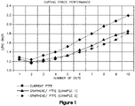
- Figure 1 illustrates the cutting force performance of each of the three different samples.
- the value of the first cut loads of Examples 1 and 2 is measured to be about 4-5% lower than the blade produced using the standard PTFE coating. Additionally, the tenth cutloads delivered by the blades coated with the Example 1 and 2 coatings were about 15-17% lower than the corresponding load values of the standard PTFE coated blade. Specifically, the values of cut force for the first and tenth cut are shown in Table 1, below.
- Table 1 Sample Force at 1 st Cut (Kgf) Force at 10 th Cut (Kgf) Standard PTFE Coating 1.291 2.194
- Figure 2 illustrates the results of the friction force performance tests.
- the coatings as prepared by Examples 1 and 2 provide about a 5-7% decrease of the MAX load developed during the friction test single stroke measurement compared to the standard PTFE coated blade.
- the MAX value of friction force for each coated blade is shown in Table 2, below.
- Table 2 Sample MAX Value of Friction Force ⁇ 10 -3 (Kgf) Standard PTFE Coating 10.9
Landscapes
- Chemical & Material Sciences (AREA)
- Engineering & Computer Science (AREA)
- Life Sciences & Earth Sciences (AREA)
- Organic Chemistry (AREA)
- Materials Engineering (AREA)
- Wood Science & Technology (AREA)
- Nanotechnology (AREA)
- Medicinal Chemistry (AREA)
- Health & Medical Sciences (AREA)
- Chemical Kinetics & Catalysis (AREA)
- Polymers & Plastics (AREA)
- Mechanical Engineering (AREA)
- Forests & Forestry (AREA)
- Inorganic Chemistry (AREA)
- Carbon And Carbon Compounds (AREA)
- Lubricants (AREA)
- Paints Or Removers (AREA)
- Polarising Elements (AREA)
- Polymers With Sulfur, Phosphorus Or Metals In The Main Chain (AREA)
Description
- The following description relates to coatings applied to the blade of a shaving razor. The coating includes an organic material reinforced by one or more nano-materials.
- Conventional coatings applied to the blade of shaving razors include polytetrafluoroethylene (PTFE) as a lubricating component. The dispersions having PTFE can be applied and sintered onto shaving blades. The coating, provides lubrication and reduces the friction between the blade and the hair and skin from that of an uncoated blade surface.
-
WO 2010/081119 A1 , for example, discloses a razor blade coated with a nanocomposite coating comprising nanodiamonds and PTFE. - However, the present PTFE coatings still produce more friction between the blade, hair, and skin than desired. Further, several disadvantages are typically encountered including insufficient lubrication of razor blades, leading to poor shaving performance.
- The present description provides a nanocomposite coating, comprising nano-materials and organic solids, that overcomes the aforementioned disadvantages of conventional shaving blade coatings. The nanocomposite coating generally includes a nano-material mixture; the nano-material mixture as described herein may be a dispersion of one or more nano- materials throughout a suitable medium in order to create a dispersion that may be used to form a lubricating coating on a desired surface. The one or more nano-materials may be, but are not limited to, carbon-based nano-materials including, graphene nano-platelets, graphite nano-platelets, oxidized graphene nano-platelets, oxidized graphite nano-platelets, large area graphene sheets, and carbon nanotubes (CNTs), thick and thin two-dimensional materials including, but not limited to, graphene, boron nitride (BN), tungsten (IV) sulfide (WS2), and molybdenum disulfide (MoS2), van der Waals heterostructures such as layer-by-layer stacks of two-dimensional materials, suitable hybrid compounds such as a mixture of suitable combinations of carbon-based nano-materials and other two-dimensional materials, and any other suitable nano-material. The surface on which the final solution/mixture is applied may be, but is not limited to, a blade edge such as a stainless-steel strip having at least one cutting edge and a hard coating. A solution/mixture made in accordance with the disclosure herein may also include an organic material, such as polyfluorocarbon including, but not limited to, PTFE nanoparticles. The solution/mixture may be prepared, diluted, applied, and sintered onto the desired surface. The nanocomposite coating may act, but is not bound, as a lubricating (or soft) coating for a blade.
- Another aspect of the present disclosure may be achieved by providing a razor having one or more blades and a coating disposed on at least one of the one or more blades. The coating may include one or more nano-materials selected from the group consisting of carbon-based nano-materials, two-dimensional materials, van der Waals heterostructures, hybrid compounds, and combinations thereof; and an organic material. The one or more nano- materials may be present in a concentration of up to 30% by weight, based on the total weight of the coating and in that the carbon-based nano-materials are selected from the group consisting of graphene nano-platelets, graphite nano-platelets, oxidized graphene nano-platelets, oxidized graphite nano-platelets, large area graphene sheets, carbon nanotubes (CNTs), and combinations thereof. The blade may be a strip of stainless steel, having at least one cutting edge.
- In yet another aspect, the present disclosure may be achieved by providing a method for coating a razor blade comprising mixing one or more nano-materials and a suitable medium with an organic material to achieve a dispersion, diluting the dispersion with a suitable diluent, depositing the diluted solution onto a razor blade, and sintering the razor blade after the diluted solution is disposed onto the razor blade, where the one or more nano-materials are selected from the group consisting of carbon-based nano-materials selected from the group consisting of graphene nano-platelets, graphite nano-platelets, oxidized graphene nano- platelets, oxidized graphite nano-platelets, large area graphene sheets, carbon nanotubes (CNTs), and combinations thereof, two-dimensional materials, van der Waals heterostructures, hybrid compounds, and combinations thereof. The dispersion may have a nano-material concentration from about 0% to about 10% by weight and an organic material concentration of about 20% by weight, based on the total weight of the dispersion. The diluted solution may have a nano- material concentration of about 0% to about 0.6% by weight and an organic material concentration of less than about 2% by weight, based on the total weight of the diluted solution. The razor blade has a hard coating.
- The foregoing is intended to be illustrative and is not meant in a limiting sense. Many features of the embodiments may be employed with or without reference to other features of any of the embodiments. Additional aspects, advantages, and/or utilities of the present inventive concept will be set forth, in part, in the description that follows and, in part, will be apparent from the description, or may be learned by practice of the present inventive concept.
- The foregoing summary, as well as the following detailed description, will be better understood when read in conjunction with the appended drawings. For the purpose of illustration, there are shown in the drawings certain embodiments of the present disclosure. It should be understood, however, that the present inventive concept is not limited to the precise embodiments and features shown. The accompanying drawings, which are incorporated in and constitute a part of this specification, illustrate an implementation of compositions consistent with the present inventive concept and, together with the description, serve to explain advantages and principles consistent with the present inventive concept.
-
FIG. 1 is a graph illustrating a comparison of cutting force performance. -
FIG. 2 is a graph illustrating a comparison of friction force. - It is to be understood that the present disclosure is not limited in its application to the details of construction and to the embodiments of the components set forth in the following description or illustrated in the drawings. The figures and written description are provided to teach any person skilled in the art to make and use the inventions for which patent protection is sought. The present inventive concept is capable of other embodiments and of being practiced and carried out in various ways. Persons of skill in the art will appreciate that the development of an actual commercial embodiment incorporating aspects of the present inventive concept will require numerous implementations-specific decisions to achieve the ultimate goal of the developer for the commercial embodiment. While these efforts may be complex and time- consuming, these efforts, nevertheless, would be a routine undertaking for those of skill in the art of having the benefit of this disclosure.
- The phraseology and terminology employed herein are for the purpose of description and should not be regarded as limiting. For example, the use of a singular term, such as, "a" is not intended as limiting of the number of items. Further, it should be understood that any one of the features of the present inventive concept may be used separately or in combination with other features. Other systems, methods, features, and advantages of the present inventive concept will be, or become, apparent to one having skill in the art upon examination of the figures and the detailed description. It is intended that all such additional systems, methods, features, and advantages be included within this description, be within the scope of the present inventive concept, and be protected by the accompanying claims.
- Further, any term of degree such as, but not limited to, "about" or "approximately," as used in the description and the appended claims, should be understood to include the recited values or a value that is three times greater or one third of the recited values. For example, about 3 mm includes all values from 1 mm to 9 mm, and approximately 50 degrees includes all values from 16.6 degrees to 150 degrees.
- The term "graphene nano-platelets" as used herein is defined as including both single layer and multi-layer (such as, few layer) planar sheets interacting by van der Waals forces with an average thickness of up to about 10nm and a lateral size of up to about 100µm. The term "graphite nano-platelets" as used herein is defined as including crystals with a thickness of greater than about 10nm. As used herein, the phrase "large area graphene sheets" is defined as the material grown on thin metallic substrates under a chemical vapor deposition process; providing a surface area of greater than about 5cm2. Additionally, the terms "oxidized graphene" and "oxidized graphite" refer to "graphene oxide nano-platelets" and "graphite oxide nano-platelets", respectively. The term "graphene oxide nano-platelets" as used herein is defined as including both single layer and multi-layer (such as, few layer) planar sheets interacting by van der Waals forces with an average thickness of up to about 10nm and a lateral size of up to about 100µm. The term "graphite oxide nano-platelets" as used herein is defined as including crystals with a thickness of greater than about 10nm deposition process; providing a surface area of greater than about 5cm2.
- The term "carbon nanotubes" (CNTs) as used herein is defined as one-dimensional cylindrical nano-structures consisting of either single walled graphene tubes having a diameter of less than about 2nm, or multiple concentric graphene tubes (also referred to herein as "multi- walled") having diameters of about 100nm. The length of both the single and multi-walled CNTs may be less than about 100µm.
- The term "thin 2-D materials" as used herein is defined as including both single layer and multi-layered (such as, few layered) planar sheets interacting by van der Waals forces, wherein the sheets have an average thickness of up to about 10nm and a lateral size of up to about 5µm. Correspondingly, crystals having a thickness of greater than about 10nm are referred to herein as "thick 2-D materials". The term "van der Waals heterostructures" as used herein is defined as the layer-by-layer stacking of different 2-D materials.
- The term "hybrid compounds" as used herein is defined as materials made by mixing suitable combinations of graphene nano-platelets, graphite nano-platelets, and CNTs with other 2-D materials.
- The term "organic material" as used herein may include a lubricating material, such as a hydrophobic or hydrophilic lubricating material.
- The term "suitable medium" as used herein may include, but is not limited to, a pure organic solvent, a pure inorganic solvent, a surface-active agent or any combination thereof.
- The term "nanocomposite coating" as used herein refers to a sintered coating comprising a combination of at least one nano-material and an organic material.
- The term "nano-material" as used herein may refer to carbon based nano-materials, thin two-dimensional materials, thick two-dimensional materials, van der Waals heterostructures, and hybrid compounds.
- The term "carbon based nano-material" as used herein may refer to, but is not limited to, graphene nano-platelets, graphite nano-platelets, large area graphene sheets, graphene oxide nano-platelets, graphite oxide nano-platelets, carbon nanotubes (CNTs). Further, as the present inventive concept is susceptible to embodiments of many different forms, it is intended that the present disclosure be considered as an example of the principles of the present inventive concept and not intended to limit the present inventive concept to the specific embodiments shown and described. Any one of the features of the present inventive concept may be used separately or in combination with any other feature. References to the terms "embodiment," "embodiments," and/or the like in the description mean that the feature and/or features being referred to are included in, at least, one aspect of the description. Separate references to the terms "embodiment," "embodiments," and/or the like in the description do not necessarily refer to the same embodiment and are also not mutually exclusive unless so stated and/or except as will be readily apparent to those skilled in the art from the description. For example, a feature, structure, process, step, action, or the like described in one embodiment may also be included in other embodiments, but is not necessarily included. Thus, the present inventive concept may include a variety of combinations and/or integrations of the embodiments described herein. Additionally, all aspects of the present disclosure, as described herein, are not essential for its practice. Likewise, other systems, methods, features, and advantages of the present inventive concept will be, or become, apparent to one having skill in the art upon examination of the figures and the description. It is intended that all such additional systems, methods, features, and advantages be included within this description, be within the scope of the present inventive concept, and be encompassed by the claims.
- Lastly, the terms "or" and "and/or," as used herein, are to be interpreted as inclusive or meaning any one or any combination. Therefore, "A, B or C" or "A, B and/or C" mean any of the following: "A," "B," "C"; "A and B"; "A and C"; "B and C"; "A, B and C." An exception to this definition will occur only when a combination of elements, functions, steps or acts are in some way inherently mutually exclusive.
- The nano-material mixture as described herein may be a dispersion of one or more nano-materials throughout a suitable medium. The one or more nano-materials may be, but are not limited to, carbon-based nano-materials (including, but not limited to, graphene nano- platelets, graphite nano-platelets, oxidized graphene nano-platelets, oxidized graphite nano- platelets, large area graphene sheets, and carbon nanotubes (CNTs)), thick and thin two- dimensional materials (including, but not limited to, graphene, boron nitride (BN), tungsten (IV) sulfide (WS2), and molybdenum disulfide (MoS2)), suitable hybrid compounds (including, but not limited to, materials made by mixing suitable combinations of graphene/ graphite nano-platelets, CNTs with other 2-D materials), and van der Waals heterostructures (including, but not limited to, layer-by-layer stacks of different 2-D materials, such as graphene with boron nitride (BN), tungsten (IV) sulfide (WS2), molybdenum disulfide (MoS2)), and other suitable nano-materials.
- While the nano-materials generally described herein are referred to as powders, it would be understood by those having skill in the art that the previously described materials may be included in powder form or dispersed within a suitable medium (including, but not limited to, water, an ethanol and water mixture, or any other suitable organic solvents). Graphene nano- platelets and graphite nano-platelets powders compatible for use in the present nanocomposite coating may include those which are commercially available in a variety of sizes and thicknesses. For example, the graphene nano-platelets compatible for use with the coatings described herein may have a lateral size of from about 0.25µm to about 100µm and a thickness of from about 0.34nm (such as a single layer) up to about 10nm (such as multi-layered nano- platelets). Additionally, the graphite nano-platelets compatible for use with the coatings described herein may have a nano-platelet lateral size of from about 0.25µm to about 100µm and a nano-platelet thickness of greater than about 10nm. The nano-materials may be dispersed throughout a suitable medium. In at least one example, the suitable medium may be water, such as deionized water. The concentration of the nano-material/aqueous mixture may be from about 0 grams per milliliter (gr/mL) to about 5 gr/mL by weight nano-material, based on a total weight of the nano-material/aqueous mixture.
- A second mixture may be added to the above described nano-material/aqueous mixture. The second mixture (also referred to herein as an "organic material dispersion") may be a dispersion of an organic material throughout a suitable medium. In at least one embodiment, the organic material may be a polyfluorocarbon, including, but not limited to, polytetrafluoroethylene (PTFE) is dispersed within de-ionized H2O and surfactant, having a PTFE solids concentration of about 20% by weight, based on the total weight of the second mixture (also referred to herein as a "PTFE dispersion"). Suitable PTFE dispersions are commercially available from companies, including, but not limited to, the Chemours Company (such as the LW2120 dispersion).
- In at least one embodiment, to create the initial organic material/nano-material mixture, the nano-material/aqueous mixture is added to the organic material dispersion using methods including, but not limited to, magnetic stirring and tip sonication techniques. The resulting organic material/nano-material mixture (also referred to herein as the "initial mixture") may be created in a wide variety of concentrations including, but not limited to, from about 0% to about 10% gr/mL nano-material and about 20% by weight organic material, based on the total weight of the initial organic material/nano-material mixture. The dispersion may be loaded into a roll mixer, or other suitable mixing device, to obtain a dispersion of the nano-materials throughout the aqueous-based organic material mixture. A second mixing step may help to prevent the agglomeration of nano-materials within the dispersion. Once a suitable dispersion is achieved, the initial mixture may be diluted using de-ionized water, or any other suitable diluent, to achieve the desired concentration for the final organic material/nano-material mixture. For example, the final concentration of the diluted dispersion may be, but is not limited to, from about 0.0% to about 0.6% by weight nano-materials and less than about 2% by weight organic material, based on the total weight of the final organic material/nano-material mixture.
- In an alternative example, the initial organic material/nano-material mixture may be more structured. For example, the nano-material may be, but is not limited to, sheets of aligned graphene, providing a reinforcement material for the final coating. The nano-composite coating may then include stacks, or layers, of the aligned graphene sheets and organic matrix material.
- In another alternative example, the nano-composite coating may include a combination of the unstructured and structured examples described above.
- The diluted dispersion may be applied to any desired surface using one of many different methods including, but not limited to, spraying, dipping, lamination, and any other suitable coating technique. The desired surface may include, but is not limited to, a plurality of razor blades, and individual stainless steel strips having a cutting edge. For example, spraying of the final mixture may be completed by, but not limited to, airless, air-assisted, air spray, or various other spraying methods.
- For example, the final mixture may be disposed on the desired surface using a coating system. The coating system may include a tank, holding the final organic material/nano- material mixture, and a stirrer, to keep the mixture under constant motion to maintain a homogenous dispersion. The tank may be connected to an air supply and a pump via a pipe, to create pressurization within the tank and allow for a pressurized flow of the mixture out of a spray gun in fluidic communication with the tank. The spray gun may be, but is not limited to, a low pressure spray gun, and may use air pressure and fluid pressure to achieve the desired atomization of the final mixture. The spray gun may be configured to produce a mist of fine particles of the final mixture to be disposed on the desired surface; the size and reparation of the particles may be adjusted by using different air-caps on the end of the spray gun. For example, the coating may be applied to a surface in accordance with methods as described in
WO 2011047727 , included herein by reference in its entirety. - After the coating has been applied to a substrate, or desired surface, the coating may be sintered. Sintering may be completed through the use of, but is not limited to, resistance, ultraviolet (UV) light, infrared (IR) light, flash lamps, and any other suitable sintering processes. The sintering process may be completed, for example, by heating the coated surface at a temperature of 360 °C until the organic material is melted, leaving only the desired nanocomposite coating, comprising only the nano-materials and the organic material solids, disposed on the surface. The nanocomposite coating may have a nano-material concentration of from about 0% to about 30% by weight, based on a total weight of the nanocomposite coating.
- The sintered nanocomposite coating may be analyzed using a variety of different methods to determine specific characteristics of the coating. For example, morphological characteristics may be evaluated using optical microscopy (OM) and scanning electron microscopy (SEM). Additionally, the frictional characteristics of the sintered coating may be evaluated using a friction test. The friction test may measure resistance to dragging, the force developed when a coated surface is dragged over a specified material (such as a specific type of paper for a predetermined distance). In the alternative, frictional characteristics may be measured using a dry and/or wet felt test. For example, when the coating is applied to a blade edge, the test may include a determination of the cutting force developed on the blade during a series of continuous cuts on a moving dry or wet felt. Finally, a Thermogravimetric analysis (TGA) was used, Q50 TA Insts®, in order to quantify the concentration of the nano-material into the nanocomposite coating.
- An in-depth analysis of coating may also be performed using Differential Scanning Calorimetry (DSC), Raman microscopy, and Atomic Force microscopy (AFM). Several examples of the sintered nanocomposite coating were analyzed based on the above methods. For example, Differential Scanning Calorimetry thermograms were obtained using Differential Scanning Calorimetry on a Q100 TA Insts® to identify variations in the melting and crystallization behavior of organic material in the presence of nano-material. Raman microscopy was performed using a Renishaw® Invia 2000 at 785nm to identify the quality of the nano- material used, the organic material/nano-material interactions, and, where possible, were used to define the thickness of the nano-material inclusions. Additionally, Raman microscopy was used to detect possible structure changes on organic materials after the incorporation of the nano-material. Finally, Atomic Force microscopy performed on a Bruker® FastScan was used to perform topographic analysis of the coating after deposition on the blades.
- The following examples are provided to illustrate the subject matter of the present disclosure. The examples are not intended to limit the scope of the present disclosure and should not be so interpreted.
- 3.5 grams of graphene nano-platelets powder, having a graphene nano-platelet diameter of about 5µm and a thickness of about 10 layers, are dispersed in a suitable medium (in this example de-ionized H2O was used). The graphene nano-platelets dispersion was then mixed with 350mL of a LW2120 dispersion; the LW2120 dispersion having a PTFE solids concentration of 20% by weight, based on the total weight of the dispersion. Then, the mixture was stirred for five minutes using magnetic stirring and an additional five minutes using tip sonication. The mixture was then loaded into a roll mixer and stirred for ten minutes to prevent agglomeration of the nano-platelets. The initial PTFE/graphene nano-platelets mixture had a concentration of about 1% gram/mL of graphene nano-platelets and about 20% by weight PTFE, based on a total weight of the initial PTFE/graphene nano-platelets mixture. The initial mixture was then diluted to a lower concentration using de-ionized water. The concentration of the diluted mixture was determined to be about 0.06% by weight graphene nano-platelets and about 1.2% by weight PTFE, based on a total weight of the final PTFE/graphene nano-platelets mixture.
- The final PTFE/graphene nano-platelets dispersion was then sprayed onto a razor blade surface using a commercially available production spray system. For the purposes of this example, the razor blade was an individual strip of stainless steel having a cutting edge with a specific grinding profile, wherein the blade is covered in a hard coating material. The spray system includes, as described above, a pressurized tank having a stirrer in order to maintain homogenous dispersion of the particles throughout the final mixture. The tank is in fluidic communication with a spray gun having a nozzle that allows for a pressurized mist of the final mixture to be disposed on the blade to a desired thickness. The coated blade was then sintered in a resistance heating oven by heating the blades at 360 °C to melt the PTFE nano-particles and leave the desired nanocomposite coating on the blades. Once sintered, the coated blades were left with a 4.76% by weight graphene nano-platelets, based on the total weight of the graphene nano-platelets/PTFE nanocomposite coating.
- 0.875 grams of graphene nano-platelets powder, having a nano-platelet lateral size of up to about 3µm and a thickness of up to about 14 layers, dispersed within a suitable medium. The graphene nano-platelets dispersion was then mixed with 350mL of a LW2120 dispersion; the LW2120 dispersion having a PTFE solids concentration of 20% by weight, based on total weight of the dispersion. Then, the mixture was stirred for five minutes using magnetic stirring and an additional five minutes using tip sonication. The mixture was then loaded into a roll mixer and stirred for ten minutes to prevent agglomeration of the nano-platelets. The initial PTFE/graphene nano-platelets mixture had a concentration of about 0.25% gram/mL of graphene nano-platelets and about 20% by weight PTFE, based on a total weight of the initial mixture. Next, the initial mixture was diluted to a lower concentration using de-ionized water.
- The concentration of the final PTFE/graphene nano-platelets mixture was about 0.015% gram/mL graphene nano-platelets and about 1.2% by weight PTFE, based on a total weight of the final mixture.
- The final PTFE/graphene nano-platelets mixture was then sprayed onto a razor blade surface using a commercially available production spray system. For the purposes of this example, the razor blade was an individual strip of stainless steel having a cutting edge with a specific grinding profile, wherein the blade is covered in a hard coating material. The spray system includes, as described above, a pressurized tank having a stirrer in order to maintain homogenous dispersion of the particles throughout the final mixture. The tank is in fluidic communication with a spray gun having a nozzle that allows for a pressurized mist of the final mixture to be disposed on the blade to a desired thickness. The coated blade was then sintered in a resistance heating oven by heating the coated blade to 360 °C to melt the PTFE nano-particles and leave the blade coated with the desired nanocomposite.
- Once sintered, the coated blades are left with a 1.23% by weight graphene nano-platelets, based on the total weight of the graphene nano-platelets/PTFE nanocomposite coating.
- While the above Examples generally include carbon-based graphene nano-platelets in powder form, it would be obvious to those having skill in the art that similar coatings could be made using other nano-materials as discussed above, including, but not limited to, graphite nano-platelets, oxidized graphene nano-platelets, oxidized graphite nano-platelets, large area graphene sheets, CNTs, thick and thin two-dimensional materials (including, but not limited to, graphene, boron nitride (BN), tungsten (IV) sulfide (WS2), and molybdenum disulfide (MoS2)), suitable hybrid compounds (materials made by mixing suitable combinations of graphene/graphite nano-platelets, CNTs with other 2-D materials), as well as van der Waals heterostructures (including layer-by-layer stacks of different 2-D materials, such as graphene with boron nitride (BN), tungsten (IV) sulfide (WS2), and molybdenum disulfide (MoS2)), hybrid compounds, and other suitable nano-materials.
- Testing as described above was performed on three samples, a PTFE only coating, the graphene nano-platelets /PTFE nanocomposite coating as described in Example 1, and the graphene nano-platelets /PTFE nanocomposite coating as described in Example 2.
-
Figure 1 illustrates the cutting force performance of each of the three different samples. The value of the first cut loads of Examples 1 and 2 is measured to be about 4-5% lower than the blade produced using the standard PTFE coating. Additionally, the tenth cutloads delivered by the blades coated with the Example 1 and 2 coatings were about 15-17% lower than the corresponding load values of the standard PTFE coated blade. Specifically, the values of cut force for the first and tenth cut are shown in Table 1, below.Table 1 Sample Force at 1st Cut (Kgf) Force at 10th Cut (Kgf) Standard PTFE Coating 1.291 2.194 Example 1 Coating 1.226 1.858 Example 2 Coating 1.241 1.811 -
Figure 2 illustrates the results of the friction force performance tests. As shown, the coatings as prepared by Examples 1 and 2 provide about a 5-7% decrease of the MAX load developed during the friction test single stroke measurement compared to the standard PTFE coated blade. Specifically, the MAX value of friction force for each coated blade is shown in Table 2, below.Table 2 Sample MAX Value of Friction Force × 10-3 (Kgf) Standard PTFE Coating 10.9 Example 1 Coating 10.4 Example 2 Coating 10.1 - Additional SEM analysis of the blades treated with the coating produced in Examples 1 and 2 showed gradual exfoliation of graphene nano-platelets in the form of layers and preservation of the structural integrity of the layers into the PTFE matrix. The coatings produced in accordance with the present disclosure showed superior lubrication and superior shaving performance in comparison with the standard PTFE coated blade.
- While the embodiments have been described in detail in the foregoing description, the same is to be considered as illustrative and not restrictive in character, it being understood that only some embodiments have been shown and described and that all changes and modifications that come within the spirit of the embodiments are desired to be protected. While said particular embodiments of the present disclosure have been described, it would be obvious to those skilled in the art that various other changes and modifications may be made without departing from the scope of the disclosure. It is therefore intended to cover in the appended claims all such changes and modifications within the scope of the disclosure.
Claims (11)
- A razor comprising:• one or more blades; and• a coating disposed on at least one of the one or more blades, wherein the coating comprises:- one or more nano-materials selected from the group consisting of carbon-based nano-materials, two-dimensional materials, van der Waals heterostructures, hybrid compounds, and combinations thereof, and- an organic material,characterized in that the one or more nano-materials is present in a concentration of up to 30% by weight, based on the total weight of the coating and in that the carbon-based nano-materials are selected from the group consisting of graphene nano-platelets, graphite nano-platelets, oxidized graphene nano-platelets, oxidized graphite nano-platelets, large area graphene sheets, carbon nanotubes (CNTs), and combinations thereof; wherein two-dimensional materials is defined as including both single layer and multi-layered planar sheets interacting by van der Waals forces, wherein the sheets have an average thickness of up to about 10nm and a lateral size of up to about 5µm ; wherein van der Waals heterostructures is defined as the layer-by-layer stacking of different two-dimensional materials and wherein hybrid compounds is defined as materials made by mixing suitable combinations of graphene nano-platelets, graphite nano-platelets, and CNTs with other two-dimensional materials.
- The razor of claim 1, wherein the organic material of the coating is a polyfluorocarbon.
- The razor of claim 2, wherein the polyfluorocarbon is PTFE.
- The razor of claim 1, wherein the blade is a strip of stainless steel, wherein the stainless-steel strip has at least one cutting edge.
- A method for coating a razor blade comprising:• mixing one or more nano-materials and a suitable medium with an organic material to achieve a dispersion;characterized by• diluting the dispersion using de-ionized water; depositing the diluted solution onto the razor blade; and• sintering the razor blade after the diluted solution is disposed onto the razor blade, wherein the one or more nano-materials are selected from the group consisting of carbon-based nano-materials selected from the group consisting of graphene nano-platelets, graphite nano-platelets, oxidized graphene nano- platelets, oxidized graphite nano-platelets, large area graphene sheets, carbon nanotubes (CNTs), and combinations thereof, two-dimensional materials, van der Waals heterostructures, hybrid compounds, and combinations thereof; wherein two-dimensional materials is defined as including both single layer and multi-layered planar sheets interacting by van der Waals forces, wherein the sheets have an average thickness of up to about 10nm and a lateral size of up to about 5µm ; wherein van der Waals heterostructures is defined as the layer-by-layer stacking of different two-dimensional materials and wherein hybrid compounds is defined as materials made by mixing suitable combinations of graphene nano-platelets, graphite nano-platelets, and CNTs with other two-dimensional materials.
- The method of claim 5, wherein the two-dimensional materials are selected from the group consisting of graphene, boron nitride (BN), tungsten (IV) sulfide (WS2), and molybdenum disulfide (MoS2).
- The method of claim 5, wherein the organic material is a polyfluorocarbon.
- The method of claim 7, wherein the polyfluorocarbon is PTFE.
- The method of claim 5, wherein the dispersion has a nano-material concentration of from about 0% to about 10% by weight and an organic material concentration of about 20% by weight, based on the total weight of the dispersion.
- The method of claim 5, wherein the diluted solution has a nano-material concentration of from 0% to 0.6% by weight and an organic material concentration of less than 2% by weight, based on the total weight of the diluted solution.
- The method of claim 5, wherein the blade has a hard coating.
Applications Claiming Priority (2)
| Application Number | Priority Date | Filing Date | Title |
|---|---|---|---|
| US15/450,506 US11434381B2 (en) | 2017-03-06 | 2017-03-06 | Coating |
| PCT/EP2018/055346 WO2018162415A2 (en) | 2017-03-06 | 2018-03-05 | Coating |
Publications (2)
| Publication Number | Publication Date |
|---|---|
| EP3592517A2 EP3592517A2 (en) | 2020-01-15 |
| EP3592517B1 true EP3592517B1 (en) | 2022-06-08 |
Family
ID=61622556
Family Applications (1)
| Application Number | Title | Priority Date | Filing Date |
|---|---|---|---|
| EP18710402.1A Active EP3592517B1 (en) | 2017-03-06 | 2018-03-05 | Coating |
Country Status (7)
| Country | Link |
|---|---|
| US (3) | US11434381B2 (en) |
| EP (1) | EP3592517B1 (en) |
| KR (1) | KR102562421B1 (en) |
| CN (1) | CN110312601B (en) |
| IL (1) | IL268325B2 (en) |
| PL (1) | PL3592517T3 (en) |
| WO (1) | WO2018162415A2 (en) |
Families Citing this family (10)
| Publication number | Priority date | Publication date | Assignee | Title |
|---|---|---|---|---|
| US20140023864A1 (en) | 2012-07-19 | 2014-01-23 | Anirudha V. Sumant | Superlubricating Graphene Films |
| US10745641B2 (en) | 2017-02-09 | 2020-08-18 | Uchicago Argonne, Llc | Low friction wear resistant graphene films |
| KR20190133669A (en) * | 2017-04-04 | 2019-12-03 | 빅-비올렉스 에스아 | Razor blades |
| US10801827B1 (en) | 2019-05-03 | 2020-10-13 | At&T Intellectual Property I, L.P. | Sensor based on smart response of two-dimensional nanomaterial and associated method |
| CN110358377B (en) * | 2019-08-14 | 2021-08-20 | 大庆市盛日石油技术开发有限公司 | Graphene self-lubricating wear-resistant anticorrosion scale-inhibiting wax coating agent and preparation method thereof |
| CN110452589B (en) * | 2019-08-14 | 2021-08-20 | 大庆市盛日石油技术开发有限公司 | Graphene coating agent and preparation method thereof |
| US11155762B2 (en) | 2019-09-30 | 2021-10-26 | Uchicago Argonne, Llc | Superlubrious high temperature coatings |
| US11440049B2 (en) * | 2019-09-30 | 2022-09-13 | Uchicago Argonne, Llc | Low friction coatings |
| GB2596079B (en) * | 2020-06-16 | 2022-10-26 | Stephen Hanson Paul | Layered polymer nanocomposite and method of manufacture thereof |
| US12173245B2 (en) | 2021-06-18 | 2024-12-24 | Uchicago Argonne, Llc | Robust superlubricity with steel surfaces in sliding contacts |
Family Cites Families (57)
| Publication number | Priority date | Publication date | Assignee | Title |
|---|---|---|---|---|
| US3713873A (en) * | 1970-11-18 | 1973-01-30 | Gillette Co | Electrostatic spray coating methods |
| JPS54151181A (en) * | 1978-05-17 | 1979-11-28 | Koyo Kikai Seisakushiyo Yuugen | Extruder used in extruding apparatus for colloidal cream |
| US20040029706A1 (en) * | 2002-02-14 | 2004-02-12 | Barrera Enrique V. | Fabrication of reinforced composite material comprising carbon nanotubes, fullerenes, and vapor-grown carbon fibers for thermal barrier materials, structural ceramics, and multifunctional nanocomposite ceramics |
| US7842432B2 (en) | 2004-12-09 | 2010-11-30 | Nanosys, Inc. | Nanowire structures comprising carbon |
| US7510760B2 (en) * | 2005-03-07 | 2009-03-31 | Boardof Trustees Of The University Of Arkansas | Nanoparticle compositions, coatings and articles made therefrom, methods of making and using said compositions, coatings and articles |
| WO2007082299A2 (en) | 2006-01-12 | 2007-07-19 | The Board Of Trustees Of The University Of Arkansas | Nanoparticle compositions and methods for making and using the same |
| US8541349B2 (en) * | 2006-09-21 | 2013-09-24 | Inframat Corporation | Lubricant-hard-ductile nanocomposite coatings and methods of making |
| WO2008143692A1 (en) * | 2006-10-31 | 2008-11-27 | The Regents Of The University Of California | Graphite nano platelets for thermal and electrical applications |
| US7875219B2 (en) * | 2007-10-04 | 2011-01-25 | Nanotek Instruments, Inc. | Process for producing nano-scaled graphene platelet nanocomposite electrodes for supercapacitors |
| KR101600108B1 (en) * | 2008-02-28 | 2016-03-04 | 바스프 에스이 | Graphite nanoplatelets and compositions |
| US8972472B2 (en) | 2008-03-25 | 2015-03-03 | Densbits Technologies Ltd. | Apparatus and methods for hardware-efficient unbiased rounding |
| US8114375B2 (en) | 2008-09-03 | 2012-02-14 | Nanotek Instruments, Inc. | Process for producing dispersible nano graphene platelets from oxidized graphite |
| US8216541B2 (en) | 2008-09-03 | 2012-07-10 | Nanotek Instruments, Inc. | Process for producing dispersible and conductive nano graphene platelets from non-oxidized graphitic materials |
| US8501318B2 (en) | 2008-09-03 | 2013-08-06 | Nanotek Instruments, Inc. | Dispersible and conductive nano graphene platelets |
| US8642122B2 (en) * | 2009-01-12 | 2014-02-04 | The Gillette Company | Formation of thin uniform coatings on blade edges using isostatic press |
| EP2429777B2 (en) * | 2009-05-15 | 2022-06-01 | The Gillette Company LLC | Razor blade coating |
| US9598761B2 (en) * | 2009-05-26 | 2017-03-21 | The Gillette Company | Strengthened razor blade |
| US8672518B2 (en) | 2009-10-05 | 2014-03-18 | Lighting Science Group Corporation | Low profile light and accessory kit for the same |
| US9393588B2 (en) | 2009-10-22 | 2016-07-19 | Bic Violex S.A. | Method of forming a lubricating coating on a razor blade, such a razor blade and razor blade coating system |
| US8652687B2 (en) | 2009-12-24 | 2014-02-18 | Nanotek Instruments, Inc. | Conductive graphene polymer binder for electrochemical cell electrodes |
| US8900663B2 (en) | 2009-12-28 | 2014-12-02 | Gvd Corporation | Methods for coating articles |
| FR2959231B1 (en) | 2010-04-22 | 2012-04-20 | Arkema France | THERMOPLASTIC AND / OR ELASTOMERIC COMPOSITE MATERIAL BASED ON CARBON NANOTUBES AND GRAPHICS |
| US20110269919A1 (en) | 2010-04-28 | 2011-11-03 | Nanomaterial Innovation Ltd. | CO2 reservoir |
| CN103109391B (en) | 2010-09-24 | 2016-07-20 | 加利福尼亚大学董事会 | Nanowire-polymer composite electrode |
| US8709953B2 (en) | 2011-10-27 | 2014-04-29 | Applied Materials, Inc. | Pulsed plasma with low wafer temperature for ultra thin layer etches |
| GB201121125D0 (en) | 2011-12-08 | 2012-01-18 | Dow Corning | Treatment of carbon based filler |
| TWI447993B (en) | 2011-12-30 | 2014-08-01 | Ind Tech Res Inst | Anode material and anode electrode plate |
| WO2013133803A1 (en) | 2012-03-06 | 2013-09-12 | Empire Technology Development Llc | Graphene production |
| US9067811B1 (en) | 2012-05-25 | 2015-06-30 | Lockheed Martin Corporation | System, method, and control for graphenoid desalination |
| FR2991332B1 (en) | 2012-06-04 | 2015-04-24 | Arkema France | USE OF LOW-RATE CARBON NANOCHARGES FOR UV STABILIZATION OF COMPOSITE MATERIALS |
| FR2991330B1 (en) | 2012-06-04 | 2015-04-03 | Arkema France | COMPOSITE MATERIAL WITH VERY LOW CARBON NANOCHARGES RATES, PREPARATION METHOD AND USES THEREOF |
| US9765271B2 (en) * | 2012-06-27 | 2017-09-19 | James J. Myrick | Nanoparticles, compositions, manufacture and applications |
| US9771656B2 (en) | 2012-08-28 | 2017-09-26 | Ut-Battelle, Llc | Superhydrophobic films and methods for making superhydrophobic films |
| US9809736B2 (en) | 2012-08-31 | 2017-11-07 | Halliburton Energy Services, Inc. | Wellbore servicing compositions and methods of making and using same |
| KR102014993B1 (en) | 2012-10-23 | 2019-08-27 | 삼성전자주식회사 | Doped graphene composition comprising hydrophobic organics, process for preparing the same, and transparent electrode, display device and solar cell comprising the electrode |
| US20140154512A1 (en) | 2012-12-05 | 2014-06-05 | Xerox Corporation | Surface coating and fuser member |
| US9704613B2 (en) | 2013-02-21 | 2017-07-11 | 3M Innovative Properties Company | Polymer composites with electromagnetic interference mitigation properties |
| US9146511B2 (en) | 2013-04-25 | 2015-09-29 | Xerox Corporation | Fuser member |
| US9580323B2 (en) | 2013-05-31 | 2017-02-28 | University Of Notre Dame Du Lac | Method of producing graphene and other carbon materials |
| DE112013007367T5 (en) | 2013-08-27 | 2016-05-19 | Halliburton Energy Services, Inc. | Two-component seals with aligned elongated carbon nanoparticles |
| RU2619266C1 (en) | 2013-09-13 | 2017-05-15 | ЭлДжи КЕМ, ЛТД. | Positive electrode for lithium-air battery and method of its preparation |
| US9529312B2 (en) | 2013-10-02 | 2016-12-27 | Xerox Corporation | Graphene and fluoropolymer composite fuser coating |
| US9458325B2 (en) | 2013-10-02 | 2016-10-04 | Xerox Corporation | Graphene and fluorpolymer composite |
| CN103740192B (en) * | 2013-11-12 | 2016-02-03 | 宁波墨西新材料有限公司 | A kind of fluorine resin coating of Graphene modification |
| US10608284B2 (en) | 2013-11-15 | 2020-03-31 | The Regents Of The University Of California | Electrochemical devices comprising compressed gas solvent electrolytes |
| WO2015080733A1 (en) | 2013-11-27 | 2015-06-04 | Halliburton Energy Services, Inc. | Self-lubricating seal element for rotating control device |
| US9620382B2 (en) | 2013-12-06 | 2017-04-11 | University Of Maryland, College Park | Reactor for plasma-based atomic layer etching of materials |
| JP6115959B2 (en) | 2013-12-11 | 2017-04-19 | 株式会社フィルテック | Fluid heat exchange device |
| KR101611220B1 (en) | 2014-01-27 | 2016-04-26 | 울산과학기술원 | Preparation method for edge-fluorinated graphite via mechanic-chemical process and the graphite manufactured thereby |
| US20170072604A1 (en) | 2014-03-10 | 2017-03-16 | Empire Technology Development Llc | Composite foam and methods of preparation and use |
| US9541873B2 (en) | 2014-04-24 | 2017-01-10 | Xerox Corporation | Carbon nanoparticle and fluorpolymer composite fuser coating |
| EP3155080B1 (en) * | 2014-06-11 | 2022-05-18 | Nanomech Inc. | Nano-tribology compositions and related methods including hard particles |
| US9947481B2 (en) | 2014-06-19 | 2018-04-17 | Massachusetts Institute Of Technology | Lubricant-impregnated surfaces for electrochemical applications, and devices and systems using same |
| TWI560144B (en) | 2014-06-24 | 2016-12-01 | Graphene polymer composite material | |
| WO2016049477A1 (en) | 2014-09-26 | 2016-03-31 | Momentive Performance Materials Inc. | Lamination composite of boron nitride in paper for transformer insulation |
| JP6914192B2 (en) | 2014-10-31 | 2021-08-04 | マサチューセッツ インスティテュート オブ テクノロジー | Composition and method for emulsion formation |
| CN105907293A (en) * | 2016-04-28 | 2016-08-31 | 宁国市开源电力耐磨材料有限公司 | Carbon-based composite coating and preparation method thereof |
-
2017
- 2017-03-06 US US15/450,506 patent/US11434381B2/en active Active
-
2018
- 2018-03-05 EP EP18710402.1A patent/EP3592517B1/en active Active
- 2018-03-05 CN CN201880010346.6A patent/CN110312601B/en active Active
- 2018-03-05 PL PL18710402.1T patent/PL3592517T3/en unknown
- 2018-03-05 KR KR1020197023173A patent/KR102562421B1/en active Active
- 2018-03-05 WO PCT/EP2018/055346 patent/WO2018162415A2/en not_active Ceased
- 2018-10-25 US US16/170,776 patent/US11008475B2/en active Active
- 2018-10-25 US US16/170,725 patent/US10975255B2/en active Active
-
2019
- 2019-07-29 IL IL268325A patent/IL268325B2/en unknown
Also Published As
| Publication number | Publication date |
|---|---|
| EP3592517A2 (en) | 2020-01-15 |
| IL268325A (en) | 2019-09-26 |
| WO2018162415A3 (en) | 2018-10-25 |
| WO2018162415A2 (en) | 2018-09-13 |
| CN110312601B (en) | 2022-08-12 |
| US11008475B2 (en) | 2021-05-18 |
| CN110312601A (en) | 2019-10-08 |
| IL268325B2 (en) | 2023-06-01 |
| KR20190120751A (en) | 2019-10-24 |
| US20190085186A1 (en) | 2019-03-21 |
| US20180251641A1 (en) | 2018-09-06 |
| US20190085187A1 (en) | 2019-03-21 |
| PL3592517T3 (en) | 2022-08-08 |
| US11434381B2 (en) | 2022-09-06 |
| KR102562421B1 (en) | 2023-08-02 |
| US10975255B2 (en) | 2021-04-13 |
Similar Documents
| Publication | Publication Date | Title |
|---|---|---|
| US10975255B2 (en) | Coating | |
| El Saeed et al. | Synthesis of ZnO nanoparticles and studying its influence on the antimicrobial, anticorrosion and mechanical behavior of polyurethane composite for surface coating | |
| Brunet et al. | Properties of membranes containing semi-dispersed carbon nanotubes | |
| Aljallis et al. | Experimental study of skin friction drag reduction on superhydrophobic flat plates in high Reynolds number boundary layer flow | |
| Schütz et al. | Hard and transparent films formed by nanocellulose–TiO2 nanoparticle hybrids | |
| Darwich et al. | Manipulation of gold colloidal nanoparticles with atomic force microscopy in dynamic mode: influence of particle–substrate chemistry and morphology, and of operating conditions | |
| Xavier | Novel multilayer structural epoxy composite coating containing graphene oxide and silanized chromium carbide for the protection of steel structures | |
| Stepien et al. | Wear resistance of nanoparticle coatings on paperboard | |
| JP2019502810A (en) | Aqueous nanoparticle dispersion | |
| Bastwros et al. | Ultrasonic spray deposition of SiC nanoparticles for laminate metal composite fabrication | |
| Tripathy et al. | X-ray photoelectron spectrum in surface interfacing of gold nanoparticles with polymer molecules in a hybrid nanocomposite structure | |
| Shen et al. | Broad spectrum anti-fouling, photocatalytic antibacterial and superamphiphobic coating fabricated by composite electrodeposition process | |
| Jin et al. | Strongly reduced thermal conductivity in hybrid ZnO/nanocellulose thin films | |
| Zhu et al. | Efficient and facile method of preparing superamphiphobic surfaces on Cu substrates | |
| Zapór et al. | Cytotoxic and pro-inflammatory effects of molybdenum and tungsten disulphide on human bronchial cells | |
| Han et al. | Direct catalytic route to superhydrophobic polyethylene films | |
| Fang et al. | Superhydrophilic and solvent resistant coatings on polypropylene fabrics by a simple deposition process | |
| Licea-Jiménez et al. | MWNT reinforced melamine-formaldehyde containing alpha-cellulose | |
| Lu et al. | Superhydrophobic hierarchical structure carbon mesh films for oil/water separation application | |
| Zekonyte et al. | Frictional properties of self-adaptive chromium doped tungsten–sulfur–carbon coatings at nanoscale | |
| Zhang et al. | Environmentally benign paints for superhydrophobic coatings | |
| US20240002693A1 (en) | Active coating based on pickering emulsions | |
| Babu et al. | Tribological and nano-scratch properties of aluminum (A356) based hybrid composites reinforced with MWCNTs/alumina fiber | |
| Trulove et al. | Integration of functional nanomaterials in biopolymer composites using ionic liquid based methods | |
| US12460070B2 (en) | Method of preparing a composite coated substrate |
Legal Events
| Date | Code | Title | Description |
|---|---|---|---|
| STAA | Information on the status of an ep patent application or granted ep patent |
Free format text: STATUS: UNKNOWN |
|
| STAA | Information on the status of an ep patent application or granted ep patent |
Free format text: STATUS: THE INTERNATIONAL PUBLICATION HAS BEEN MADE |
|
| PUAI | Public reference made under article 153(3) epc to a published international application that has entered the european phase |
Free format text: ORIGINAL CODE: 0009012 |
|
| STAA | Information on the status of an ep patent application or granted ep patent |
Free format text: STATUS: REQUEST FOR EXAMINATION WAS MADE |
|
| 17P | Request for examination filed |
Effective date: 20191004 |
|
| AK | Designated contracting states |
Kind code of ref document: A2 Designated state(s): AL AT BE BG CH CY CZ DE DK EE ES FI FR GB GR HR HU IE IS IT LI LT LU LV MC MK MT NL NO PL PT RO RS SE SI SK SM TR |
|
| AX | Request for extension of the european patent |
Extension state: BA ME |
|
| DAV | Request for validation of the european patent (deleted) | ||
| DAX | Request for extension of the european patent (deleted) | ||
| STAA | Information on the status of an ep patent application or granted ep patent |
Free format text: STATUS: EXAMINATION IS IN PROGRESS |
|
| 17Q | First examination report despatched |
Effective date: 20201211 |
|
| GRAP | Despatch of communication of intention to grant a patent |
Free format text: ORIGINAL CODE: EPIDOSNIGR1 |
|
| STAA | Information on the status of an ep patent application or granted ep patent |
Free format text: STATUS: GRANT OF PATENT IS INTENDED |
|
| INTG | Intention to grant announced |
Effective date: 20220107 |
|
| GRAS | Grant fee paid |
Free format text: ORIGINAL CODE: EPIDOSNIGR3 |
|
| GRAA | (expected) grant |
Free format text: ORIGINAL CODE: 0009210 |
|
| STAA | Information on the status of an ep patent application or granted ep patent |
Free format text: STATUS: THE PATENT HAS BEEN GRANTED |
|
| RAP3 | Party data changed (applicant data changed or rights of an application transferred) |
Owner name: BIC VIOLEX SINGLE MEMBER S.A. |
|
| AK | Designated contracting states |
Kind code of ref document: B1 Designated state(s): AL AT BE BG CH CY CZ DE DK EE ES FI FR GB GR HR HU IE IS IT LI LT LU LV MC MK MT NL NO PL PT RO RS SE SI SK SM TR |
|
| REG | Reference to a national code |
Ref country code: AT Ref legal event code: REF Ref document number: 1496604 Country of ref document: AT Kind code of ref document: T Effective date: 20220615 Ref country code: CH Ref legal event code: EP |
|
| REG | Reference to a national code |
Ref country code: DE Ref legal event code: R096 Ref document number: 602018036457 Country of ref document: DE |
|
| REG | Reference to a national code |
Ref country code: IE Ref legal event code: FG4D |
|
| REG | Reference to a national code |
Ref country code: LT Ref legal event code: MG9D |
|
| REG | Reference to a national code |
Ref country code: NL Ref legal event code: MP Effective date: 20220608 |
|
| PG25 | Lapsed in a contracting state [announced via postgrant information from national office to epo] |
Ref country code: SE Free format text: LAPSE BECAUSE OF FAILURE TO SUBMIT A TRANSLATION OF THE DESCRIPTION OR TO PAY THE FEE WITHIN THE PRESCRIBED TIME-LIMIT Effective date: 20220608 Ref country code: NO Free format text: LAPSE BECAUSE OF FAILURE TO SUBMIT A TRANSLATION OF THE DESCRIPTION OR TO PAY THE FEE WITHIN THE PRESCRIBED TIME-LIMIT Effective date: 20220908 Ref country code: LT Free format text: LAPSE BECAUSE OF FAILURE TO SUBMIT A TRANSLATION OF THE DESCRIPTION OR TO PAY THE FEE WITHIN THE PRESCRIBED TIME-LIMIT Effective date: 20220608 Ref country code: HR Free format text: LAPSE BECAUSE OF FAILURE TO SUBMIT A TRANSLATION OF THE DESCRIPTION OR TO PAY THE FEE WITHIN THE PRESCRIBED TIME-LIMIT Effective date: 20220608 Ref country code: GR Free format text: LAPSE BECAUSE OF FAILURE TO SUBMIT A TRANSLATION OF THE DESCRIPTION OR TO PAY THE FEE WITHIN THE PRESCRIBED TIME-LIMIT Effective date: 20220909 Ref country code: FI Free format text: LAPSE BECAUSE OF FAILURE TO SUBMIT A TRANSLATION OF THE DESCRIPTION OR TO PAY THE FEE WITHIN THE PRESCRIBED TIME-LIMIT Effective date: 20220608 Ref country code: ES Free format text: LAPSE BECAUSE OF FAILURE TO SUBMIT A TRANSLATION OF THE DESCRIPTION OR TO PAY THE FEE WITHIN THE PRESCRIBED TIME-LIMIT Effective date: 20220608 Ref country code: BG Free format text: LAPSE BECAUSE OF FAILURE TO SUBMIT A TRANSLATION OF THE DESCRIPTION OR TO PAY THE FEE WITHIN THE PRESCRIBED TIME-LIMIT Effective date: 20220908 |
|
| REG | Reference to a national code |
Ref country code: AT Ref legal event code: MK05 Ref document number: 1496604 Country of ref document: AT Kind code of ref document: T Effective date: 20220608 |
|
| PG25 | Lapsed in a contracting state [announced via postgrant information from national office to epo] |
Ref country code: RS Free format text: LAPSE BECAUSE OF FAILURE TO SUBMIT A TRANSLATION OF THE DESCRIPTION OR TO PAY THE FEE WITHIN THE PRESCRIBED TIME-LIMIT Effective date: 20220608 Ref country code: LV Free format text: LAPSE BECAUSE OF FAILURE TO SUBMIT A TRANSLATION OF THE DESCRIPTION OR TO PAY THE FEE WITHIN THE PRESCRIBED TIME-LIMIT Effective date: 20220608 |
|
| PG25 | Lapsed in a contracting state [announced via postgrant information from national office to epo] |
Ref country code: NL Free format text: LAPSE BECAUSE OF FAILURE TO SUBMIT A TRANSLATION OF THE DESCRIPTION OR TO PAY THE FEE WITHIN THE PRESCRIBED TIME-LIMIT Effective date: 20220608 |
|
| PG25 | Lapsed in a contracting state [announced via postgrant information from national office to epo] |
Ref country code: SM Free format text: LAPSE BECAUSE OF FAILURE TO SUBMIT A TRANSLATION OF THE DESCRIPTION OR TO PAY THE FEE WITHIN THE PRESCRIBED TIME-LIMIT Effective date: 20220608 Ref country code: SK Free format text: LAPSE BECAUSE OF FAILURE TO SUBMIT A TRANSLATION OF THE DESCRIPTION OR TO PAY THE FEE WITHIN THE PRESCRIBED TIME-LIMIT Effective date: 20220608 Ref country code: RO Free format text: LAPSE BECAUSE OF FAILURE TO SUBMIT A TRANSLATION OF THE DESCRIPTION OR TO PAY THE FEE WITHIN THE PRESCRIBED TIME-LIMIT Effective date: 20220608 Ref country code: PT Free format text: LAPSE BECAUSE OF FAILURE TO SUBMIT A TRANSLATION OF THE DESCRIPTION OR TO PAY THE FEE WITHIN THE PRESCRIBED TIME-LIMIT Effective date: 20221010 Ref country code: EE Free format text: LAPSE BECAUSE OF FAILURE TO SUBMIT A TRANSLATION OF THE DESCRIPTION OR TO PAY THE FEE WITHIN THE PRESCRIBED TIME-LIMIT Effective date: 20220608 Ref country code: CZ Free format text: LAPSE BECAUSE OF FAILURE TO SUBMIT A TRANSLATION OF THE DESCRIPTION OR TO PAY THE FEE WITHIN THE PRESCRIBED TIME-LIMIT Effective date: 20220608 Ref country code: AT Free format text: LAPSE BECAUSE OF FAILURE TO SUBMIT A TRANSLATION OF THE DESCRIPTION OR TO PAY THE FEE WITHIN THE PRESCRIBED TIME-LIMIT Effective date: 20220608 |
|
| PG25 | Lapsed in a contracting state [announced via postgrant information from national office to epo] |
Ref country code: IS Free format text: LAPSE BECAUSE OF FAILURE TO SUBMIT A TRANSLATION OF THE DESCRIPTION OR TO PAY THE FEE WITHIN THE PRESCRIBED TIME-LIMIT Effective date: 20221008 |
|
| REG | Reference to a national code |
Ref country code: DE Ref legal event code: R097 Ref document number: 602018036457 Country of ref document: DE |
|
| PG25 | Lapsed in a contracting state [announced via postgrant information from national office to epo] |
Ref country code: AL Free format text: LAPSE BECAUSE OF FAILURE TO SUBMIT A TRANSLATION OF THE DESCRIPTION OR TO PAY THE FEE WITHIN THE PRESCRIBED TIME-LIMIT Effective date: 20220608 |
|
| PLBE | No opposition filed within time limit |
Free format text: ORIGINAL CODE: 0009261 |
|
| STAA | Information on the status of an ep patent application or granted ep patent |
Free format text: STATUS: NO OPPOSITION FILED WITHIN TIME LIMIT |
|
| PG25 | Lapsed in a contracting state [announced via postgrant information from national office to epo] |
Ref country code: DK Free format text: LAPSE BECAUSE OF FAILURE TO SUBMIT A TRANSLATION OF THE DESCRIPTION OR TO PAY THE FEE WITHIN THE PRESCRIBED TIME-LIMIT Effective date: 20220608 |
|
| 26N | No opposition filed |
Effective date: 20230310 |
|
| PG25 | Lapsed in a contracting state [announced via postgrant information from national office to epo] |
Ref country code: SI Free format text: LAPSE BECAUSE OF FAILURE TO SUBMIT A TRANSLATION OF THE DESCRIPTION OR TO PAY THE FEE WITHIN THE PRESCRIBED TIME-LIMIT Effective date: 20220608 |
|
| PG25 | Lapsed in a contracting state [announced via postgrant information from national office to epo] |
Ref country code: MC Free format text: LAPSE BECAUSE OF FAILURE TO SUBMIT A TRANSLATION OF THE DESCRIPTION OR TO PAY THE FEE WITHIN THE PRESCRIBED TIME-LIMIT Effective date: 20220608 |
|
| REG | Reference to a national code |
Ref country code: CH Ref legal event code: PL |
|
| REG | Reference to a national code |
Ref country code: BE Ref legal event code: MM Effective date: 20230331 |
|
| PG25 | Lapsed in a contracting state [announced via postgrant information from national office to epo] |
Ref country code: LU Free format text: LAPSE BECAUSE OF NON-PAYMENT OF DUE FEES Effective date: 20230305 |
|
| REG | Reference to a national code |
Ref country code: IE Ref legal event code: MM4A |
|
| PG25 | Lapsed in a contracting state [announced via postgrant information from national office to epo] |
Ref country code: LI Free format text: LAPSE BECAUSE OF NON-PAYMENT OF DUE FEES Effective date: 20230331 Ref country code: IT Free format text: LAPSE BECAUSE OF FAILURE TO SUBMIT A TRANSLATION OF THE DESCRIPTION OR TO PAY THE FEE WITHIN THE PRESCRIBED TIME-LIMIT Effective date: 20220608 Ref country code: IE Free format text: LAPSE BECAUSE OF NON-PAYMENT OF DUE FEES Effective date: 20230305 Ref country code: CH Free format text: LAPSE BECAUSE OF NON-PAYMENT OF DUE FEES Effective date: 20230331 |
|
| PG25 | Lapsed in a contracting state [announced via postgrant information from national office to epo] |
Ref country code: BE Free format text: LAPSE BECAUSE OF NON-PAYMENT OF DUE FEES Effective date: 20230331 |
|
| PG25 | Lapsed in a contracting state [announced via postgrant information from national office to epo] |
Ref country code: BG Free format text: LAPSE BECAUSE OF FAILURE TO SUBMIT A TRANSLATION OF THE DESCRIPTION OR TO PAY THE FEE WITHIN THE PRESCRIBED TIME-LIMIT Effective date: 20220608 |
|
| PG25 | Lapsed in a contracting state [announced via postgrant information from national office to epo] |
Ref country code: BG Free format text: LAPSE BECAUSE OF FAILURE TO SUBMIT A TRANSLATION OF THE DESCRIPTION OR TO PAY THE FEE WITHIN THE PRESCRIBED TIME-LIMIT Effective date: 20220608 |
|
| PG25 | Lapsed in a contracting state [announced via postgrant information from national office to epo] |
Ref country code: CY Free format text: LAPSE BECAUSE OF FAILURE TO SUBMIT A TRANSLATION OF THE DESCRIPTION OR TO PAY THE FEE WITHIN THE PRESCRIBED TIME-LIMIT; INVALID AB INITIO Effective date: 20180305 |
|
| PG25 | Lapsed in a contracting state [announced via postgrant information from national office to epo] |
Ref country code: HU Free format text: LAPSE BECAUSE OF FAILURE TO SUBMIT A TRANSLATION OF THE DESCRIPTION OR TO PAY THE FEE WITHIN THE PRESCRIBED TIME-LIMIT; INVALID AB INITIO Effective date: 20180305 |
|
| PG25 | Lapsed in a contracting state [announced via postgrant information from national office to epo] |
Ref country code: TR Free format text: LAPSE BECAUSE OF FAILURE TO SUBMIT A TRANSLATION OF THE DESCRIPTION OR TO PAY THE FEE WITHIN THE PRESCRIBED TIME-LIMIT Effective date: 20220608 |
|
| PGFP | Annual fee paid to national office [announced via postgrant information from national office to epo] |
Ref country code: GB Payment date: 20260324 Year of fee payment: 9 |
|
| PGFP | Annual fee paid to national office [announced via postgrant information from national office to epo] |
Ref country code: DE Payment date: 20260320 Year of fee payment: 9 |
|
| PGFP | Annual fee paid to national office [announced via postgrant information from national office to epo] |
Ref country code: FR Payment date: 20260324 Year of fee payment: 9 |
|
| PGFP | Annual fee paid to national office [announced via postgrant information from national office to epo] |
Ref country code: PL Payment date: 20260219 Year of fee payment: 9 |