EP3591829A1 - Power conversion device - Google Patents
Power conversion device Download PDFInfo
- Publication number
- EP3591829A1 EP3591829A1 EP18761081.1A EP18761081A EP3591829A1 EP 3591829 A1 EP3591829 A1 EP 3591829A1 EP 18761081 A EP18761081 A EP 18761081A EP 3591829 A1 EP3591829 A1 EP 3591829A1
- Authority
- EP
- European Patent Office
- Prior art keywords
- circuit
- capacitor
- reactor
- converter
- converter circuit
- Prior art date
- Legal status (The legal status is an assumption and is not a legal conclusion. Google has not performed a legal analysis and makes no representation as to the accuracy of the status listed.)
- Granted
Links
Images


Classifications
-
- F—MECHANICAL ENGINEERING; LIGHTING; HEATING; WEAPONS; BLASTING
- F25—REFRIGERATION OR COOLING; COMBINED HEATING AND REFRIGERATION SYSTEMS; HEAT PUMP SYSTEMS; MANUFACTURE OR STORAGE OF ICE; LIQUEFACTION SOLIDIFICATION OF GASES
- F25B—REFRIGERATION MACHINES, PLANTS OR SYSTEMS; COMBINED HEATING AND REFRIGERATION SYSTEMS; HEAT PUMP SYSTEMS
- F25B31/00—Compressor arrangements
- F25B31/006—Cooling of compressor or motor
-
- H—ELECTRICITY
- H02—GENERATION; CONVERSION OR DISTRIBUTION OF ELECTRIC POWER
- H02M—APPARATUS FOR CONVERSION BETWEEN AC AND AC, BETWEEN AC AND DC, OR BETWEEN DC AND DC, AND FOR USE WITH MAINS OR SIMILAR POWER SUPPLY SYSTEMS; CONVERSION OF DC OR AC INPUT POWER INTO SURGE OUTPUT POWER; CONTROL OR REGULATION THEREOF
- H02M1/00—Details of apparatus for conversion
- H02M1/14—Arrangements for reducing ripples from DC input or output
-
- H—ELECTRICITY
- H02—GENERATION; CONVERSION OR DISTRIBUTION OF ELECTRIC POWER
- H02M—APPARATUS FOR CONVERSION BETWEEN AC AND AC, BETWEEN AC AND DC, OR BETWEEN DC AND DC, AND FOR USE WITH MAINS OR SIMILAR POWER SUPPLY SYSTEMS; CONVERSION OF DC OR AC INPUT POWER INTO SURGE OUTPUT POWER; CONTROL OR REGULATION THEREOF
- H02M5/00—Conversion of AC power input into AC power output, e.g. for change of voltage, for change of frequency, for change of number of phases
- H02M5/40—Conversion of AC power input into AC power output, e.g. for change of voltage, for change of frequency, for change of number of phases with intermediate conversion into DC
- H02M5/42—Conversion of AC power input into AC power output, e.g. for change of voltage, for change of frequency, for change of number of phases with intermediate conversion into DC by static converters
- H02M5/44—Conversion of AC power input into AC power output, e.g. for change of voltage, for change of frequency, for change of number of phases with intermediate conversion into DC by static converters using discharge tubes or semiconductor devices to convert the intermediate DC into AC
- H02M5/453—Conversion of AC power input into AC power output, e.g. for change of voltage, for change of frequency, for change of number of phases with intermediate conversion into DC by static converters using discharge tubes or semiconductor devices to convert the intermediate DC into AC using devices of a triode or transistor type requiring continuous application of a control signal
-
- H—ELECTRICITY
- H02—GENERATION; CONVERSION OR DISTRIBUTION OF ELECTRIC POWER
- H02M—APPARATUS FOR CONVERSION BETWEEN AC AND AC, BETWEEN AC AND DC, OR BETWEEN DC AND DC, AND FOR USE WITH MAINS OR SIMILAR POWER SUPPLY SYSTEMS; CONVERSION OF DC OR AC INPUT POWER INTO SURGE OUTPUT POWER; CONTROL OR REGULATION THEREOF
- H02M5/00—Conversion of AC power input into AC power output, e.g. for change of voltage, for change of frequency, for change of number of phases
- H02M5/40—Conversion of AC power input into AC power output, e.g. for change of voltage, for change of frequency, for change of number of phases with intermediate conversion into DC
- H02M5/42—Conversion of AC power input into AC power output, e.g. for change of voltage, for change of frequency, for change of number of phases with intermediate conversion into DC by static converters
- H02M5/44—Conversion of AC power input into AC power output, e.g. for change of voltage, for change of frequency, for change of number of phases with intermediate conversion into DC by static converters using discharge tubes or semiconductor devices to convert the intermediate DC into AC
- H02M5/453—Conversion of AC power input into AC power output, e.g. for change of voltage, for change of frequency, for change of number of phases with intermediate conversion into DC by static converters using discharge tubes or semiconductor devices to convert the intermediate DC into AC using devices of a triode or transistor type requiring continuous application of a control signal
- H02M5/458—Conversion of AC power input into AC power output, e.g. for change of voltage, for change of frequency, for change of number of phases with intermediate conversion into DC by static converters using discharge tubes or semiconductor devices to convert the intermediate DC into AC using devices of a triode or transistor type requiring continuous application of a control signal using semiconductor devices only
- H02M5/4585—Conversion of AC power input into AC power output, e.g. for change of voltage, for change of frequency, for change of number of phases with intermediate conversion into DC by static converters using discharge tubes or semiconductor devices to convert the intermediate DC into AC using devices of a triode or transistor type requiring continuous application of a control signal using semiconductor devices only having a rectifier with controlled elements
-
- H—ELECTRICITY
- H02—GENERATION; CONVERSION OR DISTRIBUTION OF ELECTRIC POWER
- H02M—APPARATUS FOR CONVERSION BETWEEN AC AND AC, BETWEEN AC AND DC, OR BETWEEN DC AND DC, AND FOR USE WITH MAINS OR SIMILAR POWER SUPPLY SYSTEMS; CONVERSION OF DC OR AC INPUT POWER INTO SURGE OUTPUT POWER; CONTROL OR REGULATION THEREOF
- H02M7/00—Conversion of AC power input into DC power output; Conversion of DC power input into AC power output
- H02M7/003—Constructional details, e.g. physical layout, assembly, wiring or busbar connections
-
- H—ELECTRICITY
- H02—GENERATION; CONVERSION OR DISTRIBUTION OF ELECTRIC POWER
- H02M—APPARATUS FOR CONVERSION BETWEEN AC AND AC, BETWEEN AC AND DC, OR BETWEEN DC AND DC, AND FOR USE WITH MAINS OR SIMILAR POWER SUPPLY SYSTEMS; CONVERSION OF DC OR AC INPUT POWER INTO SURGE OUTPUT POWER; CONTROL OR REGULATION THEREOF
- H02M7/00—Conversion of AC power input into DC power output; Conversion of DC power input into AC power output
- H02M7/02—Conversion of AC power input into DC power output without possibility of reversal
- H02M7/04—Conversion of AC power input into DC power output without possibility of reversal by static converters
- H02M7/06—Conversion of AC power input into DC power output without possibility of reversal by static converters using discharge tubes without control electrode or semiconductor devices without control electrode
-
- H—ELECTRICITY
- H02—GENERATION; CONVERSION OR DISTRIBUTION OF ELECTRIC POWER
- H02M—APPARATUS FOR CONVERSION BETWEEN AC AND AC, BETWEEN AC AND DC, OR BETWEEN DC AND DC, AND FOR USE WITH MAINS OR SIMILAR POWER SUPPLY SYSTEMS; CONVERSION OF DC OR AC INPUT POWER INTO SURGE OUTPUT POWER; CONTROL OR REGULATION THEREOF
- H02M7/00—Conversion of AC power input into DC power output; Conversion of DC power input into AC power output
- H02M7/02—Conversion of AC power input into DC power output without possibility of reversal
- H02M7/04—Conversion of AC power input into DC power output without possibility of reversal by static converters
- H02M7/12—Conversion of AC power input into DC power output without possibility of reversal by static converters using discharge tubes with control electrode or semiconductor devices with control electrode
-
- H—ELECTRICITY
- H02—GENERATION; CONVERSION OR DISTRIBUTION OF ELECTRIC POWER
- H02M—APPARATUS FOR CONVERSION BETWEEN AC AND AC, BETWEEN AC AND DC, OR BETWEEN DC AND DC, AND FOR USE WITH MAINS OR SIMILAR POWER SUPPLY SYSTEMS; CONVERSION OF DC OR AC INPUT POWER INTO SURGE OUTPUT POWER; CONTROL OR REGULATION THEREOF
- H02M7/00—Conversion of AC power input into DC power output; Conversion of DC power input into AC power output
- H02M7/42—Conversion of DC power input into AC power output without possibility of reversal
- H02M7/44—Conversion of DC power input into AC power output without possibility of reversal by static converters
- H02M7/48—Conversion of DC power input into AC power output without possibility of reversal by static converters using discharge tubes with control electrode or semiconductor devices with control electrode
- H02M7/53—Conversion of DC power input into AC power output without possibility of reversal by static converters using discharge tubes with control electrode or semiconductor devices with control electrode using devices of a triode or transistor type requiring continuous application of a control signal
- H02M7/537—Conversion of DC power input into AC power output without possibility of reversal by static converters using discharge tubes with control electrode or semiconductor devices with control electrode using devices of a triode or transistor type requiring continuous application of a control signal using semiconductor devices only, e.g. single switched pulse inverters
- H02M7/5387—Conversion of DC power input into AC power output without possibility of reversal by static converters using discharge tubes with control electrode or semiconductor devices with control electrode using devices of a triode or transistor type requiring continuous application of a control signal using semiconductor devices only, e.g. single switched pulse inverters in a bridge configuration
-
- H—ELECTRICITY
- H05—ELECTRIC TECHNIQUES NOT OTHERWISE PROVIDED FOR
- H05K—PRINTED CIRCUITS; CASINGS OR CONSTRUCTIONAL DETAILS OF ELECTRIC APPARATUS; MANUFACTURE OF ASSEMBLAGES OF ELECTRICAL COMPONENTS
- H05K7/00—Constructional details common to different types of electric apparatus
- H05K7/14—Mounting supporting structure in casing or on frame or rack
- H05K7/1422—Printed circuit boards receptacles, e.g. stacked structures, electronic circuit modules or box like frames
- H05K7/1427—Housings
- H05K7/1432—Housings specially adapted for power drive units or power converters
- H05K7/14322—Housings specially adapted for power drive units or power converters wherein the control and power circuits of a power converter are arranged within the same casing
-
- F—MECHANICAL ENGINEERING; LIGHTING; HEATING; WEAPONS; BLASTING
- F24—HEATING; RANGES; VENTILATING
- F24F—AIR-CONDITIONING; AIR-HUMIDIFICATION; VENTILATION; USE OF AIR CURRENTS FOR SCREENING
- F24F1/00—Room units for air-conditioning, e.g. separate or self-contained units or units receiving primary air from a central station
- F24F1/06—Separate outdoor units, e.g. outdoor unit to be linked to a separate room comprising a compressor and a heat exchanger
- F24F1/20—Electric components for separate outdoor units
- F24F1/22—Arrangement or mounting thereof
-
- F—MECHANICAL ENGINEERING; LIGHTING; HEATING; WEAPONS; BLASTING
- F25—REFRIGERATION OR COOLING; COMBINED HEATING AND REFRIGERATION SYSTEMS; HEAT PUMP SYSTEMS; MANUFACTURE OR STORAGE OF ICE; LIQUEFACTION SOLIDIFICATION OF GASES
- F25B—REFRIGERATION MACHINES, PLANTS OR SYSTEMS; COMBINED HEATING AND REFRIGERATION SYSTEMS; HEAT PUMP SYSTEMS
- F25B13/00—Compression machines, plants or systems, with reversible cycle
-
- F—MECHANICAL ENGINEERING; LIGHTING; HEATING; WEAPONS; BLASTING
- F25—REFRIGERATION OR COOLING; COMBINED HEATING AND REFRIGERATION SYSTEMS; HEAT PUMP SYSTEMS; MANUFACTURE OR STORAGE OF ICE; LIQUEFACTION SOLIDIFICATION OF GASES
- F25B—REFRIGERATION MACHINES, PLANTS OR SYSTEMS; COMBINED HEATING AND REFRIGERATION SYSTEMS; HEAT PUMP SYSTEMS
- F25B2600/00—Control issues
- F25B2600/02—Compressor control
- F25B2600/021—Inverters therefor
-
- H—ELECTRICITY
- H02—GENERATION; CONVERSION OR DISTRIBUTION OF ELECTRIC POWER
- H02P—CONTROL OR REGULATION OF ELECTRIC MOTORS, ELECTRIC GENERATORS OR DYNAMO-ELECTRIC CONVERTERS; CONTROLLING TRANSFORMERS, REACTORS OR CHOKE COILS
- H02P27/00—Arrangements or methods for the control of AC motors characterised by the kind of supply voltage
- H02P27/04—Arrangements or methods for the control of AC motors characterised by the kind of supply voltage using variable-frequency supply voltage, e.g. inverter or converter supply voltage
- H02P27/06—Arrangements or methods for the control of AC motors characterised by the kind of supply voltage using variable-frequency supply voltage, e.g. inverter or converter supply voltage using DC to AC converters or inverters
-
- Y—GENERAL TAGGING OF NEW TECHNOLOGICAL DEVELOPMENTS; GENERAL TAGGING OF CROSS-SECTIONAL TECHNOLOGIES SPANNING OVER SEVERAL SECTIONS OF THE IPC; TECHNICAL SUBJECTS COVERED BY FORMER USPC CROSS-REFERENCE ART COLLECTIONS [XRACs] AND DIGESTS
- Y02—TECHNOLOGIES OR APPLICATIONS FOR MITIGATION OR ADAPTATION AGAINST CLIMATE CHANGE
- Y02B—CLIMATE CHANGE MITIGATION TECHNOLOGIES RELATED TO BUILDINGS, e.g. HOUSING, HOUSE APPLIANCES OR RELATED END-USER APPLICATIONS
- Y02B30/00—Energy efficient heating, ventilation or air conditioning [HVAC]
- Y02B30/70—Efficient control or regulation technologies, e.g. for control of refrigerant flow, motor or heating
Definitions
- the present invention relates to a power converter.
- An apparatus such as an air conditioner has a power converter to drive a motor.
- a power converter includes, e.g., a converter circuit and an inverter circuit (see, for example, Patent Document 1).
- Such a power converter is often provided with a reactor at the output of the converter circuit to reduce, e.g., a harmonic current.
- Patent Document 1 Japanese Unexamined Patent Publication No. 2013-224785
- the reactor is not provided on a printed circuit board. Therefore, the reactor needs to be connected to the printed circuit board via wiring, which may require some countermeasures against noise. Specifically, a ferrite core and/or a snubber circuit may sometimes need to be installed. This means that the apparatus of the prior art may increase in cost and size. On the other hand, the reactor is a relatively large component, and cannot be easily mounted on a printed circuit board.
- the present invention has been achieved to arrange a power converter including a converter circuit and an inverter circuit in a smaller layout area.
- a first aspect of the present invention is directed to a power converter including: a converter circuit (11) converting an alternating current to a direct current; a reactor (L) electrically connected to one of output terminals of the converter circuit (11); a capacitor (12) electrically connected to the other output terminal of the converter circuit (11) and the reactor (L); and an inverter circuit (13) electrically connected to the capacitor (12) and converts the direct current to an alternating current, wherein the capacitor (12) is a film capacitor, and the capacitor (12) and the reactor (L) are mounted on an identical circuit board (20).
- a second aspect is an embodiment of the first aspect.
- the converter circuit (11), the capacitor (12), the reactor (L), and the inverter circuit (13) are mounted on the circuit board (20) in a two-stage grid, the converter circuit (11) and the reactor (L) are mounted on an identical stage of the grid, the inverter circuit (13) and the capacitor (12) are mounted on a stage different from a stage on which the converter circuit (11) is mounted in the grid, and the converter circuit (11) and the inverter circuit (13) are adjacent to each other, and the reactor (L) and the capacitor (12) are adjacent to each other, in the grid.
- This configuration can simplify the wiring connecting the converter circuit (11), the capacitor (12), the inverter circuit (13), and the reactor (L).
- a third aspect is an embodiment of the first or second aspect.
- the capacitor (12) and the reactor (L) form a resonant circuit, whose resonant frequency is set such that a ripple current component included in the direct current outputted from the converter circuit (11) passes through the resonant circuit, and a current component having a same frequency as a carrier frequency of the inverter circuit (13) is attenuated.
- this configuration no longer requires countermeasures against noise (the addition of a snubber circuit or a ferrite core), which have been required in the prior art in connecting the reactor outside the circuit board and the circuit board to each other via wiring.
- a fourth aspect is an embodiment of any one of the first to the third aspects.
- the power converter further includes a radiator (50) which cools the converter circuit (11) and the inverter circuit (13) using a refrigerant flowing through a refrigerant circuit (120) performing a refrigeration cycle.
- This configuration allows the refrigerant in the refrigerant circuit (120) to cool the converter circuit (11) and the inverter circuit (13).
- a fifth aspect is an embodiment of the second aspect.
- the power converter further includes: a radiator (50) which cools the converter circuit (11) and the inverter circuit (13) using a refrigerant flowing through a refrigerant circuit (120) performing a refrigeration cycle; and a noise filter member (60) disposed to precede the converter circuit (11), wherein the radiator (50) is disposed between the noise filter member (60) and the reactor (L).
- This configuration allows the noise filter member (60) to be disposed on the same stage of the grid on which the converter circuit (11) and the reactor (L) are mounted.
- the power converter can be arranged in a smaller layout area.
- the converter circuit, the capacitor, the inverter circuit, and the reactor arranged according to the second aspect can contribute to the reduction in the layout area of the power converter.
- the third aspect can provide a power converter having a capacitor of a relatively small capacity with the above-described advantages.
- the fourth aspect can provide a power converter using a refrigerant to cool a converter circuit and an inverter circuit with the above-described advantages.
- the pattern of traces from the noise filter member to the reactor can be simplified.
- FIG. 1 is a block diagram illustrating an exemplary configuration for a power converter (10) according to an embodiment of the present invention.
- the power converter (10) includes a converter circuit (11), a capacitor (12), a reactor (L), and a control unit (14).
- a three-phase alternating current (AC) power source (30) (e.g., a commercial three-phase AC power source) is connected to the power converter (10).
- the power converter (10) converts a current outputted from the AC power source (30) to a three-phase alternating current, and supplies it to a motor (40) that is a load.
- the motor (40) is incorporated in a compressor (121) provided for a refrigerant circuit (120) of an air conditioner (100), which will be described later.
- the motor (40) drives a compression mechanism provided for the compressor (121).
- an interior permanent magnet (abbreviated as IPM) motor is employed as the motor (40).
- the converter circuit (11) includes six diodes (D1 to D6) bridge-connected to each other, and performs full-wave rectification of the alternating current inputted from the AC power source (30).
- the converter circuit (11) is connected to the AC power source (30) via a common mode coil (60). That is to say, the common mode coil (60) is provided to precede the converter circuit (11).
- the common mode coil (60) is provided to reduce common mode noise, and is an example of a noise filter member of the present invention.
- the common mode coil (60) of three phases is wound around one ferrite core. That is to say, the common mode coil (60) is shown as three coils on the circuit diagram, but is mounted as a single component on a circuit board (20) which will be described later.
- the capacitor (12) is connected between positive and negative output nodes of the converter circuit (11), and a direct current (DC) voltage generated at both ends of the capacitor (12) is applied to the input node of the inverter circuit (13).
- the reactor (L) is disposed between the positive output node of the converter circuit (11) and the capacitor (12).
- the capacitor (12) of this embodiment is a film capacitor.
- the capacitor (12) has an electrostatic capacitance capable of smoothing only a ripple voltage (voltage variation) generated when a switching element (which will be described later) of the inverter circuit (13) performs a switching operation. That is, the capacitor (12) is of a small capacity, and has no electrostatic capacitance which smooths the voltage rectified by the converter circuit (11) (a voltage that varies in accordance with the power source voltage).
- the capacitor (12) and the reactor (L) form a resonant circuit, and its resonant frequency is set, or the electrostatic capacitance of the capacitor (12) and the inductance of the reactor (L) are set, such that a ripple current component included in the direct current outputted from the converter circuit (11) passes through the resonant circuit, and a current component having the same frequency as a carrier signal (carrier frequency) of the inverter circuit (13), which will be described later, is attenuated.
- the inverter circuit (13) changes the switching state (on and off states) of a plurality of switching elements (13a) to convert the direct current outputted from the converter circuit (11) to an alternating current, and supply the alternating current to the motor (40).
- the inverter circuit (13) includes six switching elements (13a) bridge-connected to each other, and freewheeling diodes (13b) are connected to the respective switching elements (13a).
- the on and off states of the switching elements (13a) of the inverter circuit (13) are controlled in synchronization with a carrier signal of a predetermined frequency.
- the control unit (14) performs the on and off control of the switching elements (13a).
- the control unit (14) includes a microcomputer and a memory device (which may be incorporated in the microcomputer) storing a program for operating the microcomputer.
- the control unit (14) In order to operate the motor (40) in a desired state, the control unit (14) generates a command to the switching elements (13a) (hereinafter referred to as a switching command (G)) and outputs the command to the switching elements (13a).
- the switching command (G) is a signal for switching each switching element (13a) between the on and off states, and is generated in accordance with, e.g., a deviation between a target rotational speed of the motor (40) and a current rotational speed of the motor (40).
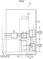
- FIG. 2 schematically illustrates how the components of the power converter (10) according to the embodiment are mounted.
- the power converter (10) uses a four-layer substrate as the circuit substrate (20), on which main components are mounted.
- the diodes (D1 to D6) forming the converter circuit (11) are encapsulated in a single package.
- the package is provided with three terminals (T1 to T3) receiving the input from the three-phase AC power source (30) and two terminals (T1 and T5) outputting the direct current.
- the six switching elements (13a) and six freewheeling diodes (13b) of the inverter circuit (13) are also encapsulated in a single package.
- the components of the inverter circuit (13), such as the switching elements (13a), and the converter circuit (11) are encapsulated in different packages.
- the package encapsulating the inverter circuit (13) has a plurality of terminals for wiring, including terminals (T6, T7) for receiving a direct current.
- the reactor (L) of this embodiment includes a covered electric wire wound around a toroidal core. Therefore, the reactor (L) according to this embodiment can be made smaller than a reactor formed using a so-called EI core. Note that the reactor (L) can be relatively made small because a capacitor with a relatively small capacity is used as the capacitor (12). Downsizing of the reactor (L) allows the reactor (L) to be easily mounted on the circuit board (20). In this embodiment, as shown in FIG. 2 , the capacitor (12) and the reactor (L) are mounted on the same circuit board (20).
- the converter circuit (11) (package), the capacitor (12), the reactor (L), and the inverter circuit (13) (package) are mounted on the circuit board (20) in a two-stage grid.
- FIG. 2 shows virtual lines indicating the stages of a virtual grid for convenience of explanation.
- the converter circuit (11) and the reactor (L) are mounted on the same stage of the grid (see the upper stage of the virtual grid shown in FIG. 2 ).
- the inverter circuit (13) and the capacitor (12) are mounted on a stage different from the stage on which the converter circuit (11) is mounted (see the lower stage of the virtual grid shown in FIG. 2 ).
- the converter circuit (11) and the inverter circuit (13) are adjacent to each other, and the reactor (L) and the capacitor (12) are adjacent to each other.
- the common mode coil (60) and the converter circuit (11) are disposed on the same stage of the grid. This can simplify the pattern of traces from the common mode coil (60) to reactor (L) of the circuit board (20).
- power source lines for the three phases of the AC power source (30) extend from the left side in FIG. 2 , and each of the power source lines is connected to one end of a corresponding one of the three common mode coils (60).
- the other end of each common mode coil (60) is connected to a corresponding one of the terminals (T1 to T3) of the converter circuit (11) via the traces formed on the circuit board (20).
- a positive terminal (here, the terminal (T4)) of the converter circuit (11) used for outputting a DC current is connected to one terminal (T8) of the reactor (L) via the trace formed on the circuit board (20).
- a negative terminal (the terminal (T5)) of the converter circuit (11) used for outputting a DC current is connected to one terminal (T10) of the capacitor (12) via the trace formed on the circuit board (20).
- the other terminal (T11) of the capacitor (12) is connected to the other terminal (T9) of the reactor (L) via the trace formed on the circuit board (20).
- the package including the inverter circuit (13) has terminals (not shown) for outputting the three-phase (U, V, W) alternating current. These terminals are connected to terminals (Tu, Tv, Tw) provided on the circuit board (20) via the traces formed on the circuit board (20). Electric power is supplied to the motor (40) through the terminals (Tu, Tv, Tw) and the motor (40) connected to each other via the wire.
- FIG. 3 illustrates an exemplary arrangement for the radiator (50).
- the radiator (50) includes a body member (51) which makes contact with a cooling object (i.e., the converter circuit (11) and the inverter circuit (13)) and receives heat from the cooling object.
- the body member (51) is made of metal such as aluminum.
- a refrigerant pipe (52) through which the refrigerant flows is fixed to the body member (51).
- the refrigerant pipe (52) forms an integral part of a pipe forming the refrigerant circuit (120) included in the air conditioner (100).
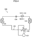
- FIG. 4 illustrates an exemplary configuration for the refrigerant circuit (120).
- the refrigerant circuit (120) is a closed circuit filled with a refrigerant, and the refrigerant circulates in the refrigerant circuit (120) to perform a refrigeration cycle.
- the refrigerant circuit (120) is provided with a compressor (121), a four-way switching valve (122), an outdoor heat exchanger (123), an expansion valve (124), and an indoor heat exchanger (125). Note that the control of the operation of the refrigerant circuit (120) requires a control device, but is not shown in FIG. 4 .
- any one of various compressors can be used as the compressor (121).
- Examples of the compressor (121) include a scroll compressor and a rotary compressor.
- the outdoor heat exchanger (123) and the indoor heat exchanger (125) are so-called “cross-fm type" heat exchangers.
- the outdoor heat exchanger (123) exchanges heat between outdoor air and the refrigerant.
- the indoor heat exchanger (125) exchanges heat between indoor air and the refrigerant.
- the expansion valve (124) is a so-called “electronic expansion valve.”
- the four-way switching valve (122) has first to fourth ports.
- the four-way switching valve (122) is switchable between a first state in which the first port communicates with the third port, and the second port communicates with the fourth port (indicated by solid curves FIG. 4 ), and a second state in which the first port communicates with the fourth port, and the second port communicates with the third port (indicated by broken curves in FIG. 4 ).
- the compressor (121) has discharge and suction ports respectively connected to the first and second ports of the four-way switching valve (122).
- the outdoor heat exchanger (123), the expansion valve (124), and the indoor heat exchanger (125) are arranged in this order from the third port to fourth port of the four-way switching valve (122).
- the air conditioner (100) switches the four-way switching valve (122) to switch between a cooling operation and a heating operation.
- the refrigerant pipe (52) (see FIG. 4 ) connecting the outdoor heat exchanger (123) and the expansion valve (124) together is fixed to the body member (51) of the heat radiator (50). That is to say, the body member (51) dissipates heat to the refrigerant flowing between the outdoor heat exchanger (123) and the expansion valve (124).
- the body member (51) of the radiator (50) is formed in a rectangular shape when viewed in plan.
- the body member (51) is disposed to extend across the cooling objects, namely, the converter circuit (11) and the inverter circuit (13).
- the radiator (50) is disposed between the common mode coil (60) and the reactor (L).
- the capacitor (12) which has been generally implemented by an electrolytic capacitor, is comprised of a film capacitor, and the capacitor (12) and the reactor (L) are mounted on the same circuit substrate (20). Therefore, countermeasures against noise (the addition of a snubber circuit or a ferrite core), which have been required in the prior art in connecting the reactor outside the circuit board and the circuit board to each other via wiring, is no longer necessary. That is to say, this embodiment can arrange the power converter (10) in a smaller layout area.
- the capacitor (12), the reactor (L), and the inverter circuit (13) are mounted on the circuit board (20) in a two-stage grid. This arrangement also contributes to the reduction in the layout area of the power converter (10).
- the four-layer substrate used as the circuit board (20) makes it possible to further downsize the circuit board (20).
- the converter circuit (11) and the inverter circuit (13) may be encapsulated in the same package.
- the power converter (10) (circuit board (20)) can be expected to be further downsized.
- the fixed position of the radiator (50) in the refrigerant circuit (120) is illustrated as an example.
- the refrigerant pipe (52) to be fixed to the body member (51) of the radiator (50) is not limited to the refrigerant pipe connecting the outdoor heat exchanger (123) and the expansion valve (124) together.
- the configuration of the radiator (50) is an example.
- a heat sink for cooling with the air may be used as the radiator (50).
- the present invention is useful as a power converter.
Landscapes
- Engineering & Computer Science (AREA)
- Power Engineering (AREA)
- Physics & Mathematics (AREA)
- Mechanical Engineering (AREA)
- Thermal Sciences (AREA)
- General Engineering & Computer Science (AREA)
- Microelectronics & Electronic Packaging (AREA)
- Inverter Devices (AREA)
- Rectifiers (AREA)
Abstract
Description
- The present invention relates to a power converter.
- An apparatus such as an air conditioner has a power converter to drive a motor. In many cases, a power converter includes, e.g., a converter circuit and an inverter circuit (see, for example, Patent Document 1). Such a power converter is often provided with a reactor at the output of the converter circuit to reduce, e.g., a harmonic current.
- Patent Document 1: Japanese Unexamined Patent Publication No.
2013-224785 - In the example of the above-mentioned patent document, the reactor is not provided on a printed circuit board. Therefore, the reactor needs to be connected to the printed circuit board via wiring, which may require some countermeasures against noise. Specifically, a ferrite core and/or a snubber circuit may sometimes need to be installed. This means that the apparatus of the prior art may increase in cost and size. On the other hand, the reactor is a relatively large component, and cannot be easily mounted on a printed circuit board.
- In view of the foregoing disadvantages, the present invention has been achieved to arrange a power converter including a converter circuit and an inverter circuit in a smaller layout area.
- In order to solve the above problems, a first aspect of the present invention is directed to a power converter including: a converter circuit (11) converting an alternating current to a direct current; a reactor (L) electrically connected to one of output terminals of the converter circuit (11); a capacitor (12) electrically connected to the other output terminal of the converter circuit (11) and the reactor (L); and an inverter circuit (13) electrically connected to the capacitor (12) and converts the direct current to an alternating current, wherein the capacitor (12) is a film capacitor, and the capacitor (12) and the reactor (L) are mounted on an identical circuit board (20).
- In this configuration, use of the film capacitor can downsize the capacitor (12), and as a result, the reactor (L) can be easily mounted on the circuit board (20). Therefore, countermeasures against noise (the addition of a snubber circuit or a ferrite core), which have been required in the prior art in connecting the reactor outside the circuit board and the circuit board to each other via wiring, is no longer necessary.
- A second aspect is an embodiment of the first aspect. In the second aspect, the converter circuit (11), the capacitor (12), the reactor (L), and the inverter circuit (13) are mounted on the circuit board (20) in a two-stage grid, the converter circuit (11) and the reactor (L) are mounted on an identical stage of the grid, the inverter circuit (13) and the capacitor (12) are mounted on a stage different from a stage on which the converter circuit (11) is mounted in the grid, and the converter circuit (11) and the inverter circuit (13) are adjacent to each other, and the reactor (L) and the capacitor (12) are adjacent to each other, in the grid.
- This configuration can simplify the wiring connecting the converter circuit (11), the capacitor (12), the inverter circuit (13), and the reactor (L).
- A third aspect is an embodiment of the first or second aspect. In the third aspect, the capacitor (12) and the reactor (L) form a resonant circuit, whose resonant frequency is set such that a ripple current component included in the direct current outputted from the converter circuit (11) passes through the resonant circuit, and a current component having a same frequency as a carrier frequency of the inverter circuit (13) is attenuated.
- In a power converter using a capacitor having a relatively small capacity as the capacitor (12), this configuration no longer requires countermeasures against noise (the addition of a snubber circuit or a ferrite core), which have been required in the prior art in connecting the reactor outside the circuit board and the circuit board to each other via wiring.
- A fourth aspect is an embodiment of any one of the first to the third aspects. In the fourth aspect, the power converter further includes a radiator (50) which cools the converter circuit (11) and the inverter circuit (13) using a refrigerant flowing through a refrigerant circuit (120) performing a refrigeration cycle.
- This configuration allows the refrigerant in the refrigerant circuit (120) to cool the converter circuit (11) and the inverter circuit (13).
- A fifth aspect is an embodiment of the second aspect. In the fifth aspect, the power converter further includes: a radiator (50) which cools the converter circuit (11) and the inverter circuit (13) using a refrigerant flowing through a refrigerant circuit (120) performing a refrigeration cycle; and a noise filter member (60) disposed to precede the converter circuit (11), wherein the radiator (50) is disposed between the noise filter member (60) and the reactor (L).
- This configuration allows the noise filter member (60) to be disposed on the same stage of the grid on which the converter circuit (11) and the reactor (L) are mounted.
- According to the first aspect, the power converter can be arranged in a smaller layout area.
- Further, the converter circuit, the capacitor, the inverter circuit, and the reactor arranged according to the second aspect can contribute to the reduction in the layout area of the power converter.
- Further, the third aspect can provide a power converter having a capacitor of a relatively small capacity with the above-described advantages.
- Further, the fourth aspect can provide a power converter using a refrigerant to cool a converter circuit and an inverter circuit with the above-described advantages.
- According to the fifth aspect, the pattern of traces from the noise filter member to the reactor can be simplified.
-
- [
FIG. 1] FIG. 1 is a block diagram illustrating an exemplary configuration for a power converter according to an embodiment of the present invention. - [
FIG. 2] FIG. 2 schematically illustrates how components of the power converter according to an embodiment of the present invention are mounted. - [
FIG. 3] FIG. 3 illustrates an exemplary arrangement for a radiator. - [
FIG. 4] FIG. 4 illustrates an exemplary configuration for a refrigerant circuit. - Embodiments of the present invention will be described in detail below with reference to the drawings. The embodiments below are merely exemplary ones in nature, and are not intended to limit the scope, applications, or use of the invention.
- «Embodiment of Invention»
-
FIG. 1 is a block diagram illustrating an exemplary configuration for a power converter (10) according to an embodiment of the present invention. The power converter (10) includes a converter circuit (11), a capacitor (12), a reactor (L), and a control unit (14). A three-phase alternating current (AC) power source (30) (e.g., a commercial three-phase AC power source) is connected to the power converter (10). The power converter (10) converts a current outputted from the AC power source (30) to a three-phase alternating current, and supplies it to a motor (40) that is a load. In this example, the motor (40) is incorporated in a compressor (121) provided for a refrigerant circuit (120) of an air conditioner (100), which will be described later. The motor (40) drives a compression mechanism provided for the compressor (121). In this example, an interior permanent magnet (abbreviated as IPM) motor is employed as the motor (40). - The converter circuit (11) includes six diodes (D1 to D6) bridge-connected to each other, and performs full-wave rectification of the alternating current inputted from the AC power source (30). In this example, the converter circuit (11) is connected to the AC power source (30) via a common mode coil (60). That is to say, the common mode coil (60) is provided to precede the converter circuit (11). The common mode coil (60) is provided to reduce common mode noise, and is an example of a noise filter member of the present invention. The common mode coil (60) of three phases is wound around one ferrite core. That is to say, the common mode coil (60) is shown as three coils on the circuit diagram, but is mounted as a single component on a circuit board (20) which will be described later.
- The capacitor (12) is connected between positive and negative output nodes of the converter circuit (11), and a direct current (DC) voltage generated at both ends of the capacitor (12) is applied to the input node of the inverter circuit (13). As shown in
FIG. 1 , the reactor (L) is disposed between the positive output node of the converter circuit (11) and the capacitor (12). - The capacitor (12) of this embodiment is a film capacitor. The capacitor (12) has an electrostatic capacitance capable of smoothing only a ripple voltage (voltage variation) generated when a switching element (which will be described later) of the inverter circuit (13) performs a switching operation. That is, the capacitor (12) is of a small capacity, and has no electrostatic capacitance which smooths the voltage rectified by the converter circuit (11) (a voltage that varies in accordance with the power source voltage). More specifically, the capacitor (12) and the reactor (L) form a resonant circuit, and its resonant frequency is set, or the electrostatic capacitance of the capacitor (12) and the inductance of the reactor (L) are set, such that a ripple current component included in the direct current outputted from the converter circuit (11) passes through the resonant circuit, and a current component having the same frequency as a carrier signal (carrier frequency) of the inverter circuit (13), which will be described later, is attenuated.
- The inverter circuit (13) changes the switching state (on and off states) of a plurality of switching elements (13a) to convert the direct current outputted from the converter circuit (11) to an alternating current, and supply the alternating current to the motor (40). Specifically, as shown in
FIG. 1 , the inverter circuit (13) includes six switching elements (13a) bridge-connected to each other, and freewheeling diodes (13b) are connected to the respective switching elements (13a). The on and off states of the switching elements (13a) of the inverter circuit (13) are controlled in synchronization with a carrier signal of a predetermined frequency. Specifically, the control unit (14) performs the on and off control of the switching elements (13a). - The control unit (14) includes a microcomputer and a memory device (which may be incorporated in the microcomputer) storing a program for operating the microcomputer. In order to operate the motor (40) in a desired state, the control unit (14) generates a command to the switching elements (13a) (hereinafter referred to as a switching command (G)) and outputs the command to the switching elements (13a). The switching command (G) is a signal for switching each switching element (13a) between the on and off states, and is generated in accordance with, e.g., a deviation between a target rotational speed of the motor (40) and a current rotational speed of the motor (40).
-
FIG. 2 schematically illustrates how the components of the power converter (10) according to the embodiment are mounted. The power converter (10) uses a four-layer substrate as the circuit substrate (20), on which main components are mounted. - In this embodiment, the diodes (D1 to D6) forming the converter circuit (11) are encapsulated in a single package. The package is provided with three terminals (T1 to T3) receiving the input from the three-phase AC power source (30) and two terminals (T1 and T5) outputting the direct current.
- The six switching elements (13a) and six freewheeling diodes (13b) of the inverter circuit (13) are also encapsulated in a single package. In this example, the components of the inverter circuit (13), such as the switching elements (13a), and the converter circuit (11) are encapsulated in different packages. The package encapsulating the inverter circuit (13) has a plurality of terminals for wiring, including terminals (T6, T7) for receiving a direct current.
- Moreover, the reactor (L) of this embodiment includes a covered electric wire wound around a toroidal core. Therefore, the reactor (L) according to this embodiment can be made smaller than a reactor formed using a so-called EI core. Note that the reactor (L) can be relatively made small because a capacitor with a relatively small capacity is used as the capacitor (12). Downsizing of the reactor (L) allows the reactor (L) to be easily mounted on the circuit board (20). In this embodiment, as shown in
FIG. 2 , the capacitor (12) and the reactor (L) are mounted on the same circuit board (20). - Specifically, the converter circuit (11) (package), the capacitor (12), the reactor (L), and the inverter circuit (13) (package) are mounted on the circuit board (20) in a two-stage grid.
FIG. 2 shows virtual lines indicating the stages of a virtual grid for convenience of explanation. The converter circuit (11) and the reactor (L) are mounted on the same stage of the grid (see the upper stage of the virtual grid shown inFIG. 2 ). - The inverter circuit (13) and the capacitor (12) are mounted on a stage different from the stage on which the converter circuit (11) is mounted (see the lower stage of the virtual grid shown in
FIG. 2 ). In the grid, the converter circuit (11) and the inverter circuit (13) are adjacent to each other, and the reactor (L) and the capacitor (12) are adjacent to each other. Further, the common mode coil (60) and the converter circuit (11) are disposed on the same stage of the grid. This can simplify the pattern of traces from the common mode coil (60) to reactor (L) of the circuit board (20). - Regarding the wiring, power source lines for the three phases of the AC power source (30) extend from the left side in
FIG. 2 , and each of the power source lines is connected to one end of a corresponding one of the three common mode coils (60). The other end of each common mode coil (60) is connected to a corresponding one of the terminals (T1 to T3) of the converter circuit (11) via the traces formed on the circuit board (20). A positive terminal (here, the terminal (T4)) of the converter circuit (11) used for outputting a DC current is connected to one terminal (T8) of the reactor (L) via the trace formed on the circuit board (20). Further, a negative terminal (the terminal (T5)) of the converter circuit (11) used for outputting a DC current is connected to one terminal (T10) of the capacitor (12) via the trace formed on the circuit board (20). The other terminal (T11) of the capacitor (12) is connected to the other terminal (T9) of the reactor (L) via the trace formed on the circuit board (20). - The package including the inverter circuit (13) has terminals (not shown) for outputting the three-phase (U, V, W) alternating current. These terminals are connected to terminals (Tu, Tv, Tw) provided on the circuit board (20) via the traces formed on the circuit board (20). Electric power is supplied to the motor (40) through the terminals (Tu, Tv, Tw) and the motor (40) connected to each other via the wire.
- The converter circuit (11) and inverter circuit (13) of the power converter (10) generate heat during operation, and are cooled by the radiator (50).
FIG. 3 illustrates an exemplary arrangement for the radiator (50). The radiator (50) includes a body member (51) which makes contact with a cooling object (i.e., the converter circuit (11) and the inverter circuit (13)) and receives heat from the cooling object. The body member (51) is made of metal such as aluminum. A refrigerant pipe (52) through which the refrigerant flows is fixed to the body member (51). The refrigerant pipe (52) forms an integral part of a pipe forming the refrigerant circuit (120) included in the air conditioner (100). - Here, the refrigerant circuit (120) will be briefly described.
FIG. 4 illustrates an exemplary configuration for the refrigerant circuit (120). The refrigerant circuit (120) is a closed circuit filled with a refrigerant, and the refrigerant circulates in the refrigerant circuit (120) to perform a refrigeration cycle. The refrigerant circuit (120) is provided with a compressor (121), a four-way switching valve (122), an outdoor heat exchanger (123), an expansion valve (124), and an indoor heat exchanger (125). Note that the control of the operation of the refrigerant circuit (120) requires a control device, but is not shown inFIG. 4 . - Any one of various compressors can be used as the compressor (121). Examples of the compressor (121) include a scroll compressor and a rotary compressor. The outdoor heat exchanger (123) and the indoor heat exchanger (125) are so-called "cross-fm type" heat exchangers. The outdoor heat exchanger (123) exchanges heat between outdoor air and the refrigerant. The indoor heat exchanger (125) exchanges heat between indoor air and the refrigerant. The expansion valve (124) is a so-called "electronic expansion valve."
- The four-way switching valve (122) has first to fourth ports. The four-way switching valve (122) is switchable between a first state in which the first port communicates with the third port, and the second port communicates with the fourth port (indicated by solid curves
FIG. 4 ), and a second state in which the first port communicates with the fourth port, and the second port communicates with the third port (indicated by broken curves inFIG. 4 ). - In the refrigerant circuit (120), the compressor (121) has discharge and suction ports respectively connected to the first and second ports of the four-way switching valve (122). In this refrigerant circuit (120), the outdoor heat exchanger (123), the expansion valve (124), and the indoor heat exchanger (125) are arranged in this order from the third port to fourth port of the four-way switching valve (122). The air conditioner (100) switches the four-way switching valve (122) to switch between a cooling operation and a heating operation. In the refrigerant circuit (120), the refrigerant pipe (52) (see
FIG. 4 ) connecting the outdoor heat exchanger (123) and the expansion valve (124) together is fixed to the body member (51) of the heat radiator (50). That is to say, the body member (51) dissipates heat to the refrigerant flowing between the outdoor heat exchanger (123) and the expansion valve (124). - When the components of the power converter (10) such as the converter circuit (11) are arranged on the circuit board (20) as described above, the converter circuit (11) and the inverter circuit (13) are substantially aligned on the same line (see
FIG. 2 ). Therefore, in this example, as shown inFIG. 3 , the body member (51) of the radiator (50) is formed in a rectangular shape when viewed in plan. The body member (51) is disposed to extend across the cooling objects, namely, the converter circuit (11) and the inverter circuit (13). Thus, the radiator (50) is disposed between the common mode coil (60) and the reactor (L). - As described above, in this embodiment, the capacitor (12), which has been generally implemented by an electrolytic capacitor, is comprised of a film capacitor, and the capacitor (12) and the reactor (L) are mounted on the same circuit substrate (20). Therefore, countermeasures against noise (the addition of a snubber circuit or a ferrite core), which have been required in the prior art in connecting the reactor outside the circuit board and the circuit board to each other via wiring, is no longer necessary. That is to say, this embodiment can arrange the power converter (10) in a smaller layout area.
- The capacitor (12), the reactor (L), and the inverter circuit (13) are mounted on the circuit board (20) in a two-stage grid. This arrangement also contributes to the reduction in the layout area of the power converter (10).
- Further, the four-layer substrate used as the circuit board (20) makes it possible to further downsize the circuit board (20).
- The converter circuit (11) and the inverter circuit (13) may be encapsulated in the same package. Thus, the power converter (10) (circuit board (20)) can be expected to be further downsized.
- The fixed position of the radiator (50) in the refrigerant circuit (120) is illustrated as an example. In other words, the refrigerant pipe (52) to be fixed to the body member (51) of the radiator (50) is not limited to the refrigerant pipe connecting the outdoor heat exchanger (123) and the expansion valve (124) together.
- The configuration of the radiator (50) is an example. For example, a heat sink for cooling with the air may be used as the radiator (50).
- The present invention is useful as a power converter.
-
- 10
- Power Converter
- 11
- Converter Circuit
- 12
- Capacitor
- 13
- Inverter Circuit
- 20
- Circuit Board
- 50
- Radiator
- 60
- Common Mode Coil (Noise Filter Member)
- 120
- Refrigerant Circuit
Claims (5)
- A power converter comprising:a converter circuit (11) converting an alternating current to a direct current;a reactor (L) electrically connected to one of output terminals of the converter circuit (11);a capacitor (12) electrically connected to the other output terminal of the converter circuit (11) and the reactor (L); andan inverter circuit (13) electrically connected to the capacitor (12) and converts the direct current to an alternating current, whereinthe capacitor (12) is a film capacitor, andthe capacitor (12) and the reactor (L) are mounted on an identical circuit board (20).
- The power converter of claim 1, wherein
the converter circuit (11), the capacitor (12), the reactor (L), and the inverter circuit (13) are mounted on the circuit board (20) in a two-stage grid,
the converter circuit (11) and the reactor (L) are mounted on an identical stage of the grid,
the inverter circuit (13) and the capacitor (12) are mounted on a stage different from a stage on which the converter circuit (11) is mounted in the grid, and
the converter circuit (11) and the inverter circuit (13) are adjacent to each other, and the reactor (L) and the capacitor (12) are adjacent to each other, in the grid. - The power converter of claim 1 or 2, wherein
the capacitor (12) and the reactor (L) form a resonant circuit, whose resonant frequency is set such that a ripple current component included in the direct current outputted from the converter circuit (11) passes through the resonant circuit, and a current component having a same frequency as a carrier frequency of the inverter circuit (13) is attenuated. - The power converter of any one of claims 1 to 3, further comprising
a radiator (50) which cools the converter circuit (11) and the inverter circuit (13) using a refrigerant flowing through a refrigerant circuit (120) performing a refrigeration cycle. - The power converter of claim 2, further comprising:a radiator (50) which cools the converter circuit (11) and the inverter circuit (13) using a refrigerant flowing through a refrigerant circuit (120) performing a refrigeration cycle; anda noise filter member (60) disposed to precede the converter circuit (11), whereinthe radiator (50) is disposed between the noise filter member (60) and the reactor (L).
Applications Claiming Priority (2)
| Application Number | Priority Date | Filing Date | Title |
|---|---|---|---|
| JP2017039199A JP6828516B2 (en) | 2017-03-02 | 2017-03-02 | Power converter |
| PCT/JP2018/001813 WO2018159153A1 (en) | 2017-03-02 | 2018-01-22 | Power conversion device |
Publications (3)
| Publication Number | Publication Date |
|---|---|
| EP3591829A1 true EP3591829A1 (en) | 2020-01-08 |
| EP3591829A4 EP3591829A4 (en) | 2020-03-04 |
| EP3591829B1 EP3591829B1 (en) | 2021-07-21 |
Family
ID=63370281
Family Applications (1)
| Application Number | Title | Priority Date | Filing Date |
|---|---|---|---|
| EP18761081.1A Revoked EP3591829B1 (en) | 2017-03-02 | 2018-01-22 | Power conversion device |
Country Status (8)
| Country | Link |
|---|---|
| US (1) | US10756647B2 (en) |
| EP (1) | EP3591829B1 (en) |
| JP (1) | JP6828516B2 (en) |
| CN (1) | CN110192337B (en) |
| AU (1) | AU2018226669B2 (en) |
| ES (1) | ES2886221T3 (en) |
| MY (1) | MY195423A (en) |
| WO (1) | WO2018159153A1 (en) |
Families Citing this family (3)
| Publication number | Priority date | Publication date | Assignee | Title |
|---|---|---|---|---|
| JP7130024B2 (en) * | 2020-11-12 | 2022-09-02 | 三菱電機株式会社 | power converter |
| WO2023042253A1 (en) * | 2021-09-14 | 2023-03-23 | 三菱電機株式会社 | Electric power conversion device and refrigeration cycle device |
| CN116202145B (en) * | 2021-12-01 | 2025-12-02 | 佛山市顺德区美的电子科技有限公司 | Electrical control board, outdoor air conditioning unit and air conditioner |
Family Cites Families (35)
| Publication number | Priority date | Publication date | Assignee | Title |
|---|---|---|---|---|
| JPH07327376A (en) * | 1994-05-30 | 1995-12-12 | Tec Corp | Power converter |
| US5905647A (en) * | 1997-01-20 | 1999-05-18 | Kabushiki Kaisha Toshiba | Inverter with incorporated filter circuit and improved component cooling arrangement |
| DE10156694B4 (en) * | 2001-11-17 | 2005-10-13 | Semikron Elektronik Gmbh & Co. Kg | circuitry |
| JP4596866B2 (en) * | 2003-09-09 | 2010-12-15 | パナソニック株式会社 | Motor drive device |
| JP4956020B2 (en) * | 2005-03-02 | 2012-06-20 | パナソニック株式会社 | Lighting unit and discharge lamp |
| JP5091521B2 (en) * | 2007-03-29 | 2012-12-05 | 三菱重工業株式会社 | Integrated electric compressor |
| KR101372533B1 (en) * | 2007-11-20 | 2014-03-11 | 엘지전자 주식회사 | Motor controller of air conditioner |
| EP2110929B1 (en) * | 2008-04-18 | 2018-08-29 | Grundfos Management a/s | Frequency inverter being mounted on a motor |
| JP5002568B2 (en) | 2008-10-29 | 2012-08-15 | 日立オートモティブシステムズ株式会社 | Power converter |
| JP5235820B2 (en) | 2009-08-17 | 2013-07-10 | 株式会社日立産機システム | Power converter |
| CN201789431U (en) * | 2010-08-04 | 2011-04-06 | 苏州西典机电有限公司 | General inverter module |
| WO2012090307A1 (en) | 2010-12-28 | 2012-07-05 | 三菱電機株式会社 | Electrical converter |
| JP5855899B2 (en) * | 2011-10-27 | 2016-02-09 | 日立オートモティブシステムズ株式会社 | DC-DC converter and power converter |
| JP2013194959A (en) * | 2012-03-16 | 2013-09-30 | Daikin Industries Ltd | Refrigeration apparatus |
| JP5472364B2 (en) | 2012-04-20 | 2014-04-16 | ダイキン工業株式会社 | Refrigeration equipment |
| JP5397497B2 (en) * | 2012-04-20 | 2014-01-22 | ダイキン工業株式会社 | Refrigeration equipment |
| JP2014044007A (en) | 2012-08-27 | 2014-03-13 | Toshiba Corp | Outdoor unit of air conditioner |
| JP2014230317A (en) * | 2013-05-20 | 2014-12-08 | ダイキン工業株式会社 | Motor drive device |
| JP5842905B2 (en) * | 2013-12-24 | 2016-01-13 | ダイキン工業株式会社 | Refrigeration equipment |
| JP2015149883A (en) * | 2014-01-09 | 2015-08-20 | 株式会社デンソー | Power conversion device |
| JP5850073B2 (en) * | 2014-03-18 | 2016-02-03 | ダイキン工業株式会社 | Power converter |
| US9510481B2 (en) * | 2014-03-24 | 2016-11-29 | Daikin Industries, Ltd. | Refrigerant jacket and air conditioning apparatus equipped therewith |
| JP6233183B2 (en) | 2014-05-16 | 2017-11-22 | 株式会社デンソー | Power control unit |
| WO2015182507A1 (en) * | 2014-05-30 | 2015-12-03 | 日立工機株式会社 | Power tool |
| JP6179501B2 (en) * | 2014-12-03 | 2017-08-16 | ダイキン工業株式会社 | Power converter |
| EP3273585B1 (en) * | 2015-03-16 | 2023-04-26 | Mitsubishi Electric Corporation | Power circuit device |
| EP3079451B1 (en) * | 2015-04-09 | 2017-08-02 | ABB Schweiz AG | Cooled power conversion assembly |
| JP6516357B2 (en) * | 2015-04-20 | 2019-05-22 | 三菱重工サーマルシステムズ株式会社 | Circuit board for electric power conversion and electric compressor |
| CN107530873B (en) * | 2015-04-24 | 2021-06-29 | 工机控股株式会社 | electrical tools |
| JP6894181B2 (en) * | 2015-06-17 | 2021-06-30 | ダイキン工業株式会社 | Inverter device |
| JP6701637B2 (en) * | 2015-07-21 | 2020-05-27 | ダイキン工業株式会社 | Inverter device |
| CN107960145B (en) * | 2015-08-28 | 2020-11-03 | 松下知识产权经营株式会社 | Motor drive device, and drive device for compressor and refrigerator using same |
| JP6526253B2 (en) * | 2016-02-10 | 2019-06-05 | 三菱電機株式会社 | Power converter and air conditioner |
| US9998054B1 (en) * | 2016-04-21 | 2018-06-12 | Summit Esp, Llc | Electric submersible pump variable speed drive controller |
| JP6844290B2 (en) * | 2017-02-08 | 2021-03-17 | ダイキン工業株式会社 | Outdoor unit of inverter device and heat pump device |
-
2017
- 2017-03-02 JP JP2017039199A patent/JP6828516B2/en active Active
-
2018
- 2018-01-22 US US16/480,144 patent/US10756647B2/en active Active
- 2018-01-22 AU AU2018226669A patent/AU2018226669B2/en active Active
- 2018-01-22 EP EP18761081.1A patent/EP3591829B1/en not_active Revoked
- 2018-01-22 CN CN201880007359.8A patent/CN110192337B/en active Active
- 2018-01-22 WO PCT/JP2018/001813 patent/WO2018159153A1/en not_active Ceased
- 2018-01-22 ES ES18761081T patent/ES2886221T3/en active Active
- 2018-01-22 MY MYPI2019004634A patent/MY195423A/en unknown
Also Published As
| Publication number | Publication date |
|---|---|
| WO2018159153A1 (en) | 2018-09-07 |
| JP6828516B2 (en) | 2021-02-10 |
| ES2886221T3 (en) | 2021-12-16 |
| CN110192337B (en) | 2021-09-07 |
| EP3591829B1 (en) | 2021-07-21 |
| MY195423A (en) | 2023-01-20 |
| US20190341860A1 (en) | 2019-11-07 |
| AU2018226669A1 (en) | 2019-09-05 |
| EP3591829A4 (en) | 2020-03-04 |
| AU2018226669B2 (en) | 2020-09-24 |
| CN110192337A (en) | 2019-08-30 |
| US10756647B2 (en) | 2020-08-25 |
| JP2018148629A (en) | 2018-09-20 |
Similar Documents
| Publication | Publication Date | Title |
|---|---|---|
| EP3327919B1 (en) | Inverter apparatus | |
| JP7162130B2 (en) | Inverter module and electric compressor including this | |
| CN107852093B (en) | Power conversion device | |
| CN105379089B (en) | Counter-flow-preventing device, power-converting device and frozen air regulating device | |
| JP6785727B2 (en) | Outdoor unit of air conditioner and air conditioner | |
| AU2018226669B2 (en) | Power conversion device | |
| CN110268618A (en) | Power board, power unit and cooling device | |
| JP7394196B2 (en) | Electric circuit and refrigeration cycle equipment | |
| CN109155608B (en) | Motor drive device and air conditioner | |
| CN111064321A (en) | Electronic control components and electrical equipment | |
| JP6884007B2 (en) | Power converter and equipment equipped with it | |
| WO2001073933A1 (en) | Single-phase converter, converter and refrigeration cycle device | |
| JP2012124985A (en) | Refrigeration apparatus | |
| CN207150437U (en) | Conversion system for converting DC power into three-phase AC power and motor system including the same | |
| CN108695053A (en) | Equipment with reactor | |
| JP6491761B2 (en) | Power conversion circuit | |
| JP2022159095A (en) | Power conversion device, air conditioner, and refrigerator | |
| JP2007228717A (en) | Inverter device |
Legal Events
| Date | Code | Title | Description |
|---|---|---|---|
| STAA | Information on the status of an ep patent application or granted ep patent |
Free format text: STATUS: THE INTERNATIONAL PUBLICATION HAS BEEN MADE |
|
| PUAI | Public reference made under article 153(3) epc to a published international application that has entered the european phase |
Free format text: ORIGINAL CODE: 0009012 |
|
| STAA | Information on the status of an ep patent application or granted ep patent |
Free format text: STATUS: REQUEST FOR EXAMINATION WAS MADE |
|
| 17P | Request for examination filed |
Effective date: 20190805 |
|
| AK | Designated contracting states |
Kind code of ref document: A1 Designated state(s): AL AT BE BG CH CY CZ DE DK EE ES FI FR GB GR HR HU IE IS IT LI LT LU LV MC MK MT NL NO PL PT RO RS SE SI SK SM TR |
|
| AX | Request for extension of the european patent |
Extension state: BA ME |
|
| A4 | Supplementary search report drawn up and despatched |
Effective date: 20200205 |
|
| RIC1 | Information provided on ipc code assigned before grant |
Ipc: H02M 7/48 20070101ALI20200130BHEP Ipc: H05K 7/14 20060101ALI20200130BHEP Ipc: F24F 1/22 20110101ALI20200130BHEP Ipc: F25B 31/00 20060101ALI20200130BHEP Ipc: F25B 13/00 20060101ALI20200130BHEP Ipc: H02M 7/12 20060101AFI20200130BHEP Ipc: H02M 5/453 20060101ALI20200130BHEP Ipc: H02M 1/14 20060101ALI20200130BHEP Ipc: H02M 7/00 20060101ALI20200130BHEP |
|
| DAV | Request for validation of the european patent (deleted) | ||
| DAX | Request for extension of the european patent (deleted) | ||
| STAA | Information on the status of an ep patent application or granted ep patent |
Free format text: STATUS: EXAMINATION IS IN PROGRESS |
|
| 17Q | First examination report despatched |
Effective date: 20201002 |
|
| GRAP | Despatch of communication of intention to grant a patent |
Free format text: ORIGINAL CODE: EPIDOSNIGR1 |
|
| STAA | Information on the status of an ep patent application or granted ep patent |
Free format text: STATUS: GRANT OF PATENT IS INTENDED |
|
| INTG | Intention to grant announced |
Effective date: 20210318 |
|
| GRAS | Grant fee paid |
Free format text: ORIGINAL CODE: EPIDOSNIGR3 |
|
| GRAA | (expected) grant |
Free format text: ORIGINAL CODE: 0009210 |
|
| STAA | Information on the status of an ep patent application or granted ep patent |
Free format text: STATUS: THE PATENT HAS BEEN GRANTED |
|
| AK | Designated contracting states |
Kind code of ref document: B1 Designated state(s): AL AT BE BG CH CY CZ DE DK EE ES FI FR GB GR HR HU IE IS IT LI LT LU LV MC MK MT NL NO PL PT RO RS SE SI SK SM TR |
|
| REG | Reference to a national code |
Ref country code: GB Ref legal event code: FG4D |
|
| REG | Reference to a national code |
Ref country code: CH Ref legal event code: EP |
|
| REG | Reference to a national code |
Ref country code: DE Ref legal event code: R096 Ref document number: 602018020512 Country of ref document: DE |
|
| REG | Reference to a national code |
Ref country code: AT Ref legal event code: REF Ref document number: 1413534 Country of ref document: AT Kind code of ref document: T Effective date: 20210815 |
|
| REG | Reference to a national code |
Ref country code: IE Ref legal event code: FG4D |
|
| REG | Reference to a national code |
Ref country code: LT Ref legal event code: MG9D |
|
| REG | Reference to a national code |
Ref country code: NL Ref legal event code: MP Effective date: 20210721 |
|
| REG | Reference to a national code |
Ref country code: AT Ref legal event code: MK05 Ref document number: 1413534 Country of ref document: AT Kind code of ref document: T Effective date: 20210721 |
|
| REG | Reference to a national code |
Ref country code: ES Ref legal event code: FG2A Ref document number: 2886221 Country of ref document: ES Kind code of ref document: T3 Effective date: 20211216 |
|
| PG25 | Lapsed in a contracting state [announced via postgrant information from national office to epo] |
Ref country code: PT Free format text: LAPSE BECAUSE OF FAILURE TO SUBMIT A TRANSLATION OF THE DESCRIPTION OR TO PAY THE FEE WITHIN THE PRESCRIBED TIME-LIMIT Effective date: 20211122 Ref country code: NO Free format text: LAPSE BECAUSE OF FAILURE TO SUBMIT A TRANSLATION OF THE DESCRIPTION OR TO PAY THE FEE WITHIN THE PRESCRIBED TIME-LIMIT Effective date: 20211021 Ref country code: NL Free format text: LAPSE BECAUSE OF FAILURE TO SUBMIT A TRANSLATION OF THE DESCRIPTION OR TO PAY THE FEE WITHIN THE PRESCRIBED TIME-LIMIT Effective date: 20210721 Ref country code: LT Free format text: LAPSE BECAUSE OF FAILURE TO SUBMIT A TRANSLATION OF THE DESCRIPTION OR TO PAY THE FEE WITHIN THE PRESCRIBED TIME-LIMIT Effective date: 20210721 Ref country code: AT Free format text: LAPSE BECAUSE OF FAILURE TO SUBMIT A TRANSLATION OF THE DESCRIPTION OR TO PAY THE FEE WITHIN THE PRESCRIBED TIME-LIMIT Effective date: 20210721 Ref country code: BG Free format text: LAPSE BECAUSE OF FAILURE TO SUBMIT A TRANSLATION OF THE DESCRIPTION OR TO PAY THE FEE WITHIN THE PRESCRIBED TIME-LIMIT Effective date: 20211021 Ref country code: RS Free format text: LAPSE BECAUSE OF FAILURE TO SUBMIT A TRANSLATION OF THE DESCRIPTION OR TO PAY THE FEE WITHIN THE PRESCRIBED TIME-LIMIT Effective date: 20210721 Ref country code: SE Free format text: LAPSE BECAUSE OF FAILURE TO SUBMIT A TRANSLATION OF THE DESCRIPTION OR TO PAY THE FEE WITHIN THE PRESCRIBED TIME-LIMIT Effective date: 20210721 Ref country code: HR Free format text: LAPSE BECAUSE OF FAILURE TO SUBMIT A TRANSLATION OF THE DESCRIPTION OR TO PAY THE FEE WITHIN THE PRESCRIBED TIME-LIMIT Effective date: 20210721 Ref country code: FI Free format text: LAPSE BECAUSE OF FAILURE TO SUBMIT A TRANSLATION OF THE DESCRIPTION OR TO PAY THE FEE WITHIN THE PRESCRIBED TIME-LIMIT Effective date: 20210721 |
|
| PG25 | Lapsed in a contracting state [announced via postgrant information from national office to epo] |
Ref country code: PL Free format text: LAPSE BECAUSE OF FAILURE TO SUBMIT A TRANSLATION OF THE DESCRIPTION OR TO PAY THE FEE WITHIN THE PRESCRIBED TIME-LIMIT Effective date: 20210721 Ref country code: LV Free format text: LAPSE BECAUSE OF FAILURE TO SUBMIT A TRANSLATION OF THE DESCRIPTION OR TO PAY THE FEE WITHIN THE PRESCRIBED TIME-LIMIT Effective date: 20210721 Ref country code: GR Free format text: LAPSE BECAUSE OF FAILURE TO SUBMIT A TRANSLATION OF THE DESCRIPTION OR TO PAY THE FEE WITHIN THE PRESCRIBED TIME-LIMIT Effective date: 20211022 |
|
| REG | Reference to a national code |
Ref country code: DE Ref legal event code: R026 Ref document number: 602018020512 Country of ref document: DE |
|
| PG25 | Lapsed in a contracting state [announced via postgrant information from national office to epo] |
Ref country code: DK Free format text: LAPSE BECAUSE OF FAILURE TO SUBMIT A TRANSLATION OF THE DESCRIPTION OR TO PAY THE FEE WITHIN THE PRESCRIBED TIME-LIMIT Effective date: 20210721 |
|
| PLBI | Opposition filed |
Free format text: ORIGINAL CODE: 0009260 |
|
| PLAX | Notice of opposition and request to file observation + time limit sent |
Free format text: ORIGINAL CODE: EPIDOSNOBS2 |
|
| 26 | Opposition filed |
Opponent name: KSB SE & CO. KGAA Effective date: 20220421 |
|
| PG25 | Lapsed in a contracting state [announced via postgrant information from national office to epo] |
Ref country code: SM Free format text: LAPSE BECAUSE OF FAILURE TO SUBMIT A TRANSLATION OF THE DESCRIPTION OR TO PAY THE FEE WITHIN THE PRESCRIBED TIME-LIMIT Effective date: 20210721 Ref country code: SK Free format text: LAPSE BECAUSE OF FAILURE TO SUBMIT A TRANSLATION OF THE DESCRIPTION OR TO PAY THE FEE WITHIN THE PRESCRIBED TIME-LIMIT Effective date: 20210721 Ref country code: RO Free format text: LAPSE BECAUSE OF FAILURE TO SUBMIT A TRANSLATION OF THE DESCRIPTION OR TO PAY THE FEE WITHIN THE PRESCRIBED TIME-LIMIT Effective date: 20210721 Ref country code: EE Free format text: LAPSE BECAUSE OF FAILURE TO SUBMIT A TRANSLATION OF THE DESCRIPTION OR TO PAY THE FEE WITHIN THE PRESCRIBED TIME-LIMIT Effective date: 20210721 Ref country code: CZ Free format text: LAPSE BECAUSE OF FAILURE TO SUBMIT A TRANSLATION OF THE DESCRIPTION OR TO PAY THE FEE WITHIN THE PRESCRIBED TIME-LIMIT Effective date: 20210721 Ref country code: AL Free format text: LAPSE BECAUSE OF FAILURE TO SUBMIT A TRANSLATION OF THE DESCRIPTION OR TO PAY THE FEE WITHIN THE PRESCRIBED TIME-LIMIT Effective date: 20210721 |
|
| PLBB | Reply of patent proprietor to notice(s) of opposition received |
Free format text: ORIGINAL CODE: EPIDOSNOBS3 |
|
| PG25 | Lapsed in a contracting state [announced via postgrant information from national office to epo] |
Ref country code: MC Free format text: LAPSE BECAUSE OF FAILURE TO SUBMIT A TRANSLATION OF THE DESCRIPTION OR TO PAY THE FEE WITHIN THE PRESCRIBED TIME-LIMIT Effective date: 20210721 |
|
| REG | Reference to a national code |
Ref country code: CH Ref legal event code: PL |
|
| REG | Reference to a national code |
Ref country code: BE Ref legal event code: MM Effective date: 20220131 |
|
| PG25 | Lapsed in a contracting state [announced via postgrant information from national office to epo] |
Ref country code: LU Free format text: LAPSE BECAUSE OF NON-PAYMENT OF DUE FEES Effective date: 20220122 |
|
| PG25 | Lapsed in a contracting state [announced via postgrant information from national office to epo] |
Ref country code: BE Free format text: LAPSE BECAUSE OF NON-PAYMENT OF DUE FEES Effective date: 20220131 |
|
| PG25 | Lapsed in a contracting state [announced via postgrant information from national office to epo] |
Ref country code: LI Free format text: LAPSE BECAUSE OF NON-PAYMENT OF DUE FEES Effective date: 20220131 Ref country code: CH Free format text: LAPSE BECAUSE OF NON-PAYMENT OF DUE FEES Effective date: 20220131 |
|
| PG25 | Lapsed in a contracting state [announced via postgrant information from national office to epo] |
Ref country code: IE Free format text: LAPSE BECAUSE OF NON-PAYMENT OF DUE FEES Effective date: 20220122 |
|
| P01 | Opt-out of the competence of the unified patent court (upc) registered |
Effective date: 20230525 |
|
| PG25 | Lapsed in a contracting state [announced via postgrant information from national office to epo] |
Ref country code: MK Free format text: LAPSE BECAUSE OF FAILURE TO SUBMIT A TRANSLATION OF THE DESCRIPTION OR TO PAY THE FEE WITHIN THE PRESCRIBED TIME-LIMIT Effective date: 20210721 Ref country code: CY Free format text: LAPSE BECAUSE OF FAILURE TO SUBMIT A TRANSLATION OF THE DESCRIPTION OR TO PAY THE FEE WITHIN THE PRESCRIBED TIME-LIMIT Effective date: 20210721 |
|
| PG25 | Lapsed in a contracting state [announced via postgrant information from national office to epo] |
Ref country code: HU Free format text: LAPSE BECAUSE OF FAILURE TO SUBMIT A TRANSLATION OF THE DESCRIPTION OR TO PAY THE FEE WITHIN THE PRESCRIBED TIME-LIMIT; INVALID AB INITIO Effective date: 20180122 |
|
| PG25 | Lapsed in a contracting state [announced via postgrant information from national office to epo] |
Ref country code: TR Free format text: LAPSE BECAUSE OF FAILURE TO SUBMIT A TRANSLATION OF THE DESCRIPTION OR TO PAY THE FEE WITHIN THE PRESCRIBED TIME-LIMIT Effective date: 20210721 |
|
| PG25 | Lapsed in a contracting state [announced via postgrant information from national office to epo] |
Ref country code: MT Free format text: LAPSE BECAUSE OF FAILURE TO SUBMIT A TRANSLATION OF THE DESCRIPTION OR TO PAY THE FEE WITHIN THE PRESCRIBED TIME-LIMIT Effective date: 20210721 |
|
| PGFP | Annual fee paid to national office [announced via postgrant information from national office to epo] |
Ref country code: GB Payment date: 20241128 Year of fee payment: 8 |
|
| PGFP | Annual fee paid to national office [announced via postgrant information from national office to epo] |
Ref country code: FR Payment date: 20241209 Year of fee payment: 8 |
|
| REG | Reference to a national code |
Ref country code: CH Ref legal event code: PK Free format text: BERICHTIGUNGEN |
|
| PGFP | Annual fee paid to national office [announced via postgrant information from national office to epo] |
Ref country code: DE Payment date: 20241203 Year of fee payment: 8 |
|
| RAP4 | Party data changed (patent owner data changed or rights of a patent transferred) |
Owner name: DAIKIN INDUSTRIES, LTD. |
|
| RIN2 | Information on inventor provided after grant (corrected) |
Inventor name: ISHIZEKI SHINICHI Inventor name: KOTERA KEITO Inventor name: HIRAOKA NOBUYASU Inventor name: FUJIWARA MASAHIDE |
|
| PGFP | Annual fee paid to national office [announced via postgrant information from national office to epo] |
Ref country code: ES Payment date: 20250204 Year of fee payment: 8 |
|
| PGFP | Annual fee paid to national office [announced via postgrant information from national office to epo] |
Ref country code: IT Payment date: 20241210 Year of fee payment: 8 |
|
| REG | Reference to a national code |
Ref country code: DE Ref legal event code: R064 Ref document number: 602018020512 Country of ref document: DE Ref country code: DE Ref legal event code: R103 Ref document number: 602018020512 Country of ref document: DE |
|
| RDAF | Communication despatched that patent is revoked |
Free format text: ORIGINAL CODE: EPIDOSNREV1 |
|
| RDAG | Patent revoked |
Free format text: ORIGINAL CODE: 0009271 |
|
| STAA | Information on the status of an ep patent application or granted ep patent |
Free format text: STATUS: PATENT REVOKED |
|
| REG | Reference to a national code |
Ref country code: CH Ref legal event code: N12 Free format text: ST27 STATUS EVENT CODE: U-0-0-N10-N12 (AS PROVIDED BY THE NATIONAL OFFICE) Effective date: 20251008 |
|
| 27W | Patent revoked |
Effective date: 20250514 |
|
| GBPR | Gb: patent revoked under art. 102 of the ep convention designating the uk as contracting state |
Effective date: 20250514 |