EP3591808A1 - Permanent magnet (pm) machine - Google Patents
Permanent magnet (pm) machine Download PDFInfo
- Publication number
- EP3591808A1 EP3591808A1 EP19184816.7A EP19184816A EP3591808A1 EP 3591808 A1 EP3591808 A1 EP 3591808A1 EP 19184816 A EP19184816 A EP 19184816A EP 3591808 A1 EP3591808 A1 EP 3591808A1
- Authority
- EP
- European Patent Office
- Prior art keywords
- magnets
- array
- motor
- magnet
- magnetic
- Prior art date
- Legal status (The legal status is an assumption and is not a legal conclusion. Google has not performed a legal analysis and makes no representation as to the accuracy of the status listed.)
- Granted
Links
Images

Classifications
-
- H—ELECTRICITY
- H02—GENERATION; CONVERSION OR DISTRIBUTION OF ELECTRIC POWER
- H02K—DYNAMO-ELECTRIC MACHINES
- H02K1/00—Details of the magnetic circuit
- H02K1/06—Details of the magnetic circuit characterised by the shape, form or construction
- H02K1/22—Rotating parts of the magnetic circuit
- H02K1/27—Rotor cores with permanent magnets
- H02K1/2706—Inner rotors
- H02K1/272—Inner rotors the magnetisation axis of the magnets being perpendicular to the rotor axis
- H02K1/274—Inner rotors the magnetisation axis of the magnets being perpendicular to the rotor axis the rotor consisting of two or more circumferentially positioned magnets
- H02K1/2753—Inner rotors the magnetisation axis of the magnets being perpendicular to the rotor axis the rotor consisting of two or more circumferentially positioned magnets the rotor consisting of magnets or groups of magnets arranged with alternating polarity
- H02K1/278—Surface mounted magnets; Inset magnets
-
- H—ELECTRICITY
- H02—GENERATION; CONVERSION OR DISTRIBUTION OF ELECTRIC POWER
- H02K—DYNAMO-ELECTRIC MACHINES
- H02K1/00—Details of the magnetic circuit
- H02K1/06—Details of the magnetic circuit characterised by the shape, form or construction
- H02K1/22—Rotating parts of the magnetic circuit
- H02K1/27—Rotor cores with permanent magnets
- H02K1/2706—Inner rotors
- H02K1/272—Inner rotors the magnetisation axis of the magnets being perpendicular to the rotor axis
- H02K1/274—Inner rotors the magnetisation axis of the magnets being perpendicular to the rotor axis the rotor consisting of two or more circumferentially positioned magnets
-
- H—ELECTRICITY
- H02—GENERATION; CONVERSION OR DISTRIBUTION OF ELECTRIC POWER
- H02K—DYNAMO-ELECTRIC MACHINES
- H02K1/00—Details of the magnetic circuit
- H02K1/02—Details of the magnetic circuit characterised by the magnetic material
-
- H—ELECTRICITY
- H02—GENERATION; CONVERSION OR DISTRIBUTION OF ELECTRIC POWER
- H02K—DYNAMO-ELECTRIC MACHINES
- H02K15/00—Processes or apparatus specially adapted for manufacturing, assembling, maintaining or repairing of dynamo-electric machines
- H02K15/02—Processes or apparatus specially adapted for manufacturing, assembling, maintaining or repairing of dynamo-electric machines of stator or rotor bodies
- H02K15/03—Processes or apparatus specially adapted for manufacturing, assembling, maintaining or repairing of dynamo-electric machines of stator or rotor bodies having permanent magnets
-
- H—ELECTRICITY
- H02—GENERATION; CONVERSION OR DISTRIBUTION OF ELECTRIC POWER
- H02K—DYNAMO-ELECTRIC MACHINES
- H02K2201/00—Specific aspects not provided for in the other groups of this subclass relating to the magnetic circuits
- H02K2201/06—Magnetic cores, or permanent magnets characterised by their skew
Definitions
- Exemplary embodiments pertain to the art of permanent magnet (PM) machines and more specifically PM machines having a rotor poles comprising an array of permanent magnets.
- PM permanent magnet
- Permanent magnet (PM) machines may consist of one type of permanent magnet located around a circumference of a rotor to constitute magnetic poles.
- the magnets may be located on the surface of the rotor or be embedded inside the rotor.
- the poles may consist of a single piece magnet or be segmented radially and/or axially for loss reduction, manufacturability, reduced cost, etc.
- a motor for a permanent magnet machine comprising a magnetic carrier formed by a body so that the motor comprises a plurality of ends, including a first end and an opposing second end, an outer surface of the magnetic carrier extends between the plurality of ends, and a plurality of magnetic poles including a first magnetic pole and a second magnetic pole, the plurality of magnetic poles disposed on the magnet carrier, extending between the plurality of ends, and being adjacent on the outer surface of the magnet carrier, wherein each of the plurality of poles comprising an array of magnets, each magnet in the array of magnets being a permanent magnet, each array of magnets comprising a plurality of magnets including a first magnet and a second magnet, the plurality of magnets differing from each other in one or more of material and magnetic field strength (MGOe), wherein the first plurality of magnets and the second plurality of magnets are adjacently disposed within the array of magnets.
- MGOe material and magnetic field strength
- the array of magnets forms a rectangular grid.
- the magnets are randomly intermixed in the array of magnets.
- each of the magnets has a rectangular surface area.
- each of the magnets is tapered on opposing diagonal edges and the opposing diagonal edges are aligned along a skew axis, wherein the skew axis is skewed to a long axis for the motor.
- the array of magnets includes a plurality of sets of magnets having homogenous properties, wherein the array of magnets is configured as a mosaic that is symmetrically disposed about a skew axis that is skewed to a long axis of the motor.
- the homogenous magnets are arranged in the mosaic so that the strongest magnets are clustered together and disposed on the skew axis and successively weaker magnets are successively offset.
- the homogenous magnets are arranged in the mosaic so that the strongest magnets are clustered together and disposed on the skew axis and successively weaker magnets are successively layered in an outward direction.
- the motor is a rotary motor
- the magnetic carrier is a rotor
- the plurality of ends are axial ends.
- the array of magnets includes two or more of NdFeB, SmCo, AINiCo and Ferrite.
- a method of configuring a motor for a permanent magnet machine comprising: forming a magnetic carrier that includes by a body including a plurality of ends, including a first end and an opposing second end, an outer surface of the magnetic carrier extending between the plurality of ends, and forming on the magnetic carrier a plurality of magnetic poles including a first magnetic pole and a second magnetic pole, the plurality of magnetic poles extending between the plurality of ends, and being adjacent on the outer surface of the magnet carrier, wherein each of the plurality of poles comprising an array of magnets, each magnet in the array of magnets being a permanent magnet, each array of magnets comprising a plurality of magnets including a first magnet and a second magnet, the plurality of magnets differing from each other in one or more of material and magnetic field strength (MGOe), wherein the first plurality of magnets and the second plurality of magnets are adjacently disposed within the array of magnets.
- MGOe material and magnetic field strength
- the array of magnets may form a rectangular grid.
- the magnets may be randomly intermixed in the array of magnets.
- Each of the magnets may have a rectangular surface area.
- Each of the magnets may be tapered on opposing diagonal edges and the opposing diagonal edges may be aligned along a skew axis, wherein the skew axis is skewed to a long axis for the motor.
- the array of magnets may include a plurality of sets of magnets having homogenous properties, wherein the array of magnets is configured as a mosaic that is symmetrically disposed about a skew axis that is skewed to a long axis of the motor.
- the homogenous magnets may be arranged in the mosaic so that the strongest magnets are clustered together and disposed on the skew axis and successively weaker magnets are successively offset.
- the homogenous magnets may be arranged in the mosaic so that the strongest magnets are clustered together and disposed on the skew axis and successively weaker magnets are successively layered in an outward direction.
- the motor may be a rotary motor, the magnetic carrier may be a rotor and the plurality of ends may be axial ends.
- the array of magnets may include two or more of NdFeB, SmCo, AINiCo and Ferrite.
- the rotor 10 may comprise a magnet carrier 20 formed by a cylindrical body, which may be ferromagnetic. From this configuration the rotor 10 may comprise a plurality of axial ends, including a first axial end 25 and an opposing second axial end 30. An outer surface 35 of the magnetic carrier 20 may extend between the plurality of axial ends.
- the rotor 10 includes a plurality of magnetic poles including a first magnetic pole 40 and a second magnetic pole 45.
- the plurality of magnetic poles may be disposed on the magnet carrier 20 and may extend between the plurality of axial ends. Further, the plurality of poles may be circumferentially adjacent on the radial outer surface 35 of the magnet carrier 20.
- the plurality of poles form sets of poles about the rotor 10 as would be appreciated by one of ordinary skill. As the poles may be similarly applied to the rotor 10, reference hereinafter shall be to magnetic pole 40.
- the magnetic pole 40 may comprise an array of the magnets distributed axially between the axial ends 25 and 30 and circumferentially about the rotor 10. Magnets in single pole may be distributed along a fraction of a circumference of the rotor, wherein the fraction may be inversely proportional to the number of poles of the rotor. For a rotor with two poles, magnets for a first pole on the rotor may span one half (approximately fifty percent) of the circumference of the rotor. For a rotor with six poles, the magnets for a first pole on the rotor may span one sixth (approximate seventeen percent) of the circumference of the rotor.
- the array includes a plurality of magnets including a first magnet 50 and a second magnet 55.
- the magnets may differ from each other in material type and magnetic strength (MGOe).
- the array of magnets may comprise between 30% and 40% variation in MGOe.
- a 35% variation in MGOe may be obtained by a random selection of magnets from a pool of 26MGOe, 28MGOe, 35MGOe and 40MGOe.
- the array of magnets may be configured as a rectangular array or grid over the outer surface 35 of the rotor 10.
- the array of magnets may be configured in a plurality of axially extending rows of magnets including a first row of magnets 64 and a second row of magnets 65.
- the array of magnets may also include a plurality of circumferentially extending columns of magnets, including a first column of magnets 70 and a second column of magnets 75.
- the differing magnets may be randomly intermixed within the array of magnets.
- each of the plurality of magnets may have a rectangular surface area, though other shapes that enable forming the plurality of poles may be within the scope of the disclosure.
- the array of magnets may include two or more of NdFeB, SmCo, AINiCo and Ferrite. In some embodiments the array of magnets may include recycled magnets.
- a plurality of axially extending bosses including a first boss 80 and a second boss 85 may protrude radially outwardly from the radial outer surface 35 of the magnet carrier 20.
- the plurality of axially extending bosses may extend between opposing axial ends of the rotor core 10 to separate adjacent ones of the plurality of poles. In some embodiments instead of having a plurality of bosses the adjacent poles may be separated by corresponding circumferential spaces.
- the plurality of magnets may continuously cover the rotor core 10.
- the plurality of bosses may be ferromagnetic or non-magnetic.
- the plurality of bosses may be wedge shaped or may be a corresponding plurality of grooves in the core 10 enlarging magnetic separation between adjacent ones of the plurality of poles.
- the array may form a first mosaic of magnets that comprises a plurality of sets of magnets, wherein within each set of magnets has homogenous properties.
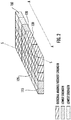
- the sets of magnets may include, for example, a first set distributed over first and second circumferentially outer portions 110, 115, a second set distributed over third and fourth circumferential intermediate portions 120, 125 and a third set distributed over a center fifth portion 130.
- the first set of magnets distributed over circumferential portions 110, 115 has a weaker magnetic strength than the second set distributed over circumferential portions 120, 125, which in turn has a weaker magnetic strength than the third set distributed over circumferential portion 130.
- the magnets may be randomly intermixed ( FIG. 1 ), the sets of magnets may be configured in specific mosaics to provide specific results. That is, a typical motor may use magnets with uniform properties, and in the disclosed embodiments pole fields may be shaped by using magnets of various types and/or strengths in one or more sections of a pole. The disclosed take advantage of the fact that different types of magnets may have the same strength (MGOe) and yet may differ with respect to other parameters such as remanence or coercivity.
- MGOe strength
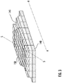
- the sets of magnets may be configured in mosaics that are skewed to the long axis A-A of the rotor 10 and/or configured in a tapered arrangement, where the tapering may be according to magnetic strength and number of magnets.
- the mosaics may be symmetric about a skew axis S-S. Such mosaics and variations thereof may offset torque ripples induced by using different types of magnets.
- the sets are provided in a first mosaic on the outer surface 35 of the rotor 10.
- each of the sets are axially skewed from long axis A-A and are symmetric about skew axis S-S.
- the first set of magnets 10 may be disposed in the center of the mosaic, the second set of magnets may be is divided outside of the first set, and the third set of magnets may be divided outside the second set.
- the first mosaic may include more magnets from the first set than the second set, and more magnets from the second set than the third set.
- FIG. 3 illustrates a second mosaic on the outer surface 35 of the rotor 10.
- the sets of magnets are layered so that the first set 100 is bottom layer, the second set is a middle layer 145 and the third set is a top layer.
- the top layer 150 and the middle layer 145 are skewed from the long axis A-A and centered about a skew axis S-S.
- the bottom layer 150 is illustrated as being rectangular and aligned with the long axis of the rotor 10 and having a diagonal along the skew axis S-S so that the second mosaic is also symmetric about the skew axis S-S.
- the second mosaic may also include more magnets from the first set than the second set, and more magnets from the second set than the third set.
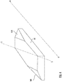
- a magnet such as the first magnet 50, may be tapered on opposing diagonal edges, including first edge 155 and second edge 160. Further, the diagonal edges are disposed on a skew axis S-S that is skewed from the long axis A-A for the rotor 10. The edge tapering of certain ones of the plurality of magnets and axially aligning as indicated may provide an effect similar to that in FIGS. 2 and 3 .
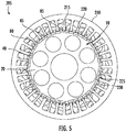
- a PM machine 205 may comprise the rotor 10 disclosed above.
- the rotor 10 may include the magnet carrier 20, the first magnetic pole 40, the second magnetic pole 45, the first boss 80 and the second boss 85.
- the PM machine 205 may include a stator 210 radially outside of the rotor core 10.
- the stator 210 may comprise a plurality of circumferentially spaced teeth including a first tooth 215 and a second tooth 220.
- the plurality of teeth may extend radially inwardly and a plurality of slots including a first slot 225 and a second slot 230 may be formed between the plurality of teeth.
- the plurality of slots may be skewed circumferentially between the opposing axial ends.
- the benefit of skewing the slots, as with providing a skewed configuration to the magnets on the outer surface 35 of the rotor core 10, may be offsetting torque ripples induced by the use of permanent magnets.
- the disclosed architecture may allow utilization of various strength magnets (different MGOe or energy product) that may be sourced from permanent magnets, for example during a recycling process.
- the disclosed embodiments may utilize magnets, newly manufactured or recycled, and if recycled, with minimum rework required limited for cutting magnets to shape.
- PM permanent magnet
- magnets may be clustered and bonded together.
- the disclosed embodiments may be applied to interior PM machines with individual pole configurations that enable sectioning of the magnets.
- the disclosed embodiments may allow for a reduction of cost. For example, cost reduction may be achieved by using recycled magnets, and/or using magnets with various properties, including but not limited to a combination of two or more of NdFeB, SmCo, AlNiCo, Ferrite, etc.
- the disclosed embodiments may result in reducing an environmental impact due to ease of manufacturing as well as an ability to use recycled magnets. It is to be appreciated that the above disclosure may apply to linear motors as well as rotary motors.
Landscapes
- Engineering & Computer Science (AREA)
- Power Engineering (AREA)
- Manufacturing & Machinery (AREA)
- Permanent Field Magnets Of Synchronous Machinery (AREA)
Abstract
Description
- Exemplary embodiments pertain to the art of permanent magnet (PM) machines and more specifically PM machines having a rotor poles comprising an array of permanent magnets.
- Permanent magnet (PM) machines may consist of one type of permanent magnet located around a circumference of a rotor to constitute magnetic poles. The magnets may be located on the surface of the rotor or be embedded inside the rotor. The poles may consist of a single piece magnet or be segmented radially and/or axially for loss reduction, manufacturability, reduced cost, etc.
- Disclosed is a motor for a permanent magnet machine, the motor comprising a magnetic carrier formed by a body so that the motor comprises a plurality of ends, including a first end and an opposing second end, an outer surface of the magnetic carrier extends between the plurality of ends, and a plurality of magnetic poles including a first magnetic pole and a second magnetic pole, the plurality of magnetic poles disposed on the magnet carrier, extending between the plurality of ends, and being adjacent on the outer surface of the magnet carrier, wherein each of the plurality of poles comprising an array of magnets, each magnet in the array of magnets being a permanent magnet, each array of magnets comprising a plurality of magnets including a first magnet and a second magnet, the plurality of magnets differing from each other in one or more of material and magnetic field strength (MGOe), wherein the first plurality of magnets and the second plurality of magnets are adjacently disposed within the array of magnets.
- In some embodiments, the array of magnets forms a rectangular grid.
- In some embodiments, the magnets are randomly intermixed in the array of magnets.
- In some embodiments, each of the magnets has a rectangular surface area.
- In some embodiments, each of the magnets is tapered on opposing diagonal edges and the opposing diagonal edges are aligned along a skew axis, wherein the skew axis is skewed to a long axis for the motor.
- In some embodiments, the array of magnets includes a plurality of sets of magnets having homogenous properties, wherein the array of magnets is configured as a mosaic that is symmetrically disposed about a skew axis that is skewed to a long axis of the motor.
- In some embodiments, the homogenous magnets are arranged in the mosaic so that the strongest magnets are clustered together and disposed on the skew axis and successively weaker magnets are successively offset.
- In some embodiments, the homogenous magnets are arranged in the mosaic so that the strongest magnets are clustered together and disposed on the skew axis and successively weaker magnets are successively layered in an outward direction.
- In some embodiments, the motor is a rotary motor, the magnetic carrier is a rotor and the plurality of ends are axial ends.
- In some embodiments, the array of magnets includes two or more of NdFeB, SmCo, AINiCo and Ferrite.
- Further disclosed is a method of configuring a motor for a permanent magnet machine, the comprising one or more of the above disclosed features and elements.
- Further disclosed is a method of configuring a motor for a permanent magnet machine, the method comprising: forming a magnetic carrier that includes by a body including a plurality of ends, including a first end and an opposing second end, an outer surface of the magnetic carrier extending between the plurality of ends, and forming on the magnetic carrier a plurality of magnetic poles including a first magnetic pole and a second magnetic pole, the plurality of magnetic poles extending between the plurality of ends, and being adjacent on the outer surface of the magnet carrier, wherein each of the plurality of poles comprising an array of magnets, each magnet in the array of magnets being a permanent magnet, each array of magnets comprising a plurality of magnets including a first magnet and a second magnet, the plurality of magnets differing from each other in one or more of material and magnetic field strength (MGOe), wherein the first plurality of magnets and the second plurality of magnets are adjacently disposed within the array of magnets.
- The array of magnets may form a rectangular grid. The magnets may be randomly intermixed in the array of magnets. Each of the magnets may have a rectangular surface area. Each of the magnets may be tapered on opposing diagonal edges and the opposing diagonal edges may be aligned along a skew axis, wherein the skew axis is skewed to a long axis for the motor. The array of magnets may include a plurality of sets of magnets having homogenous properties, wherein the array of magnets is configured as a mosaic that is symmetrically disposed about a skew axis that is skewed to a long axis of the motor. The homogenous magnets may be arranged in the mosaic so that the strongest magnets are clustered together and disposed on the skew axis and successively weaker magnets are successively offset. The homogenous magnets may be arranged in the mosaic so that the strongest magnets are clustered together and disposed on the skew axis and successively weaker magnets are successively layered in an outward direction. The motor may be a rotary motor, the magnetic carrier may be a rotor and the plurality of ends may be axial ends. The array of magnets may include two or more of NdFeB, SmCo, AINiCo and Ferrite.
- The following descriptions should not be considered limiting in any way. With reference to the accompanying drawings, like elements are numbered alike:
-
FIG. 1 illustrates a rotor according to a disclosed embodiment; and -
FIG. 2 illustrates a permanent magnet applied to the rotor according to a disclosed embodiment; -
FIG. 3 illustrates a skewed array of permanent magnets applied to the rotor according to a disclosed embodiment; -
FIG. 4 illustrates a permanent magnet applied to the rotor according to a disclosed embodiment; and -
FIG. 5 illustrates a machine according to an embodiment. - A detailed description of one or more embodiments of the disclosed apparatus and method are presented herein by way of exemplification and not limitation with reference to the Figures.
- Turning to
FIG. 1 disclosed is arotor 10 for a motor. Therotor 10 may comprise amagnet carrier 20 formed by a cylindrical body, which may be ferromagnetic. From this configuration therotor 10 may comprise a plurality of axial ends, including a firstaxial end 25 and an opposing secondaxial end 30. Anouter surface 35 of themagnetic carrier 20 may extend between the plurality of axial ends. - The
rotor 10 includes a plurality of magnetic poles including a firstmagnetic pole 40 and a secondmagnetic pole 45. The plurality of magnetic poles may be disposed on themagnet carrier 20 and may extend between the plurality of axial ends. Further, the plurality of poles may be circumferentially adjacent on the radialouter surface 35 of themagnet carrier 20. The plurality of poles form sets of poles about therotor 10 as would be appreciated by one of ordinary skill. As the poles may be similarly applied to therotor 10, reference hereinafter shall be tomagnetic pole 40. - As illustrated in
FIG. 1 , themagnetic pole 40 may comprise an array of the magnets distributed axially between theaxial ends rotor 10. Magnets in single pole may be distributed along a fraction of a circumference of the rotor, wherein the fraction may be inversely proportional to the number of poles of the rotor. For a rotor with two poles, magnets for a first pole on the rotor may span one half (approximately fifty percent) of the circumference of the rotor. For a rotor with six poles, the magnets for a first pole on the rotor may span one sixth (approximate seventeen percent) of the circumference of the rotor. - The array includes a plurality of magnets including a
first magnet 50 and asecond magnet 55. The magnets may differ from each other in material type and magnetic strength (MGOe). In one embodiment the array of magnets may comprise between 30% and 40% variation in MGOe. In one embodiment a 35% variation in MGOe may be obtained by a random selection of magnets from a pool of 26MGOe, 28MGOe, 35MGOe and 40MGOe. These are exemplary values and one of ordinary skill would recognize that percentile variations and/or a various numbers and type of permanent magnets are within the scope of the disclosure. - The array of magnets may be configured as a rectangular array or grid over the
outer surface 35 of therotor 10. For example, the array of magnets may be configured in a plurality of axially extending rows of magnets including a first row ofmagnets 64 and a second row ofmagnets 65. The array of magnets may also include a plurality of circumferentially extending columns of magnets, including a first column ofmagnets 70 and a second column ofmagnets 75. In an embodiment the differing magnets may be randomly intermixed within the array of magnets. According to an embodiment each of the plurality of magnets may have a rectangular surface area, though other shapes that enable forming the plurality of poles may be within the scope of the disclosure. - In some embodiments the array of magnets may include two or more of NdFeB, SmCo, AINiCo and Ferrite. In some embodiments the array of magnets may include recycled magnets.
- A plurality of axially extending bosses including a
first boss 80 and asecond boss 85 may protrude radially outwardly from the radialouter surface 35 of themagnet carrier 20. The plurality of axially extending bosses may extend between opposing axial ends of therotor core 10 to separate adjacent ones of the plurality of poles. In some embodiments instead of having a plurality of bosses the adjacent poles may be separated by corresponding circumferential spaces. In some embodiments the plurality of magnets may continuously cover therotor core 10. In some embodiments the plurality of bosses may be ferromagnetic or non-magnetic. In some embodiments the plurality of bosses may be wedge shaped or may be a corresponding plurality of grooves in the core 10 enlarging magnetic separation between adjacent ones of the plurality of poles. - Turning to
FIG. 2 , the array may form a first mosaic of magnets that comprises a plurality of sets of magnets, wherein within each set of magnets has homogenous properties. The sets of magnets may include, for example, a first set distributed over first and second circumferentiallyouter portions 110, 115, a second set distributed over third and fourth circumferentialintermediate portions fifth portion 130. The first set of magnets distributed overcircumferential portions 110, 115 has a weaker magnetic strength than the second set distributed overcircumferential portions circumferential portion 130. - While it has been disclosed that the magnets may be randomly intermixed (
FIG. 1 ), the sets of magnets may be configured in specific mosaics to provide specific results. That is, a typical motor may use magnets with uniform properties, and in the disclosed embodiments pole fields may be shaped by using magnets of various types and/or strengths in one or more sections of a pole. The disclosed take advantage of the fact that different types of magnets may have the same strength (MGOe) and yet may differ with respect to other parameters such as remanence or coercivity. - However, as illustrated in
FIGS. 2 and3 , the sets of magnets may be configured in mosaics that are skewed to the long axis A-A of therotor 10 and/or configured in a tapered arrangement, where the tapering may be according to magnetic strength and number of magnets. In addition, the mosaics may be symmetric about a skew axis S-S. Such mosaics and variations thereof may offset torque ripples induced by using different types of magnets. -
FIG. 2 , for example, the sets are provided in a first mosaic on theouter surface 35 of therotor 10. In the first mosaic each of the sets are axially skewed from long axis A-A and are symmetric about skew axis S-S. The first set ofmagnets 10 may be disposed in the center of the mosaic, the second set of magnets may be is divided outside of the first set, and the third set of magnets may be divided outside the second set. In addition, the first mosaic may include more magnets from the first set than the second set, and more magnets from the second set than the third set. - Further,
FIG. 3 illustrates a second mosaic on theouter surface 35 of therotor 10. In the second mosaic, the sets of magnets are layered so that thefirst set 100 is bottom layer, the second set is amiddle layer 145 and the third set is a top layer. Further, thetop layer 150 and themiddle layer 145 are skewed from the long axis A-A and centered about a skew axis S-S. Thebottom layer 150 is illustrated as being rectangular and aligned with the long axis of therotor 10 and having a diagonal along the skew axis S-S so that the second mosaic is also symmetric about the skew axis S-S. In addition, the second mosaic may also include more magnets from the first set than the second set, and more magnets from the second set than the third set. - Turning to
FIG. 4 , a magnet, such as thefirst magnet 50, may be tapered on opposing diagonal edges, includingfirst edge 155 andsecond edge 160. Further, the diagonal edges are disposed on a skew axis S-S that is skewed from the long axis A-A for therotor 10. The edge tapering of certain ones of the plurality of magnets and axially aligning as indicated may provide an effect similar to that inFIGS. 2 and3 . - The above configurations illustrated in
FIGS. 2-4 , as indicated, may result in a reduction in torque ripples. These configurations, however, are not intended to be limiting. - As illustrated in
FIG. 5 , aPM machine 205 is disclosed that may comprise therotor 10 disclosed above. As disclosed therotor 10 may include themagnet carrier 20, the firstmagnetic pole 40, the secondmagnetic pole 45, thefirst boss 80 and thesecond boss 85. In addition, thePM machine 205 may include astator 210 radially outside of therotor core 10. Thestator 210 may comprise a plurality of circumferentially spaced teeth including afirst tooth 215 and asecond tooth 220. The plurality of teeth may extend radially inwardly and a plurality of slots including afirst slot 225 and asecond slot 230 may be formed between the plurality of teeth. In one embodiment the plurality of slots may be skewed circumferentially between the opposing axial ends. The benefit of skewing the slots, as with providing a skewed configuration to the magnets on theouter surface 35 of therotor core 10, may be offsetting torque ripples induced by the use of permanent magnets. - The disclosed architecture may allow utilization of various strength magnets (different MGOe or energy product) that may be sourced from permanent magnets, for example during a recycling process. The disclosed embodiments may utilize magnets, newly manufactured or recycled, and if recycled, with minimum rework required limited for cutting magnets to shape. For permanent magnet (PM) machines with poles comprising a relatively high number of magnets, random placement of different strength magnets may create a mosaic with a preferred range of averaged strength properties. While a mosaic of various magnets may contribute to small increase of torque ripples, such may be addressed by other means such as the disclosed stator skew. For easier manufacturing, magnets may be clustered and bonded together. The disclosed embodiments may be applied to interior PM machines with individual pole configurations that enable sectioning of the magnets.
- The disclosed embodiments may allow for a reduction of cost. For example, cost reduction may be achieved by using recycled magnets, and/or using magnets with various properties, including but not limited to a combination of two or more of NdFeB, SmCo, AlNiCo, Ferrite, etc. The disclosed embodiments may result in reducing an environmental impact due to ease of manufacturing as well as an ability to use recycled magnets. It is to be appreciated that the above disclosure may apply to linear motors as well as rotary motors.
- The term "about" is intended to include the degree of error associated with measurement of the particular quantity based upon the equipment available at the time of filing the application.
- The terminology used herein is for the purpose of describing particular embodiments only and is not intended to be limiting of the present disclosure. As used herein, the singular forms "a", "an" and "the" are intended to include the plural forms as well, unless the context clearly indicates otherwise. It will be further understood that the terms "comprises" and/or "comprising," when used in this specification, specify the presence of stated features, integers, steps, operations, elements, and/or components, but do not preclude the presence or addition of one or more other features, integers, steps, operations, element components, and/or groups thereof.
- While the present disclosure has been described with reference to an exemplary embodiment or embodiments, it will be understood by those skilled in the art that various changes may be made and equivalents may be substituted for elements thereof without departing from the scope of the present disclosure. In addition, many modifications may be made to adapt a particular situation or material to the teachings of the present disclosure without departing from the essential scope thereof. Therefore, it is intended that the present disclosure not be limited to the particular embodiment disclosed as the best mode contemplated for carrying out this present disclosure, but that the present disclosure will include all embodiments falling within the scope of the claims.
Claims (15)
- A motor for a permanent magnet machine, the motor comprising
a magnetic carrier formed by a body so that the motor comprises a plurality of ends, including a first end and an opposing second end, an outer surface of the magnetic carrier extends between the plurality of ends, and
a plurality of magnetic poles including a first magnetic pole and a second magnetic pole, the plurality of magnetic poles disposed on the magnet carrier, extending between the plurality of ends, and being adjacent on the outer surface of the magnet carrier,
wherein
each of the plurality of poles comprising an array of magnets, each magnet in the array of magnets being a permanent magnet,
each array of magnets comprising a plurality of magnets including a first magnet and a second magnet, the plurality of magnets differing from each other in one or more of material and magnetic field strength (MGOe), wherein the first plurality of magnets and the second plurality of magnets are adjacently disposed within the array of magnets. - The motor of claim 1 wherein the array of magnets forms a rectangular grid.
- The motor of claim 2 wherein the magnets are randomly intermixed in the array of magnets.
- The motor of claim 3 wherein each of the magnets has a rectangular surface area.
- The motor of claim 4 wherein each of the magnets is tapered on opposing diagonal edges and the opposing diagonal edges are aligned along a skew axis, wherein the skew axis is skewed to a long axis for the motor.
- The motor of claim 2 wherein the array of magnets includes a plurality of sets of magnets having homogenous properties, wherein the array of magnets is configured as a mosaic that is symmetrically disposed about a skew axis that is skewed to a long axis of the motor.
- The motor of claim 6 wherein the homogenous magnets are arranged in the mosaic so that the strongest magnets are clustered together and disposed on the skew axis and successively weaker magnets are successively offset.
- The motor of claim 6 wherein the homogenous magnets are arranged in the mosaic so that the strongest magnets are clustered together and disposed on the skew axis and successively weaker magnets are successively layered in an outward direction.
- The motor of any preceding claim wherein the motor is a rotary motor, the magnetic carrier is a rotor and the plurality of ends are axial ends.
- The rotor of any preceding claim wherein the array of magnets includes two or more of NdFeB, SmCo, AlNiCo and Ferrite.
- A method of configuring a motor for a permanent magnet machine, the method comprising:forming a magnetic carrier that includes by a body including a plurality of ends, including a first end and an opposing second end, an outer surface of the magnetic carrier extending between the plurality of ends, andforming on the magnetic carrier a plurality of magnetic poles including a first magnetic pole and a second magnetic pole, the plurality of magnetic poles extending between the plurality of ends, and being adjacent on the outer surface of the magnet carrier,whereineach of the plurality of poles comprising an array of magnets, each magnet in the array of magnets being a permanent magnet,each array of magnets comprising a plurality of magnets including a first magnet and a second magnet, the plurality of magnets differing from each other in one or more of material and magnetic field strength (MGOe), wherein the first plurality of magnets and the second plurality of magnets are adjacently disposed within the array of magnets.
- The method of claim 11 wherein the array of magnets forms a rectangular grid.
- The method of claim 12 wherein the magnets are randomly intermixed in the array of magnets.
- The method of claim 13 wherein each of the magnets has a rectangular surface area.
- The method of claim 14 wherein each of the magnets is tapered on opposing diagonal edges and the opposing diagonal edges are aligned along a skew axis, wherein the skew axis is skewed to a long axis for the motor.
Applications Claiming Priority (1)
| Application Number | Priority Date | Filing Date | Title |
|---|---|---|---|
| US16/029,221 US10965177B2 (en) | 2018-07-06 | 2018-07-06 | Permanent magnet (PM) machine having rotor poles with an array of permanent magnets |
Publications (2)
| Publication Number | Publication Date |
|---|---|
| EP3591808A1 true EP3591808A1 (en) | 2020-01-08 |
| EP3591808B1 EP3591808B1 (en) | 2022-08-31 |
Family
ID=67184944
Family Applications (1)
| Application Number | Title | Priority Date | Filing Date |
|---|---|---|---|
| EP19184816.7A Active EP3591808B1 (en) | 2018-07-06 | 2019-07-05 | Permanent magnet (pm) machine |
Country Status (3)
| Country | Link |
|---|---|
| US (1) | US10965177B2 (en) |
| EP (1) | EP3591808B1 (en) |
| CN (1) | CN110690776B (en) |
Families Citing this family (2)
| Publication number | Priority date | Publication date | Assignee | Title |
|---|---|---|---|---|
| CN114629256A (en) * | 2020-11-26 | 2022-06-14 | 通用汽车环球科技运作有限责任公司 | Bi-material permanent magnet for an electric machine |
| CN121124416A (en) * | 2024-06-07 | 2025-12-12 | 奥的斯电梯公司 | Elevator system, permanent magnet motor used therein, and method for manufacturing permanent magnet motor |
Citations (6)
| Publication number | Priority date | Publication date | Assignee | Title |
|---|---|---|---|---|
| EP1816725A1 (en) * | 2006-02-03 | 2007-08-08 | University of Teheran | Permanent magnet assembly for electric machines and actuators, method for their design and electric machines and actuators |
| EP2149965A1 (en) * | 2008-08-01 | 2010-02-03 | Siemens Aktiengesellschaft | Rotor of a synchronous machine with permanent magnets |
| EP2479872A1 (en) * | 2011-01-25 | 2012-07-25 | Siemens Aktiengesellschaft | Permanently excited synchronous machine with a rotor |
| US20120262019A1 (en) * | 2011-04-13 | 2012-10-18 | Boulder Wind Power,Inc. | Flux focusing arrangement for permanent magnets, methods of fabricating such arrangements, and machines including such arrangements |
| WO2014102751A2 (en) * | 2012-12-28 | 2014-07-03 | Wilic S.Ar.L. | Electric machine |
| EP2897265A1 (en) * | 2014-01-15 | 2015-07-22 | Siemens Aktiengesellschaft | Rotor with a assembly of permanent magnets arranged in axial direction and electric machine comprising such a rotor |
Family Cites Families (18)
| Publication number | Priority date | Publication date | Assignee | Title |
|---|---|---|---|---|
| US6411002B1 (en) | 1996-12-11 | 2002-06-25 | Smith Technology Development | Axial field electric machine |
| JPH11103546A (en) | 1997-09-29 | 1999-04-13 | Fujitsu General Ltd | Permanent magnet motor |
| US6700288B2 (en) | 2001-08-15 | 2004-03-02 | Drs Power & Control Technologies, Inc. | High speed rotor |
| AU2002240110B2 (en) | 2002-01-25 | 2007-08-09 | Moog Inc. | Bearing surface layer for magnetic motor |
| US7057323B2 (en) | 2003-03-27 | 2006-06-06 | Emerson Electric Co. | Modular flux controllable permanent magnet dynamoelectric machine |
| JP4214998B2 (en) | 2003-04-11 | 2009-01-28 | 三菱電機株式会社 | Permanent magnet motor |
| KR100680201B1 (en) | 2004-09-17 | 2007-02-08 | 엘지전자 주식회사 | Permanent Magnet Motor |
| US7436095B2 (en) | 2005-10-31 | 2008-10-14 | Caterpillar Inc. | Rotary electric machine |
| US20100171386A1 (en) | 2007-05-28 | 2010-07-08 | Toyota Jidosha Kabushiki Kaisha | Rotor for magnet-embedded motor and magnet-embedded motor |
| JP5433198B2 (en) | 2008-10-16 | 2014-03-05 | 日立オートモティブシステムズ株式会社 | Rotating electric machines and electric vehicles |
| KR101732636B1 (en) * | 2010-08-23 | 2017-05-24 | 주식회사 코베리 | Linear motor |
| US20130169097A1 (en) | 2011-12-31 | 2013-07-04 | Danotek Motion Technologies, Inc. | Low axial force permanent magnet machine |
| EP2704294A1 (en) | 2012-09-03 | 2014-03-05 | Siemens Aktiengesellschaft | Rotor of a permanently excited synchronous machine |
| US9287742B2 (en) | 2013-08-05 | 2016-03-15 | General Electric Company | Spoke permanent magnet machine with reduced torque ripple and method of manufacturing thereof |
| WO2016028471A1 (en) | 2014-08-20 | 2016-02-25 | Moog Inc. | Linear tubular motor magnetic shaft sleeve |
| CN104578499A (en) | 2015-01-29 | 2015-04-29 | 南车株洲电力机车研究所有限公司 | Permanent magnet motor rotor |
| KR102456478B1 (en) | 2015-05-27 | 2022-10-19 | 엘지이노텍 주식회사 | Rotor assembly and Motor using the same |
| CN205081594U (en) | 2015-11-03 | 2016-03-09 | 中科盛创(青岛)电气股份有限公司 | Permanent -magnet machine V shape is rotor structure of utmost point to one side |
-
2018
- 2018-07-06 US US16/029,221 patent/US10965177B2/en not_active Expired - Fee Related
-
2019
- 2019-07-05 EP EP19184816.7A patent/EP3591808B1/en active Active
- 2019-07-05 CN CN201910603861.1A patent/CN110690776B/en not_active Expired - Fee Related
Patent Citations (6)
| Publication number | Priority date | Publication date | Assignee | Title |
|---|---|---|---|---|
| EP1816725A1 (en) * | 2006-02-03 | 2007-08-08 | University of Teheran | Permanent magnet assembly for electric machines and actuators, method for their design and electric machines and actuators |
| EP2149965A1 (en) * | 2008-08-01 | 2010-02-03 | Siemens Aktiengesellschaft | Rotor of a synchronous machine with permanent magnets |
| EP2479872A1 (en) * | 2011-01-25 | 2012-07-25 | Siemens Aktiengesellschaft | Permanently excited synchronous machine with a rotor |
| US20120262019A1 (en) * | 2011-04-13 | 2012-10-18 | Boulder Wind Power,Inc. | Flux focusing arrangement for permanent magnets, methods of fabricating such arrangements, and machines including such arrangements |
| WO2014102751A2 (en) * | 2012-12-28 | 2014-07-03 | Wilic S.Ar.L. | Electric machine |
| EP2897265A1 (en) * | 2014-01-15 | 2015-07-22 | Siemens Aktiengesellschaft | Rotor with a assembly of permanent magnets arranged in axial direction and electric machine comprising such a rotor |
Also Published As
| Publication number | Publication date |
|---|---|
| CN110690776A (en) | 2020-01-14 |
| US10965177B2 (en) | 2021-03-30 |
| US20200014261A1 (en) | 2020-01-09 |
| CN110690776B (en) | 2022-02-18 |
| EP3591808B1 (en) | 2022-08-31 |
Similar Documents
| Publication | Publication Date | Title |
|---|---|---|
| US7830057B2 (en) | Transverse flux machine | |
| US10658893B2 (en) | Rotary electric-machine rotor | |
| US10714992B2 (en) | Motor including plurality of rotor parts | |
| CN105490412A (en) | Motor rotor and brushless DC motor applying same | |
| US20140285049A1 (en) | Magnet-embedded rotor, method for manufacturing magnet-embedded rotor, and orientation and magnetization device | |
| US9225209B2 (en) | Permanent magnet rotor and electric motor incorporating the rotor | |
| US9024498B2 (en) | Rotating electrical machine | |
| DE202011111030U1 (en) | improved device, motor or stator | |
| JP6661939B2 (en) | Rotor | |
| US9812912B2 (en) | Rotor for permanent magnet motor having a magnetic pole portion and a field portion | |
| US20190173339A1 (en) | Rotary electric machine | |
| US20180034352A1 (en) | Disc rotor- and axial flux-type rotating electric machine | |
| DE102014113744A1 (en) | Rotor and motor | |
| JP6907742B2 (en) | Magnet material manufacturing method, motor manufacturing method | |
| US9735634B2 (en) | Split pole spoke type PM machine with enclosed magnets | |
| US9692266B2 (en) | Spoke-type PM machine with bridge | |
| KR101897635B1 (en) | Permanent magnet-embedded motor and rotor thereof | |
| US10965177B2 (en) | Permanent magnet (PM) machine having rotor poles with an array of permanent magnets | |
| EP3358716B1 (en) | Permanent magnet motor for electric power steering | |
| JP2009118594A (en) | Axial gap type motor | |
| EP1405389B1 (en) | Permanent magnet transversal flux machine | |
| EP3154176A1 (en) | Electrical drive motor | |
| US20130257212A1 (en) | High efficiency permanent magnet machine with separated tab pole rotor and stacked ceramic magnet sections | |
| JP5973601B2 (en) | Rotor and motor | |
| KR101962448B1 (en) | Manufacturing method for rotor of Axial spoke type motor and rotor manufactured using thereof |
Legal Events
| Date | Code | Title | Description |
|---|---|---|---|
| PUAI | Public reference made under article 153(3) epc to a published international application that has entered the european phase |
Free format text: ORIGINAL CODE: 0009012 |
|
| STAA | Information on the status of an ep patent application or granted ep patent |
Free format text: STATUS: THE APPLICATION HAS BEEN PUBLISHED |
|
| AK | Designated contracting states |
Kind code of ref document: A1 Designated state(s): AL AT BE BG CH CY CZ DE DK EE ES FI FR GB GR HR HU IE IS IT LI LT LU LV MC MK MT NL NO PL PT RO RS SE SI SK SM TR |
|
| AX | Request for extension of the european patent |
Extension state: BA ME |
|
| STAA | Information on the status of an ep patent application or granted ep patent |
Free format text: STATUS: REQUEST FOR EXAMINATION WAS MADE |
|
| 17P | Request for examination filed |
Effective date: 20200707 |
|
| RBV | Designated contracting states (corrected) |
Designated state(s): AL AT BE BG CH CY CZ DE DK EE ES FI FR GB GR HR HU IE IS IT LI LT LU LV MC MK MT NL NO PL PT RO RS SE SI SK SM TR |
|
| STAA | Information on the status of an ep patent application or granted ep patent |
Free format text: STATUS: EXAMINATION IS IN PROGRESS |
|
| 17Q | First examination report despatched |
Effective date: 20201120 |
|
| REG | Reference to a national code |
Ref country code: DE Ref legal event code: R079 Ref document number: 602019018866 Country of ref document: DE Free format text: PREVIOUS MAIN CLASS: H02K0001270000 Ipc: H02K0001278000 |
|
| RIC1 | Information provided on ipc code assigned before grant |
Ipc: H02K 1/02 20060101ALN20220202BHEP Ipc: H02K 1/278 20220101AFI20220202BHEP |
|
| GRAP | Despatch of communication of intention to grant a patent |
Free format text: ORIGINAL CODE: EPIDOSNIGR1 |
|
| STAA | Information on the status of an ep patent application or granted ep patent |
Free format text: STATUS: GRANT OF PATENT IS INTENDED |
|
| INTG | Intention to grant announced |
Effective date: 20220315 |
|
| GRAS | Grant fee paid |
Free format text: ORIGINAL CODE: EPIDOSNIGR3 |
|
| GRAA | (expected) grant |
Free format text: ORIGINAL CODE: 0009210 |
|
| STAA | Information on the status of an ep patent application or granted ep patent |
Free format text: STATUS: THE PATENT HAS BEEN GRANTED |
|
| AK | Designated contracting states |
Kind code of ref document: B1 Designated state(s): AL AT BE BG CH CY CZ DE DK EE ES FI FR GB GR HR HU IE IS IT LI LT LU LV MC MK MT NL NO PL PT RO RS SE SI SK SM TR |
|
| REG | Reference to a national code |
Ref country code: CH Ref legal event code: EP Ref country code: GB Ref legal event code: FG4D |
|
| REG | Reference to a national code |
Ref country code: AT Ref legal event code: REF Ref document number: 1516027 Country of ref document: AT Kind code of ref document: T Effective date: 20220915 |
|
| REG | Reference to a national code |
Ref country code: DE Ref legal event code: R096 Ref document number: 602019018866 Country of ref document: DE |
|
| REG | Reference to a national code |
Ref country code: IE Ref legal event code: FG4D |
|
| REG | Reference to a national code |
Ref country code: LT Ref legal event code: MG9D |
|
| REG | Reference to a national code |
Ref country code: NL Ref legal event code: MP Effective date: 20220831 |
|
| PG25 | Lapsed in a contracting state [announced via postgrant information from national office to epo] |
Ref country code: SE Free format text: LAPSE BECAUSE OF FAILURE TO SUBMIT A TRANSLATION OF THE DESCRIPTION OR TO PAY THE FEE WITHIN THE PRESCRIBED TIME-LIMIT Effective date: 20220831 Ref country code: RS Free format text: LAPSE BECAUSE OF FAILURE TO SUBMIT A TRANSLATION OF THE DESCRIPTION OR TO PAY THE FEE WITHIN THE PRESCRIBED TIME-LIMIT Effective date: 20220831 Ref country code: NO Free format text: LAPSE BECAUSE OF FAILURE TO SUBMIT A TRANSLATION OF THE DESCRIPTION OR TO PAY THE FEE WITHIN THE PRESCRIBED TIME-LIMIT Effective date: 20221130 Ref country code: LV Free format text: LAPSE BECAUSE OF FAILURE TO SUBMIT A TRANSLATION OF THE DESCRIPTION OR TO PAY THE FEE WITHIN THE PRESCRIBED TIME-LIMIT Effective date: 20220831 Ref country code: LT Free format text: LAPSE BECAUSE OF FAILURE TO SUBMIT A TRANSLATION OF THE DESCRIPTION OR TO PAY THE FEE WITHIN THE PRESCRIBED TIME-LIMIT Effective date: 20220831 Ref country code: FI Free format text: LAPSE BECAUSE OF FAILURE TO SUBMIT A TRANSLATION OF THE DESCRIPTION OR TO PAY THE FEE WITHIN THE PRESCRIBED TIME-LIMIT Effective date: 20220831 |
|
| REG | Reference to a national code |
Ref country code: AT Ref legal event code: MK05 Ref document number: 1516027 Country of ref document: AT Kind code of ref document: T Effective date: 20220831 |
|
| PG25 | Lapsed in a contracting state [announced via postgrant information from national office to epo] |
Ref country code: PL Free format text: LAPSE BECAUSE OF FAILURE TO SUBMIT A TRANSLATION OF THE DESCRIPTION OR TO PAY THE FEE WITHIN THE PRESCRIBED TIME-LIMIT Effective date: 20220831 Ref country code: IS Free format text: LAPSE BECAUSE OF FAILURE TO SUBMIT A TRANSLATION OF THE DESCRIPTION OR TO PAY THE FEE WITHIN THE PRESCRIBED TIME-LIMIT Effective date: 20221231 Ref country code: HR Free format text: LAPSE BECAUSE OF FAILURE TO SUBMIT A TRANSLATION OF THE DESCRIPTION OR TO PAY THE FEE WITHIN THE PRESCRIBED TIME-LIMIT Effective date: 20220831 Ref country code: GR Free format text: LAPSE BECAUSE OF FAILURE TO SUBMIT A TRANSLATION OF THE DESCRIPTION OR TO PAY THE FEE WITHIN THE PRESCRIBED TIME-LIMIT Effective date: 20221201 |
|
| PG25 | Lapsed in a contracting state [announced via postgrant information from national office to epo] |
Ref country code: SM Free format text: LAPSE BECAUSE OF FAILURE TO SUBMIT A TRANSLATION OF THE DESCRIPTION OR TO PAY THE FEE WITHIN THE PRESCRIBED TIME-LIMIT Effective date: 20220831 Ref country code: RO Free format text: LAPSE BECAUSE OF FAILURE TO SUBMIT A TRANSLATION OF THE DESCRIPTION OR TO PAY THE FEE WITHIN THE PRESCRIBED TIME-LIMIT Effective date: 20220831 Ref country code: PT Free format text: LAPSE BECAUSE OF FAILURE TO SUBMIT A TRANSLATION OF THE DESCRIPTION OR TO PAY THE FEE WITHIN THE PRESCRIBED TIME-LIMIT Effective date: 20230102 Ref country code: ES Free format text: LAPSE BECAUSE OF FAILURE TO SUBMIT A TRANSLATION OF THE DESCRIPTION OR TO PAY THE FEE WITHIN THE PRESCRIBED TIME-LIMIT Effective date: 20220831 Ref country code: DK Free format text: LAPSE BECAUSE OF FAILURE TO SUBMIT A TRANSLATION OF THE DESCRIPTION OR TO PAY THE FEE WITHIN THE PRESCRIBED TIME-LIMIT Effective date: 20220831 Ref country code: CZ Free format text: LAPSE BECAUSE OF FAILURE TO SUBMIT A TRANSLATION OF THE DESCRIPTION OR TO PAY THE FEE WITHIN THE PRESCRIBED TIME-LIMIT Effective date: 20220831 Ref country code: AT Free format text: LAPSE BECAUSE OF FAILURE TO SUBMIT A TRANSLATION OF THE DESCRIPTION OR TO PAY THE FEE WITHIN THE PRESCRIBED TIME-LIMIT Effective date: 20220831 |
|
| PG25 | Lapsed in a contracting state [announced via postgrant information from national office to epo] |
Ref country code: SK Free format text: LAPSE BECAUSE OF FAILURE TO SUBMIT A TRANSLATION OF THE DESCRIPTION OR TO PAY THE FEE WITHIN THE PRESCRIBED TIME-LIMIT Effective date: 20220831 Ref country code: EE Free format text: LAPSE BECAUSE OF FAILURE TO SUBMIT A TRANSLATION OF THE DESCRIPTION OR TO PAY THE FEE WITHIN THE PRESCRIBED TIME-LIMIT Effective date: 20220831 |
|
| REG | Reference to a national code |
Ref country code: DE Ref legal event code: R097 Ref document number: 602019018866 Country of ref document: DE |
|
| PG25 | Lapsed in a contracting state [announced via postgrant information from national office to epo] |
Ref country code: NL Free format text: LAPSE BECAUSE OF FAILURE TO SUBMIT A TRANSLATION OF THE DESCRIPTION OR TO PAY THE FEE WITHIN THE PRESCRIBED TIME-LIMIT Effective date: 20220831 Ref country code: AL Free format text: LAPSE BECAUSE OF FAILURE TO SUBMIT A TRANSLATION OF THE DESCRIPTION OR TO PAY THE FEE WITHIN THE PRESCRIBED TIME-LIMIT Effective date: 20220831 |
|
| PLBE | No opposition filed within time limit |
Free format text: ORIGINAL CODE: 0009261 |
|
| STAA | Information on the status of an ep patent application or granted ep patent |
Free format text: STATUS: NO OPPOSITION FILED WITHIN TIME LIMIT |
|
| 26N | No opposition filed |
Effective date: 20230601 |
|
| PG25 | Lapsed in a contracting state [announced via postgrant information from national office to epo] |
Ref country code: SI Free format text: LAPSE BECAUSE OF FAILURE TO SUBMIT A TRANSLATION OF THE DESCRIPTION OR TO PAY THE FEE WITHIN THE PRESCRIBED TIME-LIMIT Effective date: 20220831 |
|
| PGFP | Annual fee paid to national office [announced via postgrant information from national office to epo] |
Ref country code: FR Payment date: 20230724 Year of fee payment: 5 Ref country code: DE Payment date: 20230620 Year of fee payment: 5 |
|
| PG25 | Lapsed in a contracting state [announced via postgrant information from national office to epo] |
Ref country code: MC Free format text: LAPSE BECAUSE OF FAILURE TO SUBMIT A TRANSLATION OF THE DESCRIPTION OR TO PAY THE FEE WITHIN THE PRESCRIBED TIME-LIMIT Effective date: 20220831 |
|
| PG25 | Lapsed in a contracting state [announced via postgrant information from national office to epo] |
Ref country code: MC Free format text: LAPSE BECAUSE OF FAILURE TO SUBMIT A TRANSLATION OF THE DESCRIPTION OR TO PAY THE FEE WITHIN THE PRESCRIBED TIME-LIMIT Effective date: 20220831 |
|
| REG | Reference to a national code |
Ref country code: CH Ref legal event code: PL |
|
| REG | Reference to a national code |
Ref country code: BE Ref legal event code: MM Effective date: 20230731 |
|
| PG25 | Lapsed in a contracting state [announced via postgrant information from national office to epo] |
Ref country code: LU Free format text: LAPSE BECAUSE OF NON-PAYMENT OF DUE FEES Effective date: 20230705 |
|
| GBPC | Gb: european patent ceased through non-payment of renewal fee |
Effective date: 20230705 |
|
| PG25 | Lapsed in a contracting state [announced via postgrant information from national office to epo] |
Ref country code: LU Free format text: LAPSE BECAUSE OF NON-PAYMENT OF DUE FEES Effective date: 20230705 |
|
| REG | Reference to a national code |
Ref country code: IE Ref legal event code: MM4A |
|
| PG25 | Lapsed in a contracting state [announced via postgrant information from national office to epo] |
Ref country code: GB Free format text: LAPSE BECAUSE OF NON-PAYMENT OF DUE FEES Effective date: 20230705 Ref country code: CH Free format text: LAPSE BECAUSE OF NON-PAYMENT OF DUE FEES Effective date: 20230731 |
|
| PG25 | Lapsed in a contracting state [announced via postgrant information from national office to epo] |
Ref country code: IT Free format text: LAPSE BECAUSE OF FAILURE TO SUBMIT A TRANSLATION OF THE DESCRIPTION OR TO PAY THE FEE WITHIN THE PRESCRIBED TIME-LIMIT Effective date: 20220831 Ref country code: BE Free format text: LAPSE BECAUSE OF NON-PAYMENT OF DUE FEES Effective date: 20230731 |
|
| PG25 | Lapsed in a contracting state [announced via postgrant information from national office to epo] |
Ref country code: IE Free format text: LAPSE BECAUSE OF NON-PAYMENT OF DUE FEES Effective date: 20230705 |
|
| PG25 | Lapsed in a contracting state [announced via postgrant information from national office to epo] |
Ref country code: IE Free format text: LAPSE BECAUSE OF NON-PAYMENT OF DUE FEES Effective date: 20230705 |
|
| PG25 | Lapsed in a contracting state [announced via postgrant information from national office to epo] |
Ref country code: BG Free format text: LAPSE BECAUSE OF FAILURE TO SUBMIT A TRANSLATION OF THE DESCRIPTION OR TO PAY THE FEE WITHIN THE PRESCRIBED TIME-LIMIT Effective date: 20220831 |
|
| PG25 | Lapsed in a contracting state [announced via postgrant information from national office to epo] |
Ref country code: BG Free format text: LAPSE BECAUSE OF FAILURE TO SUBMIT A TRANSLATION OF THE DESCRIPTION OR TO PAY THE FEE WITHIN THE PRESCRIBED TIME-LIMIT Effective date: 20220831 |
|
| REG | Reference to a national code |
Ref country code: DE Ref legal event code: R119 Ref document number: 602019018866 Country of ref document: DE |
|
| PG25 | Lapsed in a contracting state [announced via postgrant information from national office to epo] |
Ref country code: DE Free format text: LAPSE BECAUSE OF NON-PAYMENT OF DUE FEES Effective date: 20250201 |
|
| PG25 | Lapsed in a contracting state [announced via postgrant information from national office to epo] |
Ref country code: FR Free format text: LAPSE BECAUSE OF NON-PAYMENT OF DUE FEES Effective date: 20240731 |
|
| PG25 | Lapsed in a contracting state [announced via postgrant information from national office to epo] |
Ref country code: CY Free format text: LAPSE BECAUSE OF FAILURE TO SUBMIT A TRANSLATION OF THE DESCRIPTION OR TO PAY THE FEE WITHIN THE PRESCRIBED TIME-LIMIT; INVALID AB INITIO Effective date: 20190705 |
|
| PG25 | Lapsed in a contracting state [announced via postgrant information from national office to epo] |
Ref country code: HU Free format text: LAPSE BECAUSE OF FAILURE TO SUBMIT A TRANSLATION OF THE DESCRIPTION OR TO PAY THE FEE WITHIN THE PRESCRIBED TIME-LIMIT; INVALID AB INITIO Effective date: 20190705 |
|
| PG25 | Lapsed in a contracting state [announced via postgrant information from national office to epo] |
Ref country code: TR Free format text: LAPSE BECAUSE OF FAILURE TO SUBMIT A TRANSLATION OF THE DESCRIPTION OR TO PAY THE FEE WITHIN THE PRESCRIBED TIME-LIMIT Effective date: 20220831 |