EP3591448A1 - Cleaning tool and adhesive body - Google Patents
Cleaning tool and adhesive body Download PDFInfo
- Publication number
- EP3591448A1 EP3591448A1 EP18764300.2A EP18764300A EP3591448A1 EP 3591448 A1 EP3591448 A1 EP 3591448A1 EP 18764300 A EP18764300 A EP 18764300A EP 3591448 A1 EP3591448 A1 EP 3591448A1
- Authority
- EP
- European Patent Office
- Prior art keywords
- optical signal
- adhesive body
- contact
- protrusion
- optical
- Prior art date
- Legal status (The legal status is an assumption and is not a legal conclusion. Google has not performed a legal analysis and makes no representation as to the accuracy of the status listed.)
- Withdrawn
Links
- 239000000853 adhesive Substances 0.000 title claims abstract description 138
- 238000004140 cleaning Methods 0.000 title claims abstract description 133
- 230000001070 adhesive effect Effects 0.000 title claims abstract description 124
- 230000003287 optical effect Effects 0.000 claims abstract description 172
- 238000010586 diagram Methods 0.000 description 22
- 239000013307 optical fiber Substances 0.000 description 19
- 239000000428 dust Substances 0.000 description 15
- 239000000835 fiber Substances 0.000 description 14
- 239000000463 material Substances 0.000 description 9
- 230000005540 biological transmission Effects 0.000 description 7
- 238000000034 method Methods 0.000 description 7
- 230000000052 comparative effect Effects 0.000 description 6
- 238000003780 insertion Methods 0.000 description 5
- 230000037431 insertion Effects 0.000 description 5
- 238000004519 manufacturing process Methods 0.000 description 5
- 239000011347 resin Substances 0.000 description 5
- 229920005989 resin Polymers 0.000 description 5
- 239000000523 sample Substances 0.000 description 3
- 238000003860 storage Methods 0.000 description 3
- 230000000694 effects Effects 0.000 description 2
- 230000005489 elastic deformation Effects 0.000 description 2
- 238000005259 measurement Methods 0.000 description 2
- 239000004925 Acrylic resin Substances 0.000 description 1
- 229920000178 Acrylic resin Polymers 0.000 description 1
- 229920002799 BoPET Polymers 0.000 description 1
- 229920006311 Urethane elastomer Polymers 0.000 description 1
- 239000003522 acrylic cement Substances 0.000 description 1
- -1 and the like Polymers 0.000 description 1
- 229920005549 butyl rubber Polymers 0.000 description 1
- 239000000470 constituent Substances 0.000 description 1
- 229920001971 elastomer Polymers 0.000 description 1
- 238000007526 fusion splicing Methods 0.000 description 1
- 229920003049 isoprene rubber Polymers 0.000 description 1
- 229920001289 polyvinyl ether Polymers 0.000 description 1
- 230000000644 propagated effect Effects 0.000 description 1
- 239000005060 rubber Substances 0.000 description 1
- 230000035939 shock Effects 0.000 description 1
- 229920002050 silicone resin Polymers 0.000 description 1
- 229920003048 styrene butadiene rubber Polymers 0.000 description 1
Images





Classifications
-
- G—PHYSICS
- G02—OPTICS
- G02B—OPTICAL ELEMENTS, SYSTEMS OR APPARATUS
- G02B6/00—Light guides; Structural details of arrangements comprising light guides and other optical elements, e.g. couplings
- G02B6/24—Coupling light guides
- G02B6/36—Mechanical coupling means
- G02B6/38—Mechanical coupling means having fibre to fibre mating means
- G02B6/3807—Dismountable connectors, i.e. comprising plugs
- G02B6/3833—Details of mounting fibres in ferrules; Assembly methods; Manufacture
- G02B6/3866—Devices, tools or methods for cleaning connectors
-
- B—PERFORMING OPERATIONS; TRANSPORTING
- B08—CLEANING
- B08B—CLEANING IN GENERAL; PREVENTION OF FOULING IN GENERAL
- B08B7/00—Cleaning by methods not provided for in a single other subclass or a single group in this subclass
- B08B7/0028—Cleaning by methods not provided for in a single other subclass or a single group in this subclass by adhesive surfaces
-
- G—PHYSICS
- G02—OPTICS
- G02B—OPTICAL ELEMENTS, SYSTEMS OR APPARATUS
- G02B6/00—Light guides; Structural details of arrangements comprising light guides and other optical elements, e.g. couplings
- G02B6/24—Coupling light guides
- G02B6/26—Optical coupling means
-
- G—PHYSICS
- G02—OPTICS
- G02B—OPTICAL ELEMENTS, SYSTEMS OR APPARATUS
- G02B6/00—Light guides; Structural details of arrangements comprising light guides and other optical elements, e.g. couplings
- G02B6/24—Coupling light guides
- G02B6/36—Mechanical coupling means
-
- B—PERFORMING OPERATIONS; TRANSPORTING
- B08—CLEANING
- B08B—CLEANING IN GENERAL; PREVENTION OF FOULING IN GENERAL
- B08B2240/00—Type of materials or objects being cleaned
- B08B2240/02—Optical fibers or optical fiber connectors
Definitions
- the present invention relates to a cleaning tool and an adhesive body.
- Patent Literature 1 describes a cleaning tool that includes a pad-shaped cleaning member having an abutting surface to abut on a joint endface of an optical connector and that is self-adhesive at the abutting surface.
- Patent Literature 2 describes an adhesive agent to be used for an optical connector cleaner for cleaning a connecting endface of an optical connector.
- An objective of some embodiments of the present invention is to allow a cleaning member to be fully in contact with a portion where an optical signal enters and is emitted.
- Some embodiments of the present invention are a cleaning tool for cleaning an optical connector, the cleaning tool comprising an adhesive part to be in contact with an optical signal region where an optical signal enters and is emitted in the optical connector, wherein the adhesive body includes a protrusion protruding in a region to be in contact with the optical signal region.
- a cleaning member it is possible to cause a cleaning member to be fully in contact with a portion where an optical signal enters and is emitted.
- a cleaning tool for cleaning an optical connector comprising an adhesive part to be in contact with an optical signal region where an optical signal enters and is emitted in the optical connector, wherein the adhesive body includes a protrusion protruding in a region to be in contact with the optical signal region. According to such a cleaning tool, it is possible to allow the cleaning member to be fully in contact with the portion where an optical signal enters and is emitted.
- the adhesive body preferably includes a plurality of the protrusions to be in contact with a plurality of the optical signal regions. With this, each protrusion comes into contact with a corresponding optical signal region, which makes it easier for the protrusion to be in contact with the optical signal region.
- the protrusion is preferably formed linearly, and the protrusion is preferably formed to be in contact with a plurality of the optical signal regions. With this, it is possible to simplify the shape of the protrusion.
- a recess is preferably formed in an endface of the optical connector. Including the protrusion is particularly effective in such a case.
- B Preferably B > A where A is a length between the endface and the optical signal region, and B is a protruding amount of the protrusion. This makes it easier for the protrusion to be in contact with the optical signal region, and consequently makes it easier for the adhesive body and the optical signal region to be fully in contact with each other.
- a lens part serving as the optical signal region is preferably formed in a bottom portion of the recess. Including the protrusion is particularly effective in such a case.
- the adhesive body preferably includes a base part, and the protrusion is preferably formed to protrude from the base part. With this, it is possible to allow the cleaning member to be fully in contact with the portion where an optical signal enters and is emitted.
- the cleaning tool preferably comprising an alignment part for aligning a position of the protrusion with the optical signal region of the optical connector. With this, it is possible to allow the protrusion to be surely in contact with the optical region.
- an adhesive body to be in contact with an optical signal region where an optical signal enters and is emitted in an optical connector will become clear, the adhesive body comprising a protrusion protruding in a region to be in contact with the optical signal region of the optical connector. With such an adhesive body, it is possible to be fully in contact with the portion where an optical signal enters and is emitted.
- the adhesive body preferably comprising a plurality of the protrusions to be in contact with a plurality of the optical signal regions. With this, each protrusion comes into contact with a corresponding optical signal region, which makes it easier for the protrusion to be in contact with the optical signal region.
- the protrusion is preferably formed linearly, and the protrusion is preferably formed to be in contact with a plurality of the optical signal regions. With this, it is possible to simplify the shape of the protrusion.
- the adhesive body preferably includes a base part, and the protrusion is preferably formed to protrude from the base part. With this, it is possible to be fully in contact with the portion where an optical signal enters and is emitted.
- FIG. 1A and Fig. 1B are explanatory diagrams illustrating a cleaning tool 30 according to the present embodiment.
- An optical connector 11, an adapter 15, and a cleaning tool 30 are included in the drawings.
- the optical connector 11 is provided to an end portion of each optical fiber and is a connecting component for optically connecting optical fibers to each other.
- the optical connector 11 is, for example, an MPO optical connector (F13 type multicore optical fiber connector according to JIS C 5982).
- the optical connector 11 includes a ferrule 12 and a housing 13.
- the ferrule 12 is a member that holds end portions of the optical fibers. A structure of the ferrule 12 of the present embodiment is to be described later.
- the housing 13 is a member that holds the ferrule 12.
- the housing 13 is formed to be able to be coupled with the adapter 15.
- the adapter 15 is a component for connecting optical connectors 11 to each other.
- a connector insertion opening (not illustrated) is formed at each of both ends of the adapter 15.
- the ferrules 12 of the optical connectors 11 abut on each other to optically connect the optical connectors 11 to each other (to optically connect the optical fibers of the optical connectors 11 to each other) .
- the cleaning tool 30 is inserted into one of the connector insertion openings of the adapter 15 (refer to Fig. 1A and Fig. 1B ), to clean a connection surface of the ferrule 12 of the optical connector 11 inserted into the other connector insertion opening.
- the cleaning tool 30 is a tool for cleaning the connection surface (optical signal surface) of the ferrule 12.
- the cleaning tool 30 includes a cleaning member 31, a connector part 321, and an operation part 322.
- the cleaning member 31 is a member for cleaning the connection surface (optical signal surface) of the ferrule 12.
- an adhesive body 35 (to be described later) is provided to an endface of the cleaning member 31. The adhesive body 35 is brought into contact with the connection surface of the ferrule 12 to cause dust on the connection surface of the ferrule 12 to adhere to the adhesive body 35. In this way, the dust is removed.
- the connector part 321 is a part to couple the cleaning tool 30 with the adapter 15.
- the connector part 321 engages with the adapter 15 to thereby couple the cleaning tool 30 with the adapter 15.
- the connector part 321 has substantially the same shape as that of the housing 13 of the optical connector 11. With the cleaning tool 30 including the connector part 321, it makes it easy to align the cleaning member 31 with the optical connector 11. Note that, however, the cleaning tool 30 may not necessarily include the connector part 321.
- the operation part 322 is a part for an operator to operate (hold) the cleaning tool 30. Note that, however, the cleaning tool 30 may not necessarily include the operation part 322.
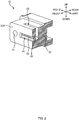
- FIG. 2 is a cut perspective view of the ferrule 12 according to a first embodiment.
- a direction of each fiber hole 22 is defined as a "front-rear direction", a side toward a ferrule 12 to be coupled is defined as “front”, and an opposite side is defined as “rear”.
- a direction in which two guide pin holes 21 of the ferrule 12 are aligned is defined as a "left-right direction", a right side when a front side is seen from a rear side is defined as “right”, and an opposite side is defined as "left”.
- a direction perpendicular to the front-rear direction and the left-right direction is defined as an "up-down direction”
- a side with an opening in an adhesive filling part 23 is defined as "up”
- an opposite side is defined as "down”.
- the ferrule 12 is a member that holds end portions of optical fibers for transmitting optical signals.
- a front endface (ferrule endface 12A) of the ferrule 12 serves as an endface to come into contact with an endface of the ferrule to be coupled (or an inner wall surface of the adapter 15).
- the ferrule 12 of the present embodiment is integrally molded by resin (e.g., transparent resin) that allows transmission of an optical signal. End portions of the plurality of optical fibers (not illustrated) are held inside this ferrule 12.
- the ferrule 12 includes the paired guide pin holes 21, a plurality of fiber holes 22, the adhesive filling part 23, a recess 24, a plurality of lens parts 25, and a light transmission part 26.
- the paired guide pin holes 21 are formed at an interval in the left-right direction. Since Fig. 2 is a cross-sectional view, only one of the guide pin holes 21 is illustrated in the drawing.
- the plurality of fiber holes 22 are arranged between the paired guide pin holes 21.
- the unillustrated optical fibers are inserted into the respective fiber holes 22 and are fixed to the ferrule 12 with an adhesive agent filled into the adhesive filling part 23 in a state where the endfaces of the optical fibers abut a wall surface facing opening surfaces of the fiber holes 22 (front wall surface of inner wall surfaces of the adhesive filling part 23) .
- the recess 24 is a part recessed from the ferrule endface 12A.
- the recess 24 is provided between the two guide pin holes 21 in the ferrule endface 12A.
- the recess 24 has a long narrow rectangular shape in the left-right direction so as to correspond to the plurality of optical fiber holes 22.
- the lens parts 25 are provided in a bottom surface of the recess 24. With the lens parts 25 being provided in the bottom surface of the recess 24, when the ferrules 12 come to abut each other (the ferrule endfaces 12A are brought into contact with each other), the lens parts 25 are prevented from coming into contact with each other (the lens parts 25 can be maintained in a non-contacting state) .
- the lens parts 25 are arranged so as to correspond to the plurality of respective optical fibers. An optical signal from each of the optical fibers is input and/or output through the corresponding lens part 25.
- a surface of each of the lens parts 25 (lens surface) serves as a region to and/or from which an optical signal inputs and/or outputs (optical signal region) .
- the surface of the lens part 25 (lens surface) serves as a region through which an optical signal passes.
- the lens part 25 is formed so as to function, for example, as a collimating lens.
- the light transmission part 26 is a part that allows optical signals to be transmitted between the endfaces of the optical fibers (not illustrated) and the lens parts 25. Hence, the light transmission part 26 is a part serving as optical paths of the optical signals. Note that, although the ferrule 12 is integrally molded by transparent resin in the present embodiment, components and materials forming the ferrule 12 are not limited to transparent resin as long as at least the lens parts 25 and the light transmission part 26 can transmit optical signals.
- FIG. 10A and Fig. 10B are explanatory diagrams illustrating the cleaning member 31 according to the comparative example.
- an adhesive body 35 having a flat surface is formed by applying an adhesive agent to a base 33.
- a surface of the adhesive body 35 is flat, this makes it difficult for the adhesive body 35 to be fully in contact with the lens parts 25 (specifically, the surfaces of the lens parts 25) each serving as a region where an optical signal enters and is emitted (optical signal region) .
- the lens parts 25 in a state where the recess 24 is formed in the ferrule endface 12A and the surfaces of the lens parts 25 (optical signal regions) are placed in the recess 24 as in the ferrule 12 of the present embodiment, it is difficult for the lens parts 25 to be fully in contact with the adhesive body 35 when the surface of the adhesive body 35 is flat as in the comparative example. Consequently, the contact between the lens parts 25 and the adhesive body 35 may be insufficient (the area of the contact may be insufficient, or force applied for the contact may be insufficient), which may result in insufficient removal of dust adhering to the lens parts 25.
- the cleaning member 31 needs to be pressed against the ferrule 12 with a high pressure. Additionally, such an increase in pressure to be applied to press the cleaning member 31 against the ferrule 12 causes damaging of the adhesive body 35 at the time of cleaning to progress, which reduces the number of times the cleaning member 31 can be used (number of times the cleaning member 31 can be repeatedly used).
- Fig. 3A and Fig. 3B are explanatory diagrams illustrating the cleaning member 31 according to the first embodiment.
- the cleaning member 31 includes the base 33 and the adhesive body 35.
- the base 33 is a member that holds the adhesive body 35.
- the base 33 with an adhesive agent enables the flexible adhesive body 35 to be pressed against the ferrule 12.
- An endface of the base 33 is formed to be larger than the regions where optical signals enter and are emitted (optical signal regions) .
- the endface of the base 33 is formed larger than a region in which the plurality of lens parts 25 are formed and is also formed larger than the recess 24 of the ferrule 12.
- the adhesive body 35 is a member for causing dust to adhere, and is an adhesive member.
- the adhesive body 35 is a member to be brought into contact with the regions where optical signals of the optical connector enter and are emitted (optical signal regions) .
- the adhesive body 35 can be used, not only for the cleaning tool 30 of the present embodiment, but also for another member to be used for causing dust to adhere.
- the adhesive body 35 has such a degree of adhesiveness that, when the adhesive body 35 is brought into contact with and then removed from the ferrule endface 12A, any part of the adhesive body 35 would not remain on the ferrule endface 12A.
- the adhesive agent to be used for the adhesive body 35 is desired to have removability, and not to be ruptured or the like even if the connector endface is uneven, and at the same time not to remain after being removed, not to come off or have any bubbles in a heat shock test or the like, and to have elastic deformability to be able to fit the uneven surface and restorability against stress.
- a constituent of an adhesive agent having such properties include acrylic resin, a rubber-based material represented by butyl rubber, isoprene rubber, styrene-butadiene rubber, and the like, polyvinyl ether resin, silicone resin, and urethane rubber, and any of the above can be selected for use. Acrylic adhesive is most preferable.
- the adhesive body according to the present embodiment at least has properties that are capable of compressive deformation, extension deformation, and shear deformation by elastic deformation.
- the adhesive body 35 preferably has a storage elastic modulus in the range from 1.0 ⁇ 10 4 Pa to 1.0 ⁇ 10 6 Pa. With the storage elastic modulus of the adhesive body 35 being within the above range, this exerts effects of making it easier for the abutting surface of the adhesive body 35 to be fully in contact with the portions where optical signals enter and are emitted, which enables suitable collection of dust.
- the storage elastic modulus (Pa) indicates a measurement result at 20°C when the measurement was performed under the following conditions.
- Measuring device MARS I (manufactured by Haaketechnik), probe diameter: 8 mm ⁇ , sample thickness: 4 mm, load: 5 N, frequency: 1 Hz, rate of temperature increase: 10°C/min
- the adhesive body 35 according to the present embodiment preferably has peeling force of 0.1 to 10 N / 20 mm.
- the peeling force being within the above range, restorability against stress can be applied and suitable degrees of adhesive strength and peeling force can be maintained, when the adhesive body 35 of the cleaning tool 30 of the present embodiment is pressed against the portions where optical signals enter and are emitted to be elastically deformed.
- the adhesive body 35 according to the present embodiment it is possible to have a high performance of dust removal, to have little adhesive remained, and to perform sufficient cleaning.
- the peeling force is lower than 0.1 N / 20 mm, it may be more likely to have a reduction in performance of dust removal, for the adhesive body to rupture, and for adhesive to remain.
- the peeling force exceeds 10 N / 20 mm, it may be more likely for adhesive to remain.
- peeling force refers to a value obtained by measuring, using a method conforming to JIS Z 2037: 2009, a sample of an adhesive body having a size of 20 mm ⁇ 90 mm and a thickness of 4 mm and stacked with a PET film.
- the adhesive body 35 of the present embodiment includes a protrusion 35A protruding in a region coming into contact with each of the lens parts 25.
- the protrusion 35A is easier to come into contact with the corresponding lens part 25, and consequently the adhesive body 35 having adhesiveness can be fully in contact with the lens part 25.
- a sufficient contact area can be secured, and the adhesive body 35 can be in contact with the lens parts 25 (optical signal regions) with sufficient force.
- the lens parts 25 and the adhesive body 35 can be fully in contact with each other, which consequently makes it easier to remove dust adhering to the lens parts 25.
- the adhesive body 35 can be in contact with the lens parts 25 (optical signal regions) with sufficient force at the protrusion 35A, which facilitates cleaning operation. Additionally, since the pressure to be applied to press the cleaning member 31 against the ferrule 12 may be low, damage to the adhesive body 35 at the time of cleaning can be reduced, which can increase the number of times the cleaning member 31 can be used (number of times the cleaning member 31 can be repeatedly used).
- the adhesive body 35 desirably includes a plurality of protrusions 35A so that the protrusions 35A correspond to the respective lens parts 25.
- the adhesive body 35 preferably includes the plurality of protrusions 35A arranged to align in the left-right direction. With this, each of the protrusions 35A comes into contact with a corresponding one of the lens parts 25, which makes easier for the protrusions 35A to be in contact with the lens parts 25.
- a single protrusion 35A may be formed as a ridge (streak) to be in contact with the plurality of lens parts 25 (optical signal regions) .
- the adhesive body 35 may include the protrusion 35A (ridge) linearly protruding in the left-right direction.
- the protrusion 35A can also be in contact with each of all the lens parts 25 in this configuration. Forming the protrusion as a ridge can simplify the shape of the protrusion.
- the protrusion(s) 35A of the adhesive body 35 of the present embodiment protrudes in a region to be in contact with the lens parts 25, the lens parts 25 can be fully in contact with the adhesive body 35 even in a state where the lens parts 25 (optical signal regions) are arranged in the recess 24.
- the cleaning tool 30 including the adhesive body 35 with the protrusion(s) 35A is particularly effective when the recess 24 is formed in the endface of the optical connector 11 (note that, however, the optical connector 11 to be a cleaning target is not limited to an optical connector including the recess 24 in the endface, as will be described later).
- the protruding amount B is desirably greater than A (B > A). This makes it easier for the protrusion 35A to come into contact with the lens part 25, which consequently makes it easier for the adhesive body 35 to be fully in contact with the lens parts 25.
- the protrusion 35A can be in contact with the lens part 25 with the base part 35B being deformed at the time of cleaning even if the protruding amount B from the base part 35B is smaller than A.
- the thickness of the base part 35B is C
- the thickness B + C of the adhesive body 35 including the base part 35B at the protrusion 35A is desirably greater than A (B + C > A).
- the protrusion 35A of the adhesive body 35 has bendability (preferable elastic deformation properties), and hence, even when the optical signal region (region where an optical signal enters and is emitted) has a curved surface as a lens surface of the lens part 25, the protrusion 35A can have an intimate contact with the curved surface.
- the cleaning tool 30 includes the connector part 321 for aligning the cleaning member 31 with the optical connector 11.
- the cleaning tool 30 including the connector part 321 enables alignment of the lens parts 25 (optical signal regions) of the optical connector 11 with the protrusion(s) 35A, which makes it possible for the protrusion (s) 35A to be surely in contact with the lens parts 25 (optical signal regions).
- the connector part 321 corresponds to an alignment part for aligning the position (s) of the protrusion (s) 35A with the optical signal regions of the optical connector 11.
- the alignment part for aligning the position(s) of the protrusion(s) 35A with the optical signal regions of the optical connector 11 is not limited to the connector part 321.
- the alignment part of the cleaning tool 30 may be formed to directly align the optical connector 11 and the cleaning member 31 (or the protrusion(s) 35A) without using the adapter 15.
- the cleaning tool 30 may include alignment pins (alignment part) .
- the alignment pins may be fitted to the guide pin holes 21 of the ferrule 12 to directly align the optical connector 11 and the cleaning member 31 (or the protrusion(s) 35A).
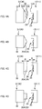
- Fig. 4A is an explanatory diagram of an adhesive body 35 according to a first modified example.
- a ferrule 12 of the first modified example to be a cleaning target includes two lens parts 25 arranged side by side in an up-down direction.
- the adhesive body 35 may include a plurality of protrusions 35A aligned in the up-down direction so that the protrusions 35A correspond to the respective lens parts 25.
- Each of the protrusions 35A in Fig. 4A may be a protrusion 35A (ridge) protruding linearly in the left-right direction (direction perpendicular to the sheet in Fig. 4A ).
- the adhesive body 35 since the adhesive body 35 includes the protrusions 35A each protruding in a region to be in contact with the corresponding lens part 25, this makes easier for the protrusion 35A to come into contact with the lens part 25, and consequently the adhesive body 35 having adhesiveness can be fully in contact with the lens parts 25.
- Fig. 4B is an explanatory diagram of an adhesive body 35 according to a second modified example.
- the adhesive body 35 does not include any base part 35B or has no boundary between a base part 35B and a protrusion 35A.
- the adhesive body 35 since the adhesive body 35 includes the protrusion 35A protruding in a region to be in contact with the lens part 25, this makes it easier for the protrusion 35A to come into contact with the lens part 25, and consequently the adhesive body 35 having adhesiveness can be fully in contact with the lens parts 25.
- Fig. 4C is an explanatory diagram illustrating an adhesive body 35 according to a third modified example.
- the adhesive body 35 does not include any base part 35B.
- an endface of a protrusion 35A is formed to be flat instead of being convex.
- the adhesive body 35 since the adhesive body 35 includes the protrusion 35A protruding in a region to be in contact with lens parts 25, this makes it easier for the protrusion 35A to come into contact with the lens parts 25, and consequently the adhesive body 35 having adhesiveness can be fully in contact with the lens parts 25.
- the protruding amount B is desirably greater than A (B > A).
- Fig. 4D is an explanatory diagram illustrating an adhesive body 35 according to a fourth modified example.
- the fourth modified example compared with the third modified example, recesses (recessed portions) along curved surfaces of lens parts 25 are formed in an endface of a protrusion 35A.
- the adhesive body 35 since the adhesive body 35 includes the protrusion 35A protruding in a region to be in contact with the lens parts 25, this makes it easier for the protrusion 35A to come into contact with the lens parts 25, and consequently the adhesive body 35 having adhesiveness can be fully in contact with the lens parts 25.
- Fig. 5 is a flowchart of a method for manufacturing the cleaning member 31.
- an adhesive agent is filled into a mold (S001) and is cured (S002), to mold the adhesive body 35. Thereafter, the adhesive body 35 is taken out from the mold (S003) and is then fixed to the base 33 (S004).
- the adhesive body 35 is adhesion-fixed to the base 33 with the adhesive agent.
- the method of fixing the adhesive body 35 to the base 33 is not limited to adhesion fixing.
- Fig. 6 is a flowchart of another method for manufacturing the cleaning member 31.
- an adhesive agent is applied to the base 33 to form the base part 35B of the adhesive body 35 (S101) .
- an adhesive agent is further applied onto the base part 35B formed on the base 33, to form the protrusion (s) 35A (S102) .
- the base part 35B and the protrusion (s) 35A may be cured separately by performing a step of curing the adhesive agent after each of steps S101 and S102, or the base part 35B and the protrusion (s) 35A may be cured together after step S102.
- a 3D printer may be used, but another application method may be employed.
- Fig. 7A and Fig. 7B are explanatory diagrams illustrating a cleaning target according to a second embodiment.
- Fig. 7A is an explanatory diagram illustrating a vicinity of an optical signal region according to the second embodiment.
- Fig. 7B is a perspective view of a ferrule 12 according to the second embodiment.
- the lensed fiber 1 is an optical fiber formed by fusion-splicing a GRIN lens 5 to a tip of a single-mode optical fiber 3.
- a flat plate 41 capable of transmitting an optical signal is provided to an endface of the ferrule 12. This allows the flat plate 41 to be arranged ahead of the lensed fibers 1 inserted into the respective fiber holes 22 of the ferrule 12.
- the flat plate 41 is provided perpendicularly to an optical axis of the lensed fiber 1. Note that a refractive index matching material 7 is filled (into a space) between the flat plate 41 and an endface of the lensed fiber 1.
- a matching material filling part 28 for filling the refractive index matching material 7 is provided in the ferrule 12.
- each region through which parallel light passes in the outer surface of the flat plate 41 serves as an optical signal region where an optical signal enters and is emitted.
- Fig. 8A and Fig. 8B are explanatory diagrams illustrating the ferrule 12 of the second embodiment at the time of cleaning.
- the cleaning member 31 includes a base 33 and an adhesive body 35 as in the first embodiment.
- the adhesive body 35 includes a protrusion 35A protruding in a region to be in contact with the optical signal region as in the first embodiment.
- a sufficient contact area can be secured, and the adhesive body 35 can be in contact with the optical signal region with sufficient force.
- the optical signal region and the adhesive body 35 can be fully in contact with each other, which consequently makes it easier to remove dust adhering to the optical signal region.
- the adhesive body 35 can be in contact with the optical signal region with sufficient force at the protrusion 35A, which facilitates cleaning operation.
- the pressure to be applied to press the cleaning member 31 against the ferrule 12 may be low, damage to the adhesive body 35 at the time of cleaning can be reduced, which can increase the number of times the cleaning member 31 can be used (number of times the cleaning member 31 can be repeatedly used).
- each of the lens parts 25 serves as an optical signal region (region where an optical signal enters and is emitted or a region to be in contact with the protrusion 35A of the adhesive body 35) .
- the optical signal region may be a flat surface as the outer surface of the flat plate 41 instead of a curved surface as the surface of the lens part 25.
- the cleaning tool 30 includes the connector part 321 and the operation part 322 as illustrated in Fig. 1A and Fig. 1B .
- the cleaning tool 30 is inserted into one of the connector insertion openings of the adapter 15 to thereby clean the connection surface of the ferrule 12 of the optical connector 11.
- the cleaning tool 30 is not limited to such a shape and usage.
- Fig. 9A and Fig. 9B are explanatory diagrams illustrating a cleaning tool 30 according to a third embodiment.
- the cleaning tool 30 according to the third embodiment is formed as a cap that protects the connection surface of the ferrule 12 of the optical connector 11.
- the cleaning tool 30 of the third embodiment includes a cleaning member 31 and a cap part 323.
- the cleaning member 31 is formed similarly to that of the above-described embodiments.
- the cleaning member 31 includes the above-described adhesive body 35 (not illustrated in Fig. 9A and Fig. 9B ), and the adhesive body 35 includes a protrusion 35A (not illustrated in Fig. 9A and Fig. 9B ) protruding in a region to be in contact with an optical signal region.
- the cap part 323 is a part that protects the connection surface of the ferrule 12 of the optical connector 11 and is formed to be detachable from the optical connector 11.
- the connection surface of the ferrule 12 of the optical connector 11 can be protected by the cap part 323.
- the adhesive body 35 coming into contact with the connection surface of the ferrule 12 dust on the connection surface of the ferrule 12 is caused to adhere to the adhesive body 35 to thereby be able to remove the dust.
- the cleaning tool 30 may be formed as a cap and may be formed as another member.
- the adhesive body 35 may be used for other kinds of cleaning tool instead of being used only for the above-described cleaning tool 30.
- the adhesive body 35 may further be used, without being limited to a cleaning tool, for various purposes as long as the purposes are to be in contact with an optical connector.
Landscapes
- Physics & Mathematics (AREA)
- General Physics & Mathematics (AREA)
- Optics & Photonics (AREA)
- Optical Couplings Of Light Guides (AREA)
- Mechanical Coupling Of Light Guides (AREA)
- Cleaning In General (AREA)
Abstract

Description
- The present invention relates to a cleaning tool and an adhesive body.
- Dust or the like adhering to an endface of an optical connector causes an increase in loss of optical signals and the like. To avoid this, cleaning of the endface of the optical connector is needed.
Patent Literature 1 describes a cleaning tool that includes a pad-shaped cleaning member having an abutting surface to abut on a joint endface of an optical connector and that is self-adhesive at the abutting surface.Patent Literature 2 describes an adhesive agent to be used for an optical connector cleaner for cleaning a connecting endface of an optical connector. -
- Patent Literature 1:
JP 2002-219421A - Patent Literature 2:
JP 2008-180799A - In a case of cleaning an endface of an optical connector, it is important to remove dust adhering to a portion where an optical signal enters and is emitted in the endface of the optical connector. Hence, when a pad-shaped adhesive cleaning member is to abut on the endface of the optical connector, the cleaning member needs to fully abut on the portion where an optical signal enters and is emitted in the endface of the optical connector. However, in the case of the cleaning tool described in
Patent Literature 1, an abutting surface of the cleaning member is flat in shape, and therefore it is difficult to cause the cleaning member to fully abut on the portion where an optical signal enters and is emitted, in the endface of the optical connector. This consequently causes problems that the contact between the optical connector and the cleaning member is insufficient, that the cleaning member needs to be pressed against the optical connector with high pressure, and the like. - An objective of some embodiments of the present invention is to allow a cleaning member to be fully in contact with a portion where an optical signal enters and is emitted.
- Some embodiments of the present invention are a cleaning tool for cleaning an optical connector, the cleaning tool comprising an adhesive part to be in contact with an optical signal region where an optical signal enters and is emitted in the optical connector, wherein the adhesive body includes a protrusion protruding in a region to be in contact with the optical signal region.
- Other features of the present invention are made clear by the following description and the drawings.
- According to some embodiments of the present invention, it is possible to cause a cleaning member to be fully in contact with a portion where an optical signal enters and is emitted.
-
- [
Fig. 1] Fig. 1A and Fig. 1B are explanatory diagrams illustrating acleaning tool 30 according to the present embodiment. - [
Fig. 2] Fig. 2 is a cut perspective view of aferrule 12 according to a first embodiment. - [
Fig. 3] Fig. 3A and Fig. 3B are explanatory diagrams illustrating acleaning member 31 according to the first embodiment. - [
Fig. 4] Fig. 4A is an explanatory diagram illustrating anadhesive body 35 according to a first modified example.Fig. 4B is an explanatory diagram illustrating anadhesive body 35 according to a second modified example.Fig. 4C is an explanatory diagram illustrating anadhesive body 35 according to a third modified example.Fig. 4D is an explanatory diagram illustrating anadhesive body 35 according to a fourth modified example. - [
Fig. 5] Fig. 5 is a flowchart of a method for manufacturing thecleaning member 31. - [
Fig. 6] Fig. 6 is a flowchart of another method for manufacturing thecleaning member 31. - [
Fig. 7] Fig. 7A and Fig. 7B are explanatory diagrams illustrating a cleaning target according to a second embodiment.Fig. 7A is an explanatory diagram illustrating a vicinity of an optical signal region according to the second embodiment.Fig. 7B is a perspective view of aferrule 12 according to the second embodiment. - [
Fig. 8] Fig. 8A and Fig. 8B are explanatory diagrams illustrating theferrule 12 according to the second embodiment at the time of cleaning. - [
Fig. 9] Fig. 9A and Fig. 9B are explanatory diagrams illustrating acleaning tool 30 according to a third embodiment. - [
Fig. 10] Fig. 10A and Fig. 10B are explanatory diagrams illustrating acleaning member 31 according to a comparative example. - At least the following matters are made clear from the following description and the drawings.
- A cleaning tool for cleaning an optical connector, the cleaning tool comprising an adhesive part to be in contact with an optical signal region where an optical signal enters and is emitted in the optical connector, wherein the adhesive body includes a protrusion protruding in a region to be in contact with the optical signal region. According to such a cleaning tool, it is possible to allow the cleaning member to be fully in contact with the portion where an optical signal enters and is emitted.
- The adhesive body preferably includes a plurality of the protrusions to be in contact with a plurality of the optical signal regions. With this, each protrusion comes into contact with a corresponding optical signal region, which makes it easier for the protrusion to be in contact with the optical signal region.
- The protrusion is preferably formed linearly, and the protrusion is preferably formed to be in contact with a plurality of the optical signal regions. With this, it is possible to simplify the shape of the protrusion.
- A recess is preferably formed in an endface of the optical connector. Including the protrusion is particularly effective in such a case.
- Preferably B > A where A is a length between the endface and the optical signal region, and B is a protruding amount of the protrusion. This makes it easier for the protrusion to be in contact with the optical signal region, and consequently makes it easier for the adhesive body and the optical signal region to be fully in contact with each other.
- A lens part serving as the optical signal region is preferably formed in a bottom portion of the recess. Including the protrusion is particularly effective in such a case.
- The adhesive body preferably includes a base part, and the protrusion is preferably formed to protrude from the base part. With this, it is possible to allow the cleaning member to be fully in contact with the portion where an optical signal enters and is emitted.
- Preferably B + C > A where A is a length between an endface of the optical connector and the optical signal region, B is a protruding amount of the protrusion, and C is a thickness of the base part. This makes it easier for the protrusion to be in contact with the optical signal region, and consequently makes it easier for the adhesive body and the optical signal region to be fully in contact with each other.
- The cleaning tool preferably comprising an alignment part for aligning a position of the protrusion with the optical signal region of the optical connector. With this, it is possible to allow the protrusion to be surely in contact with the optical region.
- An adhesive body to be in contact with an optical signal region where an optical signal enters and is emitted in an optical connector will become clear, the adhesive body comprising a protrusion protruding in a region to be in contact with the optical signal region of the optical connector. With such an adhesive body, it is possible to be fully in contact with the portion where an optical signal enters and is emitted.
- The adhesive body preferably comprising a plurality of the protrusions to be in contact with a plurality of the optical signal regions. With this, each protrusion comes into contact with a corresponding optical signal region, which makes it easier for the protrusion to be in contact with the optical signal region.
- The protrusion is preferably formed linearly, and the protrusion is preferably formed to be in contact with a plurality of the optical signal regions. With this, it is possible to simplify the shape of the protrusion.
- The adhesive body preferably includes a base part, and the protrusion is preferably formed to protrude from the base part. With this, it is possible to be fully in contact with the portion where an optical signal enters and is emitted.
-
Fig. 1A and Fig. 1B are explanatory diagrams illustrating acleaning tool 30 according to the present embodiment. Anoptical connector 11, anadapter 15, and acleaning tool 30 are included in the drawings. - The
optical connector 11 is provided to an end portion of each optical fiber and is a connecting component for optically connecting optical fibers to each other. Theoptical connector 11 is, for example, an MPO optical connector (F13 type multicore optical fiber connector according to JIS C 5982). Theoptical connector 11 includes aferrule 12 and ahousing 13. Theferrule 12 is a member that holds end portions of the optical fibers. A structure of theferrule 12 of the present embodiment is to be described later. Thehousing 13 is a member that holds theferrule 12. Thehousing 13 is formed to be able to be coupled with theadapter 15. - The
adapter 15 is a component for connectingoptical connectors 11 to each other. A connector insertion opening (not illustrated) is formed at each of both ends of theadapter 15. When theoptical connectors 11 are inserted into the respective connector insertion openings, theferrules 12 of theoptical connectors 11 abut on each other to optically connect theoptical connectors 11 to each other (to optically connect the optical fibers of theoptical connectors 11 to each other) . In the present embodiment, thecleaning tool 30 is inserted into one of the connector insertion openings of the adapter 15 (refer toFig. 1A and Fig. 1B ), to clean a connection surface of theferrule 12 of theoptical connector 11 inserted into the other connector insertion opening. - The
cleaning tool 30 is a tool for cleaning the connection surface (optical signal surface) of theferrule 12. Thecleaning tool 30 includes a cleaningmember 31, aconnector part 321, and anoperation part 322. - The cleaning
member 31 is a member for cleaning the connection surface (optical signal surface) of theferrule 12. In the present embodiment, an adhesive body 35 (to be described later) is provided to an endface of the cleaningmember 31. Theadhesive body 35 is brought into contact with the connection surface of theferrule 12 to cause dust on the connection surface of theferrule 12 to adhere to theadhesive body 35. In this way, the dust is removed. - The
connector part 321 is a part to couple thecleaning tool 30 with theadapter 15. When thecleaning tool 30 is inserted into theadapter 15, theconnector part 321 engages with theadapter 15 to thereby couple thecleaning tool 30 with theadapter 15. To enable this, theconnector part 321 has substantially the same shape as that of thehousing 13 of theoptical connector 11. With thecleaning tool 30 including theconnector part 321, it makes it easy to align the cleaningmember 31 with theoptical connector 11. Note that, however, thecleaning tool 30 may not necessarily include theconnector part 321. - The
operation part 322 is a part for an operator to operate (hold) thecleaning tool 30. Note that, however, thecleaning tool 30 may not necessarily include theoperation part 322. - Before a detailed description of the cleaning
member 31 of thecleaning tool 30, a structure of theferrule 12 of theoptical connector 11 to be a cleaning target will be described first.Fig. 2 is a cut perspective view of theferrule 12 according to a first embodiment. - In the following description about the
ferrule 12, directions will be defined as illustrated in the drawings. Specifically, a direction of eachfiber hole 22 is defined as a "front-rear direction", a side toward aferrule 12 to be coupled is defined as "front", and an opposite side is defined as "rear". Further, a direction in which two guide pin holes 21 of theferrule 12 are aligned is defined as a "left-right direction", a right side when a front side is seen from a rear side is defined as "right", and an opposite side is defined as "left". Further, a direction perpendicular to the front-rear direction and the left-right direction is defined as an "up-down direction", a side with an opening in an adhesive fillingpart 23 is defined as "up", and an opposite side is defined as "down". - The
ferrule 12 is a member that holds end portions of optical fibers for transmitting optical signals. A front endface (ferrule endface 12A) of theferrule 12 serves as an endface to come into contact with an endface of the ferrule to be coupled (or an inner wall surface of the adapter 15). Theferrule 12 of the present embodiment is integrally molded by resin (e.g., transparent resin) that allows transmission of an optical signal. End portions of the plurality of optical fibers (not illustrated) are held inside thisferrule 12. - The
ferrule 12 includes the paired guide pin holes 21, a plurality of fiber holes 22, the adhesive fillingpart 23, arecess 24, a plurality oflens parts 25, and alight transmission part 26. The paired guide pin holes 21 are formed at an interval in the left-right direction. SinceFig. 2 is a cross-sectional view, only one of the guide pin holes 21 is illustrated in the drawing. The plurality of fiber holes 22 are arranged between the paired guide pin holes 21. The unillustrated optical fibers are inserted into the respective fiber holes 22 and are fixed to theferrule 12 with an adhesive agent filled into the adhesive fillingpart 23 in a state where the endfaces of the optical fibers abut a wall surface facing opening surfaces of the fiber holes 22 (front wall surface of inner wall surfaces of the adhesive filling part 23) . - The
recess 24 is a part recessed from theferrule endface 12A. Therecess 24 is provided between the two guide pin holes 21 in theferrule endface 12A. Therecess 24 has a long narrow rectangular shape in the left-right direction so as to correspond to the plurality of optical fiber holes 22. - The
lens parts 25 are provided in a bottom surface of therecess 24. With thelens parts 25 being provided in the bottom surface of therecess 24, when theferrules 12 come to abut each other (the ferrule endfaces 12A are brought into contact with each other), thelens parts 25 are prevented from coming into contact with each other (thelens parts 25 can be maintained in a non-contacting state) . Thelens parts 25 are arranged so as to correspond to the plurality of respective optical fibers. An optical signal from each of the optical fibers is input and/or output through the correspondinglens part 25. Hence, a surface of each of the lens parts 25 (lens surface) serves as a region to and/or from which an optical signal inputs and/or outputs (optical signal region) . In other words, the surface of the lens part 25 (lens surface) serves as a region through which an optical signal passes. Thelens part 25 is formed so as to function, for example, as a collimating lens. By inputting and/or outputting an optical signal having a diameter magnified by thelens part 25, influence of misalignment of an optical path and the like can be reduced, and consequently a transmission loss of an optical signal can be suppressed. - The
light transmission part 26 is a part that allows optical signals to be transmitted between the endfaces of the optical fibers (not illustrated) and thelens parts 25. Hence, thelight transmission part 26 is a part serving as optical paths of the optical signals. Note that, although theferrule 12 is integrally molded by transparent resin in the present embodiment, components and materials forming theferrule 12 are not limited to transparent resin as long as at least thelens parts 25 and thelight transmission part 26 can transmit optical signals. - Before a description of the
cleaning tool 31 according to the present embodiment, a cleaningmember 31 according to a comparative example will be described first.Fig. 10A and Fig. 10B are explanatory diagrams illustrating the cleaningmember 31 according to the comparative example. - In the cleaning
member 31 of the comparative example, anadhesive body 35 having a flat surface is formed by applying an adhesive agent to abase 33. In the comparative example, since a surface of theadhesive body 35 is flat, this makes it difficult for theadhesive body 35 to be fully in contact with the lens parts 25 (specifically, the surfaces of the lens parts 25) each serving as a region where an optical signal enters and is emitted (optical signal region) . In particular, in a state where therecess 24 is formed in theferrule endface 12A and the surfaces of the lens parts 25 (optical signal regions) are placed in therecess 24 as in theferrule 12 of the present embodiment, it is difficult for thelens parts 25 to be fully in contact with theadhesive body 35 when the surface of theadhesive body 35 is flat as in the comparative example. Consequently, the contact between thelens parts 25 and theadhesive body 35 may be insufficient (the area of the contact may be insufficient, or force applied for the contact may be insufficient), which may result in insufficient removal of dust adhering to thelens parts 25. Moreover, for thelens parts 25 and theadhesive body 35 to be fully in contact with each other, the cleaningmember 31 needs to be pressed against theferrule 12 with a high pressure. Additionally, such an increase in pressure to be applied to press the cleaningmember 31 against theferrule 12 causes damaging of theadhesive body 35 at the time of cleaning to progress, which reduces the number of times the cleaningmember 31 can be used (number of times the cleaningmember 31 can be repeatedly used). -
Fig. 3A and Fig. 3B are explanatory diagrams illustrating the cleaningmember 31 according to the first embodiment. - The cleaning
member 31 includes thebase 33 and theadhesive body 35. Thebase 33 is a member that holds theadhesive body 35. - The base 33 with an adhesive agent enables the flexible
adhesive body 35 to be pressed against theferrule 12. An endface of thebase 33 is formed to be larger than the regions where optical signals enter and are emitted (optical signal regions) . Here, the endface of thebase 33 is formed larger than a region in which the plurality oflens parts 25 are formed and is also formed larger than therecess 24 of theferrule 12. - The
adhesive body 35 is a member for causing dust to adhere, and is an adhesive member. Theadhesive body 35 is a member to be brought into contact with the regions where optical signals of the optical connector enter and are emitted (optical signal regions) . Theadhesive body 35 can be used, not only for thecleaning tool 30 of the present embodiment, but also for another member to be used for causing dust to adhere. Theadhesive body 35 has such a degree of adhesiveness that, when theadhesive body 35 is brought into contact with and then removed from theferrule endface 12A, any part of theadhesive body 35 would not remain on theferrule endface 12A. The adhesive agent to be used for theadhesive body 35 is desired to have removability, and not to be ruptured or the like even if the connector endface is uneven, and at the same time not to remain after being removed, not to come off or have any bubbles in a heat shock test or the like, and to have elastic deformability to be able to fit the uneven surface and restorability against stress. Examples of a constituent of an adhesive agent having such properties include acrylic resin, a rubber-based material represented by butyl rubber, isoprene rubber, styrene-butadiene rubber, and the like, polyvinyl ether resin, silicone resin, and urethane rubber, and any of the above can be selected for use. Acrylic adhesive is most preferable. - The adhesive body according to the present embodiment at least has properties that are capable of compressive deformation, extension deformation, and shear deformation by elastic deformation.
- The
adhesive body 35 according to the present embodiment preferably has a storage elastic modulus in the range from 1.0 ∗ 104 Pa to 1.0 ∗ 106 Pa. With the storage elastic modulus of theadhesive body 35 being within the above range, this exerts effects of making it easier for the abutting surface of theadhesive body 35 to be fully in contact with the portions where optical signals enter and are emitted, which enables suitable collection of dust. The storage elastic modulus (Pa) indicates a measurement result at 20°C when the measurement was performed under the following conditions. - Measuring device: MARS I (manufactured by Haake Technik), probe diameter: 8 mmϕ, sample thickness: 4 mm, load: 5 N, frequency: 1 Hz, rate of temperature increase: 10°C/min
- The
adhesive body 35 according to the present embodiment preferably has peeling force of 0.1 to 10 N / 20 mm. With the peeling force being within the above range, restorability against stress can be applied and suitable degrees of adhesive strength and peeling force can be maintained, when theadhesive body 35 of thecleaning tool 30 of the present embodiment is pressed against the portions where optical signals enter and are emitted to be elastically deformed. Hence, with theadhesive body 35 according to the present embodiment, it is possible to have a high performance of dust removal, to have little adhesive remained, and to perform sufficient cleaning. When the peeling force is lower than 0.1 N / 20 mm, it may be more likely to have a reduction in performance of dust removal, for the adhesive body to rupture, and for adhesive to remain. When the peeling force exceeds 10 N / 20 mm, it may be more likely for adhesive to remain. - Note that in the present description, peeling force refers to a value obtained by measuring, using a method conforming to JIS Z 2037: 2009, a sample of an adhesive body having a size of 20 mm ∗ 90 mm and a thickness of 4 mm and stacked with a PET film.
- As illustrated in
Fig. 3A , theadhesive body 35 of the present embodiment includes aprotrusion 35A protruding in a region coming into contact with each of thelens parts 25. With this, as illustrated inFig. 3B , theprotrusion 35A is easier to come into contact with the correspondinglens part 25, and consequently theadhesive body 35 having adhesiveness can be fully in contact with thelens part 25. In other words, according to the present embodiment, a sufficient contact area can be secured, and theadhesive body 35 can be in contact with the lens parts 25 (optical signal regions) with sufficient force. Hence, according to the present embodiment, thelens parts 25 and theadhesive body 35 can be fully in contact with each other, which consequently makes it easier to remove dust adhering to thelens parts 25. Moreover, according to the present embodiment, even when the pressure to be applied to press the cleaningmember 31 against theferrule 12 is reduced, theadhesive body 35 can be in contact with the lens parts 25 (optical signal regions) with sufficient force at theprotrusion 35A, which facilitates cleaning operation. Additionally, since the pressure to be applied to press the cleaningmember 31 against theferrule 12 may be low, damage to theadhesive body 35 at the time of cleaning can be reduced, which can increase the number of times the cleaningmember 31 can be used (number of times the cleaningmember 31 can be repeatedly used). - In a case of including the plurality of lens parts 25 (optical signal regions), the
adhesive body 35 desirably includes a plurality ofprotrusions 35A so that theprotrusions 35A correspond to therespective lens parts 25. For example, in a case that the plurality oflens parts 25 are included as illustrated inFig. 2 , theadhesive body 35 preferably includes the plurality ofprotrusions 35A arranged to align in the left-right direction. With this, each of theprotrusions 35A comes into contact with a corresponding one of thelens parts 25, which makes easier for theprotrusions 35A to be in contact with thelens parts 25. - Alternatively, a
single protrusion 35A may be formed as a ridge (streak) to be in contact with the plurality of lens parts 25 (optical signal regions) . For example, in a case that the plurality oflens parts 25 are formed in a row in the left-right direction as illustrated inFig. 2 , theadhesive body 35 may include theprotrusion 35A (ridge) linearly protruding in the left-right direction. Theprotrusion 35A can also be in contact with each of all thelens parts 25 in this configuration. Forming the protrusion as a ridge can simplify the shape of the protrusion. - Since the protrusion(s) 35A of the
adhesive body 35 of the present embodiment protrudes in a region to be in contact with thelens parts 25, thelens parts 25 can be fully in contact with theadhesive body 35 even in a state where the lens parts 25 (optical signal regions) are arranged in therecess 24. As described above, thecleaning tool 30 including theadhesive body 35 with the protrusion(s) 35A is particularly effective when therecess 24 is formed in the endface of the optical connector 11 (note that, however, theoptical connector 11 to be a cleaning target is not limited to an optical connector including therecess 24 in the endface, as will be described later). - Assume, as illustrated in
Fig. 3A , that the front-rear direction length between theferrule endface 12A and the lens part 25 (optical signal region) is A and the protruding amount of theprotrusion 35A is B, the protruding amount B is desirably greater than A (B > A). This makes it easier for theprotrusion 35A to come into contact with thelens part 25, which consequently makes it easier for theadhesive body 35 to be fully in contact with thelens parts 25. - In a case, as illustrated in
Fig. 3A , that theadhesive body 35 includes abase part 35B and theprotrusion 35A are formed to protrude from thebase part 35B, theprotrusion 35A can be in contact with thelens part 25 with thebase part 35B being deformed at the time of cleaning even if the protruding amount B from thebase part 35B is smaller than A. In this case, assuming that the thickness of thebase part 35B is C, the thickness B + C of theadhesive body 35 including thebase part 35B at theprotrusion 35A is desirably greater than A (B + C > A). With this, thebase part 35B is deformed at the time of cleaning to thereby allow theprotrusion 35A to come into contact with thelens part 25, which consequently allows theadhesive body 35 to be fully in contact with thelens part 25. - As illustrated in
Fig. 3B , theprotrusion 35A of theadhesive body 35 has bendability (preferable elastic deformation properties), and hence, even when the optical signal region (region where an optical signal enters and is emitted) has a curved surface as a lens surface of thelens part 25, theprotrusion 35A can have an intimate contact with the curved surface. Hence, according to the present embodiment, it is possible to remove dust adhering to a curved surface as the lens surface of thelens part 25. - Moreover, as illustrated in
Fig. 1A , thecleaning tool 30 according to the present embodiment includes theconnector part 321 for aligning the cleaningmember 31 with theoptical connector 11. Thecleaning tool 30 including theconnector part 321 enables alignment of the lens parts 25 (optical signal regions) of theoptical connector 11 with the protrusion(s) 35A, which makes it possible for the protrusion (s) 35A to be surely in contact with the lens parts 25 (optical signal regions). Accordingly, theconnector part 321 corresponds to an alignment part for aligning the position (s) of the protrusion (s) 35A with the optical signal regions of theoptical connector 11. Note that the alignment part for aligning the position(s) of the protrusion(s) 35A with the optical signal regions of theoptical connector 11 is not limited to theconnector part 321. The alignment part of thecleaning tool 30 may be formed to directly align theoptical connector 11 and the cleaning member 31 (or the protrusion(s) 35A) without using theadapter 15. For example, thecleaning tool 30 may include alignment pins (alignment part) . The alignment pins may be fitted to the guide pin holes 21 of theferrule 12 to directly align theoptical connector 11 and the cleaning member 31 (or the protrusion(s) 35A). -
Fig. 4A is an explanatory diagram of anadhesive body 35 according to a first modified example. Aferrule 12 of the first modified example to be a cleaning target includes twolens parts 25 arranged side by side in an up-down direction. In such a case of including the plurality of lens parts 25 (optical signal regions) in the up-down direction, theadhesive body 35 may include a plurality ofprotrusions 35A aligned in the up-down direction so that theprotrusions 35A correspond to therespective lens parts 25. Each of theprotrusions 35A inFig. 4A may be aprotrusion 35A (ridge) protruding linearly in the left-right direction (direction perpendicular to the sheet inFig. 4A ). Also in the first modified example, since theadhesive body 35 includes theprotrusions 35A each protruding in a region to be in contact with the correspondinglens part 25, this makes easier for theprotrusion 35A to come into contact with thelens part 25, and consequently theadhesive body 35 having adhesiveness can be fully in contact with thelens parts 25. -
Fig. 4B is an explanatory diagram of anadhesive body 35 according to a second modified example. In the second modified example, theadhesive body 35 does not include anybase part 35B or has no boundary between abase part 35B and aprotrusion 35A. However, also in the second modified example, since theadhesive body 35 includes theprotrusion 35A protruding in a region to be in contact with thelens part 25, this makes it easier for theprotrusion 35A to come into contact with thelens part 25, and consequently theadhesive body 35 having adhesiveness can be fully in contact with thelens parts 25. -
Fig. 4C is an explanatory diagram illustrating anadhesive body 35 according to a third modified example. In the third modified example, theadhesive body 35 does not include anybase part 35B. Moreover, in the third modified example, an endface of aprotrusion 35A is formed to be flat instead of being convex. Also in the third modified example, since theadhesive body 35 includes theprotrusion 35A protruding in a region to be in contact withlens parts 25, this makes it easier for theprotrusion 35A to come into contact with thelens parts 25, and consequently theadhesive body 35 having adhesiveness can be fully in contact with thelens parts 25. Note that, also in the third modified example, assuming that the front-rear direction length between theferrule endface 12A and the lens part 25 (optical signal region) is A and the protruding amount of theprotrusion 35A is B, the protruding amount B is desirably greater than A (B > A). -
Fig. 4D is an explanatory diagram illustrating anadhesive body 35 according to a fourth modified example. In the fourth modified example, compared with the third modified example, recesses (recessed portions) along curved surfaces oflens parts 25 are formed in an endface of aprotrusion 35A. Also in the fourth modified example as described above, since theadhesive body 35 includes theprotrusion 35A protruding in a region to be in contact with thelens parts 25, this makes it easier for theprotrusion 35A to come into contact with thelens parts 25, and consequently theadhesive body 35 having adhesiveness can be fully in contact with thelens parts 25. -
Fig. 5 is a flowchart of a method for manufacturing the cleaningmember 31. First, an adhesive agent is filled into a mold (S001) and is cured (S002), to mold theadhesive body 35. Thereafter, theadhesive body 35 is taken out from the mold (S003) and is then fixed to the base 33 (S004). Here, theadhesive body 35 is adhesion-fixed to the base 33 with the adhesive agent. However, the method of fixing theadhesive body 35 to thebase 33 is not limited to adhesion fixing. -
Fig. 6 is a flowchart of another method for manufacturing the cleaningmember 31. First, an adhesive agent is applied to the base 33 to form thebase part 35B of the adhesive body 35 (S101) . Next, an adhesive agent is further applied onto thebase part 35B formed on thebase 33, to form the protrusion (s) 35A (S102) . Note that if the adhesive agent needs to be cured, thebase part 35B and the protrusion (s) 35A may be cured separately by performing a step of curing the adhesive agent after each of steps S101 and S102, or thebase part 35B and the protrusion (s) 35A may be cured together after step S102. For application of the adhesive agent, for example, a 3D printer may be used, but another application method may be employed. -
Fig. 7A and Fig. 7B are explanatory diagrams illustrating a cleaning target according to a second embodiment.Fig. 7A is an explanatory diagram illustrating a vicinity of an optical signal region according to the second embodiment.Fig. 7B is a perspective view of aferrule 12 according to the second embodiment. - To each of fiber holes 22 of the
ferrule 12 illustrated inFig. 7B , alensed fiber 1 is inserted as illustrated inFig. 7A . Thelensed fiber 1 is an optical fiber formed by fusion-splicing aGRIN lens 5 to a tip of a single-modeoptical fiber 3. - A
flat plate 41 capable of transmitting an optical signal is provided to an endface of theferrule 12. This allows theflat plate 41 to be arranged ahead of thelensed fibers 1 inserted into the respective fiber holes 22 of theferrule 12. Theflat plate 41 is provided perpendicularly to an optical axis of thelensed fiber 1. Note that a refractiveindex matching material 7 is filled (into a space) between theflat plate 41 and an endface of thelensed fiber 1. A matchingmaterial filling part 28 for filling the refractiveindex matching material 7 is provided in theferrule 12. - Light propagated through the single-mode
optical fiber 3 are converted into parallel light by theGRIN lens 5, and the parallel light passing through the refractiveindex matching material 7 and theflat plate 41 is emitted from an outer surface of theflat plate 41. The parallel light entering aflat plate 41 from an outer surface of theflat plate 41 passes through theflat plate 41 and a refractiveindex matching material 7 to enter aGRIN lens 5, converges, through theGRIN lens 5, at a single-modeoptical fiber 3, and the convergent light propagates the single-modeoptical fiber 3. Hence, in the second embodiment, each region through which parallel light passes in the outer surface of theflat plate 41 serves as an optical signal region where an optical signal enters and is emitted. -
Fig. 8A and Fig. 8B are explanatory diagrams illustrating theferrule 12 of the second embodiment at the time of cleaning. The cleaningmember 31 includes abase 33 and anadhesive body 35 as in the first embodiment. As illustrated inFig. 8A , theadhesive body 35 includes aprotrusion 35A protruding in a region to be in contact with the optical signal region as in the first embodiment. - Also in the second embodiment, a sufficient contact area can be secured, and the
adhesive body 35 can be in contact with the optical signal region with sufficient force. Hence, also in the second embodiment, the optical signal region and theadhesive body 35 can be fully in contact with each other, which consequently makes it easier to remove dust adhering to the optical signal region. Moreover, also in the second embodiment, even when the pressure to be applied to press the cleaningmember 31 against theferrule 12 is reduced, theadhesive body 35 can be in contact with the optical signal region with sufficient force at theprotrusion 35A, which facilitates cleaning operation. Additionally, since the pressure to be applied to press the cleaningmember 31 against theferrule 12 may be low, damage to theadhesive body 35 at the time of cleaning can be reduced, which can increase the number of times the cleaningmember 31 can be used (number of times the cleaningmember 31 can be repeatedly used). - Note that, although the
recess 24 is formed in the endface of theoptical connector 11 to be a cleaning target in the above-described first embodiment, theoptical connector 11 to be a cleaning target may not necessarily include therecess 24 in the endface as illustrated in the second embodiment. In the above-described first embodiment, each of thelens parts 25 serves as an optical signal region (region where an optical signal enters and is emitted or a region to be in contact with theprotrusion 35A of the adhesive body 35) . However, as illustrated in the second embodiment, the optical signal region may be a flat surface as the outer surface of theflat plate 41 instead of a curved surface as the surface of thelens part 25. - The
cleaning tool 30 according to the above-described embodiments includes theconnector part 321 and theoperation part 322 as illustrated inFig. 1A and Fig. 1B . Thecleaning tool 30 is inserted into one of the connector insertion openings of theadapter 15 to thereby clean the connection surface of theferrule 12 of theoptical connector 11. However, thecleaning tool 30 is not limited to such a shape and usage. -
Fig. 9A and Fig. 9B are explanatory diagrams illustrating acleaning tool 30 according to a third embodiment. Thecleaning tool 30 according to the third embodiment is formed as a cap that protects the connection surface of theferrule 12 of theoptical connector 11. Thecleaning tool 30 of the third embodiment includes a cleaningmember 31 and acap part 323. The cleaningmember 31 is formed similarly to that of the above-described embodiments. The cleaningmember 31 includes the above-described adhesive body 35 (not illustrated inFig. 9A and Fig. 9B ), and theadhesive body 35 includes aprotrusion 35A (not illustrated inFig. 9A and Fig. 9B ) protruding in a region to be in contact with an optical signal region. Thecap part 323 is a part that protects the connection surface of theferrule 12 of theoptical connector 11 and is formed to be detachable from theoptical connector 11. In the third embodiment, by attaching thecleaning tool 30 to theoptical connector 11 so that thecap part 323 covers theoptical connector 11, the connection surface of theferrule 12 of theoptical connector 11 can be protected by thecap part 323. In addition, by theadhesive body 35 coming into contact with the connection surface of theferrule 12, dust on the connection surface of theferrule 12 is caused to adhere to theadhesive body 35 to thereby be able to remove the dust. - As illustrated above, the
cleaning tool 30 may be formed as a cap and may be formed as another member. Moreover, theadhesive body 35 may be used for other kinds of cleaning tool instead of being used only for the above-describedcleaning tool 30. Theadhesive body 35 may further be used, without being limited to a cleaning tool, for various purposes as long as the purposes are to be in contact with an optical connector. - The foregoing embodiments are for facilitating the understanding of the present invention, and are not to be construed as limiting the present invention. The present invention may be modified and/or improved without departing from the gist thereof, and it goes without saying that the present invention encompasses any equivalents thereof.
-
- 1:
- Lensed fiber;
- 3:
- Single-mode optical fiber;
- 5:
- GRIN lens;
- 7:
- Refractive index matching material;
- 11:
- Optical connector;
- 12:
- Ferrule;
- 12A:
- Ferrule endface;
- 13:
- Housing;
- 15:
- Adapter;
- 21:
- Guide pin hole;
- 22:
- Fiber hole;
- 23:
- Adhesive filling part;
- 24:
- Recess;
- 25:
- Lens part;
- 26:
- Light transmission part;
- 28:
- Matching material filling part;
- 30:
- Cleaning tool;
- 31:
- Cleaning member;
- 33:
- Base;
- 35:
- Adhesive body;
- 35A:
- Protrusion;
- 35B:
- Base part;
- 321:
- Connector part;
- 322:
- Operation part;
- 41:
- Flat plate.
Claims (13)
- A cleaning tool for cleaning an optical connector, the cleaning tool comprising
an adhesive part to be in contact with an optical signal region where an optical signal enters and is emitted in the optical connector, wherein
the adhesive body includes a protrusion protruding in a region to be in contact with the optical signal region. - The cleaning tool according to claim 1, wherein
the adhesive body includes a plurality of the protrusions to be in contact with a plurality of the optical signal regions. - The cleaning tool according to claim 1, wherein
the protrusion is formed linearly, and
the protrusion is formed to be in contact with a plurality of the optical signal regions. - The cleaning tool according to any one of claims 1 to 3, wherein
a recess is formed in an endface of the optical connector. - The cleaning tool according to claim 4, wherein
 where A is a length between the endface and the optical signal region, andB is a protruding amount of the protrusion.
 - The cleaning tool according to claim 4 or 5, wherein
a lens part serving as the optical signal region is formed in a bottom portion of the recess. - The cleaning tool according to any one of claims 1 to 6, wherein
the adhesive body includes a base part, and
the protrusion is formed to protrude from the base part. - The cleaning tool according to claim 7, wherein
 where A is a length between an endface of the optical connector and the optical signal region,B is a protruding amount of the protrusion, andC is a thickness of the base part.
 - The cleaning tool according to any one of claims 1 to 8, comprising
an alignment part for aligning a position of the protrusion with the optical signal region of the optical connector. - An adhesive body to be in contact with an optical signal region where an optical signal enters and is emitted in an optical connector, the adhesive body comprising
a protrusion protruding in a region to be in contact with the optical signal region of the optical connector. - The adhesive body according to claim 10, the adhesive body comprising
a plurality of the protrusions to be in contact with a plurality of the optical signal regions. - The adhesive body according to claim 10, wherein
the protrusion is formed linearly, and
the protrusion is formed to be in contact with a plurality of the optical signal regions. - The adhesive body according to any one of claims 10 to 12, wherein
the adhesive body includes a base part, and
the protrusion is formed to protrude from the base part.
Applications Claiming Priority (2)
| Application Number | Priority Date | Filing Date | Title |
|---|---|---|---|
| JP2017044619A JP2018146909A (en) | 2017-03-09 | 2017-03-09 | Cleaning tool and adhesive body |
| PCT/JP2018/008633 WO2018164142A1 (en) | 2017-03-09 | 2018-03-06 | Cleaning tool and adhesive body |
Publications (2)
| Publication Number | Publication Date |
|---|---|
| EP3591448A1 true EP3591448A1 (en) | 2020-01-08 |
| EP3591448A4 EP3591448A4 (en) | 2021-01-20 |
Family
ID=63447689
Family Applications (1)
| Application Number | Title | Priority Date | Filing Date |
|---|---|---|---|
| EP18764300.2A Withdrawn EP3591448A4 (en) | 2017-03-09 | 2018-03-06 | CLEANING TOOLS AND ADHESIVE BODIES |
Country Status (5)
| Country | Link |
|---|---|
| US (1) | US20200016632A1 (en) |
| EP (1) | EP3591448A4 (en) |
| JP (1) | JP2018146909A (en) |
| CN (1) | CN110383129A (en) |
| WO (1) | WO2018164142A1 (en) |
Family Cites Families (11)
| Publication number | Priority date | Publication date | Assignee | Title |
|---|---|---|---|---|
| DE3146080A1 (en) * | 1981-11-20 | 1983-06-01 | Siemens AG, 1000 Berlin und 8000 München | Method and device for cleaning glass surfaces or similar surfaces located in depressions |
| JPH08262271A (en) * | 1995-03-24 | 1996-10-11 | Hirose Electric Co Ltd | Dustproof cap for optical fiber connector |
| JP2000081538A (en) * | 1998-07-06 | 2000-03-21 | Pentel Kk | Optical fiber-cleaner for connecting end |
| US6374030B2 (en) * | 1999-12-07 | 2002-04-16 | The Whitaker Corporation | Connector cleaning insert and assembly |
| JP2002219421A (en) | 2001-01-25 | 2002-08-06 | Fujikura Ltd | Optical connector end face cleaning tool and optical connector end face cleaning method |
| EP1558406A1 (en) * | 2002-11-07 | 2005-08-03 | 3M Innovative Properties Company | Cleaning device for fiber optic connectors |
| CN2644029Y (en) * | 2003-07-15 | 2004-09-29 | 洪祯宏 | Headgear cleaner |
| DE102005053508B4 (en) * | 2005-11-09 | 2019-06-13 | Tesa Scribos Gmbh | Sticker for sticking on an object |
| JP2008180799A (en) * | 2007-01-23 | 2008-08-07 | Tomoegawa Paper Co Ltd | Optical connector cleaner |
| JP5412200B2 (en) * | 2009-07-17 | 2014-02-12 | 株式会社フジクラ | Optical connector connection end face cleaning tool |
| JP6023412B2 (en) * | 2011-09-22 | 2016-11-09 | 株式会社フジクラ | Optical connector cleaning tool, optical connector cleaning method |
-
2017
- 2017-03-09 JP JP2017044619A patent/JP2018146909A/en active Pending
-
2018
- 2018-03-06 US US16/487,269 patent/US20200016632A1/en not_active Abandoned
- 2018-03-06 CN CN201880013482.0A patent/CN110383129A/en active Pending
- 2018-03-06 EP EP18764300.2A patent/EP3591448A4/en not_active Withdrawn
- 2018-03-06 WO PCT/JP2018/008633 patent/WO2018164142A1/en not_active Ceased
Also Published As
| Publication number | Publication date |
|---|---|
| WO2018164142A1 (en) | 2018-09-13 |
| EP3591448A4 (en) | 2021-01-20 |
| CN110383129A (en) | 2019-10-25 |
| US20200016632A1 (en) | 2020-01-16 |
| JP2018146909A (en) | 2018-09-20 |
Similar Documents
| Publication | Publication Date | Title |
|---|---|---|
| CN102472872B (en) | Optical connector and assembly method thereof | |
| EP3525020A1 (en) | Ferrule structure, ferrule structure with fiber, and method for manufacturing ferrule structure with fiber | |
| US10222559B2 (en) | Ferrule and method of manufacturing optical-fiber-attached ferrule | |
| JP6475974B2 (en) | Receptacle connector and optical coupling structure | |
| JP2021157194A (en) | Optical ferrule with inaccessible waveguide space | |
| US10605997B2 (en) | Optical-fiber-attached ferrule with an upper opening and a lower ventilation hole and method of manufacturing the same | |
| US11199667B2 (en) | Optical-fiber-attached ferrule and method of manufacturing the same | |
| US20180306984A1 (en) | Optical connector and optical connector system | |
| JP6235124B2 (en) | Fiber optic assembly | |
| CN111279238A (en) | Ferrule structure | |
| CN111279237A (en) | Ferrule structure | |
| EP3594728A1 (en) | Cleaning tool and adhesive body | |
| JP2012063648A (en) | Manufacturing method of optical connector | |
| WO2016076272A1 (en) | Optical connector coupling system | |
| US20200016632A1 (en) | Cleaning tool and adhesive body | |
| US7513694B2 (en) | Component for connecting optical fibers, optical fiber connection structure, and optical fiber connecting method | |
| EP1542046B1 (en) | Optical fiber connection component, optical fiber connection structure, and optical fiber connection method | |
| CN113167979A (en) | On-site assembling type optical connector capable of preventing optical fiber from bending | |
| JP5697347B2 (en) | Optical fiber module and manufacturing method thereof | |
| WO2012027315A1 (en) | Fiber optic adapter | |
| JP6907866B2 (en) | Optical connection structure and optical wiring member | |
| JPH11242136A (en) | Optical connector | |
| JPWO2014168186A1 (en) | Optical ferrule and optical fiber module | |
| JP2012177883A (en) | Optical connection component and installation method thereof | |
| JPH11271567A (en) | Optical connector |
Legal Events
| Date | Code | Title | Description |
|---|---|---|---|
| STAA | Information on the status of an ep patent application or granted ep patent |
Free format text: STATUS: THE INTERNATIONAL PUBLICATION HAS BEEN MADE |
|
| PUAI | Public reference made under article 153(3) epc to a published international application that has entered the european phase |
Free format text: ORIGINAL CODE: 0009012 |
|
| STAA | Information on the status of an ep patent application or granted ep patent |
Free format text: STATUS: REQUEST FOR EXAMINATION WAS MADE |
|
| 17P | Request for examination filed |
Effective date: 20190930 |
|
| AK | Designated contracting states |
Kind code of ref document: A1 Designated state(s): AL AT BE BG CH CY CZ DE DK EE ES FI FR GB GR HR HU IE IS IT LI LT LU LV MC MK MT NL NO PL PT RO RS SE SI SK SM TR |
|
| AX | Request for extension of the european patent |
Extension state: BA ME |
|
| DAV | Request for validation of the european patent (deleted) | ||
| DAX | Request for extension of the european patent (deleted) | ||
| A4 | Supplementary search report drawn up and despatched |
Effective date: 20201223 |
|
| RIC1 | Information provided on ipc code assigned before grant |
Ipc: G02B 6/36 20060101AFI20201217BHEP Ipc: B08B 1/00 20060101ALI20201217BHEP Ipc: G02B 6/38 20060101ALI20201217BHEP Ipc: B08B 7/00 20060101ALI20201217BHEP |
|
| STAA | Information on the status of an ep patent application or granted ep patent |
Free format text: STATUS: THE APPLICATION HAS BEEN WITHDRAWN |
|
| 18W | Application withdrawn |
Effective date: 20210114 |