EP3591447A1 - Fusion splicing device and optical fiber reinforcement method - Google Patents
Fusion splicing device and optical fiber reinforcement method Download PDFInfo
- Publication number
- EP3591447A1 EP3591447A1 EP18764985.0A EP18764985A EP3591447A1 EP 3591447 A1 EP3591447 A1 EP 3591447A1 EP 18764985 A EP18764985 A EP 18764985A EP 3591447 A1 EP3591447 A1 EP 3591447A1
- Authority
- EP
- European Patent Office
- Prior art keywords
- optical fiber
- coating
- aligning
- protection sleeve
- fusion
- Prior art date
- Legal status (The legal status is an assumption and is not a legal conclusion. Google has not performed a legal analysis and makes no representation as to the accuracy of the status listed.)
- Granted
Links
Images





Classifications
-
- G—PHYSICS
- G02—OPTICS
- G02B—OPTICAL ELEMENTS, SYSTEMS OR APPARATUS
- G02B6/00—Light guides; Structural details of arrangements comprising light guides and other optical elements, e.g. couplings
- G02B6/24—Coupling light guides
- G02B6/255—Splicing of light guides, e.g. by fusion or bonding
- G02B6/2551—Splicing of light guides, e.g. by fusion or bonding using thermal methods, e.g. fusion welding by arc discharge, laser beam, plasma torch
-
- G—PHYSICS
- G02—OPTICS
- G02B—OPTICAL ELEMENTS, SYSTEMS OR APPARATUS
- G02B6/00—Light guides; Structural details of arrangements comprising light guides and other optical elements, e.g. couplings
- G02B6/24—Coupling light guides
- G02B6/255—Splicing of light guides, e.g. by fusion or bonding
- G02B6/2555—Alignment or adjustment devices for aligning prior to splicing
-
- G—PHYSICS
- G02—OPTICS
- G02B—OPTICAL ELEMENTS, SYSTEMS OR APPARATUS
- G02B6/00—Light guides; Structural details of arrangements comprising light guides and other optical elements, e.g. couplings
- G02B6/24—Coupling light guides
- G02B6/255—Splicing of light guides, e.g. by fusion or bonding
- G02B6/2558—Reinforcement of splice joint
-
- G—PHYSICS
- G02—OPTICS
- G02B—OPTICAL ELEMENTS, SYSTEMS OR APPARATUS
- G02B6/00—Light guides; Structural details of arrangements comprising light guides and other optical elements, e.g. couplings
- G02B6/24—Coupling light guides
- G02B6/255—Splicing of light guides, e.g. by fusion or bonding
- G02B6/2552—Splicing of light guides, e.g. by fusion or bonding reshaping or reforming of light guides for coupling using thermal heating, e.g. tapering, forming of a lens on light guide ends
-
- G—PHYSICS
- G02—OPTICS
- G02B—OPTICAL ELEMENTS, SYSTEMS OR APPARATUS
- G02B6/00—Light guides; Structural details of arrangements comprising light guides and other optical elements, e.g. couplings
- G02B6/24—Coupling light guides
- G02B6/255—Splicing of light guides, e.g. by fusion or bonding
- G02B6/2553—Splicing machines, e.g. optical fibre fusion splicer
Definitions
- the present invention relates to a fusion splicing device and an optical fiber reinforcing method.
- Patent Literature 1 discloses a fusion splicer that fusions and connects optical fibers. Patent Literature 1 discloses covering a protection sleeve (heat-shrinkable tube) on a fusion splice point, heating the protection sleeve with a heater (heating part) of the fusion splicer, and reinforcing the fusion splice point.
- a protection sleeve heat-shrinkable tube
- Patent Literature 1 Japanese Patent No. 4141891
- FIG. 12A is an explanatory view of a positional relation between a fusion splice point and a protection sleeve 5.
- an operator needs to align a fusion splice point and a center of the protection sleeve 5 when covering the protection sleeve 5 on the fusion splice point.
- a lead-out length L1 is shorter than a half of a length L2 of the protection sleeve 5
- ends of the protection sleeve 5 and the coating of the optical fiber 3 can be overlapped.
- FIG. 12B is an explanatory view of a positional relation between a center of the protection sleeve 5 and a center of a heater 21.
- the heater 21 is formed such that the temperature at a center of the heater 21 (a section that is made to have a high temperature to heat the protection sleeve 5) in the longitudinal direction (left-right direction) is the highest, and the temperature gradient is such that the temperature gradually lowers from the center to end portions.
- the heater is configured as above to discharge air inside the protection sleeve 5 outside when being heated and shrinks, and to suppress bubbles from forming inside the protection sleeve 5.
- a positional relation of the center of the protection sleeve 5 and the center of the heater 21 are misaligned, there is a possibility that a section that has not shrunk remains in one side of the protection sleeve 5.
- Patent Literature 1 discloses that an operator tilts an optical fiber 3 that has been fusion spliced, makes the protection sleeve 5 that has been passed through with the optical fiber 3 slide with its own weight, and align the position of the protection sleeve 5 with respect to the fusion splice point, as shown in FIG. 13A - FIG. 13C . But with such an aligning method based on such visual checking, there is a possibility that the fusion splice point and the center of the protection sleeve 5 will become misaligned. Patent Literature 1 adopts the following alignment method.
- FIG. 14 is an explanatory view of a configuration of a fusion splicing device disclosed in Patent Literature 1.
- This fusion splicing device is designed such that a total length 2B of a heating device 20' and a total length 2A of a fusion splicing part 10 are equal.
- This fusion splicing device is designed such that a distance A between a fusion splice point and a guide 91 to the fusion splicing part 10 side is equal to a distance B between the center of the heater 21 and a guide 93 to the heating device 20' side.
- a protection sleeve mount is provided with a guide part 92 to which an end face of the protection sleeve 5 is contacted.
- the position of the guide part 92 is adjusted such that a distance (L/2) between the center of the heater 21 and the end face of the guide part 92 becomes less than a half of a length L of the protection sleeve 5.
- FIG. 15A to FIG. 15C are explanatory views of an alignment method using a fusion splicer of FIG. 14 .
- the operator When the operator has taken out the optical fiber 3 from the fusion splicing part 10, the operator makes an end face of the protection sleeve 5 contact the guide part 92 of the protection sleeve mount, as shown in FIG. 15A . Then, the operator makes the optical fiber 3 slide with respect to the protection sleeve 5 until the fingers holding the optical fiber 3 contact the guide 93 to the heating device 20' side, as shown in FIG. 15B . In this way, the fusion splice point and the center of the protection sleeve 5 are aligned.
- the operator sets the protection sleeve 5 in the heater 21 while the fingers holding the optical fiber 3 are contacted to the guide 93 to the heating device 20' side, as shown in FIG. 15C .
- the center of the protection sleeve 5 and the center of the heater 21 are aligned.
- the protection sleeve 5 is to be aligned at a third place (here protection sleeve mount) that is different from the fusion splicing part 10 and the heating device 20' .
- the operator has to temporarily move the fusion spliced optical fiber 3 from the fusion splicing part 10 to the third place (protection sleeve mount), align the fusion splice point and the protection sleeve 5 in the third place, and then further move the optical fiber 3 and the protection sleeve 5 from the third place to the heating device 20', and an operation after fusion splicing is not efficient.
- An objective of the present invention is to carry out an aligning operation of a protection sleeve efficiently.
- a main aspect of the invention to achieve the above objective is an optical fiber reinforcing method including:
- an alignment operation of a protection sleeve can be efficiently carried out.
- a fusion splicing device including: a connecting section that fusion splices a pair of optical fibers; a glass clamp part to clamp a glass part that has been removed of a coating of the optical fiber, the glass clamp part being provided to an outer side of the connecting section; a coating clamp part to clamp at least a part of the coating of the optical fiber, the coating clamp part being provided to an outer side of the glass clamp part; a wind protector cover to cover the connecting section, the glass clamp part, and the coating clamp part; a heater to heat a protection sleeve covered on a fusion splice point of the optical fibers that have been fusion spliced with the connecting section; and an aligning part that can align fingertips holding the optical fiber, the aligning part being provided inside or to an outer side of the coating clamp part to an upper surface of a device inside the wind protector cover, wherein a distance between the aligning part and the fusion splice point is equal to or less than a half of a length of the heater.
- a distance between the aligning part and the fusion splice point is preferably equal to or less than 34 mm. This is because a longest length of a heater is 68 mm.
- a fusion splicing device including: a connecting section that fusion splices a pair of optical fibers; a glass clamp part to clamp a glass part that has been removed of a coating of the optical fiber, the glass clamp part being provided to an outer side of the connecting section; a coating clamp part to clamp at least a part of the coating of the optical fiber, the coating clamp part being provided to an outer side of the glass clamp part; a wind protector cover to cover the connecting section, the glass clamp part, and the coating clamp part; and an aligning part that can align fingertips holding the optical fiber, the aligning part being provided inside or to an outer side of the coating clamp part to an upper surface of a device inside the wind protector cover, wherein a distance between the aligning part and a fusion splice point is equal to or less than a half of a length of a longest protection sleeve to be covered on the fusion splice point.
- a distance between the aligning part and the fusion splice point is preferably equal to or less than 31 mm. This is because a longest length of a protection sleeve is 62 mm.
- a fusion splicing device will become clear including: a connecting section that fusion splices a pair of optical fibers; a glass clamp part to clamp a glass part that has been removed of a coating of the optical fiber, the glass clamp part being provided to an outer side of the connecting section; a coating clamp part to clamp at least a part of the coating of the optical fiber, the coating clamp part being provided to an outer side of the glass clamp part; a wind protector cover to cover the connecting section, the glass clamp part, and the coating clamp part; and an aligning part that can align fingertips holding the optical fiber, the aligning part being provided inside or to an outer side of the coating clamp part to an upper surface of a device inside the wind protector cover, wherein a distance between the aligning part and a fusion splice point is a half of a standard length of a protection sleeve to be covered on the fusion splice point. According to such a fusion splicing device, an alignment operation of a protection sleeve can be efficiently
- the coating clamp part preferably has a base part to mount the optical fiber, and a press part that is openable and closable in respect to the base part, and the aligning part is preferably formed to cover at least a part of a side surface to an outer side of the press part. In this way, a press part can be made so as to be easily opened.
- the aligning part preferably has a pair of plate parts extending to an upper side from the base part, and a fiber insertion part that is recessed and formed between the pair of the plate parts. In this way, an optical fiber can be easily held, while aligning the fingertips.
- a recessed part is preferably formed to an outer side of the aligning part. In this way, the operation of holding an optical fiber while aligning the fingertips becomes easy.
- a depth of the recessed part is preferably equal to or greater than 2 mm. In this way, a part of the finger can be easily placed in to a lower side than an optical fiber, and an optical fiber can be easily held.
- the coating clamp part preferably has a base part to mount the optical fiber, and a press part that is openable and closable in respect to the base part, and the aligning part is preferably formed to an upper surface of the base part that opposes the press part. In this way, the width of the coating clamp part can be set to be wide.
- the aligning part preferably has a curved surface that is recessed, and the curved surface is preferably formed to a lower side of the optical fiber extending from the coating clamp part. In this way, positions of the fingertips can be easily aligned with the aligning part.
- An optical fiber reinforcing method will become clear including: placing a protection sleeve in advance onto a first optical fiber before fusion splicing; clamping at least a part of a coating of the first optical fiber with a first coating clamp part, clamping a glass part that has been removed of a coating of the first optical fiber with a first glass clamp part, and clamping at least a part of a coating of a second optical fiber with a second coating clamp part, and clamping a glass part removed of a coating of the second optical fiber with a second glass clamp part; fusion splicing the first optical fiber and the second optical fiber that are being clamped; after the fusion splicing, removing the first optical fiber and the second optical fiber that have been clamped, while holding the second optical fiber with fingertips aligned to a position in which a distance to a fusion splice point is a half of the protection sleeve, the position being to an upper surface of a device inside a wind protector cover; and covering the protection
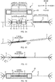
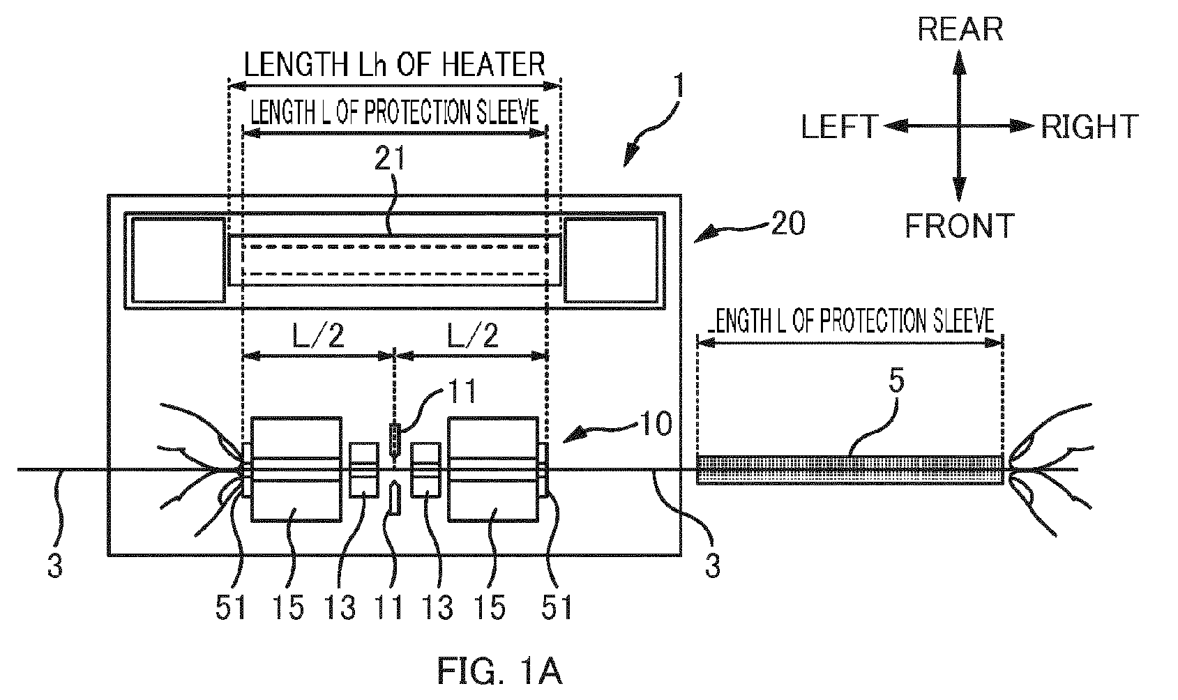
- FIG. 1A to FIG. 1D are explanatory views of an alignment method of a first embodiment.
- a distance (L/2) between an aligning part 51 and a fusion splice point is set to a half of a length L (standard length) of the protection sleeve 5.
- a distance (L/2) between the aligning part 51 and the fusion splice point is equal to or less than a half of a length Lh of the heater 21 (Note that, a length Lh of the heater 21 is not an entire length of the heating part 20, and is a length of a section that becomes hot for heating the protection sleeve 5 in the heating part 20).
- an operator Before setting an optical fiber 3 to the fusion splicing device 1, an operator places in advance the protection sleeve 5 onto one optical fiber 3 of a pair of optical fibers 3 (here, optical fiber 3 to right side in drawing: first optical fiber) . Then, the operator performs a pretreatment to the optical fiber 3. In the pretreatment of the optical fiber 3, a coating in an end part of the optical fiber 3 is removed, and the optical fiber 3 is cut such that a glass part that has been removed of the coating becomes a predetermined length and the like.
- the operator sets each of the pair of optical fibers 3 that has been pretreated to the fusion splicing device 1. Specifically, at least a part of a coating of the optical fiber 3 on the right side in the drawing (first optical fiber) is clamped with a coating clamp part 15 to the right side (first coating clamp part), and a glass part removed of the coating is clamped with the glass clamp part 13 to the right side (first glass clamp part). Further, at least a part of the coating of the optical fiber 3 to the left side in the drawing (second optical fiber) is clamped with a coating clamp part 15 to the left side (second coating clamp part), and a glass part with the coating removed is clamped with the glass clamp part 13 to the right side (second glass clamp part) .
- the state shown in FIG. 1A shows a state immediately after the pair of optical fibers 3 have been fusion spliced.
- the operator makes the left hand fingers contact the aligning part 51 to align the fingertips, and holds the optical fiber 3 (second optical fiber) with two fingers.
- the fingertips that contact the aligning part 51 are aligned in a position in which a distance to the fusion splice point is a half of a length of the protection sleeve 5.
- the fingertips, aligned in a position in which a distance to the fusion splice point is a half of a length of the protection sleeve 5 hold the optical fiber 3 (second optical fiber).
- the operator while holding the optical fiber 3 with the two fingers of the left hand, removes the optical fibers 3 (first optical fiber and second optical fiber) after fusion splicing that are clamped, and takes out the optical fiber 3 from the fusion splicing part 10.
- the operator inclines the optical fiber 3 such that the left side is lowered, as shown in FIG. 1B , and makes the protection sleeve 5 placed onto the optical fiber 3 to the right side (first optical fiber) slide to the left side under its own weight. Then, the operator slides the protection sleeve 5 to the left side such that the left end of the protection sleeve 5 contacts the fingertips holding the optical fiber 3. When the protection sleeve 5 slides to the left side, the protection sleeve 5 is covered over the fusion splice point of the optical fibers 3.
- the left end of the protection sleeve 5 contacts the fingertips holding the optical fiber 3, and when the protection sleeve 5 cannot slide to the left side any more, the fusion splice point is positioned in the center of the protection sleeve 5.
- the fusion splice point and the center of the protection sleeve 5 are aligned, and the protection sleeve 5 can be covered on the fusion splice point.
- the fusion splice point and the center of the protection sleeve 5 can be aligned with an easy method in this embodiment, thus the alignment operation of the protection sleeve can be carried out efficiently.
- the operator returns the inclined optical fiber 3 to a horizontal state, as shown in FIG. 1C , and slides the fingertips of the left hand contacting the protection sleeve 5 to the left side along the optical fiber 3. In this way, a gap is made between the protection sleeve 5 and the fingertips of the left hand, thus the protection sleeve 5 can be easily set in the heater 21. It should be noted that, at this time, the position of the protection sleeve 5 in respect to the optical fiber 3 does not change, and the fusion splice point is positioned in the center of the protection sleeve 5.
- the operator sets the protection sleeve 5 in the heater 21, as shown in FIG. 1D .
- the operator sets the protection sleeve 5 in the heater 21, such that a gap between the end part of the protection sleeve 5 and the end part of the heater 21 is equal at both the left and the right. In this way, the center of the protection sleeve 5 and the center of the heater 21 are aligned.
- the heater 21 is slightly longer than the protection sleeve 5 (approximately a few mm), so that supposing the center of the protection sleeve 5 is shifted from the center of the heater 21, the gap between the end part of the protection sleeve 5 and the end part of the heater 21 to the left and the right become unequal such that it can be identified by visual inspection.
- the alignment between the center of the protection sleeve 5 and the center of the heater 21 will be carried out almost accurately.
- a mark showing a setting position of an end part of a protection sleeve 5, however, can be provided to the heater 21, and the end part of the protection sleeve 5 may be aligned to this mark, and the protection sleeve 5 may be set in the heater 21.
- FIG. 2A and FIG. 2B are top views of a fusion splicing device 1.
- FIG. 2A is a view showing a lid of the fusion splicing device 1 (wind protector cover 17 and heater cover 22) in a closed state.
- FIG. 2B is a view showing a lid of the fusion splicing device 1 in an open state.
- FIG. 3 is a perspective view of a fusion splicing part 10 in an upper surface of the device inside the wind protector cover 17.
- FIG. 4 is a schematic explanatory view of the fusion splicing part 10 and a heating part 20.
- each direction is defined as below.
- a longitudinal direction of an optical fiber 3 when fusion splicing is referred to as a "left-right direction”
- a right hand side of an operator when seen from an operator operating the fusion splicing device 1 is referred to as "right”
- an opposite side is referred to as "left”.
- a direction in which the pair of electrodes 11 are opposed is referred to as a “front-rear direction”
- the operator's side when seen from the electrode 11 is referred to as "front”
- an opposite side heatating part 20 side
- the front-rear direction is referred to as a "depth direction”
- the operator's side is referred to as “front side”
- the heating part 20 side is also referred to as "back”.
- a direction perpendicular to the left-right direction and the front-rear direction (or, a direction perpendicular to a mounting surface of the optical fiber 3 in the glass clamp part 13) is referred to as an "up-down direction”
- an upper side in a vertical direction is referred to as “up”
- an opposite side is referred to as "down”.
- the fusion splicing device 1 is a device that fusion splices a pair of optical fibers 3.
- the fusion splicing device 1, in this embodiment fusion splices a pair of single optical fibers 3, but may fusion splice a pair of optical fibers with multiple fibers (for example, a pair of optical fiber ribbons).
- the fusion splicing device 1 has a fusion splicing part 10, a heating part 20, an operation section 31, and a display section 32.
- the fusion splicing part 10 is a mechanism to fusion splice optical fibers 3.
- the fusion splicing part 10 has a pair of electrodes 11, a pair of glass clamp parts 13, a pair of coating clamp parts 15, and a wind protector cover 17.
- the pair of electrodes 11 is a connecting section to fusion splice a pair of optical fibers 3.
- the electrodes 11 are a discharge electrode bar.
- the pair of electrodes 11 (connecting section) fusion splices the pair of single optical fiber 3 in this embodiment, but may fusion splice a pair of optical fibers with multiple fibers (for example, a pair of optical fiber ribbons) .
- the pair of electrodes 11 generates an arc discharge to heat tip end parts of the optical fibers 3, the heated tip end parts of the optical fibers 3 melt, and the pair of optical fibers 3 are fusion spliced.
- the fusion splice point of the optical fibers 3 is positioned on a line connecting the pair of electrodes 11 (however, in the case where the optical fibers 3 and the electrodes 11 are misaligned in the up-down direction, the fusion splice point of the optical fibers 3 may become misaligned to a central position between the pair of electrodes 11 in the up-down direction).
- the position of the fusion splice point of the optical fibers 3 in the left-right direction is approximately the same as the position of the electrodes 11 in the left-right direction.
- the pair of electrodes 11 is provided to an upper surface of the device inside the wind protector cover 17.
- the glass clamp part 13 is a section to clamp a glass part (a section from which a coating of an optical fiber 3 has been removed) of an optical fiber 3.
- the glass clamp part 13 clamps a single optical fiber 3 in this embodiment, but may clamp a plurality of optical fibers (for example, optical fiber ribbon).
- the pair of glass clamp parts 13 (first glass clamp part and second glass clamp part) are provided to an outer side of the pair of electrodes 11 in the left-right direction.
- the glass clamp part 13 has a base part 13A with a V groove, and a press part 13B.
- the base part 13A (V groove) of the glass clamp part 13 is provided to an upper surface of the device inside the wind protector cover 17.
- the press part 13B is provided to an inner surface of the wind protector cover 17. When the wind protector cover 17 is closed, the glass part of the optical fiber 3 is clamped between the base part 13A (V groove) and the press part 13B.
- the coating clamp part 15 is a section to clamp at least a part of a coating of an optical fiber 3.
- the coating clamp part 15 clamps a single optical fiber 3 in this embodiment, but may clamp a plurality of optical fibers (for example, an optical fiber ribbon).
- a pair of coating clamp parts 15 (first coating clamp part and second coating clamp part) is provided to outer sides of the pair of glass clamp parts 13 in the left-right direction.
- one coating clamp part 15 is arranged further to the right side of the glass clamp part 13 in the right side of the drawing, and the other coating clamp part 15 is arranged further to the left side of the glass clamp part 13 to left side in the drawing.
- the coating clamp part 15 has a base part 15A with a V groove and a press part 15B.
- the press part 15B of the coating clamp part 15 is provided so as to be openable and closable in respect to the base part 15A, and when the press part 15B is closed, the coating of the optical fiber 3 is to be clamped between the base part 15A (V groove) and the press part 15B.
- the optical fiber 3 to be clamped with the coating clamp part 15 may be coated in all sections, or may partly be a glass part (a part to be uncovered of the coating may be clamped).
- the base part 15A and the press part 15B of the coating clamp part 15 are both provided to an upper surface of a device inside the wind protector cover 17.
- the coating clamp part 15 is mounted to the upper surface of the device.
- the coating clamp part 15 may be configured as a holder that can be attached or detached from the upper surface of the device.
- the operator clamps the optical fiber 3 in the coating clamp part 15 of the holder, and after pretreating the optical fiber 3, the holder clamping the optical fiber 3 is to be set to the upper surface of the device.
- the wind protector cover 17 is a member (cover) covering the fusion splicing part 10 (electrode 11, glass clamp part 13, and coating clamp part 15).
- the wind protector cover 17 is provided openable and closable in respect to the body of the device. When the wind protector cover 17 is closed, the fusion splicing part 10 is sealed. In this way, a stable discharge can be achieved, and fusion splicing of the optical fiber 3 can be normally carried out.
- An inner surface of the wind protector cover 17 is provided with the press part 13B of the glass clamp part 13.
- the aligning part 51 is provided to an upper surface of the device inside the wind protector cover 17.
- the aligning part 51 is a section at which fingertips holding an optical fiber 3 are aligned to a predetermined position. It should be noted that, as shown in FIG. 1A and FIG. 1B , the fingertips aligned with the aligning part 51 are contacted with the protection sleeve 5 that has been made to slide, to align the fusion splice point and the protection sleeve 5.
- the aligning part 51 is a section at which the fingertips contacted with the protection sleeve 5 are aligned in a predetermined position in respect to fusion splice point.
- the aligning part 51 is provided to a side surface to an outer side of the coating clamp part 15. This aligning part 51 will be described later.
- the heating part 20 is a mechanism to heat the protection sleeve 5.
- the heating part 20 has the heater 21 and the heater cover 22.
- the heater 21 is a section that becomes very hot to heat the protection sleeve 5.
- the heater 21 has a mounting plane to mount the protection sleeve 5, and when heating, this mounting plane becomes very hot.
- the heater 21 has a hottest temperature at the center in the left-right direction, and the temperature gradient is such that the temperature gradually lowers from the center to end part.
- FIG. 5 is a schematic block diagram of the protection sleeve 5.
- the protection sleeve 5 is a reinforcing member to protect the fusion splice point and the glass part.
- the protection sleeve 5 is configured with a heat-shrinkable tube.
- the protection sleeve 5 has an outer tube 5A, a tension member 5B, and a hot-melt adhesive 5C.
- the outer tube 5A is configured from a heat-shrinkable tube, and is a member that forms the hot-melt adhesive 5C.
- An inner side of the outer tube 5A houses the tension member 5B and the hot-melt adhesive 5C.
- the tension member 5B is a member that reinforces against pulling and bending.
- the tension member 5B for example, is configured with a metal such as stainless steel, or glass-ceramics. It should be noted that, the length of the tension member 5B does not have to be the same as length L of the protection sleeve 5, and can be shorter than length L.
- the hot-melt adhesive 5C is a member to protect the fusion splice point and to bond the tension member 5B.
- the hot-melt adhesive 5C is configured from resin that melts when heating.
- the hot-melt adhesive 5C may be referred to as an inner tube.
- the hot-melt adhesive 5C is formed with an insertion hole to insert the optical fiber 3 through.
- the protection sleeve 5 is heated with the optical fiber 3 inserted through this insertion hole, and in this way the fusion splice point and the glass part of the optical fiber 3 is protected. It should be noted that, the configuration of the protection sleeve 5 is not limited to the above.
- the protection sleeve 5 with a length of 60 mm is generally used (a protection sleeve with a length of 40 mm is also available, but 90% of the protection sleeves distributed in the market are protection sleeves with a length of 60 mm).
- use of a standard protection sleeve with a length of 60 mm is assumed.
- An actual length of a standard protection sleeve with a length of 60 mm is in a range of equal to or greater than 60 mm to equal to or less than 62 mm.
- a "longest length of protection sleeve” refers to "62 mm”.
- "a standard length of a protection sleeve” refers to a range of "equal to or greater than 60 mm to equal to or less than 62 mm”.
- the heater 21 in this embodiment is formed longer than the protection sleeve 5 in the left-right direction. Specifically, a length Lh of the heater 21 in the left-right direction is set in a range of equal to or greater than 64 mm to equal to or less than 68 mm. It should be noted that, when the length Lh of the heater 21 in the left-right direction is equal to or greater than 64 mm, a margin of equal to or greater than 1 mm can be provided to the left and right, and the protection sleeve 5 with a longest length of 62 mm can be set to the heater 21.
- the length Lh of the heater 21 when the length Lh of the heater 21 is less than 64 mm, in setting the protection sleeve 5 with a longest length of 62 mm to the heater 21, the margin becomes less than 1 mm to the left and the right, thus setting the protection sleeve 5 to the heater 21 becomes difficult.
- the length Lh of the heater 21 is over 68 mm, in a case where the center of the protection sleeve 5 with a length of 60 mm is misaligned with respect to the center of the heater 21, a difference in a gap to the left and right of the end part of the protection sleeve 5 and the end part of the heater 21 cannot be easily visually recognized.
- the length of the heater 21 in the left-right direction is preferably in a range of equal to or greater than 64 mm to equal to or less than 68 mm.
- the operation section 31 is a section where the operator carries out operations of the fusion splicing device 1.
- the operation section 31 has various buttons.
- the operation section 31, however, is not limited to buttons, and may be for example, a dial.
- the display section 32 is a section (display) to display various kinds of information. The operator operates the operation section 31 while looking at the information displayed on the display section 32. It should be noted that, the display section 32 and the operation section 31 can be integrally configured with a touch panel.
- a distance between the aligning part 51 and the fusion splice point is a half of a standard length of the protection sleeve 5 (equal to or greater than 60 mm to equal to or less than 62 mm).
- the distance between the aligning part 51 and the fusion splice point is equal to or less than a half of a length of the longest protection sleeve 5 (62 mm) .
- the distance between the aligning part 51 and the fusion splice point is set to 30 mm. In this way, as shown in FIG.
- the fingertips will be aligned in a position in which a distance to the fusion splice point is a half of a length of the protection sleeve 5.
- the length of the heater 21 is set in a range of equal to or greater than 64 mm to equal to or less than 68 mm, the distance between the aligning part 51 and the fusion splice point is equal to or less than a half of the length of the heater 21.
- FIG. 6A is a perspective view of the left side coating clamp part 15 and the aligning part 51.
- FIG. 6B is an explanatory view showing holding of an optical fiber 3 with two fingers of a left hand.
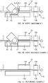
- FIG. 7A is a schematic explanatory view when viewing a periphery of the aligning part 51 of the first embodiment from the front. It should be noted that, FIG. 7C is a schematic explanatory view of a reference example that does not have an aligning part 51.
- the aligning part 51 is provided to a side surface to an outer side of the coating clamp part 15 to an upper surface of the device inside the wind protector cover 17.
- the operator aligns fingertips by making fingers of the left hand contact the aligning part 51, and holding the optical fiber 3 with two fingers.
- the aligning part 51 is formed as a plate-form section formed to a side surface to an outer side of the coating clamp part 15.
- the aligning part 51 has a perpendicular surface (a surface perpendicular to the optical fiber 3 clamped with the coating clamp part 15) in the left-right direction.
- the fingertips are aligned by making the fingertips contact a plate surface of the plate-form aligning part 51.
- the side surface to the outer side of the aligning part 51 becomes a reference position to align the fingertips.
- the aligning part 51 is formed to each side surface to an outer side of each of a pair of coating clamp parts 15.
- the fusion splicing device 1 in this embodiment is provided with a pair of the aligning parts 51.
- the operator can not only align fingertips of a left hand using the left side aligning part 51, but can also align fingertips of a right hand using the right side aligning part 51, thus can hold the optical fiber 3 (second optical fiber) with either the left or the right hand and so is convenient.
- the aligning part 51 does not have to be provided to both the left and right, as long as the aligning part 51 is provided to at least either the left or the right.
- the aligning part 51 is formed in a plate-form to extend from a base part 15A of the coating clamp part 15 to the upper side (press part 15B side) .
- this plate-form aligning part 51 is arranged to cover a part of a side surface of the press part 15B from the outer side. In this way, when the fingertips are made to contact the aligning part 51, the fingertips do not easily contact the press part 15B. As a result, when the operator removes the optical fiber 3 from the coating clamp part 15 with the two fingers of the left hand holding the optical fiber 3, the press part 15B can be easily opened.
- the plate-form aligning part 51 is formed in a U-shape.
- the aligning part 51 has a pair of plate parts 51A extending to the upper side to cover a part of a side surface of the press part 15B from the outer side, and a recessed fiber insertion part 51B formed between the pair of plate parts 51A.
- the pair of plate parts 51A are arranged aligned in the front-rear direction (depth direction) sandwiching the fiber insertion part 51B.
- the fingertip of the thumb is made to contact the plate part 51A to the front side (front)
- the fingertip of the index finger is made to contact the plate part 51A to the rear side (back side)
- the optical fiber 3 inserted in the fiber insertion part 51B can be easily held between the thumb and the index finger.
- a recessed part 52 is formed to an outer side of the aligning part 51.
- the recessed part 52 is a section recessed to a lower side than the optical fiber 3 extending to an outer side from the coating clamp part 15 (or aligning part 51).
- a part of the fingers holding the optical fiber 3 can be placed in to the lower side than the optical fiber 3.
- the optical fiber 3 can be held near the section of the fingertips contacting the aligning part 51.
- the section of the fingertips contacting the aligning part 51 and the section of the fingertips holding the optical fiber 3 can be brought close to each other. In this way, the operation of holding the optical fiber 3 while aligning the fingertips becomes easy.
- the recessed part 52 is a section into which part of the fingers are placed in to the lower side than the optical fiber 3, and the optical fiber 3 can be easily held.
- the depth of the recessed part 52 is preferably equal to or greater than 2 mm.
- the recessed part 52 is recessed by equal to or greater than 2 mm from an upper surface (a surface formed with a V groove) of the base part 15A of the coating clamp part 15.
- a step part equal to or greater than 2 mm is formed between an upper surface of the base part 15A of the coating clamp part 15 and a bottom surface of the recessed part 52.
- the depth of the recessed part 52 is smaller than 2 mm, part of the fingers cannot be easily placed in to the lower side than the optical fiber 3 (however, when the depth of the recessed part 52 is smaller than 2 mm, compared to a configuration without the recessed part 52, the optical fiber 3 is in a state in which it can be easily held).
- the recessed part 52 is preferably formed along the front-rear direction. In this way, the optical fiber 3 can be easily held with two fingertips in the front-rear direction while a part of the fingers are placed in to the lower side than the optical fiber 3. Specifically, the size of the recessed part 52 in the front-rear direction is preferably equal to or greater than 15 mm.
- a fiber support section 54 is formed to an outer side of the recessed part 52.
- the fiber support section 54 is a section that supports the optical fiber 3 in an opposite side of the coating clamp part 15 when seen from the recessed part 52 (or aligning part 51).
- the section of the fiber support section 54 that supports the optical fiber 3 is positioned to an upper side than the bottom surface of the recessed part 52, and here, is approximately the same height as an upper surface of the base part 15A of the coating clamp part 15.
- FIG. 7B is an explanatory view of a first modified example.
- the aligning part 51 does not cover a part of a side surface of press part 15B from the outer side, but is configured with a side surface of the base part 15A and a side surface of the press part 15B.
- the fingertips contact the aligning part 51
- the fingertips contact the press part 15B.
- the press part 15B cannot be easily opened.
- the optical fiber 3 can be held with two fingers, while aligning the fingertips by making fingers of the left hand contact the aligning part 51.
- the recessed part 52 is formed to an outer side of the aligning part 51, part of the fingers holding the optical fiber 3 can be placed in to the lower side than the optical fiber 3, and the operation of holding the optical fiber 3 while aligning the fingertips becomes easy.
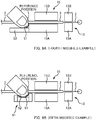
- FIG. 8A is an explanatory view of a second modified example.
- the aligning part 51 instead of the aligning part 51 being formed to extend to the upper side from the base part 15A of the coating clamp part 15, the aligning part 51 is formed to extend to the upper side from the bottom surface of the recessed part 52 arranged to an outer side of the coating clamp part 15.
- FIG. 8B is an explanatory view of a third modified example.
- an aligning part 51 is provided to a guide part 61 independent from a coating clamp part 15.
- the guide part 61 has the aligning part 51 and a recessed part 52 (and a fiber support section 54).
- an optical fiber 3 can be held with two fingers, while aligning fingertips by making fingers of a left hand contact the aligning part 51.
- the recessed part 52 is formed to an outer side of the aligning part 51, part of the fingers holding the optical fiber 3 can be placed in to the lower side than the optical fiber 3, and the operation of holding the optical fiber 3 while aligning the fingertips becomes easy.
- the width of the coating clamp part 15 in the left-right direction needs to be shortened. Even if the width of the coating clamp part 15 in the left-right direction is shortened, however, as long as a force to clamps the optical fiber 3 can be sufficiently ensured, as in the second modified example and the third modified example, the aligning part 51 can be arranged apart from the coating clamp part 15, to an outer side of the coating clamp part 15.
- FIG. 9A is an explanatory view of a fourth modified example.
- the aligning part 51 has a recessed curved surface.
- the recessed curved surface is formed to a lower side of the optical fiber 3 extending from the coating clamp part 15 (or aligning part 51).
- the recessed curved surface is configured as a curved surface with a curvature of a degree such that it fits the shape of fingertips.
- the operator can fit fingertips to the recessed curved surface, so that the position of the fingertips can be easily fitted to the aligning part 51.
- a section closest to the optical fiber 3 of the recessed curved surface becomes the reference position, and in this reference position, the distance between the aligning part 51 and the fusion splice point is set to be a half of the length of the protection sleeve 5 (for example, 30 mm).
- the fingertips contacting the aligning part 51 can be aligned in a position such that the distance to the fusion splice point is a half of the length of the protection sleeve 5.
- the protection sleeve 5 when the protection sleeve 5 is made to slide to contact the fingertips (refer to FIG. 1B ), the protection sleeve 5 can be covered on the fusion splice point, while the fusion splice point and the center of the protection sleeve 5 are aligned.
- FIG. 9B is an explanatory view of a fifth modified example.
- an aligning part 51 is provided to a guide part 61 independent from a coating clamp part 15.
- an aligning part 51 having a recessed curved surface is provided, to the guide part 61.
- a curved surface is also formed in a bottom surface of the recessed part 52.
- a section closest to the optical fiber 3 of the recessed curved surface becomes a reference position, and in this reference position, a distance between the aligning part 51 and the fusion splice point is set to be a half of the length of the protection sleeve 5 (for example, 30 mm). In this way, fingertips that have contacted the aligning part 51 can be aligned to a position in which a distance to the fusion splice point is a half of the length of the protection sleeve 5.
- the optical fiber 3 can be held with two finger, while aligning fingertips by making fingers of a left hand contact the aligning part 51.
- the recessed part 52 is formed to the outer side of the aligning part 51, part of fingers holding the optical fiber 3 can be placed in to the lower side than the optical fiber 3, and the operation to hold the optical fiber 3 while aligning the fingertips can be made easy.
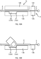
- FIG. 10A and FIG. 10B are explanatory views of a second embodiment.
- FIG. 10A is an explanatory view of a coating clamp part 15 and a glass clamp part 13 clamping an optical fiber 3.
- FIG. 10B is an explanatory view of fingertips holding the optical fiber 3 (when removing the clamped optical fiber 3).
- the aligning part 51 is provided to an inner side of the coating clamp part 15 to an upper surface of the device inside a wind protector cover 17.
- the aligning part 51 is provided on an upper surface of the base part 15A that opposes the press part 15B of the coating clamp part 15.
- the aligning part 51 is not limited to that provided to an outer side of the coating clamp part 15 as in the first embodiment, and may be provided to an inner side (upper surface of base part 15A) of the coating clamp part 15.
- the recessed part 52 to an outer side of the aligning part 51 is also preferably provided to an inner side of the coating clamp part 15 (upper surface of base part 15A).
- the operator After fusion splicing, the operator first opens the wind protector cover 17. In this way, a press part 13B of a glass clamp part 13 provided to the wind protector cover 17 is removed, to show the glass part of the optical fiber 3.
- the operator opens the press part 15B of the coating clamp part 15 to the left side, while the optical fiber 3 (first optical fiber) is clamped in the right side coating clamp (not shown) without opening the right side coating clamp part 15 (not shown).
- the operator contacts finger of the left hand to the aligning part 51, as shown in FIG. 10B , to align fingertips, and hold the optical fiber 3 (second optical fiber) with two fingers.
- the fingertips contacting the aligning part 51 have been aligned in a position such that a distance to the fusion splice point is a half of the length of the protection sleeve 5.
- the optical fiber 3 (second optical fiber) is held with fingertips aligned to a position in which the distance to the fusion splice point is a half of the length of the protection sleeve 5.
- the operator opens the press part 15B of a right side coating clamp part 15 (not shown), with the optical fiber 3 being held with the two fingers of the left hand.
- the clamped fusion spliced optical fiber 3 (first optical fiber and second optical fiber) is removed, so that the optical fiber 3 can be taken out from the fusion splicing part 10.
- the operation after taking out the optical fiber 3 is similar to that of the above-described embodiment (refer to FIG. 1B to FIG. 1D ).
- the width of the coating clamp part 15 has to be made relatively short in the left-right direction.
- the aligning part 51 is provided to an outer side of the coating clamp part 15 as in the above-described first embodiment, the width of the coating clamp part 15 has to be made relatively short in the left-right direction.
- the second embodiment by providing the aligning part 51 to an inner side of the coating clamp part 15, there is an advantage that the width of the coating clamp part 15 in the left-right direction can be set to be wide. As a result, in the second embodiment, the coating clamp part 15 can be easily designed such that a force to clamp the optical fiber 3 can be sufficiently ensured.
- the coating clamp part 15 may be configured as a holder that is attachable and detachable to/from an upper surface of a device.
- the aligning part 51 and the recessed part 52 are to be formed to an inner side (upper surface of base part 15A) of the coating clamp part 15 that is a holder.
- FIG. 11 is an explanatory view of a third embodiment.
- a recessed part 52 is not formed to an outer side of an aligning part 51, which is different from in the above-described first embodiment and second embodiment.
- an aligning part 51 is provided to an outer side of a coating clamp part 15 to an upper surface of a device inside a wind protector cover 17.
- an optical fiber 3 can be held with two fingers while aligning fingertips by making fingers of a left hand contact the aligning part 51.
- a section in which a fiber support section 54 supports the optical fiber 3 is in a higher position than an upper surface of a base part 15A of the coating clamp part 15.
- the height of the fiber support section 54 can be made to vary in the up-down direction. In this way, easiness to hold the optical fiber 3 with two fingers can be adjusted.
- a fusion splicing device 1 in the first embodiment to the third embodiment described above has an electrode 11 (connecting section) that fusion splices a pair of optical fibers 3, a glass clamp part 13 provided to an outer side of the electrode 11, a coating clamp part provided to an outer side of the glass clamp part 13, a wind protector cover 17, a heater 21 that heats a protection sleeve, and an aligning part 51 that can align fingertips holding an optical fiber 3.
- the aligning part 51 is provided to an upper surface of a device inside the wind protector cover 17 in all the embodiments, and in the first embodiment and the second embodiment is provided to an outer side of the coating clamp part 15, and in the third embodiment the aligning part 51 is provided to an inner side of the coating clamp part 15.
- the distance between the aligning part 51 and the fusion splice point is equal to or less than a half of a length Lh of the heater 21. Because the length Lh of the heater 21 is longer than length L of the protection sleeve 5, when the distance between the aligning part 51 and the fusion splice point is made equal to or less than a half of the length Lh of the heater 21, when aligning as shown in FIG. 1A to FIG. 1D , the fusion splice point and the center of the protection sleeve can be aligned to the center of the heater 21, and the alignment operation (refer to FIG. 1A to FIG. 1D ) of the protection sleeve can be carried out efficiently.
- the distance between the aligning part 51 and the fusion splice point is greater than a half of the length of the heater 21, when aligning of the protection sleeve 5 is carried out as in FIG. 1B the positional relation of the fusion splice point and the center of the protection sleeve 5 becomes misaligned, and when the protection sleeve 5 is set in the heater 21 as in FIG. 1D the positional relation between the center of the protection sleeve 5 and the center of the heater 21 becomes misaligned.
- the distance between the aligning part 51 and the fusion splice point is preferably equal to or less than a half of the length Lh of the heater 21. Specifically, because the longest length Lh of the heater 21 is 68 mm, the distance between the aligning part 51 and the fusion splice point is preferably equal to or less than 34 mm.
- the distance between the aligning part 51 and the fusion splice point is equal to or less than a half of the length of the longest protection sleeve covered on the fusion splice.
- the distance between the aligning part 51 and the fusion splice point is preferably equal to or less than 31 mm.
- misalignment of the positional relation of the fusion splice point and the center of the protection sleeve 5 is allowable in a range of an error (2 mm) between the standard length (equal to or greater than 60 mm and equal to or less than 62 mm) of the protection sleeve 5 and the longest length of the protection sleeve 5 (62 mm), thus a lower limit of the distance between the aligning part 51 and the fusion splice point is preferably a value (58 mm) obtained by subtracting an error (2 mm) from the standard length (60 mm).
- the distance between the aligning part 51 and the fusion splice point is preferably equal to or greater than 58 mm (equal to or greater than a value obtained by subtracting an error of 2 mm from a standard length of 60 mm), and is equal to or less than 62 mm (equal to or less than a length of a longest protection sleeve 5).
- the distance between the aligning part 51 and the fusion splice point is preferably a half of a standard length of a protection sleeve to be covered onto the fusion splice point (equal to or greater than 60 mm and equal to or less than 62 mm).
- the distance between the aligning part 51 and the fusion splice point is preferably in a range of equal to or greater than 30 mm to equal to or less than 31 mm.
- the aligning part is formed to cover a part of the side surface of the press part 15B of the coating clamp part 15. In this way, when the fingertips are contacted to the aligning part 51, the fingertips do not easily contact the press part 15B, thus the press part 15B can be easily opened when removing the optical fiber 3 from the coating clamp part 15 with the optical fiber 3 in the held state.
- the aligning part 51 has the pair of plate parts 51A extending to the upper side from the base part 15A, and a fiber insertion part 51B that is recessed formed between the pair of plate parts 51A.
- a fingertip of a thumb is contacted to one plate part 51A
- a fingertip of an index finger is contacted to another plate part 51A, such that the optical fiber 3 inserted through the fiber insertion part 51B can be easily held between the thumb and the index finger.
- the recessed part 52 is formed to an outer side of the aligning part 51. In this way, the operation to hold the optical fiber 3 while aligning the fingertips becomes easy.
- the depth of the recessed part 52 described above is equal to or greater than 2 mm. In this way, a part of the finger can be easily placed in to the lower side than the optical fiber 3, and the optical fiber 3 can be easily held.
- the aligning part 51 is provided to the upper surface of the base part 15A that opposes the press part 15B of the coating clamp part 15. Because there is a restriction to set a distance between the aligning part 51 and the fusion splice point to a half of a length of the protection sleeve 5, by providing the aligning part 51 to an inner side of the coating clamp part 15, the width of the coating clamp part 15 in the left-right direction can be set to be wide.
- the aligning part 51 has a curved surface that is recessed, and the recessed curved surface is formed to the lower side of the optical fiber 3 extending from the coating clamp part 15. In this way, because fingertips can be fitted to the recessed curved surface, the position of the fingertips can be easily aligned with the aligning part 51.
- the operator before setting the optical fiber 3 in the fusion splicing device 1, the operator places the protection sleeve 5 in advance onto one of the optical fibers 3 (first optical fiber) of the pair of optical fibers 3. Then, the operator sets each one of the pair of optical fibers 3 to the fusion splicing device 1.
- the coating clamp part 15 first coating clamp part
- a glass part removed of the coating is clamped with one of the glass clamp part 13 (first glass clamp part)
- at least a part of the coating of another optical fiber 3 (second optical fiber) is clamped with the other coating clamp part 15 (second coating clamp part)
- a glass part removed of the coating is clamped with the other glass clamp part 13 (second glass clamp part).
- the operator after fusion splicing, the operator removes the clamped optical fibers 3 (first optical fiber and second optical fiber), with fingertips aligned to a position in which a distance to a fusion splice point is a half of a length of the protection sleeve 5 holding the other optical fiber 3 (second optical fiber). Then, as shown in FIG. 1B , the operator slides the protection sleeve placed onto one of the optical fibers 3 (first optical fiber) to contact the fingertips holding the other optical fiber 3 (second optical fiber), to cover the protection sleeve on the fusion splice point. With such an optical fiber 3 reinforcing method, the alignment operation of the protection sleeve (operation of aligning the fusion splice point and center of the protection sleeve 5) can be efficiently carried out.
Landscapes
- Physics & Mathematics (AREA)
- Engineering & Computer Science (AREA)
- Plasma & Fusion (AREA)
- General Physics & Mathematics (AREA)
- Optics & Photonics (AREA)
- Mechanical Coupling Of Light Guides (AREA)
Abstract


Description
- The present invention relates to a fusion splicing device and an optical fiber reinforcing method.
-
Patent Literature 1 discloses a fusion splicer that fusions and connects optical fibers.Patent Literature 1 discloses covering a protection sleeve (heat-shrinkable tube) on a fusion splice point, heating the protection sleeve with a heater (heating part) of the fusion splicer, and reinforcing the fusion splice point. - Patent Literature 1: Japanese Patent No.
4141891 - When heating a protection sleeve with a heater, it is necessary to (1) align a fusion splice point and a center of the protection sleeve, and (2) align the center of the protection sleeve and a center of the heater. These points will be described below.
-
FIG. 12A is an explanatory view of a positional relation between a fusion splice point and aprotection sleeve 5. As shown in the diagram, an operator needs to align a fusion splice point and a center of theprotection sleeve 5 when covering theprotection sleeve 5 on the fusion splice point. In this way, when coatings of a pair ofoptical fibers 3 are removed such that a lead-out length L1 is shorter than a half of a length L2 of theprotection sleeve 5, ends of theprotection sleeve 5 and the coating of theoptical fiber 3 can be overlapped. Supposing that the fusion splice point and the center of theprotection sleeve 5 are misaligned, there is a possibility that the protection sleeve 5 and the coating of theoptical fiber 3 cannot be overlapped, a portion that has been removed of the coating is exposed outside theprotection sleeve 5, and strength of theoptical fiber 3 cannot be maintained. -
FIG. 12B is an explanatory view of a positional relation between a center of theprotection sleeve 5 and a center of aheater 21. Theheater 21 is formed such that the temperature at a center of the heater 21 (a section that is made to have a high temperature to heat the protection sleeve 5) in the longitudinal direction (left-right direction) is the highest, and the temperature gradient is such that the temperature gradually lowers from the center to end portions. The heater is configured as above to discharge air inside theprotection sleeve 5 outside when being heated and shrinks, and to suppress bubbles from forming inside theprotection sleeve 5. Suppose that a positional relation of the center of theprotection sleeve 5 and the center of theheater 21 are misaligned, there is a possibility that a section that has not shrunk remains in one side of theprotection sleeve 5. -
Patent Literature 1 discloses that an operator tilts anoptical fiber 3 that has been fusion spliced, makes theprotection sleeve 5 that has been passed through with theoptical fiber 3 slide with its own weight, and align the position of theprotection sleeve 5 with respect to the fusion splice point, as shown inFIG. 13A - FIG. 13C . But with such an aligning method based on such visual checking, there is a possibility that the fusion splice point and the center of theprotection sleeve 5 will become misaligned.Patent Literature 1 adopts the following alignment method. -
FIG. 14 is an explanatory view of a configuration of a fusion splicing device disclosed inPatent Literature 1. This fusion splicing device is designed such that a total length 2B of a heating device 20' and a total length 2A of afusion splicing part 10 are equal. This fusion splicing device is designed such that a distance A between a fusion splice point and aguide 91 to thefusion splicing part 10 side is equal to a distance B between the center of theheater 21 and aguide 93 to the heating device 20' side. A protection sleeve mount is provided with aguide part 92 to which an end face of theprotection sleeve 5 is contacted. The position of theguide part 92 is adjusted such that a distance (L/2) between the center of theheater 21 and the end face of theguide part 92 becomes less than a half of a length L of theprotection sleeve 5. After an operator has fusion spliced a pair ofoptical fibers 3, as shown in the diagram, the operator holds theoptical fiber 3 with two fingers while contacting theguide 91 with the fingers, and takes out theoptical fiber 3 from thefusion splicing part 10. -
FIG. 15A to FIG. 15C are explanatory views of an alignment method using a fusion splicer ofFIG. 14 . When the operator has taken out theoptical fiber 3 from the fusion splicingpart 10, the operator makes an end face of theprotection sleeve 5 contact theguide part 92 of the protection sleeve mount, as shown inFIG. 15A . Then, the operator makes theoptical fiber 3 slide with respect to theprotection sleeve 5 until the fingers holding theoptical fiber 3 contact theguide 93 to the heating device 20' side, as shown inFIG. 15B . In this way, the fusion splice point and the center of theprotection sleeve 5 are aligned. Next, the operator sets theprotection sleeve 5 in theheater 21 while the fingers holding theoptical fiber 3 are contacted to theguide 93 to the heating device 20' side, as shown inFIG. 15C . In this way, the center of the protection sleeve 5 and the center of theheater 21 are aligned. - With the alignment method shown in
FIG. 15A to FIG. 15C , however, theprotection sleeve 5 is to be aligned at a third place (here protection sleeve mount) that is different from thefusion splicing part 10 and the heating device 20' . Thus, in this alignment method, the operator has to temporarily move the fusion splicedoptical fiber 3 from thefusion splicing part 10 to the third place (protection sleeve mount), align the fusion splice point and theprotection sleeve 5 in the third place, and then further move theoptical fiber 3 and theprotection sleeve 5 from the third place to the heating device 20', and an operation after fusion splicing is not efficient. - An objective of the present invention is to carry out an aligning operation of a protection sleeve efficiently.
- A main aspect of the invention to achieve the above objective is an optical fiber reinforcing method including:
- placing a protection sleeve in advance onto a first optical fiber before fusion splicing;
- clamping at least a part of a coating of the first optical fiber with a first coating clamp part, clamping a glass part that has been removed of a coating of the first optical fiber with a first glass clamp part, and clamping at least a part of a coating of a second optical fiber with a second coating clamp part, and clamping a glass part removed of a coating of the second optical fiber with a second glass clamp part;
- fusion splicing the first optical fiber and the second optical fiber that are being clamped;
- after the fusion splicing, removing the first optical fiber and the second optical fiber that have been clamped, while holding the second optical fiber with fingertips aligned to a position in which a distance to a fusion splice point is a half of the protection sleeve, the position being to an upper surface of a device inside a wind protector cover; and
- covering the protection sleeve onto the fusion splice point by sliding the protection sleeve placed onto the first optical fiber to contact the fingertips holding the second optical fiber.
- Other features of the present invention will be made clear by the following description with reference to the drawings. Advantageous Effects of Invention
- According to the present invention, an alignment operation of a protection sleeve can be efficiently carried out.
-
- [
FIG. 1] FIG. 1A to FIG. 1D are explanatory views of an alignment method of a first embodiment. - [
FIG. 2] FIG. 2A and FIG. 2B are top views of afusion splicing device 1. - [
FIG. 3] FIG. 3 is a perspective view of afusion splicing part 10 of an upper surface of a device inside awind protector cover 17. - [
FIG. 4] FIG. 4 is a schematic explanatory view of afusion splicing part 10 and aheating part 20. - [
FIG. 5] FIG. 5 is a schematic block diagram of aprotection sleeve 5. - [
FIG. 6] FIG. 6A is a perspective view of a left sidecoating clamp part 15 and an aligningpart 51.FIG. 6B is an explanatory view of a manner in which anoptical fiber 3 is held with two fingers of a left hand. - [
FIG. 7] FIG. 7A is a schematic explanatory view of a periphery of an aligningpart 51 of a first embodiment seen from the front.FIG. 7B is an explanatory view of a first modified example.FIG. 7C is a schematic explanatory view of a reference example without an aligningpart 51. - [
FIG. 8] FIG. 8A is an explanatory view of a second modified example.FIG. 8B is an explanatory view of a third modified example. - [
FIG. 9] FIG. 9A is an explanatory view of a fourth modified example.FIG. 9B is an explanatory view of a fifth modified example. - [
FIG. 10] FIG. 10A and FIG. 10B are explanatory views of a second embodiment. - [
FIG. 11] FIG. 11 is an explanatory view of a third embodiment. - [
FIG. 12] FIG. 12A is an explanatory view of a positional relation between a fusion splice point and aprotection sleeve 5.FIG. 12B is an explanatory view of a positional relation of a center of theprotection sleeve 5 and a center of aheater 21. - [
FIG. 13] FIG. 13A to FIG. 13C are explanatory views of a conventional alignment method. - [
FIG. 14] FIG. 14 is an explanatory view of a conventional fusion splicing device. - [
FIG. 15] FIG. 15A to FIG. 15C are explanatory views of an alignment method using a fusion splicer inFIG. 14 . - At least below matters will become clear from descriptions in this specification and attached drawings.
- A fusion splicing device will become clear including: a connecting section that fusion splices a pair of optical fibers; a glass clamp part to clamp a glass part that has been removed of a coating of the optical fiber, the glass clamp part being provided to an outer side of the connecting section; a coating clamp part to clamp at least a part of the coating of the optical fiber, the coating clamp part being provided to an outer side of the glass clamp part; a wind protector cover to cover the connecting section, the glass clamp part, and the coating clamp part; a heater to heat a protection sleeve covered on a fusion splice point of the optical fibers that have been fusion spliced with the connecting section; and an aligning part that can align fingertips holding the optical fiber, the aligning part being provided inside or to an outer side of the coating clamp part to an upper surface of a device inside the wind protector cover, wherein a distance between the aligning part and the fusion splice point is equal to or less than a half of a length of the heater. According to such a fusion splicing device, an alignment operation of a protection sleeve can be efficiently carried out.
- A distance between the aligning part and the fusion splice point is preferably equal to or less than 34 mm. This is because a longest length of a heater is 68 mm.
- A fusion splicing device will become clear including: a connecting section that fusion splices a pair of optical fibers; a glass clamp part to clamp a glass part that has been removed of a coating of the optical fiber, the glass clamp part being provided to an outer side of the connecting section; a coating clamp part to clamp at least a part of the coating of the optical fiber, the coating clamp part being provided to an outer side of the glass clamp part; a wind protector cover to cover the connecting section, the glass clamp part, and the coating clamp part; and an aligning part that can align fingertips holding the optical fiber, the aligning part being provided inside or to an outer side of the coating clamp part to an upper surface of a device inside the wind protector cover, wherein a distance between the aligning part and a fusion splice point is equal to or less than a half of a length of a longest protection sleeve to be covered on the fusion splice point. According to such a fusion splicing device, an alignment operation of a protection sleeve can be efficiently carried out.
- A distance between the aligning part and the fusion splice point is preferably equal to or less than 31 mm. This is because a longest length of a protection sleeve is 62 mm.
- A fusion splicing device will become clear including: a connecting section that fusion splices a pair of optical fibers; a glass clamp part to clamp a glass part that has been removed of a coating of the optical fiber, the glass clamp part being provided to an outer side of the connecting section; a coating clamp part to clamp at least a part of the coating of the optical fiber, the coating clamp part being provided to an outer side of the glass clamp part; a wind protector cover to cover the connecting section, the glass clamp part, and the coating clamp part; and an aligning part that can align fingertips holding the optical fiber, the aligning part being provided inside or to an outer side of the coating clamp part to an upper surface of a device inside the wind protector cover, wherein a distance between the aligning part and a fusion splice point is a half of a standard length of a protection sleeve to be covered on the fusion splice point. According to such a fusion splicing device, an alignment operation of a protection sleeve can be efficiently carried out.
- The coating clamp part preferably has a base part to mount the optical fiber, and a press part that is openable and closable in respect to the base part, and the aligning part is preferably formed to cover at least a part of a side surface to an outer side of the press part. In this way, a press part can be made so as to be easily opened.
- The aligning part preferably has a pair of plate parts extending to an upper side from the base part, and a fiber insertion part that is recessed and formed between the pair of the plate parts. In this way, an optical fiber can be easily held, while aligning the fingertips.
- A recessed part is preferably formed to an outer side of the aligning part. In this way, the operation of holding an optical fiber while aligning the fingertips becomes easy.
- A depth of the recessed part is preferably equal to or greater than 2 mm. In this way, a part of the finger can be easily placed in to a lower side than an optical fiber, and an optical fiber can be easily held.
- The coating clamp part preferably has a base part to mount the optical fiber, and a press part that is openable and closable in respect to the base part, and the aligning part is preferably formed to an upper surface of the base part that opposes the press part. In this way, the width of the coating clamp part can be set to be wide.
- The aligning part preferably has a curved surface that is recessed, and the curved surface is preferably formed to a lower side of the optical fiber extending from the coating clamp part. In this way, positions of the fingertips can be easily aligned with the aligning part.
- An optical fiber reinforcing method will become clear including: placing a protection sleeve in advance onto a first optical fiber before fusion splicing; clamping at least a part of a coating of the first optical fiber with a first coating clamp part, clamping a glass part that has been removed of a coating of the first optical fiber with a first glass clamp part, and clamping at least a part of a coating of a second optical fiber with a second coating clamp part, and clamping a glass part removed of a coating of the second optical fiber with a second glass clamp part; fusion splicing the first optical fiber and the second optical fiber that are being clamped; after the fusion splicing, removing the first optical fiber and the second optical fiber that have been clamped, while holding the second optical fiber with fingertips aligned to a position in which a distance to a fusion splice point is a half of the protection sleeve, the position being to an upper surface of a device inside a wind protector cover; and covering the protection sleeve onto the fusion splice point by sliding the protection sleeve placed onto the first optical fiber to contact the fingertips holding the second optical fiber. According to such an optical fiber reinforcing method, an aligning operation of a protection sleeve can be carried out efficiently.
- Before explaining a basic configuration of a
fusion splicing device 1, an alignment method of aprotection sleeve 5 will be described first. -
FIG. 1A to FIG. 1D are explanatory views of an alignment method of a first embodiment. In the present embodiment, a distance (L/2) between an aligningpart 51 and a fusion splice point is set to a half of a length L (standard length) of theprotection sleeve 5. It should be noted that, because a length Lh of aheater 21 is longer than a length L of theprotection sleeve 5, a distance (L/2) between the aligningpart 51 and the fusion splice point is equal to or less than a half of a length Lh of the heater 21 (Note that, a length Lh of theheater 21 is not an entire length of theheating part 20, and is a length of a section that becomes hot for heating theprotection sleeve 5 in the heating part 20). - Before setting an
optical fiber 3 to thefusion splicing device 1, an operator places in advance theprotection sleeve 5 onto oneoptical fiber 3 of a pair of optical fibers 3 (here,optical fiber 3 to right side in drawing: first optical fiber) . Then, the operator performs a pretreatment to theoptical fiber 3. In the pretreatment of theoptical fiber 3, a coating in an end part of theoptical fiber 3 is removed, and theoptical fiber 3 is cut such that a glass part that has been removed of the coating becomes a predetermined length and the like. - Next, the operator sets each of the pair of
optical fibers 3 that has been pretreated to thefusion splicing device 1. Specifically, at least a part of a coating of theoptical fiber 3 on the right side in the drawing (first optical fiber) is clamped with acoating clamp part 15 to the right side (first coating clamp part), and a glass part removed of the coating is clamped with theglass clamp part 13 to the right side (first glass clamp part). Further, at least a part of the coating of theoptical fiber 3 to the left side in the drawing (second optical fiber) is clamped with acoating clamp part 15 to the left side (second coating clamp part), and a glass part with the coating removed is clamped with theglass clamp part 13 to the right side (second glass clamp part) . Then, the operator operates thefusion splicing device 1, and fusion splices the pair ofoptical fibers 3 that are clamped. The state shown inFIG. 1A shows a state immediately after the pair ofoptical fibers 3 have been fusion spliced. - Next, as shown in
FIG. 1A , the operator makes the left hand fingers contact the aligningpart 51 to align the fingertips, and holds the optical fiber 3 (second optical fiber) with two fingers. At this time, the fingertips that contact the aligningpart 51 are aligned in a position in which a distance to the fusion splice point is a half of a length of theprotection sleeve 5. Further, at this time, the fingertips, aligned in a position in which a distance to the fusion splice point is a half of a length of theprotection sleeve 5, hold the optical fiber 3 (second optical fiber). Then, the operator, while holding theoptical fiber 3 with the two fingers of the left hand, removes the optical fibers 3 (first optical fiber and second optical fiber) after fusion splicing that are clamped, and takes out theoptical fiber 3 from thefusion splicing part 10. - Then, the operator inclines the
optical fiber 3 such that the left side is lowered, as shown inFIG. 1B , and makes theprotection sleeve 5 placed onto theoptical fiber 3 to the right side (first optical fiber) slide to the left side under its own weight. Then, the operator slides theprotection sleeve 5 to the left side such that the left end of theprotection sleeve 5 contacts the fingertips holding theoptical fiber 3. When theprotection sleeve 5 slides to the left side, theprotection sleeve 5 is covered over the fusion splice point of theoptical fibers 3. Then, the left end of theprotection sleeve 5 contacts the fingertips holding theoptical fiber 3, and when theprotection sleeve 5 cannot slide to the left side any more, the fusion splice point is positioned in the center of theprotection sleeve 5. In other words, by sliding theprotection sleeve 5 until it contacts the fingertips aligned with the aligning part 51 (fingertips holding second optical fiber), the fusion splice point and the center of theprotection sleeve 5 are aligned, and theprotection sleeve 5 can be covered on the fusion splice point. In this way, the fusion splice point and the center of theprotection sleeve 5 can be aligned with an easy method in this embodiment, thus the alignment operation of the protection sleeve can be carried out efficiently. - Then, the operator returns the inclined
optical fiber 3 to a horizontal state, as shown inFIG. 1C , and slides the fingertips of the left hand contacting theprotection sleeve 5 to the left side along theoptical fiber 3. In this way, a gap is made between theprotection sleeve 5 and the fingertips of the left hand, thus theprotection sleeve 5 can be easily set in theheater 21. It should be noted that, at this time, the position of theprotection sleeve 5 in respect to theoptical fiber 3 does not change, and the fusion splice point is positioned in the center of theprotection sleeve 5. - Then, the operator sets the
protection sleeve 5 in theheater 21, as shown inFIG. 1D . At this time, the operator sets theprotection sleeve 5 in theheater 21, such that a gap between the end part of theprotection sleeve 5 and the end part of theheater 21 is equal at both the left and the right. In this way, the center of theprotection sleeve 5 and the center of theheater 21 are aligned. It should be noted that, theheater 21 is slightly longer than the protection sleeve 5 (approximately a few mm), so that supposing the center of theprotection sleeve 5 is shifted from the center of theheater 21, the gap between the end part of theprotection sleeve 5 and the end part of theheater 21 to the left and the right become unequal such that it can be identified by visual inspection. Thus even when the operator sets theprotection sleeve 5 to theheater 21 by visual inspection, the alignment between the center of theprotection sleeve 5 and the center of theheater 21 will be carried out almost accurately. A mark showing a setting position of an end part of aprotection sleeve 5, however, can be provided to theheater 21, and the end part of theprotection sleeve 5 may be aligned to this mark, and theprotection sleeve 5 may be set in theheater 21. - Then, a configuration of a fusion splicing device appropriate for the above alignment method is explained.
-
FIG. 2A and FIG. 2B are top views of afusion splicing device 1.FIG. 2A is a view showing a lid of the fusion splicing device 1 (wind protector cover 17 and heater cover 22) in a closed state.FIG. 2B is a view showing a lid of thefusion splicing device 1 in an open state.FIG. 3 is a perspective view of afusion splicing part 10 in an upper surface of the device inside thewind protector cover 17.FIG. 4 is a schematic explanatory view of thefusion splicing part 10 and aheating part 20. - In the following explanation, each direction is defined as below. A longitudinal direction of an
optical fiber 3 when fusion splicing is referred to as a "left-right direction", a right hand side of an operator when seen from an operator operating thefusion splicing device 1 is referred to as "right", and an opposite side is referred to as "left". A direction in which the pair ofelectrodes 11 are opposed is referred to as a "front-rear direction", and the operator's side when seen from theelectrode 11 is referred to as "front", and an opposite side (heating part 20 side) is referred to as "rear". It should be noted that, the front-rear direction is referred to as a "depth direction", the operator's side is referred to as "front side", and theheating part 20 side is also referred to as "back". A direction perpendicular to the left-right direction and the front-rear direction (or, a direction perpendicular to a mounting surface of theoptical fiber 3 in the glass clamp part 13) is referred to as an "up-down direction", an upper side in a vertical direction is referred to as "up", and an opposite side is referred to as "down". - The
fusion splicing device 1 is a device that fusion splices a pair ofoptical fibers 3. Thefusion splicing device 1, in this embodiment fusion splices a pair of singleoptical fibers 3, but may fusion splice a pair of optical fibers with multiple fibers (for example, a pair of optical fiber ribbons). Thefusion splicing device 1 has afusion splicing part 10, aheating part 20, anoperation section 31, and adisplay section 32. - The
fusion splicing part 10 is a mechanism to fusion spliceoptical fibers 3. Thefusion splicing part 10 has a pair ofelectrodes 11, a pair ofglass clamp parts 13, a pair ofcoating clamp parts 15, and awind protector cover 17. - The pair of
electrodes 11 is a connecting section to fusion splice a pair ofoptical fibers 3. In other words, theelectrodes 11 are a discharge electrode bar. The pair of electrodes 11 (connecting section) fusion splices the pair of singleoptical fiber 3 in this embodiment, but may fusion splice a pair of optical fibers with multiple fibers (for example, a pair of optical fiber ribbons) . The pair ofelectrodes 11 generates an arc discharge to heat tip end parts of theoptical fibers 3, the heated tip end parts of theoptical fibers 3 melt, and the pair ofoptical fibers 3 are fusion spliced. When seen from above, the fusion splice point of theoptical fibers 3 is positioned on a line connecting the pair of electrodes 11 (however, in the case where theoptical fibers 3 and theelectrodes 11 are misaligned in the up-down direction, the fusion splice point of theoptical fibers 3 may become misaligned to a central position between the pair ofelectrodes 11 in the up-down direction). In other words, the position of the fusion splice point of theoptical fibers 3 in the left-right direction is approximately the same as the position of theelectrodes 11 in the left-right direction. The pair ofelectrodes 11 is provided to an upper surface of the device inside thewind protector cover 17. - The
glass clamp part 13 is a section to clamp a glass part (a section from which a coating of anoptical fiber 3 has been removed) of anoptical fiber 3. Theglass clamp part 13 clamps a singleoptical fiber 3 in this embodiment, but may clamp a plurality of optical fibers (for example, optical fiber ribbon). The pair of glass clamp parts 13 (first glass clamp part and second glass clamp part) are provided to an outer side of the pair ofelectrodes 11 in the left-right direction. Theglass clamp part 13 has abase part 13A with a V groove, and apress part 13B. Thebase part 13A (V groove) of theglass clamp part 13 is provided to an upper surface of the device inside thewind protector cover 17. Thepress part 13B is provided to an inner surface of thewind protector cover 17. When thewind protector cover 17 is closed, the glass part of theoptical fiber 3 is clamped between thebase part 13A (V groove) and thepress part 13B. - The
coating clamp part 15 is a section to clamp at least a part of a coating of anoptical fiber 3. Thecoating clamp part 15 clamps a singleoptical fiber 3 in this embodiment, but may clamp a plurality of optical fibers (for example, an optical fiber ribbon). A pair of coating clamp parts 15 (first coating clamp part and second coating clamp part) is provided to outer sides of the pair ofglass clamp parts 13 in the left-right direction. In other words, onecoating clamp part 15 is arranged further to the right side of theglass clamp part 13 in the right side of the drawing, and the othercoating clamp part 15 is arranged further to the left side of theglass clamp part 13 to left side in the drawing. Thecoating clamp part 15 has abase part 15A with a V groove and apress part 15B. Thepress part 15B of thecoating clamp part 15 is provided so as to be openable and closable in respect to thebase part 15A, and when thepress part 15B is closed, the coating of theoptical fiber 3 is to be clamped between thebase part 15A (V groove) and thepress part 15B. Theoptical fiber 3 to be clamped with thecoating clamp part 15 may be coated in all sections, or may partly be a glass part (a part to be uncovered of the coating may be clamped). Thebase part 15A and thepress part 15B of thecoating clamp part 15 are both provided to an upper surface of a device inside thewind protector cover 17. - In this embodiment, the
coating clamp part 15 is mounted to the upper surface of the device. However, thecoating clamp part 15 may be configured as a holder that can be attached or detached from the upper surface of the device. In this case, when setting anoptical fiber 3 in afusion splicing part 10, the operator clamps theoptical fiber 3 in thecoating clamp part 15 of the holder, and after pretreating theoptical fiber 3, the holder clamping theoptical fiber 3 is to be set to the upper surface of the device. - The
wind protector cover 17 is a member (cover) covering the fusion splicing part 10 (electrode 11,glass clamp part 13, and coating clamp part 15). Thewind protector cover 17 is provided openable and closable in respect to the body of the device. When thewind protector cover 17 is closed, thefusion splicing part 10 is sealed. In this way, a stable discharge can be achieved, and fusion splicing of theoptical fiber 3 can be normally carried out. An inner surface of thewind protector cover 17 is provided with thepress part 13B of theglass clamp part 13. - In this embodiment, the aligning
part 51 is provided to an upper surface of the device inside thewind protector cover 17. The aligningpart 51 is a section at which fingertips holding anoptical fiber 3 are aligned to a predetermined position. It should be noted that, as shown inFIG. 1A and FIG. 1B , the fingertips aligned with the aligningpart 51 are contacted with theprotection sleeve 5 that has been made to slide, to align the fusion splice point and theprotection sleeve 5. Thus, the aligningpart 51 is a section at which the fingertips contacted with theprotection sleeve 5 are aligned in a predetermined position in respect to fusion splice point. In this embodiment, the aligningpart 51 is provided to a side surface to an outer side of thecoating clamp part 15. This aligningpart 51 will be described later. - The
heating part 20 is a mechanism to heat theprotection sleeve 5. Theheating part 20 has theheater 21 and theheater cover 22. Theheater 21 is a section that becomes very hot to heat theprotection sleeve 5. Theheater 21 has a mounting plane to mount theprotection sleeve 5, and when heating, this mounting plane becomes very hot. Theheater 21 has a hottest temperature at the center in the left-right direction, and the temperature gradient is such that the temperature gradually lowers from the center to end part. -
FIG. 5 is a schematic block diagram of theprotection sleeve 5. - The
protection sleeve 5 is a reinforcing member to protect the fusion splice point and the glass part. Theprotection sleeve 5 is configured with a heat-shrinkable tube. Specifically, theprotection sleeve 5 has anouter tube 5A, atension member 5B, and a hot-melt adhesive 5C. Theouter tube 5A is configured from a heat-shrinkable tube, and is a member that forms the hot-melt adhesive 5C. An inner side of theouter tube 5A houses thetension member 5B and the hot-melt adhesive 5C. Thetension member 5B is a member that reinforces against pulling and bending. Thetension member 5B, for example, is configured with a metal such as stainless steel, or glass-ceramics. It should be noted that, the length of thetension member 5B does not have to be the same as length L of theprotection sleeve 5, and can be shorter than length L. The hot-melt adhesive 5C is a member to protect the fusion splice point and to bond thetension member 5B. The hot-melt adhesive 5C is configured from resin that melts when heating. The hot-melt adhesive 5C may be referred to as an inner tube. The hot-melt adhesive 5C is formed with an insertion hole to insert theoptical fiber 3 through. Theprotection sleeve 5 is heated with theoptical fiber 3 inserted through this insertion hole, and in this way the fusion splice point and the glass part of theoptical fiber 3 is protected. It should be noted that, the configuration of theprotection sleeve 5 is not limited to the above. - The
protection sleeve 5 with a length of 60 mm is generally used (a protection sleeve with a length of 40 mm is also available, but 90% of the protection sleeves distributed in the market are protection sleeves with a length of 60 mm). Thus, in this embodiment, use of a standard protection sleeve with a length of 60 mm is assumed. An actual length of a standard protection sleeve with a length of 60 mm is in a range of equal to or greater than 60 mm to equal to or less than 62 mm. In this embodiment, a "longest length of protection sleeve" refers to "62 mm". Further, in this embodiment, "a standard length of a protection sleeve" refers to a range of "equal to or greater than 60 mm to equal to or less than 62 mm". - The
heater 21 in this embodiment is formed longer than theprotection sleeve 5 in the left-right direction. Specifically, a length Lh of theheater 21 in the left-right direction is set in a range of equal to or greater than 64 mm to equal to or less than 68 mm. It should be noted that, when the length Lh of theheater 21 in the left-right direction is equal to or greater than 64 mm, a margin of equal to or greater than 1 mm can be provided to the left and right, and theprotection sleeve 5 with a longest length of 62 mm can be set to theheater 21. It should be noted that, when the length Lh of theheater 21 is less than 64 mm, in setting theprotection sleeve 5 with a longest length of 62 mm to theheater 21, the margin becomes less than 1 mm to the left and the right, thus setting theprotection sleeve 5 to theheater 21 becomes difficult. On the other hand, when the length Lh of theheater 21 is over 68 mm, in a case where the center of theprotection sleeve 5 with a length of 60 mm is misaligned with respect to the center of theheater 21, a difference in a gap to the left and right of the end part of theprotection sleeve 5 and the end part of theheater 21 cannot be easily visually recognized. Further, when the length Lh of theheater 21 is too long, heat capacity of theheater 21 becomes large, and it takes time for theheater 21 to reach a predetermined temperature, and this is not preferable. Thus, the length of theheater 21 in the left-right direction is preferably in a range of equal to or greater than 64 mm to equal to or less than 68 mm. - The
operation section 31 is a section where the operator carries out operations of thefusion splicing device 1. Here, theoperation section 31 has various buttons. Theoperation section 31, however, is not limited to buttons, and may be for example, a dial. Thedisplay section 32 is a section (display) to display various kinds of information. The operator operates theoperation section 31 while looking at the information displayed on thedisplay section 32. It should be noted that, thedisplay section 32 and theoperation section 31 can be integrally configured with a touch panel. - As shown in
FIG. 4 , a distance between the aligningpart 51 and the fusion splice point is a half of a standard length of the protection sleeve 5 (equal to or greater than 60 mm to equal to or less than 62 mm). In this embodiment, the distance between the aligningpart 51 and the fusion splice point is equal to or less than a half of a length of the longest protection sleeve 5 (62 mm) . Specifically, in this embodiment, the distance between the aligningpart 51 and the fusion splice point is set to 30 mm. In this way, as shown inFIG. 6B , when the operator makes fingers of a left hand contact the aligningpart 51, the fingertips will be aligned in a position in which a distance to the fusion splice point is a half of a length of theprotection sleeve 5. In this embodiment, because the length of theheater 21 is set in a range of equal to or greater than 64 mm to equal to or less than 68 mm, the distance between the aligningpart 51 and the fusion splice point is equal to or less than a half of the length of theheater 21. -
FIG. 6A is a perspective view of the left sidecoating clamp part 15 and the aligningpart 51.FIG. 6B is an explanatory view showing holding of anoptical fiber 3 with two fingers of a left hand.FIG. 7A is a schematic explanatory view when viewing a periphery of the aligningpart 51 of the first embodiment from the front. It should be noted that,FIG. 7C is a schematic explanatory view of a reference example that does not have an aligningpart 51. - As described already, in this embodiment, the aligning
part 51 is provided to a side surface to an outer side of thecoating clamp part 15 to an upper surface of the device inside thewind protector cover 17. In this embodiment, the operator aligns fingertips by making fingers of the left hand contact the aligningpart 51, and holding theoptical fiber 3 with two fingers. - The aligning
part 51 is formed as a plate-form section formed to a side surface to an outer side of thecoating clamp part 15. In this embodiment, the aligningpart 51 has a perpendicular surface (a surface perpendicular to theoptical fiber 3 clamped with the coating clamp part 15) in the left-right direction. The fingertips are aligned by making the fingertips contact a plate surface of the plate-form aligning part 51. In other words, the side surface to the outer side of the aligningpart 51 becomes a reference position to align the fingertips. - In this embodiment, the aligning
part 51 is formed to each side surface to an outer side of each of a pair ofcoating clamp parts 15. In other words, thefusion splicing device 1 in this embodiment is provided with a pair of the aligningparts 51. In this way, the operator can not only align fingertips of a left hand using the leftside aligning part 51, but can also align fingertips of a right hand using the rightside aligning part 51, thus can hold the optical fiber 3 (second optical fiber) with either the left or the right hand and so is convenient. The aligningpart 51, however, does not have to be provided to both the left and right, as long as the aligningpart 51 is provided to at least either the left or the right. - The aligning
part 51 is formed in a plate-form to extend from abase part 15A of thecoating clamp part 15 to the upper side (press part 15B side) . Thus, this plate-form aligning part 51 is arranged to cover a part of a side surface of thepress part 15B from the outer side. In this way, when the fingertips are made to contact the aligningpart 51, the fingertips do not easily contact thepress part 15B. As a result, when the operator removes theoptical fiber 3 from thecoating clamp part 15 with the two fingers of the left hand holding theoptical fiber 3, thepress part 15B can be easily opened. - The plate-
form aligning part 51 is formed in a U-shape. In other words, the aligningpart 51 has a pair ofplate parts 51A extending to the upper side to cover a part of a side surface of thepress part 15B from the outer side, and a recessedfiber insertion part 51B formed between the pair ofplate parts 51A. The pair ofplate parts 51A are arranged aligned in the front-rear direction (depth direction) sandwiching thefiber insertion part 51B. In this way, the fingertip of the thumb is made to contact theplate part 51A to the front side (front), the fingertip of the index finger is made to contact theplate part 51A to the rear side (back side), and theoptical fiber 3 inserted in thefiber insertion part 51B can be easily held between the thumb and the index finger. - In this embodiment, a recessed
part 52 is formed to an outer side of the aligningpart 51. The recessedpart 52 is a section recessed to a lower side than theoptical fiber 3 extending to an outer side from the coating clamp part 15 (or aligning part 51). With the recessedpart 52 being formed to an outer side of the aligningpart 51, a part of the fingers holding theoptical fiber 3 can be placed in to the lower side than theoptical fiber 3. In this way, theoptical fiber 3 can be held near the section of the fingertips contacting the aligningpart 51. In other words, by forming the recessedpart 52, the section of the fingertips contacting the aligningpart 51 and the section of the fingertips holding theoptical fiber 3 can be brought close to each other. In this way, the operation of holding theoptical fiber 3 while aligning the fingertips becomes easy. - As described above, the recessed
part 52 is a section into which part of the fingers are placed in to the lower side than theoptical fiber 3, and theoptical fiber 3 can be easily held. Thus, the depth of the recessedpart 52 is preferably equal to or greater than 2 mm. In this embodiment, the recessedpart 52 is recessed by equal to or greater than 2 mm from an upper surface (a surface formed with a V groove) of thebase part 15A of thecoating clamp part 15. In other words, when the recessedpart 52 is formed, a step part equal to or greater than 2 mm is formed between an upper surface of thebase part 15A of thecoating clamp part 15 and a bottom surface of the recessedpart 52. It should be noted that, when the depth of the recessedpart 52 is smaller than 2 mm, part of the fingers cannot be easily placed in to the lower side than the optical fiber 3 (however, when the depth of the recessedpart 52 is smaller than 2 mm, compared to a configuration without the recessedpart 52, theoptical fiber 3 is in a state in which it can be easily held). - The recessed
part 52 is preferably formed along the front-rear direction. In this way, theoptical fiber 3 can be easily held with two fingertips in the front-rear direction while a part of the fingers are placed in to the lower side than theoptical fiber 3. Specifically, the size of the recessedpart 52 in the front-rear direction is preferably equal to or greater than 15 mm. - In this embodiment, a
fiber support section 54 is formed to an outer side of the recessedpart 52. Thefiber support section 54 is a section that supports theoptical fiber 3 in an opposite side of thecoating clamp part 15 when seen from the recessed part 52 (or aligning part 51). The section of thefiber support section 54 that supports theoptical fiber 3 is positioned to an upper side than the bottom surface of the recessedpart 52, and here, is approximately the same height as an upper surface of thebase part 15A of thecoating clamp part 15. Thus, when theoptical fiber 3 is supported with thefiber support section 54 and thecoating clamp part 15, theoptical fiber 3 is in a state floating from the bottom surface of the recessedpart 52. In this way, the operator can easily hold theoptical fiber 3 with two fingers. -
FIG. 7B is an explanatory view of a first modified example. In the first modified example, the aligningpart 51 does not cover a part of a side surface ofpress part 15B from the outer side, but is configured with a side surface of thebase part 15A and a side surface of thepress part 15B. In the first modified example, when the fingertips contact the aligningpart 51, the fingertips contact thepress part 15B. As a result, in the first modified example, when the operator removes theoptical fiber 3 from thecoating clamp part 15 while holding theoptical fiber 3 with the two fingers of the left hand, thepress part 15B cannot be easily opened. When configuring the aligningpart 51 as in the first modified example however, theoptical fiber 3 can be held with two fingers, while aligning the fingertips by making fingers of the left hand contact the aligningpart 51. In also the first modified example, because the recessedpart 52 is formed to an outer side of the aligningpart 51, part of the fingers holding theoptical fiber 3 can be placed in to the lower side than theoptical fiber 3, and the operation of holding theoptical fiber 3 while aligning the fingertips becomes easy. -
FIG. 8A is an explanatory view of a second modified example. In the second modified example, instead of the aligningpart 51 being formed to extend to the upper side from thebase part 15A of thecoating clamp part 15, the aligningpart 51 is formed to extend to the upper side from the bottom surface of the recessedpart 52 arranged to an outer side of thecoating clamp part 15. -
FIG. 8B is an explanatory view of a third modified example. In the third modified example, an aligningpart 51 is provided to aguide part 61 independent from acoating clamp part 15. Theguide part 61 has the aligningpart 51 and a recessed part 52 (and a fiber support section 54). - In the second modified example and the third modified example, an
optical fiber 3 can be held with two fingers, while aligning fingertips by making fingers of a left hand contact the aligningpart 51. In also the second modified example and third modified example, because the recessedpart 52 is formed to an outer side of the aligningpart 51, part of the fingers holding theoptical fiber 3 can be placed in to the lower side than theoptical fiber 3, and the operation of holding theoptical fiber 3 while aligning the fingertips becomes easy. - It should be noted that, in this embodiment, because there is a restriction to set a distance between the aligning
part 51 and a fusion splice point to a half of the length of a protection sleeve 5 (for example, 30 mm), in the second modified example and the third modified example like this, the width of thecoating clamp part 15 in the left-right direction needs to be shortened. Even if the width of thecoating clamp part 15 in the left-right direction is shortened, however, as long as a force to clamps theoptical fiber 3 can be sufficiently ensured, as in the second modified example and the third modified example, the aligningpart 51 can be arranged apart from thecoating clamp part 15, to an outer side of thecoating clamp part 15. -
FIG. 9A is an explanatory view of a fourth modified example. In the fourth modified example, the aligningpart 51 has a recessed curved surface. The recessed curved surface is formed to a lower side of theoptical fiber 3 extending from the coating clamp part 15 (or aligning part 51). The recessed curved surface is configured as a curved surface with a curvature of a degree such that it fits the shape of fingertips. In the fourth modified example, the operator can fit fingertips to the recessed curved surface, so that the position of the fingertips can be easily fitted to the aligningpart 51. It should be noted that, in the fourth modified example, a section closest to theoptical fiber 3 of the recessed curved surface (section closest to the coating clamp part 15) becomes the reference position, and in this reference position, the distance between the aligningpart 51 and the fusion splice point is set to be a half of the length of the protection sleeve 5 (for example, 30 mm). In this way, the fingertips contacting the aligningpart 51 can be aligned in a position such that the distance to the fusion splice point is a half of the length of theprotection sleeve 5. In this way, when theprotection sleeve 5 is made to slide to contact the fingertips (refer toFIG. 1B ), theprotection sleeve 5 can be covered on the fusion splice point, while the fusion splice point and the center of theprotection sleeve 5 are aligned. -
FIG. 9B is an explanatory view of a fifth modified example. In the fifth modified example, similar to the third modified example, an aligningpart 51 is provided to aguide part 61 independent from acoating clamp part 15. In the fifth modified example, an aligningpart 51 having a recessed curved surface is provided, to theguide part 61. In the fifth modified example, a curved surface is also formed in a bottom surface of the recessedpart 52. It should be noted that, in the fifth modified example, a section closest to theoptical fiber 3 of the recessed curved surface (a section closest to the coating clamp part 15) becomes a reference position, and in this reference position, a distance between the aligningpart 51 and the fusion splice point is set to be a half of the length of the protection sleeve 5 (for example, 30 mm). In this way, fingertips that have contacted the aligningpart 51 can be aligned to a position in which a distance to the fusion splice point is a half of the length of theprotection sleeve 5. - In also the above fourth modified example and fifth modified example, the
optical fiber 3 can be held with two finger, while aligning fingertips by making fingers of a left hand contact the aligningpart 51. In the fourth modified example and the fifth modified example, because the recessedpart 52 is formed to the outer side of the aligningpart 51, part of fingers holding theoptical fiber 3 can be placed in to the lower side than theoptical fiber 3, and the operation to hold theoptical fiber 3 while aligning the fingertips can be made easy. -
FIG. 10A and FIG. 10B are explanatory views of a second embodiment.FIG. 10A is an explanatory view of acoating clamp part 15 and aglass clamp part 13 clamping anoptical fiber 3.FIG. 10B is an explanatory view of fingertips holding the optical fiber 3 (when removing the clamped optical fiber 3). - In the second embodiment, the aligning
part 51 is provided to an inner side of thecoating clamp part 15 to an upper surface of the device inside awind protector cover 17. In other words, in the second embodiment, the aligningpart 51 is provided on an upper surface of thebase part 15A that opposes thepress part 15B of thecoating clamp part 15. In this way, the aligningpart 51 is not limited to that provided to an outer side of thecoating clamp part 15 as in the first embodiment, and may be provided to an inner side (upper surface ofbase part 15A) of thecoating clamp part 15. As in the second embodiment, when the aligningpart 51 is provided to an inner side of thecoating clamp part 15, the recessedpart 52 to an outer side of the aligningpart 51 is also preferably provided to an inner side of the coating clamp part 15 (upper surface ofbase part 15A). - It should be noted that, in the second embodiment, after fusion splicing the pair of
optical fibers 3 that has been clamped, the operator removes theoptical fiber 3 in a following procedure. - After fusion splicing, the operator first opens the
wind protector cover 17. In this way, apress part 13B of aglass clamp part 13 provided to thewind protector cover 17 is removed, to show the glass part of theoptical fiber 3. - Then, the operator opens the
press part 15B of thecoating clamp part 15 to the left side, while the optical fiber 3 (first optical fiber) is clamped in the right side coating clamp (not shown) without opening the right side coating clamp part 15 (not shown). Then, the operator contacts finger of the left hand to the aligningpart 51, as shown inFIG. 10B , to align fingertips, and hold the optical fiber 3 (second optical fiber) with two fingers. At this time, the fingertips contacting the aligningpart 51 have been aligned in a position such that a distance to the fusion splice point is a half of the length of theprotection sleeve 5. At this time, the optical fiber 3 (second optical fiber) is held with fingertips aligned to a position in which the distance to the fusion splice point is a half of the length of theprotection sleeve 5. - Then, the operator opens the
press part 15B of a right side coating clamp part 15 (not shown), with theoptical fiber 3 being held with the two fingers of the left hand. In this way, the clamped fusion spliced optical fiber 3 (first optical fiber and second optical fiber) is removed, so that theoptical fiber 3 can be taken out from thefusion splicing part 10. It should be noted that, the operation after taking out theoptical fiber 3 is similar to that of the above-described embodiment (refer toFIG. 1B to FIG. 1D ). - By the way, there is a restriction to set the distance between the aligning
part 51 and the fusion splice point to be a half of the length of the protection sleeve 5 (for example, 30 mm). Thus, when the aligningpart 51 is provided to an outer side of thecoating clamp part 15 as in the above-described first embodiment, the width of thecoating clamp part 15 has to be made relatively short in the left-right direction. On the contrary, in the second embodiment, by providing the aligningpart 51 to an inner side of thecoating clamp part 15, there is an advantage that the width of thecoating clamp part 15 in the left-right direction can be set to be wide. As a result, in the second embodiment, thecoating clamp part 15 can be easily designed such that a force to clamp theoptical fiber 3 can be sufficiently ensured. - As described already, the
coating clamp part 15 may be configured as a holder that is attachable and detachable to/from an upper surface of a device. In this case, the aligningpart 51 and the recessedpart 52 are to be formed to an inner side (upper surface ofbase part 15A) of thecoating clamp part 15 that is a holder. -
FIG. 11 is an explanatory view of a third embodiment. - In the third embodiment, a recessed
part 52 is not formed to an outer side of an aligningpart 51, which is different from in the above-described first embodiment and second embodiment. In the third embodiment, however, an aligningpart 51 is provided to an outer side of acoating clamp part 15 to an upper surface of a device inside awind protector cover 17. Thus, in also the third embodiment, anoptical fiber 3 can be held with two fingers while aligning fingertips by making fingers of a left hand contact the aligningpart 51. - In the third embodiment, a section in which a
fiber support section 54 supports theoptical fiber 3 is in a higher position than an upper surface of abase part 15A of thecoating clamp part 15. Thus, when theoptical fiber 3 is supported with thefiber support section 54 and thecoating clamp part 15, in the position of the aligningpart 51, theoptical fiber 3 is in a state floating from the bottom surface, and a space can be formed to a lower side of theoptical fiber 3. In this way, the operator can easily hold theoptical fiber 3 with two fingers. - It should be noted that, in the third embodiment, the height of the
fiber support section 54 can be made to vary in the up-down direction. In this way, easiness to hold theoptical fiber 3 with two fingers can be adjusted. - A
fusion splicing device 1 in the first embodiment to the third embodiment described above has an electrode 11 (connecting section) that fusion splices a pair ofoptical fibers 3, aglass clamp part 13 provided to an outer side of theelectrode 11, a coating clamp part provided to an outer side of theglass clamp part 13, awind protector cover 17, aheater 21 that heats a protection sleeve, and an aligningpart 51 that can align fingertips holding anoptical fiber 3. It should be noted that, the aligningpart 51 is provided to an upper surface of a device inside thewind protector cover 17 in all the embodiments, and in the first embodiment and the second embodiment is provided to an outer side of thecoating clamp part 15, and in the third embodiment the aligningpart 51 is provided to an inner side of thecoating clamp part 15. Then, in the above-described first embodiment to third embodiment, the distance between the aligningpart 51 and the fusion splice point is equal to or less than a half of a length Lh of theheater 21. Because the length Lh of theheater 21 is longer than length L of theprotection sleeve 5, when the distance between the aligningpart 51 and the fusion splice point is made equal to or less than a half of the length Lh of theheater 21, when aligning as shown inFIG. 1A to FIG. 1D , the fusion splice point and the center of the protection sleeve can be aligned to the center of theheater 21, and the alignment operation (refer toFIG. 1A to FIG. 1D ) of the protection sleeve can be carried out efficiently. - It should be noted that, supposing that, the distance between the aligning
part 51 and the fusion splice point is greater than a half of the length of theheater 21, when aligning of theprotection sleeve 5 is carried out as inFIG. 1B the positional relation of the fusion splice point and the center of theprotection sleeve 5 becomes misaligned, and when theprotection sleeve 5 is set in theheater 21 as inFIG. 1D the positional relation between the center of theprotection sleeve 5 and the center of theheater 21 becomes misaligned. Thus, the distance between the aligningpart 51 and the fusion splice point is preferably equal to or less than a half of the length Lh of theheater 21. Specifically, because the longest length Lh of theheater 21 is 68 mm, the distance between the aligningpart 51 and the fusion splice point is preferably equal to or less than 34 mm. - In the above-described first embodiment to third embodiment, the distance between the aligning
part 51 and the fusion splice point is equal to or less than a half of the length of the longest protection sleeve covered on the fusion splice. Specifically, as the longest protection sleeve length is 62 mm, the distance between the aligningpart 51 and the fusion splice point is preferably equal to or less than 31 mm. In this way, when aligning of theprotection sleeve 5 as shown inFIG. 1A and FIG. 1B is carried out, the fusion splice point and the center of theprotection sleeve 5 can be aligned, and the alignment operation of the protection sleeve can be efficiently carried out. It should be noted that, misalignment of the positional relation of the fusion splice point and the center of theprotection sleeve 5 is allowable in a range of an error (2 mm) between the standard length (equal to or greater than 60 mm and equal to or less than 62 mm) of theprotection sleeve 5 and the longest length of the protection sleeve 5 (62 mm), thus a lower limit of the distance between the aligningpart 51 and the fusion splice point is preferably a value (58 mm) obtained by subtracting an error (2 mm) from the standard length (60 mm). Namely, the distance between the aligningpart 51 and the fusion splice point is preferably equal to or greater than 58 mm (equal to or greater than a value obtained by subtracting an error of 2 mm from a standard length of 60 mm), and is equal to or less than 62 mm (equal to or less than a length of a longest protection sleeve 5). - In the above-described first embodiment to third embodiment, the distance between the aligning
part 51 and the fusion splice point is preferably a half of a standard length of a protection sleeve to be covered onto the fusion splice point (equal to or greater than 60 mm and equal to or less than 62 mm). Specifically, the distance between the aligningpart 51 and the fusion splice point is preferably in a range of equal to or greater than 30 mm to equal to or less than 31 mm. In this way, when aligning of theprotection sleeve 5 is performed as shown inFIG. 1A and FIG. 1B , the fusion splice point and the center of theprotection sleeve 5 can be aligned, and alignment operation of the protection sleeve can be efficiently carried out. - In the first embodiment shown in
FIG. 6A andFIG. 7A , the aligning part is formed to cover a part of the side surface of thepress part 15B of thecoating clamp part 15. In this way, when the fingertips are contacted to the aligningpart 51, the fingertips do not easily contact thepress part 15B, thus thepress part 15B can be easily opened when removing theoptical fiber 3 from thecoating clamp part 15 with theoptical fiber 3 in the held state. - In the first embodiment shown in
FIG. 6A andFIG. 7A , the aligningpart 51 has the pair ofplate parts 51A extending to the upper side from thebase part 15A, and afiber insertion part 51B that is recessed formed between the pair ofplate parts 51A. In this way, a fingertip of a thumb is contacted to oneplate part 51A, and a fingertip of an index finger is contacted to anotherplate part 51A, such that theoptical fiber 3 inserted through thefiber insertion part 51B can be easily held between the thumb and the index finger. - In the above-described first embodiment and second embodiment, the recessed
part 52 is formed to an outer side of the aligningpart 51. In this way, the operation to hold theoptical fiber 3 while aligning the fingertips becomes easy. The depth of the recessedpart 52 described above is equal to or greater than 2 mm. In this way, a part of the finger can be easily placed in to the lower side than theoptical fiber 3, and theoptical fiber 3 can be easily held. - In the second embodiment shown in
FIG. 10A and FIG. 10B , the aligningpart 51 is provided to the upper surface of thebase part 15A that opposes thepress part 15B of thecoating clamp part 15. Because there is a restriction to set a distance between the aligningpart 51 and the fusion splice point to a half of a length of theprotection sleeve 5, by providing the aligningpart 51 to an inner side of thecoating clamp part 15, the width of thecoating clamp part 15 in the left-right direction can be set to be wide. - In the above-described fourth modified example and fifth modified example (refer to
FIG. 9A and FIG. 9B ), the aligningpart 51 has a curved surface that is recessed, and the recessed curved surface is formed to the lower side of theoptical fiber 3 extending from thecoating clamp part 15. In this way, because fingertips can be fitted to the recessed curved surface, the position of the fingertips can be easily aligned with the aligningpart 51. - With the
optical fiber 3 reinforcing method in the above-described embodiments, before setting theoptical fiber 3 in thefusion splicing device 1, the operator places theprotection sleeve 5 in advance onto one of the optical fibers 3 (first optical fiber) of the pair ofoptical fibers 3. Then, the operator sets each one of the pair ofoptical fibers 3 to thefusion splicing device 1. Specifically, at least a part of the coating of one of the optical fiber 3 (first optical fiber) onto which theprotection sleeve 5 has been placed is clamped with the coating clamp part 15 (first coating clamp part), and a glass part removed of the coating is clamped with one of the glass clamp part 13 (first glass clamp part), and at least a part of the coating of another optical fiber 3 (second optical fiber) is clamped with the other coating clamp part 15 (second coating clamp part), and a glass part removed of the coating is clamped with the other glass clamp part 13 (second glass clamp part). Then, the operator fusion splices the clamped pair ofoptical fibers 3. Then, as shown inFIG. 1A , after fusion splicing, the operator removes the clamped optical fibers 3 (first optical fiber and second optical fiber), with fingertips aligned to a position in which a distance to a fusion splice point is a half of a length of theprotection sleeve 5 holding the other optical fiber 3 (second optical fiber). Then, as shown inFIG. 1B , the operator slides the protection sleeve placed onto one of the optical fibers 3 (first optical fiber) to contact the fingertips holding the other optical fiber 3 (second optical fiber), to cover the protection sleeve on the fusion splice point. With such anoptical fiber 3 reinforcing method, the alignment operation of the protection sleeve (operation of aligning the fusion splice point and center of the protection sleeve 5) can be efficiently carried out. - The above-described embodiments are to facilitate understanding of the present invention, and do not limit the present invention in any way. This invention can be changed or modified without departing from the gist thereof, and it is needless to say that this invention includes its equivalents.
-
- 1
- fusion splicing device,
- 3
- optical fiber, 5 protection sleeve,
- 5A
- outer tube, 5B tension member, 5C hot-melt adhesive,
- 10
- fusion splicing part, 11 electrode (connecting section),
- 13
- glass clamp part, 13A base part, 13B press part,
- 15
- coating clamp part, 15A base part, 15B press part,
- 17
- wind protector cover, 20 heating part,
- 21
- heater, 22 heater cover,
- 31
- operation section, 32 display section,
- 51
- aligning part, 51A plate part, 51B fiber insertion part,
- 52
- recessed part, 54 fiber support section, 61 guide part,
- 91
- guide, 92 guide part, 93 guide.
Claims (12)
- A fusion splicing device comprising:a connecting section that fusion splices a pair of optical fibers;a glass clamp part to clamp a glass part that has been removed of a coating of the optical fiber, the glass clamp part being provided to an outer side of the connecting section;a coating clamp part to clamp at least a part of the coating of the optical fiber, the coating clamp part being provided to an outer side of the glass clamp part;a wind protector cover to cover the connecting section, the glass clamp part, and the coating clamp part;a heater to heat a protection sleeve covered on a fusion splice point of the optical fibers that have been fusion spliced with the connecting section; andan aligning part that can align fingertips holding the optical fiber, the aligning part being provided inside or to an outer side of the coating clamp part to an upper surface of a device inside the wind protector cover,wherein a distance between the aligning part and the fusion splice point is equal to or less than a half of a length of the heater.
- The fusion splicing device according to claim 1, wherein
a distance between the aligning part and the fusion splice point is equal to or less than 34 mm. - A fusion splicing device comprising:a connecting section that fusion splices a pair of optical fibers;a glass clamp part to clamp a glass part that has been removed of a coating of the optical fiber, the glass clamp part being provided to an outer side of the connecting section;a coating clamp part to clamp at least a part of the coating of the optical fiber, the coating clamp part being provided to an outer side of the glass clamp part;a wind protector cover to cover the connecting section, the glass clamp part, and the coating clamp part; andan aligning part that can align fingertips holding the optical fiber, the aligning part being provided inside or to an outer side of the coating clamp part to an upper surface of a device inside the wind protector cover,wherein a distance between the aligning part and a fusion splice point is equal to or less than a half of a length of a longest protection sleeve to be covered on the fusion splice point.
- The fusion splicing device according to claim 3, wherein
a distance between the aligning part and the fusion splice point is equal to or less than 31 mm. - A fusion splicing device comprising:a connecting section that fusion splices a pair of optical fibers;a glass clamp part to clamp a glass part that has been removed of a coating of the optical fiber, the glass clamp part being provided to an outer side of the connecting section;a coating clamp part to clamp at least a part of the coating of the optical fiber, the coating clamp part being provided to an outer side of the glass clamp part;a wind protector cover to cover the connecting section, the glass clamp part, and the coating clamp part; andan aligning part that can align fingertips holding the optical fiber, the aligning part being provided inside or to an outer side of the coating clamp part to an upper surface of a device inside the wind protector cover,wherein a distance between the aligning part and a fusion splice point is a half of a standard length of a protection sleeve to be covered on the fusion splice point.
- The fusion splicing device according to any one of claims 1 to 5, wherein
the coating clamp part has a base part to mount the optical fiber, and a press part that is openable and closable in respect to the base part, and
the aligning part is formed to cover at least a part of a side surface to an outer side of the press part. - The fusion splicing device according to claim 6, wherein
the aligning part has a pair of plate parts extending to an upper side from the base part, and a fiber insertion part that is recessed and formed between the pair of the plate parts. - The fusion splicing device according to any one of claims 1 to 7, wherein
a recessed part is formed to an outer side of the aligning part. - The fusion splicing device according to claim 8, wherein
a depth of the recessed part is equal to or greater than 2 mm. - The fusion splicing device according to any one of claims 1 to 9, wherein
the coating clamp part has a base part to mount the optical fiber, and a press part that is openable and closable in respect to the base part, and
the aligning part is formed to an upper surface of the base part that opposes the press part. - The fusion splicing device according to any one of claims 1 to 10, wherein
the aligning part has a curved surface that is recessed, and
the curved surface is formed to a lower side of the optical fiber extending from the coating clamp part. - An optical fiber reinforcing method comprising:placing a protection sleeve in advance onto a first optical fiber before fusion splicing;clamping at least a part of a coating of the first optical fiber with a first coating clamp part, clamping a glass part that has been removed of a coating of the first optical fiber with a first glass clamp part, and clamping at least a part of a coating of a second optical fiber with a second coating clamp part, and clamping a glass part removed of a coating of the second optical fiber with a second glass clamp part;fusion splicing the first optical fiber and the second optical fiber that are being clamped;after the fusion splicing, removing the first optical fiber and the second optical fiber that have been clamped, while holding the second optical fiber with fingertips aligned to a position in which a distance to a fusion splice point is a half of the protection sleeve, the position being to an upper surface of a device inside a wind protector cover; andcovering the protection sleeve onto the fusion splice point by sliding the protection sleeve placed onto the first optical fiber to contact the fingertips holding the second optical fiber.
Applications Claiming Priority (2)
| Application Number | Priority Date | Filing Date | Title |
|---|---|---|---|
| JP2018096785A JP6397599B1 (en) | 2018-05-21 | 2018-05-21 | Fusion splicer and optical fiber reinforcing method |
| PCT/JP2018/020316 WO2019225021A1 (en) | 2018-05-21 | 2018-05-28 | Fusion splicing device and optical fiber reinforcement method |
Publications (3)
| Publication Number | Publication Date |
|---|---|
| EP3591447A1 true EP3591447A1 (en) | 2020-01-08 |
| EP3591447A4 EP3591447A4 (en) | 2020-01-08 |
| EP3591447B1 EP3591447B1 (en) | 2021-02-17 |
Family
ID=63668439
Family Applications (1)
| Application Number | Title | Priority Date | Filing Date |
|---|---|---|---|
| EP18764985.0A Active EP3591447B1 (en) | 2018-05-21 | 2018-05-28 | Fusion splicing device and optical fiber reinforcement method |
Country Status (6)
| Country | Link |
|---|---|
| US (1) | US10935725B2 (en) |
| EP (1) | EP3591447B1 (en) |
| JP (1) | JP6397599B1 (en) |
| KR (1) | KR102097885B1 (en) |
| CN (2) | CN208766330U (en) |
| WO (1) | WO2019225021A1 (en) |
Families Citing this family (4)
| Publication number | Priority date | Publication date | Assignee | Title |
|---|---|---|---|---|
| JP6397599B1 (en) | 2018-05-21 | 2018-09-26 | 株式会社フジクラ | Fusion splicer and optical fiber reinforcing method |
| US11086075B2 (en) * | 2019-10-30 | 2021-08-10 | Alliance Fiber Optic Products, Inc. | Fiber array units with mode-field diameter conversion, and fabrication method |
| US20230028782A1 (en) * | 2019-12-23 | 2023-01-26 | Commscope Technologies Llc | Fiber optic processing systems and methods |
| CN112946819B (en) * | 2021-02-23 | 2022-06-14 | 深圳市林普世纪通信技术有限公司 | Stable and reliable alignment adjusting device for optical fiber fusion splicer |
Family Cites Families (20)
| Publication number | Priority date | Publication date | Assignee | Title |
|---|---|---|---|---|
| JPS58212915A (en) * | 1982-06-04 | 1983-12-10 | Sumitomo Electric Ind Ltd | Method and apparatus for heating thermally shrinkable tube |
| US5170456A (en) * | 1988-09-07 | 1992-12-08 | Fujikura Ltd. | Apparatus for aligning a plurality of single-fiber cables |
| JPH09230160A (en) * | 1996-02-21 | 1997-09-05 | Furukawa Electric Co Ltd:The | Heating device for reinforcing member of optical fiber connection |
| JP2000347067A (en) * | 1999-06-03 | 2000-12-15 | Fujikura Ltd | Heat shrink sleeve heating device |
| US6485199B1 (en) * | 2000-04-13 | 2002-11-26 | Amherst Holding Co. | Disposable optical fiber splice sleeve and method for applying same |
| US7090406B2 (en) | 2000-05-26 | 2006-08-15 | Corning Cable Systems Llc | Preconnectorized fiber optic drop cables and assemblies |
| JP2004325623A (en) | 2003-04-23 | 2004-11-18 | Sumitomo Electric Ind Ltd | Optical fiber fusion splice reinforcement device and fusion splice reinforcement method |
| JP4141891B2 (en) * | 2003-05-01 | 2008-08-27 | 株式会社フジクラ | Optical fiber reinforcing method and optical fiber reinforcing device |
| US7212718B2 (en) | 2003-11-12 | 2007-05-01 | Sumitomo Electric Industries, Ltd. | Apparatus and method for heat-treatment of optical fiber reinforcing member and optical fiber fusion splicing apparatus |
| US7410308B2 (en) * | 2006-01-09 | 2008-08-12 | All Optronics, Inc. | Fiber optic cable splice |
| US7568844B2 (en) | 2006-08-15 | 2009-08-04 | Corning Cable Systems Llc | Ruggedized fiber optic connector assembly |
| JP2012083635A (en) | 2010-10-14 | 2012-04-26 | Sei Optifrontier Co Ltd | Optical fiber fusion splicing method |
| JP5136631B2 (en) * | 2010-12-09 | 2013-02-06 | 住友電気工業株式会社 | Fiber holder |
| JP5209126B1 (en) * | 2012-03-29 | 2013-06-12 | 株式会社フジクラ | Optical fiber fusion splicer |
| EP2700990B1 (en) | 2012-03-29 | 2017-09-20 | Fujikura Ltd. | Optical fiber fusion splicer |
| WO2015081885A1 (en) * | 2013-12-06 | 2015-06-11 | Tyco Electronics Raychem Bvba | Tool for preparing a cable for termination |
| JP6576051B2 (en) | 2015-03-06 | 2019-09-18 | 株式会社フジクラ | Optical connector, optical cable with connector, and optical connector mounting method |
| WO2016143202A1 (en) | 2015-03-06 | 2016-09-15 | 株式会社フジクラ | Plug-side connector and optical connector system |
| JP6554734B2 (en) * | 2015-03-10 | 2019-08-07 | Seiオプティフロンティア株式会社 | Optical fiber fusion splicing method and fusion splicing apparatus |
| JP6397599B1 (en) | 2018-05-21 | 2018-09-26 | 株式会社フジクラ | Fusion splicer and optical fiber reinforcing method |
-
2018
- 2018-05-21 JP JP2018096785A patent/JP6397599B1/en active Active
- 2018-05-28 US US16/088,742 patent/US10935725B2/en active Active
- 2018-05-28 EP EP18764985.0A patent/EP3591447B1/en active Active
- 2018-05-28 WO PCT/JP2018/020316 patent/WO2019225021A1/en not_active Ceased
- 2018-05-28 KR KR1020187027711A patent/KR102097885B1/en active Active
- 2018-09-06 CN CN201821458998.XU patent/CN208766330U/en active Active
- 2018-09-06 CN CN201811037406.1A patent/CN110515160B/en active Active
Also Published As
| Publication number | Publication date |
|---|---|
| KR102097885B1 (en) | 2020-04-06 |
| CN110515160B (en) | 2021-05-11 |
| US10935725B2 (en) | 2021-03-02 |
| EP3591447B1 (en) | 2021-02-17 |
| WO2019225021A1 (en) | 2019-11-28 |
| CN208766330U (en) | 2019-04-19 |
| US20200310033A1 (en) | 2020-10-01 |
| EP3591447A4 (en) | 2020-01-08 |
| CN110515160A (en) | 2019-11-29 |
| JP6397599B1 (en) | 2018-09-26 |
| JP2019203909A (en) | 2019-11-28 |
Similar Documents
| Publication | Publication Date | Title |
|---|---|---|
| EP3591447B1 (en) | Fusion splicing device and optical fiber reinforcement method | |
| EP2241914B1 (en) | Optical fiber cable holder, fusion splicer including the holder, and fusion splicing method using the holder | |
| KR101473025B1 (en) | Manufacturing apparatus and manufacturing method of protective sleeve and protective sleeve | |
| CN201199271Y (en) | Brackets and Fusion Bonding Machines | |
| US9519106B2 (en) | Fusion-splicing device | |
| JP5810463B2 (en) | Fusion splicer | |
| CN102893190A (en) | Heater for fiber reinforcement and fiber fusion splicing device | |
| WO2010104133A1 (en) | Optical fiber holder and fusion welding apparatus | |
| CN109154698B (en) | Reinforcing device of optical fiber fusion splicing part and fusion splicing machine with same | |
| WO2010104132A1 (en) | Method for reinforcing connection part and reinforcing structure | |
| CN105974519A (en) | Fusion-splicing method and fusion splicer | |
| CN100439954C (en) | Optical fiber reinforcing method and optical fiber reinforcing device | |
| CN101099099A (en) | Fiber Holder | |
| JP2013109269A (en) | Alignment jig for optical fiber, alignment method for optical fiber, and fusion method for optical fiber | |
| JP5136631B2 (en) | Fiber holder | |
| US20120141085A1 (en) | Fiber clamp mechanism | |
| JP4843309B2 (en) | Optical fiber holder | |
| US20230341625A1 (en) | Jig for fusion splicer and heating method | |
| JP7405656B2 (en) | Holder jig, jig set and fusion splicing method | |
| US20120286013A1 (en) | Optical fiber cutting device | |
| JPH09230160A (en) | Heating device for reinforcing member of optical fiber connection |
Legal Events
| Date | Code | Title | Description |
|---|---|---|---|
| STAA | Information on the status of an ep patent application or granted ep patent |
Free format text: STATUS: UNKNOWN |
|
| STAA | Information on the status of an ep patent application or granted ep patent |
Free format text: STATUS: THE INTERNATIONAL PUBLICATION HAS BEEN MADE |
|
| PUAI | Public reference made under article 153(3) epc to a published international application that has entered the european phase |
Free format text: ORIGINAL CODE: 0009012 |
|
| STAA | Information on the status of an ep patent application or granted ep patent |
Free format text: STATUS: REQUEST FOR EXAMINATION WAS MADE |
|
| 17P | Request for examination filed |
Effective date: 20180917 |
|
| A4 | Supplementary search report drawn up and despatched |
Effective date: 20190409 |
|
| AK | Designated contracting states |
Kind code of ref document: A1 Designated state(s): AL AT BE BG CH CY CZ DE DK EE ES FI FR GB GR HR HU IE IS IT LI LT LU LV MC MK MT NL NO PL PT RO RS SE SI SK SM TR |
|
| AX | Request for extension of the european patent |
Extension state: BA ME |
|
| STAA | Information on the status of an ep patent application or granted ep patent |
Free format text: STATUS: EXAMINATION IS IN PROGRESS |
|
| 17Q | First examination report despatched |
Effective date: 20200312 |
|
| GRAP | Despatch of communication of intention to grant a patent |
Free format text: ORIGINAL CODE: EPIDOSNIGR1 |
|
| STAA | Information on the status of an ep patent application or granted ep patent |
Free format text: STATUS: GRANT OF PATENT IS INTENDED |
|
| INTG | Intention to grant announced |
Effective date: 20201021 |
|
| GRAS | Grant fee paid |
Free format text: ORIGINAL CODE: EPIDOSNIGR3 |
|
| GRAA | (expected) grant |
Free format text: ORIGINAL CODE: 0009210 |
|
| STAA | Information on the status of an ep patent application or granted ep patent |
Free format text: STATUS: THE PATENT HAS BEEN GRANTED |
|
| AK | Designated contracting states |
Kind code of ref document: B1 Designated state(s): AL AT BE BG CH CY CZ DE DK EE ES FI FR GB GR HR HU IE IS IT LI LT LU LV MC MK MT NL NO PL PT RO RS SE SI SK SM TR |
|
| DAV | Request for validation of the european patent (deleted) | ||
| DAX | Request for extension of the european patent (deleted) | ||
| REG | Reference to a national code |
Ref country code: GB Ref legal event code: FG4D |
|
| REG | Reference to a national code |
Ref country code: CH Ref legal event code: EP |
|
| REG | Reference to a national code |
Ref country code: DE Ref legal event code: R096 Ref document number: 602018012770 Country of ref document: DE |
|
| REG | Reference to a national code |
Ref country code: AT Ref legal event code: REF Ref document number: 1362204 Country of ref document: AT Kind code of ref document: T Effective date: 20210315 |
|
| REG | Reference to a national code |
Ref country code: IE Ref legal event code: FG4D |
|
| REG | Reference to a national code |
Ref country code: LT Ref legal event code: MG9D |
|
| REG | Reference to a national code |
Ref country code: NL Ref legal event code: MP Effective date: 20210217 |
|
| PG25 | Lapsed in a contracting state [announced via postgrant information from national office to epo] |
Ref country code: NO Free format text: LAPSE BECAUSE OF FAILURE TO SUBMIT A TRANSLATION OF THE DESCRIPTION OR TO PAY THE FEE WITHIN THE PRESCRIBED TIME-LIMIT Effective date: 20210517 Ref country code: PT Free format text: LAPSE BECAUSE OF FAILURE TO SUBMIT A TRANSLATION OF THE DESCRIPTION OR TO PAY THE FEE WITHIN THE PRESCRIBED TIME-LIMIT Effective date: 20210617 Ref country code: LT Free format text: LAPSE BECAUSE OF FAILURE TO SUBMIT A TRANSLATION OF THE DESCRIPTION OR TO PAY THE FEE WITHIN THE PRESCRIBED TIME-LIMIT Effective date: 20210217 Ref country code: BG Free format text: LAPSE BECAUSE OF FAILURE TO SUBMIT A TRANSLATION OF THE DESCRIPTION OR TO PAY THE FEE WITHIN THE PRESCRIBED TIME-LIMIT Effective date: 20210517 Ref country code: GR Free format text: LAPSE BECAUSE OF FAILURE TO SUBMIT A TRANSLATION OF THE DESCRIPTION OR TO PAY THE FEE WITHIN THE PRESCRIBED TIME-LIMIT Effective date: 20210518 Ref country code: HR Free format text: LAPSE BECAUSE OF FAILURE TO SUBMIT A TRANSLATION OF THE DESCRIPTION OR TO PAY THE FEE WITHIN THE PRESCRIBED TIME-LIMIT Effective date: 20210217 Ref country code: FI Free format text: LAPSE BECAUSE OF FAILURE TO SUBMIT A TRANSLATION OF THE DESCRIPTION OR TO PAY THE FEE WITHIN THE PRESCRIBED TIME-LIMIT Effective date: 20210217 |
|
| REG | Reference to a national code |
Ref country code: AT Ref legal event code: MK05 Ref document number: 1362204 Country of ref document: AT Kind code of ref document: T Effective date: 20210217 |
|
| PG25 | Lapsed in a contracting state [announced via postgrant information from national office to epo] |
Ref country code: SE Free format text: LAPSE BECAUSE OF FAILURE TO SUBMIT A TRANSLATION OF THE DESCRIPTION OR TO PAY THE FEE WITHIN THE PRESCRIBED TIME-LIMIT Effective date: 20210217 Ref country code: PL Free format text: LAPSE BECAUSE OF FAILURE TO SUBMIT A TRANSLATION OF THE DESCRIPTION OR TO PAY THE FEE WITHIN THE PRESCRIBED TIME-LIMIT Effective date: 20210217 Ref country code: NL Free format text: LAPSE BECAUSE OF FAILURE TO SUBMIT A TRANSLATION OF THE DESCRIPTION OR TO PAY THE FEE WITHIN THE PRESCRIBED TIME-LIMIT Effective date: 20210217 Ref country code: RS Free format text: LAPSE BECAUSE OF FAILURE TO SUBMIT A TRANSLATION OF THE DESCRIPTION OR TO PAY THE FEE WITHIN THE PRESCRIBED TIME-LIMIT Effective date: 20210217 Ref country code: LV Free format text: LAPSE BECAUSE OF FAILURE TO SUBMIT A TRANSLATION OF THE DESCRIPTION OR TO PAY THE FEE WITHIN THE PRESCRIBED TIME-LIMIT Effective date: 20210217 |
|
| PG25 | Lapsed in a contracting state [announced via postgrant information from national office to epo] |
Ref country code: IS Free format text: LAPSE BECAUSE OF FAILURE TO SUBMIT A TRANSLATION OF THE DESCRIPTION OR TO PAY THE FEE WITHIN THE PRESCRIBED TIME-LIMIT Effective date: 20210617 |
|
| PG25 | Lapsed in a contracting state [announced via postgrant information from national office to epo] |
Ref country code: SM Free format text: LAPSE BECAUSE OF FAILURE TO SUBMIT A TRANSLATION OF THE DESCRIPTION OR TO PAY THE FEE WITHIN THE PRESCRIBED TIME-LIMIT Effective date: 20210217 Ref country code: AT Free format text: LAPSE BECAUSE OF FAILURE TO SUBMIT A TRANSLATION OF THE DESCRIPTION OR TO PAY THE FEE WITHIN THE PRESCRIBED TIME-LIMIT Effective date: 20210217 Ref country code: EE Free format text: LAPSE BECAUSE OF FAILURE TO SUBMIT A TRANSLATION OF THE DESCRIPTION OR TO PAY THE FEE WITHIN THE PRESCRIBED TIME-LIMIT Effective date: 20210217 Ref country code: CZ Free format text: LAPSE BECAUSE OF FAILURE TO SUBMIT A TRANSLATION OF THE DESCRIPTION OR TO PAY THE FEE WITHIN THE PRESCRIBED TIME-LIMIT Effective date: 20210217 |
|
| REG | Reference to a national code |
Ref country code: DE Ref legal event code: R097 Ref document number: 602018012770 Country of ref document: DE |
|
| PG25 | Lapsed in a contracting state [announced via postgrant information from national office to epo] |
Ref country code: DK Free format text: LAPSE BECAUSE OF FAILURE TO SUBMIT A TRANSLATION OF THE DESCRIPTION OR TO PAY THE FEE WITHIN THE PRESCRIBED TIME-LIMIT Effective date: 20210217 Ref country code: SK Free format text: LAPSE BECAUSE OF FAILURE TO SUBMIT A TRANSLATION OF THE DESCRIPTION OR TO PAY THE FEE WITHIN THE PRESCRIBED TIME-LIMIT Effective date: 20210217 Ref country code: RO Free format text: LAPSE BECAUSE OF FAILURE TO SUBMIT A TRANSLATION OF THE DESCRIPTION OR TO PAY THE FEE WITHIN THE PRESCRIBED TIME-LIMIT Effective date: 20210217 |
|
| PLBE | No opposition filed within time limit |
Free format text: ORIGINAL CODE: 0009261 |
|
| STAA | Information on the status of an ep patent application or granted ep patent |
Free format text: STATUS: NO OPPOSITION FILED WITHIN TIME LIMIT |
|
| REG | Reference to a national code |
Ref country code: CH Ref legal event code: PL |
|
| 26N | No opposition filed |
Effective date: 20211118 |
|
| PG25 | Lapsed in a contracting state [announced via postgrant information from national office to epo] |
Ref country code: ES Free format text: LAPSE BECAUSE OF FAILURE TO SUBMIT A TRANSLATION OF THE DESCRIPTION OR TO PAY THE FEE WITHIN THE PRESCRIBED TIME-LIMIT Effective date: 20210217 Ref country code: MC Free format text: LAPSE BECAUSE OF FAILURE TO SUBMIT A TRANSLATION OF THE DESCRIPTION OR TO PAY THE FEE WITHIN THE PRESCRIBED TIME-LIMIT Effective date: 20210217 Ref country code: LI Free format text: LAPSE BECAUSE OF NON-PAYMENT OF DUE FEES Effective date: 20210531 Ref country code: LU Free format text: LAPSE BECAUSE OF NON-PAYMENT OF DUE FEES Effective date: 20210528 Ref country code: AL Free format text: LAPSE BECAUSE OF FAILURE TO SUBMIT A TRANSLATION OF THE DESCRIPTION OR TO PAY THE FEE WITHIN THE PRESCRIBED TIME-LIMIT Effective date: 20210217 Ref country code: CH Free format text: LAPSE BECAUSE OF NON-PAYMENT OF DUE FEES Effective date: 20210531 |
|
| REG | Reference to a national code |
Ref country code: BE Ref legal event code: MM Effective date: 20210531 |
|
| PG25 | Lapsed in a contracting state [announced via postgrant information from national office to epo] |
Ref country code: SI Free format text: LAPSE BECAUSE OF FAILURE TO SUBMIT A TRANSLATION OF THE DESCRIPTION OR TO PAY THE FEE WITHIN THE PRESCRIBED TIME-LIMIT Effective date: 20210217 |
|
| PG25 | Lapsed in a contracting state [announced via postgrant information from national office to epo] |
Ref country code: IT Free format text: LAPSE BECAUSE OF FAILURE TO SUBMIT A TRANSLATION OF THE DESCRIPTION OR TO PAY THE FEE WITHIN THE PRESCRIBED TIME-LIMIT Effective date: 20210217 Ref country code: IE Free format text: LAPSE BECAUSE OF NON-PAYMENT OF DUE FEES Effective date: 20210528 |
|
| PG25 | Lapsed in a contracting state [announced via postgrant information from national office to epo] |
Ref country code: IS Free format text: LAPSE BECAUSE OF FAILURE TO SUBMIT A TRANSLATION OF THE DESCRIPTION OR TO PAY THE FEE WITHIN THE PRESCRIBED TIME-LIMIT Effective date: 20210617 |
|
| PG25 | Lapsed in a contracting state [announced via postgrant information from national office to epo] |
Ref country code: BE Free format text: LAPSE BECAUSE OF NON-PAYMENT OF DUE FEES Effective date: 20210531 |
|
| P01 | Opt-out of the competence of the unified patent court (upc) registered |
Effective date: 20230512 |
|
| PG25 | Lapsed in a contracting state [announced via postgrant information from national office to epo] |
Ref country code: CY Free format text: LAPSE BECAUSE OF FAILURE TO SUBMIT A TRANSLATION OF THE DESCRIPTION OR TO PAY THE FEE WITHIN THE PRESCRIBED TIME-LIMIT Effective date: 20210217 |
|
| PG25 | Lapsed in a contracting state [announced via postgrant information from national office to epo] |
Ref country code: HU Free format text: LAPSE BECAUSE OF FAILURE TO SUBMIT A TRANSLATION OF THE DESCRIPTION OR TO PAY THE FEE WITHIN THE PRESCRIBED TIME-LIMIT; INVALID AB INITIO Effective date: 20180528 |
|
| PG25 | Lapsed in a contracting state [announced via postgrant information from national office to epo] |
Ref country code: MK Free format text: LAPSE BECAUSE OF FAILURE TO SUBMIT A TRANSLATION OF THE DESCRIPTION OR TO PAY THE FEE WITHIN THE PRESCRIBED TIME-LIMIT Effective date: 20210217 |
|
| PG25 | Lapsed in a contracting state [announced via postgrant information from national office to epo] |
Ref country code: TR Free format text: LAPSE BECAUSE OF FAILURE TO SUBMIT A TRANSLATION OF THE DESCRIPTION OR TO PAY THE FEE WITHIN THE PRESCRIBED TIME-LIMIT Effective date: 20210217 |
|
| PG25 | Lapsed in a contracting state [announced via postgrant information from national office to epo] |
Ref country code: MT Free format text: LAPSE BECAUSE OF FAILURE TO SUBMIT A TRANSLATION OF THE DESCRIPTION OR TO PAY THE FEE WITHIN THE PRESCRIBED TIME-LIMIT Effective date: 20210217 |
|
| PGFP | Annual fee paid to national office [announced via postgrant information from national office to epo] |
Ref country code: DE Payment date: 20250402 Year of fee payment: 8 |
|
| PGFP | Annual fee paid to national office [announced via postgrant information from national office to epo] |
Ref country code: FR Payment date: 20250401 Year of fee payment: 8 |
|
| PGFP | Annual fee paid to national office [announced via postgrant information from national office to epo] |
Ref country code: GB Payment date: 20260317 Year of fee payment: 9 |