EP3591409B1 - Method and system for controlling a crossing threshold used in determining rotational speed of a propeller - Google Patents
Method and system for controlling a crossing threshold used in determining rotational speed of a propeller Download PDFInfo
- Publication number
- EP3591409B1 EP3591409B1 EP19184537.9A EP19184537A EP3591409B1 EP 3591409 B1 EP3591409 B1 EP 3591409B1 EP 19184537 A EP19184537 A EP 19184537A EP 3591409 B1 EP3591409 B1 EP 3591409B1
- Authority
- EP
- European Patent Office
- Prior art keywords
- threshold
- crossing threshold
- crossing
- rotational speed
- value
- Prior art date
- Legal status (The legal status is an assumption and is not a legal conclusion. Google has not performed a legal analysis and makes no representation as to the accuracy of the status listed.)
- Active
Links
Images







Classifications
-
- F—MECHANICAL ENGINEERING; LIGHTING; HEATING; WEAPONS; BLASTING
- F02—COMBUSTION ENGINES; HOT-GAS OR COMBUSTION-PRODUCT ENGINE PLANTS
- F02C—GAS-TURBINE PLANTS; AIR INTAKES FOR JET-PROPULSION PLANTS; CONTROLLING FUEL SUPPLY IN AIR-BREATHING JET-PROPULSION PLANTS
- F02C9/00—Controlling gas-turbine plants; Controlling fuel supply in air- breathing jet-propulsion plants
-
- G—PHYSICS
- G01—MEASURING; TESTING
- G01P—MEASURING LINEAR OR ANGULAR SPEED, ACCELERATION, DECELERATION, OR SHOCK; INDICATING PRESENCE, ABSENCE, OR DIRECTION, OF MOVEMENT
- G01P3/00—Measuring linear or angular speed; Measuring differences of linear or angular speeds
- G01P3/42—Devices characterised by the use of electric or magnetic means
- G01P3/44—Devices characterised by the use of electric or magnetic means for measuring angular speed
- G01P3/48—Devices characterised by the use of electric or magnetic means for measuring angular speed by measuring frequency of generated current or voltage
- G01P3/481—Devices characterised by the use of electric or magnetic means for measuring angular speed by measuring frequency of generated current or voltage of pulse signals
- G01P3/489—Digital circuits therefor
-
- B—PERFORMING OPERATIONS; TRANSPORTING
- B64—AIRCRAFT; AVIATION; COSMONAUTICS
- B64D—EQUIPMENT FOR FITTING IN OR TO AIRCRAFT; FLIGHT SUITS; PARACHUTES; ARRANGEMENT OR MOUNTING OF POWER PLANTS OR PROPULSION TRANSMISSIONS IN AIRCRAFT
- B64D31/00—Power plant control systems; Arrangement of power plant control systems in aircraft
- B64D31/02—Initiating means
- B64D31/06—Initiating means actuated automatically
-
- F—MECHANICAL ENGINEERING; LIGHTING; HEATING; WEAPONS; BLASTING
- F02—COMBUSTION ENGINES; HOT-GAS OR COMBUSTION-PRODUCT ENGINE PLANTS
- F02C—GAS-TURBINE PLANTS; AIR INTAKES FOR JET-PROPULSION PLANTS; CONTROLLING FUEL SUPPLY IN AIR-BREATHING JET-PROPULSION PLANTS
- F02C6/00—Plural gas-turbine plants; Combinations of gas-turbine plants with other apparatus; Adaptations of gas-turbine plants for special use
- F02C6/20—Adaptations of gas-turbine plants for driving vehicles
- F02C6/206—Adaptations of gas-turbine plants for driving vehicles the vehicles being airscrew driven
-
- F—MECHANICAL ENGINEERING; LIGHTING; HEATING; WEAPONS; BLASTING
- F02—COMBUSTION ENGINES; HOT-GAS OR COMBUSTION-PRODUCT ENGINE PLANTS
- F02C—GAS-TURBINE PLANTS; AIR INTAKES FOR JET-PROPULSION PLANTS; CONTROLLING FUEL SUPPLY IN AIR-BREATHING JET-PROPULSION PLANTS
- F02C3/00—Gas-turbine plants characterised by the use of combustion products as the working fluid
- F02C3/04—Gas-turbine plants characterised by the use of combustion products as the working fluid having a turbine driving a compressor
- F02C3/06—Gas-turbine plants characterised by the use of combustion products as the working fluid having a turbine driving a compressor the compressor comprising only axial stages
-
- F—MECHANICAL ENGINEERING; LIGHTING; HEATING; WEAPONS; BLASTING
- F02—COMBUSTION ENGINES; HOT-GAS OR COMBUSTION-PRODUCT ENGINE PLANTS
- F02C—GAS-TURBINE PLANTS; AIR INTAKES FOR JET-PROPULSION PLANTS; CONTROLLING FUEL SUPPLY IN AIR-BREATHING JET-PROPULSION PLANTS
- F02C3/00—Gas-turbine plants characterised by the use of combustion products as the working fluid
- F02C3/04—Gas-turbine plants characterised by the use of combustion products as the working fluid having a turbine driving a compressor
- F02C3/10—Gas-turbine plants characterised by the use of combustion products as the working fluid having a turbine driving a compressor with another turbine driving an output shaft but not driving the compressor
-
- F—MECHANICAL ENGINEERING; LIGHTING; HEATING; WEAPONS; BLASTING
- F05—INDEXING SCHEMES RELATING TO ENGINES OR PUMPS IN VARIOUS SUBCLASSES OF CLASSES F01-F04
- F05D—INDEXING SCHEME FOR ASPECTS RELATING TO NON-POSITIVE-DISPLACEMENT MACHINES OR ENGINES, GAS-TURBINES OR JET-PROPULSION PLANTS
- F05D2220/00—Application
- F05D2220/30—Application in turbines
- F05D2220/32—Application in turbines in gas turbines
- F05D2220/323—Application in turbines in gas turbines for aircraft propulsion, e.g. jet engines
-
- F—MECHANICAL ENGINEERING; LIGHTING; HEATING; WEAPONS; BLASTING
- F05—INDEXING SCHEMES RELATING TO ENGINES OR PUMPS IN VARIOUS SUBCLASSES OF CLASSES F01-F04
- F05D—INDEXING SCHEME FOR ASPECTS RELATING TO NON-POSITIVE-DISPLACEMENT MACHINES OR ENGINES, GAS-TURBINES OR JET-PROPULSION PLANTS
- F05D2270/00—Control
- F05D2270/01—Purpose of the control system
- F05D2270/02—Purpose of the control system to control rotational speed (n)
-
- F—MECHANICAL ENGINEERING; LIGHTING; HEATING; WEAPONS; BLASTING
- F05—INDEXING SCHEMES RELATING TO ENGINES OR PUMPS IN VARIOUS SUBCLASSES OF CLASSES F01-F04
- F05D—INDEXING SCHEME FOR ASPECTS RELATING TO NON-POSITIVE-DISPLACEMENT MACHINES OR ENGINES, GAS-TURBINES OR JET-PROPULSION PLANTS
- F05D2270/00—Control
- F05D2270/01—Purpose of the control system
- F05D2270/02—Purpose of the control system to control rotational speed (n)
- F05D2270/021—Purpose of the control system to control rotational speed (n) to prevent overspeed
-
- F—MECHANICAL ENGINEERING; LIGHTING; HEATING; WEAPONS; BLASTING
- F05—INDEXING SCHEMES RELATING TO ENGINES OR PUMPS IN VARIOUS SUBCLASSES OF CLASSES F01-F04
- F05D—INDEXING SCHEME FOR ASPECTS RELATING TO NON-POSITIVE-DISPLACEMENT MACHINES OR ENGINES, GAS-TURBINES OR JET-PROPULSION PLANTS
- F05D2270/00—Control
- F05D2270/30—Control parameters, e.g. input parameters
- F05D2270/304—Spool rotational speed
-
- F—MECHANICAL ENGINEERING; LIGHTING; HEATING; WEAPONS; BLASTING
- F05—INDEXING SCHEMES RELATING TO ENGINES OR PUMPS IN VARIOUS SUBCLASSES OF CLASSES F01-F04
- F05D—INDEXING SCHEME FOR ASPECTS RELATING TO NON-POSITIVE-DISPLACEMENT MACHINES OR ENGINES, GAS-TURBINES OR JET-PROPULSION PLANTS
- F05D2270/00—Control
- F05D2270/40—Type of control system
- F05D2270/44—Type of control system active, predictive, or anticipative
-
- F—MECHANICAL ENGINEERING; LIGHTING; HEATING; WEAPONS; BLASTING
- F05—INDEXING SCHEMES RELATING TO ENGINES OR PUMPS IN VARIOUS SUBCLASSES OF CLASSES F01-F04
- F05D—INDEXING SCHEME FOR ASPECTS RELATING TO NON-POSITIVE-DISPLACEMENT MACHINES OR ENGINES, GAS-TURBINES OR JET-PROPULSION PLANTS
- F05D2270/00—Control
- F05D2270/80—Devices generating input signals, e.g. transducers, sensors, cameras or strain gauges
Definitions
- the present disclosure relates generally to propeller feedback systems, and, more particularly, to methods and systems for controlling a crossing threshold of a propeller of an aircraft engine.
- Some aircraft engines have propellers with a feedback ring mounted for rotation with the propeller.
- the rotational speed of the propeller can be obtained from measuring the rotational speed of the feedback ring using local changes in a magnetic field.
- US 2005/0122098 A1 discloses a method and assembly for determining rational speed with variable switching hysteresis
- US 3801830 A discloses a signal amplification circuit with phase detecting means and variable signal level recognition means.
- Figure 1 illustrates a gas turbine engine 10, of a type typically provided for use in subsonic flight, comprising an inlet 12, through which ambient air is propelled, a compressor section 14 for pressurizing the air, a combustor 16 in which the compressed air is mixed with fuel and ignited for generating an annular stream of hot combustion gases, and a turbine section 18 for extracting energy from the combustion gases.
- the turbine section 18 illustratively comprises a compressor turbine 20, which drives the compressor assembly and accessories, and at least one power or free turbine 22, which is independent from the compressor turbine 20 and rotatingly drives a rotor shaft 24 about a longitudinal propeller shaft axis A through a reduction gear box 26. Hot gases may then be evacuated through exhaust stubs 28.
- the gas generator of the engine 10 illustratively comprises the compressor section 14, the combustor 16, and the turbine section 18.
- a rotor 30, in the form of a propeller through which ambient air is propelled, is hosted in a propeller hub 32.
- Rotor 30 may, for example, comprise a propeller of a fixed-wing aircraft or a main (or tail) rotor of a rotary-wing aircraft such as a helicopter.
- the rotor 30 may comprise a plurality of circumferentially-arranged blades connected to a hub by any suitable means and extending radially therefrom. The blades are also each rotatable about their own radial axes through a plurality of blade angles, which can be changed to achieve modes of operation, such as feather, full reverse, and forward thrust.
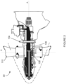
- a feedback ring 104 is supported for rotation with the propeller 30, which rotates about the longitudinal axis A.
- the feedback ring 104 is annular and may be referred to as a beta ring or a beta feedback ring.
- the feedback ring 104 and/or the propeller 30 may be configured as described in one or more of U.S. Patent Application Publication Nos. 2015/0139798 , 2018/0050789 and 2018/0050816 .
- the feedback ring 104 may also supported for longitudinal sliding movement along the longitudinal axis A, e.g. by support members, such as a series of circumferentially spaced beta feedback rods 106 that extend along the longitudinal axis A, where a compression spring 108 surrounds an end portion of each rod 106.
- the propeller 30 may comprise a plurality of angularly arranged blades 110 each of which is rotatable about a radially-extending axis R through a plurality of adjustable blade angles, the blade angle being the angle between the chord line (i.e. a line drawn between the leading and trailing edges of the blade) of the propeller blade section and a plane perpendicular to the axis of propeller rotation.
- the propeller 30 may be a reversing propeller 30 having a plurality of modes of operation, such as feather, full reverse, and forward thrust.
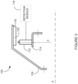
- the system 100 may be used for measurement of rotational speed of propeller systems, such as the engine 10 of Figure 1 .
- the system may be used for detection of position markers 102 of the feedback ring 104.
- the system 100 may be used for control of a crossing threshold used in detecting the position markers 102.
- the system 100 may interface to existing mechanical interfaces of typical propeller systems.
- the system 100 illustratively comprises a plurality of position markers 102 provided on a circumference of the feedback ring 104.
- the feedback ring 104 is used for determining the rotational speed of the propeller 30 and/or to provide blade (or beta) angle position feedback.
- the plurality of position markers 102 rotate with the feedback wheel 104 about the axis of rotation A and their passage is detected by at least one sensor 112 provided in a fixed relationship relative to the rotating propeller components.
- the sensor 112 may be any sensor (e.g. a speed transducer) configured to continuously detect passage of the position markers 102 during rotation of the propeller 30.
- the sensor 112 is an electrically robust and environmentally sealed non-contact sensor suited for harsh environments and offering superior reliability.
- the sensor 112 may be any suitable inductive sensor having a varying reluctance or a Hall effect.
- the sensor 112 is implemented as a transducer comprising a coil wound around a permanent magnet (not shown).
- the position markers 102 may then be made of a magnetically conductive material, e.g. a ferrous metal, to enable the sensor 112 to detect the passage thereof.
- the senor 112 is mounted to a non-rotating part 114 (e.g., a flange) of the engine 10, so as to be positioned adjacent the plurality of position markers 102.
- the sensor 112 is illustratively secured to the propeller 30 so as to extend away from the flange 114 (and towards the position markers 102) along a direction C substantially transverse to the axis of rotation A.
- a single sensor 112 is mounted in close proximity to the feedback ring 104 and the position markers 102.
- two (2) sensors 112 may be mounted in a diametrically opposite relationship relative to the position markers 102, which extend away from the feedback ring 104 and towards the sensor(s) 112. In other embodiments, any suitable number of sensors may be used. In yet another embodiment, several position markers 102 may be spaced equiangularly about the perimeter of the feedback ring 104. Other embodiments may apply.
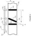
- the position markers 102 comprise a plurality of spaced protrusions or teeth.
- the teeth 102 may be mounted (using any suitable attachment means, such as screws, bolts, and the like) to an inner face 118 of the feedback ring 104 or may be integrally formed with the feedback ring 104.
- a total of three (3) teeth 102 A , 102 B , 102 C is provided about the perimeter of the feedback ring 104, as illustrated. It should however be understood that more or less than three (3) teeth may be provided.
- the configuration of the teeth 102 may vary depending on practical implementations.
- the teeth 102 may be configured as described in one or more of U.S. Patent Application Publication Nos.
- teeth 102 A and 102 C are positioned along a direction D, which is substantially parallel to the axis A and tooth (referred to herein as a detection tooth) 102 B is positioned along a direction E angled to the direction D, such that the tooth 102 B is offset relative to the teeth 102 A and 102 C .
- the configuration of the 102 A , 102 B and 102 C is for illustration purposes only. Accordingly, one or more of the teeth 102 may be angled or none of the teeth 102 may be angled, depending on practical implementations.
- the spacing between consecutive teeth 102 may be equidistant or non-equidistant.
- each sensor 112 may be mounted to the flange 114 adjacent the inner face 118 of the feedback wheel 104, i.e. inside the feedback wheel 104.
- the teeth 102 A , 102 B , 102 C may be mounted to (e.g. extend away from) an outer face 120 (shown in Figure 4 ) of the feedback ring 104 and each sensor 112 may accordingly be positioned adjacent the outer face 120, about a perimeter of the feedback wheel 104.
- the position markers 102 may comprise slots (not shown) rather than teeth, with the slots being formed or otherwise machined in the feedback wheel 104 and made of a magnetically conductive material, e.g. a ferrous metal.
- the feedback ring 104 rotates (e.g. in the direction of arrow F) during rotation of the propeller 30.
- the sensor 112 detects the passage of each one of the position markers 102 A , 102 B , 102 C and accordingly generates an output voltage signal (also referred to herein as a variable mark/space signal).
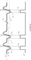
- An example of the output voltage signal is illustrated by waveform 122 in Figure 5A .
- each one of the position markers e.g. position marker 102 A
- the sensor output signal 122 decreases to a negative value and as each one of the position markers (e.g. position marker 102 A ) passes the sensor 112, the sensor output signal 122 (e.g. a single pulse causing a positive voltage transition) increases.
- the sensor output signal 122 e.g. a single pulse causing a positive voltage transition
- the pulse shape is inverted and the sensor output signal 122 is returned to zero. Accordingly, a positive zero-crossing of the sensor output signal 122 may be indicative of the passage of a position marker 102 by the sensor 112.
- FIG. 5B Another example of the sensor output signal 122 is illustrated in Figure 5B .
- the sensor output signal 122 increases to a positive value and as each one of the position markers (e.g. position marker 102 A ) passes the sensor 112, the sensor output signal 122 (e.g. a single pulse causing a negative voltage transition) decreases.
- the sensor output signal 122 e.g. a single pulse causing a negative voltage transition
- the pulse shape is inverted and the sensor output signal 122 is returned to zero. Accordingly, a negative zero-crossing of the sensor output signal 122 may be indicative of the passage of a position marker 102 by the sensor 112.
- the positive zero-crossing (as shown in Figure 5A ) or negative zero-crossing (as shown in Figure 5B ) of the voltage waveform 122 may be used to detect the position markers 102 A , 102 B , 102 C .
- a detection module 116 is electrically connected to the sensor(s) 112 and configured to receive output signal(s) therefrom.
- the sensor's output voltage signal 122 is received at the detection module 116, which continuously monitors the sensor signal 122 to detect the zero-crossing transitions of the voltage waveform 122.
- the detection module 116 may comprise one or more computing devices including, but not limited to, a digital computer, a processor (e.g. a microprocessor), and a memory.
- the detection module 116 may be implemented in a single computing device or may be implemented using various computing devices and/or components.
- the detection module 116 may be implemented using an analog signal processing circuit comprising various passive and/or active electronic components.
- the detection module 116 receives the sensor signal 122 comprising a first series of pulses 135 A , 135 B and 135 C indicative of passage of the position markers 102 by the sensor 112.
- the detection module 116 is configured to detect the zero-crossing transition of each pulse. Rather than only detecting a zero-crossing, the detection module 116 is configured to detect the zero-crossing transition when the sensor signal 122 has a magnitude exceeding a crossing threshold (e.g. after the magnitude of the sensor signal 122 has exceeded the crossing threshold).
- the crossing threshold is a non-zero value and may also be referred to as an arming threshold or an arming level.
- the detection module 116 determines that the increase in voltage corresponds to detection by the sensor 112 of passage of a position marker (e.g. position marker 102 A ).
- the assessment of whether the sensor signal 122 has a magnitude that exceeds the crossing threshold is assessed before the zero-crossing transition is detected.
- the assessment of whether the sensor signal 122 has a magnitude that exceeds the crossing threshold is assessed after the zero-crossing transition is detected.
- another zero-crossing transition is not detected until the crossing threshold is again exceeded. In other words, a subsequent zero-crossing transition is detected when the sensor signal 122 has a zero-crossing having a subsequent magnitude exceeding the crossing threshold.
- the detection module 116 may generate a detection signal 150 comprising a second series of pulses 155 A , 155 B and 155 C , as is illustrated in the example in Figure 6A .
- the second series of pulses 155 A , 155 B and 155 C is indicative of selected pulses from the first series of pulses 135 A , 135 B and 135 C (see Figure 5A ) that have a zero-crossing and have a magnitude that exceeds the crossing threshold 130.
- the assessment of whether the pulses 135 A , 135 B and 135 C have a magnitude that exceeds the crossing threshold 130 is performed prior to the detection of the zero-crossings 140 A , 140 B , 140 C .
- Each pulse 155 A , 155 B and 155 C of the detection signal 150 corresponds to a pulse 135 A , 135 B and 135 C of the sensor signal 122 that has a zero-crossing (positive in Figure 6A and negative in Figure 6B ) 140 A , 140 B , 140 C and a magnitude that exceeds the crossing threshold 130.
- the polarity of the crossing threshold is of the same polarity as the sensor signal 122 as a given position marker (102 A , 102 B or 102 C in Figure 5A ) approaches the sensor 112.
- the detection module 116 identifies a voltage of the sensor signal 122 having a magnitude that exceeds the crossing threshold 130 before the zero-crossing event is detected.
- the detection module 116 may then determine the rotational speed of the propeller 30 from the detection signal 150, based on a time interval elapsed between passage of a plurality of pulses (e.g., the passage of the falling edges) of the second series of pulses 155 A , 155 B and 155c.
- the sensor signal 122 may comprise various different types of noise. Some types of noise present on the sensor signal 122 may be dependent on the rotational speed of the propeller 30, for example, such as noise pulses caused by magnetic hot spots on the feedback ring 104, where the noise pulses increase in magnitude with increasing propeller rotational speed. Some types of noise are not dependent on the rotational speed of the propeller 30, for example, such as electromagnetic interference (EMI) and coil-coil crosstalk during intermittent coil faults. Furthermore, the peak amplitude of the sensor signal 122 may vary with rotational speed of the propeller 30.
- EMI electromagnetic interference
- coil-coil crosstalk during intermittent coil faults
- the peak amplitude of the sensor signal 122 may increase proportionally with the rotational speed of the propeller 30.
- the detection module 116 is configured to adjust the crossing threshold 130 as a function of the rotational speed of the propeller 30. For example, the detection module 116 may compare the rotational speed of the propeller 30 to a speed threshold. Then, when the rotational speed is less than or equal to (i.e., does not exceed) the speed threshold, the detection module 116 may set the crossing threshold 130 at a first value 131. When the rotational speed of the propeller 30 exceeds the speed threshold, the detection module 116 may set the crossing threshold 130 at a second value 132. The first value 131 may correspond to a lower magnitude value than the second value 132.
- the crossing threshold 130 (e.g., the first value 131) is set at a minimum value that is high enough to avoid EMI noise at low propeller rotational speeds but not high enough to miss detection of the position markers 102.
- the crossing threshold 130 may be adjusted.
- the crossing threshold 130 may be adjusted to the second value 132 and/or to an adaptive value, as the peak amplitude of the sensor signal 122 increases with increasing propeller rotational speed. This adjusting of the crossing threshold 130 may further add noise immunity over noise sources not dependent on propeller rotational speed and to keep the crossing threshold 130 higher than the noise sources that are dependent on propeller rotational speed.
- the detection module 116 may compare the rotational speed of the propeller 30 to the speed threshold T RPM . Then, when the rotational speed is less than or equal to (i.e., does not exceed) the speed threshold T RPM , the detection module 116 may operate in a first mode where the crossing threshold 130 is set at a first value 131. When the rotational speed of the propeller 30 exceeds the speed threshold T RPM , the detection module 116 may transition to a second mode of operation where the crossing threshold is set at a value 132.
- the value 132 is illustratively set as a function of the peak amplitude value of the sensor signal 122 and increases with increasing propeller rotational speed, until a maximum possible value (labelled "Max Crossing Threshold” and illustratively set at 1.2V in Figure 6C ) is reached.
- the detection module 116 may set the crossing threshold 130 at a static value (also referred to herein as a "constant value").
- the first value 131 may be a static value (equal to 0.25V in Figure 6C , for illustrative purposed only) that is used while the rotational speed is less than or equal to the speed threshold T RPM .
- the detection module 116 may set the crossing threshold 130 at an adaptive value that changes based on previous peak amplitude values of the sensor signal 122.
- the first value 131 may change based on previous peak amplitude values of the sensor signal 122. That is, the crossing threshold may be set at a ratio (e.g., 1/3) of the peak amplitude value of the sensor signal 122.
- the detection module 116 may set the crossing threshold 130 at an adaptive value that changes based on previous peak amplitude values of the sensor signal 122 (as shown in Figure 6C ).
- the second value 132 may change based on previous peak amplitude values of the sensor signal 122.
- the crossing threshold may be set at a ratio (e.g., 1/3) of the peak amplitude value of the sensor signal 122.
- the ratio used in setting the crossing threshold while the rotational speed is less than or equal to the speed threshold T RPM may be a higher value than the ratio used in setting the crossing threshold while the rotational speed exceeds the speed threshold T RPM .
- the values of the ratio(s) may vary depending on practical implementations.
- the detection module 116 may set the crossing threshold 130 at a static value when the rotational speed exceeds the speed threshold T RPM .
- the second value 132 may be a static value that is used while the rotational speed exceeds the speed threshold T RPM .
- the detection module 116 is configured to adjust the crossing threshold 130 as a function of the peak amplitude of the sensor signal 122. For example, the detection module 116 may compare the peak amplitude of the sensor signal 122 to an amplitude threshold. Then, when the peak amplitude is less than or equal to (i.e., does not exceed) the amplitude threshold, the detection module 116 may set the crossing threshold 130 at the first value 131. When the peak amplitude exceeds the amplitude threshold, the detection module 116 may set the crossing threshold at the second value 132.
- the first and second values 131, 132 may be set as described elsewhere in this document.
- the detection module 116 is configured to adjust the crossing threshold 130 as a function of at least one engine parameter. For example (outside the wording of the claims), the detection module 116 may determine whether at least one engine auxiliary (e.g., ignitor, anti-ice system, engine starter, electrical generator or any other suitable engine auxiliary) is powered on. If the at least one engine auxiliary is powered on, the crossing threshold 130 is set at the first value 131. If the at least one engine auxiliary is powered off, the crossing threshold 130 is set at the second value 132.
- at least one engine auxiliary e.g., ignitor, anti-ice system, engine starter, electrical generator or any other suitable engine auxiliary
- the first value 131 may be set at a higher than the second value 132 (outside the wording of the claims), because an engine auxiliary, when powered on, may provide an additional noise source not present when the engine auxiliary is powered off.
- the detection module 116 may determine whether the engine 10 is set for running on the ground or in-flight idle. If the engine is running on the ground, the crossing threshold 130 is set at the first value 131. If the engine is idling in-flight, the crossing threshold 130 is set at the second value 132.
- the detection module 116 may determine whether a signal (e.g., an engine rotational speed signal, a blade angle position signal or any other suitable signal) is present or lost, while the engine 10 is running. If the signal is lost, the crossing threshold 130 is set at the first value 131. If the signal is present, the crossing threshold 130 is set at the second value 132.
- a signal e.g., an engine rotational speed signal, a blade angle position signal or any other suitable signal
- the crossing threshold 130 is set at the first value 131. If the signal is present, the crossing threshold 130 is set at the second value 132.
- the first value 131 may be set at a higher value than the second value 132 (outside the wording of the claims), because when the noise level in the detection signal 150 is over a certain amount, the crossing threshold 130 may be set to the higher value in an attempt to raise the crossing threshold 130 over any noise present on the sensor signal 122.
- the detection module 116 may set the crossing threshold 130 at the first value 131 when the engine parameter is less than or equal to an engine parameter threshold and set the crossing threshold 130 at the second value 132 when the engine parameter exceeds the engine parameter threshold.
- the engine parameter may be oil pressure, compressor discharge pressure, fuel pressure or any other suitable engine parameter.
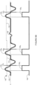
- the sensor signal 122 is illustrated where the crossing threshold 130 has a first value 131 that is then adjusted to a second value 132.
- each of the pulses 135 A , 135 B and 135 C has a positive zero-crossing and has a magnitude that exceeds the crossing threshold 130.
- the detection module 116 detects the passage of the position markers 102 A , 102 B , 102 C .
- the detection module 116 may then generate the example detection signal 150 having pulses 155 A , 155 B and 155 C , which are indicative of the pulses 135 A , 135 B and 135 C of the sensor signal 122 that have a positive zero-crossing and have a magnitude that exceeds the crossing threshold 130.
- the sensor signal 122 has an example noise component 139 with a zero-crossing.
- the noise component 139 does not have a magnitude that exceeds the crossing threshold 130, no zero-crossing transition is detected. Consequently, no pulse corresponding to the noise component 139 is present in the detection signal 150.
- the sensor signal 122 is illustrated where the crossing threshold 130 has a first value 131 that is then adjusted to a second value 132.
- each of the pulses 135 A , 135 B and 135 C has a negative zero-crossing that exceeds the crossing threshold 130.
- the detection module 116 detects the passage of the position markers 102 A , 102 B , 102 C .
- the detection module 116 may then generate the example detection signal 150 having pulses 155 A , 155 B and 155 C , which are indicative of the pulses 135 A , 135 B and 135 C of the sensor signal 122 that have a negative zero-crossing and have a magnitude that exceeds the crossing threshold 130.
- the sensor signal 122 and the detection signal 150 are illustrated as being synchronous in time in Figures 6A and 6B , this is for illustration purposes only to illustrate corresponding pulses between the two signals 122, 150. It should be appreciated that there would typically be a time delay between the sensor signal 122 and the detection signal 150, the delay typically depending on the processing time of the detection module 116.
- the detection module 116 may further determine, from the output signal(s) received the sensor(s) 112, the rotational speed of the propeller 30. Other applications will be readily understood by a person skilled in the art.
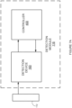
- the detection module 116 comprises a detection device 160 and a controller 400.
- the detection device 160 is electrically connected to the sensor(s) 112.
- the detection device 160 may be an interface device for use with a variable reluctance or magnetic core sensor(s).
- the detection device 160 may be implemented using a MAX9924-MAX9927 variable reluctance sensor interface device provided by Maxim Integrated Products Inc.
- the detection device 160 processes the sensor signal 122 to generate the detection signal 150.
- the controller 400 is electrically connected to the detection device 160 for obtaining the detection signal 150 from the detection device 160 and for controlling the detection device 160.
- the controller 400 may be any suitable computing device.
- the controller 400 may determine the rotational speed of the propeller 30 from the detection signal and/or may cause the detection device 160 to adjust the crossing threshold 130 that the detection device 160 uses in determining the detection signal 150.
- the crossing threshold 130 that the detection device 160 uses may be set in different manners depending on a mode of operation of the detection device 160.
- the detection device 160 may operate in at least two modes of operation.
- a reference voltage applied at an external (EXT) input of the detection device 160 is used to set the crossing threshold 130.
- the controller 400 may apply a voltage level at the EXT input to set the crossing threshold 130 at a given value. This may be done by the controller 400 providing a pulse width modulation (PWM) signal that is filtered and applied to the EXT input of the detection device 160.
- PWM pulse width modulation
- the controller 400 may apply a voltage level with a constant value at the EXT input to set the crossing threshold 130 at a constant value.
- the controller 400 may adjust the voltage level at the EXT input to adjust the crossing threshold 130 (e.g., to implement a crossing threshold 130 with an adaptive value).
- an adaptive threshold feature is enabled in the detection device 160.
- the detection device 160 may adaptively adjust the crossing threshold 130 based on previous peak amplitude values of the sensor signal 122.
- the controller 400 may command the detection device 160 to set the crossing threshold at a ratio (e.g., 1/3) of the peak amplitude value of the sensor signal 122.
- the value of the ratio used by the detection device 160 may be set by the controller 400 or may be a value automatically set by the detection device 160. Accordingly, as the sensor signal's peak voltage rises, the crossing threshold 130 is also increased by the same ratio. Conversely, decreasing peak voltage levels of the sensor signal 122 causes the crossing threshold 130 to decrease to a lower level.
- the controller 400 may control the mode of operation of the detection device 160 (and accordingly the crossing threshold 130) based on the rotational speed of the propeller 30.
- the controller 400 is configured to provide control signals to the detection device 160 to control the mode of operation of the detection device 160.
- the controller 400 may compare the rotational speed of the propeller 30 to the speed threshold. When the rotational speed is less than or equal to the speed threshold, the controller 400 may command the detection device 160 to operate in the first mode and may command the detection device 160 to set the crossing threshold 130 at a given value.
- the given value may be a static value or the controller 400 may command the detection device to adjust the given value (e.g., by varying the voltage applied at the EXT input to adaptively adjust the crossing threshold 130).
- the controller 400 may command the detection device 160 to operate in the second mode (i.e. where the detection device 160 automatically and adaptively adjusts the crossing threshold 130).
- the controller 400 may control the mode of operation of the detection device 160 (and accordingly the crossing threshold 130) based on the engine parameter.
- the controller 400 may command the detection device 160 to operate in the first mode or the second mode depending on the engine parameter. For example, the if the engine parameter has the first condition the controller 400 may command the detection device 160 to operate in the first mode; and if the engine parameter has the second condition, the controller 400 may command the detection device 160 to operate in the second mode.
- the controller 400 may command the detection device 160 to operate in the first mode; and if the engine parameter exceeds the engine parameter threshold, the controller 400 may command the detection device 160 to operate in the second mode.
- a digital counter (not illustrated in Figure 7A ), may be provided in the detection module 116.
- the digital counter may be implemented in the controller 400 or may be a separate physical device (e.g., a free-running 20 MHz counter) that receives the detection signal 150 from the detection device 160 and provides a count signal to the controller 400.
- the digital counter may determine the time interval elapsed between passage of each pulse 155 A , 155 B and 155 C of the detection signal 150 and hence determine the time interval elapsed between passage of the position markers 120 nearby (e.g. adjacent) the sensor 112.
- the digital counter starts counting the number of digital clock cycles between detection of a first position marker (e.g., position marker 102 A ) and detection of the next position marker (e.g. position marker 102 A ).
- the digital counter may start counting the number of digital clock cycles between positive transitions of the detection signal 150.
- the digital count may record time-stamps of the passage of each pulse 155 A , 155 B and 155 C of the detection signal 150.
- the rotational speed of the propeller 30 is determined from the detection signal 150.
- the rotational speed is determined based on a time interval between a plurality of pulses of the second series of pulses 155 A , 155 B and 155 C .
- each detection of the tooth indicates one (1) revolution of the feedback ring 104 (and the shaft 24).
- the time interval elapsed between passage of two consecutive pulses of the detection signal 150 conveys the time required for one revolution and the rotational speed corresponds to the inverse of this time interval.
- the rotational speed may be determined based on a time interval between a plurality of pulses of the detection signal 150, based on the number of position markers 102 on the feedback ring 104, and based on the number of pulses detected in the time interval. For example, a number of pulses of the detection signal 150 may be monitored over a time period (e.g., multiple time intervals detected by the counter). Then, the rotational speed may be determined from the time period (e.g., the summation of these multiple time intervals), the number of pulses detected over this time period, and the number of position markers 102 on the feedback ring 104.
- the rotational speed is determined as a function of time-stamps of a given number of detected zero-crossing events from the detection signal 150.
- a buffer may store time-stamp values corresponding to the detected zero-crossing events. The elapsed time between the given number of detected zero-crossing events may then be determined. When the given number corresponds to the number of position markers 102 on the feedback ring 104, the value of the determined elapsed time may be inverted and multiplied by sixty (60) to determine the propeller speed in RPMs.
- the feedback ring 104 comprises seventeen (17) position markers 102
- the total elapsed time between seventeen (17) zero-crossing events is determined; then, the determined elapsed time is inverted and multiplied by sixty (60) to determine the propeller speed in RPMs.
- a rolling buffer of a certain number of values e.g., 17 values
- each detected zero-crossing event timestamp is inserted at the first value of the buffer and the last value of the buffer (e.g., the 17 th value) corresponding to the oldest value is discarded.
- the counter determines the number of clock cycles between detection of passage of the teeth 102 A , 102 C and detection of passage of a detection tooth 102 B of the feedback ring 104, as indicated in the detection signal 150.
- the interval of time between the passage of a first tooth 102 A and the passage of the detection tooth 102 B is indicated as Tm while the interval of time between the passage of the detection tooth 102 B and the passage of a second tooth 102 C is indicated as Ts.
- the detected time intervals Tm and Ts are then stored in the memory for subsequent processing by the detection module 116.
- the rotational speed can be computed on the basis of the sum of the timeframe values (Tm + Ts) and the number of position markers 102A, 102B, 102C, using known computation methods.
- the detection module 116 comprises the controller 400 and an analog-to-digital (A/D) converter 162 is provided to digitize the analog waveform from the sensor 112.
- the analog-to-digital converter 162 may be provided separate from the controller 400 or the sensor 112. Alternatively, the analog-to-digital converter 162 may be provided as part of the controller 400 or the sensor 112. The analog-to-digital converter 162 may be provided as part of the detection module 116. In other embodiments, the sensor 112 may provide a digital signal and the analog-to-digital converter 162 may be omitted.
- the controller 400 is configured to implement the functionality of the detection device 160 as described elsewhere in this document.
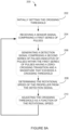
- the crossing threshold 130 is initially set (i.e., the crossing threshold is set at an initial value). For instance, at start-up of the engine 10 or the start of performance of method 200, the crossing threshold 130 may be initially set at the first value 131.
- a mode of operation (e.g., the first mode) may be set and the crossing threshold 130 may be set based on this mode of operation.
- the sensor signal 122 is received.
- the sensor signal 122 comprises the first series of pulses 135 A , 135 B and 135 C indicative of passage of position markers 102 A , 102 B and 102 C about a circumference of the propeller shaft 24.
- the detection signal 150 is generated.
- the detection signal 150 comprises the second series of 155 A , 155 B and 155 C indicative of pulses within the first series of pulses 135 A , 135 B and 135 C that have a zero-crossing transition 140 A , 140 B and 140 C and a magnitude that exceeds the crossing threshold 130.
- the rotational speed of the propeller 30 is determined from the detection signal 150 based on a time interval between a plurality of pulses the second series of pulses 155 A , 155 B and 155 C .
- the crossing threshold is adjusted as a function of the rotational speed. After step 210, the method 200 may return to step 204 and repeat steps 204 to 210 during operation of the engine 10.
- the blade angle (or beta position) of the propeller 30 may be determined from a second series of pulses 155 A , 155 B and 155 C .
- the blade angle may be determined from the second series of pulses 155 A , 155 B and 155 C using the techniques described in U.S. Patent Application Publication Nos. 2015/0139798 , 2018/0050789 and 2018/0050816 .
- the determined rotational speed (and/or blade angle) may be outputted to an aircraft computer, for example, to display the rotational speed (and/or the blade angle) on an aircraft or cockpit display.
- the determined rotational speed (and/or blade angle) may be used by the controller 400 (or another engine controller and/or aircraft computer) for various engine and/or aircraft control.
- the determined rotational speed (and/or blade angle) may be used to adjust the fuel flow to the engine.
- the determined rotational speed may be used as feedback for propeller speed governing.
- the determined blade angle may be used as feedback for setting for propeller servo piston oil flow to set the propeller blade angle.
- step 210 for adjusting the crossing threshold 130 is illustrated.
- the rotational speed is compared to a speed threshold.
- the speed threshold may be a predetermined value that is determined based on noise characteristics of the sensor signal 122 as a function of rotational speed of the propeller 30. For example, it may be known that for propeller rotational speeds between 0 and 500 RPM, the sensor signal 122 may exhibit a high level of noise. Thus, when the propeller rotational speed is less than or equal to 500 RPM, the crossing threshold 130 may be set at a higher value than when the propeller rotational speed exceeds 500 RPM (outside the wording of the claims).
- the crossing threshold 130 is set at the first value 131 (or maintained at the first value 131, if the crossing threshold 130 is currently set at the first value).
- setting the crossing threshold 130 at the first value 131 may comprises setting the crossing threshold 130 at a constant value or may comprise setting the crossing threshold 139 at a value that is a function of a peak amplitude of a previous one of the sensor signal 122.
- the crossing threshold 130 is set at the second value 132.
- setting the crossing threshold 130 at the second value 132 may comprises setting the crossing threshold 130 at a value that is a function of a peak amplitude the sensor signal 122.
- setting and/or adjusting the crossing threshold 130 at step 202 and/or step 210 comprises the controller 400 commanding the detection device 160 to set the crossing threshold 130.
- the controller 400 commanding the detection device 160 to set the crossing threshold 130 comprises providing a value for setting the crossing threshold 130.
- the controller 400 commanding the detection device 160 to set the crossing threshold 130 comprise determining a mode of operation for the detection device 160 and commanding the detection device 160 to operate in the determined mode of operation. For example, the detection device 160 may be commanded to operate in the first mode and be commanded to set the crossing threshold 130 at a given value (e.g., a constant value or a value that is a function of a peak amplitude of the sensor signal 122).
- This commanding of the detection device 160 to operate in the first mode may be done when the rotational speed is less than or equal to the speed threshold or when initially performing the method 200.
- the detection device 160 may be commanded to operate in the second mode, where the crossing threshold 130 is set at an adaptive value that varies depending on a peak amplitude of the sensor signal 122. This commanding of the detection device 160 in the second mode may be done when the rotational speed exceeds the speed threshold.
- the detection device 160 is configured to receive the sensor signal 122 from the sensor 112 at step 204 and to generate the detection signal 150 at step 206.
- the controller 400 receives the detection signal 150 from the detection device 160. Accordingly, steps 202, 208 and 210 may be performed by the controller 400.
- the detection device 160 may be commanded to operate in the first mode of operation without necessarily having to operate in the second mode.
- the controller 400 may adjust the crossing threshold 130 by applying a voltage signal to the EXT input of the detection device 160.
- the adjusting of the crossing threshold 130 may be done by the controller 400 outputting a PWM signal that is then filtered and applied to the EXT input.
- the controller 400 may be configured to function in a similar manner to the functionality of the detection device 160, when the detection device 160 is operating in the second mode of operation. For example, the controller 400 may adjust the PWM signal to set the crossing threshold at an adaptive value that varies depending on a peak amplitude of a previous pulse of the first series of pulses of the sensor signal 122.
- the engine parameter is monitored.
- the engine parameter monitored is indicative of the rotational speed of the propeller 30.
- the engine parameter varies with rotational speed.
- One or more sensors may be used to obtain the engine parameter or the engine parameter may be provided by an engine or aircraft computer.
- the crossing threshold 130 is determined as a function of the engine parameter.
- the sensor signal 122 is received.
- the sensor signal 122 comprises the first series of pulses 135 A , 135 B and 135 C indicative of passage of position markers 102 A , 102 B and 102 C about a circumference of the propeller shaft 24.
- the detection signal 150 is generated.
- the detection signal 150 comprises the second series of 155 A , 155 B and 155 C indicative of pulses within the first series of pulses 135 A , 135 B and 135 C that have a zero-crossing transition 140 A , 140 B and 140 C and a magnitude that exceeds the crossing threshold 130.
- the rotational speed of the propeller 30 is determined from the detection signal 150 based on a time interval between a plurality of pulses the second series of pulses 155 A , 155 B and 155 C .
- the method 200' may then be repeated during operation of the engine 10.
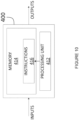
- the methods 200, 200' may be implemented at least in part using the computing device 400 comprising a processing unit 412 and a memory 414 which has stored therein computer-executable instructions 416.
- the processing unit 412 may comprise any suitable devices configured such that instructions 416, when executed by the computing device 400 or other programmable apparatus, may cause the functions/acts/steps of the methods 200, 200' as described herein to be executed.
- the processing unit 412 may comprise, for example, any type of general-purpose microprocessor or microcontroller, a digital signal processing (DSP) processor, a central processing unit (CPU), an integrated circuit, a field programmable gate array (FPGA), a reconfigurable processor, other suitably programmed or programmable logic circuits, or any combination thereof.
- DSP digital signal processing
- CPU central processing unit
- FPGA field programmable gate array
- reconfigurable processor other suitably programmed or programmable logic circuits, or any combination thereof.
- the memory 414 may comprise any suitable known or other machine-readable storage medium.
- the memory 414 may comprise non-transitory computer readable storage medium, for example, but not limited to, an electronic, magnetic, optical, electromagnetic, infrared, or semiconductor system, apparatus, or device, or any suitable combination of the foregoing.
- the memory 414 may include a suitable combination of any type of computer memory that is located either internally or externally to device, for example random-access memory (RAM), read-only memory (ROM), compact disc read-only memory (CDROM), electro-optical memory, magnetooptical memory, erasable programmable read-only memory (EPROM), and electrically-erasable programmable read-only memory (EEPROM), Ferroelectric RAM (FRAM) or the like.
- Memory 414 may comprise any storage means (e.g., devices) suitable for retrievably storing machine-readable instructions 416 executable by processing unit 412.
- the computing device 400 can be implemented as part of a full-authority digital engine controls (FADEC) or other similar device, including electronic engine control (EEC), engine control unit (ECU), and the like.
- FADEC full-authority digital engine controls
- EEC electronic engine control
- ECU engine control unit
- the methods and systems for controlling the crossing threshold described herein may be implemented in a high level procedural or object oriented programming or scripting language, or a combination thereof, to communicate with or assist in the operation of a computer system, for example the computing device 400.
- the methods and systems for controlling the crossing threshold may be implemented in assembly or machine language.
- the language may be a compiled or interpreted language.
- Program code for implementing the methods and systems for controlling the crossing threshold may be stored on a storage media or a device, for example a ROM, a magnetic disk, an optical disc, a flash drive, or any other suitable storage media or device.
- the program code may be readable by a general or special-purpose programmable computer for configuring and operating the computer when the storage media or device is read by the computer to perform the procedures described herein.
- Embodiments of the methods and systems for controlling the crossing threshold may also be considered to be implemented by way of a non-transitory computer-readable storage medium having a computer program stored thereon.
- the computer program may comprise computer-readable instructions which cause a computer, or in some embodiments the processing unit 412 of the computing device 400, to operate in a specific and predefined manner to perform the functions described herein.
- Computer-executable instructions may be in many forms, including program modules, executed by one or more computers or other devices.
- program modules include routines, programs, objects, components, data structures, etc., that perform particular tasks or implement particular abstract data types.
- functionality of the program modules may be combined or distributed as desired in various embodiments.
- the detection device 160 may be implemented in a similar manner to the computing device 400, and may comprise a processing unit (similar to the processing unit 412) and a memory (similar to the memory 414) which has stored therein computer-executable instructions (similar to the computer-executable instructions 416).
Landscapes
- Engineering & Computer Science (AREA)
- Chemical & Material Sciences (AREA)
- Combustion & Propulsion (AREA)
- Aviation & Aerospace Engineering (AREA)
- Mechanical Engineering (AREA)
- General Engineering & Computer Science (AREA)
- Physics & Mathematics (AREA)
- General Physics & Mathematics (AREA)
- Transmission And Conversion Of Sensor Element Output (AREA)
- Combined Controls Of Internal Combustion Engines (AREA)
Description
- The present disclosure relates generally to propeller feedback systems, and, more particularly, to methods and systems for controlling a crossing threshold of a propeller of an aircraft engine.
- Some aircraft engines have propellers with a feedback ring mounted for rotation with the propeller. In such engines, the rotational speed of the propeller can be obtained from measuring the rotational speed of the feedback ring using local changes in a magnetic field.
- However, existing systems for determining the rotational speed of the propeller may inaccurately determine the rotational speed of the propeller under certain circumstances.
- As such, there is a need for improvement.
-
US 2013/0328554 A1 discloses a variable reluctance sensor (VRS) with an 1/t arming function,US 4169232 - A discloses a signal conditioning circuit for magnetic sensing means,
US 2005/0122098 A1 discloses a method and assembly for determining rational speed with variable switching hysteresis, andUS 3801830 A discloses a signal amplification circuit with phase detecting means and variable signal level recognition means. - In one aspect, there is provided a method as set forth in
claim 1. - In another aspect, there is provided a system as set forth in claim 2.
- Embodiments of the disclosure are set forth in the dependent claims.
- Reference is now made to the accompanying figures in which:
-
Figure 1 is a schematic cross-sectional view of a gas turbine engine; -
Figure 2 is a schematic diagram of a propeller assembly comprising a feedback ring, in accordance with an illustrative embodiment; -
Figure 3 is a schematic diagram of a system for detection of position markers of the feedback ring ofFigure 2 , in accordance with an illustrative embodiment; -
Figure 4 illustrates an arrangement ofFigure 3 taken along view A rotated by ninety degrees, in accordance with an illustrative embodiment; -
Figure 5A is a schematic diagram illustrating operation of a sensor with a sensor signal having a negative polarity as position markers approach the sensor, in accordance with an illustrative embodiment; -
Figure 5B is a schematic diagram illustrating operation of a sensor with a sensor signal having a positive polarity as position markers approach the sensor, in accordance with an illustrative embodiment; -
Figure 6A illustrates the sensor signal ofFigure 5A and a crossing threshold used in detecting positive zero-crossing transitions of pulses of the sensor signal that exceed the crossing threshold; -
Figure 6B illustrates the sensor signal ofFigure 5B and a crossing threshold used in detecting negative zero-crossing transitions of pulses of the sensor signal that exceed the crossing threshold; -
Figure 6C is a plot of an example crossing threshold as a function of propeller rotational speed, in accordance with an illustrative embodiment; -
Figure 7A is a block diagram of the detection module ofFigure 3 , in accordance with an illustrative embodiment; -
Figure 7B is a block diagram of a variant of the detection module ofFigure 3 , in accordance with an illustrative embodiment; -
Figure 8A is a flowchart of a method for controlling a crossing threshold, in accordance with an embodiment; -
Figure 8B is a flowchart illustrating the step ofFigure 8 of adjusting the crossing threshold as a function of propeller rotational speed, in accordance with an embodiment; -
Figure 9 is a flowchart of a method for determining propeller rotational speed, in accordance with an embodiment; and -
Figure 10 is a block diagram of an example computing system for implementing the method ofFigure 8A and9 in accordance with an embodiment. - It will be noted that throughout the appended drawings, like features are identified by like reference numerals.
-
Figure 1 illustrates agas turbine engine 10, of a type typically provided for use in subsonic flight, comprising aninlet 12, through which ambient air is propelled, acompressor section 14 for pressurizing the air, acombustor 16 in which the compressed air is mixed with fuel and ignited for generating an annular stream of hot combustion gases, and aturbine section 18 for extracting energy from the combustion gases. Theturbine section 18 illustratively comprises acompressor turbine 20, which drives the compressor assembly and accessories, and at least one power orfree turbine 22, which is independent from thecompressor turbine 20 and rotatingly drives arotor shaft 24 about a longitudinal propeller shaft axis A through areduction gear box 26. Hot gases may then be evacuated throughexhaust stubs 28. The gas generator of theengine 10 illustratively comprises thecompressor section 14, thecombustor 16, and theturbine section 18. Arotor 30, in the form of a propeller through which ambient air is propelled, is hosted in apropeller hub 32.Rotor 30 may, for example, comprise a propeller of a fixed-wing aircraft or a main (or tail) rotor of a rotary-wing aircraft such as a helicopter. Therotor 30 may comprise a plurality of circumferentially-arranged blades connected to a hub by any suitable means and extending radially therefrom. The blades are also each rotatable about their own radial axes through a plurality of blade angles, which can be changed to achieve modes of operation, such as feather, full reverse, and forward thrust. - As depicted in
Figure 2 , afeedback ring 104 is supported for rotation with thepropeller 30, which rotates about the longitudinal axis A. Thefeedback ring 104 is annular and may be referred to as a beta ring or a beta feedback ring. - The
feedback ring 104 and/or thepropeller 30 may be configured as described in one or more ofU.S. Patent Application Publication Nos. 2015/0139798 ,2018/0050789 and2018/0050816 . For example, thefeedback ring 104 may also supported for longitudinal sliding movement along the longitudinal axis A, e.g. by support members, such as a series of circumferentially spacedbeta feedback rods 106 that extend along the longitudinal axis A, where acompression spring 108 surrounds an end portion of eachrod 106. Thepropeller 30 may comprise a plurality of angularly arrangedblades 110 each of which is rotatable about a radially-extending axis R through a plurality of adjustable blade angles, the blade angle being the angle between the chord line (i.e. a line drawn between the leading and trailing edges of the blade) of the propeller blade section and a plane perpendicular to the axis of propeller rotation. Thepropeller 30 may be a reversingpropeller 30 having a plurality of modes of operation, such as feather, full reverse, and forward thrust. - With additional reference to
Figure 3 , asystem 100 will now be described. In accordance with an embodiment, thesystem 100 may be used for measurement of rotational speed of propeller systems, such as theengine 10 ofFigure 1 . The system may be used for detection ofposition markers 102 of thefeedback ring 104. Thesystem 100 may be used for control of a crossing threshold used in detecting theposition markers 102. Thesystem 100 may interface to existing mechanical interfaces of typical propeller systems. - The
system 100 illustratively comprises a plurality ofposition markers 102 provided on a circumference of thefeedback ring 104. Thefeedback ring 104 is used for determining the rotational speed of thepropeller 30 and/or to provide blade (or beta) angle position feedback. During rotation of thepropeller 30, the plurality ofposition markers 102 rotate with thefeedback wheel 104 about the axis of rotation A and their passage is detected by at least onesensor 112 provided in a fixed relationship relative to the rotating propeller components. Thesensor 112 may be any sensor (e.g. a speed transducer) configured to continuously detect passage of theposition markers 102 during rotation of thepropeller 30. In one embodiment, thesensor 112 is an electrically robust and environmentally sealed non-contact sensor suited for harsh environments and offering superior reliability. Thesensor 112 may be any suitable inductive sensor having a varying reluctance or a Hall effect. In one embodiment, thesensor 112 is implemented as a transducer comprising a coil wound around a permanent magnet (not shown). Theposition markers 102 may then be made of a magnetically conductive material, e.g. a ferrous metal, to enable thesensor 112 to detect the passage thereof. - In the illustrated embodiment, the
sensor 112 is mounted to a non-rotating part 114 (e.g., a flange) of theengine 10, so as to be positioned adjacent the plurality ofposition markers 102. In particular, thesensor 112 is illustratively secured to thepropeller 30 so as to extend away from the flange 114 (and towards the position markers 102) along a direction C substantially transverse to the axis of rotation A. In one embodiment, asingle sensor 112 is mounted in close proximity to thefeedback ring 104 and theposition markers 102. In another embodiment, in order to provide loss of probe protection, two (2)sensors 112 may be mounted in a diametrically opposite relationship relative to theposition markers 102, which extend away from thefeedback ring 104 and towards the sensor(s) 112. In other embodiments, any suitable number of sensors may be used. In yet another embodiment,several position markers 102 may be spaced equiangularly about the perimeter of thefeedback ring 104. Other embodiments may apply. - As shown in
Figure 4 , in one embodiment, theposition markers 102 comprise a plurality of spaced protrusions or teeth. Theteeth 102 may be mounted (using any suitable attachment means, such as screws, bolts, and the like) to aninner face 118 of thefeedback ring 104 or may be integrally formed with thefeedback ring 104. In one embodiment, a total of three (3)teeth feedback ring 104, as illustrated. It should however be understood that more or less than three (3) teeth may be provided. The configuration of theteeth 102 may vary depending on practical implementations. Theteeth 102 may be configured as described in one or more ofU.S. Patent Application Publication Nos. 2015/0139798 ,2018/0050789 and2018/0050816 . In the illustrated embodiment,teeth tooth 102B is offset relative to theteeth teeth 102 may be angled or none of theteeth 102 may be angled, depending on practical implementations. The spacing betweenconsecutive teeth 102 may be equidistant or non-equidistant. As illustrated inFigure 3 , eachsensor 112 may be mounted to theflange 114 adjacent theinner face 118 of thefeedback wheel 104, i.e. inside thefeedback wheel 104. In an alternate embodiment, theteeth Figure 4 ) of thefeedback ring 104 and eachsensor 112 may accordingly be positioned adjacent theouter face 120, about a perimeter of thefeedback wheel 104. In yet another embodiment, theposition markers 102 may comprise slots (not shown) rather than teeth, with the slots being formed or otherwise machined in thefeedback wheel 104 and made of a magnetically conductive material, e.g. a ferrous metal. - In operation, the
feedback ring 104 rotates (e.g. in the direction of arrow F) during rotation of thepropeller 30. Thesensor 112 then detects the passage of each one of theposition markers waveform 122 inFigure 5A . In particular, as theposition markers propeller 30, each one of the position markers (e.g. position marker 102A) approaches thesensor 112. This changes the sensor's reluctance and causes a magnetic field to be generated and current to flow in the sensor's coil. In the example ofFigure 5A , as each one of the position markers (e.g. position marker 102A) approaches thesensor 112, thesensor output signal 122 decreases to a negative value and as each one of the position markers (e.g. position marker 102A) passes thesensor 112, the sensor output signal 122 (e.g. a single pulse causing a positive voltage transition) increases. When the given position marker (e.g. position marker 102A) moves away from thesensor 112, the pulse shape is inverted and thesensor output signal 122 is returned to zero. Accordingly, a positive zero-crossing of thesensor output signal 122 may be indicative of the passage of aposition marker 102 by thesensor 112. - Another example of the
sensor output signal 122 is illustrated inFigure 5B . In the example ofFigure 5B , as each one of the position markers (e.g. position marker 102A) approaches thesensor 112, thesensor output signal 122 increases to a positive value and as each one of the position markers (e.g. position marker 102A) passes thesensor 112, the sensor output signal 122 (e.g. a single pulse causing a negative voltage transition) decreases. When the given position marker (e.g. position marker 102A) moves away from thesensor 112, the pulse shape is inverted and thesensor output signal 122 is returned to zero. Accordingly, a negative zero-crossing of thesensor output signal 122 may be indicative of the passage of aposition marker 102 by thesensor 112. - Thus, depending on the configuration of the
sensor 112 and on the polarity of thesensor signal 122 as it approaches thesensor 112, the positive zero-crossing (as shown inFigure 5A ) or negative zero-crossing (as shown inFigure 5B ) of thevoltage waveform 122 may be used to detect theposition markers - Referring back to
Figure 3 , adetection module 116 is electrically connected to the sensor(s) 112 and configured to receive output signal(s) therefrom. The sensor'soutput voltage signal 122 is received at thedetection module 116, which continuously monitors thesensor signal 122 to detect the zero-crossing transitions of thevoltage waveform 122. Thedetection module 116 may comprise one or more computing devices including, but not limited to, a digital computer, a processor (e.g. a microprocessor), and a memory. Thedetection module 116 may be implemented in a single computing device or may be implemented using various computing devices and/or components. Thedetection module 116 may be implemented using an analog signal processing circuit comprising various passive and/or active electronic components. Thedetection module 116 receives thesensor signal 122 comprising a first series of pulses 135A, 135B and 135C indicative of passage of theposition markers 102 by thesensor 112. Thedetection module 116 is configured to detect the zero-crossing transition of each pulse. Rather than only detecting a zero-crossing, thedetection module 116 is configured to detect the zero-crossing transition when thesensor signal 122 has a magnitude exceeding a crossing threshold (e.g. after the magnitude of thesensor signal 122 has exceeded the crossing threshold). The crossing threshold is a non-zero value and may also be referred to as an arming threshold or an arming level. Accordingly, when such a zero-crossing transition is detected and thesensor signal 122 has a magnitude that exceeds the crossing threshold, thedetection module 116 determines that the increase in voltage corresponds to detection by thesensor 112 of passage of a position marker (e.g. position marker 102A). In some embodiments, the assessment of whether thesensor signal 122 has a magnitude that exceeds the crossing threshold is assessed before the zero-crossing transition is detected. In other embodiments, the assessment of whether thesensor signal 122 has a magnitude that exceeds the crossing threshold is assessed after the zero-crossing transition is detected. Upon detecting a zero-crossing transition having a magnitude exceeding the crossing threshold, another zero-crossing transition is not detected until the crossing threshold is again exceeded. In other words, a subsequent zero-crossing transition is detected when thesensor signal 122 has a zero-crossing having a subsequent magnitude exceeding the crossing threshold. - The
detection module 116 may generate adetection signal 150 comprising a second series of pulses 155A, 155B and 155C, as is illustrated in the example inFigure 6A . The second series of pulses 155A, 155B and 155C is indicative of selected pulses from the first series of pulses 135A, 135B and 135C (seeFigure 5A ) that have a zero-crossing and have a magnitude that exceeds thecrossing threshold 130. In this example, the assessment of whether the pulses 135A, 135B and 135C have a magnitude that exceeds thecrossing threshold 130 is performed prior to the detection of the zero-crossings 140A, 140B, 140C. Each pulse 155A, 155B and 155C of thedetection signal 150 corresponds to a pulse 135A, 135B and 135C of thesensor signal 122 that has a zero-crossing (positive inFigure 6A and negative inFigure 6B ) 140A, 140B, 140C and a magnitude that exceeds thecrossing threshold 130. In accordance with an embodiment, the polarity of the crossing threshold is of the same polarity as thesensor signal 122 as a given position marker (102A, 102B or 102C inFigure 5A ) approaches thesensor 112. In the examples illustrated inFigures 6A and6B , thedetection module 116 identifies a voltage of thesensor signal 122 having a magnitude that exceeds thecrossing threshold 130 before the zero-crossing event is detected. Thedetection module 116 may then determine the rotational speed of thepropeller 30 from thedetection signal 150, based on a time interval elapsed between passage of a plurality of pulses (e.g., the passage of the falling edges) of the second series ofpulses 155A, 155B and 155c. - It should be appreciated that, by using the
crossing threshold 130, false detection of passage of theposition markers 102 may be reduced. Thesensor signal 122 may comprise various different types of noise. Some types of noise present on thesensor signal 122 may be dependent on the rotational speed of thepropeller 30, for example, such as noise pulses caused by magnetic hot spots on thefeedback ring 104, where the noise pulses increase in magnitude with increasing propeller rotational speed. Some types of noise are not dependent on the rotational speed of thepropeller 30, for example, such as electromagnetic interference (EMI) and coil-coil crosstalk during intermittent coil faults. Furthermore, the peak amplitude of thesensor signal 122 may vary with rotational speed of thepropeller 30. For example, the peak amplitude of thesensor signal 122 may increase proportionally with the rotational speed of thepropeller 30. In accordance with an embodiment, thedetection module 116 is configured to adjust thecrossing threshold 130 as a function of the rotational speed of thepropeller 30. For example, thedetection module 116 may compare the rotational speed of thepropeller 30 to a speed threshold. Then, when the rotational speed is less than or equal to (i.e., does not exceed) the speed threshold, thedetection module 116 may set thecrossing threshold 130 at afirst value 131. When the rotational speed of thepropeller 30 exceeds the speed threshold, thedetection module 116 may set thecrossing threshold 130 at asecond value 132. Thefirst value 131 may correspond to a lower magnitude value than thesecond value 132. It should be appreciated that it is desirable that the crossing threshold 130 (e.g., the first value 131) is set at a minimum value that is high enough to avoid EMI noise at low propeller rotational speeds but not high enough to miss detection of theposition markers 102. Once the propeller rotational speed is high enough (e.g., over the speed threshold), thecrossing threshold 130 may be adjusted. Thecrossing threshold 130 may be adjusted to thesecond value 132 and/or to an adaptive value, as the peak amplitude of thesensor signal 122 increases with increasing propeller rotational speed. This adjusting of thecrossing threshold 130 may further add noise immunity over noise sources not dependent on propeller rotational speed and to keep thecrossing threshold 130 higher than the noise sources that are dependent on propeller rotational speed. - With reference to
Figure 6C , thedetection module 116 may compare the rotational speed of thepropeller 30 to the speed threshold TRPM. Then, when the rotational speed is less than or equal to (i.e., does not exceed) the speed threshold TRPM, thedetection module 116 may operate in a first mode where thecrossing threshold 130 is set at afirst value 131. When the rotational speed of thepropeller 30 exceeds the speed threshold TRPM, thedetection module 116 may transition to a second mode of operation where the crossing threshold is set at avalue 132. Thevalue 132 is illustratively set as a function of the peak amplitude value of thesensor signal 122 and increases with increasing propeller rotational speed, until a maximum possible value (labelled "Max Crossing Threshold" and illustratively set at 1.2V inFigure 6C ) is reached. - When the rotational speed is less than or equal to the speed threshold TRPM, the
detection module 116 may set thecrossing threshold 130 at a static value (also referred to herein as a "constant value"). In other words, thefirst value 131 may be a static value (equal to 0.25V inFigure 6C , for illustrative purposed only) that is used while the rotational speed is less than or equal to the speed threshold TRPM. In some embodiments, when the rotational speed is less than or equal to the speed threshold TRPM, thedetection module 116 may set thecrossing threshold 130 at an adaptive value that changes based on previous peak amplitude values of thesensor signal 122. In other words, thefirst value 131 may change based on previous peak amplitude values of thesensor signal 122. That is, the crossing threshold may be set at a ratio (e.g., 1/3) of the peak amplitude value of thesensor signal 122. - When the rotational speed exceeds the speed threshold TRPM, the
detection module 116 may set thecrossing threshold 130 at an adaptive value that changes based on previous peak amplitude values of the sensor signal 122 (as shown inFigure 6C ). In other words, thesecond value 132 may change based on previous peak amplitude values of thesensor signal 122. That is, the crossing threshold may be set at a ratio (e.g., 1/3) of the peak amplitude value of thesensor signal 122. The ratio used in setting the crossing threshold while the rotational speed is less than or equal to the speed threshold TRPM may be a higher value than the ratio used in setting the crossing threshold while the rotational speed exceeds the speed threshold TRPM. The values of the ratio(s) may vary depending on practical implementations. In some embodiments, thedetection module 116 may set thecrossing threshold 130 at a static value when the rotational speed exceeds the speed threshold TRPM. Accordingly, thesecond value 132 may be a static value that is used while the rotational speed exceeds the speed threshold TRPM. - In accordance with an embodiment and as discussed herein above, the
detection module 116 is configured to adjust thecrossing threshold 130 as a function of the peak amplitude of thesensor signal 122. For example, thedetection module 116 may compare the peak amplitude of thesensor signal 122 to an amplitude threshold. Then, when the peak amplitude is less than or equal to (i.e., does not exceed) the amplitude threshold, thedetection module 116 may set thecrossing threshold 130 at thefirst value 131. When the peak amplitude exceeds the amplitude threshold, thedetection module 116 may set the crossing threshold at thesecond value 132. The first andsecond values - In accordance with another embodiment, the
detection module 116 is configured to adjust thecrossing threshold 130 as a function of at least one engine parameter. For example (outside the wording of the claims), thedetection module 116 may determine whether at least one engine auxiliary (e.g., ignitor, anti-ice system, engine starter, electrical generator or any other suitable engine auxiliary) is powered on. If the at least one engine auxiliary is powered on, thecrossing threshold 130 is set at thefirst value 131. If the at least one engine auxiliary is powered off, thecrossing threshold 130 is set at thesecond value 132. In this example, thefirst value 131 may be set at a higher than the second value 132 (outside the wording of the claims), because an engine auxiliary, when powered on, may provide an additional noise source not present when the engine auxiliary is powered off. By way of another example (outside the wording of the claims), thedetection module 116 may determine whether theengine 10 is set for running on the ground or in-flight idle. If the engine is running on the ground, thecrossing threshold 130 is set at thefirst value 131. If the engine is idling in-flight, thecrossing threshold 130 is set at thesecond value 132. By way of yet another example, thedetection module 116 may determine whether a signal (e.g., an engine rotational speed signal, a blade angle position signal or any other suitable signal) is present or lost, while theengine 10 is running. If the signal is lost, thecrossing threshold 130 is set at thefirst value 131. If the signal is present, thecrossing threshold 130 is set at thesecond value 132. A further example (outside the wording of the claims) is that thedetection module 116 may determine whether a noise level on thedetection signal 150 exceeds a noise level threshold. If the noise level exceeds the noise level threshold, thecrossing threshold 130 is set at thefirst value 131. If the noise level is below or equal to the noise level threshold, thecrossing threshold 130 is set at thesecond value 132. In this example, thefirst value 131 may be set at a higher value than the second value 132 (outside the wording of the claims), because when the noise level in thedetection signal 150 is over a certain amount, thecrossing threshold 130 may be set to the higher value in an attempt to raise thecrossing threshold 130 over any noise present on thesensor signal 122. Accordingly, thedetection module 116 may set thecrossing threshold 130 at thefirst value 131 when the engine parameter is less than or equal to an engine parameter threshold and set thecrossing threshold 130 at thesecond value 132 when the engine parameter exceeds the engine parameter threshold. In this case, the engine parameter may be oil pressure, compressor discharge pressure, fuel pressure or any other suitable engine parameter. - As shown in
Figure 6A , thesensor signal 122 is illustrated where thecrossing threshold 130 has afirst value 131 that is then adjusted to asecond value 132. In this example, each of the pulses 135A, 135B and 135C has a positive zero-crossing and has a magnitude that exceeds thecrossing threshold 130. Thus, in this example, thedetection module 116 detects the passage of theposition markers detection module 116 may then generate theexample detection signal 150 having pulses 155A, 155B and 155C, which are indicative of the pulses 135A, 135B and 135C of thesensor signal 122 that have a positive zero-crossing and have a magnitude that exceeds thecrossing threshold 130. In the illustrated example, thesensor signal 122 has anexample noise component 139 with a zero-crossing. However, as thenoise component 139 does not have a magnitude that exceeds thecrossing threshold 130, no zero-crossing transition is detected. Consequently, no pulse corresponding to thenoise component 139 is present in thedetection signal 150. - Similarly, as shown in
Figure 6B , thesensor signal 122 is illustrated where thecrossing threshold 130 has afirst value 131 that is then adjusted to asecond value 132. In this example, each of the pulses 135A, 135B and 135C has a negative zero-crossing that exceeds thecrossing threshold 130. Thus, in this example, thedetection module 116 detects the passage of theposition markers detection module 116 may then generate theexample detection signal 150 having pulses 155A, 155B and 155C, which are indicative of the pulses 135A, 135B and 135C of thesensor signal 122 that have a negative zero-crossing and have a magnitude that exceeds thecrossing threshold 130. - While the
sensor signal 122 and thedetection signal 150 are illustrated as being synchronous in time inFigures 6A and6B , this is for illustration purposes only to illustrate corresponding pulses between the twosignals sensor signal 122 and thedetection signal 150, the delay typically depending on the processing time of thedetection module 116. Thedetection module 116 may further determine, from the output signal(s) received the sensor(s) 112, the rotational speed of thepropeller 30. Other applications will be readily understood by a person skilled in the art. - With reference to
Figure 7A , a specific and non-limiting example of implementation of thedetection module 116 is shown. In this example, thedetection module 116 comprises adetection device 160 and acontroller 400. Thedetection device 160 is electrically connected to the sensor(s) 112. Thedetection device 160 may be an interface device for use with a variable reluctance or magnetic core sensor(s). For example, thedetection device 160 may be implemented using a MAX9924-MAX9927 variable reluctance sensor interface device provided by Maxim Integrated Products Inc. Thedetection device 160 processes thesensor signal 122 to generate thedetection signal 150. Thecontroller 400 is electrically connected to thedetection device 160 for obtaining thedetection signal 150 from thedetection device 160 and for controlling thedetection device 160. Thecontroller 400 may be any suitable computing device. Thecontroller 400 may determine the rotational speed of thepropeller 30 from the detection signal and/or may cause thedetection device 160 to adjust thecrossing threshold 130 that thedetection device 160 uses in determining thedetection signal 150. - In accordance with an embodiment, the
crossing threshold 130 that thedetection device 160 uses may be set in different manners depending on a mode of operation of thedetection device 160. Thedetection device 160 may operate in at least two modes of operation. In a first mode of operation, a reference voltage applied at an external (EXT) input of thedetection device 160 is used to set thecrossing threshold 130. For example, thecontroller 400 may apply a voltage level at the EXT input to set thecrossing threshold 130 at a given value. This may be done by thecontroller 400 providing a pulse width modulation (PWM) signal that is filtered and applied to the EXT input of thedetection device 160. For example, thecontroller 400 may apply a voltage level with a constant value at the EXT input to set thecrossing threshold 130 at a constant value. By way of another example, thecontroller 400 may adjust the voltage level at the EXT input to adjust the crossing threshold 130 (e.g., to implement acrossing threshold 130 with an adaptive value). - In a second mode of operation, an adaptive threshold feature is enabled in the
detection device 160. In the second mode, thedetection device 160 may adaptively adjust thecrossing threshold 130 based on previous peak amplitude values of thesensor signal 122. For example, at any given time, thecontroller 400 may command thedetection device 160 to set the crossing threshold at a ratio (e.g., 1/3) of the peak amplitude value of thesensor signal 122. The value of the ratio used by thedetection device 160 may be set by thecontroller 400 or may be a value automatically set by thedetection device 160. Accordingly, as the sensor signal's peak voltage rises, thecrossing threshold 130 is also increased by the same ratio. Conversely, decreasing peak voltage levels of thesensor signal 122 causes thecrossing threshold 130 to decrease to a lower level. - The
controller 400 may control the mode of operation of the detection device 160 (and accordingly the crossing threshold 130) based on the rotational speed of thepropeller 30. Thecontroller 400 is configured to provide control signals to thedetection device 160 to control the mode of operation of thedetection device 160. For example, thecontroller 400 may compare the rotational speed of thepropeller 30 to the speed threshold. When the rotational speed is less than or equal to the speed threshold, thecontroller 400 may command thedetection device 160 to operate in the first mode and may command thedetection device 160 to set thecrossing threshold 130 at a given value. The given value may be a static value or thecontroller 400 may command the detection device to adjust the given value (e.g., by varying the voltage applied at the EXT input to adaptively adjust the crossing threshold 130). When the rotational speed of thepropeller 30 exceeds the speed threshold, thecontroller 400 may command thedetection device 160 to operate in the second mode (i.e. where thedetection device 160 automatically and adaptively adjusts the crossing threshold 130). - The
controller 400 may control the mode of operation of the detection device 160 (and accordingly the crossing threshold 130) based on the engine parameter. Thecontroller 400 may command thedetection device 160 to operate in the first mode or the second mode depending on the engine parameter. For example, the if the engine parameter has the first condition thecontroller 400 may command thedetection device 160 to operate in the first mode; and if the engine parameter has the second condition, thecontroller 400 may command thedetection device 160 to operate in the second mode. By way of another example, if the engine parameter is equal to or below the engine parameter threshold, thecontroller 400 may command thedetection device 160 to operate in the first mode; and if the engine parameter exceeds the engine parameter threshold, thecontroller 400 may command thedetection device 160 to operate in the second mode. - A digital counter (not illustrated in
Figure 7A ), may be provided in thedetection module 116. The digital counter may be implemented in thecontroller 400 or may be a separate physical device (e.g., a free-running 20 MHz counter) that receives thedetection signal 150 from thedetection device 160 and provides a count signal to thecontroller 400. The digital counter may determine the time interval elapsed between passage of each pulse 155A, 155B and 155C of thedetection signal 150 and hence determine the time interval elapsed between passage of theposition markers 120 nearby (e.g. adjacent) thesensor 112. In accordance with an embodiment, the digital counter starts counting the number of digital clock cycles between detection of a first position marker (e.g., position marker 102A) and detection of the next position marker (e.g. position marker 102A). For example, the digital counter may start counting the number of digital clock cycles between positive transitions of thedetection signal 150. The digital count may record time-stamps of the passage of each pulse 155A, 155B and 155C of thedetection signal 150. - The rotational speed of the
propeller 30 is determined from thedetection signal 150. The rotational speed is determined based on a time interval between a plurality of pulses of the second series of pulses 155A, 155B and 155C. For example, if thefeedback ring 104 has one (1) tooth, each detection of the tooth indicates one (1) revolution of the feedback ring 104 (and the shaft 24). Thus, in this example, the time interval elapsed between passage of two consecutive pulses of thedetection signal 150 conveys the time required for one revolution and the rotational speed corresponds to the inverse of this time interval. Accordingly, the rotational speed may be determined based on a time interval between a plurality of pulses of thedetection signal 150, based on the number ofposition markers 102 on thefeedback ring 104, and based on the number of pulses detected in the time interval. For example, a number of pulses of thedetection signal 150 may be monitored over a time period (e.g., multiple time intervals detected by the counter). Then, the rotational speed may be determined from the time period (e.g., the summation of these multiple time intervals), the number of pulses detected over this time period, and the number ofposition markers 102 on thefeedback ring 104. - In some embodiments, the rotational speed is determined as a function of time-stamps of a given number of detected zero-crossing events from the
detection signal 150. A buffer may store time-stamp values corresponding to the detected zero-crossing events. The elapsed time between the given number of detected zero-crossing events may then be determined. When the given number corresponds to the number ofposition markers 102 on thefeedback ring 104, the value of the determined elapsed time may be inverted and multiplied by sixty (60) to determine the propeller speed in RPMs. For example, if thefeedback ring 104 comprises seventeen (17)position markers 102, the total elapsed time between seventeen (17) zero-crossing events is determined; then, the determined elapsed time is inverted and multiplied by sixty (60) to determine the propeller speed in RPMs. In some embodiments, a rolling buffer of a certain number of values (e.g., 17 values) may be used, where each detected zero-crossing event timestamp is inserted at the first value of the buffer and the last value of the buffer (e.g., the 17th value) corresponding to the oldest value is discarded. - In a specific and non-limiting example of implementation, the counter determines the number of clock cycles between detection of passage of the
teeth detection tooth 102B of thefeedback ring 104, as indicated in thedetection signal 150. The interval of time between the passage of afirst tooth 102A and the passage of thedetection tooth 102B is indicated as Tm while the interval of time between the passage of thedetection tooth 102B and the passage of asecond tooth 102C is indicated as Ts. The detected time intervals Tm and Ts are then stored in the memory for subsequent processing by thedetection module 116. The rotational speed can be computed on the basis of the sum of the timeframe values (Tm + Ts) and the number ofposition markers - With reference to
Figure 7B , another specific and non-limiting example of implementation of thedetection module 116 is shown. In this example, thedetection module 116 comprises thecontroller 400 and an analog-to-digital (A/D) converter 162 is provided to digitize the analog waveform from thesensor 112. The analog-to-digital converter 162 may be provided separate from thecontroller 400 or thesensor 112. Alternatively, the analog-to-digital converter 162 may be provided as part of thecontroller 400 or thesensor 112. The analog-to-digital converter 162 may be provided as part of thedetection module 116. In other embodiments, thesensor 112 may provide a digital signal and the analog-to-digital converter 162 may be omitted. In this example, thecontroller 400 is configured to implement the functionality of thedetection device 160 as described elsewhere in this document. - With reference to
Figure 8A , there is shown a flowchart illustrating anexample method 200 for controlling thecrossing threshold 130 used in determining the rotational speed of a propeller. Whilemethod 200 is described herein with reference toengine 10, this is for example purposes. Themethod 200 may be applied to any suitable engine. In accordance with an embodiment, the method is performed by thedetection module 116. Atstep 202, thecrossing threshold 130 is initially set (i.e., the crossing threshold is set at an initial value). For instance, at start-up of theengine 10 or the start of performance ofmethod 200, thecrossing threshold 130 may be initially set at thefirst value 131. Similarly, at start-up of theengine 10 or at the start of performance ofmethod 200, a mode of operation (e.g., the first mode) may be set and thecrossing threshold 130 may be set based on this mode of operation. Atstep 204, thesensor signal 122 is received. Thesensor signal 122 comprises the first series of pulses 135A, 135B and 135C indicative of passage ofposition markers propeller shaft 24. Atstep 206, thedetection signal 150 is generated. Thedetection signal 150 comprises the second series of 155A, 155B and 155C indicative of pulses within the first series of pulses 135A, 135B and 135C that have a zero-crossing transition 140A, 140B and 140C and a magnitude that exceeds thecrossing threshold 130. Atstep 208, the rotational speed of thepropeller 30 is determined from thedetection signal 150 based on a time interval between a plurality of pulses the second series of pulses 155A, 155B and 155C. Atstep 210, the crossing threshold is adjusted as a function of the rotational speed. Afterstep 210, themethod 200 may return to step 204 and repeatsteps 204 to 210 during operation of theengine 10. - In some embodiments, the blade angle (or beta position) of the
propeller 30 may be determined from a second series of pulses 155A, 155B and 155C. The blade angle may be determined from the second series of pulses 155A, 155B and 155C using the techniques described inU.S. Patent Application Publication Nos. 2015/0139798 ,2018/0050789 and2018/0050816 . - In some embodiments, the determined rotational speed (and/or blade angle) may be outputted to an aircraft computer, for example, to display the rotational speed (and/or the blade angle) on an aircraft or cockpit display. The determined rotational speed (and/or blade angle) may be used by the controller 400 (or another engine controller and/or aircraft computer) for various engine and/or aircraft control. For example, the determined rotational speed (and/or blade angle) may be used to adjust the fuel flow to the engine. The determined rotational speed may be used as feedback for propeller speed governing. The determined blade angle may be used as feedback for setting for propeller servo piston oil flow to set the propeller blade angle.
- With additional reference to
Figure 8B , an embodiment ofstep 210 for adjusting thecrossing threshold 130 is illustrated. Atstep 222, the rotational speed is compared to a speed threshold. The speed threshold may be a predetermined value that is determined based on noise characteristics of thesensor signal 122 as a function of rotational speed of thepropeller 30. For example, it may be known that for propeller rotational speeds between 0 and 500 RPM, thesensor signal 122 may exhibit a high level of noise. Thus, when the propeller rotational speed is less than or equal to 500 RPM, thecrossing threshold 130 may be set at a higher value than when the propeller rotational speed exceeds 500 RPM (outside the wording of the claims). Atstep 224, it is assessed whether the rotational speed exceeds the speed threshold. Atstep 226, when the rotational speed is less than or equal to the speed threshold, thecrossing threshold 130 is set at the first value 131 (or maintained at thefirst value 131, if thecrossing threshold 130 is currently set at the first value). Atstep 226, setting thecrossing threshold 130 at thefirst value 131 may comprises setting thecrossing threshold 130 at a constant value or may comprise setting thecrossing threshold 139 at a value that is a function of a peak amplitude of a previous one of thesensor signal 122. Atstep 228, when the rotational speed exceeds the speed threshold, thecrossing threshold 130 is set at thesecond value 132. Atstep 228, setting thecrossing threshold 130 at thesecond value 132 may comprises setting thecrossing threshold 130 at a value that is a function of a peak amplitude thesensor signal 122. - In some embodiments, setting and/or adjusting the
crossing threshold 130 atstep 202 and/or step 210 comprises thecontroller 400 commanding thedetection device 160 to set thecrossing threshold 130. In some embodiments, thecontroller 400 commanding thedetection device 160 to set thecrossing threshold 130 comprises providing a value for setting thecrossing threshold 130. In some embodiments, thecontroller 400 commanding thedetection device 160 to set thecrossing threshold 130 comprise determining a mode of operation for thedetection device 160 and commanding thedetection device 160 to operate in the determined mode of operation. For example, thedetection device 160 may be commanded to operate in the first mode and be commanded to set thecrossing threshold 130 at a given value (e.g., a constant value or a value that is a function of a peak amplitude of the sensor signal 122). This commanding of thedetection device 160 to operate in the first mode may be done when the rotational speed is less than or equal to the speed threshold or when initially performing themethod 200. By way of another example, thedetection device 160 may be commanded to operate in the second mode, where thecrossing threshold 130 is set at an adaptive value that varies depending on a peak amplitude of thesensor signal 122. This commanding of thedetection device 160 in the second mode may be done when the rotational speed exceeds the speed threshold. - In some embodiments, the
detection device 160 is configured to receive thesensor signal 122 from thesensor 112 atstep 204 and to generate thedetection signal 150 atstep 206. In some embodiments, thecontroller 400 receives thedetection signal 150 from thedetection device 160. Accordingly, steps 202, 208 and 210 may be performed by thecontroller 400. - In some embodiments, the
detection device 160 may be commanded to operate in the first mode of operation without necessarily having to operate in the second mode. Thecontroller 400 may adjust thecrossing threshold 130 by applying a voltage signal to the EXT input of thedetection device 160. The adjusting of thecrossing threshold 130 may be done by thecontroller 400 outputting a PWM signal that is then filtered and applied to the EXT input. Thecontroller 400 may be configured to function in a similar manner to the functionality of thedetection device 160, when thedetection device 160 is operating in the second mode of operation. For example, thecontroller 400 may adjust the PWM signal to set the crossing threshold at an adaptive value that varies depending on a peak amplitude of a previous pulse of the first series of pulses of thesensor signal 122. - With reference to
Figure 9 , there is shown a flowchart illustrating an example method 200' for determining the rotational speed of thepropeller 30. Atstep 252, the engine parameter is monitored. In accordance with an embodiment, the engine parameter monitored is indicative of the rotational speed of thepropeller 30. In other words, in accordance with an embodiment, the engine parameter varies with rotational speed. One or more sensors may be used to obtain the engine parameter or the engine parameter may be provided by an engine or aircraft computer. Atstep 254, thecrossing threshold 130 is determined as a function of the engine parameter. Atstep 256, thesensor signal 122 is received. Thesensor signal 122 comprises the first series of pulses 135A, 135B and 135C indicative of passage ofposition markers propeller shaft 24. Atstep 258, thedetection signal 150 is generated. Thedetection signal 150 comprises the second series of 155A, 155B and 155C indicative of pulses within the first series of pulses 135A, 135B and 135C that have a zero-crossing transition 140A, 140B and 140C and a magnitude that exceeds thecrossing threshold 130. Atstep 260, the rotational speed of thepropeller 30 is determined from thedetection signal 150 based on a time interval between a plurality of pulses the second series of pulses 155A, 155B and 155C. The method 200' may then be repeated during operation of theengine 10. - With reference to
Figure 10 , themethods 200, 200' may be implemented at least in part using thecomputing device 400 comprising aprocessing unit 412 and amemory 414 which has stored therein computer-executable instructions 416. Theprocessing unit 412 may comprise any suitable devices configured such thatinstructions 416, when executed by thecomputing device 400 or other programmable apparatus, may cause the functions/acts/steps of themethods 200, 200' as described herein to be executed. Theprocessing unit 412 may comprise, for example, any type of general-purpose microprocessor or microcontroller, a digital signal processing (DSP) processor, a central processing unit (CPU), an integrated circuit, a field programmable gate array (FPGA), a reconfigurable processor, other suitably programmed or programmable logic circuits, or any combination thereof. - The
memory 414 may comprise any suitable known or other machine-readable storage medium. Thememory 414 may comprise non-transitory computer readable storage medium, for example, but not limited to, an electronic, magnetic, optical, electromagnetic, infrared, or semiconductor system, apparatus, or device, or any suitable combination of the foregoing. Thememory 414 may include a suitable combination of any type of computer memory that is located either internally or externally to device, for example random-access memory (RAM), read-only memory (ROM), compact disc read-only memory (CDROM), electro-optical memory, magnetooptical memory, erasable programmable read-only memory (EPROM), and electrically-erasable programmable read-only memory (EEPROM), Ferroelectric RAM (FRAM) or the like.Memory 414 may comprise any storage means (e.g., devices) suitable for retrievably storing machine-readable instructions 416 executable by processingunit 412. In some embodiments, thecomputing device 400 can be implemented as part of a full-authority digital engine controls (FADEC) or other similar device, including electronic engine control (EEC), engine control unit (ECU), and the like. - The methods and systems for controlling the crossing threshold described herein may be implemented in a high level procedural or object oriented programming or scripting language, or a combination thereof, to communicate with or assist in the operation of a computer system, for example the
computing device 400. Alternatively, the methods and systems for controlling the crossing threshold may be implemented in assembly or machine language. The language may be a compiled or interpreted language. Program code for implementing the methods and systems for controlling the crossing threshold may be stored on a storage media or a device, for example a ROM, a magnetic disk, an optical disc, a flash drive, or any other suitable storage media or device. The program code may be readable by a general or special-purpose programmable computer for configuring and operating the computer when the storage media or device is read by the computer to perform the procedures described herein. Embodiments of the methods and systems for controlling the crossing threshold may also be considered to be implemented by way of a non-transitory computer-readable storage medium having a computer program stored thereon. The computer program may comprise computer-readable instructions which cause a computer, or in some embodiments theprocessing unit 412 of thecomputing device 400, to operate in a specific and predefined manner to perform the functions described herein. - Computer-executable instructions may be in many forms, including program modules, executed by one or more computers or other devices. Generally, program modules include routines, programs, objects, components, data structures, etc., that perform particular tasks or implement particular abstract data types. Typically the functionality of the program modules may be combined or distributed as desired in various embodiments.
- The
detection device 160 may be implemented in a similar manner to thecomputing device 400, and may comprise a processing unit (similar to the processing unit 412) and a memory (similar to the memory 414) which has stored therein computer-executable instructions (similar to the computer-executable instructions 416). - The above description is meant to be exemplary only, and one skilled in the art will recognize that changes may be made to the embodiments described without departing from the scope of the invention disclosed. Still other modifications which fall within the scope of the present invention will be apparent to those skilled in the art, in light of a review of this disclosure.
Claims (2)
- A method of controlling a crossing threshold (130) used in determining a rotational speed of a propeller (30) of an aircraft engine (10), the method comprising:setting an initial value (131) for the crossing threshold (130);receiving a sensor signal (122) comprising a first series of pulses (135A, 135B, 135C) indicative of passage of position markers (102) about a circumference of a propeller shaft (24);generating a detection signal (150) comprising a second series of pulses (155A, 155B, 155c) indicative of pulses within the first series of pulses (135A, 135B, 135C) that have a zero-crossing transition (140A, 140B, 140C) and a magnitude that exceeds the crossing threshold (130);determining the rotational speed of the propeller (30) from the detection signal (150) based on a time interval between a plurality of pulses of the second series of pulses (155A, 155B, 155C);adjusting the crossing threshold (130) as a function of the rotational speed of the propeller (30), comprising:comparing the rotational speed to a speed threshold (TRPM);when the rotational speed is less than or equal to the speed threshold (TRPM), maintaining the crossing threshold (130) at the initial value (131); andwhen the rotational speed exceeds the speed threshold (TRPM), setting the crossing threshold (130) at an adjusted value (132), the initial value (131) having a different magnitude than the adjusted value (132);wherein setting the crossing threshold (130) comprises a controller (400) commanding a detection device (160) to set the crossing threshold (130);wherein the detection device (160) is configured to receive the sensor signal (122) from a sensor (112) and to generate the detection signal (150);wherein setting the crossing threshold (130) at the initial value (131) comprises the controller (400) commanding the detection device (160) to operate in a first mode and commanding the detection device (160) to set the crossing threshold (130) at a constant value or at a first ratio of a peak amplitude value of the sensor signal (122); andwherein setting the crossing threshold (130) at the adjusted value (132) comprises the controller (400) commanding the detection device (160) to operate in a second mode where the crossing threshold (130) is set at a second ratio of a peak amplitude value of the sensor signal (122), the second ratio being different from the first ratio.
- A system for controlling a crossing threshold (130) used in determining a rotational speed of a propeller (30) of an aircraft engine (10), the system comprising:at least one processing unit (412); andat least one non-transitory computer-readable memory (414) having stored thereon program instructions executable by the at least one processing unit (412) for:setting an initial value (131) for the crossing threshold (130);receiving a sensor signal (122) comprising a first series of pulses (135A, 135B, 135C) indicative of passage of position markers (102) about a circumference of a propeller shaft (24);generating a detection signal (150) comprising a second series of pulses (155A, 155B, 155C) indicative of pulses within the first series of pulses (135A, 135B, 135C) that have a zero-crossing transition (140A, 140B, 140C) and a magnitude that exceeds the crossing threshold (130);determining the rotational speed of the propeller (30) from the detection signal (150) based on a time interval between a plurality of pulses of the second series of pulses (155A, 155B, 155C);adjusting the crossing threshold (130) as a function of the rotational speed, wherein the program instructions are executable by the at least one processing unit (412) for adjusting the crossing threshold (130) comprising:comparing the rotational speed to a speed threshold (TRPM);when the rotational speed is less than or equal to the speed threshold (TRPM), maintaining the crossing threshold (130) at the initial value (131); andwhen the rotational speed exceeds the speed threshold (TRPM), setting the crossing threshold (130) at an adjusted value (132), the initial value (131) having a different magnitude than the adjusted value (132);wherein setting the crossing threshold (130) comprises a controller (400) commanding a detection device (160) to set the crossing threshold (130);wherein the detection device (160) is configured to receive the sensor signal (122) from a sensor (112) and to generate the detection signal (150);wherein setting the crossing threshold (130) at the initial value (131) comprises the controller (400) commanding the detection device (160) to operate in a first mode and commanding the detection device (160) to set the crossing threshold (130) at a constant value or at a first ratio of a peak amplitude value of the sensor signal (122); andwherein setting the crossing threshold (130) at the adjusted value (132) comprises the controller (400) commanding the detection device (160) to operate in a second mode where the crossing threshold (130) is set at a second ratio of a peak amplitude value of the sensor signal (122), the second ratio being different from the first ratio.
Applications Claiming Priority (1)
| Application Number | Priority Date | Filing Date | Title |
|---|---|---|---|
| US201862693969P | 2018-07-04 | 2018-07-04 |
Publications (2)
| Publication Number | Publication Date |
|---|---|
| EP3591409A1 EP3591409A1 (en) | 2020-01-08 |
| EP3591409B1 true EP3591409B1 (en) | 2024-08-28 |
Family
ID=67184801
Family Applications (1)
| Application Number | Title | Priority Date | Filing Date |
|---|---|---|---|
| EP19184537.9A Active EP3591409B1 (en) | 2018-07-04 | 2019-07-04 | Method and system for controlling a crossing threshold used in determining rotational speed of a propeller |
Country Status (5)
| Country | Link |
|---|---|
| US (1) | US10822105B2 (en) |
| EP (1) | EP3591409B1 (en) |
| CN (1) | CN110685807B (en) |
| CA (1) | CA3048259A1 (en) |
| PL (1) | PL3591409T3 (en) |
Families Citing this family (10)
| Publication number | Priority date | Publication date | Assignee | Title |
|---|---|---|---|---|
| US10287006B1 (en) * | 2015-12-18 | 2019-05-14 | Amazon Technologies, Inc. | Adjustable propeller blades for sound control |
| US11592455B2 (en) | 2020-01-13 | 2023-02-28 | Woodward, Inc. | Adaptive voltage threshold for turbine engine |
| US20220107335A1 (en) * | 2020-10-06 | 2022-04-07 | Deere & Company | Engine speed and position detection |
| US11585824B2 (en) * | 2020-10-27 | 2023-02-21 | Infineon Technologies Ag | Vibration compatible watchdog for speed sensors |
| DE102020215425A1 (en) * | 2020-12-07 | 2022-06-09 | Robert Bosch Gesellschaft mit beschränkter Haftung | Method and device for determining a speed value of a vehicle |
| US20220185451A1 (en) | 2020-12-11 | 2022-06-16 | Pratt & Whitney Canada Corp. | Test rig and method for blade pitch measurement system |
| US11767769B2 (en) | 2020-12-11 | 2023-09-26 | Pratt & Whitney Canada Corp. | Method and system for testing a sensor of a propeller blade angle position feedback system |
| US12196091B2 (en) * | 2022-04-07 | 2025-01-14 | The Boeing Company | Aircraft auxiliary power unit (APU) controllers and related methods |
| EP4458677B1 (en) * | 2023-05-04 | 2026-04-15 | Ratier-Figeac SAS | Propeller protection system and method of operation |
| CN117686731B (en) * | 2024-02-04 | 2024-04-26 | 南京凯奥思数据技术有限公司 | Rotary machine rotating speed calculation method and system based on recognition signal boundary threshold |
Citations (1)
| Publication number | Priority date | Publication date | Assignee | Title |
|---|---|---|---|---|
| US20150139798A1 (en) * | 2013-11-21 | 2015-05-21 | Pratt & Whitney Canada Corp. | System and method for electronic propeller blade angle position feedback |
Family Cites Families (17)
| Publication number | Priority date | Publication date | Assignee | Title |
|---|---|---|---|---|
| US3801830A (en) | 1973-02-05 | 1974-04-02 | Ford Motor Co | Signal amplification circuit with phase detecting means and variable signal level recognition means |
| US4169232A (en) * | 1977-08-29 | 1979-09-25 | The Bendix Corporation | Signal conditioning circuit for magnetic sensing means |
| US4163232A (en) | 1978-07-05 | 1979-07-31 | The Boeing Company | Dual mode microwave mixer |
| US6171055B1 (en) * | 1998-04-03 | 2001-01-09 | Aurora Flight Sciences Corporation | Single lever power controller for manned and unmanned aircraft |
| US6637202B2 (en) * | 2000-08-21 | 2003-10-28 | Bombardier-Rotax Gmbh & Co. Kg | Turbocharger control system and propeller control system by stepper motor |
| DE10222205A1 (en) | 2002-05-18 | 2003-11-27 | Bosch Gmbh Robert | Angular rotation sensor for car steering, braking and engine control systems has output dependent hysteresis higher in stationary state |
| JP2004219383A (en) * | 2003-01-17 | 2004-08-05 | Central Japan Railway Co | Wheel speed detection system |
| US7049859B2 (en) | 2003-12-18 | 2006-05-23 | Delphi Technologies, Inc. | Variable threshold comparator interface circuit |
| US8608441B2 (en) * | 2006-06-12 | 2013-12-17 | Energyield Llc | Rotatable blade apparatus with individually adjustable blades |
| CN100497904C (en) * | 2007-07-05 | 2009-06-10 | 东北大学 | Fuel pressure controlling device and controlling method for mini combustion turbine |
| US8028512B2 (en) * | 2007-11-28 | 2011-10-04 | Solar Turbines Inc. | Active combustion control for a turbine engine |
| US8970209B2 (en) | 2012-06-12 | 2015-03-03 | Freescale Semiconductor, Inc. | VRS interface with 1/T arming function |
| EP2920446A1 (en) * | 2012-10-30 | 2015-09-23 | Pyroban Limited | Engine over speed detection circuit and method |
| US20160376003A1 (en) * | 2015-06-26 | 2016-12-29 | Yuri Feldman | Aircraft |
| GB201611524D0 (en) | 2016-07-01 | 2016-08-17 | Rolls Royce Plc | Rotor blade damage |
| US10486827B2 (en) | 2016-08-17 | 2019-11-26 | Pratt & Whitney Canada Corp. | Apparatus and methods for aircraft propeller control |
| US10435140B2 (en) | 2016-08-17 | 2019-10-08 | Pratt & Whitney Canada Corp. | System and method for electronic propeller blade angle position feedback with angled pairs of teeth |
-
2018
- 2018-09-12 US US16/129,286 patent/US10822105B2/en active Active
-
2019
- 2019-06-28 CA CA3048259A patent/CA3048259A1/en active Pending
- 2019-07-04 CN CN201910598988.9A patent/CN110685807B/en active Active
- 2019-07-04 EP EP19184537.9A patent/EP3591409B1/en active Active
- 2019-07-04 PL PL19184537.9T patent/PL3591409T3/en unknown
Patent Citations (1)
| Publication number | Priority date | Publication date | Assignee | Title |
|---|---|---|---|---|
| US20150139798A1 (en) * | 2013-11-21 | 2015-05-21 | Pratt & Whitney Canada Corp. | System and method for electronic propeller blade angle position feedback |
Also Published As
| Publication number | Publication date |
|---|---|
| US10822105B2 (en) | 2020-11-03 |
| CN110685807B (en) | 2024-08-02 |
| PL3591409T3 (en) | 2025-01-20 |
| EP3591409A1 (en) | 2020-01-08 |
| CA3048259A1 (en) | 2020-01-04 |
| US20200010207A1 (en) | 2020-01-09 |
| CN110685807A (en) | 2020-01-14 |
Similar Documents
| Publication | Publication Date | Title |
|---|---|---|
| EP3591409B1 (en) | Method and system for controlling a crossing threshold used in determining rotational speed of a propeller | |
| EP3124377B1 (en) | System and method for electronic propeller blade angle position feedback | |
| US12365443B2 (en) | Apparatus and methods for aircraft propeller control | |
| EP3284665B1 (en) | System and method for electronic propeller blade angle position feedback with angled pairs of teeth | |
| CN110657030B (en) | System and method for synchronous phasing of multiple engine aircraft | |
| EP3730902B1 (en) | Blade angle position feedback system with offset sensors | |
| US11685514B2 (en) | Pitch control assembly for an aircraft-bladed rotor | |
| EP3712057B1 (en) | Blade angle position feedback system with extended markers | |
| US11536740B2 (en) | Pitch control assembly for an aircraft-bladed rotor | |
| EP3587744B1 (en) | Phonic wheel with output voltage tuning | |
| EP3686607A1 (en) | Shaft monitoring system |
Legal Events
| Date | Code | Title | Description |
|---|---|---|---|
| PUAI | Public reference made under article 153(3) epc to a published international application that has entered the european phase |
Free format text: ORIGINAL CODE: 0009012 |
|
| STAA | Information on the status of an ep patent application or granted ep patent |
Free format text: STATUS: THE APPLICATION HAS BEEN PUBLISHED |
|
| AK | Designated contracting states |
Kind code of ref document: A1 Designated state(s): AL AT BE BG CH CY CZ DE DK EE ES FI FR GB GR HR HU IE IS IT LI LT LU LV MC MK MT NL NO PL PT RO RS SE SI SK SM TR |
|
| AX | Request for extension of the european patent |
Extension state: BA ME |
|
| STAA | Information on the status of an ep patent application or granted ep patent |
Free format text: STATUS: REQUEST FOR EXAMINATION WAS MADE |
|
| 17P | Request for examination filed |
Effective date: 20200708 |
|
| RBV | Designated contracting states (corrected) |
Designated state(s): AL AT BE BG CH CY CZ DE DK EE ES FI FR GB GR HR HU IE IS IT LI LT LU LV MC MK MT NL NO PL PT RO RS SE SI SK SM TR |
|
| STAA | Information on the status of an ep patent application or granted ep patent |
Free format text: STATUS: EXAMINATION IS IN PROGRESS |
|
| 17Q | First examination report despatched |
Effective date: 20210330 |
|
| GRAP | Despatch of communication of intention to grant a patent |
Free format text: ORIGINAL CODE: EPIDOSNIGR1 |
|
| STAA | Information on the status of an ep patent application or granted ep patent |
Free format text: STATUS: GRANT OF PATENT IS INTENDED |
|
| INTG | Intention to grant announced |
Effective date: 20240307 |
|
| GRAS | Grant fee paid |
Free format text: ORIGINAL CODE: EPIDOSNIGR3 |
|
| GRAA | (expected) grant |
Free format text: ORIGINAL CODE: 0009210 |
|
| STAA | Information on the status of an ep patent application or granted ep patent |
Free format text: STATUS: THE PATENT HAS BEEN GRANTED |
|
| AK | Designated contracting states |
Kind code of ref document: B1 Designated state(s): AL AT BE BG CH CY CZ DE DK EE ES FI FR GB GR HR HU IE IS IT LI LT LU LV MC MK MT NL NO PL PT RO RS SE SI SK SM TR |
|
| REG | Reference to a national code |
Ref country code: GB Ref legal event code: FG4D |
|
| REG | Reference to a national code |
Ref country code: CH Ref legal event code: EP |
|
| REG | Reference to a national code |
Ref country code: DE Ref legal event code: R096 Ref document number: 602019057754 Country of ref document: DE |
|
| REG | Reference to a national code |
Ref country code: IE Ref legal event code: FG4D |
|
| REG | Reference to a national code |
Ref country code: LT Ref legal event code: MG9D |
|
| PG25 | Lapsed in a contracting state [announced via postgrant information from national office to epo] |
Ref country code: NO Free format text: LAPSE BECAUSE OF FAILURE TO SUBMIT A TRANSLATION OF THE DESCRIPTION OR TO PAY THE FEE WITHIN THE PRESCRIBED TIME-LIMIT Effective date: 20241128 |
|
| REG | Reference to a national code |
Ref country code: AT Ref legal event code: MK05 Ref document number: 1718507 Country of ref document: AT Kind code of ref document: T Effective date: 20240828 |
|
| PG25 | Lapsed in a contracting state [announced via postgrant information from national office to epo] |
Ref country code: NL Free format text: LAPSE BECAUSE OF FAILURE TO SUBMIT A TRANSLATION OF THE DESCRIPTION OR TO PAY THE FEE WITHIN THE PRESCRIBED TIME-LIMIT Effective date: 20240828 Ref country code: GR Free format text: LAPSE BECAUSE OF FAILURE TO SUBMIT A TRANSLATION OF THE DESCRIPTION OR TO PAY THE FEE WITHIN THE PRESCRIBED TIME-LIMIT Effective date: 20241129 Ref country code: FI Free format text: LAPSE BECAUSE OF FAILURE TO SUBMIT A TRANSLATION OF THE DESCRIPTION OR TO PAY THE FEE WITHIN THE PRESCRIBED TIME-LIMIT Effective date: 20240828 Ref country code: PT Free format text: LAPSE BECAUSE OF FAILURE TO SUBMIT A TRANSLATION OF THE DESCRIPTION OR TO PAY THE FEE WITHIN THE PRESCRIBED TIME-LIMIT Effective date: 20241230 |
|
| PG25 | Lapsed in a contracting state [announced via postgrant information from national office to epo] |
Ref country code: BG Free format text: LAPSE BECAUSE OF FAILURE TO SUBMIT A TRANSLATION OF THE DESCRIPTION OR TO PAY THE FEE WITHIN THE PRESCRIBED TIME-LIMIT Effective date: 20240828 |
|
| PG25 | Lapsed in a contracting state [announced via postgrant information from national office to epo] |
Ref country code: LV Free format text: LAPSE BECAUSE OF FAILURE TO SUBMIT A TRANSLATION OF THE DESCRIPTION OR TO PAY THE FEE WITHIN THE PRESCRIBED TIME-LIMIT Effective date: 20240828 |
|
| REG | Reference to a national code |
Ref country code: NL Ref legal event code: MP Effective date: 20240828 |
|
| PG25 | Lapsed in a contracting state [announced via postgrant information from national office to epo] |
Ref country code: AT Free format text: LAPSE BECAUSE OF FAILURE TO SUBMIT A TRANSLATION OF THE DESCRIPTION OR TO PAY THE FEE WITHIN THE PRESCRIBED TIME-LIMIT Effective date: 20240828 Ref country code: IS Free format text: LAPSE BECAUSE OF FAILURE TO SUBMIT A TRANSLATION OF THE DESCRIPTION OR TO PAY THE FEE WITHIN THE PRESCRIBED TIME-LIMIT Effective date: 20241228 |
|
| PG25 | Lapsed in a contracting state [announced via postgrant information from national office to epo] |
Ref country code: HR Free format text: LAPSE BECAUSE OF FAILURE TO SUBMIT A TRANSLATION OF THE DESCRIPTION OR TO PAY THE FEE WITHIN THE PRESCRIBED TIME-LIMIT Effective date: 20240828 |
|
| PG25 | Lapsed in a contracting state [announced via postgrant information from national office to epo] |
Ref country code: ES Free format text: LAPSE BECAUSE OF FAILURE TO SUBMIT A TRANSLATION OF THE DESCRIPTION OR TO PAY THE FEE WITHIN THE PRESCRIBED TIME-LIMIT Effective date: 20240828 Ref country code: RS Free format text: LAPSE BECAUSE OF FAILURE TO SUBMIT A TRANSLATION OF THE DESCRIPTION OR TO PAY THE FEE WITHIN THE PRESCRIBED TIME-LIMIT Effective date: 20241128 |
|
| PG25 | Lapsed in a contracting state [announced via postgrant information from national office to epo] |
Ref country code: RS Free format text: LAPSE BECAUSE OF FAILURE TO SUBMIT A TRANSLATION OF THE DESCRIPTION OR TO PAY THE FEE WITHIN THE PRESCRIBED TIME-LIMIT Effective date: 20241128 Ref country code: PT Free format text: LAPSE BECAUSE OF FAILURE TO SUBMIT A TRANSLATION OF THE DESCRIPTION OR TO PAY THE FEE WITHIN THE PRESCRIBED TIME-LIMIT Effective date: 20241230 Ref country code: NO Free format text: LAPSE BECAUSE OF FAILURE TO SUBMIT A TRANSLATION OF THE DESCRIPTION OR TO PAY THE FEE WITHIN THE PRESCRIBED TIME-LIMIT Effective date: 20241128 Ref country code: NL Free format text: LAPSE BECAUSE OF FAILURE TO SUBMIT A TRANSLATION OF THE DESCRIPTION OR TO PAY THE FEE WITHIN THE PRESCRIBED TIME-LIMIT Effective date: 20240828 Ref country code: LV Free format text: LAPSE BECAUSE OF FAILURE TO SUBMIT A TRANSLATION OF THE DESCRIPTION OR TO PAY THE FEE WITHIN THE PRESCRIBED TIME-LIMIT Effective date: 20240828 Ref country code: IS Free format text: LAPSE BECAUSE OF FAILURE TO SUBMIT A TRANSLATION OF THE DESCRIPTION OR TO PAY THE FEE WITHIN THE PRESCRIBED TIME-LIMIT Effective date: 20241228 Ref country code: HR Free format text: LAPSE BECAUSE OF FAILURE TO SUBMIT A TRANSLATION OF THE DESCRIPTION OR TO PAY THE FEE WITHIN THE PRESCRIBED TIME-LIMIT Effective date: 20240828 Ref country code: GR Free format text: LAPSE BECAUSE OF FAILURE TO SUBMIT A TRANSLATION OF THE DESCRIPTION OR TO PAY THE FEE WITHIN THE PRESCRIBED TIME-LIMIT Effective date: 20241129 Ref country code: FI Free format text: LAPSE BECAUSE OF FAILURE TO SUBMIT A TRANSLATION OF THE DESCRIPTION OR TO PAY THE FEE WITHIN THE PRESCRIBED TIME-LIMIT Effective date: 20240828 Ref country code: ES Free format text: LAPSE BECAUSE OF FAILURE TO SUBMIT A TRANSLATION OF THE DESCRIPTION OR TO PAY THE FEE WITHIN THE PRESCRIBED TIME-LIMIT Effective date: 20240828 Ref country code: BG Free format text: LAPSE BECAUSE OF FAILURE TO SUBMIT A TRANSLATION OF THE DESCRIPTION OR TO PAY THE FEE WITHIN THE PRESCRIBED TIME-LIMIT Effective date: 20240828 Ref country code: AT Free format text: LAPSE BECAUSE OF FAILURE TO SUBMIT A TRANSLATION OF THE DESCRIPTION OR TO PAY THE FEE WITHIN THE PRESCRIBED TIME-LIMIT Effective date: 20240828 |
|
| PG25 | Lapsed in a contracting state [announced via postgrant information from national office to epo] |
Ref country code: SM Free format text: LAPSE BECAUSE OF FAILURE TO SUBMIT A TRANSLATION OF THE DESCRIPTION OR TO PAY THE FEE WITHIN THE PRESCRIBED TIME-LIMIT Effective date: 20240828 Ref country code: DK Free format text: LAPSE BECAUSE OF FAILURE TO SUBMIT A TRANSLATION OF THE DESCRIPTION OR TO PAY THE FEE WITHIN THE PRESCRIBED TIME-LIMIT Effective date: 20240828 Ref country code: RO Free format text: LAPSE BECAUSE OF FAILURE TO SUBMIT A TRANSLATION OF THE DESCRIPTION OR TO PAY THE FEE WITHIN THE PRESCRIBED TIME-LIMIT Effective date: 20240828 |
|
| PG25 | Lapsed in a contracting state [announced via postgrant information from national office to epo] |
Ref country code: EE Free format text: LAPSE BECAUSE OF FAILURE TO SUBMIT A TRANSLATION OF THE DESCRIPTION OR TO PAY THE FEE WITHIN THE PRESCRIBED TIME-LIMIT Effective date: 20240828 |
|
| PG25 | Lapsed in a contracting state [announced via postgrant information from national office to epo] |
Ref country code: SK Free format text: LAPSE BECAUSE OF FAILURE TO SUBMIT A TRANSLATION OF THE DESCRIPTION OR TO PAY THE FEE WITHIN THE PRESCRIBED TIME-LIMIT Effective date: 20240828 Ref country code: IT Free format text: LAPSE BECAUSE OF FAILURE TO SUBMIT A TRANSLATION OF THE DESCRIPTION OR TO PAY THE FEE WITHIN THE PRESCRIBED TIME-LIMIT Effective date: 20240828 |
|
| REG | Reference to a national code |
Ref country code: DE Ref legal event code: R097 Ref document number: 602019057754 Country of ref document: DE |
|
| PLBE | No opposition filed within time limit |
Free format text: ORIGINAL CODE: 0009261 |
|
| STAA | Information on the status of an ep patent application or granted ep patent |
Free format text: STATUS: NO OPPOSITION FILED WITHIN TIME LIMIT |
|
| PGFP | Annual fee paid to national office [announced via postgrant information from national office to epo] |
Ref country code: GB Payment date: 20250619 Year of fee payment: 7 |
|
| PGFP | Annual fee paid to national office [announced via postgrant information from national office to epo] |
Ref country code: FR Payment date: 20250620 Year of fee payment: 7 |
|
| PGFP | Annual fee paid to national office [announced via postgrant information from national office to epo] |
Ref country code: CZ Payment date: 20250627 Year of fee payment: 7 |
|
| 26N | No opposition filed |
Effective date: 20250530 |
|
| PG25 | Lapsed in a contracting state [announced via postgrant information from national office to epo] |
Ref country code: SE Free format text: LAPSE BECAUSE OF FAILURE TO SUBMIT A TRANSLATION OF THE DESCRIPTION OR TO PAY THE FEE WITHIN THE PRESCRIBED TIME-LIMIT Effective date: 20240828 |
|
| PGFP | Annual fee paid to national office [announced via postgrant information from national office to epo] |
Ref country code: DE Payment date: 20250620 Year of fee payment: 7 |
|
| PGFP | Annual fee paid to national office [announced via postgrant information from national office to epo] |
Ref country code: PL Payment date: 20250701 Year of fee payment: 7 |
|
| REG | Reference to a national code |
Ref country code: CH Ref legal event code: H13 Free format text: ST27 STATUS EVENT CODE: U-0-0-H10-H13 (AS PROVIDED BY THE NATIONAL OFFICE) Effective date: 20260224 |
|
| PG25 | Lapsed in a contracting state [announced via postgrant information from national office to epo] |
Ref country code: LU Free format text: LAPSE BECAUSE OF NON-PAYMENT OF DUE FEES Effective date: 20250704 |
|
| REG | Reference to a national code |
Ref country code: BE Ref legal event code: MM Effective date: 20250731 |
|
| PG25 | Lapsed in a contracting state [announced via postgrant information from national office to epo] |
Ref country code: BE Free format text: LAPSE BECAUSE OF NON-PAYMENT OF DUE FEES Effective date: 20250731 |
|
| PG25 | Lapsed in a contracting state [announced via postgrant information from national office to epo] |
Ref country code: CH Free format text: LAPSE BECAUSE OF NON-PAYMENT OF DUE FEES Effective date: 20250731 |