EP3591337B1 - Coordinate system transformation method and apparatus, heading control method for aerial vehicle, and aerial vehicle - Google Patents
Coordinate system transformation method and apparatus, heading control method for aerial vehicle, and aerial vehicle Download PDFInfo
- Publication number
- EP3591337B1 EP3591337B1 EP18181402.1A EP18181402A EP3591337B1 EP 3591337 B1 EP3591337 B1 EP 3591337B1 EP 18181402 A EP18181402 A EP 18181402A EP 3591337 B1 EP3591337 B1 EP 3591337B1
- Authority
- EP
- European Patent Office
- Prior art keywords
- coordinate system
- aerial vehicle
- axis
- control
- vector
- Prior art date
- Legal status (The legal status is an assumption and is not a legal conclusion. Google has not performed a legal analysis and makes no representation as to the accuracy of the status listed.)
- Active
Links
Images



Classifications
-
- G—PHYSICS
- G01—MEASURING; TESTING
- G01C—MEASURING DISTANCES, LEVELS OR BEARINGS; SURVEYING; NAVIGATION; GYROSCOPIC INSTRUMENTS; PHOTOGRAMMETRY OR VIDEOGRAMMETRY
- G01C21/00—Navigation; Navigational instruments not provided for in groups G01C1/00 - G01C19/00
- G01C21/20—Instruments for performing navigational calculations
-
- B—PERFORMING OPERATIONS; TRANSPORTING
- B64—AIRCRAFT; AVIATION; COSMONAUTICS
- B64C—AEROPLANES; HELICOPTERS
- B64C27/00—Rotorcraft; Rotors peculiar thereto
- B64C27/04—Helicopters
- B64C27/08—Helicopters with two or more rotors
-
- G—PHYSICS
- G05—CONTROLLING; REGULATING
- G05D—SYSTEMS FOR CONTROLLING OR REGULATING NON-ELECTRIC VARIABLES
- G05D1/00—Control of position, course, altitude or attitude of land, water, air or space vehicles, e.g. using automatic pilots
- G05D1/0011—Control of position, course, altitude or attitude of land, water, air or space vehicles, e.g. using automatic pilots associated with a remote control arrangement
-
- G—PHYSICS
- G05—CONTROLLING; REGULATING
- G05D—SYSTEMS FOR CONTROLLING OR REGULATING NON-ELECTRIC VARIABLES
- G05D1/00—Control of position, course, altitude or attitude of land, water, air or space vehicles, e.g. using automatic pilots
- G05D1/10—Simultaneous control of position or course in three dimensions
- G05D1/101—Simultaneous control of position or course in three dimensions specially adapted for aircraft
-
- G—PHYSICS
- G06—COMPUTING OR CALCULATING; COUNTING
- G06F—ELECTRIC DIGITAL DATA PROCESSING
- G06F17/00—Digital computing or data processing equipment or methods, specially adapted for specific functions
- G06F17/10—Complex mathematical operations
- G06F17/16—Matrix or vector computation, e.g. matrix-matrix or matrix-vector multiplication, matrix factorization
Definitions
- the present invention relates to the field of heading control technologies for aerial vehicles, and in particular, to a coordinate system transformation method and apparatus, a heading control method for an aerial vehicle, and an aerial vehicle.
- An aerial vehicle can conveniently respond to a control signal by constructing a corresponding coordinate system in a speed vector control manner, so as to realize the change of the heading of the aerial vehicle.
- the inventor finds that the prior art has at least the following problems: There is asymmetry when transformation relationships between different coordinate systems is represented or defined by using a traditional Euler angle.
- control behaviors on the aerial vehicle are asymmetric and it is not intuitive in terms of human feelings.
- precision of physical control over heading of the aerial vehicle is also limited.
- Document D1 discloses that the user inclines the apparatus (16) according to the pitch (32) and roll (34) axes to produce inclination signals (.theta..sub.I, .phi..sub.I) which are transformed into corresponding command setpoints (.theta..sub.d, .phi..sub.d) for the drone (10) in terms of attitude of the drone according to the pitch (22) and roll (24) axes of the drone.
- the drone and the apparatus each determine the orientation of their local reference frame (X.sub.lY.sub.lZ.sub.l; X.sub.bY.sub.bZ.sub.b) in relation to an absolute reference frame linked to the ground (X.sub.NEDY.sub.NEDZ.sub.NED), to determine the relative angular orientation of the drone in relation to the apparatus.
- the reference frame of the apparatus is realigned on the reference frame of the drone by a rotation that is a function of this relative angular orientation.
- the realigned values thus correspond to user commands referenced in the reference frame of the apparatus and no longer in that of the drone, which allows for more intuitive piloting when the user is watching the drone.
- embodiments of the present invention provide a heading control method for an aerial vehicle and an aerial vehicle.
- an embodiment of the present invention further provides the following technical solution: a heading control method for an aerial vehicle
- a rotation sequence of the Euler angle rotation matrix is that the Euler angle rotation matrix sequentially rotates with respect to a roll axis, a heading axis and a pitch axis of the aerial vehicle.
- an embodiment of the present invention further provides the following technical solution: an unmanned aerial vehicle.
- the unmanned aerial vehicle includes a body, rotors, a motor for driving the rotors to rotate and a controller.
- the rotors are symmetrically disposed on the body; and the controller controls operation of the motor by using the heading control method for an aerial vehicle described above.
- the unmanned aerial vehicle is a four-rotor aerial vehicle; and any two of the four rotors are symmetrically disposed with respect to the body.
- the inclination angle is represented in the coordinate system transformation method provided in the embodiments of the present invention in a new manner, so that rotation transformation between the north-east-down (NED) coordinate system and the control coordinate system (stick frame) is symmetric, the precision of heading control of the aerial vehicle can be effectively improved, and a control behavior is more intuitive.
- NED north-east-down
- stick frame control coordinate system
- FIG. 1 shows an application environment according to an embodiment of the present invention.
- the application environment includes an unmanned aerial vehicle 10, a remote control 20 and a user 30.
- the unmanned aerial vehicle 10 may be any type of unmanned aerial vehicles, for example, a four-axis unmanned aerial vehicle.
- the unmanned aerial vehicle 10 may specifically include several parts such as a body, rotors, a motor for driving the rotors to rotate and a controller.
- One or more motors operate under the control of the controller.
- a transmission mechanism drives the rotors to rotate to provide an acceleration in a corresponding direction for the unmanned aerial vehicle, so that the unmanned aerial vehicle completes various actions, for example, turning, accelerating, ascending or descending.
- the unmanned aerial vehicle may be a four-rotor aerial vehicle.
- the four rotors are symmetrically disposed with respect to two axial directions of the body, and as four corners, the four rotors enclose a quadrangle having two symmetry axes.
- the remote control 20 may be any type of user device that establishes a communication connection to the unmanned aerial vehicle 10.
- the remote control 20 is provided with one or more interaction devices such as a joystick, operation keys or a touchscreen which is configured to input a control instruction by the user 30, to control the unmanned aerial vehicle 10 to perform different flying actions.
- the control instruction input by the user 30 is finally transformed to a corresponding acceleration provided for the controller of the motor.
- the controller of the motor controls the motor to operate to generate a corresponding acceleration.
- a "control coordinate system" stick frame
- O represents the "control coordinate system”.
- an x-axis represents a heading direction of the aerial vehicle
- a y-axis represents a starboard direction of the aerial vehicle.
- the controller of the aerial vehicle When the user applies a corresponding operation instruction on the remote control, for example, when the user expects to apply an acceleration a in an x-axis direction, the controller of the aerial vehicle first needs to transform the coordinate system to a "north-east-down coordinate system" (NED-frame), and then after the controller of the aerial vehicle transforms the coordinate system to corresponding vectors in a final "body coordinate system” (body frame) by using an Euler angle transformation method, the controller of the aerial vehicle can control the operating state of the motor and change the heading of the aerial vehicle.
- NED-frame "north-east-down coordinate system”
- body frame body coordinate system
- Euler angle transformation method the controller of the aerial vehicle can control the operating state of the motor and change the heading of the aerial vehicle.
- FIG. 2 is a typical schematic diagram of a correlation between a north-east-down coordinate system and a control coordinate system.
- a z-axis of the control coordinate system overlaps a z-axis of the north-east-down coordinate system
- both an x-axis and a y-axis of the control coordinate system are in a level plane of the north-east-down coordinate system, and a relationship thereof may be represented by using an angle ⁇ between the x-axis and the north direction (N).
- an angle ⁇ O is represented by using an inclination angle ⁇ of an Euler angle (a rotation matrix of the Euler angle rotates in a sequence of roll axis, heading axis and pitch axis, that is, in an x-y-z sequence).
- the inclination angle depends only on a pitch rate r and a yaw rate q, but not on a roll rate p. Therefore, the inclination angle is obviously asymmetric.
- changes as a function of changes of a pitch angle may be observed when a roll angle is kept invariable, or changes as a function of changes of a roll angle may be observed when a pitch angle is kept invariable.
- asymmetry that the inclination angle has causes a series of problems.
- power layouts of the aerial vehicle are symmetrically disposed with respect to an axis of the body. Therefore, during control of the aerial vehicle, it is expected to use symmetric mathematic expressions or control manners.
- a symmetric coordinate system transformation manner makes heading control more intuitive for people.
- Embodiments of the present invention provide a new coordinate system transformation method.
- the inclination angle is represented in a new manner, so that transformation between a control coordinate system and a north-east-down coordinate system is symmetric, which provides a better heading control effect of the aerial vehicle.
- the coordinate system transformation method for an aerial vehicle includes the following steps: 510. Respectively obtain an X-axis unit vector and a Y-axis unit vector of projections of an X-axis and a Y-axis of a body coordinate system on to a level plane of a north-east-down coordinate system.
- the body coordinate system is a coordinate system with the center of gravity of the aerial vehicle as a coordinate origin.
- the coordinate system is a basis for heading control of the aerial vehicle, and three axes of the coordinate system are respectively a pitch axis, a roll axis and a yaw axis.
- speed vectors output from the aerial vehicle are vectors represented in the body coordinate system.
- the north-east-down coordinate system (NED frame) is a coordinate system commonly used in navigation calculation. Three axes of the coordinate system respectively point to North, East and Down.
- NED frame The north-east-down coordinate system, the unmanned aerial vehicle can be conveniently controlled by means of speed vector.
- the control coordinate system (stick frame) is a planar coordinate system of locations of the aerial vehicle.
- the coordinate system is a reference of control instructions input by a user.
- An acceleration or a speed vector corresponding to a control instruction is based on the control coordinate system and needs to rotate and be transformed to the body coordinate system by using the Euler angle, so as to implement heading control during flying.
- the X-axis unit vector and the Y-axis unit vector are two two-dimensional vectors having a length unit of 1, representing corresponding directions of projections on to the level plane.
- the vector sum of the X-axis unit vector and the Y-axis unit vector is also a two-dimensional vector.
- a correlation between the vector sum and the inclination angle is determined. Based on the correlation, the inclination angle represented by using the vector sum may be obtained through derivation.
- the sum of these two unit vectors would represent the heading in a more accurate sense by involving the contributions of both the x-axis and the y-axis and thereby assuring symmetry along both axes with regard to the flight performance, since during calculation of heading, each axis is considered.
- FIG. 6 there are two different three-dimensional coordinate systems, which are respectively a body coordinate system B and a north-east-down coordinate system O.
- An X-axis and a Y-axis of the body coordinate system B are respectively represented by X b and Y b and an X-axis and a Y-axis of the north-east-down coordinate system O are respectively represented by X o and Y o .
- X o and Y o form a level plane P.
- a transformation relationship between the two coordinate systems is represented in a manner of rotation transformation by using the Euler angle (in a sequence of x-y-z).
- the coordinate system can be transformed from the north-east-down coordinate system O to the body coordinate system B.
- k y ' is a reference line in a level plane of the north-east-down coordinate system, used for representing the angles ⁇ and ⁇ .
- T is a 2x2 matrix taken from the Euler angle rotation matrix.
- T is a 2x2 matrix consisting of data taken from first two rows and first two columns of the Euler angle rotation matrix.
- the Euler angle rotation matrix is an Euler angle rotation matrix by using which the north-east-down coordinate system is transformed to the body coordinate system.
- M OB is an existing classical Euler angle rotation matrix that is very commonly used.
- the two unit vectors k x and k y are added to obtain a two-dimensional vector k in the level plane.
- the two-dimensional vector k is represented by (k1, k2), that is, the lengths of projections of the two-dimensional vector on an x-axis and a y-axis of the level plane.
- k(2) is the length of a projection of the two-dimensional vector k on the Y-axis of the level plane
- k(1) is the length of a projection of the two-dimensional vector k on the X-axis of the level plane.
- FIG. 7 and FIG. 8 show correlations of angular rates and inclination angles of axes of the body coordinate system when the coordinate system transformation method provided in the embodiments of the present invention is applied.
- a heading angle that changes by means of oscillation generates corresponding vertical height changes in a height direction (the Z-axis) of the aerial vehicle, which can be seen from a comparison between FIG. 3-4 and FIG. 7-8 .
- the coordinate system transformation method provided in the present embodiment of the present invention can also be applied to heading control of other types of moving devices in addition to the application environment of flying control of the unmanned aerial vehicle shown in FIG. 1 , to resolve a problem of asymmetry that exists when rotation transformation is performed between coordinate systems by using the Euler angle.
- FIG. 9 is a schematic structural diagram of the coordinate system transformation apparatus according to the present embodiment of the present invention.
- the coordinate system transformation apparatus for an aerial vehicle includes: a unit vector obtaining module 910, a vector sum calculation module 920, an inclination angle representation module 930 and a coordinate system transformation module 940.
- the unit vector obtaining module 910 is configured to obtain an X-axis unit vector and a Y-axis unit vector of projections of an X-axis and a Y-axis of a body coordinate system on to a level plane of a north-east-down coordinate system.
- the body coordinate system is a coordinate system with the aerial vehicle as a coordinate origin.
- the vector sum calculation module 920 is configured to calculate a vector sum of the X-axis unit vector and the Y-axis unit vector.
- the inclination angle representation module 930 is configured to represent an inclination angle by using the vector sum.
- the coordinate system transformation module 940 is configured to perform transformation between the north-east-down coordinate system and a control coordinate system by using the inclination angle.
- the unit vector obtaining module 910 obtains a projected X-axis unit vector and Y-axis unit vector.
- the vector sum calculation module 930 calculates a vector sum of the two unit vectors, to obtain a two-dimensional vector.
- the inclination angle representation module 930 represents an inclination angle based on the calculated vector sum.
- the coordinate system transformation module 940 performs transformation between the north-east-down coordinate system and the control coordinate system by using the inclination angle represented by using the vector sum and provides a symmetric and intuitive adjustment behavior.
- transformation is performed between the body coordinate system and the north-east-down coordinate system by using an Euler angle rotation matrix in a sequence of x-y-z. That is, a vector in the body coordinate system is transformed to a vector in the north-east-down coordinate system by using the Euler angle rotation matrix.
- T is a 2x2 matrix consisting of data taken from first two rows and first two columns of the Euler angle rotation matrix
- k x is the X-axis unit vector
- k y is the Y-axis unit vector
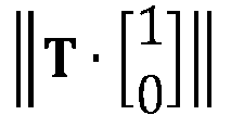
- ⁇ T ⁇ 1 0 ⁇ is a norm of a product of the matrix T and a matrix 1 0 .
- ⁇ * is the inclination angle
- the vector sum is a two-dimensional vector
- k(2) and k(1) are respectively the lengths of projections of the vector sum on the Y-axis and the X-axis of a level plane.
- the coordinate system transformation apparatus provided in the present embodiment of the present invention does not cause an asymmetric adjustment behavior rising in a flight attitude while improving gains of outer-loop control.
- an attitude estimation result of the aerial vehicle affects behaviors of the aerial vehicle in a symmetric manner. In this way, the designer of the controller of the aerial vehicle can have a direct understanding when designing the controller.
- the coordinate system transformation method is independent.
- the new expression of the inclination angle can only be used when transformation is performed between the north-east-down coordinate system and the control coordinate system.
- the aerial vehicle control method can still be compatible with or use the traditional Euler angle transformation matrix, and definitions of other angles of the Euler angle do not need to be correspondingly modified.
- the coordinate system transformation method can be conveniently added to a traditional aerial vehicle control system as an additional function module, thereby implementing more precise and better control performance.
- FIG. 10 is a schematic structural diagram of an unmanned aerial vehicle control system 100 according to an embodiment of the present invention.
- the unmanned aerial vehicle control system 100 includes one or more processors 110 and a memory 120.
- one processor 110 is used as an example.
- the unmanned aerial vehicle control system for performing the foregoing coordinate system transformation method may further include an input apparatus 130 and an output apparatus 140.
- an input apparatus 130 may be further included in the unmanned aerial vehicle control system for performing the foregoing coordinate system transformation method.
- output apparatus 140 may further include other appropriate modules.
- the processor 110, the memory 120, the input apparatus 130 and the output apparatus 140 may be connected by using a bus or in other forms.
- FIG. 10 shows an example in which connection is performed by using a bus.
- the memory 120 may be configured to store a non-volatile software program, a non-volatile computer executable program and a module, for example, the program instruction or the module corresponding to the coordinate system transformation method method in the embodiments of the present invention, for example, the unit vector obtaining module 910, the vector sum calculation module 920, the inclination angle representation module 930 and the coordinate system transformation module 940 shown in FIG. 9 .
- the processor 110 By running the non-volatile software program, the instruction and the module that are stored in the memory 120, the processor 110 performs various functional application and data processing of a server, that is, implements the coordinate system transformation method in the foregoing method embodiments.
- the memory 120 may include a program storage section and a data storage section.
- the program storage section may store an operating system and an application program needed by at least one function.
- the data storage section may store data created according to the use of the coordinate system transformation apparatus.
- the memory 120 may include a high speed random access memory, and may further include a non-volatile memory, such as at least one magnetic disk storage device, a flash memory, or other volatile solid-state storage devices.
- the memory 120 optionally includes a memory disposed remotely to the processor 110. Examples of the foregoing network include, but are not limited to, the Internet, an intranet, a local area network, a mobile communication network and a combination thereof.
- the input apparatus 130 may receive input digit or character information, and generate a key signal input related to the user setting and function control of the coordinate system transformation apparatus.
- the output apparatus 140 may include a display device such as a display screen.
- the one or more modules are stored in the memory 120 and when executed by the one or more processors 110, perform the coordinate system transformation method in any of the foregoing method embodiments.
- the steps of the coordinate system transformation method may be implemented by electronic hardware, computer software, or a combination thereof.
- the foregoing has generally described compositions and steps of each example according to functions. Whether the functions are performed in the form of hardware or software depends on the particular application of the technical solutions and the constraint conditions of the design.
- the computer software may be stored in a computer readable storage medium, and the program when executed, may include procedures of the foregoing method embodiments.
- the storage medium may be a magnetic disk, an optical disc, a read-only memory, a random access memory, or the like.
Landscapes
- Engineering & Computer Science (AREA)
- Physics & Mathematics (AREA)
- General Physics & Mathematics (AREA)
- Remote Sensing (AREA)
- Radar, Positioning & Navigation (AREA)
- Aviation & Aerospace Engineering (AREA)
- Automation & Control Theory (AREA)
- Mathematical Physics (AREA)
- Computational Mathematics (AREA)
- Theoretical Computer Science (AREA)
- Mathematical Analysis (AREA)
- Mathematical Optimization (AREA)
- Pure & Applied Mathematics (AREA)
- Data Mining & Analysis (AREA)
- Computing Systems (AREA)
- General Engineering & Computer Science (AREA)
- Software Systems (AREA)
- Databases & Information Systems (AREA)
- Algebra (AREA)
- Mechanical Engineering (AREA)
- Control Of Position, Course, Altitude, Or Attitude Of Moving Bodies (AREA)
Description
- The present invention relates to the field of heading control technologies for aerial vehicles, and in particular, to a coordinate system transformation method and apparatus, a heading control method for an aerial vehicle, and an aerial vehicle.
- During heading control of traditional aerial vehicles, there is a plurality of different coordinate systems, and a rigid body rotation representation method such as an Euler angle rotation transformation is needed to transform coordinate systems. An aerial vehicle can conveniently respond to a control signal by constructing a corresponding coordinate system in a speed vector control manner, so as to realize the change of the heading of the aerial vehicle.
- During implementation of the present invention, the inventor finds that the prior art has at least the following problems: There is asymmetry when transformation relationships between different coordinate systems is represented or defined by using a traditional Euler angle.
- Therefore, when control is performed based on the foregoing transformation relationship or mathematic representation method, control behaviors on the aerial vehicle are asymmetric and it is not intuitive in terms of human feelings. In addition, the precision of physical control over heading of the aerial vehicle is also limited.
- Document D1 (
US2013/173088 A1 ) discloses that the user inclines the apparatus (16) according to the pitch (32) and roll (34) axes to produce inclination signals (.theta..sub.I, .phi..sub.I) which are transformed into corresponding command setpoints (.theta..sub.d, .phi..sub.d) for the drone (10) in terms of attitude of the drone according to the pitch (22) and roll (24) axes of the drone. The drone and the apparatus each determine the orientation of their local reference frame (X.sub.lY.sub.lZ.sub.l; X.sub.bY.sub.bZ.sub.b) in relation to an absolute reference frame linked to the ground (X.sub.NEDY.sub.NEDZ.sub.NED), to determine the relative angular orientation of the drone in relation to the apparatus. Then, the reference frame of the apparatus is realigned on the reference frame of the drone by a rotation that is a function of this relative angular orientation. The realigned values thus correspond to user commands referenced in the reference frame of the apparatus and no longer in that of the drone, which allows for more intuitive piloting when the user is watching the drone. - To resolve the foregoing technical problems, embodiments of the present invention provide a heading control method for an aerial vehicle and an aerial vehicle.
- To resolve the foregoing technical problems, an embodiment of the present invention further provides the following technical solution: a heading control method for an aerial vehicle
- receiving a control instruction from a controller, the control instruction comprising at least one initial acceleration in a control coordinate system;
- transforming the initial acceleration in the control coordinate system to a first acceleration in the north-east-down coordinate system;
- transforming the first acceleration in the north-east-down coordinate system to a target acceleration of a body coordinate system by using an Euler angle rotation matrix; and
- controlling a motor of the aerial vehicle to operate according to the target acceleration;
- wherein the transforming the initial acceleration in the control coordinate system to the first acceleration in the north-east-down coordinate system comprises:
- obtaining an X-axis unit vector and a Y-axis unit vector of projections of an X-axis and a Y-axis of the body coordinate system on to a level plane of the north-east-down coordinate system, the body coordinate system being a coordinate system with the aerial vehicle as a coordinate origin;
- calculating a vector sum of the X-axis unit vector kx and the Y-axis unit vector k y ;
- representing an inclination angle by using the vector sum; and
- performing transformation between the north-east-down coordinate system and the control coordinate system by using the inclination angle;
- wherein the X-axis unit vector and the Y-axis unit vector are respectively calculated by using the following formulas;

- wherein T is a 2x2 matrix consisting of data taken from first two rows and first two columns of the Euler angle rotation matrix, kx is the X-axis unit vector, ky is the Y-axis unit vector and
- wherein the inclination angle is represented by using the following formula:

- wherein Ψ is the inclination angle, the vector sum is a two-dimensional vector, and k(2) and k(1) are respectively the length of projections of the vector sum on the Y-axis and the X-axis.
- A rotation sequence of the Euler angle rotation matrix is that the Euler angle rotation matrix sequentially rotates with respect to a roll axis, a heading axis and a pitch axis of the aerial vehicle.
- To resolve the foregoing technical problems, an embodiment of the present invention further provides the following technical solution: an unmanned aerial vehicle.
- The unmanned aerial vehicle includes a body, rotors, a motor for driving the rotors to rotate and a controller. The rotors are symmetrically disposed on the body; and the controller controls operation of the motor by using the heading control method for an aerial vehicle described above.
- In some embodiments, the unmanned aerial vehicle is a four-rotor aerial vehicle; and any two of the four rotors are symmetrically disposed with respect to the body.
- Compared with the prior art, the inclination angle is represented in the coordinate system transformation method provided in the embodiments of the present invention in a new manner, so that rotation transformation between the north-east-down (NED) coordinate system and the control coordinate system (stick frame) is symmetric, the precision of heading control of the aerial vehicle can be effectively improved, and a control behavior is more intuitive.
- One or more embodiments are exemplarily described by using figures that are corresponding thereto in the accompanying drawings. The exemplary descriptions do not constitute a limitation on the embodiments. Elements with a same reference numeral in the accompanying drawings represent similar elements. Unless otherwise particularly stated, the figures in the accompanying drawings constitute no proportional limitation.
-
FIG. 1 is a schematic diagram of an application environment according to an embodiment of the present invention; -
FIG. 2 is a schematic diagram of a geometric relationship between a north-east-down coordinate system and a control coordinate system; -
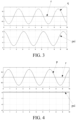
FIG. 3 shows a correlation between a pitch rate and an inclination angle when Φ = 20°; -
FIG. 4 shows a correlation between a roll rate and an inclination angle whenΘ = 20°; -
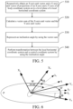
FIG. 5 is a schematic diagram of a coordinate system transformation method for an aerial vehicle according to an embodiment of the present invention; -
FIG. 6 is a schematic diagram of a geometric relationship between a north-east-down coordinate system and a body coordinate system according to an embodiment of the present invention; -
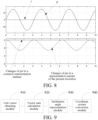
FIG. 7 shows a correlation between a pitch rate and an inclination angle when Φ = 20°according to a coordinate system transformation method provided in an embodiment of the present invention; -
FIG. 8 shows a correlation between a roll rate and an inclination angle on the premise thatΘ = 20° according to a coordinate system transformation method provided in an embodiment of the present invention; -
FIG. 9 is a block diagram of functions of a coordinate system transformation apparatus according to an embodiment of the present invention; and -
FIG. 10 is a schematic structural diagram of an unmanned aerial vehicle control system according to an embodiment of the present invention. - For ease of understanding the present invention, the present invention is described in further detail below with reference to the accompanying drawings and specific embodiments. It should be noted that when an element is described as being "fixed" on another element, the element may be directly on the another element, or one or more intermediate elements may exist therebetween. When an element is described as being "connected" to another element, the element may be directly connected to the another element, or one or more intermediate elements may exist therebetween. Directions and location relationships indicated by terms such as "upper", "lower", "inner", "outer" and "bottom" used in this specification are based on directions and location relationships shown in the accompanying drawings and are merely for ease of describing the present invention and simplifying descriptions rather than indicating or suggesting that a directed apparatus or element must have a specific direction and be constructed and operated in a specific direction, and therefore cannot be understood as a limitation on the present invention. In addition, terms such as "first", "second" and "third" are merely used for the purpose of description and cannot be understood as indicating or suggesting relative importance.
- Unless otherwise defined, meanings of all technical and scientific terms used in this specification are the same as that usually understood by a person skilled in the technical field to which the present invention belongs. The terms used in this specification of the present invention are merely intended to describe specific implementations rather than limit the present invention. A term "and/or" used in this specification includes any or all combinations of one or more related listed items.
- In addition, technical features involved in different embodiments of the present invention that are described below can be combined with each other provided that the technical features constitute no conflict.
-
FIG. 1 shows an application environment according to an embodiment of the present invention. As shown inFIG. 1 , the application environment includes an unmannedaerial vehicle 10, aremote control 20 and auser 30. - The unmanned
aerial vehicle 10 may be any type of unmanned aerial vehicles, for example, a four-axis unmanned aerial vehicle. The unmannedaerial vehicle 10 may specifically include several parts such as a body, rotors, a motor for driving the rotors to rotate and a controller. One or more motors operate under the control of the controller. A transmission mechanism drives the rotors to rotate to provide an acceleration in a corresponding direction for the unmanned aerial vehicle, so that the unmanned aerial vehicle completes various actions, for example, turning, accelerating, ascending or descending. - Specifically, as shown in
FIG. 1 , the unmanned aerial vehicle may be a four-rotor aerial vehicle. The four rotors are symmetrically disposed with respect to two axial directions of the body, and as four corners, the four rotors enclose a quadrangle having two symmetry axes. - The
remote control 20 may be any type of user device that establishes a communication connection to the unmannedaerial vehicle 10. Theremote control 20 is provided with one or more interaction devices such as a joystick, operation keys or a touchscreen which is configured to input a control instruction by theuser 30, to control the unmannedaerial vehicle 10 to perform different flying actions. - The control instruction input by the
user 30 is finally transformed to a corresponding acceleration provided for the controller of the motor. The controller of the motor controls the motor to operate to generate a corresponding acceleration. During operation in which heading of the aerial vehicle is controlled by a speed, a "control coordinate system" (stick frame) needs to be constructed. In this specification,O represents the "control coordinate system". In the coordinate system, an x-axis represents a heading direction of the aerial vehicle, and a y-axis represents a starboard direction of the aerial vehicle. - When the user applies a corresponding operation instruction on the remote control, for example, when the user expects to apply an acceleration a in an x-axis direction, the controller of the aerial vehicle first needs to transform the coordinate system to a "north-east-down coordinate system" (NED-frame), and then after the controller of the aerial vehicle transforms the coordinate system to corresponding vectors in a final "body coordinate system" (body frame) by using an Euler angle transformation method, the controller of the aerial vehicle can control the operating state of the motor and change the heading of the aerial vehicle.
-
FIG. 2 is a typical schematic diagram of a correlation between a north-east-down coordinate system and a control coordinate system. As shown inFIG. 2 , when a z-axis of the control coordinate system overlaps a z-axis of the north-east-down coordinate system, both an x-axis and a y-axis of the control coordinate system are in a level plane of the north-east-down coordinate system, and a relationship thereof may be represented by using an angle α between the x-axis and the north direction (N). - Generally, an angle α
O is represented by using an inclination angle Ψ of an Euler angle (a rotation matrix of the Euler angle rotates in a sequence of roll axis, heading axis and pitch axis, that is, in an x-y-z sequence). An expression of the inclination angle Ψ is represented by using the following formula (1):
- As can be seen from the formula (1), in a common expression of the inclination angle, the inclination angle depends only on a pitch rate r and a yaw rate q, but not on a roll rate p. Therefore, the inclination angle is obviously asymmetric.
- To further verify the asymmetry of a yaw angle caused by using a common mathematic expression, changes as a function of changes of a pitch angle may be observed when a roll angle is kept invariable, or changes as a function of changes of a roll angle may be observed when a pitch angle is kept invariable.
-
FIG. 3 shows a correlation between a pitch rate and an inclination angle Ψ (psi) on the premise that Φ = 20°.FIG. 4 shows a correlation between a roll rate and an inclination angle Ψ (psi) on the premise that Θ = 20°. - It should be noted that the experiment shown in
FIG. 3 and FIG. 4 are performed as a simulation in an ideal state, hence error in estimates were not considered. During actual control operations of the aerial vehicle, results may be different from those shown inFIG. 3 and FIG. 4 , but it doesn't affect the verification that asymmetry does exist during the adjustment of the inclination angle Ψ (psi). - The asymmetry that the inclination angle has causes a series of problems. Generally, power layouts of the aerial vehicle are symmetrically disposed with respect to an axis of the body. Therefore, during control of the aerial vehicle, it is expected to use symmetric mathematic expressions or control manners. Moreover, a symmetric coordinate system transformation manner makes heading control more intuitive for people.
- Embodiments of the present invention provide a new coordinate system transformation method. In this transformation method, the inclination angle is represented in a new manner, so that transformation between a control coordinate system and a north-east-down coordinate system is symmetric, which provides a better heading control effect of the aerial vehicle.
- As shown in
FIG. 5 , the coordinate system transformation method for an aerial vehicle includes the following steps:
510. Respectively obtain an X-axis unit vector and a Y-axis unit vector of projections of an X-axis and a Y-axis of a body coordinate system on to a level plane of a north-east-down coordinate system. - In the present embodiment, mutual transformation needs to be performed on three different coordinate systems: the body coordinate system, a north-east-down coordinate system and a control coordinate system.
- The body coordinate system is a coordinate system with the center of gravity of the aerial vehicle as a coordinate origin. The coordinate system is a basis for heading control of the aerial vehicle, and three axes of the coordinate system are respectively a pitch axis, a roll axis and a yaw axis. Finally, speed vectors output from the aerial vehicle are vectors represented in the body coordinate system.
- The north-east-down coordinate system (NED frame) is a coordinate system commonly used in navigation calculation. Three axes of the coordinate system respectively point to North, East and Down. By using the north-east-down coordinate system, the unmanned aerial vehicle can be conveniently controlled by means of speed vector.
- The control coordinate system (stick frame) is a planar coordinate system of locations of the aerial vehicle. The coordinate system is a reference of control instructions input by a user. An acceleration or a speed vector corresponding to a control instruction is based on the control coordinate system and needs to rotate and be transformed to the body coordinate system by using the Euler angle, so as to implement heading control during flying.
- 520. Calculate a vector sum of the X-axis unit vector and the Y-axis unit vector.
- The X-axis unit vector and the Y-axis unit vector are two two-dimensional vectors having a length unit of 1, representing corresponding directions of projections on to the level plane. The vector sum of the X-axis unit vector and the Y-axis unit vector is also a two-dimensional vector.
- 530. Represent an inclination angle by using the vector sum.
- Based on a three-dimensional geometric relationship between the two coordinate systems, a correlation between the vector sum and the inclination angle is determined. Based on the correlation, the inclination angle represented by using the vector sum may be obtained through derivation.
- 540. Perform transformation between the north-east-down coordinate system and a control coordinate system by using the inclination angle.
- After a new expression of the inclination angle is obtained, based on the new expression, mutual transformation is performed between the north-east-down coordinate system and the control coordinate system (to solve for an angle α
O ). - In the expression of the transformation relationship between the north-east-down coordinate system and the control coordinate system provided in the present embodiment, the sum of these two unit vectors would represent the heading in a more accurate sense by involving the contributions of both the x-axis and the y-axis and thereby assuring symmetry along both axes with regard to the flight performance, since during calculation of heading, each axis is considered.
- A construction process of the expression of the inclination angle is described in detail below with reference to a calculation principle diagram shown in
FIG. 6 . As shown inFIG. 6 , there are two different three-dimensional coordinate systems, which are respectively a body coordinate system B and a north-east-down coordinate system O. An X-axis and a Y-axis of the body coordinate system B are respectively represented by Xb and Yb and an X-axis and a Y-axis of the north-east-down coordinate system O are respectively represented by Xo and Yo. Xo and Yo form a level plane P. - A transformation relationship between the two coordinate systems is represented in a manner of rotation transformation by using the Euler angle (in a sequence of x-y-z). After sequentially rotating by three angles of Ψ, Θ, Φ with respect to the roll axis, the heading axis and the pitch axis, the coordinate system can be transformed from the north-east-down coordinate system O to the body coordinate system B. ky' is a reference line in a level plane of the north-east-down coordinate system, used for representing the anglesΘandΦ.
- Based on the foregoing coordinate system transformation relationship, projections of the Xb-axis and the Yb-axis of the body coordinate system B on the level plane of the north-east-down coordinate system and their respective unit vectors kx and ky are determined.
- kx is calculated by using a formula (2) and ky is calculated by using a formula (3):


- In the foregoing formula (1) and formula (2), T is a 2x2 matrix taken from the Euler angle rotation matrix.
- Specifically, T is a 2x2 matrix consisting of data taken from first two rows and first two columns of the Euler angle rotation matrix. The Euler angle rotation matrix is an Euler angle rotation matrix by using which the north-east-down coordinate system is transformed to the body coordinate system.
- That is, T is represented as follows by using a formula(4):

- M OB is an existing classical Euler angle rotation matrix that is very commonly used.
- Still referring to
FIG. 6 , the two unit vectors kx and ky are added to obtain a two-dimensional vector k in the level plane. In the present embodiment, the two-dimensional vector k is represented by (k1, k2), that is, the lengths of projections of the two-dimensional vector on an x-axis and a y-axis of the level plane. - The vector k is formed by adding the two unit vectors kx and ky. As a result, the vector k is introduced to the x-axis and the y-axis. According to the geometric relationship shown in
FIG. 6 , it is seen that a tan value of the two-dimensional vector k is equal to a sum of the inclination angle and 45°. Therefore, a mathematic expression of the inclination angle Ψ is obtained through derivation as shown in a formula (5):
- k(2) is the length of a projection of the two-dimensional vector k on the Y-axis of the level plane, and k(1) is the length of a projection of the two-dimensional vector k on the X-axis of the level plane.
-
FIG. 7 andFIG. 8 show correlations of angular rates and inclination angles of axes of the body coordinate system when the coordinate system transformation method provided in the embodiments of the present invention is applied. -
FIG. 7 shows a correlation between a pitch rate and an inclination angle (psi) on the premise that Φ = 20°.FIG. 8 shows a correlation between a roll rate and an inclination angle (psi) on the premise that Θ = 20°. - During actual operation, a heading angle that changes by means of oscillation generates corresponding vertical height changes in a height direction (the Z-axis) of the aerial vehicle, which can be seen from a comparison between
FIG. 3-4 andFIG. 7-8 . - In a traditional inclination angle expression, the changes in the vertical height completely unrelated to an angular rate on a roll axis. This means that although two states are visibly the same (for example, angles of other axes remain invariable and only the roll rate changes), results still change due to characteristics of representation by using the Euler angle. That is, representation of the traditional Euler angle causes asymmetry.
- However, when the expression provided in the present embodiment of the present invention is used, there may be similar control behaviors in different cases. In the definition of the transformation relationship between the coordinate systems, the projections of the X-axis and the Y-axis of the body coordinate system on the north-east-down coordinate system are introduced. Therefore, the definition or the transformation formula has symmetry, problems exist during transformation of the control coordinate system can be resolved and control behaviors are symmetric and intuitive.
- It should be noted that the coordinate system transformation method provided in the present embodiment of the present invention can also be applied to heading control of other types of moving devices in addition to the application environment of flying control of the unmanned aerial vehicle shown in
FIG. 1 , to resolve a problem of asymmetry that exists when rotation transformation is performed between coordinate systems by using the Euler angle. - An embodiment of the present invention further provides a coordinate system transformation apparatus.
FIG. 9 is a schematic structural diagram of the coordinate system transformation apparatus according to the present embodiment of the present invention. - As shown in
FIG. 9 , the coordinate system transformation apparatus for an aerial vehicle includes: a unitvector obtaining module 910, a vectorsum calculation module 920, an inclinationangle representation module 930 and a coordinatesystem transformation module 940. - The unit
vector obtaining module 910 is configured to obtain an X-axis unit vector and a Y-axis unit vector of projections of an X-axis and a Y-axis of a body coordinate system on to a level plane of a north-east-down coordinate system. The body coordinate system is a coordinate system with the aerial vehicle as a coordinate origin. - The vector
sum calculation module 920 is configured to calculate a vector sum of the X-axis unit vector and the Y-axis unit vector. The inclinationangle representation module 930 is configured to represent an inclination angle by using the vector sum. The coordinatesystem transformation module 940 is configured to perform transformation between the north-east-down coordinate system and a control coordinate system by using the inclination angle. - During actual operation, first, the unit
vector obtaining module 910 obtains a projected X-axis unit vector and Y-axis unit vector. Then, the vectorsum calculation module 930 calculates a vector sum of the two unit vectors, to obtain a two-dimensional vector. The inclinationangle representation module 930 represents an inclination angle based on the calculated vector sum. The coordinatesystem transformation module 940 performs transformation between the north-east-down coordinate system and the control coordinate system by using the inclination angle represented by using the vector sum and provides a symmetric and intuitive adjustment behavior. - In some embodiments, transformation is performed between the body coordinate system and the north-east-down coordinate system by using an Euler angle rotation matrix in a sequence of x-y-z. That is, a vector in the body coordinate system is transformed to a vector in the north-east-down coordinate system by using the Euler angle rotation matrix.
- Specifically, the unit vector obtaining module respectively calculates the X-axis unit vector and the Y-axis unit vector by using the following formulas:

- T is a 2x2 matrix consisting of data taken from first two rows and first two columns of the Euler angle rotation matrix, kx is the X-axis unit vector, ky is the Y-axis unit vector and


- More specifically, the inclination angle representation module represents the inclination angle by using the following formula:

- Ψ* is the inclination angle, the vector sum is a two-dimensional vector, and k(2) and k(1) are respectively the lengths of projections of the vector sum on the Y-axis and the X-axis of a level plane.
- On one hand, the coordinate system transformation apparatus provided in the present embodiment of the present invention does not cause an asymmetric adjustment behavior rising in a flight attitude while improving gains of outer-loop control. On the other hand, an attitude estimation result of the aerial vehicle affects behaviors of the aerial vehicle in a symmetric manner. In this way, the designer of the controller of the aerial vehicle can have a direct understanding when designing the controller.
- In the present embodiment, the coordinate system transformation method is independent. The new expression of the inclination angle can only be used when transformation is performed between the north-east-down coordinate system and the control coordinate system. When transformation is performed between the north-east-down coordinate system and the body coordinate system, the aerial vehicle control method can still be compatible with or use the traditional Euler angle transformation matrix, and definitions of other angles of the Euler angle do not need to be correspondingly modified.
- In this way, the coordinate system transformation method can be conveniently added to a traditional aerial vehicle control system as an additional function module, thereby implementing more precise and better control performance.
-
FIG. 10 is a schematic structural diagram of an unmanned aerialvehicle control system 100 according to an embodiment of the present invention. As shown inFIG. 10 , the unmanned aerialvehicle control system 100 includes one ormore processors 110 and amemory 120. InFIG. 10 , oneprocessor 110 is used as an example. - The unmanned aerial vehicle control system for performing the foregoing coordinate system transformation method may further include an
input apparatus 130 and anoutput apparatus 140. Certainly, other appropriate modules may be added or reduced according to a need of an actual case. - The
processor 110, thememory 120, theinput apparatus 130 and theoutput apparatus 140 may be connected by using a bus or in other forms.FIG. 10 shows an example in which connection is performed by using a bus. - As a non-volatile computer-readable storage medium, the
memory 120 may be configured to store a non-volatile software program, a non-volatile computer executable program and a module, for example, the program instruction or the module corresponding to the coordinate system transformation method method in the embodiments of the present invention, for example, the unitvector obtaining module 910, the vectorsum calculation module 920, the inclinationangle representation module 930 and the coordinatesystem transformation module 940 shown inFIG. 9 . By running the non-volatile software program, the instruction and the module that are stored in thememory 120, theprocessor 110 performs various functional application and data processing of a server, that is, implements the coordinate system transformation method in the foregoing method embodiments. - The
memory 120 may include a program storage section and a data storage section. The program storage section may store an operating system and an application program needed by at least one function. The data storage section may store data created according to the use of the coordinate system transformation apparatus. In addition, thememory 120 may include a high speed random access memory, and may further include a non-volatile memory, such as at least one magnetic disk storage device, a flash memory, or other volatile solid-state storage devices. In some embodiments, thememory 120 optionally includes a memory disposed remotely to theprocessor 110. Examples of the foregoing network include, but are not limited to, the Internet, an intranet, a local area network, a mobile communication network and a combination thereof. - The
input apparatus 130 may receive input digit or character information, and generate a key signal input related to the user setting and function control of the coordinate system transformation apparatus. Theoutput apparatus 140 may include a display device such as a display screen. The one or more modules are stored in thememory 120 and when executed by the one ormore processors 110, perform the coordinate system transformation method in any of the foregoing method embodiments. - A person skilled in the art may be further aware that, in combination with the examples described in the embodiments disclosed in this specification, the steps of the coordinate system transformation method may be implemented by electronic hardware, computer software, or a combination thereof. To clearly describe the interchangeability between the hardware and the software, the foregoing has generally described compositions and steps of each example according to functions. Whether the functions are performed in the form of hardware or software depends on the particular application of the technical solutions and the constraint conditions of the design.
- A person skilled in the art can accomplish the described functions by using different methods in each specific application, but this accomplishment shall not be deemed as going beyond the protection scope of the present invention. The computer software may be stored in a computer readable storage medium, and the program when executed, may include procedures of the foregoing method embodiments. The storage medium may be a magnetic disk, an optical disc, a read-only memory, a random access memory, or the like.
Claims (4)
- A heading control method for an aerial vehicle, comprising:receiving a control instruction from a controller, the control instruction comprising at least one initial acceleration in a control coordinate system;transforming the initial acceleration in the control coordinate system to a first acceleration in the north-east-down coordinate system;transforming the first acceleration in the north-east-down coordinate system to a target acceleration of a body coordinate system by using an Euler angle rotation matrix; andcontrolling a motor of the aerial vehicle to operate according to the target acceleration;wherein the transforming the initial acceleration in the control coordinate system to the first acceleration in the north-east-down coordinate system comprises:obtaining (510) an X-axis unit vector and a Y-axis unit vector of projections of an X-axis and a Y-axis of the body coordinate system on to a level plane of the north-east-down coordinate system, the body coordinate system being a coordinate system with the aerial vehicle as a coordinate origin;calculating (520) a vector sum of the X-axis unit vector kx and the Y-axis unit vector k y ;representing (530) an inclination angle by using the vector sum; andperforming (540) transformation between the north-east-down coordinate system and the control coordinate system by using the inclination angle;wherein the X-axis unit vector and the Y-axis unit vector are respectively calculated by using the following formulas;
 wherein T is a 2x2 matrix consisting of data taken from first two rows and first two columns of the Euler angle rotation matrix, kx is the X-axis unit vector, ky is the Y-axis unit vector and
 wherein the inclination angle is represented by using the following formula:
 wherein Ψ is the inclination angle, the vector sum is a two-dimensional vector, and k(2) and k(1) are respectively the length of projections of the vector sum on the Y-axis and the X-axis.
 - The heading control method according to claim 1, wherein a rotation sequence of the Euler angle rotation matrix is that the Euler angle rotation matrix sequentially rotates with respect to a roll axis, a heading axis and a pitch axis of the aerial vehicle.
- An unmanned aerial vehicle, characterized by comprising a body, rotors, a motor for driving the rotors to rotate and a controller, wherein the rotors are symmetrically disposed on the body; and
the controller controls operation of the motor by using the heading control method for an aerial vehicle according to any of claims 1-2. - The unmanned aerial vehicle according to claim 3, wherein the unmanned aerial vehicle is a four-rotor aerial vehicle; and any two of the four rotors are symmetrically disposed with respect to the body.
Priority Applications (2)
| Application Number | Priority Date | Filing Date | Title |
|---|---|---|---|
| EP18181402.1A EP3591337B1 (en) | 2018-07-03 | 2018-07-03 | Coordinate system transformation method and apparatus, heading control method for aerial vehicle, and aerial vehicle |
| CN201910585773.3A CN110282121B (en) | 2018-07-03 | 2019-07-01 | Coordinate system conversion method and device, aircraft course control method and aircraft |
Applications Claiming Priority (1)
| Application Number | Priority Date | Filing Date | Title |
|---|---|---|---|
| EP18181402.1A EP3591337B1 (en) | 2018-07-03 | 2018-07-03 | Coordinate system transformation method and apparatus, heading control method for aerial vehicle, and aerial vehicle |
Publications (2)
| Publication Number | Publication Date |
|---|---|
| EP3591337A1 EP3591337A1 (en) | 2020-01-08 |
| EP3591337B1 true EP3591337B1 (en) | 2024-05-15 |
Family
ID=62981000
Family Applications (1)
| Application Number | Title | Priority Date | Filing Date |
|---|---|---|---|
| EP18181402.1A Active EP3591337B1 (en) | 2018-07-03 | 2018-07-03 | Coordinate system transformation method and apparatus, heading control method for aerial vehicle, and aerial vehicle |
Country Status (2)
| Country | Link |
|---|---|
| EP (1) | EP3591337B1 (en) |
| CN (1) | CN110282121B (en) |
Families Citing this family (7)
| Publication number | Priority date | Publication date | Assignee | Title |
|---|---|---|---|---|
| CN113311422B (en) * | 2020-02-27 | 2024-09-24 | 富士通株式会社 | Coordinate conversion method, device and data processing equipment |
| CN111611742B (en) * | 2020-06-11 | 2022-03-18 | 上海卫星工程研究所 | Plane deformation absolute-relative Euler angle calculation method and system |
| CN113515201B (en) * | 2021-07-27 | 2024-03-19 | 北京字节跳动网络技术有限公司 | Cursor position update method, device and electronic device |
| CN116543040B (en) * | 2023-04-21 | 2024-09-10 | 成都飞机工业(集团)有限责任公司 | Aviation electric connector hole number identification method |
| CN119166087B (en) * | 2024-09-23 | 2025-05-09 | 北京世冠金洋科技发展有限公司 | Method and device for displaying simulated aircraft in three-dimensional earth model |
| CN121000287B (en) * | 2025-09-19 | 2026-04-07 | 蓝星光域(上海)航天科技有限公司 | Inter-satellite laser communication methods, systems, computer equipment, storage media, and software products for avoiding solar interference. |
| CN121141723B (en) * | 2025-11-14 | 2026-02-10 | 上海交通大学 | High-resolution spatial orientation mapping method and system for single-crystal EBSD |
Family Cites Families (5)
| Publication number | Priority date | Publication date | Assignee | Title |
|---|---|---|---|---|
| US7739014B2 (en) * | 2006-08-30 | 2010-06-15 | Ford Global Technolgies | Integrated control system for stability control of yaw, roll and lateral motion of a driving vehicle using an integrated sensing system to determine a final linear lateral velocity |
| GB2462452B (en) * | 2008-08-08 | 2011-02-02 | Univ Manchester | A rotary wing vehicle |
| FR2985329B1 (en) * | 2012-01-04 | 2015-01-30 | Parrot | METHOD FOR INTUITIVE CONTROL OF A DRONE USING A REMOTE CONTROL APPARATUS |
| CN104760695B (en) * | 2015-03-23 | 2017-09-29 | 松翰科技(深圳)有限公司 | A kind of method that four gyroplane controls are carried out using Vector Rotation method |
| WO2017185316A1 (en) * | 2016-04-29 | 2017-11-02 | 深圳市大疆创新科技有限公司 | First-person-view flight control method and system for unmanned aerial vehicle, and smart glasses |
-
2018
- 2018-07-03 EP EP18181402.1A patent/EP3591337B1/en active Active
-
2019
- 2019-07-01 CN CN201910585773.3A patent/CN110282121B/en active Active
Also Published As
| Publication number | Publication date |
|---|---|
| CN110282121B (en) | 2021-07-30 |
| EP3591337A1 (en) | 2020-01-08 |
| CN110282121A (en) | 2019-09-27 |
Similar Documents
| Publication | Publication Date | Title |
|---|---|---|
| EP3591337B1 (en) | Coordinate system transformation method and apparatus, heading control method for aerial vehicle, and aerial vehicle | |
| Ansari et al. | Quadrotor control via robust generalized dynamic inversion and adaptive non‐singular terminal sliding mode | |
| CN108919835B (en) | Control method and device for formation of unmanned aerial vehicles and controller | |
| Turpin et al. | Trajectory design and control for aggressive formation flight with quadrotors | |
| EP2845071B1 (en) | Three-dimensional manipulation of teams of quadrotors | |
| US7627404B2 (en) | Singularity escape and avoidance using a virtual array rotation | |
| CN109947126B (en) | Control method, device, device and readable medium for quadrotor unmanned aerial vehicle | |
| US20250091737A1 (en) | Aircraft attitude tracking control method, system and computer equipment | |
| KR102021498B1 (en) | Design method of attitude control system for flight vehicle and computer program | |
| CN113031636A (en) | Unmanned aerial vehicle control method and device, electronic equipment, unmanned aerial vehicle and storage medium | |
| Ghadiri et al. | Finite-time integral fast terminal sliding mode control for uncertain quadrotor UAV based on state-dependent Riccati equation observer subjected to disturbances | |
| Cariño et al. | A fully-actuated quadcopter representation using quaternions | |
| US7246776B2 (en) | Method and system for CMG array singularity avoidance | |
| González-Vázquez et al. | Motion control of a quadrotor aircraft via singular perturbations | |
| Braun et al. | Configuration assessment and preliminary control law design for a novel diamond-shaped UAV | |
| Ramos et al. | Factorized partial-update Schmidt–Kalman filter | |
| CN119739158A (en) | Multi-robot collaborative control method and device | |
| Martini | Koopman-Based Modeling for Nonlinear Control of Multirotor UAVs | |
| Mubdir et al. | Distributed nonlinear model predictive control for a quadrotor UAV | |
| Kovryzhenko | Application of the finite fourier series for smooth motion planning of quadrotors | |
| CN118244793A (en) | Vision-guided non-cooperative mobile platform aircraft dynamic landing control method | |
| Dargham et al. | Euler and quaternion parameterization in vtol uav dynamics with test model efficiency | |
| CN118484022B (en) | Unmanned aerial vehicle high maneuver control method and system in high dynamic strong countermeasure environment | |
| Goldschmid et al. | A Multi-Simulation Approach with Model Predictive Control for Anafi Drones | |
| CN119045517B (en) | An attitude control method and system for an amphibious dual-rotor unmanned aerial vehicle (UAV). |
Legal Events
| Date | Code | Title | Description |
|---|---|---|---|
| PUAI | Public reference made under article 153(3) epc to a published international application that has entered the european phase |
Free format text: ORIGINAL CODE: 0009012 |
|
| STAA | Information on the status of an ep patent application or granted ep patent |
Free format text: STATUS: THE APPLICATION HAS BEEN PUBLISHED |
|
| AK | Designated contracting states |
Kind code of ref document: A1 Designated state(s): AL AT BE BG CH CY CZ DE DK EE ES FI FR GB GR HR HU IE IS IT LI LT LU LV MC MK MT NL NO PL PT RO RS SE SI SK SM TR |
|
| AX | Request for extension of the european patent |
Extension state: BA ME |
|
| STAA | Information on the status of an ep patent application or granted ep patent |
Free format text: STATUS: REQUEST FOR EXAMINATION WAS MADE |
|
| 17P | Request for examination filed |
Effective date: 20200622 |
|
| RBV | Designated contracting states (corrected) |
Designated state(s): AL AT BE BG CH CY CZ DE DK EE ES FI FR GB GR HR HU IE IS IT LI LT LU LV MC MK MT NL NO PL PT RO RS SE SI SK SM TR |
|
| STAA | Information on the status of an ep patent application or granted ep patent |
Free format text: STATUS: EXAMINATION IS IN PROGRESS |
|
| 17Q | First examination report despatched |
Effective date: 20220830 |
|
| GRAP | Despatch of communication of intention to grant a patent |
Free format text: ORIGINAL CODE: EPIDOSNIGR1 |
|
| STAA | Information on the status of an ep patent application or granted ep patent |
Free format text: STATUS: GRANT OF PATENT IS INTENDED |
|
| INTG | Intention to grant announced |
Effective date: 20231207 |
|
| GRAS | Grant fee paid |
Free format text: ORIGINAL CODE: EPIDOSNIGR3 |
|
| GRAA | (expected) grant |
Free format text: ORIGINAL CODE: 0009210 |
|
| STAA | Information on the status of an ep patent application or granted ep patent |
Free format text: STATUS: THE PATENT HAS BEEN GRANTED |
|
| AK | Designated contracting states |
Kind code of ref document: B1 Designated state(s): AL AT BE BG CH CY CZ DE DK EE ES FI FR GB GR HR HU IE IS IT LI LT LU LV MC MK MT NL NO PL PT RO RS SE SI SK SM TR |
|
| REG | Reference to a national code |
Ref country code: CH Ref legal event code: EP Ref country code: GB Ref legal event code: FG4D |
|
| REG | Reference to a national code |
Ref country code: DE Ref legal event code: R081 Ref document number: 602018069440 Country of ref document: DE Owner name: AUTEL ROBOTICS EUROPE GMBH, DE Free format text: FORMER OWNER: ANMELDERANGABEN UNKLAR / UNVOLLSTAENDIG, 80297 MUENCHEN, DE Ref country code: DE Ref legal event code: R096 Ref document number: 602018069440 Country of ref document: DE |
|
| REG | Reference to a national code |
Ref country code: IE Ref legal event code: FG4D |
|
| REG | Reference to a national code |
Ref country code: LT Ref legal event code: MG9D |
|
| REG | Reference to a national code |
Ref country code: NL Ref legal event code: MP Effective date: 20240515 |
|
| PG25 | Lapsed in a contracting state [announced via postgrant information from national office to epo] |
Ref country code: IS Free format text: LAPSE BECAUSE OF FAILURE TO SUBMIT A TRANSLATION OF THE DESCRIPTION OR TO PAY THE FEE WITHIN THE PRESCRIBED TIME-LIMIT Effective date: 20240915 |
|
| PG25 | Lapsed in a contracting state [announced via postgrant information from national office to epo] |
Ref country code: BG Free format text: LAPSE BECAUSE OF FAILURE TO SUBMIT A TRANSLATION OF THE DESCRIPTION OR TO PAY THE FEE WITHIN THE PRESCRIBED TIME-LIMIT Effective date: 20240515 |
|
| PG25 | Lapsed in a contracting state [announced via postgrant information from national office to epo] |
Ref country code: FI Free format text: LAPSE BECAUSE OF FAILURE TO SUBMIT A TRANSLATION OF THE DESCRIPTION OR TO PAY THE FEE WITHIN THE PRESCRIBED TIME-LIMIT Effective date: 20240515 Ref country code: HR Free format text: LAPSE BECAUSE OF FAILURE TO SUBMIT A TRANSLATION OF THE DESCRIPTION OR TO PAY THE FEE WITHIN THE PRESCRIBED TIME-LIMIT Effective date: 20240515 |
|
| PG25 | Lapsed in a contracting state [announced via postgrant information from national office to epo] |
Ref country code: GR Free format text: LAPSE BECAUSE OF FAILURE TO SUBMIT A TRANSLATION OF THE DESCRIPTION OR TO PAY THE FEE WITHIN THE PRESCRIBED TIME-LIMIT Effective date: 20240816 |
|
| PG25 | Lapsed in a contracting state [announced via postgrant information from national office to epo] |
Ref country code: PT Free format text: LAPSE BECAUSE OF FAILURE TO SUBMIT A TRANSLATION OF THE DESCRIPTION OR TO PAY THE FEE WITHIN THE PRESCRIBED TIME-LIMIT Effective date: 20240916 |
|
| PGFP | Annual fee paid to national office [announced via postgrant information from national office to epo] |
Ref country code: GB Payment date: 20240725 Year of fee payment: 7 |
|
| REG | Reference to a national code |
Ref country code: AT Ref legal event code: MK05 Ref document number: 1687245 Country of ref document: AT Kind code of ref document: T Effective date: 20240515 |
|
| PG25 | Lapsed in a contracting state [announced via postgrant information from national office to epo] |
Ref country code: NL Free format text: LAPSE BECAUSE OF FAILURE TO SUBMIT A TRANSLATION OF THE DESCRIPTION OR TO PAY THE FEE WITHIN THE PRESCRIBED TIME-LIMIT Effective date: 20240515 |
|
| PG25 | Lapsed in a contracting state [announced via postgrant information from national office to epo] |
Ref country code: ES Free format text: LAPSE BECAUSE OF FAILURE TO SUBMIT A TRANSLATION OF THE DESCRIPTION OR TO PAY THE FEE WITHIN THE PRESCRIBED TIME-LIMIT Effective date: 20240515 |
|
| PG25 | Lapsed in a contracting state [announced via postgrant information from national office to epo] |
Ref country code: AT Free format text: LAPSE BECAUSE OF FAILURE TO SUBMIT A TRANSLATION OF THE DESCRIPTION OR TO PAY THE FEE WITHIN THE PRESCRIBED TIME-LIMIT Effective date: 20240515 |
|
| PG25 | Lapsed in a contracting state [announced via postgrant information from national office to epo] |
Ref country code: PL Free format text: LAPSE BECAUSE OF FAILURE TO SUBMIT A TRANSLATION OF THE DESCRIPTION OR TO PAY THE FEE WITHIN THE PRESCRIBED TIME-LIMIT Effective date: 20240515 |
|
| PG25 | Lapsed in a contracting state [announced via postgrant information from national office to epo] |
Ref country code: LV Free format text: LAPSE BECAUSE OF FAILURE TO SUBMIT A TRANSLATION OF THE DESCRIPTION OR TO PAY THE FEE WITHIN THE PRESCRIBED TIME-LIMIT Effective date: 20240515 |
|
| PG25 | Lapsed in a contracting state [announced via postgrant information from national office to epo] |
Ref country code: PT Free format text: LAPSE BECAUSE OF FAILURE TO SUBMIT A TRANSLATION OF THE DESCRIPTION OR TO PAY THE FEE WITHIN THE PRESCRIBED TIME-LIMIT Effective date: 20240916 Ref country code: PL Free format text: LAPSE BECAUSE OF FAILURE TO SUBMIT A TRANSLATION OF THE DESCRIPTION OR TO PAY THE FEE WITHIN THE PRESCRIBED TIME-LIMIT Effective date: 20240515 Ref country code: NO Free format text: LAPSE BECAUSE OF FAILURE TO SUBMIT A TRANSLATION OF THE DESCRIPTION OR TO PAY THE FEE WITHIN THE PRESCRIBED TIME-LIMIT Effective date: 20240815 Ref country code: NL Free format text: LAPSE BECAUSE OF FAILURE TO SUBMIT A TRANSLATION OF THE DESCRIPTION OR TO PAY THE FEE WITHIN THE PRESCRIBED TIME-LIMIT Effective date: 20240515 Ref country code: LV Free format text: LAPSE BECAUSE OF FAILURE TO SUBMIT A TRANSLATION OF THE DESCRIPTION OR TO PAY THE FEE WITHIN THE PRESCRIBED TIME-LIMIT Effective date: 20240515 Ref country code: IS Free format text: LAPSE BECAUSE OF FAILURE TO SUBMIT A TRANSLATION OF THE DESCRIPTION OR TO PAY THE FEE WITHIN THE PRESCRIBED TIME-LIMIT Effective date: 20240915 Ref country code: HR Free format text: LAPSE BECAUSE OF FAILURE TO SUBMIT A TRANSLATION OF THE DESCRIPTION OR TO PAY THE FEE WITHIN THE PRESCRIBED TIME-LIMIT Effective date: 20240515 Ref country code: GR Free format text: LAPSE BECAUSE OF FAILURE TO SUBMIT A TRANSLATION OF THE DESCRIPTION OR TO PAY THE FEE WITHIN THE PRESCRIBED TIME-LIMIT Effective date: 20240816 Ref country code: FI Free format text: LAPSE BECAUSE OF FAILURE TO SUBMIT A TRANSLATION OF THE DESCRIPTION OR TO PAY THE FEE WITHIN THE PRESCRIBED TIME-LIMIT Effective date: 20240515 Ref country code: ES Free format text: LAPSE BECAUSE OF FAILURE TO SUBMIT A TRANSLATION OF THE DESCRIPTION OR TO PAY THE FEE WITHIN THE PRESCRIBED TIME-LIMIT Effective date: 20240515 Ref country code: BG Free format text: LAPSE BECAUSE OF FAILURE TO SUBMIT A TRANSLATION OF THE DESCRIPTION OR TO PAY THE FEE WITHIN THE PRESCRIBED TIME-LIMIT Effective date: 20240515 Ref country code: AT Free format text: LAPSE BECAUSE OF FAILURE TO SUBMIT A TRANSLATION OF THE DESCRIPTION OR TO PAY THE FEE WITHIN THE PRESCRIBED TIME-LIMIT Effective date: 20240515 Ref country code: RS Free format text: LAPSE BECAUSE OF FAILURE TO SUBMIT A TRANSLATION OF THE DESCRIPTION OR TO PAY THE FEE WITHIN THE PRESCRIBED TIME-LIMIT Effective date: 20240815 |
|
| PG25 | Lapsed in a contracting state [announced via postgrant information from national office to epo] |
Ref country code: DK Free format text: LAPSE BECAUSE OF FAILURE TO SUBMIT A TRANSLATION OF THE DESCRIPTION OR TO PAY THE FEE WITHIN THE PRESCRIBED TIME-LIMIT Effective date: 20240515 |
|
| PG25 | Lapsed in a contracting state [announced via postgrant information from national office to epo] |
Ref country code: EE Free format text: LAPSE BECAUSE OF FAILURE TO SUBMIT A TRANSLATION OF THE DESCRIPTION OR TO PAY THE FEE WITHIN THE PRESCRIBED TIME-LIMIT Effective date: 20240515 |
|
| PG25 | Lapsed in a contracting state [announced via postgrant information from national office to epo] |
Ref country code: CZ Free format text: LAPSE BECAUSE OF FAILURE TO SUBMIT A TRANSLATION OF THE DESCRIPTION OR TO PAY THE FEE WITHIN THE PRESCRIBED TIME-LIMIT Effective date: 20240515 |
|
| PG25 | Lapsed in a contracting state [announced via postgrant information from national office to epo] |
Ref country code: SK Free format text: LAPSE BECAUSE OF FAILURE TO SUBMIT A TRANSLATION OF THE DESCRIPTION OR TO PAY THE FEE WITHIN THE PRESCRIBED TIME-LIMIT Effective date: 20240515 Ref country code: RO Free format text: LAPSE BECAUSE OF FAILURE TO SUBMIT A TRANSLATION OF THE DESCRIPTION OR TO PAY THE FEE WITHIN THE PRESCRIBED TIME-LIMIT Effective date: 20240515 |
|
| PG25 | Lapsed in a contracting state [announced via postgrant information from national office to epo] |
Ref country code: SM Free format text: LAPSE BECAUSE OF FAILURE TO SUBMIT A TRANSLATION OF THE DESCRIPTION OR TO PAY THE FEE WITHIN THE PRESCRIBED TIME-LIMIT Effective date: 20240515 |
|
| PG25 | Lapsed in a contracting state [announced via postgrant information from national office to epo] |
Ref country code: SM Free format text: LAPSE BECAUSE OF FAILURE TO SUBMIT A TRANSLATION OF THE DESCRIPTION OR TO PAY THE FEE WITHIN THE PRESCRIBED TIME-LIMIT Effective date: 20240515 Ref country code: SK Free format text: LAPSE BECAUSE OF FAILURE TO SUBMIT A TRANSLATION OF THE DESCRIPTION OR TO PAY THE FEE WITHIN THE PRESCRIBED TIME-LIMIT Effective date: 20240515 Ref country code: RO Free format text: LAPSE BECAUSE OF FAILURE TO SUBMIT A TRANSLATION OF THE DESCRIPTION OR TO PAY THE FEE WITHIN THE PRESCRIBED TIME-LIMIT Effective date: 20240515 Ref country code: EE Free format text: LAPSE BECAUSE OF FAILURE TO SUBMIT A TRANSLATION OF THE DESCRIPTION OR TO PAY THE FEE WITHIN THE PRESCRIBED TIME-LIMIT Effective date: 20240515 Ref country code: DK Free format text: LAPSE BECAUSE OF FAILURE TO SUBMIT A TRANSLATION OF THE DESCRIPTION OR TO PAY THE FEE WITHIN THE PRESCRIBED TIME-LIMIT Effective date: 20240515 Ref country code: CZ Free format text: LAPSE BECAUSE OF FAILURE TO SUBMIT A TRANSLATION OF THE DESCRIPTION OR TO PAY THE FEE WITHIN THE PRESCRIBED TIME-LIMIT Effective date: 20240515 |
|
| PG25 | Lapsed in a contracting state [announced via postgrant information from national office to epo] |
Ref country code: MC Free format text: LAPSE BECAUSE OF FAILURE TO SUBMIT A TRANSLATION OF THE DESCRIPTION OR TO PAY THE FEE WITHIN THE PRESCRIBED TIME-LIMIT Effective date: 20240515 Ref country code: IT Free format text: LAPSE BECAUSE OF FAILURE TO SUBMIT A TRANSLATION OF THE DESCRIPTION OR TO PAY THE FEE WITHIN THE PRESCRIBED TIME-LIMIT Effective date: 20240515 |
|
| REG | Reference to a national code |
Ref country code: DE Ref legal event code: R097 Ref document number: 602018069440 Country of ref document: DE |
|
| REG | Reference to a national code |
Ref country code: CH Ref legal event code: PL |
|
| PG25 | Lapsed in a contracting state [announced via postgrant information from national office to epo] |
Ref country code: LU Free format text: LAPSE BECAUSE OF NON-PAYMENT OF DUE FEES Effective date: 20240703 |
|
| PLBE | No opposition filed within time limit |
Free format text: ORIGINAL CODE: 0009261 |
|
| STAA | Information on the status of an ep patent application or granted ep patent |
Free format text: STATUS: NO OPPOSITION FILED WITHIN TIME LIMIT |
|
| PG25 | Lapsed in a contracting state [announced via postgrant information from national office to epo] |
Ref country code: LU Free format text: LAPSE BECAUSE OF NON-PAYMENT OF DUE FEES Effective date: 20240703 |
|
| 26N | No opposition filed |
Effective date: 20250218 |
|
| PG25 | Lapsed in a contracting state [announced via postgrant information from national office to epo] |
Ref country code: SI Free format text: LAPSE BECAUSE OF FAILURE TO SUBMIT A TRANSLATION OF THE DESCRIPTION OR TO PAY THE FEE WITHIN THE PRESCRIBED TIME-LIMIT Effective date: 20240515 Ref country code: CH Free format text: LAPSE BECAUSE OF NON-PAYMENT OF DUE FEES Effective date: 20240731 Ref country code: BE Free format text: LAPSE BECAUSE OF NON-PAYMENT OF DUE FEES Effective date: 20240731 |
|
| REG | Reference to a national code |
Ref country code: BE Ref legal event code: MM Effective date: 20240731 |
|
| PG25 | Lapsed in a contracting state [announced via postgrant information from national office to epo] |
Ref country code: IE Free format text: LAPSE BECAUSE OF NON-PAYMENT OF DUE FEES Effective date: 20240703 |
|
| PG25 | Lapsed in a contracting state [announced via postgrant information from national office to epo] |
Ref country code: SE Free format text: LAPSE BECAUSE OF FAILURE TO SUBMIT A TRANSLATION OF THE DESCRIPTION OR TO PAY THE FEE WITHIN THE PRESCRIBED TIME-LIMIT Effective date: 20240515 |
|
| PGFP | Annual fee paid to national office [announced via postgrant information from national office to epo] |
Ref country code: DE Payment date: 20250722 Year of fee payment: 8 |
|
| PGFP | Annual fee paid to national office [announced via postgrant information from national office to epo] |
Ref country code: FR Payment date: 20250725 Year of fee payment: 8 |
|
| PG25 | Lapsed in a contracting state [announced via postgrant information from national office to epo] |
Ref country code: CY Free format text: LAPSE BECAUSE OF FAILURE TO SUBMIT A TRANSLATION OF THE DESCRIPTION OR TO PAY THE FEE WITHIN THE PRESCRIBED TIME-LIMIT; INVALID AB INITIO Effective date: 20180703 |
|
| PG25 | Lapsed in a contracting state [announced via postgrant information from national office to epo] |
Ref country code: HU Free format text: LAPSE BECAUSE OF FAILURE TO SUBMIT A TRANSLATION OF THE DESCRIPTION OR TO PAY THE FEE WITHIN THE PRESCRIBED TIME-LIMIT; INVALID AB INITIO Effective date: 20180703 |
|
| GBPC | Gb: european patent ceased through non-payment of renewal fee |
Effective date: 20250703 |
|
| PG25 | Lapsed in a contracting state [announced via postgrant information from national office to epo] |
Ref country code: GB Free format text: LAPSE BECAUSE OF NON-PAYMENT OF DUE FEES Effective date: 20250703 |