EP3591294A1 - Combustor cooling and trim air profile control - Google Patents
Combustor cooling and trim air profile control Download PDFInfo
- Publication number
- EP3591294A1 EP3591294A1 EP19177570.9A EP19177570A EP3591294A1 EP 3591294 A1 EP3591294 A1 EP 3591294A1 EP 19177570 A EP19177570 A EP 19177570A EP 3591294 A1 EP3591294 A1 EP 3591294A1
- Authority
- EP
- European Patent Office
- Prior art keywords
- combustion liner
- aft
- seal
- combustion
- cooling
- Prior art date
- Legal status (The legal status is an assumption and is not a legal conclusion. Google has not performed a legal analysis and makes no representation as to the accuracy of the status listed.)
- Granted
Links
Images





Classifications
-
- F—MECHANICAL ENGINEERING; LIGHTING; HEATING; WEAPONS; BLASTING
- F23—COMBUSTION APPARATUS; COMBUSTION PROCESSES
- F23R—GENERATING COMBUSTION PRODUCTS OF HIGH PRESSURE OR HIGH VELOCITY, e.g. GAS-TURBINE COMBUSTION CHAMBERS
- F23R3/00—Continuous combustion chambers using liquid or gaseous fuel
- F23R3/02—Continuous combustion chambers using liquid or gaseous fuel characterised by the air-flow or gas-flow configuration
- F23R3/04—Air inlet arrangements
- F23R3/06—Arrangement of apertures along the flame tube
-
- F—MECHANICAL ENGINEERING; LIGHTING; HEATING; WEAPONS; BLASTING
- F23—COMBUSTION APPARATUS; COMBUSTION PROCESSES
- F23R—GENERATING COMBUSTION PRODUCTS OF HIGH PRESSURE OR HIGH VELOCITY, e.g. GAS-TURBINE COMBUSTION CHAMBERS
- F23R3/00—Continuous combustion chambers using liquid or gaseous fuel
- F23R3/02—Continuous combustion chambers using liquid or gaseous fuel characterised by the air-flow or gas-flow configuration
- F23R3/26—Controlling the air flow
-
- F—MECHANICAL ENGINEERING; LIGHTING; HEATING; WEAPONS; BLASTING
- F01—MACHINES OR ENGINES IN GENERAL; ENGINE PLANTS IN GENERAL; STEAM ENGINES
- F01D—NON-POSITIVE DISPLACEMENT MACHINES OR ENGINES, e.g. STEAM TURBINES
- F01D9/00—Stators
- F01D9/02—Nozzles; Nozzle boxes; Stator blades; Guide conduits, e.g. individual nozzles
- F01D9/023—Transition ducts between combustor cans and first stage of the turbine in gas-turbine engines; their cooling or sealings
-
- F—MECHANICAL ENGINEERING; LIGHTING; HEATING; WEAPONS; BLASTING
- F23—COMBUSTION APPARATUS; COMBUSTION PROCESSES
- F23R—GENERATING COMBUSTION PRODUCTS OF HIGH PRESSURE OR HIGH VELOCITY, e.g. GAS-TURBINE COMBUSTION CHAMBERS
- F23R3/00—Continuous combustion chambers using liquid or gaseous fuel
- F23R3/002—Wall structures
-
- F—MECHANICAL ENGINEERING; LIGHTING; HEATING; WEAPONS; BLASTING
- F23—COMBUSTION APPARATUS; COMBUSTION PROCESSES
- F23R—GENERATING COMBUSTION PRODUCTS OF HIGH PRESSURE OR HIGH VELOCITY, e.g. GAS-TURBINE COMBUSTION CHAMBERS
- F23R3/00—Continuous combustion chambers using liquid or gaseous fuel
- F23R3/005—Combined with pressure or heat exchangers
-
- F—MECHANICAL ENGINEERING; LIGHTING; HEATING; WEAPONS; BLASTING
- F23—COMBUSTION APPARATUS; COMBUSTION PROCESSES
- F23R—GENERATING COMBUSTION PRODUCTS OF HIGH PRESSURE OR HIGH VELOCITY, e.g. GAS-TURBINE COMBUSTION CHAMBERS
- F23R3/00—Continuous combustion chambers using liquid or gaseous fuel
- F23R3/02—Continuous combustion chambers using liquid or gaseous fuel characterised by the air-flow or gas-flow configuration
-
- F—MECHANICAL ENGINEERING; LIGHTING; HEATING; WEAPONS; BLASTING
- F23—COMBUSTION APPARATUS; COMBUSTION PROCESSES
- F23R—GENERATING COMBUSTION PRODUCTS OF HIGH PRESSURE OR HIGH VELOCITY, e.g. GAS-TURBINE COMBUSTION CHAMBERS
- F23R3/00—Continuous combustion chambers using liquid or gaseous fuel
- F23R3/02—Continuous combustion chambers using liquid or gaseous fuel characterised by the air-flow or gas-flow configuration
- F23R3/04—Air inlet arrangements
-
- F—MECHANICAL ENGINEERING; LIGHTING; HEATING; WEAPONS; BLASTING
- F23—COMBUSTION APPARATUS; COMBUSTION PROCESSES
- F23R—GENERATING COMBUSTION PRODUCTS OF HIGH PRESSURE OR HIGH VELOCITY, e.g. GAS-TURBINE COMBUSTION CHAMBERS
- F23R3/00—Continuous combustion chambers using liquid or gaseous fuel
- F23R3/42—Continuous combustion chambers using liquid or gaseous fuel characterised by the arrangement or form of the flame tubes or combustion chambers
- F23R3/46—Combustion chambers comprising an annular arrangement of several essentially tubular flame tubes within a common annular casing or within individual casings
-
- F—MECHANICAL ENGINEERING; LIGHTING; HEATING; WEAPONS; BLASTING
- F23—COMBUSTION APPARATUS; COMBUSTION PROCESSES
- F23R—GENERATING COMBUSTION PRODUCTS OF HIGH PRESSURE OR HIGH VELOCITY, e.g. GAS-TURBINE COMBUSTION CHAMBERS
- F23R3/00—Continuous combustion chambers using liquid or gaseous fuel
- F23R3/42—Continuous combustion chambers using liquid or gaseous fuel characterised by the arrangement or form of the flame tubes or combustion chambers
- F23R3/60—Support structures; Attaching or mounting means
-
- F—MECHANICAL ENGINEERING; LIGHTING; HEATING; WEAPONS; BLASTING
- F05—INDEXING SCHEMES RELATING TO ENGINES OR PUMPS IN VARIOUS SUBCLASSES OF CLASSES F01-F04
- F05D—INDEXING SCHEME FOR ASPECTS RELATING TO NON-POSITIVE-DISPLACEMENT MACHINES OR ENGINES, GAS-TURBINES OR JET-PROPULSION PLANTS
- F05D2260/00—Function
- F05D2260/20—Heat transfer, e.g. cooling
-
- F—MECHANICAL ENGINEERING; LIGHTING; HEATING; WEAPONS; BLASTING
- F23—COMBUSTION APPARATUS; COMBUSTION PROCESSES
- F23R—GENERATING COMBUSTION PRODUCTS OF HIGH PRESSURE OR HIGH VELOCITY, e.g. GAS-TURBINE COMBUSTION CHAMBERS
- F23R2900/00—Special features of, or arrangements for continuous combustion chambers; Combustion processes therefor
- F23R2900/00012—Details of sealing devices
-
- F—MECHANICAL ENGINEERING; LIGHTING; HEATING; WEAPONS; BLASTING
- F23—COMBUSTION APPARATUS; COMBUSTION PROCESSES
- F23R—GENERATING COMBUSTION PRODUCTS OF HIGH PRESSURE OR HIGH VELOCITY, e.g. GAS-TURBINE COMBUSTION CHAMBERS
- F23R2900/00—Special features of, or arrangements for continuous combustion chambers; Combustion processes therefor
- F23R2900/03045—Convection cooled combustion chamber walls provided with turbolators or means for creating turbulences to increase cooling
-
- Y—GENERAL TAGGING OF NEW TECHNOLOGICAL DEVELOPMENTS; GENERAL TAGGING OF CROSS-SECTIONAL TECHNOLOGIES SPANNING OVER SEVERAL SECTIONS OF THE IPC; TECHNICAL SUBJECTS COVERED BY FORMER USPC CROSS-REFERENCE ART COLLECTIONS [XRACs] AND DIGESTS
- Y02—TECHNOLOGIES OR APPLICATIONS FOR MITIGATION OR ADAPTATION AGAINST CLIMATE CHANGE
- Y02T—CLIMATE CHANGE MITIGATION TECHNOLOGIES RELATED TO TRANSPORTATION
- Y02T50/00—Aeronautics or air transport
- Y02T50/60—Efficient propulsion technologies, e.g. for aircraft
Definitions
- This disclosure relates to gas turbine engines and, in particular, to a combustion liner for a gas turbine engine, and a system for combustor cooling and/or trim air profile control.
- Gas turbine engines may include a compressor, a combustor, and a turbine.
- the compressor is an air compressor rotating on a shaft of the engine to provide air for the combustion cycle.
- Parts of the turbine may be subject to relatively high temperatures, such as from exhaust gas discharged by the combustor.
- a cooling fluid such as cooling air, may be used to cool parts of the turbine.
- Such cooling fluid may be supplied from the compressor, from another part of the gas turbine engine, or from an air supply external to the gas turbine engine.
- the present disclosure provides a combustion liner for a gas turbine engine, a system, and a method, as set out in the appended claims.
- the present disclosure provides a combustion liner for a gas turbine engine, the combustion liner comprising: a seal engagement region configured to couple with an aft seal; a plurality of cooling passages in the seal engagement region; a plurality of inlets to the cooling passages, the inlets located on an outer surface of the combustion liner; and a plurality of outlets for the cooling passages, the outlets located on an inner surface of the combustion liner in the seal engagement region, wherein the inner surface is configured to face radially inward toward a combustion chamber, and the outer surface is configured to face radially outward relative to the combustion chamber.
- the inlets may be located on a curved section of the outer surface of the combustion liner, where the curved section may curve radially outward from the inner surface of the combustion liner.
- the combustion liner may further comprise a plurality of trim hole inlets on the outer surface of the combustion liner, wherein the inlets to the cooling passageways may have a larger cross-sectional area than the trim hole inlets.
- Each of the inlets may open into a corresponding cylindrical cooling passage, the corresponding cylindrical cooling passage may be disposed within the combustion liner at an angle relative to the inner surface, the corresponding cylindrical cooling passage may expand into a supply passageway that has a substantially rectangular cross-section and may extend substantially parallel to the inner surface of the combustion liner in an aft direction, and the supply passageway may be included within the seal engagement region.
- the combustion liner may further comprise at least one pedestal disposed in at least one of the cooling passages.
- the combustion liner may be a double wall component comprising an outer wall that includes the outer surface and an inner wall that includes the inner surface, the pedestal may be coupled at a first end to the outer wall and a second end to the inner wall.
- a distance from a corresponding one of the outlets to an aft end surface of the combustion liner divided by a thickness of the combustion liner at the corresponding one of the outlets may be in a range of 1 ⁇ 2 to 1 ⁇ 4, and optionally the combustion liner may be at least an aft end of combustor tile.
- the present disclosure provides a system comprising: a combustion liner configured to be included in an aft end of a combustor for a gas turbine engine; and an aft seal movably engaged with the combustion liner in a seal engagement region, wherein the combustion liner comprises an inlet formed in an outer surface of the combustion liner to receive a cooling fluid, and an outlet in fluid communication with the inlet via a passageway formed within the combustion liner, the outlet disposed in an inner surface of the combustion liner in the seal engagement region.
- the combustion liner of the system may be a combustion liner of the first aspect.
- the outlet of the system may be configured (a) to direct a stream of the cooling fluid into an exhaust gas stream in a primary gas flow path of the gas turbine engine, or (b) to direct a stream of the cooling fluid beyond an aft end of the combustion liner.
- the combustion liner may comprise trim holes and the inlet that is in fluid communication with the outlet may be further aft than the trim holes.
- the inlet may be outside of the seal engagement region, and the passageway in the seal engagement region may include a supply passageway that is substantially parallel to the inner surface of the combustion liner.
- At least a portion of the aft seal may be nested inside of the combustion liner and the outlet may be radially inward from the portion of the aft seal nested inside the combustion liner.
- the inlet may comprise a plurality of inlets in fluid communication with the passageway, and the outlet may comprise a series of slots in fluid communication with the passageway.
- the present disclosure provides a method comprising: receiving a cooling fluid at an inlet on an outer surface of a combustion liner for a combustor of a gas turbine engine; directing the cooling fluid through a passageway located in the combustion liner radially inward of an aft seal that overlaps the combustion liner; and directing the cooling fluid from the passageway through an outlet of the combustion liner into a primary gas flow path, wherein the outlet is located radially inward of the aft seal.
- the combustion liner in the method may be a combustion liner of the first aspect.
- receiving the cooling fluid may comprise receiving the cooling fluid at a curved section of the outer surface, wherein the curved section may be curved further away from an inner surface of the combustion liner in an aft direction than in a fore direction.
- Directing the cooling fluid into the primary gas flow path may include injecting the cooling fluid beyond an aft end of the combustion liner.
- the method may further comprise routing the cooling fluid in the passageway around a pedestal included in the passageway.
- a combustion liner for a gas turbine engine may be provided.
- the combustion liner may include: a seal engagement region configured to couple with an aft seal; a plurality of cooling passages in the seal engagement region; a plurality of inlets to the cooling passages, the inlets located on an outer surface of the combustion liner; and a plurality of outlets for the cooling passages, the outlets located on an inner surface of the combustion liner in the seal engagement region, wherein the inner surface is configured to face radially inward toward a combustion chamber, and the outer surface is configured to face radially outward relative to the combustion chamber
- FIG. 1 is a cross-sectional view of a gas turbine engine 100.
- the gas turbine engine 100 may supply power to and/or provide propulsion of an aircraft.
- the aircraft may include a helicopter, an airplane, an unmanned space vehicle, a fixed wing vehicle, a variable wing vehicle, a rotary wing vehicle, an unmanned combat aerial vehicle, a tailless aircraft, a hover craft, and any other airborne and/or extraterrestrial (spacecraft) vehicle.
- the gas turbine engine 100 may be utilized in a configuration unrelated to an aircraft such as, for example, an industrial application, an energy application, a power plant, a pumping set, a marine application (for example, for naval propulsion), a weapon system, a security system, and a perimeter defense or security system.
- an industrial application for example, an industrial application, an energy application, a power plant, a pumping set, a marine application (for example, for naval propulsion), a weapon system, a security system, and a perimeter defense or security system.
- the gas turbine engine 100 may take a variety of forms in various embodiments. Though depicted as an axial flow engine in FIG. 1 , in some forms the gas turbine engine 100 may have multiple spools and/or may be a centrifugal or mixed centrifugal/axial flow engine. In some forms, the gas turbine engine 100 may be a turboprop, a turbofan, or a turboshaft engine. Furthermore, the gas turbine engine 100 may be an adaptive cycle and/or variable cycle engine. Other variations are also contemplated.
- the gas turbine engine 100 may include an intake section 120, a compressor section 160, a combustion section 130, a turbine section 110, and an exhaust section 150.
- fluid received from the intake section 120 such as air, travels along the direction D1 and may be compressed within the compressor section 160.
- the compressed fluid may then be mixed with fuel and the mixture may be burned in the combustion section 130.
- the combustion section 130 may include any suitable fuel injection and combustion mechanisms.
- the hot, high pressure fluid may then pass through the turbine section 110 to extract energy from the fluid and cause a turbine shaft of a turbine 114 in the turbine section 110 to rotate, which in turn drives the compressor section 160.
- Discharge fluid may exit the exhaust section 150.
- the hot, high pressure fluid passes through the turbine section 110 during operation of the gas turbine engine 100.
- the fluid passes between adjacent blades 112 of the turbine 114 causing the turbine 114 to rotate.
- the rotating turbine 114 may turn a shaft 140 in a rotational direction D2, for example.
- the blades 112 may rotate around an axis of rotation, which may correspond to a centerline X of the turbine 114 in some examples.
- a system for combustor cooling and trim air profile control may be located in an area 180 of the gas turbine engine 100 where the hot, high pressure fluid passes from a combustion chamber 104 of the combustion section 130 into the turbine section 110.
- An example of the system 102 for combustor cooling and trim air profile control is illustrated in FIGS. 2-7 .
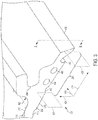
- FIG. 2 is a cross-sectional view of an aft end of a combustion liner 202 and an aft seal 204 movably engaged with the combustion liner 202 in a seal engagement region 206.
- the seal engagement region 206 may include a portion of the combustion liner 202 configured to engage or otherwise couple to the aft seal 204.
- the combustion liner 202 is a component that may contain the combustion process. Alternatively or in addition, the combustion liner 202 may introduce one or more airflows such as cooling air.
- the combustion liner 202 may define at least part of the combustion chamber 104.
- the combustion liner 202 may be made of any material suitable to withstand the relatively high temperatures resulting from combustion of fuel, such as a metal alloy, a superalloy, and/or a ceramic matrix composite.
- the aft seal 204 may couple to a high-pressure vane (not shown) located in the turbine section 110.
- a hot side 210 of the combustion liner 202 is called “hot” because the hot side 210 is designed to face the combustion chamber 104 through which relatively hot gasses flow along a primary gas flow path 208.
- a cold side 212 of the combustion liner 202 is called “cold” because the cold side 212 is designed to have cooling fluid 214, such as cooling air, flow along the cold side 212. Accordingly, the adjectives "hot” and “cold” used in connection with the terms “hot side” and “cold side”, respectively, refer to relative position, not to temperatures.
- the hot side 210 may be referred to as an inner surface of the combustion liner 202 because the hot side 210 is configured to face radially inward toward the combustion chamber 104.
- the cold side 212 may be referred to as an outer surface of the combustion liner 202 because the cold side 212 is configured to face radially outward relative to the combustion chamber 104.
- the aft seal 204 is component configured to limit or prevent the cold air from escaping between the combustion liner 202 and the high-pressure vane located in the turbine section 110.
- the seal engagement region 206 may be a portion of the combustion liner 202 configured to engage or otherwise couple to the aft seal 204.
- FIG. 3 is a perspective view of the aft end of the combustion liner 202.
- the aft seal 204 is not shown in FIG. 2 so that features of the combustion liner 202 are not obscured by the aft seal 204.
- the cross-sectional view of the combustion liner 202 shown in FIG. 2 is the cross-section indicated by arrows A and B in FIG. 3 .
- FIG. 4 is a perspective view of cooling passages 402, which are inside of the aft end of the combustion liner 202.
- the cooling passages 402 include inlets 404 and outlets 406.
- the cooling passages 402 are largely hidden from view in FIGS. 2-3 . However, one of the outlets 406 is visible in FIGS. 2-3 .
- portions 408 of the cooling passageways 402 that intersect the cross-section indicated by arrows A and B are shown in FIGS. 2-3 .
- FIG. 6 is a perspective view of the aft end of the combustion liner 202 showing the hot side 210 of the combustion liner 202.
- the portion of the combustion liner 202 shown in FIG. 6 is a corner of a tile.
- the cooling passages 402 are largely hidden from view.
- the outlets 406, which are located on the hot side 210 of the combustion liner 202 are clearly visible. Only a subset of the outlets 406 shown in FIG. 6 are indicated by lead lines. Also visible in FIG. 6 are openings 608 into the cooling passageways 402, which are on an edge side 602 of the tile.
- the edge side 602 of the tile is configured to abut an adjacent tile that has corresponding openings, which align with the openings 608 on the edge side 602 of the tile shown in FIG. 6 .
- Multiple tiles like the one shown in FIG. 6 may be arranged to form a complete annular combustion liner.
- FIG. 7 is a perspective view of the aft end of the combustion liner 202 showing the cold side 212 of the combustion liner 202.
- the portion of the combustion liner 202 shown in FIG. 7 is a complete aft end of a tile.
- the cooling passages 402 are hidden from view except for the inlets 404. Only a subset of the inlets 404 shown in FIG. 7 are indicated by lead lines. In the illustrated example, the inlets 404 are located on a curved section 702 on the cold side 212 of the combustion liner 202.
- cooling fluid 214 flows along the cold side 212 of the combustion liner 202 in an aft direction.
- the cooling fluid 214 approaches the curved section 702 of the combustion liner 20 and then enters the inlets 404 located on the curved section 702.
- the cooling fluid 214 flows through the cooling passages 402 in the combustion liner 202.
- the cooling fluid 214 cools the combustion liner 202 in the seal engagement region 206.
- the cooling fluid 214 exits the combustion liner 202 through the outlets 406.
- the cooling fluid 214 that exits through the outlets 406 cools the gases in the primary gas flow path 208.
- the cooling fluid 214 that exits through the outlets 406 acts as trim air that affects the combustor exit temperature profile.
- Design requirements may stipulate the shape of the temperature profile of gasses exiting the combustor in the primary gas flow path 208. For example, lowering the temperature of the gases in radially outer regions of the primary gas flow path 208 in the turbine section 110 may help prolong the life of the blades 112 and/or vanes in the turbine section 110.
- the speed, quantity, and/or angle of the cooling fluid 214 that exits the outlets 406, and/or the size and shape of the outlets 406 may be selected to control the trim air and, consequently, the shape of the temperature profile of gasses exiting the combustor and entering the turbine section 110.
- trim air jet penetration may be increased by decreasing a ratio of the area of the outlets 406 to the area of the inlets 404.
- decreasing the ratio of the area of the outlets 406 to the area of the inlets 404 may increase the momentum of the cooling fluid 214 exiting the outlets 406, thus increasing trim air jet penetration.
- increasing the ratio of the area of the outlets 406 to the area of the inlets 404 may decrease trim jet penetration.
- trim air jet penetration may be increased by steepening the angle of the cooling passages 402 at the outlets 406.
- Steepening the angle of the cooling passages 402 at the outlets 406 means orienting the cooling passages 402 to eject the cooling fluid 214 closer to a radially inward direction, which is perpendicular to the primary gas flow path 208.
- Trim holes which have trim hole inlets 710 on the cold side 212 of the combustion liner 202 and trim hole outlets 610 on the hot side 210 of the combustion liner 202, may also control the trim air and, consequently, the shape of the temperature profile of gasses exiting the combustor and entering the turbine section 110. Not all of the trim hole inlets 710 and the trim hole outlets 610 are indicated with lead lines in FIGS. 6 and 7 .
- the trim hole outlets 610 may be larger than the trim hole inlets 710 in some examples, such as the example illustrated in FIGS 2-7 .
- the trim holes may be angled with respect to the cold side 212 and/or the hot side 210.
- the trim holes may be machined, for example by drilling, into the combustion liner 202.
- the trim holes cannot extend the trim air cooling effect to the end of the combustion liner 202 because structures in the seal engagement region 206, such as the aft seal 204 and the portion of the combustion liner 202 that engages the aft seal 204, may get in the way. For example, even drilling the trim holes at an angle may be insufficient to reach into the seal engagement region 206 and/or to position the trim hole outlets 610 as far aft as the outlets 406 of the cooling passages 402 discussed earlier above.
- the cooling passages 402 may use less of the cooling fluid 214 with the cooling passages 402 to obtain a target temperature profile than without the cooling passages 402. Using less cooling fluid for cooling allows more to be used for combustion, which may be more and more important for high performance, high thrust engines.
- each of the inlets 404 opens into a corresponding cylindrical cooling passage 410, which is angled down into the combustion liner 202 and toward the seal engagement region 206.
- the corresponding cylindrical cooling passage 410 expands into a supply passageway 412 that has a substantially rectangular cross-section and extends substantially parallel to the hot side 210 of the combustion liner 202 in an aft direction 414.
- Adjacent supply passageways 412 are connected via oval passageways 416 that extend in a circumferential direction 418, which is substantially perpendicular to the aft direction 414 (not all of the oval passageways 416 are indicated by lead lines in FIG. 4 ).
- An array of pedestals 420 are located in the supply passageways 412 and between adjacent supply passageways 412 (not all of the pedestals 420 are indicated by lead lines in FIG. 4 ).
- the pedestals 420 that are located between any two adjacent supply passageways 412 may define, at least in part, the oval passageways 416 that connect the two adjacent supply passageways 412.
- the pedestals 420 help maintain the structural integrity of the combustion liner 202 and also aid in increasing the cooling effect of the cooling fluid 214 that flows through the cooling passageways 412.
- the supply passageways 412 lead into exit passageways 422, which in turn lead to the outlets 406. Accordingly, the exit passageways 422 are angled toward the hot side 210 of the combustion liner 202 in the aft direction 414. Each of the exit passageways 422 and corresponding one of the outlets 406 are located between two corresponding adjacent supply passageways 412 (and, therefore, between two corresponding adjacent inlets 404). In other words, the inlets 404 and the outlets 406 are offset from one another.
- exit passageways 422 and/or the corresponding outlets 406 may be in the form of a series of slots. Alternatively, the exit passageways 422 and/or the outlets 406 may be cylindrical or any other suitable shape.
- the system 102 for combustor cooling and trim air profile control may be implemented in many different ways.
- the system 102 may include only the part of the aft end of the combustion liner 202 that includes the cooling passageways 402 in the seal engagement region 206.
- the system 102 may include only a combustion liner tile that includes the cooling passageways 402 in the seal engagement region 206.
- the system 102 may include the combustion liner 202, which includes a complete annular combustion liner or a subset thereof, wherein the cooling passageways 402 are in the seal engagement region 206 of the combustion liner 202.
- the system 102 may include one or more components in addition to combustion liner 202, such as the aft seal 204.
- the combustion liner 202 is part of an annular combustion chamber.
- a combustion liner for an annular combustion chamber includes an outer combustion liner and an inner combustion liner.
- the combustion liner 202 may be an outer combustion liner if the hot side 210 of the combustion liner 202 faces radially inward toward the centerline X of the gas turbine engine 100, and if the cold side 212 of the combustion liner 202 faces radially outward from the centerline X.
- the combustion liner 202 may be an inner combustion liner if the hot side 210 of the combustion liner 202 faces radially outward away from the centerline X of the gas turbine engine 100, and if the cold side 212 of the combustion liner 202 faces radially inward toward the centerline X.
- the aft end of the inner combustion liner may have, in some examples, the same structure as the outer combustion liner but inverted. Alternatively, the structure of the aft end of the inner combustion liner may be different than the outer combustion liner.
- the combustion liner 202 is part of a can-annular combustor.
- a can-annular combustor may comprise an annular outer shell and a number of individual cylindrical liners mounted about the centerline X of the gas turbine engine 100.
- the combustion liner 202 such as the one illustrated in FIGS. 2-7 , may be any of the cylindrical liners for a can-annular combustor.
- the inlets 404 are located in the curved section 702 on the cold side 212 of the combustion liner 202. Moving in the aft direction 414 along the curved section 702, the cold side 212 on the curved section 702 curves away from the hot side 210. The curved section 702 may aid in directing the cooling fluid 214 into the inlets 404. Alternatively, the inlets 404 may not be located on a curved section 702 on the cold side 212. More generally, the inlets 404 to the cooling passageways 402 are formed in the cold side 212 of the combustion liner 202 and are configured to receive the cooling fluid 214.
- the inlets 404 and/or the outlets 406 may be arranged uniformly, irregularly, or a combination thereof, in the circumferential direction 418.
- the inlets 404 and/or the outlets 406 may be oriented in any direction relative to the cold side 212 and the hot side 210, respectively.
- the cooling passageways 402 may have any suitable structure and, therefore, be different than illustrated in FIGS. 2-7 .
- corresponding pairs of the inlets 404 and the outlets 406 may be aligned along an axial axis instead of being offset from each other as shown in FIG. 4 .
- the cooling passageways 402 may not include the oval passageways 416 that extend in the circumferential direction 418 and connect the adjacent supply passageways 412.
- each of the supply passageways 412 may be a discrete passageway, unconnected to any of the other supply passageways 412.
- the combustion liner 202 may not include the openings 608 on the edge side 602 of the tile to the cooling passageways 402.
- the combustion liner 202 may not include the pedestals 420.
- the supply passageways 412 may connect a corresponding one of the inlets 404 with a corresponding one of the outlets 406 without including any pedestal on the path from the inlet 404 to the outlet 406.
- the shapes and/or dimensions of the cooling passages 402 may vary from example to example.
- the seal engagement region 206 may be a portion of the combustion liner 202 that is configured to engage or otherwise couple to the aft seal 204.
- the portion of the combustion liner 202 that is included in the seal engagement region 206 may be any portion bounded by a first plane 426 and a second plane 428, where the first plane 426 is parallel to the second plane 428, where the first plane 426 and the second plane 428 are perpendicular to an axis that extends in the aft direction 414, where the first plane 426 intersects a point 430 at which the combustion liner 202 is configured to contact or engage the aft seal 204, and where the second plane 428 intersects an end surface 432 of the combustion liner 202 configured to face the aft direction 414.
- the first and second planes 426 may be parallel to an axis 424 that extends radially from a longitudinal axis of the combustion liner 202.
- the axis 424 that extends radially from the longitudinal axis is perpendicular to both the axis that extends in the aft direction 414 and an axis that extends in the circumferential direction 418.
- the seal engagement region 206 may be the portion of the combustion liner 202 between the end surface 432 and a point on the hot side 210 that cannot be reached by drilling a trim hole from the cold side 212 further to the fore (opposite of the aft direction 414) than the curved section 702.
- the seal engagement region 206 may be the portion of the combustion liner 202 that is radially inward from a portion of the combustion liner 202 that receives and/or abuts the aft seal 204.
- the combustion liner 202 and the aft seal 204 may overlap in the seal engagement region 206 such that one or more of the outlets 406 are radially inward of at least part of the aft seal 204.
- the seal engagement region 206 may have an entirely different structure than the example illustrated in FIGS. 2-7 .
- the structure of the seal engagement region 206 may vary from example to example because the means for connecting - and/or sealing a gap between - the combustion liner 202 and the high pressure vanes varies widely from design to design.
- the aft seal 204 is enveloped at least partly by an aft-facing U-shaped portion of the combustion liner 202 within the seal engagement region 206.
- the aft seal 204 may be enveloped at least partly by a differently shaped and/or oriented portion of the combustion liner 202 within the seal engagement region 206.
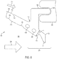
- FIG. 8 illustrates yet another example of the seal engagement region 206.
- the aft seal 204 is a U-shaped groove 804 in a high pressure vane.
- the U-shaped groove 804 is configured to face in the fore direction and to receive a "porpoise nose" portion 802 or an aft-facing projection of the combustion liner 202.
- the seal engagement region 206 includes an area radially inward from the "porpoise nose" portion 802, which includes, for example, the outlets 406 of the cooling passages 402.
- the distance from the outlet 406 of one of the cooling passages 402 to the end surface 432 of the combustion liner 202 is designated “d” in FIG. 2 .
- the thickness of the combustion liner 202 is designed “t” in FIG. 2 .
- the ratio of d to t may be in a range of 1 ⁇ 2 to 1 ⁇ 4.
- the ratio of d to t may be outside of the range of 1 ⁇ 2 to 1 ⁇ 4.
- the outlet 406s of the cooling passages 402 may be configured to direct a stream of the cooling fluid 214 beyond the end surface 432 of the combustion liner 202.
- each of the outlets 406 may be greater than or equal to a cross-sectional area of a corresponding one of the inlets 404.
- a ratio of the cross-sectional area the outlet 406 to the cross-sectional area of the inlet 404 may be in a range from 1.8 to 2.2.
- the ratio of the cross-sectional area the outlet 406 to the cross-sectional area of the inlet 404 may be outside of the range from 1.8 to 2.2.
- the cross-sectional area of one or more of the inlets 404 may be at least twice the cross-sectional area of one or more of the trim hole inlets 710. Alternatively or in addition, the ratio between the cross-sectional area of the inlet 404 and the cross-sectional area of the trim hole inlets 710 may be less than two.
- the combustion liner 202 may be a double wall component comprising an outer wall that includes the hot side 210 and an inner wall that includes the cold side 212.
- One or more of the pedestals 420 may be coupled at a first end of the pedestal(s) to the outer wall and a second end of the pedestal(s) to the inner wall.
- the cooling fluid 214 may be received at the inlet 404 on the outer surface 212 of the combustion liner 202 for a combustor of the gas turbine engine 100.
- the cooling fluid 214 may be directed through one or more of the cooling passageways 402 located in the combustion liner 202 radially inward of the aft seal 204 that overlaps the combustion liner 202.
- the cooling fluid 214 may be directed from the one or more of the cooling passageways 402 through one or more of the outlets 406 into the primary gas flow path 208, wherein the one or more of the outlets 406 is located radially inward of the aft seal 204.
- the operations may be carried out in the order listed in this paragraph. Alternatively, the operations may be carried out in a different order.
- the phrases "at least one of ⁇ A>, ⁇ B>, ... and ⁇ N>” or “at least one of ⁇ A>, ⁇ B>, ... ⁇ N>, or combinations thereof or " ⁇ A>, ⁇ B>, ... and/or ⁇ N>” are defined by the Applicant in the broadest sense, superseding any other implied definitions hereinbefore or hereinafter unless expressly asserted by the Applicant to the contrary, to mean one or more elements selected from the group comprising A, B, ... and N. In other words, the phrases mean any combination of one or more of the elements A, B, ...
- the subject-matter of the disclosure may also relate, among others, to the following aspects:
Landscapes
- Engineering & Computer Science (AREA)
- Mechanical Engineering (AREA)
- General Engineering & Computer Science (AREA)
- Chemical & Material Sciences (AREA)
- Combustion & Propulsion (AREA)
- Turbine Rotor Nozzle Sealing (AREA)
Abstract
Description
- This disclosure relates to gas turbine engines and, in particular, to a combustion liner for a gas turbine engine, and a system for combustor cooling and/or trim air profile control.
- Gas turbine engines may include a compressor, a combustor, and a turbine. Typically, the compressor is an air compressor rotating on a shaft of the engine to provide air for the combustion cycle. Parts of the turbine may be subject to relatively high temperatures, such as from exhaust gas discharged by the combustor. In some gas turbines, a cooling fluid, such as cooling air, may be used to cool parts of the turbine. Such cooling fluid may be supplied from the compressor, from another part of the gas turbine engine, or from an air supply external to the gas turbine engine.
- The present disclosure provides a combustion liner for a gas turbine engine, a system, and a method, as set out in the appended claims.
- In a first aspect the present disclosure provides a combustion liner for a gas turbine engine, the combustion liner comprising: a seal engagement region configured to couple with an aft seal; a plurality of cooling passages in the seal engagement region; a plurality of inlets to the cooling passages, the inlets located on an outer surface of the combustion liner; and a plurality of outlets for the cooling passages, the outlets located on an inner surface of the combustion liner in the seal engagement region, wherein the inner surface is configured to face radially inward toward a combustion chamber, and the outer surface is configured to face radially outward relative to the combustion chamber.
- The inlets may be located on a curved section of the outer surface of the combustion liner, where the curved section may curve radially outward from the inner surface of the combustion liner.
- The combustion liner may further comprise a plurality of trim hole inlets on the outer surface of the combustion liner, wherein the inlets to the cooling passageways may have a larger cross-sectional area than the trim hole inlets.
- Each of the inlets may open into a corresponding cylindrical cooling passage, the corresponding cylindrical cooling passage may be disposed within the combustion liner at an angle relative to the inner surface, the corresponding cylindrical cooling passage may expand into a supply passageway that has a substantially rectangular cross-section and may extend substantially parallel to the inner surface of the combustion liner in an aft direction, and the supply passageway may be included within the seal engagement region.
- The combustion liner may further comprise at least one pedestal disposed in at least one of the cooling passages.
- The combustion liner may be a double wall component comprising an outer wall that includes the outer surface and an inner wall that includes the inner surface, the pedestal may be coupled at a first end to the outer wall and a second end to the inner wall.
- A distance from a corresponding one of the outlets to an aft end surface of the combustion liner divided by a thickness of the combustion liner at the corresponding one of the outlets may be in a range of ½ to ¼, and optionally the combustion liner may be at least an aft end of combustor tile.
- In a second aspect the present disclosure provides a system comprising: a combustion liner configured to be included in an aft end of a combustor for a gas turbine engine; and an aft seal movably engaged with the combustion liner in a seal engagement region, wherein the combustion liner comprises an inlet formed in an outer surface of the combustion liner to receive a cooling fluid, and an outlet in fluid communication with the inlet via a passageway formed within the combustion liner, the outlet disposed in an inner surface of the combustion liner in the seal engagement region.
- The combustion liner of the system may be a combustion liner of the first aspect.
- The outlet of the system may be configured (a) to direct a stream of the cooling fluid into an exhaust gas stream in a primary gas flow path of the gas turbine engine, or (b) to direct a stream of the cooling fluid beyond an aft end of the combustion liner.
- In the system the combustion liner may comprise trim holes and the inlet that is in fluid communication with the outlet may be further aft than the trim holes.
- The combustion liner and a portion of the aft seal overlap in the seal engagement region and the outlet may be radially inward of the aft seal.
- The inlet may be outside of the seal engagement region, and the passageway in the seal engagement region may include a supply passageway that is substantially parallel to the inner surface of the combustion liner.
- At least a portion of the aft seal may be nested inside of the combustion liner and the outlet may be radially inward from the portion of the aft seal nested inside the combustion liner.
- The inlet may comprise a plurality of inlets in fluid communication with the passageway, and the outlet may comprise a series of slots in fluid communication with the passageway.
- In a third aspect the present disclosure provides a method comprising: receiving a cooling fluid at an inlet on an outer surface of a combustion liner for a combustor of a gas turbine engine; directing the cooling fluid through a passageway located in the combustion liner radially inward of an aft seal that overlaps the combustion liner; and directing the cooling fluid from the passageway through an outlet of the combustion liner into a primary gas flow path, wherein the outlet is located radially inward of the aft seal.
- The combustion liner in the method may be a combustion liner of the first aspect.
- In the method, receiving the cooling fluid may comprise receiving the cooling fluid at a curved section of the outer surface, wherein the curved section may be curved further away from an inner surface of the combustion liner in an aft direction than in a fore direction.
- Directing the cooling fluid into the primary gas flow path may include injecting the cooling fluid beyond an aft end of the combustion liner.
- The method may further comprise routing the cooling fluid in the passageway around a pedestal included in the passageway.
- The skilled person will appreciate that except where mutually exclusive, a feature or parameter described in relation to any one of the above aspects may be applied to any other aspect. Furthermore, except where mutually exclusive, any feature or parameter described herein may be applied to any aspect and/or combined with any other feature or parameter described herein.
- The embodiments may be better understood with reference to the following drawings and description. The components in the figures are not necessarily to scale. Moreover, in the figures, like-referenced numerals designate corresponding parts throughout the different views.
-
FIG. 1 is a cross-sectional view of a gas turbine engine; -
FIG. 2 is a cross-sectional view of an aft end of a combustion liner and an aft seal movably engaged with the combustion liner in a seal engagement region; -
FIG. 3 is a perspective view of the aft end of the combustion liner; -
FIG. 4 is a perspective view of cooling passages, which are inside of the aft end of the combustion liner; -
FIG. 5 is a second cross-sectional view of the aft end of the combustion liner; -
FIG. 6 is a perspective view of the aft end of the combustion liner showing the hot side of the combustion liner; -
FIG. 7 is a perspective view of the aft end of the combustion liner showing the cold side of the combustion liner; and -
FIG. 8 is a cross-section view of a second example of a seal engagement region. - By way of an introductory example, a combustion liner for a gas turbine engine may be provided. The combustion liner may include: a seal engagement region configured to couple with an aft seal; a plurality of cooling passages in the seal engagement region; a plurality of inlets to the cooling passages, the inlets located on an outer surface of the combustion liner; and a plurality of outlets for the cooling passages, the outlets located on an inner surface of the combustion liner in the seal engagement region, wherein the inner surface is configured to face radially inward toward a combustion chamber, and the outer surface is configured to face radially outward relative to the combustion chamber
-
FIG. 1 is a cross-sectional view of agas turbine engine 100. In some examples, thegas turbine engine 100 may supply power to and/or provide propulsion of an aircraft. Examples of the aircraft may include a helicopter, an airplane, an unmanned space vehicle, a fixed wing vehicle, a variable wing vehicle, a rotary wing vehicle, an unmanned combat aerial vehicle, a tailless aircraft, a hover craft, and any other airborne and/or extraterrestrial (spacecraft) vehicle. Alternatively or in addition, thegas turbine engine 100 may be utilized in a configuration unrelated to an aircraft such as, for example, an industrial application, an energy application, a power plant, a pumping set, a marine application (for example, for naval propulsion), a weapon system, a security system, and a perimeter defense or security system. - The
gas turbine engine 100 may take a variety of forms in various embodiments. Though depicted as an axial flow engine inFIG. 1 , in some forms thegas turbine engine 100 may have multiple spools and/or may be a centrifugal or mixed centrifugal/axial flow engine. In some forms, thegas turbine engine 100 may be a turboprop, a turbofan, or a turboshaft engine. Furthermore, thegas turbine engine 100 may be an adaptive cycle and/or variable cycle engine. Other variations are also contemplated. - The
gas turbine engine 100 may include anintake section 120, acompressor section 160, acombustion section 130, aturbine section 110, and anexhaust section 150. During operation of thegas turbine engine 100, fluid received from theintake section 120, such as air, travels along the direction D1 and may be compressed within thecompressor section 160. The compressed fluid may then be mixed with fuel and the mixture may be burned in thecombustion section 130. Thecombustion section 130 may include any suitable fuel injection and combustion mechanisms. The hot, high pressure fluid may then pass through theturbine section 110 to extract energy from the fluid and cause a turbine shaft of aturbine 114 in theturbine section 110 to rotate, which in turn drives thecompressor section 160. Discharge fluid may exit theexhaust section 150. - As noted above, the hot, high pressure fluid passes through the
turbine section 110 during operation of thegas turbine engine 100. As the fluid flows through theturbine section 110, the fluid passes betweenadjacent blades 112 of theturbine 114 causing theturbine 114 to rotate. The rotatingturbine 114 may turn ashaft 140 in a rotational direction D2, for example. Theblades 112 may rotate around an axis of rotation, which may correspond to a centerline X of theturbine 114 in some examples. - A system for combustor cooling and trim air profile control may be located in an
area 180 of thegas turbine engine 100 where the hot, high pressure fluid passes from acombustion chamber 104 of thecombustion section 130 into theturbine section 110. An example of thesystem 102 for combustor cooling and trim air profile control is illustrated inFIGS. 2-7 . -
FIG. 2 is a cross-sectional view of an aft end of acombustion liner 202 and anaft seal 204 movably engaged with thecombustion liner 202 in aseal engagement region 206. Theseal engagement region 206 may include a portion of thecombustion liner 202 configured to engage or otherwise couple to theaft seal 204. Thecombustion liner 202 is a component that may contain the combustion process. Alternatively or in addition, thecombustion liner 202 may introduce one or more airflows such as cooling air. Thecombustion liner 202 may define at least part of thecombustion chamber 104. Thecombustion liner 202 may be made of any material suitable to withstand the relatively high temperatures resulting from combustion of fuel, such as a metal alloy, a superalloy, and/or a ceramic matrix composite. - The
aft seal 204 may couple to a high-pressure vane (not shown) located in theturbine section 110. Ahot side 210 of thecombustion liner 202 is called "hot" because thehot side 210 is designed to face thecombustion chamber 104 through which relatively hot gasses flow along a primarygas flow path 208. Conversely, acold side 212 of thecombustion liner 202 is called "cold" because thecold side 212 is designed to havecooling fluid 214, such as cooling air, flow along thecold side 212. Accordingly, the adjectives "hot" and "cold" used in connection with the terms "hot side" and "cold side", respectively, refer to relative position, not to temperatures. For example, thehot side 210 may be referred to as an inner surface of thecombustion liner 202 because thehot side 210 is configured to face radially inward toward thecombustion chamber 104. Similarly, thecold side 212 may be referred to as an outer surface of thecombustion liner 202 because thecold side 212 is configured to face radially outward relative to thecombustion chamber 104. - The
aft seal 204 is component configured to limit or prevent the cold air from escaping between thecombustion liner 202 and the high-pressure vane located in theturbine section 110. Theseal engagement region 206 may be a portion of thecombustion liner 202 configured to engage or otherwise couple to theaft seal 204. -
FIG. 3 is a perspective view of the aft end of thecombustion liner 202. Theaft seal 204 is not shown inFIG. 2 so that features of thecombustion liner 202 are not obscured by theaft seal 204. The cross-sectional view of thecombustion liner 202 shown inFIG. 2 is the cross-section indicated by arrows A and B inFIG. 3 . -
FIG. 4 is a perspective view ofcooling passages 402, which are inside of the aft end of thecombustion liner 202. Thecooling passages 402 includeinlets 404 andoutlets 406. Thecooling passages 402 are largely hidden from view inFIGS. 2-3 . However, one of theoutlets 406 is visible inFIGS. 2-3 . In addition,portions 408 of the coolingpassageways 402 that intersect the cross-section indicated by arrows A and B are shown inFIGS. 2-3 . -
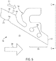
FIG. 5 is a second cross-sectional view of the aft end of thecombustion liner 202. The cross-sectional view of thecombustion liner 202 shown inFIG. 5 is the cross-section indicated by arrows C and D inFIG. 4 . The cross-section indicated by arrows C and D intersects one of theinlets 404 andportions 508 of thecooling passageways 402. However, the cross-section intersects an area of thecombustion liner 202 between theoutlets 406, so nooutlets 406 are visible inFIG. 5 . -
FIG. 6 is a perspective view of the aft end of thecombustion liner 202 showing thehot side 210 of thecombustion liner 202. The portion of thecombustion liner 202 shown inFIG. 6 is a corner of a tile. Again, thecooling passages 402 are largely hidden from view. However, theoutlets 406, which are located on thehot side 210 of thecombustion liner 202, are clearly visible. Only a subset of theoutlets 406 shown inFIG. 6 are indicated by lead lines. Also visible inFIG. 6 are openings 608 into the coolingpassageways 402, which are on anedge side 602 of the tile. Theedge side 602 of the tile is configured to abut an adjacent tile that has corresponding openings, which align with the openings 608 on theedge side 602 of the tile shown inFIG. 6 . Multiple tiles like the one shown inFIG. 6 may be arranged to form a complete annular combustion liner. -
FIG. 7 is a perspective view of the aft end of thecombustion liner 202 showing thecold side 212 of thecombustion liner 202. The portion of thecombustion liner 202 shown inFIG. 7 is a complete aft end of a tile. InFIG. 7 , thecooling passages 402 are hidden from view except for theinlets 404. Only a subset of theinlets 404 shown inFIG. 7 are indicated by lead lines. In the illustrated example, theinlets 404 are located on acurved section 702 on thecold side 212 of thecombustion liner 202. - During operation of the
system 102 for combustor cooling and trim air profile control, cooling fluid 214 flows along thecold side 212 of thecombustion liner 202 in an aft direction. The cooling fluid 214 approaches thecurved section 702 of the combustion liner 20 and then enters theinlets 404 located on thecurved section 702. The cooling fluid 214 flows through thecooling passages 402 in thecombustion liner 202. As the cooling fluid 214 flows through thecooling passages 402, the coolingfluid 214 cools thecombustion liner 202 in theseal engagement region 206. The cooling fluid 214 exits thecombustion liner 202 through theoutlets 406. The cooling fluid 214 that exits through theoutlets 406 cools the gases in the primarygas flow path 208. As a result, the cooling fluid 214 that exits through theoutlets 406 acts as trim air that affects the combustor exit temperature profile. - Design requirements may stipulate the shape of the temperature profile of gasses exiting the combustor in the primary
gas flow path 208. For example, lowering the temperature of the gases in radially outer regions of the primarygas flow path 208 in theturbine section 110 may help prolong the life of theblades 112 and/or vanes in theturbine section 110. - The speed, quantity, and/or angle of the cooling fluid 214 that exits the
outlets 406, and/or the size and shape of theoutlets 406 may be selected to control the trim air and, consequently, the shape of the temperature profile of gasses exiting the combustor and entering theturbine section 110. For example, trim air jet penetration may be increased by decreasing a ratio of the area of theoutlets 406 to the area of theinlets 404. Specifically, decreasing the ratio of the area of theoutlets 406 to the area of theinlets 404 may increase the momentum of the coolingfluid 214 exiting theoutlets 406, thus increasing trim air jet penetration. Conversely, increasing the ratio of the area of theoutlets 406 to the area of theinlets 404 may decrease trim jet penetration. Alternatively or in addition, trim air jet penetration may be increased by steepening the angle of thecooling passages 402 at theoutlets 406. Steepening the angle of thecooling passages 402 at theoutlets 406 means orienting thecooling passages 402 to eject the coolingfluid 214 closer to a radially inward direction, which is perpendicular to the primarygas flow path 208. - Trim holes, which have
trim hole inlets 710 on thecold side 212 of thecombustion liner 202 andtrim hole outlets 610 on thehot side 210 of thecombustion liner 202, may also control the trim air and, consequently, the shape of the temperature profile of gasses exiting the combustor and entering theturbine section 110. Not all of thetrim hole inlets 710 and thetrim hole outlets 610 are indicated with lead lines inFIGS. 6 and7 . Thetrim hole outlets 610 may be larger than thetrim hole inlets 710 in some examples, such as the example illustrated inFIGS 2-7 . The trim holes may be angled with respect to thecold side 212 and/or thehot side 210. The trim holes may be machined, for example by drilling, into thecombustion liner 202. However, unlike thecooling passages 402 described herein, the trim holes cannot extend the trim air cooling effect to the end of thecombustion liner 202 because structures in theseal engagement region 206, such as theaft seal 204 and the portion of thecombustion liner 202 that engages theaft seal 204, may get in the way. For example, even drilling the trim holes at an angle may be insufficient to reach into theseal engagement region 206 and/or to position thetrim hole outlets 610 as far aft as theoutlets 406 of thecooling passages 402 discussed earlier above. Furthermore, thecooling passages 402 may use less of the cooling fluid 214 with thecooling passages 402 to obtain a target temperature profile than without thecooling passages 402. Using less cooling fluid for cooling allows more to be used for combustion, which may be more and more important for high performance, high thrust engines. - Referring back to
FIG. 4 , thecooling passages 402, which pass through theseal engagement region 206 of thecombustion liner 202, may have a more complex shape than the trim holes. In the example shown inFIG. 4 , each of theinlets 404 opens into a correspondingcylindrical cooling passage 410, which is angled down into thecombustion liner 202 and toward theseal engagement region 206. The correspondingcylindrical cooling passage 410 expands into asupply passageway 412 that has a substantially rectangular cross-section and extends substantially parallel to thehot side 210 of thecombustion liner 202 in anaft direction 414.Adjacent supply passageways 412 are connected viaoval passageways 416 that extend in acircumferential direction 418, which is substantially perpendicular to the aft direction 414 (not all of theoval passageways 416 are indicated by lead lines inFIG. 4 ). An array ofpedestals 420 are located in thesupply passageways 412 and between adjacent supply passageways 412 (not all of thepedestals 420 are indicated by lead lines inFIG. 4 ). Thepedestals 420 that are located between any twoadjacent supply passageways 412 may define, at least in part, theoval passageways 416 that connect the twoadjacent supply passageways 412. Thepedestals 420 help maintain the structural integrity of thecombustion liner 202 and also aid in increasing the cooling effect of the cooling fluid 214 that flows through thecooling passageways 412. Thesupply passageways 412 lead intoexit passageways 422, which in turn lead to theoutlets 406. Accordingly, the exit passageways 422 are angled toward thehot side 210 of thecombustion liner 202 in theaft direction 414. Each of theexit passageways 422 and corresponding one of theoutlets 406 are located between two corresponding adjacent supply passageways 412 (and, therefore, between two corresponding adjacent inlets 404). In other words, theinlets 404 and theoutlets 406 are offset from one another. - The exit passageways 422 and/or the corresponding
outlets 406 may be in the form of a series of slots. Alternatively, theexit passageways 422 and/or theoutlets 406 may be cylindrical or any other suitable shape. - The
system 102 for combustor cooling and trim air profile control may be implemented in many different ways. For example, thesystem 102 may include only the part of the aft end of thecombustion liner 202 that includes the coolingpassageways 402 in theseal engagement region 206. Alternatively, thesystem 102 may include only a combustion liner tile that includes the coolingpassageways 402 in theseal engagement region 206. Alternatively or in addition, thesystem 102 may include thecombustion liner 202, which includes a complete annular combustion liner or a subset thereof, wherein the coolingpassageways 402 are in theseal engagement region 206 of thecombustion liner 202. In some examples, thesystem 102 may include one or more components in addition tocombustion liner 202, such as theaft seal 204. - In some examples, the
combustion liner 202 is part of an annular combustion chamber. A combustion liner for an annular combustion chamber includes an outer combustion liner and an inner combustion liner. Thecombustion liner 202 may be an outer combustion liner if thehot side 210 of thecombustion liner 202 faces radially inward toward the centerline X of thegas turbine engine 100, and if thecold side 212 of thecombustion liner 202 faces radially outward from the centerline X. Alternatively, thecombustion liner 202 may be an inner combustion liner if thehot side 210 of thecombustion liner 202 faces radially outward away from the centerline X of thegas turbine engine 100, and if thecold side 212 of thecombustion liner 202 faces radially inward toward the centerline X. The aft end of the inner combustion liner may have, in some examples, the same structure as the outer combustion liner but inverted. Alternatively, the structure of the aft end of the inner combustion liner may be different than the outer combustion liner. - In some examples, the
combustion liner 202 is part of a can-annular combustor. A can-annular combustor may comprise an annular outer shell and a number of individual cylindrical liners mounted about the centerline X of thegas turbine engine 100. Thecombustion liner 202, such as the one illustrated inFIGS. 2-7 , may be any of the cylindrical liners for a can-annular combustor. - In the example illustrated in
FIGS. 2-7 , theinlets 404 are located in thecurved section 702 on thecold side 212 of thecombustion liner 202. Moving in theaft direction 414 along thecurved section 702, thecold side 212 on thecurved section 702 curves away from thehot side 210. Thecurved section 702 may aid in directing the coolingfluid 214 into theinlets 404. Alternatively, theinlets 404 may not be located on acurved section 702 on thecold side 212. More generally, theinlets 404 to the coolingpassageways 402 are formed in thecold side 212 of thecombustion liner 202 and are configured to receive the coolingfluid 214. - The
inlets 404 and/or theoutlets 406 may be arranged uniformly, irregularly, or a combination thereof, in thecircumferential direction 418. Theinlets 404 and/or theoutlets 406 may be oriented in any direction relative to thecold side 212 and thehot side 210, respectively. - The cooling
passageways 402 may have any suitable structure and, therefore, be different than illustrated inFIGS. 2-7 . For example, corresponding pairs of theinlets 404 and theoutlets 406 may be aligned along an axial axis instead of being offset from each other as shown inFIG. 4 . As another example, the coolingpassageways 402 may not include theoval passageways 416 that extend in thecircumferential direction 418 and connect theadjacent supply passageways 412. Alternatively or in addition, each of thesupply passageways 412 may be a discrete passageway, unconnected to any of theother supply passageways 412. Alternatively or in addition, thecombustion liner 202 may not include the openings 608 on theedge side 602 of the tile to thecooling passageways 402. Alternatively or in addition, thecombustion liner 202 may not include thepedestals 420. For example, thesupply passageways 412 may connect a corresponding one of theinlets 404 with a corresponding one of theoutlets 406 without including any pedestal on the path from theinlet 404 to theoutlet 406. Alternatively or in addition, the shapes and/or dimensions of thecooling passages 402 may vary from example to example. - As noted above, the
seal engagement region 206 may be a portion of thecombustion liner 202 that is configured to engage or otherwise couple to theaft seal 204. Referring toFIG. 3 , the portion of thecombustion liner 202 that is included in theseal engagement region 206 may be any portion bounded by afirst plane 426 and asecond plane 428, where thefirst plane 426 is parallel to thesecond plane 428, where thefirst plane 426 and thesecond plane 428 are perpendicular to an axis that extends in theaft direction 414, where thefirst plane 426 intersects apoint 430 at which thecombustion liner 202 is configured to contact or engage theaft seal 204, and where thesecond plane 428 intersects anend surface 432 of thecombustion liner 202 configured to face theaft direction 414. The first andsecond planes 426 may be parallel to anaxis 424 that extends radially from a longitudinal axis of thecombustion liner 202. Theaxis 424 that extends radially from the longitudinal axis is perpendicular to both the axis that extends in theaft direction 414 and an axis that extends in thecircumferential direction 418. Alternatively or in addition, theseal engagement region 206 may be the portion of thecombustion liner 202 between theend surface 432 and a point on thehot side 210 that cannot be reached by drilling a trim hole from thecold side 212 further to the fore (opposite of the aft direction 414) than thecurved section 702. Alternatively or in addition, theseal engagement region 206 may be the portion of thecombustion liner 202 that is radially inward from a portion of thecombustion liner 202 that receives and/or abuts theaft seal 204. Thecombustion liner 202 and theaft seal 204 may overlap in theseal engagement region 206 such that one or more of theoutlets 406 are radially inward of at least part of theaft seal 204. - The
seal engagement region 206 may have an entirely different structure than the example illustrated inFIGS. 2-7 . The structure of theseal engagement region 206 may vary from example to example because the means for connecting - and/or sealing a gap between - thecombustion liner 202 and the high pressure vanes varies widely from design to design. In the example illustrated inFIGS. 2-7 , theaft seal 204 is enveloped at least partly by an aft-facing U-shaped portion of thecombustion liner 202 within theseal engagement region 206. In other examples, theaft seal 204 may be enveloped at least partly by a differently shaped and/or oriented portion of thecombustion liner 202 within theseal engagement region 206.FIG. 8 illustrates yet another example of theseal engagement region 206. In the example shown inFIG. 8 , theaft seal 204 is aU-shaped groove 804 in a high pressure vane. TheU-shaped groove 804 is configured to face in the fore direction and to receive a "porpoise nose"portion 802 or an aft-facing projection of thecombustion liner 202. Theseal engagement region 206 includes an area radially inward from the "porpoise nose"portion 802, which includes, for example, theoutlets 406 of thecooling passages 402. - The distance from the
outlet 406 of one of thecooling passages 402 to theend surface 432 of thecombustion liner 202 is designated "d" inFIG. 2 . The thickness of thecombustion liner 202 is designed "t" inFIG. 2 . In some examples, the ratio of d to t may be in a range of ½ to ¼. Alternatively, the ratio of d to t may be outside of the range of ½ to ¼. The outlet 406s of thecooling passages 402 may be configured to direct a stream of the coolingfluid 214 beyond theend surface 432 of thecombustion liner 202. - The cross-sectional area of each of the
outlets 406 may be greater than or equal to a cross-sectional area of a corresponding one of theinlets 404. In some examples, a ratio of the cross-sectional area theoutlet 406 to the cross-sectional area of theinlet 404 may be in a range from 1.8 to 2.2. Alternatively, the ratio of the cross-sectional area theoutlet 406 to the cross-sectional area of theinlet 404 may be outside of the range from 1.8 to 2.2. - The cross-sectional area of one or more of the
inlets 404 may be at least twice the cross-sectional area of one or more of thetrim hole inlets 710. Alternatively or in addition, the ratio between the cross-sectional area of theinlet 404 and the cross-sectional area of thetrim hole inlets 710 may be less than two. - In some examples, the
combustion liner 202 may be a double wall component comprising an outer wall that includes thehot side 210 and an inner wall that includes thecold side 212. One or more of thepedestals 420 may be coupled at a first end of the pedestal(s) to the outer wall and a second end of the pedestal(s) to the inner wall. - During operation of some examples of the
system 102, the coolingfluid 214 may be received at theinlet 404 on theouter surface 212 of thecombustion liner 202 for a combustor of thegas turbine engine 100. The coolingfluid 214 may be directed through one or more of the coolingpassageways 402 located in thecombustion liner 202 radially inward of theaft seal 204 that overlaps thecombustion liner 202. The coolingfluid 214 may be directed from the one or more of the coolingpassageways 402 through one or more of theoutlets 406 into the primarygas flow path 208, wherein the one or more of theoutlets 406 is located radially inward of theaft seal 204. The operations may be carried out in the order listed in this paragraph. Alternatively, the operations may be carried out in a different order. - To clarify the use of and to hereby provide notice to the public, the phrases "at least one of <A>, <B>, ... and <N>" or "at least one of <A>, <B>, ... <N>, or combinations thereof or "<A>, <B>, ... and/or <N>" are defined by the Applicant in the broadest sense, superseding any other implied definitions hereinbefore or hereinafter unless expressly asserted by the Applicant to the contrary, to mean one or more elements selected from the group comprising A, B, ... and N. In other words, the phrases mean any combination of one or more of the elements A, B, ... or N including any one element alone or the one element in combination with one or more of the other elements which may also include, in combination, additional elements not listed. Unless otherwise indicated or the context suggests otherwise, as used herein, "a" or "an" means "at least one" or "one or more."
- While various embodiments have been described, it will be apparent to those of ordinary skill in the art that many more embodiments and implementations are possible. Accordingly, the embodiments described herein are examples, not the only possible embodiments and implementations.
- The subject-matter of the disclosure may also relate, among others, to the following aspects:
- A first aspect relates to a system comprising: a combustion liner configured to be included in an aft end of a combustor for a gas turbine engine; and an aft seal movably engaged with the combustion liner in a seal engagement region, wherein the combustion liner comprises an inlet formed in an outer surface of the combustion liner to receive a cooling fluid, and an outlet in fluid communication with the inlet via a passageway formed within the combustion liner, the outlet disposed in an inner surface of the combustion liner in the seal engagement region.
- A second aspect relates to the system of aspect 1, wherein the outlet is configured to direct a stream of the cooling fluid into an exhaust gas stream in a primary gas flow path of the gas turbine engine.
- A third aspect relates to the system of any of aspects 1 to 2, wherein the outlet is configured to direct a stream of the cooling fluid beyond an aft end of the combustion liner.
- A fourth aspect relates to the system of any of aspects 1 to 3, wherein the combustion liner comprises trim holes and the inlet that is in fluid communication with the outlet is further aft than the trim holes.
- A fifth aspect relates to the system of any of aspects 1 to 4, wherein the combustion liner and a portion of the aft seal overlap in the seal engagement region and the outlet is radially inward of the aft seal.
- A fourth aspect relates to the system of any of aspects 1 to 5, wherein the inlet is outside of the seal engagement region, and the passageway in the seal engagement region includes a supply passageway that is substantially parallel to the inner surface of the combustion liner.
- A seventh aspect relates to the system of any of aspects 1 to 6, wherein at least a portion of the aft seal is nested inside of the combustion liner and the outlet is radially inward from the portion of the aft seal nested inside the combustion liner.
- An eighth aspect relates to the system of any of aspects 1 to 7, wherein the inlet comprises a plurality of inlets in fluid communication with the passageway, and the outlet comprises a series of slots in fluid communication with the passageway.
- A ninth aspect relates to a combustion liner for a gas turbine engine, the combustion liner comprising: a seal engagement region configured to couple with an aft seal; a plurality of cooling passages in the seal engagement region; a plurality of inlets to the cooling passages, the inlets located on an outer surface of the combustion liner; and a plurality of outlets for the cooling passages, the outlets located on an inner surface of the combustion liner in the seal engagement region, wherein the inner surface is configured to face radially inward toward a combustion chamber, and the outer surface is configured to face radially outward relative to the combustion chamber.
- A tenth aspect relates to the combustion liner of aspect 9, wherein the inlets are located on a curved section of the outer surface of the combustion liner, where the curved section curves radially outward from the inner surface of the combustion liner.
- An eleventh aspect relates to the combustion liner of any of aspects 9 to 10 further comprising a plurality of trim hole inlets on the outer surface of the combustion liner, wherein the inlets to the cooling passageways have a larger cross-sectional area than the trim hole inlets.
- A twelfth aspect relates to the combustion liner of any of aspects 9 to 11, wherein each of the inlets opens into a corresponding cylindrical cooling passage, the corresponding cylindrical cooling passage is disposed within the combustion liner at an angle relative to the inner surface, the corresponding cylindrical cooling passage expands into a supply passageway that has a substantially rectangular cross-section and extends substantially parallel to the inner surface of the combustion liner in an aft direction, and the supply passageway is included within the seal engagement region.
- A thirteenth aspect relates to the combustion liner of any of aspects 9 to 12 further comprising at least one pedestal disposed in at least one of the cooling passages.
- A fourteenth aspect relates to the combustion liner of aspect 13, wherein the combustion liner is a double wall component comprising an outer wall that includes the outer surface and an inner wall that includes the inner surface, the pedestal coupled at a first end to the outer wall and a second end to the inner wall.
- A fifteenth aspect relates to the combustion liner of any of aspects 9 to 14, wherein a distance from a corresponding one the outlets to an aft end surface of the combustion liner divided by a thickness of the combustion liner at the corresponding one of the outlets is in a range of ½ to ¼.
- A sixteenth aspect relates to the combustion liner of any of aspects 9 to 15, wherein the combustion liner is at least an aft end of combustor tile.
- A seventeenth aspect relates to a method comprising: receiving a cooling fluid at an inlet on an outer surface of a combustion liner for a combustor of a gas turbine engine; directing the cooling fluid through a passageway located in the combustion liner radially inward of an aft seal that overlaps the combustion liner; and directing the cooling fluid from the passageway through an outlet of the combustion liner into a primary gas flow path, wherein the outlet is located radially inward of the aft seal.
- A eighteenth aspect relates to the method of aspect 17, wherein receiving the cooling fluid comprises receiving the cooling fluid at a curved section of the outer surface, wherein the curved section is curved further away from an inner surface of the combustion liner in an aft direction than in a fore direction.
- A nineteenth aspect relates to the method of any of aspects 17 to 18, wherein directing the cooling fluid into the primary gas flow path includes injecting the cooling fluid beyond an aft end of the combustion liner.
- A twentieth aspect relates to the method of any of aspects 17 to 19, further comprising routing the cooling fluid in the passageway around a pedestal included in the passageway.
Claims (15)
- A combustion liner (202) for a gas turbine engine (100), the combustion liner comprising:a seal engagement region (206) configured to couple with an aft seal (204);a plurality of cooling passages (402) in the seal engagement region;a plurality of inlets (404) to the cooling passages, the inlets located on an outer surface (212) of the combustion liner; anda plurality of outlets (406) for the cooling passages, the outlets located on an inner surface (210) of the combustion liner in the seal engagement region, wherein the inner surface is configured to face radially inward toward a combustion chamber (104), and the outer surface (212) is configured to face radially outward relative to the combustion chamber.
- The combustion liner of claim 1, wherein the inlets (404) are located on a curved section (702) of the outer surface (212) of the combustion liner, where the curved section curves radially outward from the inner surface (210) of the combustion liner.
- The combustion liner of claim 2 or 3, further comprising a plurality of trim hole inlets (710) on the outer surface (212) of the combustion liner, wherein the inlets (404) to the cooling passages (402) have a larger cross-sectional area than the trim hole inlets.
- The combustion liner of any preceding claim, wherein each of the inlets (404) opens into a corresponding cylindrical cooling passage (410), the corresponding cylindrical cooling passage is disposed within the combustion liner at an angle relative to the inner surface (210), the corresponding cylindrical cooling passage expands into a supply passageway (412) that has a substantially rectangular cross-section and extends substantially parallel to the inner surface of the combustion liner in an aft direction, and the supply passageway is included within the seal engagement region (206).
- The combustion liner of any preceding claim, further comprising at least one pedestal (420) disposed in at least one of the cooling passages (402).
- The combustion liner of claim 5, wherein the combustion liner is a double wall component comprising an outer wall that includes the outer surface (212) and an inner wall that includes the inner surface (210), the pedestal (420) coupled at a first end to the outer wall and a second end to the inner wall.
- The combustion liner of any preceding claim, wherein a distance from a corresponding one of the outlets (406) to an aft end surface of the combustion liner divided by a thickness of the combustion liner at the corresponding one of the outlets is in a range of ½ to ¼, and optionally the combustion liner is at least an aft end of combustor tile.
- A system comprising:a combustion liner (202) configured to be included in an aft end of a combustor for a gas turbine engine (100); andan aft seal (204) movably engaged with the combustion liner in a seal engagement region (206), wherein the combustion liner comprisesan inlet (404) formed in an outer surface (212) of the combustion liner to receive a cooling fluid, andan outlet (406) in fluid communication with the inlet via a passageway formed within the combustion liner, the outlet disposed in an inner surface of the combustion liner in the seal engagement region.
- The system of claim 8, wherein the outlet (406) is configured (a) to direct a stream of the cooling fluid into an exhaust gas stream in a primary gas flow path (208) of the gas turbine engine, or (b) to direct a stream of the cooling fluid beyond an aft end of the combustion liner.
- The system of claim 8 or 9, wherein (a) the combustion liner comprises trim holes and the inlet (404) that is in fluid communication with the outlet (406) is further aft than the trim holes, and/or (b) the combustion liner and a portion of the aft seal overlap in the seal engagement region (206) and the outlet is radially inward of the aft seal.
- The system of any one of claims 8 to 10, wherein the inlet (404) is outside of the seal engagement region (206), and the passageway in the seal engagement region includes a supply passageway (412) that is substantially parallel to the inner surface of the combustion liner.
- The system of any one of claims 8 to 11, wherein (a) at least a portion of the aft seal (204) is nested inside of the combustion liner and the outlet (406) is radially inward from the portion of the aft seal nested inside the combustion liner, and/or (b) the inlet (404) comprises a plurality of inlets in fluid communication with the passageway, and the outlet comprises a series of slots in fluid communication with the passageway.
- A method comprising:receiving a cooling fluid at an inlet (404) on an outer surface (212) of a combustion liner (200) for a combustor of a gas turbine engine (100);directing the cooling fluid through a passageway located in the combustion liner radially inward of an aft seal (204) that overlaps the combustion liner; anddirecting the cooling fluid from the passageway through an outlet (406) of the combustion liner into a primary gas flow path (208), wherein the outlet is located radially inward of the aft seal.
- The method of claim 13, wherein (a) receiving the cooling fluid comprises receiving the cooling fluid at a curved section of the outer surface (212), wherein the curved section is curved further away from an inner surface (210) of the combustion liner (200) in an aft direction than in a fore direction, and/or (b) directing the cooling fluid into the primary gas flow path (208) includes injecting the cooling fluid beyond an aft end of the combustion liner.
- The method of claim 13 or 14, further comprising routing the cooling fluid in the passageway around a pedestal (420) included in the passageway.
Applications Claiming Priority (1)
| Application Number | Priority Date | Filing Date | Title |
|---|---|---|---|
| US16/029,206 US10801727B2 (en) | 2018-07-06 | 2018-07-06 | System for combustor cooling and trim air profile control |
Publications (2)
| Publication Number | Publication Date |
|---|---|
| EP3591294A1 true EP3591294A1 (en) | 2020-01-08 |
| EP3591294B1 EP3591294B1 (en) | 2022-03-16 |
Family
ID=66685389
Family Applications (1)
| Application Number | Title | Priority Date | Filing Date |
|---|---|---|---|
| EP19177570.9A Active EP3591294B1 (en) | 2018-07-06 | 2019-05-31 | Assembly of a combustion liner and a seal for a gas turbine engine |
Country Status (3)
| Country | Link |
|---|---|
| US (1) | US10801727B2 (en) |
| EP (1) | EP3591294B1 (en) |
| CA (1) | CA3039699A1 (en) |
Families Citing this family (7)
| Publication number | Priority date | Publication date | Assignee | Title |
|---|---|---|---|---|
| US11371701B1 (en) | 2021-02-03 | 2022-06-28 | General Electric Company | Combustor for a gas turbine engine |
| US12146660B2 (en) | 2021-06-07 | 2024-11-19 | General Electric Company | Combustor for a gas turbine engine |
| US11959643B2 (en) | 2021-06-07 | 2024-04-16 | General Electric Company | Combustor for a gas turbine engine |
| US11885495B2 (en) | 2021-06-07 | 2024-01-30 | General Electric Company | Combustor for a gas turbine engine including a liner having a looped feature |
| US12085283B2 (en) | 2021-06-07 | 2024-09-10 | General Electric Company | Combustor for a gas turbine engine |
| US11774098B2 (en) | 2021-06-07 | 2023-10-03 | General Electric Company | Combustor for a gas turbine engine |
| US12152777B2 (en) | 2021-06-07 | 2024-11-26 | General Electric Company | Combustor for a gas turbine engine |
Citations (7)
| Publication number | Priority date | Publication date | Assignee | Title |
|---|---|---|---|---|
| US3965066A (en) * | 1974-03-15 | 1976-06-22 | General Electric Company | Combustor-turbine nozzle interconnection |
| JP2004084601A (en) * | 2002-08-28 | 2004-03-18 | Mitsubishi Heavy Ind Ltd | Combustor and gas turbine |
| JP2004301115A (en) * | 2003-03-14 | 2004-10-28 | Mitsubishi Heavy Ind Ltd | Sealing construction and sealing device of turbine tail pipe |
| US20080202124A1 (en) * | 2007-02-27 | 2008-08-28 | Siemens Power Generation, Inc. | Transition support system for combustion transition ducts for turbine engines |
| US20100034643A1 (en) * | 2008-08-06 | 2010-02-11 | General Electric Company | Transition duct aft end frame cooling and related method |
| US20120034075A1 (en) * | 2010-08-09 | 2012-02-09 | Johan Hsu | Cooling arrangement for a turbine component |
| US20180142563A1 (en) * | 2015-06-03 | 2018-05-24 | Safran Aircraft Engines | Annular wall of a combustion chamber with optimised cooling |
Family Cites Families (12)
| Publication number | Priority date | Publication date | Assignee | Title |
|---|---|---|---|---|
| US3741678A (en) | 1971-04-28 | 1973-06-26 | Westinghouse Electric Corp | Cooling air profiling structures for a gas turbine |
| US5220795A (en) | 1991-04-16 | 1993-06-22 | General Electric Company | Method and apparatus for injecting dilution air |
| US5289686A (en) | 1992-11-12 | 1994-03-01 | General Motors Corporation | Low nox gas turbine combustor liner with elliptical apertures for air swirling |
| US6554562B2 (en) | 2001-06-15 | 2003-04-29 | Honeywell International, Inc. | Combustor hot streak alignment for gas turbine engine |
| US6701714B2 (en) | 2001-12-05 | 2004-03-09 | United Technologies Corporation | Gas turbine combustor |
| US20060130486A1 (en) | 2004-12-17 | 2006-06-22 | Danis Allen M | Method and apparatus for assembling gas turbine engine combustors |
| GB2461542B (en) | 2008-07-03 | 2010-10-13 | Rolls Royce Plc | Combustion Arrangement with Dilution and Trim Ports |
| US9134208B2 (en) | 2012-07-31 | 2015-09-15 | Smiths Detection Montreal Inc. | Solid phase micro extraction (SPME) vacuum inlet |
| US10260748B2 (en) | 2012-12-21 | 2019-04-16 | United Technologies Corporation | Gas turbine engine combustor with tailored temperature profile |
| GB201315871D0 (en) * | 2013-09-06 | 2013-10-23 | Rolls Royce Plc | A combustion chamber arrangement |
| GB201417429D0 (en) * | 2014-10-02 | 2014-11-19 | Rolls Royce Plc | A cooled component |
| EP3018415B1 (en) * | 2014-11-07 | 2020-01-01 | United Technologies Corporation | Combustor dilution hole cooling |
-
2018
- 2018-07-06 US US16/029,206 patent/US10801727B2/en active Active
-
2019
- 2019-04-05 CA CA3039699A patent/CA3039699A1/en active Pending
- 2019-05-31 EP EP19177570.9A patent/EP3591294B1/en active Active
Patent Citations (7)
| Publication number | Priority date | Publication date | Assignee | Title |
|---|---|---|---|---|
| US3965066A (en) * | 1974-03-15 | 1976-06-22 | General Electric Company | Combustor-turbine nozzle interconnection |
| JP2004084601A (en) * | 2002-08-28 | 2004-03-18 | Mitsubishi Heavy Ind Ltd | Combustor and gas turbine |
| JP2004301115A (en) * | 2003-03-14 | 2004-10-28 | Mitsubishi Heavy Ind Ltd | Sealing construction and sealing device of turbine tail pipe |
| US20080202124A1 (en) * | 2007-02-27 | 2008-08-28 | Siemens Power Generation, Inc. | Transition support system for combustion transition ducts for turbine engines |
| US20100034643A1 (en) * | 2008-08-06 | 2010-02-11 | General Electric Company | Transition duct aft end frame cooling and related method |
| US20120034075A1 (en) * | 2010-08-09 | 2012-02-09 | Johan Hsu | Cooling arrangement for a turbine component |
| US20180142563A1 (en) * | 2015-06-03 | 2018-05-24 | Safran Aircraft Engines | Annular wall of a combustion chamber with optimised cooling |
Also Published As
| Publication number | Publication date |
|---|---|
| US20200011532A1 (en) | 2020-01-09 |
| US10801727B2 (en) | 2020-10-13 |
| EP3591294B1 (en) | 2022-03-16 |
| CA3039699A1 (en) | 2020-01-06 |
Similar Documents
| Publication | Publication Date | Title |
|---|---|---|
| US10801727B2 (en) | System for combustor cooling and trim air profile control | |
| US9062609B2 (en) | Symmetric fuel injection for turbine combustor | |
| US11156359B2 (en) | Combustor liner panel end rail with diffused interface passage for a gas turbine engine combustor | |
| EP1655474B1 (en) | Thrust vectoring aft flade engine | |
| EP3156592B1 (en) | Turbine cavity sealing assembly | |
| US8840371B2 (en) | Methods and systems for use in regulating a temperature of components | |
| EP3282190B1 (en) | Combustor | |
| EP3181829B1 (en) | Gas turbine engine turbine cooling system | |
| US9810148B2 (en) | Self-cooled orifice structure | |
| EP3839349B1 (en) | An air swirler arrangement for a fuel injector of a combustion chamber | |
| US7334985B2 (en) | Shroud with aero-effective cooling | |
| EP2963346B1 (en) | Self-cooled orifice structure | |
| CN106338082A (en) | Sealed conical-flat dome for flight engine combustors | |
| US12292003B2 (en) | Inleakage management apparatus | |
| US7223072B2 (en) | Gas turbine engine including airfoils having an improved airfoil film cooling configuration and method therefor | |
| Klinger et al. | The engine 3E core engine | |
| US11248790B2 (en) | Impingement cooling dust pocket | |
| EP3141818B1 (en) | Cooling apparatus for a fuel injector | |
| US20120167572A1 (en) | Gas turbine engine and diffuser | |
| US10851996B2 (en) | Turbulators for cooling heat shield of a combustor | |
| US12098654B2 (en) | Bi-cast trailing edge feed and purge hole cooling scheme | |
| US11867392B1 (en) | Combustor with tangential fuel and air flow |
Legal Events
| Date | Code | Title | Description |
|---|---|---|---|
| PUAI | Public reference made under article 153(3) epc to a published international application that has entered the european phase |
Free format text: ORIGINAL CODE: 0009012 |
|
| STAA | Information on the status of an ep patent application or granted ep patent |
Free format text: STATUS: THE APPLICATION HAS BEEN PUBLISHED |
|
| AK | Designated contracting states |
Kind code of ref document: A1 Designated state(s): AL AT BE BG CH CY CZ DE DK EE ES FI FR GB GR HR HU IE IS IT LI LT LU LV MC MK MT NL NO PL PT RO RS SE SI SK SM TR |
|
| AX | Request for extension of the european patent |
Extension state: BA ME |
|
| STAA | Information on the status of an ep patent application or granted ep patent |
Free format text: STATUS: REQUEST FOR EXAMINATION WAS MADE |
|
| 17P | Request for examination filed |
Effective date: 20200618 |
|
| RBV | Designated contracting states (corrected) |
Designated state(s): AL AT BE BG CH CY CZ DE DK EE ES FI FR GB GR HR HU IE IS IT LI LT LU LV MC MK MT NL NO PL PT RO RS SE SI SK SM TR |
|
| STAA | Information on the status of an ep patent application or granted ep patent |
Free format text: STATUS: EXAMINATION IS IN PROGRESS |
|
| 17Q | First examination report despatched |
Effective date: 20201218 |
|
| GRAP | Despatch of communication of intention to grant a patent |
Free format text: ORIGINAL CODE: EPIDOSNIGR1 |
|
| STAA | Information on the status of an ep patent application or granted ep patent |
Free format text: STATUS: GRANT OF PATENT IS INTENDED |
|
| INTG | Intention to grant announced |
Effective date: 20210922 |
|
| GRAJ | Information related to disapproval of communication of intention to grant by the applicant or resumption of examination proceedings by the epo deleted |
Free format text: ORIGINAL CODE: EPIDOSDIGR1 |
|
| STAA | Information on the status of an ep patent application or granted ep patent |
Free format text: STATUS: EXAMINATION IS IN PROGRESS |
|
| INTC | Intention to grant announced (deleted) | ||
| GRAP | Despatch of communication of intention to grant a patent |
Free format text: ORIGINAL CODE: EPIDOSNIGR1 |
|
| STAA | Information on the status of an ep patent application or granted ep patent |
Free format text: STATUS: GRANT OF PATENT IS INTENDED |
|
| GRAS | Grant fee paid |
Free format text: ORIGINAL CODE: EPIDOSNIGR3 |
|
| INTG | Intention to grant announced |
Effective date: 20220114 |
|
| GRAA | (expected) grant |
Free format text: ORIGINAL CODE: 0009210 |
|
| STAA | Information on the status of an ep patent application or granted ep patent |
Free format text: STATUS: THE PATENT HAS BEEN GRANTED |
|
| AK | Designated contracting states |
Kind code of ref document: B1 Designated state(s): AL AT BE BG CH CY CZ DE DK EE ES FI FR GB GR HR HU IE IS IT LI LT LU LV MC MK MT NL NO PL PT RO RS SE SI SK SM TR |
|
| REG | Reference to a national code |
Ref country code: GB Ref legal event code: FG4D |
|
| REG | Reference to a national code |
Ref country code: CH Ref legal event code: EP Ref country code: DE Ref legal event code: R096 Ref document number: 602019012515 Country of ref document: DE |
|
| REG | Reference to a national code |
Ref country code: IE Ref legal event code: FG4D |
|
| REG | Reference to a national code |
Ref country code: AT Ref legal event code: REF Ref document number: 1476142 Country of ref document: AT Kind code of ref document: T Effective date: 20220415 |
|
| REG | Reference to a national code |
Ref country code: LT Ref legal event code: MG9D |
|
| REG | Reference to a national code |
Ref country code: NL Ref legal event code: MP Effective date: 20220316 |
|
| PG25 | Lapsed in a contracting state [announced via postgrant information from national office to epo] |
Ref country code: SE Free format text: LAPSE BECAUSE OF FAILURE TO SUBMIT A TRANSLATION OF THE DESCRIPTION OR TO PAY THE FEE WITHIN THE PRESCRIBED TIME-LIMIT Effective date: 20220316 Ref country code: RS Free format text: LAPSE BECAUSE OF FAILURE TO SUBMIT A TRANSLATION OF THE DESCRIPTION OR TO PAY THE FEE WITHIN THE PRESCRIBED TIME-LIMIT Effective date: 20220316 Ref country code: NO Free format text: LAPSE BECAUSE OF FAILURE TO SUBMIT A TRANSLATION OF THE DESCRIPTION OR TO PAY THE FEE WITHIN THE PRESCRIBED TIME-LIMIT Effective date: 20220616 Ref country code: LT Free format text: LAPSE BECAUSE OF FAILURE TO SUBMIT A TRANSLATION OF THE DESCRIPTION OR TO PAY THE FEE WITHIN THE PRESCRIBED TIME-LIMIT Effective date: 20220316 Ref country code: HR Free format text: LAPSE BECAUSE OF FAILURE TO SUBMIT A TRANSLATION OF THE DESCRIPTION OR TO PAY THE FEE WITHIN THE PRESCRIBED TIME-LIMIT Effective date: 20220316 Ref country code: BG Free format text: LAPSE BECAUSE OF FAILURE TO SUBMIT A TRANSLATION OF THE DESCRIPTION OR TO PAY THE FEE WITHIN THE PRESCRIBED TIME-LIMIT Effective date: 20220616 |
|
| REG | Reference to a national code |
Ref country code: AT Ref legal event code: MK05 Ref document number: 1476142 Country of ref document: AT Kind code of ref document: T Effective date: 20220316 |
|
| PG25 | Lapsed in a contracting state [announced via postgrant information from national office to epo] |
Ref country code: LV Free format text: LAPSE BECAUSE OF FAILURE TO SUBMIT A TRANSLATION OF THE DESCRIPTION OR TO PAY THE FEE WITHIN THE PRESCRIBED TIME-LIMIT Effective date: 20220316 Ref country code: GR Free format text: LAPSE BECAUSE OF FAILURE TO SUBMIT A TRANSLATION OF THE DESCRIPTION OR TO PAY THE FEE WITHIN THE PRESCRIBED TIME-LIMIT Effective date: 20220617 Ref country code: FI Free format text: LAPSE BECAUSE OF FAILURE TO SUBMIT A TRANSLATION OF THE DESCRIPTION OR TO PAY THE FEE WITHIN THE PRESCRIBED TIME-LIMIT Effective date: 20220316 |
|
| PG25 | Lapsed in a contracting state [announced via postgrant information from national office to epo] |
Ref country code: NL Free format text: LAPSE BECAUSE OF FAILURE TO SUBMIT A TRANSLATION OF THE DESCRIPTION OR TO PAY THE FEE WITHIN THE PRESCRIBED TIME-LIMIT Effective date: 20220316 |
|
| PG25 | Lapsed in a contracting state [announced via postgrant information from national office to epo] |
Ref country code: SM Free format text: LAPSE BECAUSE OF FAILURE TO SUBMIT A TRANSLATION OF THE DESCRIPTION OR TO PAY THE FEE WITHIN THE PRESCRIBED TIME-LIMIT Effective date: 20220316 Ref country code: SK Free format text: LAPSE BECAUSE OF FAILURE TO SUBMIT A TRANSLATION OF THE DESCRIPTION OR TO PAY THE FEE WITHIN THE PRESCRIBED TIME-LIMIT Effective date: 20220316 Ref country code: RO Free format text: LAPSE BECAUSE OF FAILURE TO SUBMIT A TRANSLATION OF THE DESCRIPTION OR TO PAY THE FEE WITHIN THE PRESCRIBED TIME-LIMIT Effective date: 20220316 Ref country code: PT Free format text: LAPSE BECAUSE OF FAILURE TO SUBMIT A TRANSLATION OF THE DESCRIPTION OR TO PAY THE FEE WITHIN THE PRESCRIBED TIME-LIMIT Effective date: 20220718 Ref country code: ES Free format text: LAPSE BECAUSE OF FAILURE TO SUBMIT A TRANSLATION OF THE DESCRIPTION OR TO PAY THE FEE WITHIN THE PRESCRIBED TIME-LIMIT Effective date: 20220316 Ref country code: EE Free format text: LAPSE BECAUSE OF FAILURE TO SUBMIT A TRANSLATION OF THE DESCRIPTION OR TO PAY THE FEE WITHIN THE PRESCRIBED TIME-LIMIT Effective date: 20220316 Ref country code: CZ Free format text: LAPSE BECAUSE OF FAILURE TO SUBMIT A TRANSLATION OF THE DESCRIPTION OR TO PAY THE FEE WITHIN THE PRESCRIBED TIME-LIMIT Effective date: 20220316 Ref country code: AT Free format text: LAPSE BECAUSE OF FAILURE TO SUBMIT A TRANSLATION OF THE DESCRIPTION OR TO PAY THE FEE WITHIN THE PRESCRIBED TIME-LIMIT Effective date: 20220316 |
|
| PG25 | Lapsed in a contracting state [announced via postgrant information from national office to epo] |
Ref country code: PL Free format text: LAPSE BECAUSE OF FAILURE TO SUBMIT A TRANSLATION OF THE DESCRIPTION OR TO PAY THE FEE WITHIN THE PRESCRIBED TIME-LIMIT Effective date: 20220316 Ref country code: IS Free format text: LAPSE BECAUSE OF FAILURE TO SUBMIT A TRANSLATION OF THE DESCRIPTION OR TO PAY THE FEE WITHIN THE PRESCRIBED TIME-LIMIT Effective date: 20220716 Ref country code: AL Free format text: LAPSE BECAUSE OF FAILURE TO SUBMIT A TRANSLATION OF THE DESCRIPTION OR TO PAY THE FEE WITHIN THE PRESCRIBED TIME-LIMIT Effective date: 20220316 |
|
| REG | Reference to a national code |
Ref country code: DE Ref legal event code: R097 Ref document number: 602019012515 Country of ref document: DE |
|
| REG | Reference to a national code |
Ref country code: CH Ref legal event code: PL |
|
| PLBE | No opposition filed within time limit |
Free format text: ORIGINAL CODE: 0009261 |
|
| STAA | Information on the status of an ep patent application or granted ep patent |
Free format text: STATUS: NO OPPOSITION FILED WITHIN TIME LIMIT |
|
| REG | Reference to a national code |
Ref country code: BE Ref legal event code: MM Effective date: 20220531 |
|
| PG25 | Lapsed in a contracting state [announced via postgrant information from national office to epo] |
Ref country code: MC Free format text: LAPSE BECAUSE OF FAILURE TO SUBMIT A TRANSLATION OF THE DESCRIPTION OR TO PAY THE FEE WITHIN THE PRESCRIBED TIME-LIMIT Effective date: 20220316 Ref country code: LU Free format text: LAPSE BECAUSE OF NON-PAYMENT OF DUE FEES Effective date: 20220531 Ref country code: LI Free format text: LAPSE BECAUSE OF NON-PAYMENT OF DUE FEES Effective date: 20220531 Ref country code: DK Free format text: LAPSE BECAUSE OF FAILURE TO SUBMIT A TRANSLATION OF THE DESCRIPTION OR TO PAY THE FEE WITHIN THE PRESCRIBED TIME-LIMIT Effective date: 20220316 Ref country code: CH Free format text: LAPSE BECAUSE OF NON-PAYMENT OF DUE FEES Effective date: 20220531 |
|
| 26N | No opposition filed |
Effective date: 20221219 |
|
| PG25 | Lapsed in a contracting state [announced via postgrant information from national office to epo] |
Ref country code: SI Free format text: LAPSE BECAUSE OF FAILURE TO SUBMIT A TRANSLATION OF THE DESCRIPTION OR TO PAY THE FEE WITHIN THE PRESCRIBED TIME-LIMIT Effective date: 20220316 |
|
| PG25 | Lapsed in a contracting state [announced via postgrant information from national office to epo] |
Ref country code: IE Free format text: LAPSE BECAUSE OF NON-PAYMENT OF DUE FEES Effective date: 20220531 |
|
| PG25 | Lapsed in a contracting state [announced via postgrant information from national office to epo] |
Ref country code: BE Free format text: LAPSE BECAUSE OF NON-PAYMENT OF DUE FEES Effective date: 20220531 |
|
| P01 | Opt-out of the competence of the unified patent court (upc) registered |
Effective date: 20230528 |
|
| PG25 | Lapsed in a contracting state [announced via postgrant information from national office to epo] |
Ref country code: IT Free format text: LAPSE BECAUSE OF FAILURE TO SUBMIT A TRANSLATION OF THE DESCRIPTION OR TO PAY THE FEE WITHIN THE PRESCRIBED TIME-LIMIT Effective date: 20220316 |
|
| GBPC | Gb: european patent ceased through non-payment of renewal fee |
Effective date: 20230531 |
|
| PG25 | Lapsed in a contracting state [announced via postgrant information from national office to epo] |
Ref country code: MK Free format text: LAPSE BECAUSE OF FAILURE TO SUBMIT A TRANSLATION OF THE DESCRIPTION OR TO PAY THE FEE WITHIN THE PRESCRIBED TIME-LIMIT Effective date: 20220316 Ref country code: CY Free format text: LAPSE BECAUSE OF FAILURE TO SUBMIT A TRANSLATION OF THE DESCRIPTION OR TO PAY THE FEE WITHIN THE PRESCRIBED TIME-LIMIT Effective date: 20220316 Ref country code: GB Free format text: LAPSE BECAUSE OF NON-PAYMENT OF DUE FEES Effective date: 20230531 |
|
| PG25 | Lapsed in a contracting state [announced via postgrant information from national office to epo] |
Ref country code: HU Free format text: LAPSE BECAUSE OF FAILURE TO SUBMIT A TRANSLATION OF THE DESCRIPTION OR TO PAY THE FEE WITHIN THE PRESCRIBED TIME-LIMIT; INVALID AB INITIO Effective date: 20190531 |
|
| PG25 | Lapsed in a contracting state [announced via postgrant information from national office to epo] |
Ref country code: TR Free format text: LAPSE BECAUSE OF FAILURE TO SUBMIT A TRANSLATION OF THE DESCRIPTION OR TO PAY THE FEE WITHIN THE PRESCRIBED TIME-LIMIT Effective date: 20220316 |
|
| PG25 | Lapsed in a contracting state [announced via postgrant information from national office to epo] |
Ref country code: MT Free format text: LAPSE BECAUSE OF FAILURE TO SUBMIT A TRANSLATION OF THE DESCRIPTION OR TO PAY THE FEE WITHIN THE PRESCRIBED TIME-LIMIT Effective date: 20220316 |
|
| PGFP | Annual fee paid to national office [announced via postgrant information from national office to epo] |
Ref country code: DE Payment date: 20250528 Year of fee payment: 7 |
|
| PGFP | Annual fee paid to national office [announced via postgrant information from national office to epo] |
Ref country code: FR Payment date: 20250526 Year of fee payment: 7 |