EP3591283B1 - Lighting system - Google Patents
Lighting system Download PDFInfo
- Publication number
- EP3591283B1 EP3591283B1 EP19184529.6A EP19184529A EP3591283B1 EP 3591283 B1 EP3591283 B1 EP 3591283B1 EP 19184529 A EP19184529 A EP 19184529A EP 3591283 B1 EP3591283 B1 EP 3591283B1
- Authority
- EP
- European Patent Office
- Prior art keywords
- lens
- light
- microarray
- lighting system
- microarray lens
- Prior art date
- Legal status (The legal status is an assumption and is not a legal conclusion. Google has not performed a legal analysis and makes no representation as to the accuracy of the status listed.)
- Active
Links
Images



Classifications
-
- F—MECHANICAL ENGINEERING; LIGHTING; HEATING; WEAPONS; BLASTING
- F21—LIGHTING
- F21V—FUNCTIONAL FEATURES OR DETAILS OF LIGHTING DEVICES OR SYSTEMS THEREOF; STRUCTURAL COMBINATIONS OF LIGHTING DEVICES WITH OTHER ARTICLES, NOT OTHERWISE PROVIDED FOR
- F21V5/00—Refractors for light sources
- F21V5/04—Refractors for light sources of lens shape
-
- F—MECHANICAL ENGINEERING; LIGHTING; HEATING; WEAPONS; BLASTING
- F21—LIGHTING
- F21K—NON-ELECTRIC LIGHT SOURCES USING LUMINESCENCE; LIGHT SOURCES USING ELECTROCHEMILUMINESCENCE; LIGHT SOURCES USING CHARGES OF COMBUSTIBLE MATERIAL; LIGHT SOURCES USING SEMICONDUCTOR DEVICES AS LIGHT-GENERATING ELEMENTS; LIGHT SOURCES NOT OTHERWISE PROVIDED FOR
- F21K9/00—Light sources using semiconductor devices as light-generating elements, e.g. using light-emitting diodes [LED] or lasers
- F21K9/60—Optical arrangements integrated in the light source, e.g. for improving the colour rendering index or the light extraction
- F21K9/69—Details of refractors forming part of the light source
-
- F—MECHANICAL ENGINEERING; LIGHTING; HEATING; WEAPONS; BLASTING
- F21—LIGHTING
- F21V—FUNCTIONAL FEATURES OR DETAILS OF LIGHTING DEVICES OR SYSTEMS THEREOF; STRUCTURAL COMBINATIONS OF LIGHTING DEVICES WITH OTHER ARTICLES, NOT OTHERWISE PROVIDED FOR
- F21V5/00—Refractors for light sources
- F21V5/04—Refractors for light sources of lens shape
- F21V5/045—Refractors for light sources of lens shape the lens having discontinuous faces, e.g. Fresnel lenses
-
- F—MECHANICAL ENGINEERING; LIGHTING; HEATING; WEAPONS; BLASTING
- F21—LIGHTING
- F21K—NON-ELECTRIC LIGHT SOURCES USING LUMINESCENCE; LIGHT SOURCES USING ELECTROCHEMILUMINESCENCE; LIGHT SOURCES USING CHARGES OF COMBUSTIBLE MATERIAL; LIGHT SOURCES USING SEMICONDUCTOR DEVICES AS LIGHT-GENERATING ELEMENTS; LIGHT SOURCES NOT OTHERWISE PROVIDED FOR
- F21K9/00—Light sources using semiconductor devices as light-generating elements, e.g. using light-emitting diodes [LED] or lasers
- F21K9/60—Optical arrangements integrated in the light source, e.g. for improving the colour rendering index or the light extraction
-
- F—MECHANICAL ENGINEERING; LIGHTING; HEATING; WEAPONS; BLASTING
- F21—LIGHTING
- F21V—FUNCTIONAL FEATURES OR DETAILS OF LIGHTING DEVICES OR SYSTEMS THEREOF; STRUCTURAL COMBINATIONS OF LIGHTING DEVICES WITH OTHER ARTICLES, NOT OTHERWISE PROVIDED FOR
- F21V5/00—Refractors for light sources
- F21V5/002—Refractors for light sources using microoptical elements for redirecting or diffusing light
-
- F—MECHANICAL ENGINEERING; LIGHTING; HEATING; WEAPONS; BLASTING
- F21—LIGHTING
- F21V—FUNCTIONAL FEATURES OR DETAILS OF LIGHTING DEVICES OR SYSTEMS THEREOF; STRUCTURAL COMBINATIONS OF LIGHTING DEVICES WITH OTHER ARTICLES, NOT OTHERWISE PROVIDED FOR
- F21V5/00—Refractors for light sources
- F21V5/08—Refractors for light sources producing an asymmetric light distribution
-
- F—MECHANICAL ENGINEERING; LIGHTING; HEATING; WEAPONS; BLASTING
- F25—REFRIGERATION OR COOLING; COMBINED HEATING AND REFRIGERATION SYSTEMS; HEAT PUMP SYSTEMS; MANUFACTURE OR STORAGE OF ICE; LIQUEFACTION SOLIDIFICATION OF GASES
- F25D—REFRIGERATORS; COLD ROOMS; ICE-BOXES; COOLING OR FREEZING APPARATUS NOT OTHERWISE PROVIDED FOR
- F25D27/00—Lighting arrangements
-
- G—PHYSICS
- G02—OPTICS
- G02B—OPTICAL ELEMENTS, SYSTEMS OR APPARATUS
- G02B19/00—Condensers, e.g. light collectors or similar non-imaging optics
- G02B19/0033—Condensers, e.g. light collectors or similar non-imaging optics characterised by the use
- G02B19/0047—Condensers, e.g. light collectors or similar non-imaging optics characterised by the use for use with a light source
- G02B19/0061—Condensers, e.g. light collectors or similar non-imaging optics characterised by the use for use with a light source the light source comprising a LED
-
- G—PHYSICS
- G02—OPTICS
- G02B—OPTICAL ELEMENTS, SYSTEMS OR APPARATUS
- G02B3/00—Simple or compound lenses
- G02B3/02—Simple or compound lenses with non-spherical faces
- G02B3/08—Simple or compound lenses with non-spherical faces with discontinuous faces, e.g. Fresnel lens
-
- F—MECHANICAL ENGINEERING; LIGHTING; HEATING; WEAPONS; BLASTING
- F21—LIGHTING
- F21W—INDEXING SCHEME ASSOCIATED WITH SUBCLASSES F21K, F21L, F21S and F21V, RELATING TO USES OR APPLICATIONS OF LIGHTING DEVICES OR SYSTEMS
- F21W2131/00—Use or application of lighting devices or systems not provided for in codes F21W2102/00-F21W2121/00
- F21W2131/30—Lighting for domestic or personal use
- F21W2131/305—Lighting for domestic or personal use for refrigerators
-
- F—MECHANICAL ENGINEERING; LIGHTING; HEATING; WEAPONS; BLASTING
- F21—LIGHTING
- F21Y—INDEXING SCHEME ASSOCIATED WITH SUBCLASSES F21K, F21L, F21S and F21V, RELATING TO THE FORM OR THE KIND OF THE LIGHT SOURCES OR OF THE COLOUR OF THE LIGHT EMITTED
- F21Y2103/00—Elongate light sources, e.g. fluorescent tubes
- F21Y2103/10—Elongate light sources, e.g. fluorescent tubes comprising a linear array of point-like light-generating elements
-
- F—MECHANICAL ENGINEERING; LIGHTING; HEATING; WEAPONS; BLASTING
- F21—LIGHTING
- F21Y—INDEXING SCHEME ASSOCIATED WITH SUBCLASSES F21K, F21L, F21S and F21V, RELATING TO THE FORM OR THE KIND OF THE LIGHT SOURCES OR OF THE COLOUR OF THE LIGHT EMITTED
- F21Y2115/00—Light-generating elements of semiconductor light sources
- F21Y2115/10—Light-emitting diodes [LED]
Definitions
- the present invention relates to the field of optics, with particular emphasis on a LED lighting system.
- LED lamps are widely used in daily life, especially in the field of household appliances, because of their advantages of low voltage, high luminous efficiency, pure color and no impurities.
- refrigerating cabinet acts as an indispensable appliance in People's Daily life
- LED lighting is widely used in the refrigerating cabinet.
- most LED lights need to be processed by a special-shaped plano-convex lens before being emitted.
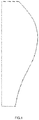
- the structure of the special-shaped plano-convex lens is shown in figure 1 .
- the emitted light will be brighter and it is easy to produce glare.
- researchers usually put an anti-dazzle light cover on the lamp body.
- plano-convex lens can only be placed in the position shown, That is, the convex sphere should be close to the side of the anti-dazzle light cover, and not away from the anti-dazzle light cover.
- the convex sphere of the plano-convex lens occupies a large space, making the distance between the plano-convex lens and the anti-dazzle light cover very close.
- US 7 559 672 B1 discloses a linear illumination lens with Fresnel facets.
- the linear Fresnel lens for LED illumination is configured initially by using a meridional flux-assignment method and is then corrected by assessing the three-dimensional flux distribution of individual facets.
- the facet angles are slightly altered as required to produce uniformity.
- a variety of specialized lens shapes are generated, such as for illuminating shelves in commercial refrigerator food-display cases.
- the lens shapes are suitably thin for economical production by extrusion.
- US 2016/0091173 A1 discloses array-based lighting systems and methods of manufacturing.
- a lighting system includes a substrate, an array of light-emitting diodes (LEDs), and a light cover.
- the array of LEDs is disposed on the substrate and is arranged in a plurality of LED rows and a plurality of LED columns.
- the light cover is positioned over the array of LEDs and includes an array of optical elements. Each optical element is substantially aligned with a LED.
- US 2018/0045933 A1 discloses an optical system and LED wash luminaire employing an lens with a first Fresnel functional surface and a second functional surface comprised of a plurality of out of focus microlenses in bands of different focal lengths in combination with specially shaped reflector(s) to achieve a more even light distribution on a surface area with a wide range of distances from the luminaire.
- US 2016/0146426 A1 discloses a lens for a illuminating device.
- the lens includes a lens portion, an outer periphery and a prism portion.
- the lens portion is disposed at a middle portion of the lens, has an outline that is non-circular, and includes at least one curved surface.
- the outer periphery surrounds the lens portion.
- the prism portion is disposed between the lens portion and the outer periphery, and includes at least two undulated sections. Each undulated section has at least one undulated surface.
- the present invention provides a lighting system according to claim 1.
- the lighting system uses microarray lens for illumination, the height of the lens is reduced, and then the distance between the lens and the anti-dazzle light cover becomes longer, so as to reduce the light blocked by the anti-dazzle light cover and improve the efficiency of the whole lamp.
- a lighting system comprising: microarray lens; light source at the light incoming side of the microarray lens and anti-dazzle light cover above the front end of the light outgoing side, wherein the microarray lens is an asymmetric Fresnel lens and wherein the surface of the light outgoing side of the microarray lens is provided with several strips with different structures distributed up and down crosswise.
- the invention is characterized in that at least one of the strips is formed from top to bottom with a positive curvature towards the lower end of the microarray lens, and at least one other of the strips is formed towards the upper end of the microarray lens with positive curvature, and at least yet another one of the strips is formed towards the lower end of the microarray lens with negative curvature.
- the at least one strip at the upper end of the microarray lens is convex lens structure, and the other at least one strip at the lower end of the microarray lens is concave lens structure.
- the strips change from top to bottom with a positive curvature that decreases first and then increases in curvature, and then changes with a negative curvature that increases in absolute value.
- the light source is LED light source.
- the microarray lens is arranged in parallel with the LED light source in the length direction of the LED light source.
- the advantages of the invention is: flat convex lens will ever replace asymmetric Fresnel lens, Fresnel lenses are thinner than convex lenses, thus the distance between lens and anti-dazzle light cover increases, the light refracted through the lens is further away from the anti-dazzle light cover, reducing the amount of light falling on the anti-dazzle light cover, that is, less light is blocked by the anti-dazzle light cover, and more light is available, thus improve the efficiency of the whole lamp light, and ensure the effect of anti-dazzle at the same time.
- FIG. 2-4 shows an embodiment of the microarray lens and corresponding lighting system in this application.
- most lighting systems use LED as the light source in many fields.
- this application is illustrated with the LED lighting system used in the refrigerator as an example. It can be thought that one or more lighting systems can be used for the refrigerator lighting. Only one lighting system and the corresponding microarray lens are explained here.
- the microarray lens applied in this present invention adopts asymmetric design.
- the installation angle and position of lamp body and the lens is also different. in the freezer, Since the light is deflected downward, that means the light has to come out of the top, so the upper portion of the lighting lens should be designed to have a positive refractive power, so that the light from the light source can be gathered into more distant.
- the microarray lens comprises light incoming side of a smooth surface and light outgoing side with a concave and convex arrangement.
- the microarray lens 2 comprises light incoming side 21 located in front of an LED light source and light outgoing side 22 located behind the anti-dazzle light cover 3.
- the surface of the light outgoing side 22 is provided with several strips 23 with different structures distributed up and down, thereby forming asymmetric Fresnel lens. It should be noted that the structure of the strip is different from that of the strip, which may include different thickness, different direction of bending forming, different curvature and so on.
- the strips 23 on microarray lens 2 in this example are shaped with different curvature (see strips 23a, 23b and 23c) and the shaping direction is also different, and the root width of each strip is also different, thus forming an asymmetric Fresnel lens structure.
- the specific structure of the strips will be described in detail below.
- the strips 23 on the lens looks like sawteeth in the side view.
- microarray lens 2 is set parallel to LED light source 1 in length direction so as to receive as much light from LED as possible.
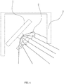
- the LED light source 1 and the microarray lens 2 are installed at a certain angle, as shown in figure 4 .
- the inclined installation angle can be a range, and the included angle between the light source and the microarray lens can also be arranged in a non-parallel way. No matter which installation angle, as long as it finally meets the light irradiation requirements of the refrigerator. At the same time, it can be determined that the inclined installation angle and the angle between the light source and the microarray lens may be different due to the different objects used, which is not the focus of this present invention, so it is not explained in detail here.
- the anti-dazzle light cover 3 of the lighting system is disposed above the front end of the light outgoing side 22 of the microarray lens 2, as in the prior art, with reference to FIG. 5 .
- the sawteeth on the microarray lens 2 is gradually dense from top to bottom, and the molding direction is gradually changed. Specifically, the sawteeth surface changes from the top to the bottom with a positive curvature, and is formed toward the lower end of the lens to form a convex lens, which is then positive.
- the curvature changes and is formed toward the upper end of the lens to form a convex lens, which is then changed with a negative curvature and shaped toward the lower end of the lens to form a concave lens.
- the sawteeth on the upper end can project the LED light beam to the far side due to the focusing effect, while the sawteeth on the lower end aims the light beam of the LED light source towards the near side due to the scattering effect, so as to achieve uniform irradiation on the irradiation surface.
- the strong light emitted from the upper end is easy to generate glare, and he anti-dazzle light cover 3 is disposed at the front end of the light outgoing side 22 to effectively block part of the light, so as to reduce the visual pressure and discomfort caused by excessive light.
- the convex curved surface of the plano-convex lens is close to the anti-dazzle light cover.
- the thickness of the microarray lens 2 is thin, as shown in FIG. 4 , so that the distance between the lens and the anti-dazzle light cover 3 becomes larger, and at the same time, since the sawteeth at upper end of the lens is shaped toward the lower end of the lens.
- the light emitted angle is also more downward than that of the plano-convex lens, so that the light blocked by the anti-dazzle light cover is less, in other words, the amount of light that can be projected onto the illuminated surface is increased, and the illumination is improved, and the high light efficiency performance of the lighting system is also better play.
- the Fresnel lens is more material-saving and less expensive to manufacture than a plano-convex lens.
- the degree of the sawteeth in the microarray lens 2 is biased toward the lower end or the upper end of the lens, that is, the curvature of the serrated surface can be freely set as needed. If excessive illumination is not desired, the sawteeth surface at the upper end of the lens can be made with a small curvature toward the direction of the lower end of the lens changes. If more illumination is desired, the sawteeth surface can be changed toward the lower end of the lens with a large curvature.
- the curved surface of the sawtooth changes with a positive curvature that decreases first and then increases, and then changes with a negative curvature that increases with an absolute value.
- the distance between the anti-dazzle light cover and the microarray lens can also be adjusted and selected during installation to further meet different lighting requirements.
- whether the strip of the microarray lens forms a similar convex lens on the upper end of the lens or a similar convex lens on the lower end of the lens, or whether the upper and lower strip of the microarray lens is a similar convex lens can also be determined according to the actual object, scene and light requirements, it will not be expanded in detail here.
Landscapes
- Engineering & Computer Science (AREA)
- General Engineering & Computer Science (AREA)
- Physics & Mathematics (AREA)
- Optics & Photonics (AREA)
- Microelectronics & Electronic Packaging (AREA)
- General Physics & Mathematics (AREA)
- Chemical & Material Sciences (AREA)
- Combustion & Propulsion (AREA)
- Mechanical Engineering (AREA)
- Thermal Sciences (AREA)
- Non-Portable Lighting Devices Or Systems Thereof (AREA)
Description
- This application claims priority to a Chinese Patent Application No.
CN 201810727324.3, filed on July 4, 2018 - The present invention relates to the field of optics, with particular emphasis on a LED lighting system.
- LED lamps are widely used in daily life, especially in the field of household appliances, because of their advantages of low voltage, high luminous efficiency, pure color and no impurities.
- For example, refrigerating cabinet acts as an indispensable appliance in People's Daily life, LED lighting is widely used in the refrigerating cabinet. In order to achieve good lighting, most LED lights need to be processed by a special-shaped plano-convex lens before being emitted. The structure of the special-shaped plano-convex lens is shown in
figure 1 . However, due to the convergent effect of a plano-convex lens, the emitted light will be brighter and it is easy to produce glare. To solve this problem, researchers usually put an anti-dazzle light cover on the lamp body. - However, this brings another problem. Due to the limitation of the width of the lamp body and the anti-dazzle light cover, the anti-dazzle light cover blocks part of the light, making the overall lighting effect low and insufficient. As shown in
figure 5 , due to meet the uniform illumination, plano-convex lens can only be placed in the position shown, That is, the convex sphere should be close to the side of the anti-dazzle light cover, and not away from the anti-dazzle light cover. The convex sphere of the plano-convex lens occupies a large space, making the distance between the plano-convex lens and the anti-dazzle light cover very close. When the LED light is emitted from the lens, part of the light will be blocked by the anti-dazzle light cover, resulting in less light available and affecting the illumination. -
US 7 559 672 B1 discloses a linear illumination lens with Fresnel facets. The linear Fresnel lens for LED illumination is configured initially by using a meridional flux-assignment method and is then corrected by assessing the three-dimensional flux distribution of individual facets. The facet angles are slightly altered as required to produce uniformity. A variety of specialized lens shapes are generated, such as for illuminating shelves in commercial refrigerator food-display cases. The lens shapes are suitably thin for economical production by extrusion. -
US 2016/0091173 A1 discloses array-based lighting systems and methods of manufacturing. Such a lighting system includes a substrate, an array of light-emitting diodes (LEDs), and a light cover. The array of LEDs is disposed on the substrate and is arranged in a plurality of LED rows and a plurality of LED columns. The light cover is positioned over the array of LEDs and includes an array of optical elements. Each optical element is substantially aligned with a LED. -
US 2018/0045933 A1 discloses an optical system and LED wash luminaire employing an lens with a first Fresnel functional surface and a second functional surface comprised of a plurality of out of focus microlenses in bands of different focal lengths in combination with specially shaped reflector(s) to achieve a more even light distribution on a surface area with a wide range of distances from the luminaire. -
US 2016/0146426 A1 discloses a lens for a illuminating device. The lens includes a lens portion, an outer periphery and a prism portion. The lens portion is disposed at a middle portion of the lens, has an outline that is non-circular, and includes at least one curved surface. The outer periphery surrounds the lens portion. The prism portion is disposed between the lens portion and the outer periphery, and includes at least two undulated sections. Each undulated section has at least one undulated surface. - Therefore, the present invention provides a lighting system according to
claim 1. The lighting system uses microarray lens for illumination, the height of the lens is reduced, and then the distance between the lens and the anti-dazzle light cover becomes longer, so as to reduce the light blocked by the anti-dazzle light cover and improve the efficiency of the whole lamp. - The technical solution adopted by the present invention to solve the above problems is as follows: A lighting system, comprising: microarray lens; light source at the light incoming side of the microarray lens and anti-dazzle light cover above the front end of the light outgoing side, wherein the microarray lens is an asymmetric Fresnel lens and wherein the surface of the light outgoing side of the microarray lens is provided with several strips with different structures distributed up and down crosswise.
- The invention is characterized in that at least one of the strips is formed from top to bottom with a positive curvature towards the lower end of the microarray lens, and at least one other of the strips is formed towards the upper end of the microarray lens with positive curvature, and at least yet another one of the strips is formed towards the lower end of the microarray lens with negative curvature.
- Preferred embodiment may have the following features:
- The at least one strip at the upper end of the microarray lens is convex lens structure, and the other at least one strip at the lower end of the microarray lens is concave lens structure.
- The strips change from top to bottom with a positive curvature that decreases first and then increases in curvature, and then changes with a negative curvature that increases in absolute value.
- The light source is LED light source.
- The microarray lens is arranged in parallel with the LED light source in the length direction of the LED light source.
- Compared with the existing technology, the advantages of the invention is: flat convex lens will ever replace asymmetric Fresnel lens, Fresnel lenses are thinner than convex lenses, thus the distance between lens and anti-dazzle light cover increases, the light refracted through the lens is further away from the anti-dazzle light cover, reducing the amount of light falling on the anti-dazzle light cover, that is, less light is blocked by the anti-dazzle light cover, and more light is available, thus improve the efficiency of the whole lamp light, and ensure the effect of anti-dazzle at the same time.
- The drawings described herein are intended to promote a further understanding of the present invention, as follows:
-
FIG. 1 is a schematic diagram of plano-convex lens structure of the prior art. -
FIG. 2 is a schematic diagram of a frontal structure of an embodiment of a microarray lens of the present invention. -
FIG. 3 is a side view offigure 2 . -
FIG. 4 is a light path rendering of an embodiment of the corresponding lighting system of the present invention. -
Figure 5 is a rendering of the lighting system in the existing technology. - The present application is illustrated by way of the following detailed description based on of the accompanying drawings. It should be noted that illustration to the embodiment in this application is not intended to limit the invention.
- For introductory interpretation,
FIG. 2-4 shows an embodiment of the microarray lens and corresponding lighting system in this application. At present, most lighting systems use LED as the light source in many fields. In order to facilitate the explanation, this application is illustrated with the LED lighting system used in the refrigerator as an example. It can be thought that one or more lighting systems can be used for the refrigerator lighting. Only one lighting system and the corresponding microarray lens are explained here. - According to Fresnel lens design principle, the microarray lens applied in this present invention adopts asymmetric design. Depend on different lighting system using field, the installation angle and position of lamp body and the lens is also different. in the freezer, Since the light is deflected downward, that means the light has to come out of the top, so the upper portion of the lighting lens should be designed to have a positive refractive power, so that the light from the light source can be gathered into more distant.
- The microarray lens comprises light incoming side of a smooth surface and light outgoing side with a concave and convex arrangement. in this example, the
microarray lens 2 comprises lightincoming side 21 located in front of an LED light source and lightoutgoing side 22 located behind theanti-dazzle light cover 3. The surface of the lightoutgoing side 22 is provided withseveral strips 23 with different structures distributed up and down, thereby forming asymmetric Fresnel lens. It should be noted that the structure of the strip is different from that of the strip, which may include different thickness, different direction of bending forming, different curvature and so on. - Specific to this embodiment, as shown in
FIG. 2 and4 , thestrips 23 onmicroarray lens 2 in this example are shaped with different curvature (seestrips figure 3 , thestrips 23 on the lens looks like sawteeth in the side view. - In this embodiment, as shown in
FIG. 4 ,microarray lens 2 is set parallel toLED light source 1 in length direction so as to receive as much light from LED as possible. In order to fit the internal structure of the refrigerator and meet the light requirements, the LEDlight source 1 and themicroarray lens 2 are installed at a certain angle, as shown infigure 4 . - It can be thought that the inclined installation angle can be a range, and the included angle between the light source and the microarray lens can also be arranged in a non-parallel way. No matter which installation angle, as long as it finally meets the light irradiation requirements of the refrigerator. At the same time, it can be determined that the inclined installation angle and the angle between the light source and the microarray lens may be different due to the different objects used, which is not the focus of this present invention, so it is not explained in detail here.
- Continue to see
FIG. 3 andFIG. 4 . In this embodiment, the anti-dazzlelight cover 3 of the lighting system is disposed above the front end of the lightoutgoing side 22 of themicroarray lens 2, as in the prior art, with reference toFIG. 5 . The sawteeth on themicroarray lens 2 is gradually dense from top to bottom, and the molding direction is gradually changed. Specifically, the sawteeth surface changes from the top to the bottom with a positive curvature, and is formed toward the lower end of the lens to form a convex lens, which is then positive. The curvature changes and is formed toward the upper end of the lens to form a convex lens, which is then changed with a negative curvature and shaped toward the lower end of the lens to form a concave lens. - When
microarray lens 2 changes with this trend, the sawteeth on the upper end can project the LED light beam to the far side due to the focusing effect, while the sawteeth on the lower end aims the light beam of the LED light source towards the near side due to the scattering effect, so as to achieve uniform irradiation on the irradiation surface. It is based on this that the strong light emitted from the upper end is easy to generate glare, and he anti-dazzlelight cover 3 is disposed at the front end of the lightoutgoing side 22 to effectively block part of the light, so as to reduce the visual pressure and discomfort caused by excessive light. - please refer to
figure 4 andfigure 5 together. As shown infigure 5 , the convex curved surface of the plano-convex lens is close to the anti-dazzle light cover. When the light is emitted from the convex curved surface, part of the light is blocked by the anti-dazzle light cover. Compared with the plano-convex lens, the thickness of themicroarray lens 2 is thin, as shown inFIG. 4 , so that the distance between the lens and the anti-dazzlelight cover 3 becomes larger, and at the same time, since the sawteeth at upper end of the lens is shaped toward the lower end of the lens. the light emitted angle is also more downward than that of the plano-convex lens, so that the light blocked by the anti-dazzle light cover is less, in other words, the amount of light that can be projected onto the illuminated surface is increased, and the illumination is improved, and the high light efficiency performance of the lighting system is also better play. Moreover, the Fresnel lens is more material-saving and less expensive to manufacture than a plano-convex lens. - It is easy to think that the degree of the sawteeth in the
microarray lens 2 is biased toward the lower end or the upper end of the lens, that is, the curvature of the serrated surface can be freely set as needed. If excessive illumination is not desired, the sawteeth surface at the upper end of the lens can be made with a small curvature toward the direction of the lower end of the lens changes. If more illumination is desired, the sawteeth surface can be changed toward the lower end of the lens with a large curvature. In the present embodiment, the curved surface of the sawtooth changes with a positive curvature that decreases first and then increases, and then changes with a negative curvature that increases with an absolute value. - Understandably, the distance between the anti-dazzle light cover and the microarray lens can also be adjusted and selected during installation to further meet different lighting requirements. In addition, whether the strip of the microarray lens forms a similar convex lens on the upper end of the lens or a similar convex lens on the lower end of the lens, or whether the upper and lower strip of the microarray lens is a similar convex lens, can also be determined according to the actual object, scene and light requirements, it will not be expanded in detail here.
- The above disclosure has been described by way of example and in terms of exemplary embodiment, and it is to be understood that the disclosure is not limited thereto.
Claims (5)
- A lighting system, comprising:microarray lens (2);light source (1) at the light incoming side (21) of the microarray lens (2) and anti-dazzle light cover (3) above the front end of the light outgoing side (22);wherein the microarray lens (2) is an asymmetric Fresnel lens,wherein the surface of the light outgoing side (22) of the microarray lens (2) is providedwith several strips (23) with different structures distributed up and down crosswise,characterized in thatat least one (23a) of the strips (23) is formed from top to bottom with a positive curvature towards the lower end of the microarray lens (2), and at least one other (23b) of the strips (23) is formed towards the upper end of the microarray lens (2) with positive curvature, and at least yet another one (23c) of the strips (23) is formed towards the lower end of the microarray lens (2) with negative curvature.
- The lighting system as claimed in claim 1, wherein the at least one strip (23a) at the upper end of the microarray lens (2) is convex lens structure, and the at least one strip (23c) at the lower end of the microarray lens (2) is concave lens structure.
- The lighting system as claimed in claim 1, wherein the strips (23) change from top to bottom with a positive curvature that decreases first and then increases in curvature, and then changes with a negative curvature that increases in absolute value.
- The lighting system as claimed in claim 1, wherein the light source (1) is LED light source.
- The lighting system as claimed in claim 4, wherein the microarray lens (2) is arranged in parallel with the LED light source in the length direction of the LED light source.
Applications Claiming Priority (1)
| Application Number | Priority Date | Filing Date | Title |
|---|---|---|---|
| CN201810727324.3A CN108954044A (en) | 2018-07-04 | 2018-07-04 | A kind of lighting system |
Publications (2)
| Publication Number | Publication Date |
|---|---|
| EP3591283A1 EP3591283A1 (en) | 2020-01-08 |
| EP3591283B1 true EP3591283B1 (en) | 2021-09-22 |
Family
ID=64485781
Family Applications (1)
| Application Number | Title | Priority Date | Filing Date |
|---|---|---|---|
| EP19184529.6A Active EP3591283B1 (en) | 2018-07-04 | 2019-07-04 | Lighting system |
Country Status (3)
| Country | Link |
|---|---|
| US (1) | US20200011504A1 (en) |
| EP (1) | EP3591283B1 (en) |
| CN (1) | CN108954044A (en) |
Families Citing this family (2)
| Publication number | Priority date | Publication date | Assignee | Title |
|---|---|---|---|---|
| US11441749B2 (en) * | 2019-04-04 | 2022-09-13 | Fusion Optix, Inc. | Lighting assembly for electrically adjustable light distributions |
| CN110375262B (en) * | 2019-08-15 | 2024-05-24 | 嘉善声光电子有限公司 | Lighting and light distribution system of bicycle lamp and bicycle lamp |
Family Cites Families (25)
| Publication number | Priority date | Publication date | Assignee | Title |
|---|---|---|---|---|
| JP4360945B2 (en) * | 2004-03-10 | 2009-11-11 | シチズン電子株式会社 | Lighting device |
| TWI291573B (en) * | 2004-12-24 | 2007-12-21 | Prodisc Technology Inc | Liquid crystal display and backlight module |
| US8163580B2 (en) * | 2005-08-10 | 2012-04-24 | Philips Lumileds Lighting Company Llc | Multiple die LED and lens optical system |
| CN101290095B (en) * | 2007-04-18 | 2011-02-16 | 财团法人工业技术研究院 | Desk lamp with anti-glare function |
| US7559672B1 (en) * | 2007-06-01 | 2009-07-14 | Inteled Corporation | Linear illumination lens with Fresnel facets |
| US8368729B2 (en) * | 2007-11-22 | 2013-02-05 | Sharp Kabushiki Kaisha | Display device |
| CN101561115B (en) * | 2009-04-08 | 2012-07-25 | 上海三思电子工程有限公司 | Design method of ultra-thin lens used for LED |
| CN201396698Y (en) * | 2009-04-09 | 2010-02-03 | 上海三思电子工程有限公司 | Ultra-thin lens for LED wall washer |
| US8162512B2 (en) * | 2009-09-10 | 2012-04-24 | Entire Technology Co., Ltd. | Optical sheet, manufacturing method thereof, and backlight assembly using the same |
| CN201651923U (en) * | 2010-04-14 | 2010-11-24 | 林万炯 | LED light with Fresnel lens |
| TWI452360B (en) * | 2010-12-10 | 2014-09-11 | Ind Tech Res Inst | Collimating optical element, collimating optical assembly, collimating optical array and collimating optical module |
| US9902265B2 (en) * | 2011-05-13 | 2018-02-27 | Volkswagen Ag | Display device for a vehicle, and vehicle |
| KR101909602B1 (en) * | 2011-08-17 | 2018-10-18 | 엘지전자 주식회사 | Mobile terminal |
| US8833978B2 (en) * | 2011-10-25 | 2014-09-16 | Leotek Electronics Corporation | Traffic signal light device |
| US10222029B2 (en) * | 2014-09-30 | 2019-03-05 | The Boeing Company | Array-based lighting systems and methods of manufacturing |
| TWI537609B (en) * | 2014-11-21 | 2016-06-11 | 玉晶光電股份有限公司 | Thinner type lens |
| TWI537608B (en) * | 2014-11-21 | 2016-06-11 | 玉晶光電股份有限公司 | Thinner type lens |
| CN104976585A (en) * | 2015-06-29 | 2015-10-14 | 赛尔富电子有限公司 | Strip-shaped spreadlight lens and LED strip light |
| TWI551892B (en) * | 2015-09-02 | 2016-10-01 | 原相科技股份有限公司 | Multi-segment Optical Component and Related Optical Detecting Device Capable of Increasing SNR |
| US10278295B2 (en) * | 2015-09-25 | 2019-04-30 | Lg Display Co., Ltd. | Frame-type optical member with optical fiber and multi-panel display device with same |
| US20180045933A1 (en) * | 2016-06-30 | 2018-02-15 | Danielle Dileo | Optical system for an led wash luminaire |
| WO2018088342A1 (en) * | 2016-11-09 | 2018-05-17 | シャープ株式会社 | Display apparatus and head-mounted display |
| CN106439566B (en) * | 2016-11-22 | 2024-05-31 | 赛尔富电子有限公司 | LED strip-shaped lamp |
| US20190195455A1 (en) * | 2017-12-22 | 2019-06-27 | Industrial Technology Research Institute | Headlight device |
| CN208804489U (en) * | 2018-07-04 | 2019-04-30 | 赛尔富电子有限公司 | A kind of lighting system |
-
2018
- 2018-07-04 CN CN201810727324.3A patent/CN108954044A/en active Pending
-
2019
- 2019-06-11 US US16/438,254 patent/US20200011504A1/en not_active Abandoned
- 2019-07-04 EP EP19184529.6A patent/EP3591283B1/en active Active
Also Published As
| Publication number | Publication date |
|---|---|
| EP3591283A1 (en) | 2020-01-08 |
| US20200011504A1 (en) | 2020-01-09 |
| CN108954044A (en) | 2018-12-07 |
Similar Documents
| Publication | Publication Date | Title |
|---|---|---|
| US8075157B2 (en) | LED module | |
| US8434914B2 (en) | Lens generating a batwing-shaped beam distribution, and method therefor | |
| US12025304B2 (en) | Optics for chip-on-board road and area lighting | |
| US8911118B2 (en) | Lens, LED module and illumination system having same | |
| JP5951626B2 (en) | Expandable icicle type light adjustment lens for LED light diffusion | |
| US9360169B2 (en) | Lens, LED module and illumination system with asymmetric lighting distribution | |
| US10648644B2 (en) | Optics for chip-on-board lighting having a protrusion | |
| EP2708804A1 (en) | Lens, LED module and illumination system having same | |
| TW201523033A (en) | Omnidirectional light emitting diode lens | |
| CN112254026A (en) | Anti-dazzle lamp and lighting arrangement method adopting same | |
| US20200011504A1 (en) | Lighting System | |
| RU2689329C2 (en) | Lighting device, especially for road lighting | |
| CN208804489U (en) | A kind of lighting system | |
| CN110242933A (en) | A kind of LED tri-proof light | |
| CN210241460U (en) | Strip lens | |
| CN209460444U (en) | A kind of two-way asymmetrical beam grid and lighting system | |
| KR101149580B1 (en) | Diffusion type reflector for light adjusting of led | |
| CN202040632U (en) | LED plane light source device | |
| CN212719578U (en) | Low-glare lens and lamp | |
| WO2012014239A1 (en) | Optical system for uniform distribution of light emitted by light sources | |
| CN104344345A (en) | Lens and light source module using same | |
| KR101742196B1 (en) | Lens of light diffusion for LED device | |
| KR101891431B1 (en) | Illumination lens for led and linear illumination apparatus using the same | |
| KR20200034537A (en) | LED search light lens and LED search light using the same |
Legal Events
| Date | Code | Title | Description |
|---|---|---|---|
| PUAI | Public reference made under article 153(3) epc to a published international application that has entered the european phase |
Free format text: ORIGINAL CODE: 0009012 |
|
| STAA | Information on the status of an ep patent application or granted ep patent |
Free format text: STATUS: THE APPLICATION HAS BEEN PUBLISHED |
|
| AK | Designated contracting states |
Kind code of ref document: A1 Designated state(s): AL AT BE BG CH CY CZ DE DK EE ES FI FR GB GR HR HU IE IS IT LI LT LU LV MC MK MT NL NO PL PT RO RS SE SI SK SM TR |
|
| AX | Request for extension of the european patent |
Extension state: BA ME |
|
| STAA | Information on the status of an ep patent application or granted ep patent |
Free format text: STATUS: REQUEST FOR EXAMINATION WAS MADE |
|
| 17P | Request for examination filed |
Effective date: 20200930 |
|
| RBV | Designated contracting states (corrected) |
Designated state(s): AL AT BE BG CH CY CZ DE DK EE ES FI FR GB GR HR HU IE IS IT LI LT LU LV MC MK MT NL NO PL PT RO RS SE SI SK SM TR |
|
| RIC1 | Information provided on ipc code assigned before grant |
Ipc: F21Y 115/10 20160101ALN20210419BHEP Ipc: F21Y 103/10 20160101ALN20210419BHEP Ipc: F21W 131/305 20060101ALN20210419BHEP Ipc: F25D 27/00 20060101ALI20210419BHEP Ipc: G02B 19/00 20060101ALI20210419BHEP Ipc: G02B 3/08 20060101ALI20210419BHEP Ipc: F21V 5/00 20180101ALI20210419BHEP Ipc: F21V 5/08 20060101ALI20210419BHEP Ipc: F21V 5/04 20060101AFI20210419BHEP |
|
| RIC1 | Information provided on ipc code assigned before grant |
Ipc: F21Y 115/10 20160101ALN20210506BHEP Ipc: F21Y 103/10 20160101ALN20210506BHEP Ipc: F21W 131/305 20060101ALN20210506BHEP Ipc: F25D 27/00 20060101ALI20210506BHEP Ipc: G02B 19/00 20060101ALI20210506BHEP Ipc: G02B 3/08 20060101ALI20210506BHEP Ipc: F21V 5/00 20180101ALI20210506BHEP Ipc: F21V 5/08 20060101ALI20210506BHEP Ipc: F21V 5/04 20060101AFI20210506BHEP |
|
| GRAP | Despatch of communication of intention to grant a patent |
Free format text: ORIGINAL CODE: EPIDOSNIGR1 |
|
| STAA | Information on the status of an ep patent application or granted ep patent |
Free format text: STATUS: GRANT OF PATENT IS INTENDED |
|
| INTG | Intention to grant announced |
Effective date: 20210616 |
|
| RAP3 | Party data changed (applicant data changed or rights of an application transferred) |
Owner name: LIN, WANJIONG Owner name: SELF ELECTRONICS GERMANY GMBH Owner name: SELF ELECTRONICS CO., LTD. |
|
| GRAS | Grant fee paid |
Free format text: ORIGINAL CODE: EPIDOSNIGR3 |
|
| GRAA | (expected) grant |
Free format text: ORIGINAL CODE: 0009210 |
|
| STAA | Information on the status of an ep patent application or granted ep patent |
Free format text: STATUS: THE PATENT HAS BEEN GRANTED |
|
| AK | Designated contracting states |
Kind code of ref document: B1 Designated state(s): AL AT BE BG CH CY CZ DE DK EE ES FI FR GB GR HR HU IE IS IT LI LT LU LV MC MK MT NL NO PL PT RO RS SE SI SK SM TR |
|
| REG | Reference to a national code |
Ref country code: GB Ref legal event code: FG4D |
|
| REG | Reference to a national code |
Ref country code: IE Ref legal event code: FG4D |
|
| REG | Reference to a national code |
Ref country code: DE Ref legal event code: R096 Ref document number: 602019007805 Country of ref document: DE |
|
| REG | Reference to a national code |
Ref country code: CH Ref legal event code: EP Ref country code: AT Ref legal event code: REF Ref document number: 1432611 Country of ref document: AT Kind code of ref document: T Effective date: 20211015 |
|
| REG | Reference to a national code |
Ref country code: LT Ref legal event code: MG9D |
|
| REG | Reference to a national code |
Ref country code: NL Ref legal event code: MP Effective date: 20210922 |
|
| PG25 | Lapsed in a contracting state [announced via postgrant information from national office to epo] |
Ref country code: BG Free format text: LAPSE BECAUSE OF FAILURE TO SUBMIT A TRANSLATION OF THE DESCRIPTION OR TO PAY THE FEE WITHIN THE PRESCRIBED TIME-LIMIT Effective date: 20211222 Ref country code: LT Free format text: LAPSE BECAUSE OF FAILURE TO SUBMIT A TRANSLATION OF THE DESCRIPTION OR TO PAY THE FEE WITHIN THE PRESCRIBED TIME-LIMIT Effective date: 20210922 Ref country code: HR Free format text: LAPSE BECAUSE OF FAILURE TO SUBMIT A TRANSLATION OF THE DESCRIPTION OR TO PAY THE FEE WITHIN THE PRESCRIBED TIME-LIMIT Effective date: 20210922 Ref country code: NO Free format text: LAPSE BECAUSE OF FAILURE TO SUBMIT A TRANSLATION OF THE DESCRIPTION OR TO PAY THE FEE WITHIN THE PRESCRIBED TIME-LIMIT Effective date: 20211222 Ref country code: RS Free format text: LAPSE BECAUSE OF FAILURE TO SUBMIT A TRANSLATION OF THE DESCRIPTION OR TO PAY THE FEE WITHIN THE PRESCRIBED TIME-LIMIT Effective date: 20210922 Ref country code: SE Free format text: LAPSE BECAUSE OF FAILURE TO SUBMIT A TRANSLATION OF THE DESCRIPTION OR TO PAY THE FEE WITHIN THE PRESCRIBED TIME-LIMIT Effective date: 20210922 Ref country code: FI Free format text: LAPSE BECAUSE OF FAILURE TO SUBMIT A TRANSLATION OF THE DESCRIPTION OR TO PAY THE FEE WITHIN THE PRESCRIBED TIME-LIMIT Effective date: 20210922 |
|
| REG | Reference to a national code |
Ref country code: AT Ref legal event code: MK05 Ref document number: 1432611 Country of ref document: AT Kind code of ref document: T Effective date: 20210922 |
|
| PG25 | Lapsed in a contracting state [announced via postgrant information from national office to epo] |
Ref country code: LV Free format text: LAPSE BECAUSE OF FAILURE TO SUBMIT A TRANSLATION OF THE DESCRIPTION OR TO PAY THE FEE WITHIN THE PRESCRIBED TIME-LIMIT Effective date: 20210922 Ref country code: GR Free format text: LAPSE BECAUSE OF FAILURE TO SUBMIT A TRANSLATION OF THE DESCRIPTION OR TO PAY THE FEE WITHIN THE PRESCRIBED TIME-LIMIT Effective date: 20211223 |
|
| PG25 | Lapsed in a contracting state [announced via postgrant information from national office to epo] |
Ref country code: AT Free format text: LAPSE BECAUSE OF FAILURE TO SUBMIT A TRANSLATION OF THE DESCRIPTION OR TO PAY THE FEE WITHIN THE PRESCRIBED TIME-LIMIT Effective date: 20210922 |
|
| PG25 | Lapsed in a contracting state [announced via postgrant information from national office to epo] |
Ref country code: IS Free format text: LAPSE BECAUSE OF FAILURE TO SUBMIT A TRANSLATION OF THE DESCRIPTION OR TO PAY THE FEE WITHIN THE PRESCRIBED TIME-LIMIT Effective date: 20220122 Ref country code: SK Free format text: LAPSE BECAUSE OF FAILURE TO SUBMIT A TRANSLATION OF THE DESCRIPTION OR TO PAY THE FEE WITHIN THE PRESCRIBED TIME-LIMIT Effective date: 20210922 Ref country code: RO Free format text: LAPSE BECAUSE OF FAILURE TO SUBMIT A TRANSLATION OF THE DESCRIPTION OR TO PAY THE FEE WITHIN THE PRESCRIBED TIME-LIMIT Effective date: 20210922 Ref country code: PT Free format text: LAPSE BECAUSE OF FAILURE TO SUBMIT A TRANSLATION OF THE DESCRIPTION OR TO PAY THE FEE WITHIN THE PRESCRIBED TIME-LIMIT Effective date: 20220124 Ref country code: PL Free format text: LAPSE BECAUSE OF FAILURE TO SUBMIT A TRANSLATION OF THE DESCRIPTION OR TO PAY THE FEE WITHIN THE PRESCRIBED TIME-LIMIT Effective date: 20210922 Ref country code: NL Free format text: LAPSE BECAUSE OF FAILURE TO SUBMIT A TRANSLATION OF THE DESCRIPTION OR TO PAY THE FEE WITHIN THE PRESCRIBED TIME-LIMIT Effective date: 20210922 Ref country code: ES Free format text: LAPSE BECAUSE OF FAILURE TO SUBMIT A TRANSLATION OF THE DESCRIPTION OR TO PAY THE FEE WITHIN THE PRESCRIBED TIME-LIMIT Effective date: 20210922 Ref country code: EE Free format text: LAPSE BECAUSE OF FAILURE TO SUBMIT A TRANSLATION OF THE DESCRIPTION OR TO PAY THE FEE WITHIN THE PRESCRIBED TIME-LIMIT Effective date: 20210922 Ref country code: CZ Free format text: LAPSE BECAUSE OF FAILURE TO SUBMIT A TRANSLATION OF THE DESCRIPTION OR TO PAY THE FEE WITHIN THE PRESCRIBED TIME-LIMIT Effective date: 20210922 Ref country code: AL Free format text: LAPSE BECAUSE OF FAILURE TO SUBMIT A TRANSLATION OF THE DESCRIPTION OR TO PAY THE FEE WITHIN THE PRESCRIBED TIME-LIMIT Effective date: 20210922 |
|
| REG | Reference to a national code |
Ref country code: DE Ref legal event code: R097 Ref document number: 602019007805 Country of ref document: DE |
|
| PG25 | Lapsed in a contracting state [announced via postgrant information from national office to epo] |
Ref country code: DK Free format text: LAPSE BECAUSE OF FAILURE TO SUBMIT A TRANSLATION OF THE DESCRIPTION OR TO PAY THE FEE WITHIN THE PRESCRIBED TIME-LIMIT Effective date: 20210922 |
|
| PLBE | No opposition filed within time limit |
Free format text: ORIGINAL CODE: 0009261 |
|
| STAA | Information on the status of an ep patent application or granted ep patent |
Free format text: STATUS: NO OPPOSITION FILED WITHIN TIME LIMIT |
|
| 26N | No opposition filed |
Effective date: 20220623 |
|
| PG25 | Lapsed in a contracting state [announced via postgrant information from national office to epo] |
Ref country code: SI Free format text: LAPSE BECAUSE OF FAILURE TO SUBMIT A TRANSLATION OF THE DESCRIPTION OR TO PAY THE FEE WITHIN THE PRESCRIBED TIME-LIMIT Effective date: 20210922 |
|
| PG25 | Lapsed in a contracting state [announced via postgrant information from national office to epo] |
Ref country code: IT Free format text: LAPSE BECAUSE OF FAILURE TO SUBMIT A TRANSLATION OF THE DESCRIPTION OR TO PAY THE FEE WITHIN THE PRESCRIBED TIME-LIMIT Effective date: 20210922 |
|
| PG25 | Lapsed in a contracting state [announced via postgrant information from national office to epo] |
Ref country code: MC Free format text: LAPSE BECAUSE OF FAILURE TO SUBMIT A TRANSLATION OF THE DESCRIPTION OR TO PAY THE FEE WITHIN THE PRESCRIBED TIME-LIMIT Effective date: 20210922 |
|
| REG | Reference to a national code |
Ref country code: CH Ref legal event code: PL |
|
| REG | Reference to a national code |
Ref country code: BE Ref legal event code: MM Effective date: 20220731 |
|
| PG25 | Lapsed in a contracting state [announced via postgrant information from national office to epo] |
Ref country code: LU Free format text: LAPSE BECAUSE OF NON-PAYMENT OF DUE FEES Effective date: 20220704 Ref country code: LI Free format text: LAPSE BECAUSE OF NON-PAYMENT OF DUE FEES Effective date: 20220731 Ref country code: FR Free format text: LAPSE BECAUSE OF NON-PAYMENT OF DUE FEES Effective date: 20220731 Ref country code: CH Free format text: LAPSE BECAUSE OF NON-PAYMENT OF DUE FEES Effective date: 20220731 |
|
| PG25 | Lapsed in a contracting state [announced via postgrant information from national office to epo] |
Ref country code: BE Free format text: LAPSE BECAUSE OF NON-PAYMENT OF DUE FEES Effective date: 20220731 |
|
| PG25 | Lapsed in a contracting state [announced via postgrant information from national office to epo] |
Ref country code: IE Free format text: LAPSE BECAUSE OF NON-PAYMENT OF DUE FEES Effective date: 20220704 |
|
| GBPC | Gb: european patent ceased through non-payment of renewal fee |
Effective date: 20230704 |
|
| PG25 | Lapsed in a contracting state [announced via postgrant information from national office to epo] |
Ref country code: HU Free format text: LAPSE BECAUSE OF FAILURE TO SUBMIT A TRANSLATION OF THE DESCRIPTION OR TO PAY THE FEE WITHIN THE PRESCRIBED TIME-LIMIT; INVALID AB INITIO Effective date: 20190704 |
|
| PG25 | Lapsed in a contracting state [announced via postgrant information from national office to epo] |
Ref country code: SM Free format text: LAPSE BECAUSE OF FAILURE TO SUBMIT A TRANSLATION OF THE DESCRIPTION OR TO PAY THE FEE WITHIN THE PRESCRIBED TIME-LIMIT Effective date: 20210922 Ref country code: MK Free format text: LAPSE BECAUSE OF FAILURE TO SUBMIT A TRANSLATION OF THE DESCRIPTION OR TO PAY THE FEE WITHIN THE PRESCRIBED TIME-LIMIT Effective date: 20210922 Ref country code: CY Free format text: LAPSE BECAUSE OF FAILURE TO SUBMIT A TRANSLATION OF THE DESCRIPTION OR TO PAY THE FEE WITHIN THE PRESCRIBED TIME-LIMIT Effective date: 20210922 Ref country code: GB Free format text: LAPSE BECAUSE OF NON-PAYMENT OF DUE FEES Effective date: 20230704 |
|
| PG25 | Lapsed in a contracting state [announced via postgrant information from national office to epo] |
Ref country code: TR Free format text: LAPSE BECAUSE OF FAILURE TO SUBMIT A TRANSLATION OF THE DESCRIPTION OR TO PAY THE FEE WITHIN THE PRESCRIBED TIME-LIMIT Effective date: 20210922 |
|
| PG25 | Lapsed in a contracting state [announced via postgrant information from national office to epo] |
Ref country code: MT Free format text: LAPSE BECAUSE OF FAILURE TO SUBMIT A TRANSLATION OF THE DESCRIPTION OR TO PAY THE FEE WITHIN THE PRESCRIBED TIME-LIMIT Effective date: 20210922 |
|
| PGFP | Annual fee paid to national office [announced via postgrant information from national office to epo] |
Ref country code: DE Payment date: 20250731 Year of fee payment: 7 |