EP3591261B1 - Four-speed transaxle for high efficiency electric vehicle - Google Patents
Four-speed transaxle for high efficiency electric vehicle Download PDFInfo
- Publication number
- EP3591261B1 EP3591261B1 EP19193979.2A EP19193979A EP3591261B1 EP 3591261 B1 EP3591261 B1 EP 3591261B1 EP 19193979 A EP19193979 A EP 19193979A EP 3591261 B1 EP3591261 B1 EP 3591261B1
- Authority
- EP
- European Patent Office
- Prior art keywords
- gear
- shifting
- brake system
- electric
- shift
- Prior art date
- Legal status (The legal status is an assumption and is not a legal conclusion. Google has not performed a legal analysis and makes no representation as to the accuracy of the status listed.)
- Active
Links
Images








Classifications
-
- B—PERFORMING OPERATIONS; TRANSPORTING
- B60—VEHICLES IN GENERAL
- B60K—ARRANGEMENT OR MOUNTING OF PROPULSION UNITS OR OF TRANSMISSIONS IN VEHICLES; ARRANGEMENT OR MOUNTING OF PLURAL DIVERSE PRIME-MOVERS IN VEHICLES; AUXILIARY DRIVES FOR VEHICLES; INSTRUMENTATION OR DASHBOARDS FOR VEHICLES; ARRANGEMENTS IN CONNECTION WITH COOLING, AIR INTAKE, GAS EXHAUST OR FUEL SUPPLY OF PROPULSION UNITS IN VEHICLES
- B60K1/00—Arrangement or mounting of electrical propulsion units
-
- F—MECHANICAL ENGINEERING; LIGHTING; HEATING; WEAPONS; BLASTING
- F16—ENGINEERING ELEMENTS AND UNITS; GENERAL MEASURES FOR PRODUCING AND MAINTAINING EFFECTIVE FUNCTIONING OF MACHINES OR INSTALLATIONS; THERMAL INSULATION IN GENERAL
- F16H—GEARING
- F16H37/00—Combinations of mechanical gearings, not provided for in groups F16H1/00 - F16H35/00
- F16H37/02—Combinations of mechanical gearings, not provided for in groups F16H1/00 - F16H35/00 comprising essentially only toothed or friction gearings
- F16H37/06—Combinations of mechanical gearings, not provided for in groups F16H1/00 - F16H35/00 comprising essentially only toothed or friction gearings with a plurality of driving or driven shafts; with arrangements for dividing torque between two or more intermediate shafts
- F16H37/08—Combinations of mechanical gearings, not provided for in groups F16H1/00 - F16H35/00 comprising essentially only toothed or friction gearings with a plurality of driving or driven shafts; with arrangements for dividing torque between two or more intermediate shafts with differential gearing
- F16H37/0806—Combinations of mechanical gearings, not provided for in groups F16H1/00 - F16H35/00 comprising essentially only toothed or friction gearings with a plurality of driving or driven shafts; with arrangements for dividing torque between two or more intermediate shafts with differential gearing with a plurality of driving or driven shafts
- F16H37/0813—Combinations of mechanical gearings, not provided for in groups F16H1/00 - F16H35/00 comprising essentially only toothed or friction gearings with a plurality of driving or driven shafts; with arrangements for dividing torque between two or more intermediate shafts with differential gearing with a plurality of driving or driven shafts with only one input shaft
- F16H37/082—Combinations of mechanical gearings, not provided for in groups F16H1/00 - F16H35/00 comprising essentially only toothed or friction gearings with a plurality of driving or driven shafts; with arrangements for dividing torque between two or more intermediate shafts with differential gearing with a plurality of driving or driven shafts with only one input shaft and additional planetary reduction gears
-
- B—PERFORMING OPERATIONS; TRANSPORTING
- B60—VEHICLES IN GENERAL
- B60K—ARRANGEMENT OR MOUNTING OF PROPULSION UNITS OR OF TRANSMISSIONS IN VEHICLES; ARRANGEMENT OR MOUNTING OF PLURAL DIVERSE PRIME-MOVERS IN VEHICLES; AUXILIARY DRIVES FOR VEHICLES; INSTRUMENTATION OR DASHBOARDS FOR VEHICLES; ARRANGEMENTS IN CONNECTION WITH COOLING, AIR INTAKE, GAS EXHAUST OR FUEL SUPPLY OF PROPULSION UNITS IN VEHICLES
- B60K17/00—Arrangement or mounting of transmissions in vehicles
- B60K17/04—Arrangement or mounting of transmissions in vehicles characterised by arrangement, location or kind of gearing
- B60K17/12—Arrangement or mounting of transmissions in vehicles characterised by arrangement, location or kind of gearing of electric gearing
-
- B—PERFORMING OPERATIONS; TRANSPORTING
- B60—VEHICLES IN GENERAL
- B60K—ARRANGEMENT OR MOUNTING OF PROPULSION UNITS OR OF TRANSMISSIONS IN VEHICLES; ARRANGEMENT OR MOUNTING OF PLURAL DIVERSE PRIME-MOVERS IN VEHICLES; AUXILIARY DRIVES FOR VEHICLES; INSTRUMENTATION OR DASHBOARDS FOR VEHICLES; ARRANGEMENTS IN CONNECTION WITH COOLING, AIR INTAKE, GAS EXHAUST OR FUEL SUPPLY OF PROPULSION UNITS IN VEHICLES
- B60K17/00—Arrangement or mounting of transmissions in vehicles
- B60K17/04—Arrangement or mounting of transmissions in vehicles characterised by arrangement, location or kind of gearing
- B60K17/06—Arrangement or mounting of transmissions in vehicles characterised by arrangement, location or kind of gearing of change-speed gearing
- B60K17/08—Arrangement or mounting of transmissions in vehicles characterised by arrangement, location or kind of gearing of change-speed gearing of mechanical type
-
- B—PERFORMING OPERATIONS; TRANSPORTING
- B60—VEHICLES IN GENERAL
- B60K—ARRANGEMENT OR MOUNTING OF PROPULSION UNITS OR OF TRANSMISSIONS IN VEHICLES; ARRANGEMENT OR MOUNTING OF PLURAL DIVERSE PRIME-MOVERS IN VEHICLES; AUXILIARY DRIVES FOR VEHICLES; INSTRUMENTATION OR DASHBOARDS FOR VEHICLES; ARRANGEMENTS IN CONNECTION WITH COOLING, AIR INTAKE, GAS EXHAUST OR FUEL SUPPLY OF PROPULSION UNITS IN VEHICLES
- B60K17/00—Arrangement or mounting of transmissions in vehicles
- B60K17/04—Arrangement or mounting of transmissions in vehicles characterised by arrangement, location or kind of gearing
- B60K17/16—Arrangement or mounting of transmissions in vehicles characterised by arrangement, location or kind of gearing of differential gearing
-
- B—PERFORMING OPERATIONS; TRANSPORTING
- B60—VEHICLES IN GENERAL
- B60K—ARRANGEMENT OR MOUNTING OF PROPULSION UNITS OR OF TRANSMISSIONS IN VEHICLES; ARRANGEMENT OR MOUNTING OF PLURAL DIVERSE PRIME-MOVERS IN VEHICLES; AUXILIARY DRIVES FOR VEHICLES; INSTRUMENTATION OR DASHBOARDS FOR VEHICLES; ARRANGEMENTS IN CONNECTION WITH COOLING, AIR INTAKE, GAS EXHAUST OR FUEL SUPPLY OF PROPULSION UNITS IN VEHICLES
- B60K17/00—Arrangement or mounting of transmissions in vehicles
- B60K17/04—Arrangement or mounting of transmissions in vehicles characterised by arrangement, location or kind of gearing
- B60K17/16—Arrangement or mounting of transmissions in vehicles characterised by arrangement, location or kind of gearing of differential gearing
- B60K17/165—Arrangement or mounting of transmissions in vehicles characterised by arrangement, location or kind of gearing of differential gearing provided between independent half axles
-
- B—PERFORMING OPERATIONS; TRANSPORTING
- B60—VEHICLES IN GENERAL
- B60K—ARRANGEMENT OR MOUNTING OF PROPULSION UNITS OR OF TRANSMISSIONS IN VEHICLES; ARRANGEMENT OR MOUNTING OF PLURAL DIVERSE PRIME-MOVERS IN VEHICLES; AUXILIARY DRIVES FOR VEHICLES; INSTRUMENTATION OR DASHBOARDS FOR VEHICLES; ARRANGEMENTS IN CONNECTION WITH COOLING, AIR INTAKE, GAS EXHAUST OR FUEL SUPPLY OF PROPULSION UNITS IN VEHICLES
- B60K7/00—Disposition of motor in, or adjacent to, traction wheel
- B60K7/0007—Disposition of motor in, or adjacent to, traction wheel the motor being electric
-
- F—MECHANICAL ENGINEERING; LIGHTING; HEATING; WEAPONS; BLASTING
- F16—ENGINEERING ELEMENTS AND UNITS; GENERAL MEASURES FOR PRODUCING AND MAINTAINING EFFECTIVE FUNCTIONING OF MACHINES OR INSTALLATIONS; THERMAL INSULATION IN GENERAL
- F16D—COUPLINGS FOR TRANSMITTING ROTATION; CLUTCHES; BRAKES
- F16D65/00—Parts or details
- F16D65/14—Actuating mechanisms for brakes; Means for initiating operation at a predetermined position
- F16D65/16—Actuating mechanisms for brakes; Means for initiating operation at a predetermined position arranged in or on the brake
- F16D65/18—Actuating mechanisms for brakes; Means for initiating operation at a predetermined position arranged in or on the brake adapted for drawing members together, e.g. for disc brakes
-
- F—MECHANICAL ENGINEERING; LIGHTING; HEATING; WEAPONS; BLASTING
- F16—ENGINEERING ELEMENTS AND UNITS; GENERAL MEASURES FOR PRODUCING AND MAINTAINING EFFECTIVE FUNCTIONING OF MACHINES OR INSTALLATIONS; THERMAL INSULATION IN GENERAL
- F16H—GEARING
- F16H25/00—Gearings comprising primarily only cams, cam-followers and screw-and-nut mechanisms
- F16H25/18—Gearings comprising primarily only cams, cam-followers and screw-and-nut mechanisms for conveying or interconverting oscillating or reciprocating motions
- F16H25/20—Screw mechanisms
-
- F—MECHANICAL ENGINEERING; LIGHTING; HEATING; WEAPONS; BLASTING
- F16—ENGINEERING ELEMENTS AND UNITS; GENERAL MEASURES FOR PRODUCING AND MAINTAINING EFFECTIVE FUNCTIONING OF MACHINES OR INSTALLATIONS; THERMAL INSULATION IN GENERAL
- F16H—GEARING
- F16H3/00—Toothed gearings for conveying rotary motion with variable gear ratio or for reversing rotary motion
- F16H3/44—Toothed gearings for conveying rotary motion with variable gear ratio or for reversing rotary motion using gears having orbital motion
- F16H3/62—Gearings having three or more central gears
-
- F—MECHANICAL ENGINEERING; LIGHTING; HEATING; WEAPONS; BLASTING
- F16—ENGINEERING ELEMENTS AND UNITS; GENERAL MEASURES FOR PRODUCING AND MAINTAINING EFFECTIVE FUNCTIONING OF MACHINES OR INSTALLATIONS; THERMAL INSULATION IN GENERAL
- F16H—GEARING
- F16H3/00—Toothed gearings for conveying rotary motion with variable gear ratio or for reversing rotary motion
- F16H3/44—Toothed gearings for conveying rotary motion with variable gear ratio or for reversing rotary motion using gears having orbital motion
- F16H3/62—Gearings having three or more central gears
- F16H3/66—Gearings having three or more central gears composed of a number of gear trains without drive passing from one train to another
-
- F—MECHANICAL ENGINEERING; LIGHTING; HEATING; WEAPONS; BLASTING
- F16—ENGINEERING ELEMENTS AND UNITS; GENERAL MEASURES FOR PRODUCING AND MAINTAINING EFFECTIVE FUNCTIONING OF MACHINES OR INSTALLATIONS; THERMAL INSULATION IN GENERAL
- F16H—GEARING
- F16H3/00—Toothed gearings for conveying rotary motion with variable gear ratio or for reversing rotary motion
- F16H3/44—Toothed gearings for conveying rotary motion with variable gear ratio or for reversing rotary motion using gears having orbital motion
- F16H3/72—Toothed gearings for conveying rotary motion with variable gear ratio or for reversing rotary motion using gears having orbital motion with a secondary drive, e.g. regulating motor, in order to vary speed continuously
-
- F—MECHANICAL ENGINEERING; LIGHTING; HEATING; WEAPONS; BLASTING
- F16—ENGINEERING ELEMENTS AND UNITS; GENERAL MEASURES FOR PRODUCING AND MAINTAINING EFFECTIVE FUNCTIONING OF MACHINES OR INSTALLATIONS; THERMAL INSULATION IN GENERAL
- F16H—GEARING
- F16H48/00—Differential gearings
- F16H48/06—Differential gearings with gears having orbital motion
-
- F—MECHANICAL ENGINEERING; LIGHTING; HEATING; WEAPONS; BLASTING
- F16—ENGINEERING ELEMENTS AND UNITS; GENERAL MEASURES FOR PRODUCING AND MAINTAINING EFFECTIVE FUNCTIONING OF MACHINES OR INSTALLATIONS; THERMAL INSULATION IN GENERAL
- F16H—GEARING
- F16H57/00—General details of gearing
- F16H57/08—General details of gearing of gearings with members having orbital motion
- F16H57/10—Braking arrangements
-
- F—MECHANICAL ENGINEERING; LIGHTING; HEATING; WEAPONS; BLASTING
- F16—ENGINEERING ELEMENTS AND UNITS; GENERAL MEASURES FOR PRODUCING AND MAINTAINING EFFECTIVE FUNCTIONING OF MACHINES OR INSTALLATIONS; THERMAL INSULATION IN GENERAL
- F16H—GEARING
- F16H63/00—Control outputs from the control unit to change-speed- or reversing-gearings for conveying rotary motion or to other devices than the final output mechanism
- F16H63/02—Final output mechanisms therefor; Actuating means for the final output mechanisms
- F16H63/30—Constructional features of the final output mechanisms
- F16H63/304—Constructional features of the final output mechanisms the final output mechanisms comprising elements moved by electrical or magnetic force
- F16H63/3043—Constructional features of the final output mechanisms the final output mechanisms comprising elements moved by electrical or magnetic force comprising friction clutches or brakes
-
- B—PERFORMING OPERATIONS; TRANSPORTING
- B60—VEHICLES IN GENERAL
- B60K—ARRANGEMENT OR MOUNTING OF PROPULSION UNITS OR OF TRANSMISSIONS IN VEHICLES; ARRANGEMENT OR MOUNTING OF PLURAL DIVERSE PRIME-MOVERS IN VEHICLES; AUXILIARY DRIVES FOR VEHICLES; INSTRUMENTATION OR DASHBOARDS FOR VEHICLES; ARRANGEMENTS IN CONNECTION WITH COOLING, AIR INTAKE, GAS EXHAUST OR FUEL SUPPLY OF PROPULSION UNITS IN VEHICLES
- B60K1/00—Arrangement or mounting of electrical propulsion units
- B60K2001/001—Arrangement or mounting of electrical propulsion units one motor mounted on a propulsion axle for rotating right and left wheels of this axle
-
- B—PERFORMING OPERATIONS; TRANSPORTING
- B60—VEHICLES IN GENERAL
- B60Y—INDEXING SCHEME RELATING TO ASPECTS CROSS-CUTTING VEHICLE TECHNOLOGY
- B60Y2200/00—Type of vehicle
- B60Y2200/90—Vehicles comprising electric prime movers
- B60Y2200/91—Electric vehicles
-
- F—MECHANICAL ENGINEERING; LIGHTING; HEATING; WEAPONS; BLASTING
- F16—ENGINEERING ELEMENTS AND UNITS; GENERAL MEASURES FOR PRODUCING AND MAINTAINING EFFECTIVE FUNCTIONING OF MACHINES OR INSTALLATIONS; THERMAL INSULATION IN GENERAL
- F16D—COUPLINGS FOR TRANSMITTING ROTATION; CLUTCHES; BRAKES
- F16D2121/00—Type of actuator operation force
- F16D2121/18—Electric or magnetic
- F16D2121/24—Electric or magnetic using motors
-
- F—MECHANICAL ENGINEERING; LIGHTING; HEATING; WEAPONS; BLASTING
- F16—ENGINEERING ELEMENTS AND UNITS; GENERAL MEASURES FOR PRODUCING AND MAINTAINING EFFECTIVE FUNCTIONING OF MACHINES OR INSTALLATIONS; THERMAL INSULATION IN GENERAL
- F16D—COUPLINGS FOR TRANSMITTING ROTATION; CLUTCHES; BRAKES
- F16D2125/00—Components of actuators
- F16D2125/18—Mechanical mechanisms
- F16D2125/20—Mechanical mechanisms converting rotation to linear movement or vice versa
- F16D2125/34—Mechanical mechanisms converting rotation to linear movement or vice versa acting in the direction of the axis of rotation
- F16D2125/40—Screw-and-nut
-
- F—MECHANICAL ENGINEERING; LIGHTING; HEATING; WEAPONS; BLASTING
- F16—ENGINEERING ELEMENTS AND UNITS; GENERAL MEASURES FOR PRODUCING AND MAINTAINING EFFECTIVE FUNCTIONING OF MACHINES OR INSTALLATIONS; THERMAL INSULATION IN GENERAL
- F16D—COUPLINGS FOR TRANSMITTING ROTATION; CLUTCHES; BRAKES
- F16D55/00—Brakes with substantially-radial braking surfaces pressed together in axial direction, e.g. disc brakes
- F16D55/02—Brakes with substantially-radial braking surfaces pressed together in axial direction, e.g. disc brakes with axially-movable discs or pads pressed against axially-located rotating members
- F16D55/22—Brakes with substantially-radial braking surfaces pressed together in axial direction, e.g. disc brakes with axially-movable discs or pads pressed against axially-located rotating members by clamping an axially-located rotating disc between movable braking members, e.g. movable brake discs or brake pads
- F16D55/224—Brakes with substantially-radial braking surfaces pressed together in axial direction, e.g. disc brakes with axially-movable discs or pads pressed against axially-located rotating members by clamping an axially-located rotating disc between movable braking members, e.g. movable brake discs or brake pads with a common actuating member for the braking members
- F16D55/225—Brakes with substantially-radial braking surfaces pressed together in axial direction, e.g. disc brakes with axially-movable discs or pads pressed against axially-located rotating members by clamping an axially-located rotating disc between movable braking members, e.g. movable brake discs or brake pads with a common actuating member for the braking members the braking members being brake pads
- F16D55/226—Brakes with substantially-radial braking surfaces pressed together in axial direction, e.g. disc brakes with axially-movable discs or pads pressed against axially-located rotating members by clamping an axially-located rotating disc between movable braking members, e.g. movable brake discs or brake pads with a common actuating member for the braking members the braking members being brake pads in which the common actuating member is moved axially, e.g. floating caliper disc brakes
-
- F—MECHANICAL ENGINEERING; LIGHTING; HEATING; WEAPONS; BLASTING
- F16—ENGINEERING ELEMENTS AND UNITS; GENERAL MEASURES FOR PRODUCING AND MAINTAINING EFFECTIVE FUNCTIONING OF MACHINES OR INSTALLATIONS; THERMAL INSULATION IN GENERAL
- F16H—GEARING
- F16H63/00—Control outputs from the control unit to change-speed- or reversing-gearings for conveying rotary motion or to other devices than the final output mechanism
- F16H63/02—Final output mechanisms therefor; Actuating means for the final output mechanisms
- F16H63/30—Constructional features of the final output mechanisms
- F16H63/304—Constructional features of the final output mechanisms the final output mechanisms comprising elements moved by electrical or magnetic force
- F16H2063/3063—Constructional features of the final output mechanisms the final output mechanisms comprising elements moved by electrical or magnetic force using screw devices
-
- F—MECHANICAL ENGINEERING; LIGHTING; HEATING; WEAPONS; BLASTING
- F16—ENGINEERING ELEMENTS AND UNITS; GENERAL MEASURES FOR PRODUCING AND MAINTAINING EFFECTIVE FUNCTIONING OF MACHINES OR INSTALLATIONS; THERMAL INSULATION IN GENERAL
- F16H—GEARING
- F16H63/00—Control outputs from the control unit to change-speed- or reversing-gearings for conveying rotary motion or to other devices than the final output mechanism
- F16H63/02—Final output mechanisms therefor; Actuating means for the final output mechanisms
- F16H63/30—Constructional features of the final output mechanisms
- F16H2063/3093—Final output elements, i.e. the final elements to establish gear ratio, e.g. coupling sleeves or other means establishing coupling to shaft
-
- F—MECHANICAL ENGINEERING; LIGHTING; HEATING; WEAPONS; BLASTING
- F16—ENGINEERING ELEMENTS AND UNITS; GENERAL MEASURES FOR PRODUCING AND MAINTAINING EFFECTIVE FUNCTIONING OF MACHINES OR INSTALLATIONS; THERMAL INSULATION IN GENERAL
- F16H—GEARING
- F16H2200/00—Transmissions for multiple ratios
- F16H2200/0017—Transmissions for multiple ratios specially adapted for four-wheel-driven vehicles
-
- F—MECHANICAL ENGINEERING; LIGHTING; HEATING; WEAPONS; BLASTING
- F16—ENGINEERING ELEMENTS AND UNITS; GENERAL MEASURES FOR PRODUCING AND MAINTAINING EFFECTIVE FUNCTIONING OF MACHINES OR INSTALLATIONS; THERMAL INSULATION IN GENERAL
- F16H—GEARING
- F16H2200/00—Transmissions for multiple ratios
- F16H2200/0021—Transmissions for multiple ratios specially adapted for electric vehicles
-
- F—MECHANICAL ENGINEERING; LIGHTING; HEATING; WEAPONS; BLASTING
- F16—ENGINEERING ELEMENTS AND UNITS; GENERAL MEASURES FOR PRODUCING AND MAINTAINING EFFECTIVE FUNCTIONING OF MACHINES OR INSTALLATIONS; THERMAL INSULATION IN GENERAL
- F16H—GEARING
- F16H2200/00—Transmissions for multiple ratios
- F16H2200/003—Transmissions for multiple ratios characterised by the number of forward speeds
- F16H2200/0043—Transmissions for multiple ratios characterised by the number of forward speeds the gear ratios comprising four forward speeds
-
- F—MECHANICAL ENGINEERING; LIGHTING; HEATING; WEAPONS; BLASTING
- F16—ENGINEERING ELEMENTS AND UNITS; GENERAL MEASURES FOR PRODUCING AND MAINTAINING EFFECTIVE FUNCTIONING OF MACHINES OR INSTALLATIONS; THERMAL INSULATION IN GENERAL
- F16H—GEARING
- F16H2200/00—Transmissions for multiple ratios
- F16H2200/20—Transmissions using gears with orbital motion
- F16H2200/2002—Transmissions using gears with orbital motion characterised by the number of sets of orbital gears
- F16H2200/2005—Transmissions using gears with orbital motion characterised by the number of sets of orbital gears with one sets of orbital gears
-
- F—MECHANICAL ENGINEERING; LIGHTING; HEATING; WEAPONS; BLASTING
- F16—ENGINEERING ELEMENTS AND UNITS; GENERAL MEASURES FOR PRODUCING AND MAINTAINING EFFECTIVE FUNCTIONING OF MACHINES OR INSTALLATIONS; THERMAL INSULATION IN GENERAL
- F16H—GEARING
- F16H2200/00—Transmissions for multiple ratios
- F16H2200/20—Transmissions using gears with orbital motion
- F16H2200/2002—Transmissions using gears with orbital motion characterised by the number of sets of orbital gears
- F16H2200/2007—Transmissions using gears with orbital motion characterised by the number of sets of orbital gears with two sets of orbital gears
-
- F—MECHANICAL ENGINEERING; LIGHTING; HEATING; WEAPONS; BLASTING
- F16—ENGINEERING ELEMENTS AND UNITS; GENERAL MEASURES FOR PRODUCING AND MAINTAINING EFFECTIVE FUNCTIONING OF MACHINES OR INSTALLATIONS; THERMAL INSULATION IN GENERAL
- F16H—GEARING
- F16H2200/00—Transmissions for multiple ratios
- F16H2200/20—Transmissions using gears with orbital motion
- F16H2200/2002—Transmissions using gears with orbital motion characterised by the number of sets of orbital gears
- F16H2200/201—Transmissions using gears with orbital motion characterised by the number of sets of orbital gears with three sets of orbital gears
-
- F—MECHANICAL ENGINEERING; LIGHTING; HEATING; WEAPONS; BLASTING
- F16—ENGINEERING ELEMENTS AND UNITS; GENERAL MEASURES FOR PRODUCING AND MAINTAINING EFFECTIVE FUNCTIONING OF MACHINES OR INSTALLATIONS; THERMAL INSULATION IN GENERAL
- F16H—GEARING
- F16H2200/00—Transmissions for multiple ratios
- F16H2200/20—Transmissions using gears with orbital motion
- F16H2200/2002—Transmissions using gears with orbital motion characterised by the number of sets of orbital gears
- F16H2200/2012—Transmissions using gears with orbital motion characterised by the number of sets of orbital gears with four sets of orbital gears
-
- F—MECHANICAL ENGINEERING; LIGHTING; HEATING; WEAPONS; BLASTING
- F16—ENGINEERING ELEMENTS AND UNITS; GENERAL MEASURES FOR PRODUCING AND MAINTAINING EFFECTIVE FUNCTIONING OF MACHINES OR INSTALLATIONS; THERMAL INSULATION IN GENERAL
- F16H—GEARING
- F16H2200/00—Transmissions for multiple ratios
- F16H2200/20—Transmissions using gears with orbital motion
- F16H2200/202—Transmissions using gears with orbital motion characterised by the type of Ravigneaux set
- F16H2200/2023—Transmissions using gears with orbital motion characterised by the type of Ravigneaux set using a Ravigneaux set with 4 connections
-
- F—MECHANICAL ENGINEERING; LIGHTING; HEATING; WEAPONS; BLASTING
- F16—ENGINEERING ELEMENTS AND UNITS; GENERAL MEASURES FOR PRODUCING AND MAINTAINING EFFECTIVE FUNCTIONING OF MACHINES OR INSTALLATIONS; THERMAL INSULATION IN GENERAL
- F16H—GEARING
- F16H2200/00—Transmissions for multiple ratios
- F16H2200/20—Transmissions using gears with orbital motion
- F16H2200/203—Transmissions using gears with orbital motion characterised by the engaging friction means not of the freewheel type, e.g. friction clutches or brakes
- F16H2200/2041—Transmissions using gears with orbital motion characterised by the engaging friction means not of the freewheel type, e.g. friction clutches or brakes with four engaging means
Definitions
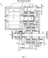
- the present invention relates generally to vehicular transaxle. More particularly, the present invention relates to a vehicular transaxle that is capable of receiving input power from a source of stored electrical energy. Specifically, the present invention relates to a four-speed transaxle that utilizes four planetary gear sets that is operatively connected to an electric motor and four electric caliper brake systems as well as one stage gears that is used to transmit power to differential assembly.
- a low emission vehicle is an electric vehicle
- the first electric powered vehicles employed power trains that received power from a source of stored electrical energy, such as a battery.
- power trains used for electric vehicles are primarily single-speed transaxles, i.e., pure reduction stages having an output speed that is reduced in comparison to an input speed.
- the electric drive must cover the entire rotational speed range, which significantly reduces its overall efficiency.
- the realizable speed range is rather narrow.
- two-speed transaxles may include an input shaft having two driving gears. Speed selection is achieved by sliding a synchronizer sleeve between two positions on an intermediate shaft assembly. A drive pinion of a final drive gear set may be part of the intermediate shaft assembly. A final drive output gear is attached to a bevel and side gear differential assembly that distributes output torque to left and right wheels of an electric vehicle. If such a two-speed transaxle is used, the electric drive trains can be of smaller design, which results in a clear cost benefit.
- the very configuration of the transmission with a sliding synchronizer sleeve causes a drop in traction force during shifting. However, for electric vehicles such a drop in traction force means a substantial sacrifice of comfort, which is not acceptable to the driver.
- CN205930269 U discloses a four-speed electric power system, including a motor which is connected with an input planetary mechanism and a middle planetary mechanism, input planetary mechanism, middle planetary mechanism and a double row planetary mechanism all are connected with a planet carrier, input planetary mechanism is connected with II shift brake disk, double row planetary mechanism is connected with III shift brake disk and IV shift brake disk, middle planetary mechanism is connected with a one way clutch and I shift brake disk, one way clutch's outer race and housing are connected, and the planetary carrier outputs power to an output gear group, which in turn is connected to the differential.
- the regulatable clutch system is designed as an electric caliper brake system with a dry brake disc having at least one pair pad plates and two pairs of independent screw-nut.
- a four-speed transaxle embodying the concepts of the present invention utilizes an input means to receive power from the electric motor and a power output means to deliver power to drive the vehicle.
- the electric motor is connected to energy storage devices, such as batteries, so that the energy storage devices can accept power from, and supply power to, the electric motor.
- a control unit regulates power flow between the energy storage devices and the electric motor.
- an electric four-speed transaxle for a vehicle comprising an electric motor; an input member for receiving power from an electric motor rotor; four planetary gear sets; the four planetary gear sets comprise a first planetary gear set, a second planetary gear set, a third planetary gear set and a fourth planetary gear set; each planetary gear set utilizes a sun gear, a ring gear, a carrier and a plurality of planet gears; a plurality of planet gears is rotatably mounted on the carrier; the sun gear and ring gear in each planetary gear set meshingly engages plurality of planet gears; the electric motor is successively coaxially aligned with the four planetary gear sets; the input member successively connected to a first sun gear in the first planetary gear set and a second sun gear in second planetary gear set; one stage gear; the stage gear comprises
- the first planetary gear set has a first inner gear member 18, which may generally be designated as a first ring gear 18, which circumscribes a first outer gear member 15, generally designated as the first sun gear 15.
- a plurality of first planet gear members 16 is rotatably mounted on a first carrier 17 such that each first planet gear 16 meshingly engages both the first ring gear 18 and the first sun gear 15.
- the first ring gear 18 has both the internal and external teeth.
- the first shift gear system comprises a first shift gear 19 which meshingly engages the external gear teeth of the first ring gear 18 and a first shift gear shaft 20 which is fixedly secured to a first dry disc 21.
- the first shift gear 19 is fixedly secured to the other end of the first shift gear shaft 20.
- the second planetary gear set has a second inner gear member 25, which may generally be designated as a second ring gear 25, which circumscribes a second outer gear member 23, generally designated as the second sun gear 23.
- a plurality of second planet gear members 24 is rotatably mounted on a second carrier 27 such that each second planet gear 24 meshingly engages both the second ring gear 25 and the second sun gear 23.
- the second ring gear 25 has both the internal and external teeth 26.
- the second shift gear system comprises a second shift gear 28 which meshingly engages the external gear teeth 26 of the second ring gear 25 and a second shift gear shaft 29 which is fixedly secured to a second dry disc 30.
- the second shift gear 28 is fixedly secured to the other end of the second shift gear shaft 29.
- a third planetary gear set has a third inner gear member 37, which may generally be designated as a third ring gear 37, which circumscribes a third outer gear member 34, generally designated as a third sun gear 34.
- a plurality of third planet gear members 35 is rotatably mounted on a third carrier 36 such that each third planet gear 35 meshingly engages both the third ring gear 37 and the third sun gear 34.
- the third sun gear 34 in the third planetary gear set is connected with a first connecting gear 40 by a third sun gear shaft.
- the third shift gear system comprises a third shift gear 41 which meshingly engages the first connecting gear 40 and a third shift gear shaft 42 which is fixedly secured to a third dry disc 43.
- the third shift gear 41 is fixedly secured to the other end of the third shift gear shaft 42.
- a fourth planetary gear set has a fourth inner gear member 39, which may generally be designated as a fourth ring gear 39, which circumscribes a fourth outer gear member 45, generally designated as a fourth sun gear 45.
- a plurality of fourth planet gear members is rotatably mounted on a fourth carrier 38 such that each fourth planet gear 46 meshingly engages both the fourth ring gear 39 and the fourth sun gear 45.
- a second connecting gear 47 has an outer tooth structure, which is mounted on the outer circumference of the whole ring formed by the third ring gear 37 and the fourth ring gear 39. There are two symmetrically arranged a fourth shift gear systems.
- the fourth shift gear system comprises a fourth shift gear 48 which meshingly engages the second connecting gear 47 and a fourth shift gear shaft 49 which is fixedly secured to a fourth dry disc 50.
- the fourth shift gear 48 is fixedly secured to the other end of the fourth shift gear shaft 49.
- a driving gear 32 is fixed for rotation with the second carrier 27 providing power from the first and second planetary gear sets.
- a driven gear 33 is fixed for rotation with the third carrier 36 and the fourth sun gear 45 provided power to the third and fourth planetary gear sets.
- the driving gear 32 meshingly engages the driven gear 33.
- the third sun gear 34 and the fourth sun gear 45 are hollow allowing the right shaft 54 to pass through them center from the differential assembly 52 to the right wheel of the electric vehicle.
- the third carrier 36 is fixedly connected with the fourth sun gear 45.
- the fourth carrier 38 is fixedly connected to a differential carrier of the differential assembly 52 that distributes output torque to left and right wheels of an electric vehicle by the left shaft 53 and the right shaft 54.
- the first electric caliper brake system 22, the left pad plate 22e and the right pad plate 22g are pressed against the first dry disc 21 by the right pair of screw-nut and the left pair of screw-nut inside the floating caliper 22n, respectively, driven by the shifting driven gear 22k power from the shifting driving gear 22c by using the shifting motor 22a.
- the first electric caliper brake system 22 and the first dry disc 21 are mounted on outside of the transaxle housing.
- a plurality of speed teeth is uniformly processed on the circumferential surface of the first dry disc 21.
- the shifting motor 22a and the shifting reducer 22b are fixedly secured to outside surface of the casing 22d.
- the casing 22d is fixedly secured to outside surface the transaxle housing by two guide bolts.
- the floating caliper 22n mounted on the casing 22d can move along the two guide bolts.
- the ends of the left screw 22l and the right screw 22j are fixed in an inner hole of the shifting driven gear 22k.
- the end of the left nut 22m is contacted with an inner wall of the floating caliper 22n.
- the end of the right nut 22h is contacted with the wall of the left pad plate 22e.
- the wall of the right pad plate 22g is contacted with the other inner wall of the floating caliper 22n.
- a second electric caliper brake system 31 is floating caliper architecture, comprises shifting motor 31a, shifting reducer 31b, a casing 31d, shifting driving gear 31c, shifting driven gear 31k, a left nut 31m, a left screw 311, a right nut 31h, a right screw 31j, a left pad plate 31e, a right pad plate 31g, a speed sensor 31f for watching state of the second dry disc 30 as well as a floating caliper 31n.
- the second electric caliper brake system 31, the left pad plate 31e and the right pad plate 31g are pressed against the second dry disc 30 by the right pair of screw-nut and the left pair of screw-nut inside the floating caliper 31n, respectively, driven by the shifting driven gear 31k power from the shifting driving gear 31c by using the shifting motor 31a.
- the second electric caliper brake system 31 and the second dry disc 30 are mounted on outside of a transaxle housing.
- a plurality of speed teeth is uniformly processed on the circumferential surface of the second dry disc 30.
- the third electric caliper brake system 44, the left pad plate 44e and the right pad plate 44g are pressed against the third dry disc 43 by the right pair of screw-nut and the left pair of screw-nut inside the floating caliper 44n, respectively, driven by the shifting driven gear 44k power from the shifting driving gear 44c by using the shifting motor 44a.
- the third electric caliper brake system 44 and the third dry disc 43 are mounted on outside of the transaxle housing.
- a plurality of speed teeth is uniformly processed on the circumferential surface of the third dry disc 43.
- a fourth electric caliper brake system 51 is floating caliper architecture, comprises shifting motor 51a, shifting reducer 51b, a casing 51d, shifting driving gear 51c, shifting driven gear 51k, a left nut 51m, a left screw 511, a right nut 51h, a right screw 51j, a left pad plate 51e, a right pad plate 51g, a speed sensor 51f for watching state of the fourth dry disc 50 as well as a floating caliper 51n.
- the shifting motor 51a and the shifting reducer 51b are fixedly secured to outside surface of the casing 51d.
- the casing 51d is fixedly secured to outside surface the transaxle housing by two guide bolts.
- the floating caliper 51n mounted on the casing 51d can move along the two guide bolts.
- the ends of the left screw 511 and the right screw 51j are fixed in an inner hole of the shifting driven gear 51k.
- the end of the left nut 51m is contacted with an inner wall of the floating caliper 51n.
- the end of the right nut 51h is contacted with the wall of the left pad plate 51e.
- the wall of the right pad plate 51g is contacted with the other inner wall of the floating caliper 51n.
- First speed ratio results when the first electric caliper brake system 22 and the third electric caliper brake system 44 are disengaged and the second electric caliper brake system 31 and the fourth electric brake system 51 are engaged.
- the clearance is kept up between the left and right pad plates 22e, 22g and the first dry disc 21.
- the clearance is also kept up between the left and right pad plates 44e, 44g and the third dry disc 43.
- There are setting pressure force from the shifting motor 31a is used to push the left and right pairs of screw-nut to move the left and right pad plates 31e, 31g braking the second dry disc 30.
- There are also setting pressure force from the shifting motor 51a is used to push the left and right pairs of screw-nut to move the left and right pad plates 51e, 51g braking the fourth dry disc 50.
- the second shift gear shaft 29 which is fixedly secured to the second dry disc 30, and the second shift gear 28 is fixedly secured to the second shift gear shaft 29 and meshingly engages the outer gear teeth 26 of the second ring gear 25, so the second ring gear 25 is locked which provides the torque reaction point for the second planetary gear set.
- the fourth shift gear shaft 49 which is fixedly secured to the fourth dry disc 50, and the fourth shift gear 48 is fixedly secured to the fourth shift gear shaft 49 and meshingly engages the fourth connecting gear 47, so the fourth ring gear 39 is locked which provides the torque reaction point for the fourth planetary gear set.
- the first ring gear 18 and the third sun gear 34 drive the first dry disc 21 and the third dry disc 43 to freely rotatably around the first shift gear shaft 20 and the third shift gear shaft 42 through the first shift gear 19 and the third shift gear 41 without friction, respectively.
- the torque delivery path for the first speed ratio for the four-speed transaxle 10 includes the second sun gear 23, which is driven by the electric motor through the input shaft 14, the plurality of second planet gears 24, the second ring gear 25 locked which provides the torque reaction point for the second planetary gear set, the second carrier 27 transmits the torque from the input shaft 14 through the driving gear 32 and the driven gear 33 to the third carrier 36 and the fourth sun gear 45, the plurality of fourth planet gears 46, the fourth ring gear 39 locked which provides the torque reaction point for the fourth planetary gear set, the fourth carrier 38 transmits the torque from the second carrier 27 to the differential assembly 52 through the differential carrier, the differential assembly 52 transmits the torque to the left side shaft 53 and the right side shaft 54.
- Second speed ratio results when the second electric caliper brake system 31 and the third electric caliper brake system 44 are disengaged and the first electric caliper brake system 22 and the fourth electric brake system 51 are engaged.
- the clearance is kept up between the left and right pad plates 31e, 31g and the second dry disc 30.
- the clearance is also kept up between the left and right pad plates 44e, 44g and the third dry disc 43.
- There are setting pressure force from the shifting motor 22a is used to push the left and right pairs of screw-nut to move the left and right pad plates 22e, 22g braking the first dry disc 21.
- There are also setting pressure force from the shifting motor 51a is used to push the left and right pairs of screw-nut to move the left and right pad plates 51e, 51g braking the fourth dry disc 50.
- first shift gear shaft 20 which is fixedly secured to the first dry disc 21, and the first shift gear 19 is fixedly secured to the first shift gear shaft 20 and meshingly engages the outer gear teeth of the first ring gear 18, so the first ring gear 18 is locked which provides the torque reaction point for the first planetary gear set.
- fourth shift gear shaft 49 which is fixedly secured to the fourth dry disc 50, and the fourth shift gear 48 is fixedly secured to the fourth shift gear shaft 49 and meshingly engages the fourth connecting gear 47, so the fourth ring gear 39 is locked which provides the torque reaction point for the fourth planetary gear set.
- the second ring gear 25 and the third sun gear 34 drive the second dry disc 30 and the third dry disc 43 to freely rotatably around the second shift gear shaft 29 and the third shift gear shaft 42 through the second shift gear 28 and the third shift gear 41 without friction, respectively.
- the torque delivery path for the second speed ratio for the four-speed transaxle 10 includes the first sun gear 15 and the second sun gear 23, which are driven by the electric motor through the input shaft 14, the plurality of first and second planet gears 16 and 24, the first carrier 17 and the second ring gear 25, the first ring gear 18 locked which provides the torque reaction point for the first planetary gear set, the second carrier 27 transmits the torque from the input shaft 14 through the driving gear 32 and the driven gear 33 to the third carrier 36 and the fourth sun gear 45, the plurality of fourth planet gears 46, the fourth ring gear 39 locked which provides the torque reaction point for the fourth planetary gear set, the fourth carrier 38 transmits the torque from the second carrier 27 to the differential assembly 52 through the differential carrier, the differential assembly 52 transmits the torque to the left side shaft 53 and the right side shaft 54.
- Third speed ratio results when the first electric caliper brake system 22 and the fourth electric caliper brake system 51 are disengaged and the second electric caliper brake system 31 and the third electric brake system 44 are engaged.
- the clearance is kept up between the left and right pad plates 22e, 22g and the first dry disc 21.
- the clearance is also kept up between the left and right pad plates 51e, 51g and the fourth dry disc 50.
- There are setting pressure force from the shifting motor 31a is used to push the left and right pairs of screw-nut to move the left and right pad plates 31e, 31g braking the second dry disc 30.
- There are also setting pressure force from the shifting motor 44a is used to push the left and right pairs of screw-nut to move the left and right pad plates 44e, 44g braking the third dry disc 43.
- the second shift gear shaft 29 which is fixedly secured to the second dry disc 30, and the second shift gear 28 is fixedly secured to the second shift gear shaft 29 and meshingly engages the outer gear teeth 26 of the second ring gear 25, so the second ring gear 25 is locked which provides the torque reaction point for the second planetary gear set.
- the third shift gear shaft 42 which is fixedly secured to the third dry disc 43, and the third shift gear 41 is fixedly secured to the third shift gear shaft 42 and meshingly engages the third connecting gear 40, so the third sun gear 34 is locked which provides the torque reaction point for the third planetary gear set.
- the first ring gear 18 and the fourth ring gear 39 drive the first dry disc 21 and the fourth dry disc 50 to freely rotatably around the first shift gear shaft 20 and the fourth shift gear shaft 49 through the first shift gear 19 and the fourth shift gear 48 without friction, respectively.
- the torque delivery path for the third speed ratio for the four-speed transaxle 10 includes the second sun gear 23, which is driven by the electric motor through the input shaft 14, the plurality of second planet gears 24, the second ring gear 25 locked which provides the torque reaction point for the second planetary gear set, the second carrier 27 transmits the torque from the input shaft 14 through the driving gear 32 and the driven gear 33 to the third carrier 36 and the fourth sun gear 45, the plurality of third and fourth planet gears 35 and 46, the third and fourth ring gear 39 and 39, the third sun gear 34 locked which provides the torque reaction point for the third planetary gear set, the fourth carrier 38 transmits the torque from the second carrier 27 to the differential assembly 52 through the differential carrier, the differential assembly 52 transmits the torque to the left side shaft 53 and the right side shaft 54.
- Fourth speed ratio results when the second electric caliper brake system 31 and the fourth electric caliper brake system 51 are disengaged and the first electric caliper brake system 22 and the third electric brake system 44 are engaged.
- the clearance is kept up between the left and right pad plates 31e, 31g and the second dry disc 30.
- the clearance is also kept up between the left and right pad plates 51e, 51g and the fourth dry disc 50.
- There are setting pressure force from the shifting motor 22a is used to push the left and right pairs of screw-nut to move the left and right pad plates 22e, 22g braking the first dry disc 21.
- There are also setting pressure force from the shifting motor 44a is used to push the left and right pairs of screw-nut to move the left and right pad plates 44e, 44g braking the third dry disc 43.
- first shift gear shaft 20 which is fixedly secured to the first dry disc 21, and the first shift gear 19 is fixedly secured to the first shift gear shaft 20 and meshingly engages the outer gear teeth of the first ring gear 18, so the first ring gear 18 is locked which provides the torque reaction point for the first planetary gear set.
- third shift gear shaft 42 which is fixedly secured to the third dry disc 43, and the third shift gear 41 is fixedly secured to the third shift gear shaft 42 and meshingly engages the third connecting gear 40, so the third sun gear 34 is locked which provides the torque reaction point for the third planetary gear set.
- the second ring gear 25 and the fourth ring gear 39 drive the second dry disc 30 and the fourth dry disc 50 to freely rotatably around the second shift gear shaft 29 and the fourth shift gear shaft 49 through the second shift gear 28 and the fourth shift gear 48 without friction, respectively.
- the torque delivery path for the second speed ratio for the four-speed transaxle 10 includes the first sun gear 15 and the second sun gear 23, which are driven by the electric motor through the input shaft 14, the plurality of first and second planet gears 16 and 24, the first carrier 17 and the second ring gear 25, the first ring gear 18 locked which provides the torque reaction point for the first planetary gear set, the second carrier 27 transmits the torque from the input shaft 14 through the driving gear 32 and the driven gear 33 to the third carrier 36 and the fourth sun gear 45, the plurality of third and fourth planet gears 35 and 46, the third and fourth ring gear 39 and 39, the third sun gear 34 locked which provides the torque reaction point for the third planetary gear set, the fourth carrier 38 transmits the torque from the second carrier 27 to the differential assembly 52 through the differential carrier, the differential assembly 52 transmits the torque to the left side shaft 53 and the right side shaft 54.
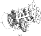
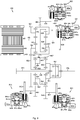
- FIGS. 2A and 2B This highly preferred form of a four-speed transaxle embodying the concepts of the present invention, is designated generally by the numeral 110 on the FIGS. 2A and 2B .
- the four-speed transaxle 110 utilizes four planetary gear sets.
- the electric motor is coaxially aligned with four planetary gear sets.
- the four-speed transaxle 110 has an input member 114 that may be in the nature of shaft which may be directly driven by an electric motor rotor 111.
- the input shaft 114 is successively connected to a first sun gear 115 in a first planetary gear set and a second sun gear 123 in a second planetary gear set in the four-speed transaxle 110.
- a differential assembly 152 comprises a differential carrier, which is rotatingly driveable around its axis, as well as a left shaft 153 and a right shaft 154.
- the first planetary gear set has a first inner gear member 118, which may generally be designated as the first ring gear 118, which circumscribes a first outer gear member 115, generally designated as the first sun gear 115.
- a plurality of first planet gear members 116 is rotatably mounted on a first carrier 117 such that each first planet gear 116 meshingly engages both the first ring gear 118 and the first sun gear 115.
- the first ring gear 118 has both the internal and external teeth. There are two symmetrically arranged first shift gear systems.
- the first shift gear system comprises a first shift gear 119 which meshingly engages the outer gear teeth of the first ring gear 118 and a first shift gear shaft 120 which is fixedly secured to a first dry disc 121.
- the first shift gear 119 is fixedly secured to the other end of the first shift gear shaft 120.
- the second planetary gear set has a second inner gear member 125, which may generally be designated as a second ring gear 125, which circumscribes a second outer gear member 123, generally designated as the second sun gear 123.
- a plurality of second planet gear members 124 is rotatably mounted on a second carrier 127 such that each second planet gear 124 meshingly engages both the second ring gear 125 and the second sun gear 123.
- the second ring gear 125 has both the internal and external teeth 126. There are two symmetrically arranged a second shift gear systems.
- the third planetary gear set has a third inner gear member 145, which may generally be designated as the third ring gear 145, which circumscribes a third outer gear member 134, generally designated as the third sun gear 134.
- a plurality of third planet gear members 135 is rotatably mounted on a third carrier 146 such that each third planet gear 135 meshingly engages both the third ring gear 145 and the third sun gear 134.
- a connecting gear 139 has an outer tooth structure, which is mounted on the outer circumference of the whole ring formed by the third ring gear 145 and the fourth ring gear 138.
- the fourth shift gear system comprises a fourth shift gear 148 which meshingly engages the connecting gear 139 and a fourth shift gear shaft 149 which is fixedly secured to a fourth dry disc 150.
- the fourth shift gear 148 is fixedly secured to the other end of the fourth shift gear shaft 149.
- the fourth sun gear 140 is fixedly secured to a third dry disc 143 through a third shift gear shaft 142.
- the first carrier 117 is fixedly connected to the second ring gear 125.
- a driving gear 132 is fixed for rotation with the third carrier 132 providing power from the third and fourth planetary gear sets.
- the second carrier 127 is successively connected to the third sun gear 134 and the fourth carrier 140 through a middle shaft 147.
- the driving gear 132 meshingly engages a driven gear 133.
- the driven gear 133 is fixed for rotation with the differential carrier of the differential assembly 152.
- the differential assembly 152 distributes output torque from the electric motor to left and right wheels of an electric vehicle by the left shaft 153 and the right shaft 154.
- a first electric caliper brake system 122 is floating caliper architecture, comprises a shifting motor 122a, a shifting reducer 122b, a casing 122d, a shifting driving gear 122c, a shifting driven gear 122k, a left nut 122m, a left screw 1221, a right nut 122h, a right screw 122j, a left pad plate 122e, a right pad plate 122g, a speed sensor 122f for watching state of the first dry disc 121 as well as a floating caliper 122n.
- the first electric caliper brake system 122, the left pad plate 122e and the right pad plate 122g are pressed against the first dry disc 121 by the right pair of screw-nut and the left pair of screw-nut inside the floating caliper 122n, respectively, driven by the shifting driven gear 122k power from the shifting driving gear 122c by using the shifting motor 122a.
- the first electric caliper brake system 122 and the first dry disc121 are mounted on outside of the transaxle housing. A plurality of speed teeth is uniformly processed on the circumferential surface of the first dry disc 121.
- the shifting motor 122a and the shifting reducer 122b are fixedly secured to outside surface of the casing 122d.
- the casing 122d is fixedly secured to outside surface the transaxle housing by two guide bolts.
- the floating caliper 122n mounted on the casing 122d can move along the two guide bolts.
- the ends of the left screw 1221 and the right screw 122j are fixed in an inner hole of the shifting driven gear 122k.
- the end of the left nut 122m is contacted with an inner wall of the floating caliper 122n.
- the end of the right nut 122h is contacted with the wall of the left pad plate 122e.
- the wall of the right pad plate 122g is contacted with the other inner wall of the floating caliper 122n.
- the speed sensor 122f is mounted on the top of the floating caliper 122n.
- a second electric caliper brake system 131 is floating caliper architecture, comprises a shifting motor 131a, a shifting reducer 131b, a casing 131d, a shifting driving gear 131c, a shifting driven gear 131k, a left nut 131m, a left screw 1311, a right nut 131h, a right screw 131j, a left pad plate 131e, a right pad plate 131g, a speed sensor 131f for watching state of the second dry disc 130 as well as a floating caliper 131n.
- the second electric caliper brake system 131, the left pad plate 131e and the right pad plate 131g are pressed against the second dry disc 130 by the right pair of screw-nut and the left pair of screw-nut inside the floating caliper 131n, respectively, driven by the shifting driven gear 131k power from the shifting driving gear 131c by using the shifting motor 131a.
- the second electric caliper brake system 131 and the second dry disc 130 are mounted on outside of the transaxle housing. A plurality of speed teeth is uniformly processed on the circumferential surface of the second dry disc 130.
- the shifting motor 131a and the shifting reducer 131b are fixedly secured to outside surface of the casing 131d.
- the casing 131d is fixedly secured to outside surface the transaxle housing by two guide bolts.
- the floating caliper 131n mounted on the casing 131d can move along the two guide bolts.
- the ends of the left screw 1311 and the right screw 131j are fixed in an inner hole of the shifting driven gear 131k.
- the end of the left nut 131m is contacted with an inner wall of the floating caliper 131n.
- the end of the right nut 131h is contacted with the wall of the left pad plate 131e.
- the wall of the right pad plate 131g is contacted with the other inner wall of the floating caliper 131n.
- the speed sensor 131f is mounted on the top of the floating caliper 131n.
- a third electric caliper brake system 144 is floating caliper architecture, comprises a shifting motor 144a, a shifting reducer 144b, a casing 144d, a shifting driving gear 144c, a shifting driven gear 144k, a left nut 144m, a left screw 1441, a right nut 144h, a right screw 144j, a left pad plate 144e, a right pad plate 144g, a speed sensor 144f for watching state of the third dry disc 143 as well as a floating caliper 144n.
- the third electric caliper brake system 144, the left pad plate 144e and the right pad plate 144g are pressed against the third dry disc 143 by the right pair of screw-nut and the left pair of screw-nut inside the floating caliper 144n, respectively, driven by the shifting driven gear 144k power from the shifting driving gear 144c by using the shifting motor 144a.
- the third electric caliper brake system 144 and the third dry disc 143 are mounted on outside of the transaxle housing. A plurality of speed teeth is uniformly processed on the circumferential surface of the third dry disc 143.
- the shifting motor 144a and the shifting reducer 144b are fixedly secured to outside surface of the casing 144d.
- the casing 144d is fixedly secured to outside surface the transaxle housing by two guide bolts.
- the floating caliper 144n mounted on the casing 144d can move along the two guide bolts.
- the ends of the left screw 1441 and the right screw 144j are fixed in an inner hole of the shifting driven gear 144k.
- the end of the left nut 144m is contacted with an inner wall of the floating caliper 144n.
- the end of the right nut 144h is contacted with the wall of the left pad plate 144e.
- the wall of the right pad plate 144g is contacted with the other inner wall of the floating caliper 144n.
- the speed sensor 144f is mounted on the top of the floating caliper 144n.
- the fourth electric caliper brake system 151 is floating caliper architecture, comprises shifting motor 151a, shifting reducer 151b, a casing 151d, shifting driving gear 151c, shifting driven gear 151k, a left nut 151m, a left screw 1511, a right nut 151h, a right screw 151j, a left pad plate 151e, a right pad plate 151g, a speed sensor 151f for watching state of the fourth dry disc 150 as well as a floating caliper 151n.
- the fourth electric caliper brake system 151, the left pad plate 151e and the right pad plate 151g are pressed against the fourth dry disc 150 by the right pair of screw-nut and the left pair of screw-nut inside the floating caliper 151n, respectively, driven by the shifting driven gear 151k power from the shifting driving gear 151c by using the shifting motor 151a.
- the fourth electric caliper brake system 151 and the fourth dry disc 150 are mounted on outside of the transaxle housing.
- a plurality of speed teeth is uniformly processed on the circumferential surface of the fourth dry disc 150. There is a clearance about 2mm between the speed sensor 151f and the circumferential surface of the fourth dry disc 150.
- the shifting motor 151a and the shifting reducer 151b are fixedly secured to outside surface of the casing 151d.
- the casing 151d is fixedly secured to outside surface the transaxle housing by two guide bolts.
- the floating caliper 151n mounted on the casing 151d can move along the two guide bolts.
- the ends of the left screw 1511 and the right screw 151j are fixed in an inner hole of the shifting driven gear 151k.
- the end of the left nut 151m is contacted with an inner wall of the floating caliper 151n.
- the end of the right nut 151h is contacted with the wall of the left pad plate 151e.
- the wall of the right pad plate 151g is contacted with the other inner wall of the floating caliper 151n.
- the speed sensor 151f is mounted on the top of the floating caliper 151n.
- the control device determines what is required and then manipulates the selectively operated components of the four-speed transaxle 110 appropriately to respond to the operator demand.
- Four speed ratios are provided by changing the states of four electric caliper brake systems.
- the power supplied by the four-speed transaxle 110 is predicated solely by the power delivered to the four-speed transaxle 110 from the electric motor.
- First speed ratio results when the first electric caliper brake system 122 and the third electric caliper brake system 144 are disengaged and the second electric caliper brake system 131 and the fourth electric brake system 151 are engaged. And then, the second ring gear 125 and the third ring gear 145 are locked.
- Second speed ratio results when the second electric caliper brake system 131 and the third electric caliper brake system 144 are disengaged and the first electric caliper brake system 122 and the fourth electric brake system 151 are engaged. And then, the first ring gear 118 and the third ring gear 145 are locked.
- Third speed ratio results when the first electric caliper brake system 122 and the fourth electric caliper brake system 151 are disengaged and the second electric caliper brake system 131 and the third electric brake system 144 are engaged. And then, the second ring gear 125 and the fourth sun gear 140 are locked.
- Fourth speed ratio results when the second electric caliper brake system 131 and the fourth electric caliper brake system 151 are disengaged and the first electric caliper brake system 122 and the third electric brake system 144 are engaged. And then, the first ring gear 118 and the fourth sun gear 140 are locked.
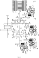
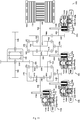
- the four-speed transaxle 210 utilizes four planetary gear sets.
- the electric motor is coaxially aligned with the first and second planetary gear sets.
- a differential assembly 252 is coaxially aligned with the third and fourth planetary gear sets.
- the four-speed transaxle 210 has an input member 214 that may be in the nature of shaft which may be directly driven by an electric motor rotor 211.
- the input shaft 214 is connected to a first sun gear 215 in a first planetary gear set in the four-speed transaxle 210.
- the first shift gear system comprises a first shift gear 219 which meshingly engages the outer gear teeth of the first connecting gear 218 and a first shift gear shaft 220 which is fixedly secured to a first dry disc 221.
- the first shift gear 219 is fixedly secured to the other end of the first shift gear shaft 220.
- the second planetary gear set has a second inner gear member 224, which may generally be designated as a second ring gear 224, which circumscribes a second outer gear member 226, generally designated as a second sun gear 226.
- a plurality of second planet gear members 225 is rotatably mounted on a second carrier 227 such that each second planet gear 225 meshingly engages both the second ring gear 224 and the second sun gear 226.
- a second connecting gear 232 is mounted on the second carrier gear 227.
- the second shift gear system comprises a second shift gear 228 which meshingly engages the outer gear teeth of the second connecting gear 232 and a second shift gear shaft 229 which is fixedly secured to a second dry disc 230.
- the second shift gear 228 is fixedly secured to the other end of the second shift gear shaft 229.
- the third planetary gear set has a third inner gear member 239, which may generally be designated as a third ring gear 239, which circumscribes a third outer gear member 235, generally designated as a third sun gear 235.
- a plurality of third planet gear members 236 is rotatably mounted on a third carrier 237 such that each third planet gear 236 meshingly engages both the third ring gear 239 and the third sun gear 235.
- a third connecting gear 232 is mounted on the third carrier 237.
- the third shift gear system comprises a third shift gear 241 which meshingly engages the outer gear teeth of the third connecting gear 238 and a third shift gear shaft 242 which is fixedly secured to a third dry disc 243.
- the third shift gear 241 is fixedly secured to the other end of the third shift gear shaft 242.
- the third ring gear 239 has both the internal and external teeth.
- the fourth shift gear system comprises a fourth shift gear 248 which meshingly engages the outer gear teeth of the third ring gear 239 and a fourth shift gear shaft 249 which is fixedly secured to a fourth dry disc 250.
- the fourth shift gear 248 is fixedly secured to the other end of the fourth shift gear shaft 249.
- the fourth planetary gear set has a fourth inner gear member 247, which may generally be designated as the fourth ring gear 247, which circumscribes a fourth outer gear member 240, generally designated as the fourth sun gear 240.
- a plurality of fourth planet gear members 246 is rotatably mounted on a fourth carrier 245 such that each fourth planet gear 246 meshingly engages both the fourth ring gear 247 and the fourth sun gear 240.
- the first carrier 217 is fixedly connected to the second ring gear 224.
- a driving gear 233 is successively fixed for rotation with the second sun gear 226 and the first ring gear 223 providing power from the first and second planetary gear sets.
- a driven gear 234 is successively fixed for rotation with the third sun gear 235 and the fourth sun gear 240 providing power from the third and fourth planetary gear sets.
- the fourth carrier 245 is fixedly connected to the third ring gear 239.
- the driving gear 233 meshingly engages the driven gear 234.
- the first electric caliper brake system 222, the left pad plate 222e and the right pad plate 222g are pressed against the first dry disc 221 by the right pair of screw-nut and the left pair of screw-nut inside the floating caliper 222n, respectively, driven by the shifting driven gear 222k power from the shifting driving gear 222c by using the shifting motor 222a.
- the first electric caliper brake system 222 and the first dry disc 221 are mounted on outside of the transaxle housing. A plurality of speed teeth is uniformly processed on the circumferential surface of the first dry disc 221.
- the control device determines what is required and then manipulates the selectively operated components of the four-speed transaxle 210 appropriately to respond to the operator demand.
- Four speed ratios are provided by changing the states of four electric caliper brake systems.
- the power supplied by the four-speed transaxle 210 is predicated solely by the power delivered to the four-speed transaxle 210 from the electric motor.
- the fourth shift gear system comprises a fourth shift gear 348 which meshingly engages the outer gear teeth of the fourth ring gear 346 and a fourth shift gear shaft 349 which is fixedly secured to a third dry disc 350.
- the fourth shift gear 348 is fixedly secured to the other end of the fourth shift gear shaft 349.
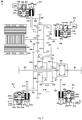
- the second planetary gear set has a second outer gear member 428, generally designated as a second sun gear 428.
- a plurality of second planet gear members 426 and idle gears 427 is rotatably mounted on the first carrier 424 such that each idle gear 427 meshingly engages both the second sun gear 428 and each second planet gear 426.
- the first planet gear 416 is coaxially installed with the second planet gear 426.
- the second sun gear 428 is fixedly secured to a second dry disc 430 through a second shift gear shaft 429.
- the third planetary gear set has a third inner gear member 438, which may generally be designated as a third ring gear 438, which circumscribes a third outer gear member 445, generally designated as a third sun gear 445.
- a plurality of third planet gear members 442 is rotatably mounted on a third carrier 433 such that each third planet gear 432 meshingly engages both the third ring gear 438 and the third sun gear 445.
- a first connecting gear 447 is fixedly secured to the third sun gear 445 through a shaft 446.
- the fourth planetary gear set has a fourth inner gear member 439, which may generally be designated as a fourth ring gear 439, which circumscribes a fourth outer gear member 435, generally designated as a fourth sun gear 435.
- a plurality of fourth planet gear members 437 is rotatably mounted on a fourth carrier 434 such that each fourth planet gear 437 meshingly engages both the fourth ring gear 439 and the fourth sun gear 435.
- a second connecting gear 440 has an outer tooth structure, which is mounted on the outer circumference of the whole ring formed by the third ring gear 438 and the fourth ring gear 439. There are two symmetrically arranged a third shift gear systems.
- the first carrier 424 is fixedly connected to a driving gear 423 through a connecting member 417.
- a driven gear 425 is successively connected to the third carrier 433 and the fourth sun gear 435.
- the driving gear 423 meshingly engages the driven gear 425.
- the fourth carrier 434 is fixed for rotation with the differential carrier of the differential assembly 452.
- the differential assembly 452 distributes output torque from the electric motor to left and right wheels of an electric vehicle by a left shaft 453 and a right shaft 454.
- the first electric caliper brake system 422, the left pad plate 422e and the right pad plate 422g are pressed against the first dry disc 421 by the right pair of screw-nut and the left pair of screw-nut inside the floating caliper 422n, respectively, driven by the shifting driven gear 422k power from the shifting driving gear 422c by using the shifting motor 422a.
- the first electric caliper brake system 422 and the first dry disc 421 are mounted on outside of the transaxle housing. A plurality of speed teeth is uniformly processed on the circumferential surface of the first dry disc 421.
- the shifting motor 422a and the shifting reducer 422b are fixedly secured to outside surface of the casing 422d.
- the casing 422d is fixedly secured to outside surface the transaxle housing by two guide bolts.
- the floating caliper 422n mounted on the casing 422d can move along the two guide bolts.
- the ends of the left screw 422l and the right screw 422j are fixed in an inner hole of the shifting driven gear 422k.
- the second electric caliper brake system 431, the left pad plate 431e and the right pad plate 431g are pressed against the second dry disc 430 by the right pair of screw-nut and the left pair of screw-nut inside the floating caliper 431n, respectively, driven by the shifting driven gear 431k power from the shifting driving gear 431c by using the shifting motor 431a.
- the second electric caliper brake system 431 and the second dry disc 430 are mounted on outside of the transaxle housing. A plurality of speed teeth is uniformly processed on the circumferential surface of the second dry disc 430.
- the end of the left nut 431m is contacted with an inner wall of the floating caliper 431n.
- the end of the right nut 431h is contacted with the wall of the left pad plate 431e.
- the wall of the right pad plate 431g is contacted with the other inner wall of the floating caliper 431n.
- the speed sensor 431f is mounted on the top of the floating caliper 431n.
- the third electric caliper brake system 444, the left pad plate 444e and the right pad plate 444g are pressed against the third dry disc 443 by the right pair of screw-nut and the left pair of screw-nut inside the floating caliper 444n, respectively, driven by the shifting driven gear 444k power from the shifting driving gear 444c by using the shifting motor 444a.
- the third electric caliper brake system 444 and the third dry disc 443 are mounted on outside of the transaxle housing. A plurality of speed teeth is uniformly processed on the circumferential surface of the third dry disc 443.
- the shifting motor 444a and the shifting reducer 444b are fixedly secured to outside surface of the casing 444d.
- the casing 444d is fixedly secured to outside surface the transaxle housing by two guide bolts.
- the floating caliper 444n mounted on the casing 444d can move along the two guide bolts.
- the ends of the left screw 4441 and the right screw 444j are fixed in an inner hole of the shifting driven gear 444k.
- the end of the left nut 444m is contacted with an inner wall of the floating caliper 444n.
- the end of the right nut 444h is contacted with the wall of the left pad plate 444e.
- the wall of the right pad plate 444g is contacted with the other inner wall of the floating caliper 444n.
- the speed sensor 444f is mounted on the top of the floating caliper 444n.
- a fourth electric caliper brake system 451 is floating caliper architecture, comprises a shifting motor 451a, a shifting reducer 451b, a casing 451d, a shifting driving gear 451c, a shifting driven gear 451k, a left nut 451m, a left screw 4511, a right nut 451h, a right screw 451j, a left pad plate 451e, a right pad plate 451g, a speed sensor 451f for watching state of the fourth dry disc 450 as well as a floating caliper 451n.
- the fourth electric caliper brake system 451, the left pad plate 451e and the right pad plate 451g are pressed against the fourth dry disc 450 by the right pair of screw-nut and the left pair of screw-nut inside the floating caliper 451n, respectively, driven by the shifting driven gear 451k power from the shifting driving gear 451c by using the shifting motor 451a.
- the fourth electric caliper brake system 451 and the fourth dry disc 450 are mounted on outside of the transaxle housing.
- a plurality of speed teeth is uniformly processed on the circumferential surface of the fourth dry disc 450.
- the shifting motor 451a and the shifting reducer 451b are fixedly secured to outside surface of the casing 451d.
- the casing 451d is fixedly secured to outside surface the transaxle housing by two guide bolts.
- the floating caliper 451n mounted on the casing 451d can move along the two guide bolts.
- the ends of the left screw 4511 and the right screw 451j are fixed in an inner hole of the shifting driven gear 451k.
- the end of the left nut 451m is contacted with an inner wall of the floating caliper 451n.
- the end of the right nut 451h is contacted with the wall of the left pad plate 451e.
- the wall of the right pad plate 451g is contacted with the other inner wall of the floating caliper 451n.
- the speed sensor 451f is mounted on the top of the floating caliper 451n.
- the control device determines what is required and then manipulates the selectively operated components of the four-speed transaxle 410 appropriately to respond to the operator demand.
- Four speed ratios are provided by changing the states of four electric caliper brake systems.
- the power supplied by the four-speed transaxle 410 is predicated solely by the power delivered to the four-speed transaxle 410 from the electric motor.
- First speed ratio results when the second electric caliper brake system 431 and the fourth electric caliper brake system 451 are disengaged and the first electric caliper brake system 422 and the third electric brake system 444 are engaged. And then, the first ring gear 418 and the fourth ring gear 439 are locked.
- Second speed ratio results when the first electric caliper brake system 422 and the fourth electric caliper brake system 451 are disengaged and the second electric caliper brake system 431 and the third electric brake system 444 are engaged. And then, the second sun gear 428 and the fourth ring gear 439 are locked.
- Third speed ratio results when the second electric caliper brake system 431 and the third electric brake system 444 are disengaged and the first electric caliper brake system 422 and the fourth electric caliper brake system 451 are engaged. And then, the first ring gear 418 and the third sun gear 445 are locked.
- Fourth speed ratio results when the first electric caliper brake system 422 and the third electric brake system 444 are disengaged and the second electric caliper brake system 431 and the fourth electric caliper brake system 451 are engaged. And then, the second sun gear 428 and the third sun gear 445 are locked.
- This example is designated generally by the numeral 510 on the FIG. 6 . It is observed that the four-speed transaxle 510 utilizes four planetary gear sets. The electric motor is coaxially aligned with the four planetary gear sets. The four-speed transaxle 510 has an input member 514 that may be in the nature of shaft which may be directly driven by an electric motor rotor 511. The input shaft 514 is connected to a second sun gear 524 in a second planetary gear set in the four-speed transaxle 510.
- a first planetary gear set has a first outer gear member 515, generally designated as a first sun gear 515.
- a plurality of first planet gear members 523 and idle gears 516 is rotatably mounted on a first carrier 525 such that each idle gear 516 meshingly engages both the first sun gear 515 and each first planet gear 523.
- a first connecting gear 518 is fixed to the first sun gear 515 through a shaft 517.
- the first shift gear system comprises a first shift gear 519 which meshingly engages the first connecting gear 518 and a first shift gear shaft 520 which is fixedly secured to a first dry disc 512.
- the first shift gear 519 is fixedly secured to the other end of the first shift gear shaft 520.
- the first sun gear 515 and the shaft 517 are hollow allowing the input shaft 514 to pass through them center from the motor rotor 511 to the second sun gear 524.
- the second planetary gear set has a second inner gear member 527, which may generally be designated as a second ring gear 527, which circumscribes a second outer gear member 524, generally designated as the second sun gear 524.
- a plurality of second planet gear members 526 is rotatably mounted on the first carrier 525 such that each second planet gear 526 meshingly engages both the second ring gear 527 and the second sun gear 524.
- the second ring gear 527 has both the internal and external teeth.
- the second shift gear system comprises a second shift gear 528 which meshingly engages the outer gear teeth of the second ring gear 527 and a second shift gear shaft 529 which is fixedly secured to a second dry disc 530.
- the second shift gear 528 is fixedly secured to the other end of the second shift gear shaft 529.
- a third planetary gear set has a third inner gear member 538, which may generally be designated as a third ring gear 538, which circumscribes a third outer gear member 537, generally designated as a third sun gear 537.
- a plurality of third planet gear members 536 is rotatably mounted on a third carrier 535 such that each third planet gear 536 meshingly engages both the third ring gear 538 and the third sun gear 537.
- a second connecting gear 547 has an outer tooth structure, which is mounted on the outer circumference of the whole ring formed by the third ring gear 538 and the fourth ring gear 545. There are two symmetrically arranged a fourth shift gear systems.
- the first carrier 525 is successively connected to the third sun gear 537 and the fourth carrier 539 through a middle shaft 532.
- the third carrier 535 is fixedly connected to a driving gear 533.
- a driven gear 534 is fixed for rotation with the differential carrier of a differential assembly 552.
- the driving gear 533 meshingly engages the driven gear 534.
- the differential assembly 552 distributes output torque from the electric motor to left and right wheels of an electric vehicle by a left shaft 553 and a right shaft 554.
- a first electric caliper brake system 522 is floating caliper architecture, comprises a shifting motor 522a, a shifting reducer 522b, a casing 522d, a shifting driving gear 522c, a shifting driven gear 522k, a left nut 522m, a left screw 5221, a right nut 522h, a right screw 522j, a left pad plate 522e, a right pad plate 522g, a speed sensor 522f for watching state of the first dry disc 521 as well as a floating caliper 522n.
- the first electric caliper brake system 522, the left pad plate 522e and the right pad plate 522g are pressed against the first dry disc 521 by the right pair of screw-nut and the left pair of screw-nut inside the floating caliper 522n, respectively, driven by the shifting driven gear 522k power from the shifting driving gear 522c by using the shifting motor 522a.
- the first electric caliper brake system 522 and the first dry disc 521 are mounted on outside of the transaxle housing. A plurality of speed teeth is uniformly processed on the circumferential surface of the first dry disc 521.
- the shifting motor 522a and the shifting reducer 522b are fixedly secured to outside surface of the casing 522d.
- the casing 522d is fixedly secured to outside surface the transaxle housing by two guide bolts.
- the floating caliper 522n mounted on the casing 522d can move along the two guide bolts.
- the ends of the left screw 522l and the right screw 522j are fixed in an inner hole of the shifting driven gear 522k.
- the end of the left nut 522m is contacted with an inner wall of the floating caliper 522n.
- the end of the right nut 522h is contacted with the wall of the left pad plate 522e.
- the wall of the right pad plate 522g is contacted with the other inner wall of the floating caliper 522n.
- the speed sensor 522f is mounted on the top of the floating caliper 522n.
- a second electric caliper brake system 531 is floating caliper architecture, comprises a shifting motor 531a, a shifting reducer 531b, a casing 531d, a shifting driving gear 531c, a shifting driven gear 531k, a left nut 531m, a left screw 5311, a right nut 531h, a right screw 531j, a left pad plate 531e, a right pad plate 531g, a speed sensor 531f for watching state of the second dry disc 530 as well as a floating caliper 531n.
- the second electric caliper brake system 531, the left pad plate 531e and the right pad plate 531g are pressed against the second dry disc 530 by the right pair of screw-nut and the left pair of screw-nut inside the floating caliper 531n, respectively, driven by the shifting driven gear 531k power from the shifting driving gear 531c by using the shifting motor 531a.
- the second electric caliper brake system 531 and the second dry disc 530 are mounted on outside of the transaxle housing. A plurality of speed teeth is uniformly processed on the circumferential surface of the second dry disc 530.
- the shifting motor 531a and the shifting reducer 531b are fixedly secured to outside surface of the casing 531d.
- the casing 531d is fixedly secured to outside surface the transaxle housing by two guide bolts.
- the floating caliper 531n mounted on the casing 531d can move along the two guide bolts.
- the ends of the left screw 5311 and the right screw 531j are fixed in an inner hole of the shifting driven gear 531k.
- the end of the left nut 531m is contacted with an inner wall of the floating caliper 531n.
- the end of the right nut 531h is contacted with the wall of the left pad plate 531e.
- the wall of the right pad plate 531g is contacted with the other inner wall of the floating caliper 531n.
- the speed sensor 531f is mounted on the top of the floating caliper 531n.
- a third electric caliper brake system 544 is floating caliper architecture, comprises a shifting motor 544a, a shifting reducer 544b, a casing 544d, a shifting driving gear 544c, a shifting driven gear 544k, a left nut 544m, a left screw 544l, a right nut 544h, a right screw 544j, a left pad plate 544e, a right pad plate 544g, a speed sensor 544f for watching state of the third dry disc 543 as well as a floating caliper 544n.
- the third electric caliper brake system 544, the left pad plate 544e and the right pad plate 544g are pressed against the third dry disc 543 by the right pair of screw-nut and the left pair of screw-nut inside the floating caliper 544n, respectively, driven by the shifting driven gear 544k power from the shifting driving gear 544c by using the shifting motor 544a.
- the third electric caliper brake system 544 and the third dry disc 543 are mounted on outside of the transaxle housing. A plurality of speed teeth is uniformly processed on the circumferential surface of the third dry disc 543.
- the shifting motor 544a and the shifting reducer 544b are fixedly secured to outside surface of the casing 544d.
- the casing 544d is fixedly secured to outside surface the transaxle housing by two guide bolts.
- the floating caliper 544n mounted on the casing 544d can move along the two guide bolts.
- the ends of the left screw 5441 and the right screw 544j are fixed in an inner hole of the shifting driven gear 544k.
- the end of the left nut 544m is contacted with an inner wall of the floating caliper 544n.
- the end of the right nut 544h is contacted with the wall of the left pad plate 544e.
- the wall of the right pad plate 544g is contacted with the other inner wall of the floating caliper 544n.
- the speed sensor 544f is mounted on the top of the floating caliper 544n.
- a fourth electric caliper brake system 551 is floating caliper architecture, comprises a shifting motor 551a, a shifting reducer 551b, a casing 551d, shifting driving gear 551c, a shifting driven gear 551k, a left nut 551m, a left screw 5511, a right nut 551h, a right screw 551j, a left pad plate 551e, a right pad plate 551g, a speed sensor 551f for watching state of the fourth dry disc 550 as well as the floating caliper 551n.
- the fourth electric caliper brake system 551, the left pad plate 551e and the right pad plate 551g are pressed against the fourth dry disc 550 by the right pair of screw-nut and the left pair of screw-nut inside the floating caliper 551n, respectively, driven by the shifting driven gear 551k power from the shifting driving gear 551c by using the shifting motor 551a.
- the fourth electric caliper brake system 551 and the fourth dry disc 550 are mounted on outside of the transaxle housing.
- a plurality of speed teeth is uniformly processed on the circumferential surface of the fourth dry disc 550.
- the shifting motor 551a and the shifting reducer 551b are fixedly secured to outside surface of the casing 551d.
- the casing 551d is fixedly secured to outside surface the transaxle housing by two guide bolts.
- the floating caliper 551n mounted on the casing 551d can move along the two guide bolts.
- the ends of the left screw 5511 and the right screw 551j are fixed in an inner hole of the shifting driven gear 551k.
- the end of the left nut 551m is contacted with an inner wall of the floating caliper 551n.
- the end of the right nut 551h is contacted with the wall of the left pad plate 551e.
- the wall of the right pad plate 551g is contacted with the other inner wall of the floating caliper 551n.
- the speed sensor 551f is mounted on the top of the floating caliper 551n.
- the control device determines what is required and then manipulates the selectively operated components of the four-speed transaxle 510 appropriately to respond to the operator demand.
- Four speed ratios are provided by changing the states of four electric caliper brake systems.
- the power supplied by the four-speed transaxle 510 is predicated solely by the power delivered to the four-speed transaxle 510 from the electric motor.
- First speed ratio results when the first electric caliper brake system 522 and the third electric caliper brake system 544 are disengaged and the second electric caliper brake system 531 and the fourth electric brake system 544 are engaged. And then, the second ring gear 527 and the third ring gear 538 are locked.
- Second speed ratio results when the second electric caliper brake system 531 and the third electric caliper brake system 551 are disengaged and the first electric caliper brake system 522 and the fourth electric brake system 551 are engaged. And then, the first sun gear 515 and the third ring gear 538 are locked.
- Third speed ratio results when the first electric caliper brake system 522 and the fourth electric caliper brake system 551 are disengaged and the second electric caliper brake system 531 and the third electric brake system 544 are engaged. And then, the second ring gear 527 and the fourth sun gear 541 are locked.
- Fourth speed ratio results when the second electric caliper brake system 531 and the fourth electric caliper brake system 551 are disengaged and the first electric caliper brake system 522 and the third electric brake system 544 are engaged. And then, the first sun gear 515 and the forth sun gear 541 are locked.
- the four-speed transaxle 610 utilizes four planetary gear sets.
- the electric motor is coaxially aligned with the first and second planetary gear sets.
- a differential assembly 652 is coaxially aligned with the third and fourth planetary gear sets.
- the four-speed transaxle 610 has an input member 614 that may be in the nature of shaft which may be directly driven by an electric motor rotor 611.
- the input shaft 614 is successively connected to a first sun gear 615 in a first planetary gear set and a second ring gear 623 in a second planetary gear set in the four-speed transaxle 610.
- the first planetary gear set has a first inner gear member 624 which may generally be designated as a first ring gear 624, which circumscribes a first outer gear member 615, generally designated as a first sun gear 615.
- a plurality of first planet gear members 617 is rotatably mounted on a first carrier 616 such that each first planet gear 617 meshingly engages both the first ring gear 624 and the first sun gear 615.
- a first connecting gear 618 has an outer tooth structure, which is mounted on the outer circumference of the whole ring formed by the first ring gear 624 and a second carrier 625. There are two symmetrically arranged first shift gear systems.
- the first shift gear system comprises a first shift gear 619 which meshingly engages the first connecting gear 618 and a first shift gear shaft 620 which is fixedly secured to a first dry disc 621.
- the first shift gear 619 is fixedly secured to the other end of the first shift gear shaft 620.
- the second planetary gear set has a second inner gear member 623, which may generally be designated as a second ring gear 623, which circumscribes a fourth outer gear member 626, generally designated as a second sun gear 626.
- a plurality of second planet gear members 627 is rotatably mounted on a second carrier 625 such that each second planet gear 627 meshingly engages both the second ring gear 623 and the second sun gear 626.
- the second sun gear 626 is fixedly secured to a second dry disc 630 through a shaft 629.
- the third planetary gear set has a third inner gear member 636, which may generally be designated as a third ring gear 636, which circumscribes a third outer gear member 634, generally designated as a third sun gear 634.
- a plurality of third planet gear members 635 is rotatably mounted on a third carrier 637 such that each third planet gear 635 meshingly engages both the third ring gear 636 and the third sun gear 634.
- a second connecting gear 639 has an outer tooth structure, which is fixedly secured to the third sun gear 634. There are two symmetrically arranged a third shift gear systems.
- the third shift gear system comprises a third shift gear 641 which meshingly engages the second connecting gear 639 and a third shift gear shaft 642 which is fixedly secured to a third dry disc 643.
- the third shift gear 641 is fixedly secured to the other end of the third shift gear shaft 642.
- the fourth planetary gear set has a fourth inner gear member 646, which may generally be designated as a fourth ring gear 646, which circumscribes a fourth outer gear member 640, generally designated as a fourth sun gear 640.
- a plurality of fourth planet gear members 645 is rotatably mounted on a fourth carrier 647 such that each fourth planet gear 645 meshingly engages both the fourth ring gear 646 and the fourth sun gear 640.
- a third connecting gear 638 has an outer tooth structure, which is mounted on the outer circumference of the whole ring formed by the third ring gear 636 and the fourth ring gear 646. There are two symmetrically arranged a fourth shift gear systems.
- the fourth shift gear system comprises a fourth shift gear 648 which meshingly engages the third connecting gear 638 and a fourth shift gear shaft 648 which is fixedly secured to a fourth dry disc 650.
- the fourth shift gear 648 is fixedly secured to the other end of the fourth shift gear shaft 649.
- the end of the left nut 622m is contacted with an inner wall of the floating caliper 622n.
- the end of the right nut 622h is contacted with the wall of the left pad plate 622e.
- the wall of the right pad plate 622g is contacted with the other inner wall of the floating caliper 622n.
- the speed sensor 622f is mounted on the top of the floating caliper 622n.
- the shifting motor 631a and the shifting reducer 631b are fixedly secured to outside surface of the casing 631d.
- the casing 631d is fixedly secured to outside surface the transaxle housing by two guide bolts.
- the floating caliper 631n mounted on the casing 631d can move along the two guide bolts.
- the ends of the left screw 6311 and the right screw 631j are fixed in an inner hole of the shifting driven gear 631k.
- the end of the left nut 631m is contacted with an inner wall of the floating caliper 631n.
- the end of the right nut 631h is contacted with the wall of the left pad plate 631e.
- the wall of the right pad plate 631g is contacted with the other inner wall of the floating caliper 631n.
- the speed sensor 631f is mounted on the top of the floating caliper 631n.
- a third electric caliper brake system 644 is floating caliper architecture, comprises a shifting motor 644a, a shifting reducer 644b, a casing 644d, a shifting driving gear 644c, a shifting driven gear 644k, a left nut 644m, a left screw 644l, a right nut 644h, a right screw 644j, a left pad plate 644e, a right pad plate 644g, a speed sensor 644f for watching state of the third dry disc 643 as well as a floating caliper 644n.
- the third electric caliper brake system 644, the left pad plate 644e and the right pad plate 644g are pressed against the third dry disc 643 by the right pair of screw-nut and the left pair of screw-nut inside the floating caliper 644n, respectively, driven by the shifting driven gear 644k power from the shifting driving gear 644c by using the shifting motor 644a.
- the third electric caliper brake system 644 and the third dry disc 643 are mounted on outside of the transaxle housing. A plurality of speed teeth is uniformly processed on the circumferential surface of the third dry disc 643.
- the shifting motor 644a and the shifting reducer 644b are fixedly secured to outside surface of the casing 644d.
- the casing 644d is fixedly secured to outside surface the transaxle housing by two guide bolts.
- the floating caliper 644n mounted on the casing 644d can move along the two guide bolts.
- the ends of the left screw 644l and the right screw 644j are fixed in an inner hole of the shifting driven gear 644k.
- the end of the left nut 644m is contacted with an inner wall of the floating caliper 644n.
- the end of the right nut 644h is contacted with the wall of the left pad plate 644e.
- the wall of the right pad plate 644g is contacted with the other inner wall of the floating caliper 644n.
- the speed sensor 644f is mounted on the top of the floating caliper 644n.
- a fourth electric caliper brake system 651 is floating caliper architecture, comprises a shifting motor 651a, a shifting reducer 651b, a casing 651d, a shifting driving gear 651c, a shifting driven gear 651k, a left nut 651m, a left screw 6511, a right nut 651h, a right screw 651j, a left pad plate 651e, a right pad plate 651g, a speed sensor 651f for watching state of the fourth dry disc 650 as well as the floating caliper 651n.
- the fourth electric caliper brake system 651, the left pad plate 651e and the right pad plate 651g are pressed against the fourth dry disc 650 by the right pair of screw-nut and the left pair of screw-nut inside the floating caliper 651n, respectively, driven by the shifting driven gear 651k power from the shifting driving gear 651c by using the shifting motor 651a.
- the fourth electric caliper brake system 651 and the fourth dry disc 650 are mounted on outside of the transaxle housing.
- a plurality of speed teeth is uniformly processed on the circumferential surface of the fourth dry disc 650.
- the shifting motor 651a and the shifting reducer 651b are fixedly secured to outside surface of the casing 651d.
- the casing 651d is fixedly secured to outside surface the transaxle housing by two guide bolts.
- the floating caliper 651n mounted on the casing 651d can move along the two guide bolts.
- the ends of the left screw 6511 and the right screw 651j are fixed in an inner hole of the shifting driven gear 651k.
- the end of the left nut 651m is contacted with an inner wall of the floating caliper 651n.
- the end of the right nut 651h is contacted with the wall of the left pad plate 651e.
- the wall of the right pad plate 651g is contacted with the other inner wall of the floating caliper 651n.
- the speed sensor 651f is mounted on the top of the floating caliper 651n.
- the control device determines what is required and then manipulates the selectively operated components of the four-speed transaxle 610 appropriately to respond to the operator demand.
- Four speed ratios are provided by changing the states of four electric caliper brake systems.
- the power supplied by the four-speed transaxle 610 is predicated solely by the power delivered to the four-speed transaxle 610 from the electric motor.
- First speed ratio results when the second electric caliper brake system 631 and the third electric brake system 644 are disengaged, the first electric caliper brake system 622 and the fourth electric caliper brake system 651 are engaged. And then, the first ring gear 624 and the fourth ring gear 646 are locked.
- Second speed ratio results when the first electric caliper brake system 622 and the third electric brake system 644 are disengaged, the second electric caliper brake system 631 and the fourth electric caliper brake system 651 are engaged. And then, the second sun gear 626 and the fourth ring gear 646 are locked.
- Third speed ratio results when the second electric caliper brake system 631 and the fourth electric caliper brake system 651 are disengaged, the first electric caliper brake system 622 and the third electric brake system 644 are engaged. And then, the first ring gear 624 and the third sun gear 634 are locked.
- Fourth speed ratio results when the first electric caliper brake system 622 and the fourth electric caliper brake system 651 are disengaged, the second electric caliper brake system 631 and the third electric brake system 644 are engaged. And then, the second sun gear 626 and the third sun gear 634 are locked.
- the four-speed transaxle 710 utilizes four planetary gear sets.
- the electric motor is coaxially aligned with the four planetary gear sets.
- the four-speed transaxle 710 has an input member 714 that may be in the nature of shaft which may be directly driven by an electric motor rotor 711.
- the input shaft 714 is successively connected to a first carrier 724 in a first planetary gear set and a second sun gear 732 in a second planetary gear set in the four-speed transaxle 710.
- the first planetary gear set has a first inner gear member 725 which may generally be designated as a first ring gear 725, which circumscribes a first outer gear member 715, generally designated as a first sun gear 715.
- a plurality of first planet gear members 716 is rotatably mounted on a first carrier 724 such that each first planet gear 716 meshingly engages both the first ring gear 725 and the first sun gear 715.
- a first connecting gear 718 has an outer tooth structure, which is fixedly secured to the first sun gear 715 through a shaft 717. There are two symmetrically arranged first shift gear systems.
- the first shift gear system comprises a first shift gear 719 which meshingly engages the first connecting gear 718 and a first shift gear shaft 720 which is fixedly secured to a first dry disc 721.
- the first shift gear 719 is fixedly secured to the other end of the first shift gear shaft 720.
- a third planetary gear set has a third inner gear member 747, which may generally be designated as a third ring gear 747, which circumscribes a third outer gear member 737, generally designated as a third sun gear 737.
- a plurality of third planet gear members 736 is rotatably mounted on a third carrier 738 such that each third planet gear 736 meshingly engages both the third ring gear 747 and the third sun gear 737.
- a third connecting gear 746 has an outer tooth structure, which is mounted on the outer circumference of the whole ring formed by the third ring gear 747 and a fourth carrier 745 in the fourth planetary gear set. There are two symmetrically arranged a fourth shift gear systems.
- a fourth planetary gear set has a fourth inner gear member 739, which may generally be designated as a fourth ring gear 739, which circumscribes a fourth outer gear member 741, generally designated as a fourth sun gear 741.
- a plurality of fourth planet gear members 740 is rotatably mounted on a fourth carrier 745 such that each fourth planet gear 740 meshingly engages both the fourth ring gear 739 and the fourth sun gear 741.
- the fourth sun gear 741 is fixedly connected to a third dry disc 743 through a shaft 742.
- the third carrier 738 is fixedly connected to a driving gear 734.
- the second carrier 733 is successively connected to the third sun gear 737 and the fourth ring gear 739.
- the third ring gear 747 is fixedly connected to the fourth carrier 745 through the third connecting gear 746.
- the driving gear 734 meshingly engages a driven gear 735.
- the driven gear 735 is fixed for rotation with the differential carrier of a differential assembly 752.
- the differential assembly 752 distributes output torque from the electric motor to left and right wheels of an electric vehicle by the left shaft 753 and the right shaft 754.
- a first electric caliper brake system 722 is floating caliper architecture, comprises a shifting motor 722a, a shifting reducer 722b, a casing 722d, a shifting driving gear 722c, a shifting driven gear 722k, a left nut 722m, a left screw 722l, a right nut 722h, a right screw 722j, a left pad plate 722e, a right pad plate 722g, a speed sensor 722f for watching state of the first dry disc 721 as well as a floating caliper 722n.
- the shifting motor 722a and the shifting reducer 722b are fixedly secured to outside surface of the casing 722d.
- the casing 722d is fixedly secured to outside surface the transaxle housing by two guide bolts.
- the floating caliper 722n mounted on the casing 722d can move along the two guide bolts.
- the ends of the left screw 722l and the right screw 722j are fixed in an inner hole of the shifting driven gear 722k.
- the end of the left nut 722m is contacted with an inner wall of the floating caliper 722n.
- the end of the right nut 722h is contacted with the wall of the left pad plate 722e.
- the wall of the right pad plate 722g is contacted with the other inner wall of the floating caliper 722n.
- the speed sensor 722f is mounted on the top of the floating caliper 722n.
- a second electric caliper brake system 731 is floating caliper architecture, comprises a shifting motor 731a, a shifting reducer 731b, a casing 731d, a shifting driving gear 731c, a shifting driven gear 731k, a left nut 731m, a left screw 7311, a right nut 731h, a right screw 731j, a left pad plate 731e, a right pad plate 731g, a speed sensor 731f for watching state of the second dry disc 730 as well as a floating caliper 731n.
- the second electric caliper brake system 731, the left pad plate 731e and the right pad plate 731g are pressed against the second dry disc 730 by the right pair of screw-nut and the left pair of screw-nut inside the floating caliper 731n, respectively, driven by the shifting driven gear 731k power from the shifting driving gear 731c by using the shifting motor 731a.
- the second electric caliper brake system 731 and the second dry disc 730 are mounted on outside of the transaxle housing. A plurality of speed teeth is uniformly processed on the circumferential surface of the second dry disc 730.
- the shifting motor 731a and the shifting reducer 731b are fixedly secured to outside surface of the casing 731d.
- the casing 731d is fixedly secured to outside surface the transaxle housing by two guide bolts.
- the floating caliper 731n mounted on the casing 731d can move along the two guide bolts.
- the ends of the left screw 7311 and the right screw 731j are fixed in an inner hole of the shifting driven gear 731k.
- the end of the left nut 731m is contacted with an inner wall of the floating caliper 731n.
- the end of the right nut 731h is contacted with the wall of the left pad plate 731e.
- the wall of the right pad plate 731g is contacted with the other inner wall of the floating caliper 731n.
- the speed sensor 731f is mounted on the top of the floating caliper 731n.
- a third electric caliper brake system 744 is floating caliper architecture, comprises a shifting motor 744a, a shifting reducer 744b, a casing 744d, a shifting driving gear 744c, a shifting driven gear 744k, a left nut 744m, a left screw 744l, a right nut 744h, a right screw 744j, a left pad plate 744e, a right pad plate 744g, a speed sensor 744f for watching state of the third dry disc 743 as well as a floating caliper 744n.
- the third electric caliper brake system 744, the left pad plate 744e and the right pad plate 744g are pressed against the third dry disc 743 by the right pair of screw-nut and the left pair of screw-nut inside the floating caliper 744n, respectively, driven by the shifting driven gear 744k power from the shifting driving gear 744c by using the shifting motor 744a.
- the third electric caliper brake system 744 and the third dry disc 743 are mounted on outside of the transaxle housing. A plurality of speed teeth is uniformly processed on the circumferential surface of the third dry disc 743.
- the shifting motor 744a and the shifting reducer 744b are fixedly secured to outside surface of the casing 744d.
- the casing 744d is fixedly secured to outside surface the transaxle housing by two guide bolts.
- the floating caliper 744n mounted on the casing 744d can move along the two guide bolts.
- the ends of the left screw 744l and the right screw 744j are fixed in an inner hole of the shifting driven gear 744k.
- the end of the left nut 744m is contacted with an inner wall of the floating caliper 744n.
- the end of the right nut 744h is contacted with the wall of the left pad plate 744e.
- the wall of the right pad plate 744g is contacted with the other inner wall of the floating caliper 744n.
- the speed sensor 744f is mounted on the top of the floating caliper 744n.
- a fourth electric caliper brake system 751 is floating caliper architecture, comprises a shifting motor 751a, a shifting reducer 751b, a casing 751d, a shifting driving gear 751c, a shifting driven gear 751k, a left nut 751m, a left screw 7511, a right nut 751h, a right screw 751j, a left pad plate 751e, a right pad plate 751g, a speed sensor 751f for watching state of the fourth dry disc 750 as well as a floating caliper 751n.
- the fourth electric caliper brake system 751, the left pad plate 751e and the right pad plate 751g are pressed against the fourth dry disc 750 by the right pair of screw-nut and the left pair of screw-nut inside the floating caliper 751n, respectively, driven by the shifting driven gear 751k power from the shifting driving gear 751c by using the shifting motor 751a.
- the fourth electric caliper brake system 751 and the fourth dry disc 750 are mounted on outside of the transaxle housing.
- a plurality of speed teeth is uniformly processed on the circumferential surface of the fourth dry disc 750.
- the shifting motor 751a and the shifting reducer 751b are fixedly secured to outside surface of the casing 751d.
- the casing 751d is fixedly secured to outside surface the transaxle housing by two guide bolts.
- the floating caliper 751n mounted on the casing 751d can move along the two guide bolts.
- the ends of the left screw 7511 and the right screw 751j are fixed in an inner hole of the shifting driven gear 751k.
- the end of the left nut 751m is contacted with an inner wall of the floating caliper 751n.
- the end of the right nut 751h is contacted with the wall of the left pad plate 751e.
- the wall of the right pad plate 751g is contacted with the other inner wall of the floating caliper 751n.
- the speed sensor 751f is mounted on the top of the floating caliper 751n.
- the control device determines what is required and then manipulates the selectively operated components of the four-speed transaxle 710 appropriately to respond to the operator demand.
- Four speed ratios are provided by changing the states of four electric caliper brake systems.
- the power supplied by the four-speed transaxle 710 is predicated solely by the power delivered to the four-speed transaxle 710 from the electric motor.
- First speed ratio results when the first electric caliper brake system 722 and the third electric brake system 744 are disengaged, the second electric caliper brake system 731 and the fourth electric caliper brake system 751 are engaged. And then, the second ring gear 726 and the third ring gear 747 are locked.
- Second speed ratio results when the first electric caliper brake system 722 and the fourth electric caliper brake system 751 are disengaged, the second electric caliper brake system 731 and the third electric brake system 744 are engaged. And then, the second ring gear 726 and the fourth sun gear 741 are locked.
- Third speed ratio results when the second electric caliper brake system 731 and the third electric brake system 744 are disengaged, the first electric caliper brake system 722 and the fourth electric caliper brake system 751 are engaged. And then, the first sun gear 715 and the third ring gear 747 are locked.
- Fourth speed ratio results when the second electric caliper brake system 731 and the fourth electric caliper brake system 751 are disengaged, the first electric caliper brake system 722 and the third electric brake system 744 are engaged. And then, the first sun gear 715 and the fourth sun gear 741 are locked.
- a third electric caliper brake system 844 is floating caliper architecture, comprises a shifting motor 844a, a shifting reducer 844b, a casing 844d, a shifting driving gear 844c, a shifting driven gear 844k, a left nut 844m, a left screw 844l, a right nut 844h, a right screw 844j, a left pad plate 844e, a right pad plate 844g, a speed sensor 844f for watching state of the third dry disc 843 as well as a floating caliper 844n.
- the third electric caliper brake system 844, the left pad plate 844e and the right pad plate 844g are pressed against the third dry disc 843 by the right pair of screw-nut and the left pair of screw-nut inside the floating caliper 844n, respectively, driven by the shifting driven gear 844k power from the shifting driving gear 844c by using the shifting motor 844a.
- the third electric caliper brake system 844 and the third dry disc 843 are mounted on outside of the transaxle housing. A plurality of speed teeth is uniformly processed on the circumferential surface of the third dry disc 843.
- the fourth electric caliper brake system 851, the left pad plate 851e and the right pad plate 851g are pressed against the fourth dry disc 850 by the right pair of screw-nut and the left pair of screw-nut inside the floating caliper 851n, respectively, driven by the shifting driven gear 851k power from the shifting driving gear 851c by using the shifting motor 851a.
- the fourth electric caliper brake system 851 and the fourth dry disc 850 are mounted on outside of the transaxle housing.
- a plurality of speed teeth is uniformly processed on the circumferential surface of the fourth dry disc 850.
- the shifting motor 851a and the shifting reducer 851b are fixedly secured to outside surface of the casing 851d.
- the casing 851d is fixedly secured to outside surface the transaxle housing by two guide bolts.
- the floating caliper 851n mounted on the casing 851d can move along the two guide bolts.
- the ends of the left screw 8511 and the right screw 851j are fixed in an inner hole of the shifting driven gear 851k.
- the end of the left nut 851m is contacted with an inner wall of the floating caliper 851n.
- the end of the right nut 851h is contacted with the wall of the left pad plate 851e.
- the wall of the right pad plate 851g is contacted with the other inner wall of the floating caliper 851n.
- the speed sensor 851f is mounted on the top of the floating caliper 851n.
- the control device determines what is required and then manipulates the selectively operated components of the four-speed transaxle 810 appropriately to respond to the operator demand.
- Four speed ratios are provided by changing the states of four electric caliper brake systems.
- the power supplied by the four-speed transaxle 810 is predicated solely by the power delivered to the four-speed transaxle 810 from the electric motor.
- First speed ratio results when the second electric caliper brake system 831 and the third electric caliper brake system 844 are disengaged and the first electric caliper brake system 822 and the fourth electric brake system 851 are engaged. And then, the first ring gear 817 and the fourth ring gear 846 are locked.
- Second speed ratio results when the second electric caliper brake system 831 and the fourth electric brake system 851 are disengaged and the first electric caliper brake system 822 and the third electric caliper brake system 844 are engaged. And then, the first ring gear 817 and the third ring gear 840 are locked.
- Fourth speed ratio results when the first electric caliper brake system 822 and the fourth electric brake system 851 are disengaged and the second electric caliper brake system 831 and the third electric caliper brake system 844 are engaged. And then, the second sun gear 828 and the third ring gear 840 are locked.
- the four-speed transaxle 910 utilizes four planetary gear sets.
- the electric motor is coaxially aligned with the four planetary gear sets.
- the four-speed transaxle 910 has an input member 914 that may be in the nature of shaft which may be directly driven by an electric motor rotor 911.
- the input shaft 914 is successively connected to a first ring gear 923 in a first planetary gear set and a second sun gear 924 in a second planetary gear set in the four-speed transaxle 910.
- a fourth planetary gear set has a fourth inner gear member 947, which may generally be designated as a fourth ring gear 947, which circumscribes a fourth outer gear member 938, generally designated as a fourth sun gear 938.
- a plurality of fourth planet gear members 946 is rotatably mounted on a fourth carrier 939 such that each fourth planet gear 946 meshingly engages both the fourth ring gear 947 and the fourth sun gear 938.
- the fourth carrier 939 is fixedly secured to a fourth dry disc 940.
- the fourth ring gear 947 has both the internal and external teeth. There are two symmetrically arranged a third shift gear systems.
- a second electric caliper brake system 931 is floating caliper architecture, comprises a shifting motor 931a, a shifting reducer 931b, a casing 931d, a shifting driving gear 931c, a shifting driven gear 931k, a left nut 931m, a left screw 9311, a right nut 931h, a right screw 931j, a left pad plate 931e, a right pad plate 931g, a speed sensor 931f for watching state of the second dry disc 930 as well as a floating caliper 931n.
- the shifting motor 931a and the shifting reducer 931b are fixedly secured to outside surface of the casing 931d.
- the casing 931d is fixedly secured to outside surface the transaxle housing by two guide bolts.
- the floating caliper 931n mounted on the casing 931d can move along the two guide bolts.
- the ends of the left screw 9311 and the right screw 931j are fixed in an inner hole of the shifting driven gear 931k.
- the shifting motor 944a and the shifting reducer 944b are fixedly secured to outside surface of the casing 944d.
- the casing 944d is fixedly secured to outside surface the transaxle housing by two guide bolts.
- the floating caliper 944n mounted on the casing 944d can move along the two guide bolts.
- the ends of the left screw 9441 and the right screw 944j are fixed in an inner hole of the shifting driven gear 944k.
- the end of the left nut 944m is contacted with an inner wall of the floating caliper 944n.
- the end of the right nut 944h is contacted with the wall of the left pad plate 944e.
- the wall of the right pad plate 944g is contacted with the other inner wall of the floating caliper 944n.
- the speed sensor 944f is mounted on the top of the floating caliper 944n.
- a fourth electric caliper brake system 951 is floating caliper architecture, comprises a shifting motor 951a, a shifting reducer 951b, a casing 951d, a shifting driving gear 951c, a shifting driven gear 951k, a left nut 951m, a left screw 9511, a right nut 951h, a right screw 951j, a left pad plate 951e, a right pad plate 951g, a speed sensor 951f for watching state of the fourth dry disc 950 as well as a floating caliper 951n.
- the fourth electric caliper brake system 951, the left pad plate 951e and the right pad plate 951g are pressed against the fourth dry disc 950 by the right pair of screw-nut and the left pair of screw-nut inside the floating caliper 951n, respectively, driven by the shifting driven gear 951k power from the shifting driving gear 951c by using the shifting motor 951a.
- the fourth electric caliper brake system 951 and the fourth dry disc 950 are mounted on outside of the transaxle housing.
- a plurality of speed teeth is uniformly processed on the circumferential surface of the fourth dry disc 950.
- the control device determines what is required and then manipulates the selectively operated components of the four-speed transaxle 910 appropriately to respond to the operator demand.
- Four speed ratios are provided by changing the states of four electric caliper brake systems.
- the power supplied by the four-speed transaxle 910 is predicated solely by the power delivered to the four-speed transaxle 910 from the electric motor.
- Third speed ratio results when the second electric caliper brake system 931 and the fourth electric brake system 951 are disengaged and the first electric caliper brake system 922 and the third electric caliper brake system 944 are engaged. And then, the first sun gear 915 and the third ring gear 945 are locked.
- Fourth speed ratio results when the second electric caliper brake system 931 and the third electric caliper brake system 944 are disengaged and the first electric caliper brake system 922 and the fourth electric brake system 951 are engaged. And then, the first sun gear 915 and the fourth ring gear 947 are locked.
- the four-speed transaxle 1010 utilizes four planetary gear sets.
- the electric motor is coaxially aligned with the four planetary gear sets.
- the four-speed transaxle 1010 has an input member 1014 that may be in the nature of shaft which may be directly driven by an electric motor rotor 1011.
- the input shaft 1014 is successively connected to a first carrier 1024 in a first planetary gear set and a second sun gear 1023 in a second planetary gear set in the four-speed transaxle 1010.
- the first shift gear system comprises a first shift gear 1019 which meshingly engages the first connecting gear 1018 and a first shift gear shaft 1020 which is fixedly secured to a first dry disc 1021.
- the first shift gear 1019 is fixedly secured to the other end of the first shift gear shaft 1020.
- the second planetary gear set has a second inner gear member 1026, which may generally be designated as a second ring gear 1026, which circumscribes a second outer gear member 1023, generally designated as the second sun gear 1023.
- a plurality of second planet gear members 1032 is rotatably mounted on the second carrier 1033 such that each second planet gear 1032 meshingly engages both the second ring gear 1026 and the second sun gear 1023.
- a second connecting gear 1027 has an external tooth structure, which is mounted on the external circumference of the whole ring formed by the first ring gear 1025 and the second ring gear 1026. There are two symmetrically arranged a second shift gear systems.
- the second shift gear system comprises a second shift gear 1028 which meshingly engages the second connecting gear 1027 and a second shift gear shaft 1029 which is fixedly secured to a second dry disc 1030.
- the second shift gear 1028 is fixedly secured to the other end of the second shift gear shaft 1029.
- the fourth shift gear system comprises a fourth shift gear 1048 which meshingly engages the third connecting gear 1047 and a fourth shift gear shaft 1049 which is fixedly secured to a fourth dry disc 1050.
- the fourth shift gear 1048 is fixedly secured to the other end of the fourth shift gear shaft 1049.
- the second carrier 1033 is fixedly connected to the third sun gear 1037.
- the third carrier 935 is fixedly connected to a driving gear 1034 and the fourth ring gear 1038.
- the third ring gear 1046 is fixedly connected to the fourth carrier 1039.
- the driving gear 1034 meshingly engages a driven gear 1045.
- the driven gear 1045 is fixed for rotation with the differential carrier of the differential assembly 1052.
- the differential assembly 1052 distributes output torque from the electric motor to left and right wheels of an electric vehicle by the left shaft 1053 and the right shaft 1054.
- a first electric caliper brake system 1022 is floating caliper architecture, comprises a shifting motor 1022a, a shifting reducer 1022b, a casing 1022d, a shifting driving gear 1022c, a shifting driven gear 1022k, a left nut 1022m, a left screw 10221, a right nut 1022h, a right screw 1022j, a left pad plate 1022e, a right pad plate1022g, a speed sensor 1022f for watching state of the first dry disc 1021 as well as a floating caliper 1022n.
- the first electric caliper brake system 1022, the left pad plate 1022e and the right pad plate 1022g are pressed against the first dry disc 1021 by the right pair of screw-nut and the left pair of screw-nut inside the floating caliper 1022n, respectively, driven by the shifting driven gear 1022k power from the shifting driving gear 1022c by using the shifting motor 1022a.
- the first electric caliper brake system 1022 and the first dry disc 1021 are mounted on outside of the transaxle housing.
- a plurality of speed teeth is uniformly processed on the circumferential surface of the first dry disc 1021. There is a clearance about 2mm between the speed sensor 1022f and the circumferential surface of the first dry disc 1021.
- the shifting motor 1022a and the shifting reducer 1022b are fixedly secured to outside surface of the casing 1022d.
- the casing 1022d is fixedly secured to outside surface the transaxle housing by two guide bolts.
- the floating caliper 1022n mounted on the casing 1022d can move along the two guide bolts.
- the ends of the left screw 10221 and the right screw 1022j are fixed in the inner hole of the shifting driven gear 1022k.
- the end of the left nut 1022m is contacted with an inner wall of the floating caliper 1022n.
- the end of the right nut 1022h is contacted with the wall of the left pad plate 1022e.
- the wall of the right pad plate 1022g is contacted with the other inner wall of the floating caliper 1022n.
- the speed sensor 1022f is mounted on the top of the floating caliper 1022n.
- a second electric caliper brake system 1031 is floating caliper architecture, comprises a shifting motor 1031a, a shifting reducer 1031b, a casing 1031d, a shifting driving gear 1031c, shifting driven gear 1031k, a left nut 1031m, a left screw 10311, a right nut 1031h, a right screw 1031j, a left pad plate 1031e, a right pad plate 1031g, a speed sensor 1031f for watching state of the second dry disc 1030 as well as the floating caliper 1031n.
- the second electric caliper brake system 1031, the left pad plate 1031e and the right pad plate 1031g are pressed against the second dry disc 1030 by the right pair of screw-nut and the left pair of screw-nut inside the floating caliper 1031n, respectively, driven by the shifting driven gear 1031k power from the shifting driving gear 1031c by using the shifting motor 1031a.
- the second electric caliper brake system 1031 and the second dry disc 1030 are mounted on outside of the transaxle housing. A plurality of speed teeth is uniformly processed on the circumferential surface of the second dry disc 1030.
- the shifting motor 1031a and the shifting reducer 1031b are fixedly secured to outside surface of the casing 1031d.
- the casing 1031d is fixedly secured to outside surface the transaxle housing by two guide bolts.
- the floating caliper 1031n mounted on the casing 1031d can move along the two guide bolts.
- the ends of the left screw 10311 and the right screw 1031j are fixed in an inner hole of the shifting driven gear 1031k.
- the end of the left nut 1031m is contacted with an inner wall of the floating caliper 1031n.
- the end of the right nut 1031h is contacted with the wall of the left pad plate 1031e.
- the wall of the right pad plate 1031g is contacted with the other inner wall of the floating caliper 1031n.
- the speed sensor 1031f is mounted on the top of the floating caliper 1031n.
- the third electric caliper brake system 1044, the left pad plate 1044e and the right pad plate 1044g are pressed against the third dry disc 1043 by the right pair of screw-nut and the left pair of screw-nut inside the floating caliper 1044n, respectively, driven by the shifting driven gear 1044k power from the shifting driving gear 1044c by using the shifting motor 1044a.
- the third electric caliper brake system 1044 and the third dry disc 1043 are mounted on outside of the transaxle housing. A plurality of speed teeth is uniformly processed on the circumferential surface of the third dry disc 1043.
- the shifting motor 1044a and the shifting reducer 1044b are fixedly secured to outside surface of the casing 1044d.
- the casing 1044d is fixedly secured to outside surface the transaxle housing by two guide bolts.
- the floating caliper 1044n mounted on the casing 1044d can move along the two guide bolts.
- the ends of the left screw 10441 and the right screw 1044j are fixed in an inner hole of the shifting driven gear 1044k.
- the end of the left nut 1044m is contacted with an inner wall of the floating caliper 1044n.
- the end of the right nut 1044h is contacted with the wall of the left pad plate 1044e.
- the wall of the right pad plate 1044g is contacted with the other inner wall of the floating caliper 1044n.
- the speed sensor 1044f is mounted on the top of the floating caliper 1044n.
- a fourth electric caliper brake system 1051 is floating caliper architecture, comprises a shifting motor 1051a, s shifting reducer 1051b, a casing 1051d, a shifting driving gear 1051c, a shifting driven gear 1051k, a left nut 1051m, a left screw 10511, a right nut 1051h, a right screw 1051j, a left pad plate 1051e, a right pad plate 1051g, a speed sensor 1051f for watching state of the fourth dry disc 1050 as well as a floating caliper 1051n.
- the fourth electric caliper brake system 1051, the left pad plate 1051e and the right pad plate 1051g are pressed against the fourth dry disc 1050 by the right pair of screw-nut and the left pair of screw-nut inside the floating caliper 1051n, respectively, driven by the shifting driven gear 1051k power from the shifting driving gear 1051c by using the shifting motor 1051a.
- the fourth electric caliper brake system 1051 and the fourth dry disc 1050 are mounted on outside of the transaxle housing.
- a plurality of speed teeth is uniformly processed on the circumferential surface of the fourth dry disc 1050. There is a clearance about 2mm between the speed sensor 1051f and the circumferential surface of the fourth dry disc 1050.
- the control device determines what is required and then manipulates the selectively operated components of the four-speed transaxle 1010 appropriately to respond to the operator demand.
- Four speed ratios are provided by changing the states of four electric caliper brake systems.
- the power supplied by the four-speed transaxle 1010 is predicated solely by the power delivered to the four-speed transaxle 1010 from the electric motor.
- First speed ratio results when the first electric caliper brake system 1022 and the third electric caliper brake system 1044 are disengaged and the second electric caliper brake system 1031 and the fourth electric brake system 1051 are engaged. And then, the second ring gear 1026 and the third ring gear 1046 are locked.
- Second speed ratio results when the first electric caliper brake system 1022 and the fourth electric brake system 1051 are disengaged and the second electric caliper brake system 1031 and the third electric caliper brake system 1044 are engaged. And then, the second ring gear 1026 and the fourth sun gear 1041 are locked.
- Third speed ratio results when the second electric caliper brake system 1031 and the third electric caliper brake system 1044 are disengaged and the first electric caliper brake system 1022 and the fourth electric brake system 1051 are engaged. And then, the first sun gear 1015 and the third ring gear 1046 are locked.
- Fourth speed ratio results when the second electric caliper brake system 1031 and the fourth electric brake system 1051 are disengaged and the first electric caliper brake system 1022 and the third electric caliper brake system 1044 are engaged. And then, the first sun gear 1015 and the fourth sun gear 1041 are locked.
- the four-speed transaxle 1110 utilizes four planetary gear sets.
- the electric motor is coaxially aligned with the first and second planetary gear sets.
- the differential assembly 1152 is coaxially aligned with the third and fourth planetary gear sets.
- the four-speed transaxle 1110 has an input member 1114 that may be in the nature of shaft which may be directly driven by an electric motor rotor 1111.
- the input shaft 1114 is connected to a first sun gear 1115 in a first planetary gear set in the four-speed transaxle 1110.
- the first planetary gear set has a first inner gear member 1117 which may generally be designated as a first ring gear 1117, which circumscribes a first outer gear member 1115, generally designated as the first sun gear 1115.
- a plurality of first planet gear members 1116 is rotatably mounted on a first carrier 1124 such that each first planet gear 1116 meshingly engages both the first ring gear 1117 and the first sun gear 1115.
- a first connecting gear 1118 has an external tooth structure, which is mounted on the external circumference of the whole ring formed by the first ring gear 1117 and a second carrier 1127. There are two symmetrically arranged first shift gear systems.
- the third shift gear system comprises a third shift gear 1141 which meshingly engages the second connecting gear 1140 and a third shift gear shaft 1142 which is fixedly secured to a third dry disc 1143.
- the third shift gear 1141 is fixedly secured to the other end of the third shift gear shaft 1142.
- the fourth shift gear system comprises a fourth shift gear 1148 which meshingly engages the third connecting gear 1147 and a fourth shift gear shaft 1149 which is fixedly secured to a fourth dry disc 1150.
- the fourth shift gear 1148 is fixedly secured to the other end of the fourth shift gear shaft 1149.
- the first carrier 1124 is fixedly connected to the second ring gear 1125.
- the second carrier 1127 is fixedly connected to the first ring gear 1117.
- the first carrier 1124 is fixedly connected to a driving gear 1123.
- the third ring gear 1145 is fixedly connected to the fourth ring gear 1146.
- the driving gear 1123 meshingly engages a driven gear 1132.
- the driven gear 1132 is successively connected to the third carrier 1136 and the fourth sun gear 1137 through a shaft 1133.
- the fourth carrier 1139 is fixed for rotation with the differential carrier of the differential assembly 1152.
- the third carrier 1136, the shaft 1133 and the fourth sun gear 1137 are hollow allowing the left shaft 1153 to pass through them center from the differential assembly 1152 to the left wheel of the electric vehicle.
- the third sun gear 1134 is hollow allowing the shaft 1133 to pass through it center to connect the third shift gear 1140.
- the differential assembly 1152 distributes output torque from the electric motor to left and right wheels of an electric vehicle by
- the shifting motor 1122a and the shifting reducer 1122b are fixedly secured to outside surface of the casing 1122d.
- the casing 1122d is fixedly secured to outside surface the transaxle housing by two guide bolts.
- the floating caliper 1122n mounted on the casing 1122d can move along the two guide bolts.
- the ends of the left screw 11221 and the right screw 1122j are fixed in an inner hole of the shifting driven gear 1122k.
- a second electric caliper brake system 1131 is floating caliper architecture, comprises a shifting motor 1131a, a shifting reducer 1131b, a casing 1131d, a shifting driving gear 1131c, a shifting driven gear 1131k, a left nut 1131m, a left screw 11311, a right nut 1131h, a right screw 1131j, a left pad plate 1131e, a right pad plate 1131g, a speed sensor 1131f for watching state of the second dry disc 1130 as well as a floating caliper 1131n.
- the second electric caliper brake system 1131, the left pad plate 1131e and the right pad plate 1131g are pressed against the second dry disc 1130 by the right pair of screw-nut and the left pair of screw-nut inside the floating caliper 1131n, respectively, driven by the shifting driven gear 1131k power from the shifting driving gear 1131c by using the shifting motor 1131a.
- the second electric caliper brake system 1131 and the second dry disc 1130 are mounted on outside of the transaxle housing. A plurality of speed teeth is uniformly processed on the circumferential surface of the second dry disc 1130.
- the end of the left nut 1131m is contacted with an inner wall of the floating caliper 1131n.
- the end of the right nut 1131h is contacted with the wall of the left pad plate 1131e.
- the wall of the right pad plate 1131g is contacted with the other inner wall of the floating caliper 1131n.
- the speed sensor 1131f is mounted on the top of the floating caliper 1131n.
- a third electric caliper brake system 1144 is floating caliper architecture, comprises a shifting motor 1144a, a shifting reducer 1144b, a casing 1144d, a shifting driving gear 1144c, shifting driven gear 1144k, a left nut 1144m, a left screw 11441, a right nut 1144h, a right screw 1144j, a left pad plate 1144e, a right pad plate 1144g, a speed sensor 1144f for watching state of the third dry disc 1143 as well as a floating caliper 1144n.
- the third electric caliper brake system 1144, the left pad plate 1144e and the right pad plate 1144g are pressed against the third dry disc 1143 by the right pair of screw-nut and the left pair of screw-nut inside the floating caliper 1144n, respectively, driven by the shifting driven gear 1144k power from the shifting driving gear 1144c by using the shifting motor 1144a.
- the third electric caliper brake system 1144 and the third dry disc 1143 are mounted on outside of the transaxle housing. A plurality of speed teeth is uniformly processed on the circumferential surface of the third dry disc 1143.
- the shifting motor 1144a and the shifting reducer 1144b are fixedly secured to outside surface of the casing 1144d.
- the casing 1144d is fixedly secured to outside surface the transaxle housing by two guide bolts.
- the floating caliper 1144n mounted on the casing 1144d can move along the two guide bolts.
- the ends of the left screw 11441 and the right screw 1144j are fixed in an inner hole of the shifting driven gear 1144k.
- the end of the left nut 1144m is contacted with an inner wall of the floating caliper 1144n.
- the end of the right nut 1144h is contacted with the wall of the left pad plate 1144e.
- the wall of the right pad plate 1144g is contacted with the other inner wall of the floating caliper 1144n.
- the speed sensor 1144f is mounted on the top of the floating caliper 1144n.
- a fourth electric caliper brake system 1151 is floating caliper architecture, comprises a shifting motor 1151a, a shifting reducer 1151b, a casing 1151d, a shifting driving gear 1151c, shifting driven gear 1151k, a left nut 1151m, a left screw 11511, a right nut 1151h, a right screw 1151j, a left pad plate 1151e, a right pad plate 1151g, a speed sensor 1151f for watching state of the fourth dry disc 1150 as well as a floating caliper 1151n.
- the fourth electric caliper brake system 1151, the left pad plate 1151e and the right pad plate 1151g are pressed against the fourth dry disc 1150 by the right pair of screw-nut and the left pair of screw-nut inside the floating caliper 1151n, respectively, driven by the shifting driven gear 1151k power from the shifting driving gear 1151c by using the shifting motor 1151a.
- the fourth electric caliper brake system 1151 and the fourth dry disc 1150 are mounted on outside of the transaxle housing.
- a plurality of speed teeth is uniformly processed on the circumferential surface of the fourth dry disc 1150. There is a clearance about 2mm between the speed sensor 1151f and the circumferential surface of the fourth dry disc 1150.
- the shifting motor 1151a and the shifting reducer 1151b are fixedly secured to outside surface of the casing 1151d.
- the casing 1151d is fixedly secured to outside surface the transaxle housing by two guide bolts.
- the floating caliper 1151n mounted on the casing 1151d can move along the two guide bolts.
- the ends of the left screw 11511 and the right screw 1151j are fixed in an inner hole of the shifting driven gear 1151k.
- the end of the left nut 1151m is contacted with an inner wall of the floating caliper 1151n.
- the control device determines what is required and then manipulates the selectively operated components of the four-speed transaxle 1110 appropriately to respond to the operator demand.
- Four speed ratios are provided by changing the states of four electric caliper brake systems.
- the power supplied by the four-speed transaxle 1110 is predicated solely by the power delivered to the four-speed transaxle 1110 from the electric motor.
- First speed ratio results when the second electric caliper brake system 1131 and the third electric caliper brake system 1144 are disengaged and the first electric caliper brake system 1122 and the fourth electric brake system 1151 are engaged. And then, the first ring gear 1117 and the fourth ring gear 1146 are locked.
- Second speed ratio results when the first electric caliper brake system 1122 and the third electric caliper brake system 1144 are disengaged and the second electric caliper brake system 1131 and the fourth electric brake system 1151 are engaged. And then, the second sun gear 1128 and fourth ring gear 1146 are locked.
- Fourth speed ratio results when the first electric caliper brake system 1122 and the fourth electric brake system 1151 are disengaged and the second electric caliper brake system 1131 and the third electric caliper brake system 1144 are engaged. And then, the second sun gear 1128 and the third sun gear 1134 are locked.
- the present invention teaches that a four-speed transaxle embodying the concepts of the present invention is capable of accomplishing the objects thereof.
Landscapes
- Engineering & Computer Science (AREA)
- General Engineering & Computer Science (AREA)
- Mechanical Engineering (AREA)
- Chemical & Material Sciences (AREA)
- Combustion & Propulsion (AREA)
- Transportation (AREA)
- Structure Of Transmissions (AREA)
- Braking Arrangements (AREA)
- Motor Power Transmission Devices (AREA)
Description
- The present invention relates generally to vehicular transaxle. More particularly, the present invention relates to a vehicular transaxle that is capable of receiving input power from a source of stored electrical energy. Specifically, the present invention relates to a four-speed transaxle that utilizes four planetary gear sets that is operatively connected to an electric motor and four electric caliper brake systems as well as one stage gears that is used to transmit power to differential assembly.
- Public concern about air quality and the federal air law have created a large demand for low emission vehicles. One form of a low emission vehicle is an electric vehicle, and the first electric powered vehicles employed power trains that received power from a source of stored electrical energy, such as a battery. At the present time, power trains used for electric vehicles are primarily single-speed transaxles, i.e., pure reduction stages having an output speed that is reduced in comparison to an input speed. However, with such a configuration the electric drive must cover the entire rotational speed range, which significantly reduces its overall efficiency. In addition, the realizable speed range is rather narrow.
- It has therefore already been proposed to use two-speed transaxle as drive trains for electric vehicles. Conventional two-speed transaxles may include an input shaft having two driving gears. Speed selection is achieved by sliding a synchronizer sleeve between two positions on an intermediate shaft assembly. A drive pinion of a final drive gear set may be part of the intermediate shaft assembly. A final drive output gear is attached to a bevel and side gear differential assembly that distributes output torque to left and right wheels of an electric vehicle. If such a two-speed transaxle is used, the electric drive trains can be of smaller design, which results in a clear cost benefit. However, the very configuration of the transmission with a sliding synchronizer sleeve causes a drop in traction force during shifting. However, for electric vehicles such a drop in traction force means a substantial sacrifice of comfort, which is not acceptable to the driver.
-
CN205930269 U discloses a four-speed electric power system, including a motor which is connected with an input planetary mechanism and a middle planetary mechanism, input planetary mechanism, middle planetary mechanism and a double row planetary mechanism all are connected with a planet carrier, input planetary mechanism is connected with II shift brake disk, double row planetary mechanism is connected with III shift brake disk and IV shift brake disk, middle planetary mechanism is connected with a one way clutch and I shift brake disk, one way clutch's outer race and housing are connected, and the planetary carrier outputs power to an output gear group, which in turn is connected to the differential. - Speed selection is also achieved by engagement and disengagement is known to be accomplished within the transmission by employing selectively operable clutches. One known type of clutch within the transmission is a mechanical clutch operating by separating or joining two connective surfaces, for instances, wet clutch plates, operating, when joined, to apply frictional torque to each other. Engagement operation while engaged operation, and disengagement operation while disengaged operation are all clutch states that must be managed in order for the vehicle to operate properly and smoothly. Therefore, slip, or relative rotational movement between the connective surfaces of the clutch when the clutch connective surfaces are intended to be synchronized and locked, occurs whenever reactive torque applied to the clutch exceeds actual capacity torque created by applied clamping force. These cause several issues including (i) slip in the transmission results in a lot of heat and dust causing degradation for the performance and life of the transmission; (ii) resistance force between two connective surfaces for wet clutch plates becomes larger as the input member speed becomes higher resulting in a large amount of heat and a decrease in efficiency for the transmission; (iii) the oil roads of clutches are very complex and precise resulting in a significant increase in costs; (iv) once the clutches are damaged, the transmission must be disassembled for repair or replacement; (v) lubricating oil selection for the transmission must take into account clutch performance and transmission life, such as gears and bearings, it is difficult to give full play to the best performance of lubricating oil. However, for electric vehicles such a decrease in efficiency means a drop in the mileage of a continuation, which is not acceptable to the driver.
- The four-speed transaxle has a compact configuration, which is suitable as an exclusive drive for a vehicle or as an additional drive source in a vehicle, which has a combustion engine as the main drive source, which are also designated as hybrid drives. The four-speed transaxle can be used for any drive axle, i.e. front axle as well as rear axle.
- It is therefore an object of the present invention to specify a four-speed transaxle for a drive train of a vehicle, preferably for use in a drive train for electric vehicles, in an auxiliary drive train for hybrid vehicles, whereby shifting without an interruption of traction, "load shifting" is enabled.
- It is, therefore, a primary object of the present invention to provide a novel transaxle that provides electric caliper brake systems to achieve maximum power quickly for passing, towing and hauling in a vehicle, while providing four fixed speed ratios.
- It is another object of the present invention to provide novel transaxle, as above, wherein the planetary gear sets and the electric motor or the differential assembly is coaxially disposed.
- It is a further object of the present invention to a novel transaxle, as above, wherein the operational results can be achieved with four planetary gear sets.
- It is still another object of the present invention to a novel transaxle, as above, wherein the electric caliper brake systems are installed outside the transaxle housing, there are very small stirring oil loss and without shifting heat (the produced heat from shifting is transmitted to free air) which results the high efficiency and high reliability for the four-speed transaxle.
- It is still further object of the present invention to a novel transaxle, as above, wherein the transaxle is operated by four electric caliper brake systems.
- It is an even further object of the present invention to provide a novel transaxle, as above, wherein the regulatable clutch system is designed as an electric caliper brake system with a dry brake disc having at least one pair pad plates and two pairs of independent screw-nut.
- These and other objects of the present invention, as well as the advantages thereof over existing and prior art forms, which will be apparent in view of the following detailed specification, are accomplished by means hereinafter described and claimed.
- By way of a general introductory description, a four-speed transaxle embodying the concepts of the present invention utilizes an input means to receive power from the electric motor and a power output means to deliver power to drive the vehicle. The electric motor is connected to energy storage devices, such as batteries, so that the energy storage devices can accept power from, and supply power to, the electric motor. A control unit regulates power flow between the energy storage devices and the electric motor.
- A four-speed transaxle for a high efficiency electric vehicle is proposed, which is compact and enables a simple integration into existing space requirements. More specifically, an electric four-speed transaxle for a vehicle is provided by the present invention, comprising an electric motor; an input member for receiving power from an electric motor rotor; four planetary gear sets; the four planetary gear sets comprise a first planetary gear set, a second planetary gear set, a third planetary gear set and a fourth planetary gear set; each planetary gear set utilizes a sun gear, a ring gear, a carrier and a plurality of planet gears; a plurality of planet gears is rotatably mounted on the carrier; the sun gear and ring gear in each planetary gear set meshingly engages plurality of planet gears; the electric motor is successively coaxially aligned with the four planetary gear sets; the input member successively connected to a first sun gear in the first planetary gear set and a second sun gear in second planetary gear set; one stage gear; the stage gear comprises a driving gear and a driven gear; a differential assembly; the differential assembly comprises a differential carrier, which is rotatingly driveable around its axis, as well as a left shaft and a right shaft; the differential carrier as an output member for delivering power from the transaxle; the driving gear fixed for rotation with a third carrier in the third planetary gear set; the driven gear fixed for rotation with the differential carrier in the differential assembly; the driving gear meshingly engages the driven gear; a second carrier in the second planetary gear set is successively connected to a third sun gear in the third planetary gear set and a fourth carrier in the fourth planetary gear set through a middle shaft; four shift gear systems; four shift gear systems used to the first, second, third and fourth planetary gear sets respectively; each shift gear system comprises a shift gear and a shift gear shaft; the shift gear secured to the shift gear shaft and a dry disc secured to the shift gear shaft; four electric caliper brake systems; four electric caliper brake systems used to the first, second, third and fourth planetary gear sets respectively; each electric caliper brake system and dry disc are mounted on outside of the transaxle housing; a first ring gear in the first planetary gear set has both the internal and external teeth; there are two symmetrically arranged first shift gear systems; a first shift gear in the first shift gear system meshingly engages the external teeth of the first ring gear; the first shift gear fixedly secured to a first dry disc through a first shift gear shaft; a first carrier in the planetary gear set fixedly connected to a second ring gear in the second planetary gear set; the second ring gear in the second planetary gear set has both internal and external teeth; there are two symmetrically arranged second shift gear systems; a second shift gear in the second shift gear system meshingly engages the external teeth of the second ring gear; the second shift gear fixedly secured to a second dry disc through a second shift gear shaft; a fourth sun gear fixedly secured to a third dry disc through a shaft; a connecting gear has an external tooth structure, which is mounted on the outer circumference of a whole ring formed by a third ring gear in the third planetary gear set and a fourth ring gear in the fourth planetary gear set; there are two symmetrically arranged fourth shift gear systems; a fourth shift gear in the fourth shift gear system meshingly engages the connecting gear; the fourth shift gear fixedly secured to a fourth dry disc through a fourth shift gear shaft.
-
-
FIG. 1A (for reference only) is a schematic representation of the four-speed transaxle according to a first embodiment; -
FIG. 1B (for reference only) is a partial sectional view showing the four-speed transaxle inFIG. 1A ; -
FIG.1C (for reference only) is a diagrammatic, longitudinal cross section view of the four-speed transaxle according to a representative preferred embodiment of the invention depicted inFIG. 1A ; -
FIG. 2A is a schematic representation of the four-speed transaxle according to a second embodiment; -
FIG. 2B is a partial sectional view showing the four-speed transaxle inFIG. 2A ; -
FIG. 3 (for reference only) is a schematic representation of the four-speed transaxle according to a third embodiment; -
FIG. 4 (for reference only) is a schematic representation of the four-speed transaxle according to a fourth embodiment; -
FIG. 5 (for reference only) is a schematic representation of the four-speed transaxle according to a fifth embodiment; -
FIG. 6 (for reference only) is a schematic representation of the four-speed transaxle according to a sixth embodiment; -
FIG. 7 (for reference only) is a schematic representation of the four-speed transaxle according to a seventh embodiment; -
FIG. 8 (for reference only) is a schematic representation of the four-speed transaxle according to an eighth embodiment; -
FIG. 9 (for reference only) is a schematic representation of the four-speed transaxle according to a ninth embodiment; -
FIG. 10 (for reference only) is a schematic representation of the four-speed transaxle according to a tenth embodiment; -
FIG. 11 (for reference only) is a schematic representation of the four-speed transaxle according to an eleventh embodiment; -
FIG. 12 (for reference only) is a schematic representation of the four-speed transaxle according to a twelfth embodiment; - This example is designated generally by the numeral 10 on
FIGS.1A ,1B and1C . As shown inFIGS.1A ,1B and1C , the four-speed transaxle 10 utilizes four planetary gear sets. The four-speed transaxle 10 has aninput member 14 that may be in the nature of shaft which may be directly driven by anelectric motor rotor 11. Theinput shaft 14 is successively connected to afirst sun gear 15 in a first planetary gear set and asecond sun gear 23 in a second planetary gear set in the four-speed transaxle 10. In the first and second planetary gear sets embodiment, thefirst carrier 17 is connected to thesecond ring gear 25. Adifferential assembly 52 comprises a differential carrier, which is rotatingly driveable around its axis, as well as aleft shaft 53 and aright shaft 54. - The first planetary gear set has a first
inner gear member 18, which may generally be designated as afirst ring gear 18, which circumscribes a firstouter gear member 15, generally designated as thefirst sun gear 15. A plurality of firstplanet gear members 16 is rotatably mounted on afirst carrier 17 such that eachfirst planet gear 16 meshingly engages both thefirst ring gear 18 and thefirst sun gear 15. Thefirst ring gear 18 has both the internal and external teeth. There are two symmetrically arranged first shift gear systems. The first shift gear system comprises afirst shift gear 19 which meshingly engages the external gear teeth of thefirst ring gear 18 and a firstshift gear shaft 20 which is fixedly secured to a firstdry disc 21. Thefirst shift gear 19 is fixedly secured to the other end of the firstshift gear shaft 20. - The second planetary gear set has a second
inner gear member 25, which may generally be designated as asecond ring gear 25, which circumscribes a secondouter gear member 23, generally designated as thesecond sun gear 23. A plurality of secondplanet gear members 24 is rotatably mounted on asecond carrier 27 such that eachsecond planet gear 24 meshingly engages both thesecond ring gear 25 and thesecond sun gear 23. Thesecond ring gear 25 has both the internal andexternal teeth 26. There are two symmetrically arranged a second shift gear systems. The second shift gear system comprises asecond shift gear 28 which meshingly engages theexternal gear teeth 26 of thesecond ring gear 25 and a secondshift gear shaft 29 which is fixedly secured to a seconddry disc 30. Thesecond shift gear 28 is fixedly secured to the other end of the secondshift gear shaft 29. - A third planetary gear set has a third
inner gear member 37, which may generally be designated as athird ring gear 37, which circumscribes a thirdouter gear member 34, generally designated as athird sun gear 34. A plurality of thirdplanet gear members 35 is rotatably mounted on athird carrier 36 such that eachthird planet gear 35 meshingly engages both thethird ring gear 37 and thethird sun gear 34. Thethird sun gear 34 in the third planetary gear set is connected with a first connectinggear 40 by a third sun gear shaft. There are two symmetrically arranged a third shift gear systems. The third shift gear system comprises athird shift gear 41 which meshingly engages the first connectinggear 40 and a thirdshift gear shaft 42 which is fixedly secured to a thirddry disc 43. Thethird shift gear 41 is fixedly secured to the other end of the thirdshift gear shaft 42. - A fourth planetary gear set has a fourth
inner gear member 39, which may generally be designated as afourth ring gear 39, which circumscribes a fourthouter gear member 45, generally designated as afourth sun gear 45. A plurality of fourth planet gear members is rotatably mounted on afourth carrier 38 such that eachfourth planet gear 46 meshingly engages both thefourth ring gear 39 and thefourth sun gear 45. A second connecting gear 47 has an outer tooth structure, which is mounted on the outer circumference of the whole ring formed by thethird ring gear 37 and thefourth ring gear 39. There are two symmetrically arranged a fourth shift gear systems. The fourth shift gear system comprises afourth shift gear 48 which meshingly engages the second connecting gear 47 and a fourthshift gear shaft 49 which is fixedly secured to a fourthdry disc 50. Thefourth shift gear 48 is fixedly secured to the other end of the fourthshift gear shaft 49. - A
driving gear 32 is fixed for rotation with thesecond carrier 27 providing power from the first and second planetary gear sets. A drivengear 33 is fixed for rotation with thethird carrier 36 and thefourth sun gear 45 provided power to the third and fourth planetary gear sets. Thedriving gear 32 meshingly engages the drivengear 33. Thethird sun gear 34 and thefourth sun gear 45 are hollow allowing theright shaft 54 to pass through them center from thedifferential assembly 52 to the right wheel of the electric vehicle. Thethird carrier 36 is fixedly connected with thefourth sun gear 45. Thefourth carrier 38 is fixedly connected to a differential carrier of thedifferential assembly 52 that distributes output torque to left and right wheels of an electric vehicle by theleft shaft 53 and theright shaft 54. - A first electric
caliper brake system 22 is floating caliper architecture, comprises shifting motor 22a, shiftingreducer 22b, acasing 22d, shiftingdriving gear 22c, shifting drivengear 22k, aleft nut 22m, aleft screw 221, aright nut 22h, aright screw 22j, aleft pad plate 22e, aright pad plate 22g, aspeed sensor 22f for watching state of the firstdry disc 21 as well as a floating caliper 22n. The first electriccaliper brake system 22, theleft pad plate 22e and theright pad plate 22g are pressed against the firstdry disc 21 by the right pair of screw-nut and the left pair of screw-nut inside the floating caliper 22n, respectively, driven by the shifting drivengear 22k power from the shiftingdriving gear 22c by using the shifting motor 22a. The first electriccaliper brake system 22 and the firstdry disc 21 are mounted on outside of the transaxle housing. A plurality of speed teeth is uniformly processed on the circumferential surface of the firstdry disc 21. There is a clearance about 2mm between thespeed sensor 22f and the circumferential surface of the firstdry disc 21. There is a clearance about 0.2mm between the left andright pad plates dry disc 21. The shifting motor 22a and the shiftingreducer 22b are fixedly secured to outside surface of thecasing 22d. Thecasing 22d is fixedly secured to outside surface the transaxle housing by two guide bolts. The floating caliper 22n mounted on thecasing 22d can move along the two guide bolts. The ends of the left screw 22l and theright screw 22j are fixed in an inner hole of the shifting drivengear 22k. The end of theleft nut 22m is contacted with an inner wall of the floating caliper 22n. The end of theright nut 22h is contacted with the wall of theleft pad plate 22e. The wall of theright pad plate 22g is contacted with the other inner wall of the floating caliper 22n. Thespeed sensor 22f is mounted on the top of the floating caliper 22n. As the left and right pairs of screw-nut are pulled away from the firstdry disc 21 by the shifting motor 22a, there are no friction between the left andright pad plates dry disc 21. The high-pressure force from the shifting motor 22a feeds into the left and right pairs of screw-nut through the shiftingreducer 22b, shiftingdriving gear 22c and shifting drivengear 22k, which drives the left andright pad plates dry disc 21. - A second electric
caliper brake system 31 is floating caliper architecture, comprises shiftingmotor 31a, shiftingreducer 31b, acasing 31d, shiftingdriving gear 31c, shifting drivengear 31k, aleft nut 31m, aleft screw 311, aright nut 31h, a right screw 31j, aleft pad plate 31e, aright pad plate 31g, aspeed sensor 31f for watching state of the seconddry disc 30 as well as a floatingcaliper 31n. The second electriccaliper brake system 31, theleft pad plate 31e and theright pad plate 31g are pressed against the seconddry disc 30 by the right pair of screw-nut and the left pair of screw-nut inside the floatingcaliper 31n, respectively, driven by the shifting drivengear 31k power from the shiftingdriving gear 31c by using the shiftingmotor 31a. The second electriccaliper brake system 31 and the seconddry disc 30 are mounted on outside of a transaxle housing. A plurality of speed teeth is uniformly processed on the circumferential surface of the seconddry disc 30. There is a clearance about 2mm between thespeed sensor 31f and the circumferential surface of the seconddry disc 30. There is a clearance about 0.2mm between the left andright pad plates dry disc 30. The shiftingmotor 31a and the shiftingreducer 31b are fixedly secured to outside surface of thecasing 31d. Thecasing 31d is fixedly secured to outside surface the transaxle housing by two guide bolts. The floatingcaliper 31n mounted on thecasing 31d can move along the two guide bolts. The ends of theleft screw 311 and the right screw 31j are fixed in an inner hole of the shifting drivengear 31k. The end of theleft nut 31m is contacted with an inner wall of the floatingcaliper 31n. The end of theright nut 31h is contacted with the wall of theleft pad plate 31e. The wall of theright pad plate 31g is contacted with the other inner wall of the floatingcaliper 31n. Thespeed sensor 31f is mounted on the top of the floatingcaliper 31n. As the left and right pairs of screw-nut are pulled away from the seconddry disc 30 by the shiftingmotor 31a, there are no friction between the left andright pad plates dry disc 30. The high-pressure force from the shiftingmotor 31a feeds into the left and right pairs of screw-nut through the shiftingreducer 31b, shiftingdriving gear 31c and shifting drivengear 31k, which drives the left andright pad plates dry disc 30. - A third electric
caliper brake system 44 is floating caliper architecture, comprises shifting motor 44a, shifting reducer 44b, a casing 44d, shifting driving gear 44c, shifting driven gear 44k, aleft nut 44m, a left screw 44l, aright nut 44h, a right screw 44j, a left pad plate 44e, a right pad plate 44g, a speed sensor 44f for watching state of the thirddry disc 43 as well as a floating caliper 44n. The third electriccaliper brake system 44, the left pad plate 44e and the right pad plate 44g are pressed against the thirddry disc 43 by the right pair of screw-nut and the left pair of screw-nut inside the floating caliper 44n, respectively, driven by the shifting driven gear 44k power from the shifting driving gear 44c by using the shifting motor 44a. The third electriccaliper brake system 44 and the thirddry disc 43 are mounted on outside of the transaxle housing. A plurality of speed teeth is uniformly processed on the circumferential surface of the thirddry disc 43. There is a clearance about 2mm between the speed sensor 44f and the circumferential surface of the thirddry disc 43. There is a clearance about 0.2mm between the left and right pad plates 44e, 44g and the thirddry disc 43. The shifting motor 44a and the shifting reducer 44b are fixedly secured to outside surface of the casing 44d. The casing 44d is fixedly secured to outside surface the transaxle housing by two guide bolts. The floating caliper 44n mounted on the casing 44d can move along the two guide bolts. The ends of theleft screw 441 and the right screw 44j are fixed in an inner hole of the shifting driven gear 44k. The end of theleft nut 44m is contacted with an inner wall of the floating caliper 44n. The end of theright nut 44h is contacted with the wall of the left pad plate 44e. The wall of the right pad plate 44g is contacted with the other inner wall of the floating caliper 44n. The speed sensor 44f is mounted on the top of the floating caliper 44n. As the left and right pairs of screw-nut are pulled away from the thirddry disc 43 by the shifting motor 44a, there are no friction between the left and right pad plates 44e, 44g and the thirddry disc 43. The high-pressure force from the shifting motor 44a feeds into the left and right pairs of screw-nut through the shifting reducer 44b, shifting driving gear 44c and shifting driven gear 44k, which drives the left and right pad plates 44e, 44g to fix the thirddry disc 43. - A fourth electric
caliper brake system 51 is floating caliper architecture, comprises shiftingmotor 51a, shiftingreducer 51b, acasing 51d, shiftingdriving gear 51c, shifting drivengear 51k, a left nut 51m, aleft screw 511, aright nut 51h, aright screw 51j, aleft pad plate 51e, aright pad plate 51g, aspeed sensor 51f for watching state of the fourthdry disc 50 as well as a floating caliper 51n. The fourth electriccaliper brake system 51, theleft pad plate 51e and theright pad plate 51g are pressed against the fourthdry disc 50 by the right pair of screw-nut and the left pair of screw-nut inside the floating caliper 51n, respectively, driven by the shifting drivengear 51k power from the shiftingdriving gear 51c by using the shiftingmotor 51a. The fourth electriccaliper brake system 51 and the fourthdry disc 50 are mounted on outside of the transaxle housing. A plurality of speed teeth is uniformly processed on the circumferential surface of the fourthdry disc 50. There is a clearance about 2mm between thespeed sensor 51f and the circumferential surface of the fourthdry disc 50. There is a clearance about 0.2mm between the left andright pad plates dry disc 50. The shiftingmotor 51a and the shiftingreducer 51b are fixedly secured to outside surface of thecasing 51d. Thecasing 51d is fixedly secured to outside surface the transaxle housing by two guide bolts. The floating caliper 51n mounted on thecasing 51d can move along the two guide bolts. The ends of theleft screw 511 and theright screw 51j are fixed in an inner hole of the shifting drivengear 51k. The end of the left nut 51m is contacted with an inner wall of the floating caliper 51n. The end of theright nut 51h is contacted with the wall of theleft pad plate 51e. The wall of theright pad plate 51g is contacted with the other inner wall of the floating caliper 51n. Thespeed sensor 51f is mounted on the top of the floating caliper 51n. As the left and right pairs of screw-nut are pulled away from the fourthdry disc 50 by the shiftingmotor 51a, there are no friction between the left andright pad plates dry disc 50. The high-pressure force from the shiftingmotor 51a feeds into the left and right pairs of screw-nut through the shiftingreducer 51b, shiftingdriving gear 51c and shifting drivengear 51k, which drives the left andright pad plates dry disc 50. - In response to an operator's action, the control device (not shown) determines what is required and then manipulates the selectively operated components of the four-
speed transaxle 10 appropriately to respond to the operator demand. As will become apparent as the detailed description proceeds, the four-speed transaxle 10 includes four planetary gear sets mechanically-operatively connected to an electric motor adapted to selectively transmit mechanical power to a differential assembly through selective application of four electric caliper brake systems. In other words, four speed ratios are provided by changing the states of four electric caliper brake systems. The power supplied by the four-speed transaxle 10 is predicated solely by the power delivered to the four-speed transaxle 10 from the electric motor. To produce the four fixed speed ratios, there are four delivery paths obtained by selecting the first, second, third and fourth electric caliper brake systems to disengage and engage. - First speed ratio results when the first electric
caliper brake system 22 and the third electriccaliper brake system 44 are disengaged and the second electriccaliper brake system 31 and the fourthelectric brake system 51 are engaged. The clearance is kept up between the left andright pad plates dry disc 21. The clearance is also kept up between the left and right pad plates 44e, 44g and the thirddry disc 43. There are setting pressure force from the shiftingmotor 31a is used to push the left and right pairs of screw-nut to move the left andright pad plates dry disc 30. There are also setting pressure force from the shiftingmotor 51a is used to push the left and right pairs of screw-nut to move the left andright pad plates dry disc 50. Because the secondshift gear shaft 29 which is fixedly secured to the seconddry disc 30, and thesecond shift gear 28 is fixedly secured to the secondshift gear shaft 29 and meshingly engages theouter gear teeth 26 of thesecond ring gear 25, so thesecond ring gear 25 is locked which provides the torque reaction point for the second planetary gear set. At the same time, because the fourthshift gear shaft 49 which is fixedly secured to the fourthdry disc 50, and thefourth shift gear 48 is fixedly secured to the fourthshift gear shaft 49 and meshingly engages the fourth connecting gear 47, so thefourth ring gear 39 is locked which provides the torque reaction point for the fourth planetary gear set. Thefirst ring gear 18 and thethird sun gear 34 drive the firstdry disc 21 and the thirddry disc 43 to freely rotatably around the firstshift gear shaft 20 and the thirdshift gear shaft 42 through thefirst shift gear 19 and thethird shift gear 41 without friction, respectively. - The torque delivery path for the first speed ratio for the four-
speed transaxle 10 includes thesecond sun gear 23, which is driven by the electric motor through theinput shaft 14, the plurality of second planet gears 24, thesecond ring gear 25 locked which provides the torque reaction point for the second planetary gear set, thesecond carrier 27 transmits the torque from theinput shaft 14 through thedriving gear 32 and the drivengear 33 to thethird carrier 36 and thefourth sun gear 45, the plurality of fourth planet gears 46, thefourth ring gear 39 locked which provides the torque reaction point for the fourth planetary gear set, thefourth carrier 38 transmits the torque from thesecond carrier 27 to thedifferential assembly 52 through the differential carrier, thedifferential assembly 52 transmits the torque to theleft side shaft 53 and theright side shaft 54. - Based on size constrains and the planetary gear sets, which are well known in the art, the relationship between the
motor rotor 11 rotational speed and the differential carrier of thedifferential assembly 52 rotational speed through the first speed ratio of the four-speed transaxle 10 are selected based on gear teeth ratios:
- Z1 is the number of gear teeth of the
first sun gear 15. - Z2 is the number of inner gear teeth of the
first ring gear 18. - Z3 is the number of gear teeth of the
second sun gear 23. - Z4 is the number of gear teeth of the
second ring gear 25. - Z5 is the number of gear teeth of the
driving gear 32. - Z6 is the number of gear teeth of the driven
gear 33. - Z7 is the number of gear teeth of the
third sun gear 34. - Z8 is the number of gear teeth of the
third ring gear 37. - Z9 is the number of gear teeth of the
fourth sun gear 45. - Z10 is the number of gear teeth of the
fourth ring gear 39. - Ni is the rotational speed of the
electric motor rotor 11. - No is the rotational speed of the differential carrier of the
differential assembly 52. - These symbols are used in the present invention, except for special instruction.
- Second speed ratio results when the second electric
caliper brake system 31 and the third electriccaliper brake system 44 are disengaged and the first electriccaliper brake system 22 and the fourthelectric brake system 51 are engaged. The clearance is kept up between the left andright pad plates dry disc 30. The clearance is also kept up between the left and right pad plates 44e, 44g and the thirddry disc 43. There are setting pressure force from the shifting motor 22a is used to push the left and right pairs of screw-nut to move the left andright pad plates dry disc 21. There are also setting pressure force from the shiftingmotor 51a is used to push the left and right pairs of screw-nut to move the left andright pad plates dry disc 50. Because the firstshift gear shaft 20 which is fixedly secured to the firstdry disc 21, and thefirst shift gear 19 is fixedly secured to the firstshift gear shaft 20 and meshingly engages the outer gear teeth of thefirst ring gear 18, so thefirst ring gear 18 is locked which provides the torque reaction point for the first planetary gear set. At the same time, because the fourthshift gear shaft 49 which is fixedly secured to the fourthdry disc 50, and thefourth shift gear 48 is fixedly secured to the fourthshift gear shaft 49 and meshingly engages the fourth connecting gear 47, so thefourth ring gear 39 is locked which provides the torque reaction point for the fourth planetary gear set. Thesecond ring gear 25 and thethird sun gear 34 drive the seconddry disc 30 and the thirddry disc 43 to freely rotatably around the secondshift gear shaft 29 and the thirdshift gear shaft 42 through thesecond shift gear 28 and thethird shift gear 41 without friction, respectively. - The torque delivery path for the second speed ratio for the four-
speed transaxle 10 includes thefirst sun gear 15 and thesecond sun gear 23, which are driven by the electric motor through theinput shaft 14, the plurality of first and second planet gears 16 and 24, thefirst carrier 17 and thesecond ring gear 25, thefirst ring gear 18 locked which provides the torque reaction point for the first planetary gear set, thesecond carrier 27 transmits the torque from theinput shaft 14 through thedriving gear 32 and the drivengear 33 to thethird carrier 36 and thefourth sun gear 45, the plurality of fourth planet gears 46, thefourth ring gear 39 locked which provides the torque reaction point for the fourth planetary gear set, thefourth carrier 38 transmits the torque from thesecond carrier 27 to thedifferential assembly 52 through the differential carrier, thedifferential assembly 52 transmits the torque to theleft side shaft 53 and theright side shaft 54. - Based on size constrains and the planetary gear sets, which are well known in the art, the relationship between the
motor rotor 11 rotational speed and the differential carrier of thedifferential assembly 52 rotational speed through the second speed ratio of the four-speed transaxle 10 are selected based on gear teeth ratios:
- Third speed ratio results when the first electric
caliper brake system 22 and the fourth electriccaliper brake system 51 are disengaged and the second electriccaliper brake system 31 and the thirdelectric brake system 44 are engaged. The clearance is kept up between the left andright pad plates dry disc 21. The clearance is also kept up between the left andright pad plates dry disc 50. There are setting pressure force from the shiftingmotor 31a is used to push the left and right pairs of screw-nut to move the left andright pad plates dry disc 30. There are also setting pressure force from the shifting motor 44a is used to push the left and right pairs of screw-nut to move the left and right pad plates 44e, 44g braking the thirddry disc 43. Because the secondshift gear shaft 29 which is fixedly secured to the seconddry disc 30, and thesecond shift gear 28 is fixedly secured to the secondshift gear shaft 29 and meshingly engages theouter gear teeth 26 of thesecond ring gear 25, so thesecond ring gear 25 is locked which provides the torque reaction point for the second planetary gear set. At the same time, because the thirdshift gear shaft 42 which is fixedly secured to the thirddry disc 43, and thethird shift gear 41 is fixedly secured to the thirdshift gear shaft 42 and meshingly engages the third connectinggear 40, so thethird sun gear 34 is locked which provides the torque reaction point for the third planetary gear set. Thefirst ring gear 18 and thefourth ring gear 39 drive the firstdry disc 21 and the fourthdry disc 50 to freely rotatably around the firstshift gear shaft 20 and the fourthshift gear shaft 49 through thefirst shift gear 19 and thefourth shift gear 48 without friction, respectively. - The torque delivery path for the third speed ratio for the four-
speed transaxle 10 includes thesecond sun gear 23, which is driven by the electric motor through theinput shaft 14, the plurality of second planet gears 24, thesecond ring gear 25 locked which provides the torque reaction point for the second planetary gear set, thesecond carrier 27 transmits the torque from theinput shaft 14 through thedriving gear 32 and the drivengear 33 to thethird carrier 36 and thefourth sun gear 45, the plurality of third and fourth planet gears 35 and 46, the third andfourth ring gear third sun gear 34 locked which provides the torque reaction point for the third planetary gear set, thefourth carrier 38 transmits the torque from thesecond carrier 27 to thedifferential assembly 52 through the differential carrier, thedifferential assembly 52 transmits the torque to theleft side shaft 53 and theright side shaft 54. - Based on size constrains and the planetary gear sets, which are well known in the art, the relationship between the
motor rotor 11 rotational speed and the differential carrier of thedifferential assembly 52 rotational speed through the third speed ratio of the four-speed transaxle 10 are selected based on gear teeth ratios:
- Fourth speed ratio results when the second electric
caliper brake system 31 and the fourth electriccaliper brake system 51 are disengaged and the first electriccaliper brake system 22 and the thirdelectric brake system 44 are engaged. The clearance is kept up between the left andright pad plates dry disc 30. The clearance is also kept up between the left andright pad plates dry disc 50. There are setting pressure force from the shifting motor 22a is used to push the left and right pairs of screw-nut to move the left andright pad plates dry disc 21. There are also setting pressure force from the shifting motor 44a is used to push the left and right pairs of screw-nut to move the left and right pad plates 44e, 44g braking the thirddry disc 43. Because the firstshift gear shaft 20 which is fixedly secured to the firstdry disc 21, and thefirst shift gear 19 is fixedly secured to the firstshift gear shaft 20 and meshingly engages the outer gear teeth of thefirst ring gear 18, so thefirst ring gear 18 is locked which provides the torque reaction point for the first planetary gear set. At the same time, because the thirdshift gear shaft 42 which is fixedly secured to the thirddry disc 43, and thethird shift gear 41 is fixedly secured to the thirdshift gear shaft 42 and meshingly engages the third connectinggear 40, so thethird sun gear 34 is locked which provides the torque reaction point for the third planetary gear set. Thesecond ring gear 25 and thefourth ring gear 39 drive the seconddry disc 30 and the fourthdry disc 50 to freely rotatably around the secondshift gear shaft 29 and the fourthshift gear shaft 49 through thesecond shift gear 28 and thefourth shift gear 48 without friction, respectively. - The torque delivery path for the second speed ratio for the four-
speed transaxle 10 includes thefirst sun gear 15 and thesecond sun gear 23, which are driven by the electric motor through theinput shaft 14, the plurality of first and second planet gears 16 and 24, thefirst carrier 17 and thesecond ring gear 25, thefirst ring gear 18 locked which provides the torque reaction point for the first planetary gear set, thesecond carrier 27 transmits the torque from theinput shaft 14 through thedriving gear 32 and the drivengear 33 to thethird carrier 36 and thefourth sun gear 45, the plurality of third and fourth planet gears 35 and 46, the third andfourth ring gear third sun gear 34 locked which provides the torque reaction point for the third planetary gear set, thefourth carrier 38 transmits the torque from thesecond carrier 27 to thedifferential assembly 52 through the differential carrier, thedifferential assembly 52 transmits the torque to theleft side shaft 53 and theright side shaft 54. - Based on size constrains and the planetary gear sets, which are well known in the art, the relationship between the
motor rotor 11 rotational speed and the differential carrier of thedifferential assembly 52 rotational speed through the fourth speed ratio of the four-speed transaxle 10 are selected based on gear teeth ratios:
- This highly preferred form of a four-speed transaxle embodying the concepts of the present invention, is designated generally by the numeral 110 on the
FIGS. 2A and2B . With particular reference toFIG.2A , it well be observed that the four-speed transaxle 110 utilizes four planetary gear sets. The electric motor is coaxially aligned with four planetary gear sets. The four-speed transaxle 110 has aninput member 114 that may be in the nature of shaft which may be directly driven by anelectric motor rotor 111. Theinput shaft 114 is successively connected to afirst sun gear 115 in a first planetary gear set and asecond sun gear 123 in a second planetary gear set in the four-speed transaxle 110. Adifferential assembly 152 comprises a differential carrier, which is rotatingly driveable around its axis, as well as aleft shaft 153 and aright shaft 154. - The first planetary gear set has a first
inner gear member 118, which may generally be designated as thefirst ring gear 118, which circumscribes a firstouter gear member 115, generally designated as thefirst sun gear 115. A plurality of firstplanet gear members 116 is rotatably mounted on afirst carrier 117 such that eachfirst planet gear 116 meshingly engages both thefirst ring gear 118 and thefirst sun gear 115. - The
first ring gear 118 has both the internal and external teeth. There are two symmetrically arranged first shift gear systems. The first shift gear system comprises afirst shift gear 119 which meshingly engages the outer gear teeth of thefirst ring gear 118 and a firstshift gear shaft 120 which is fixedly secured to a firstdry disc 121. Thefirst shift gear 119 is fixedly secured to the other end of the firstshift gear shaft 120. - The second planetary gear set has a second inner gear member 125, which may generally be designated as a second ring gear 125, which circumscribes a second
outer gear member 123, generally designated as thesecond sun gear 123. A plurality of secondplanet gear members 124 is rotatably mounted on asecond carrier 127 such that eachsecond planet gear 124 meshingly engages both the second ring gear 125 and thesecond sun gear 123. The second ring gear 125 has both the internal andexternal teeth 126. There are two symmetrically arranged a second shift gear systems. The second shift gear system comprises asecond shift gear 128 which meshingly engages theouter gear teeth 126 of the second ring gear 125 and a secondshift gear shaft 129 which is fixedly secured to a seconddry disc 130. Thesecond shift gear 128 is fixedly secured to the other end of the secondshift gear shaft 129. - The third planetary gear set has a third
inner gear member 145, which may generally be designated as thethird ring gear 145, which circumscribes a thirdouter gear member 134, generally designated as thethird sun gear 134. A plurality of thirdplanet gear members 135 is rotatably mounted on athird carrier 146 such that eachthird planet gear 135 meshingly engages both thethird ring gear 145 and thethird sun gear 134. - The fourth planetary gear set has a fourth
inner gear member 138, which may generally be designated as thefourth ring gear 138, which circumscribes a fourthouter gear member 140, generally designated as thefourth sun gear 140. A plurality of fourthplanet gear members 137 is rotatably mounted on afourth carrier 136 such that eachfourth planet gear 137 meshingly engages both thefourth ring gear 138 and thefourth sun gear 140. - A connecting
gear 139 has an outer tooth structure, which is mounted on the outer circumference of the whole ring formed by thethird ring gear 145 and thefourth ring gear 138. There are two symmetrically arranged a fourth shift gear system. The fourth shift gear system comprises afourth shift gear 148 which meshingly engages the connectinggear 139 and a fourthshift gear shaft 149 which is fixedly secured to a fourthdry disc 150. Thefourth shift gear 148 is fixedly secured to the other end of the fourthshift gear shaft 149. Thefourth sun gear 140 is fixedly secured to a thirddry disc 143 through a thirdshift gear shaft 142. - The
first carrier 117 is fixedly connected to the second ring gear 125. Adriving gear 132 is fixed for rotation with thethird carrier 132 providing power from the third and fourth planetary gear sets. Thesecond carrier 127 is successively connected to thethird sun gear 134 and thefourth carrier 140 through amiddle shaft 147. Thedriving gear 132 meshingly engages a drivengear 133. The drivengear 133 is fixed for rotation with the differential carrier of thedifferential assembly 152. Thedifferential assembly 152 distributes output torque from the electric motor to left and right wheels of an electric vehicle by theleft shaft 153 and theright shaft 154. - A first electric
caliper brake system 122 is floating caliper architecture, comprises a shiftingmotor 122a, a shiftingreducer 122b, acasing 122d, a shiftingdriving gear 122c, a shifting drivengear 122k, aleft nut 122m, aleft screw 1221, aright nut 122h, a right screw 122j, a left pad plate 122e, a right pad plate 122g, a speed sensor 122f for watching state of the firstdry disc 121 as well as a floating caliper 122n. The first electriccaliper brake system 122, the left pad plate 122e and the right pad plate 122g are pressed against the firstdry disc 121 by the right pair of screw-nut and the left pair of screw-nut inside the floating caliper 122n, respectively, driven by the shifting drivengear 122k power from the shiftingdriving gear 122c by using the shiftingmotor 122a. The first electriccaliper brake system 122 and the first dry disc121 are mounted on outside of the transaxle housing. A plurality of speed teeth is uniformly processed on the circumferential surface of the firstdry disc 121. There is a clearance about 2mm between the speed sensor 122f and the circumferential surface of the first dry disc 121.There is a clearance about 0.2mm between the left and right pad plates 122e, 122g and the firstdry disc 121. The shiftingmotor 122a and the shiftingreducer 122b are fixedly secured to outside surface of thecasing 122d. Thecasing 122d is fixedly secured to outside surface the transaxle housing by two guide bolts. The floating caliper 122n mounted on thecasing 122d can move along the two guide bolts. The ends of theleft screw 1221 and the right screw 122j are fixed in an inner hole of the shifting drivengear 122k. The end of theleft nut 122m is contacted with an inner wall of the floating caliper 122n. The end of theright nut 122h is contacted with the wall of the left pad plate 122e. The wall of the right pad plate 122g is contacted with the other inner wall of the floating caliper 122n. The speed sensor 122f is mounted on the top of the floating caliper 122n. - A second electric
caliper brake system 131 is floating caliper architecture, comprises a shiftingmotor 131a, a shiftingreducer 131b, acasing 131d, a shiftingdriving gear 131c, a shifting drivengear 131k, aleft nut 131m, aleft screw 1311, aright nut 131h, aright screw 131j, aleft pad plate 131e, aright pad plate 131g, aspeed sensor 131f for watching state of the seconddry disc 130 as well as a floatingcaliper 131n. The second electriccaliper brake system 131, theleft pad plate 131e and theright pad plate 131g are pressed against the seconddry disc 130 by the right pair of screw-nut and the left pair of screw-nut inside the floatingcaliper 131n, respectively, driven by the shifting drivengear 131k power from the shiftingdriving gear 131c by using the shiftingmotor 131a. The second electriccaliper brake system 131 and the seconddry disc 130 are mounted on outside of the transaxle housing. A plurality of speed teeth is uniformly processed on the circumferential surface of the seconddry disc 130. There is a clearance about 2mm between thespeed sensor 131f and the circumferential surface of the second dry disc 130.There is a clearance about 0.2mm between the left andright pad plates dry disc 130. The shiftingmotor 131a and the shiftingreducer 131b are fixedly secured to outside surface of thecasing 131d. Thecasing 131d is fixedly secured to outside surface the transaxle housing by two guide bolts. The floatingcaliper 131n mounted on thecasing 131d can move along the two guide bolts. The ends of theleft screw 1311 and theright screw 131j are fixed in an inner hole of the shifting drivengear 131k. The end of theleft nut 131m is contacted with an inner wall of the floatingcaliper 131n. The end of theright nut 131h is contacted with the wall of theleft pad plate 131e. The wall of theright pad plate 131g is contacted with the other inner wall of the floatingcaliper 131n. Thespeed sensor 131f is mounted on the top of the floatingcaliper 131n. - A third electric
caliper brake system 144 is floating caliper architecture, comprises a shifting motor 144a, a shiftingreducer 144b, acasing 144d, a shiftingdriving gear 144c, a shifting drivengear 144k, a left nut 144m, aleft screw 1441, aright nut 144h, a right screw 144j, a left pad plate 144e, a right pad plate 144g, a speed sensor 144f for watching state of the thirddry disc 143 as well as a floating caliper 144n. The third electriccaliper brake system 144, the left pad plate 144e and the right pad plate 144g are pressed against the thirddry disc 143 by the right pair of screw-nut and the left pair of screw-nut inside the floating caliper 144n, respectively, driven by the shifting drivengear 144k power from the shiftingdriving gear 144c by using the shifting motor 144a. The third electriccaliper brake system 144 and the thirddry disc 143 are mounted on outside of the transaxle housing. A plurality of speed teeth is uniformly processed on the circumferential surface of the thirddry disc 143. There is a clearance about 2mm between the speed sensor 144f and the circumferential surface of the third dry disc 143.There is a clearance about 0.2mm between the left and right pad plates 144e, 144g and the thirddry disc 143. The shifting motor 144a and the shiftingreducer 144b are fixedly secured to outside surface of thecasing 144d. Thecasing 144d is fixedly secured to outside surface the transaxle housing by two guide bolts. The floating caliper 144n mounted on thecasing 144d can move along the two guide bolts. The ends of theleft screw 1441 and the right screw 144j are fixed in an inner hole of the shifting drivengear 144k. The end of the left nut 144m is contacted with an inner wall of the floating caliper 144n. The end of theright nut 144h is contacted with the wall of the left pad plate 144e. The wall of the right pad plate 144g is contacted with the other inner wall of the floating caliper 144n. The speed sensor 144f is mounted on the top of the floating caliper 144n. - The fourth electric caliper brake system 151 is floating caliper architecture, comprises shifting
motor 151a, shiftingreducer 151b, acasing 151d, shiftingdriving gear 151c, shifting drivengear 151k, aleft nut 151m, aleft screw 1511, aright nut 151h, aright screw 151j, a left pad plate 151e, a right pad plate 151g, a speed sensor 151f for watching state of the fourthdry disc 150 as well as a floatingcaliper 151n. The fourth electric caliper brake system 151, the left pad plate 151e and the right pad plate 151g are pressed against the fourthdry disc 150 by the right pair of screw-nut and the left pair of screw-nut inside the floatingcaliper 151n, respectively, driven by the shifting drivengear 151k power from the shiftingdriving gear 151c by using the shiftingmotor 151a. The fourth electric caliper brake system 151 and the fourthdry disc 150 are mounted on outside of the transaxle housing. A plurality of speed teeth is uniformly processed on the circumferential surface of the fourthdry disc 150. There is a clearance about 2mm between the speed sensor 151f and the circumferential surface of the fourthdry disc 150. There is a clearance about 0.2mm between the left and right pad plates 151e, 151g and the fourthdry disc 150. The shiftingmotor 151a and the shiftingreducer 151b are fixedly secured to outside surface of thecasing 151d. Thecasing 151d is fixedly secured to outside surface the transaxle housing by two guide bolts. The floatingcaliper 151n mounted on thecasing 151d can move along the two guide bolts. The ends of theleft screw 1511 and theright screw 151j are fixed in an inner hole of the shifting drivengear 151k. The end of theleft nut 151m is contacted with an inner wall of the floatingcaliper 151n. The end of theright nut 151h is contacted with the wall of the left pad plate 151e. The wall of the right pad plate 151g is contacted with the other inner wall of the floatingcaliper 151n. The speed sensor 151f is mounted on the top of the floatingcaliper 151n. - In response to an operator's action, the control device (not shown) determines what is required and then manipulates the selectively operated components of the four-
speed transaxle 110 appropriately to respond to the operator demand. Four speed ratios are provided by changing the states of four electric caliper brake systems. The power supplied by the four-speed transaxle 110 is predicated solely by the power delivered to the four-speed transaxle 110 from the electric motor. To produce the four fixed speed ratios, there are four delivery paths obtained by selecting the first, second, third and fourth electric caliper brake systems to disengage and engage. - First speed ratio results when the first electric
caliper brake system 122 and the third electriccaliper brake system 144 are disengaged and the second electriccaliper brake system 131 and the fourth electric brake system 151 are engaged. And then, the second ring gear 125 and thethird ring gear 145 are locked. - Second speed ratio results when the second electric
caliper brake system 131 and the third electriccaliper brake system 144 are disengaged and the first electriccaliper brake system 122 and the fourth electric brake system 151 are engaged. And then, thefirst ring gear 118 and thethird ring gear 145 are locked. - Third speed ratio results when the first electric
caliper brake system 122 and the fourth electric caliper brake system 151 are disengaged and the second electriccaliper brake system 131 and the thirdelectric brake system 144 are engaged. And then, the second ring gear 125 and thefourth sun gear 140 are locked. - Fourth speed ratio results when the second electric
caliper brake system 131 and the fourth electric caliper brake system 151 are disengaged and the first electriccaliper brake system 122 and the thirdelectric brake system 144 are engaged. And then, thefirst ring gear 118 and thefourth sun gear 140 are locked. - This exampel is designated generally by the numeral 210 on the
FIG. 3 . It well be observed that the four-speed transaxle 210 utilizes four planetary gear sets. The electric motor is coaxially aligned with the first and second planetary gear sets. Adifferential assembly 252 is coaxially aligned with the third and fourth planetary gear sets. The four-speed transaxle 210 has aninput member 214 that may be in the nature of shaft which may be directly driven by anelectric motor rotor 211. Theinput shaft 214 is connected to afirst sun gear 215 in a first planetary gear set in the four-speed transaxle 210. - The first planetary gear set has a first
inner gear member 223, which may generally be designated as afirst ring gear 223, which circumscribes a firstouter gear member 215, generally designated as thefirst sun gear 215. A plurality of firstplanet gear members 216 is rotatably mounted on afirst carrier 217 such that eachfirst planet gear 216 meshingly engages both thefirst ring gear 223 and thefirst sun gear 215. A first connectinggear 218 has an outer tooth structure, which is mounted on the outer circumference of the whole ring formed by thefirst carrier 217 and asecond ring gear 224. There are two symmetrically arranged first shift gear systems. The first shift gear system comprises afirst shift gear 219 which meshingly engages the outer gear teeth of the first connectinggear 218 and a firstshift gear shaft 220 which is fixedly secured to a firstdry disc 221. Thefirst shift gear 219 is fixedly secured to the other end of the firstshift gear shaft 220. - The second planetary gear set has a second
inner gear member 224, which may generally be designated as asecond ring gear 224, which circumscribes a secondouter gear member 226, generally designated as asecond sun gear 226. A plurality of secondplanet gear members 225 is rotatably mounted on asecond carrier 227 such that eachsecond planet gear 225 meshingly engages both thesecond ring gear 224 and thesecond sun gear 226. A second connectinggear 232 is mounted on thesecond carrier gear 227. There are two symmetrically arranged a second shift gear systems. The second shift gear system comprises asecond shift gear 228 which meshingly engages the outer gear teeth of the second connectinggear 232 and a secondshift gear shaft 229 which is fixedly secured to a seconddry disc 230. Thesecond shift gear 228 is fixedly secured to the other end of the secondshift gear shaft 229. - The third planetary gear set has a third
inner gear member 239, which may generally be designated as athird ring gear 239, which circumscribes a thirdouter gear member 235, generally designated as athird sun gear 235. A plurality of thirdplanet gear members 236 is rotatably mounted on athird carrier 237 such that eachthird planet gear 236 meshingly engages both thethird ring gear 239 and thethird sun gear 235. A third connectinggear 232 is mounted on thethird carrier 237. There are two symmetrically arranged a third shift gear systems. The third shift gear system comprises athird shift gear 241 which meshingly engages the outer gear teeth of the third connectinggear 238 and a thirdshift gear shaft 242 which is fixedly secured to a thirddry disc 243. Thethird shift gear 241 is fixedly secured to the other end of the thirdshift gear shaft 242. Thethird ring gear 239 has both the internal and external teeth. There are two symmetrically arranged a fourth shift gear systems. The fourth shift gear system comprises afourth shift gear 248 which meshingly engages the outer gear teeth of thethird ring gear 239 and a fourthshift gear shaft 249 which is fixedly secured to a fourthdry disc 250. Thefourth shift gear 248 is fixedly secured to the other end of the fourthshift gear shaft 249. - The fourth planetary gear set has a fourth
inner gear member 247, which may generally be designated as thefourth ring gear 247, which circumscribes a fourthouter gear member 240, generally designated as thefourth sun gear 240. A plurality of fourthplanet gear members 246 is rotatably mounted on afourth carrier 245 such that eachfourth planet gear 246 meshingly engages both thefourth ring gear 247 and thefourth sun gear 240. - The
first carrier 217 is fixedly connected to thesecond ring gear 224. Adriving gear 233 is successively fixed for rotation with thesecond sun gear 226 and thefirst ring gear 223 providing power from the first and second planetary gear sets. A drivengear 234 is successively fixed for rotation with thethird sun gear 235 and thefourth sun gear 240 providing power from the third and fourth planetary gear sets. Thefourth carrier 245 is fixedly connected to thethird ring gear 239. Thedriving gear 233 meshingly engages the drivengear 234. - The
forth ring gear 247 is fixed for rotation with the differential carrier of thedifferential assembly 252. Thedifferential assembly 252 distributes output torque from the electric motor to left and right wheels of an electric vehicle by aleft shaft 253 and aright shaft 254. - A first electric
caliper brake system 222 is floating caliper architecture, comprises a shifting motor 222a, a shiftingreducer 222b, acasing 222d, shiftingdriving gear 222c, a shifting drivengear 222k, aleft nut 222m, aleft screw 2221, aright nut 222h, a right screw 222j, aleft pad plate 222e, a right pad plate 222g, a speed sensor 222f for watching state of the firstdry disc 221 as well as a floatingcaliper 222n. The first electriccaliper brake system 222, theleft pad plate 222e and the right pad plate 222g are pressed against the firstdry disc 221 by the right pair of screw-nut and the left pair of screw-nut inside the floatingcaliper 222n, respectively, driven by the shifting drivengear 222k power from the shiftingdriving gear 222c by using the shifting motor 222a. The first electriccaliper brake system 222 and the firstdry disc 221 are mounted on outside of the transaxle housing. A plurality of speed teeth is uniformly processed on the circumferential surface of the firstdry disc 221. There is a clearance about 2mm between the speed sensor 222f and the circumferential surface of the first dry disc 221.There is a clearance about 0.2mm between the left andright pad plates 222e, 222g and the firstdry disc 221. The shifting motor 222a and the shiftingreducer 222b are fixedly secured to outside surface of thecasing 222d. Thecasing 222d is fixedly secured to outside surface the transaxle housing by two guide bolts. The floatingcaliper 222n mounted on thecasing 222d can move along the two guide bolts. The ends of the left screw 222l and the right screw 222j are fixed in an inner hole of the shifting drivengear 222k. The end of theleft nut 222m is contacted with an inner wall of the floatingcaliper 222n. The end of theright nut 222h is contacted with the wall of theleft pad plate 222e. The wall of the right pad plate 222g is contacted with the other inner wall of the floatingcaliper 222n. The speed sensor 222f is mounted on the top of the floatingcaliper 222n. - A second electric
caliper brake system 231 is floating caliper architecture, comprises a shifting motor 231a, a shiftingreducer 231b, acasing 231d, shiftingdriving gear 231c, a shifting drivengear 231k, aleft nut 231m, aleft screw 2311, aright nut 231h, aright screw 231j, aleft pad plate 231e, a right pad plate 231g, a speed sensor 231f for watching state of the seconddry disc 230 as well as a floatingcaliper 231n. The second electriccaliper brake system 231, theleft pad plate 231e and the right pad plate 231g are pressed against the seconddry disc 230 by the right pair of screw-nut and the left pair of screw-nut inside the floatingcaliper 231n, respectively, driven by the shifting drivengear 231k power from the shiftingdriving gear 231c by using the shifting motor 231a. The second electriccaliper brake system 231 and the seconddry disc 230 are mounted on outside of the transaxle housing. A plurality of speed teeth is uniformly processed on the circumferential surface of the seconddry disc 230. There is a clearance about 2mm between the speed sensor 231f and the circumferential surface of the second dry disc 230.There is a clearance about 0.2mm between the left andright pad plates 231e, 231g and the seconddry disc 230. The shifting motor 231a and the shiftingreducer 231b are fixedly secured to outside surface of thecasing 231d. Thecasing 231d is fixedly secured to outside surface the transaxle housing by two guide bolts. The floatingcaliper 231n mounted on thecasing 231d can move along the two guide bolts. The ends of theleft screw 2311 and theright screw 231j are fixed in an inner hole of the shifting drivengear 231k. The end of theleft nut 231m is contacted with an inner wall of the floatingcaliper 231n. The end of theright nut 231h is contacted with the wall of theleft pad plate 231e. The wall of the right pad plate 231g is contacted with the other inner wall of the floatingcaliper 231n. The speed sensor 231f is mounted on the top of the floatingcaliper 231n. - A third electric
caliper brake system 244 is floating caliper architecture, comprises a shifting motor 244a, a shiftingreducer 244b, acasing 244d, shifting driving gear 244c, a shifting drivengear 244k, aleft nut 244m, a left screw 244l, aright nut 244h, a right screw 244j, aleft pad plate 244e, a right pad plate 244g, aspeed sensor 244f for watching state of the thirddry disc 243 as well as a floating caliper 244n. The third electriccaliper brake system 244, theleft pad plate 244e and the right pad plate 244g are pressed against the thirddry disc 243 by the right pair of screw-nut and the left pair of screw-nut inside the floating caliper 244n, respectively, driven by the shifting drivengear 244k power from the shifting driving gear 244c by using the shifting motor 244a. The third electriccaliper brake system 244 and the thirddry disc 243 are mounted on outside of the transaxle housing. A plurality of speed teeth is uniformly processed on the circumferential surface of the thirddry disc 243. There is a clearance about 2mm between thespeed sensor 244f and the circumferential surface of the third dry disc 243.There is a clearance about 0.2mm between the left andright pad plates 244e, 244g and the thirddry disc 243. The shifting motor 244a and the shiftingreducer 244b are fixedly secured to outside surface of thecasing 244d. Thecasing 244d is fixedly secured to outside surface the transaxle housing by two guide bolts. The floating caliper 244n mounted on thecasing 244d can move along the two guide bolts. The ends of theleft screw 2441 and the right screw 244j are fixed in an inner hole of the shifting drivengear 244k. The end of theleft nut 244m is contacted with an inner wall of the floating caliper 244n. The end of theright nut 244h is contacted with the wall of theleft pad plate 244e. The wall of the right pad plate 244g is contacted with the other inner wall of the floating caliper 244n. Thespeed sensor 244f is mounted on the top of the floating caliper 244n. - A fourth electric
caliper brake system 251 is floating caliper architecture, comprises a shifting motor 251a, a shiftingreducer 251b, acasing 251d, a shiftingdriving gear 251c, a shifting drivengear 251k, aleft nut 251m, a left screw 2511, a right nut 251h, aright screw 251j, aleft pad plate 251e, aright pad plate 251g, aspeed sensor 251f for watching state of the fourthdry disc 250 as well as a floatingcaliper 251n. The fourth electriccaliper brake system 251, theleft pad plate 251e and theright pad plate 251g are pressed against the fourthdry disc 250 by the right pair of screw-nut and the left pair of screw-nut inside the floatingcaliper 251n, respectively, driven by the shifting drivengear 251k power from the shiftingdriving gear 251c by using the shifting motor 251a. The fourth electriccaliper brake system 251 and the fourthdry disc 250 are mounted on outside of the transaxle housing. A plurality of speed teeth is uniformly processed on the circumferential surface of the fourthdry disc 250. There is a clearance about 2mm between thespeed sensor 251f and the circumferential surface of the fourthdry disc 250. There is a clearance about 0.2mm between the left andright pad plates dry disc 250. The shifting motor 251a and the shiftingreducer 251b are fixedly secured to outside surface of thecasing 251d. Thecasing 251d is fixedly secured to outside surface the transaxle housing by two guide bolts. The floatingcaliper 251n mounted on thecasing 251d can move along the two guide bolts. The ends of the left screw 2511 and theright screw 251j are fixed in an inner hole of the shifting drivengear 251k. The end of theleft nut 251m is contacted with an inner wall of the floatingcaliper 251n. The end of the right nut 251h is contacted with the wall of theleft pad plate 251e. The wall of theright pad plate 251g is contacted with the other inner wall of the floatingcaliper 251n. Thespeed sensor 251f is mounted on the top of the floatingcaliper 251n. - In response to an operator's action, the control device (not shown) determines what is required and then manipulates the selectively operated components of the four-
speed transaxle 210 appropriately to respond to the operator demand. Four speed ratios are provided by changing the states of four electric caliper brake systems. The power supplied by the four-speed transaxle 210 is predicated solely by the power delivered to the four-speed transaxle 210 from the electric motor. To produce the four fixed speed ratios, there are four delivery paths obtained by selecting the first, second, third and fourth electric caliper brake systems to disengage and engage. - First speed ratio results when the first electric
caliper brake system 222 and the third electriccaliper brake system 244 are disengaged and the second electriccaliper brake system 231 and the fourthelectric brake system 251 are engaged. And then, thesecond carrier 227 and thethird ring gear 239 are locked. - Second speed ratio results when the second electric
caliper brake system 231 and the third electriccaliper brake system 244 are disengaged and the first electriccaliper brake system 222 and the fourthelectric brake system 251 are engaged. And then, thefirst carrier 217 and thethird ring gear 239 are locked. - Third speed ratio results when the first electric
caliper brake system 222 and the fourth electriccaliper brake system 251 are disengaged and the second electriccaliper brake system 231 and the thirdelectric brake system 244 are engaged. And then, thesecond carrier 227 and thethird carrier 237 are locked. - Fourth speed ratio results when the second electric
caliper brake system 231 and the fourth electriccaliper brake system 251 are disengaged and the first electriccaliper brake system 222 and the thirdelectric brake system 244 are engaged. And then, thefirst carrier 217 and thethird carrier 237 are locked. - This example is designated generally by the numeral 310 on the
FIG. 4 . It well be observed that the four-speed transaxle 310 utilizes four planetary gear sets. The electric motor is coaxially aligned with the four planetary gear sets. The four-speed transaxle 310 has aninput member 314 that may be in the nature of shaft which may be directly driven by anelectric motor rotor 311. Theinput shaft 314 is connected to afirst sun gear 315 in a first planetary gear set in the four-speed transaxle 310. - A first planetary gear set has a first
inner gear member 324, which may generally be designated as thefirst ring gear 324, which circumscribes a firstouter gear member 315, generally designated as afirst sun gear 315. A plurality of firstplanet gear members 316 is rotatably mounted on afirst carrier 317 such that eachfirst planet gear 316 meshingly engages both thefirst ring gear 324 and thefirst sun gear 315. A first connectinggear 318 has an outer tooth structure, which is mounted on the outer circumference of thewhole ring 323 formed by thefirst carrier 317 and asecond ring gear 325. There are two symmetrically arranged first shift gear systems. The first shift gear system comprises afirst shift gear 319 which meshingly engages the outer gear teeth of the first connectinggear 318 and a firstshift gear shaft 320 which is fixedly secured to a firstdry disc 321. Thefirst shift gear 319 is fixedly secured to the other end of the firstshift gear shaft 320. - A second planetary gear set has a second
inner gear member 325, which may generally be designated as thesecond ring gear 325, which circumscribes a secondouter gear member 327, generally designated as asecond sun gear 327. A plurality of secondplanet gear members 326 is rotatably mounted on asecond carrier 332 such that eachsecond planet gear 326 meshingly engages both thesecond ring gear 325 and thesecond sun gear 327. A second connectinggear 333 is mounted on thesecond carrier gear 332. There are two symmetrically arranged a second shift gear systems. The second shift gear system comprises asecond shift gear 328 which meshingly engages the outer gear teeth of the second connectinggear 333 and a secondshift gear shaft 329 which is fixedly secured to a seconddry disc 330. Thesecond shift gear 328 is fixedly secured to the other end of the secondshift gear shaft 329. - A third planetary gear set has a third
inner gear member 334, which may generally be designated as athird ring gear 334, which circumscribes a thirdouter gear member 335, generally designated as athird sun gear 335. A plurality of thirdplanet gear members 336 is rotatably mounted on athird carrier 338 such that eachthird planet gear 336 meshingly engages both thethird ring gear 334 and thethird sun gear 335. - A fourth planetary gear set has a fourth
inner gear member 346, which may generally be designated as afourth ring gear 346, which circumscribes a fourthouter gear member 340, generally designated as afourth sun gear 340. A plurality of fourthplanet gear members 345 is rotatably mounted on afourth carrier 341 such that eachfourth planet gear 345 meshingly engages both thefourth ring gear 346 and thefourth sun gear 340. Thefourth carrier 341 is fixedly secured to a fourthdry disc 343 through a fourthshift gear shaft 342. Thefourth ring gear 346 has both the internal and external teeth. There are two symmetrically arranged a fourth shift gear systems. The fourth shift gear system comprises afourth shift gear 348 which meshingly engages the outer gear teeth of thefourth ring gear 346 and a fourthshift gear shaft 349 which is fixedly secured to a thirddry disc 350. Thefourth shift gear 348 is fixedly secured to the other end of the fourthshift gear shaft 349. - The
first carrier 317 is fixedly connected to thesecond ring gear 325 through thewhole ring 323. Thefirst ring gear 324 is successively connected to thesecond sun gear 327, thethird sun gear 335 and thefourth sun gear 340. Thethird ring gear 334 has both the internal and external teeth. The external teeth of thethird ring gear 334 as a driving gear which meshingly engages a drivengear 347. Thethird carrier 338 is connected to thefourth ring gear 346 through amiddle connecting member 339. The drivengear 347 is fixed for rotation with the differential carrier of adifferential assembly 352. Thedifferential assembly 352 distributes output torque from the electric motor to left and right wheels of an electric vehicle by theleft shaft 353 and theright shaft 354. - A first electric
caliper brake system 322 is floating caliper architecture, comprises a shiftingmotor 322a, a shiftingreducer 322b, acasing 322d, shiftingdriving gear 322c, a shifting drivengear 322k, aleft nut 322m, aleft screw 3221, aright nut 322h, a right screw 322j, aleft pad plate 322e, a right pad plate 322g, a speed sensor 322f for watching state of the firstdry disc 321 as well as a floatingcaliper 322n. The first electriccaliper brake system 322, theleft pad plate 322e and the right pad plate 322g are pressed against the firstdry disc 321 by the right pair of screw-nut and the left pair of screw-nut inside the floatingcaliper 322n, respectively, driven by the shifting drivengear 322k power from the shiftingdriving gear 322c by using the shiftingmotor 322a. The first electriccaliper brake system 322 and the firstdry disc 321 are mounted on outside of the transaxle housing. A plurality of speed teeth is uniformly processed on the circumferential surface of the firstdry disc 321. There is a clearance about 2mm between the speed sensor 322f and the circumferential surface of the first dry disc 321.There is a clearance about 0.2mm between the left andright pad plates 322e, 322g and the firstdry disc 321. The shiftingmotor 322a and the shiftingreducer 322b are fixedly secured to outside surface of thecasing 322d. Thecasing 322d is fixedly secured to outside surface the transaxle housing by two guide bolts. The floatingcaliper 322n mounted on thecasing 322d can move along the two guide bolts. The ends of the left screw 322l and the right screw 322j are fixed in an inner hole of the shifting drivengear 322k. The end of theleft nut 322m is contacted with an inner wall of the floatingcaliper 322n. The end of theright nut 322h is contacted with the wall of theleft pad plate 322e. The wall of the right pad plate 322g is contacted with the other inner wall of the floatingcaliper 322n. The speed sensor 322f is mounted on the top of the floatingcaliper 322n. - A second electric
caliper brake system 331 is floating caliper architecture, comprises shiftingmotor 331a, shiftingreducer 331b, acasing 331d, shiftingdriving gear 331c, shifting drivengear 331k, aleft nut 331m, aleft screw 3311, aright nut 331h, aright screw 331j, a left pad plate 331e, a right pad plate 331g, a speed sensor 331f for watching state of the seconddry disc 330 as well as a floatingcaliper 331n. The second electriccaliper brake system 331, the left pad plate 331e and the right pad plate 331g are pressed against the seconddry disc 330 by the right pair of screw-nut and the left pair of screw-nut inside the floatingcaliper 331n, respectively, driven by the shifting drivengear 331k power from the shiftingdriving gear 331c by using the shiftingmotor 331a. The second electriccaliper brake system 331 and the seconddry disc 330 are mounted on outside of the transaxle housing. A plurality of speed teeth is uniformly processed on the circumferential surface of the seconddry disc 330. There is a clearance about 2mm between the speed sensor 331f and the circumferential surface of the second dry disc 330.There is a clearance about 0.2mm between the left and right pad plates 331e, 331g and the seconddry disc 330. The shiftingmotor 331a and the shiftingreducer 331b are fixedly secured to outside surface of thecasing 331d. Thecasing 331d is fixedly secured to outside surface the transaxle housing by two guide bolts. The floatingcaliper 331n mounted on thecasing 331d can move along the two guide bolts. The ends of theleft screw 3311 and theright screw 331j are fixed in an inner hole of the shifting drivengear 331k. The end of theleft nut 331m is contacted with an inner wall of the floatingcaliper 331n. The end of theright nut 331h is contacted with the wall of the left pad plate 331e. The wall of the right pad plate 331g is contacted with the other inner wall of the floatingcaliper 331n. The speed sensor 331f is mounted on the top of the floatingcaliper 331n. - A third electric
caliper brake system 344 is floating caliper architecture, comprises a shifting motor 344a, a shiftingreducer 344b, acasing 344d, a shiftingdriving gear 344c, a shifting drivengear 344k, aleft nut 344m, a left screw 344l, aright nut 344h, aright screw 344j, a left pad plate 344e, a right pad plate 344g, aspeed sensor 344f for watching state of the thirddry disc 343 as well as a floatingcaliper 344n. The third electriccaliper brake system 344, the left pad plate 344e and the right pad plate 344g are pressed against the thirddry disc 343 by the right pair of screw-nut and the left pair of screw-nut inside the floatingcaliper 344n, respectively, driven by the shifting drivengear 344k power from the shiftingdriving gear 344c by using the shifting motor 344a. The third electriccaliper brake system 344 and the thirddry disc 343 are mounted on outside of the transaxle housing. A plurality of speed teeth is uniformly processed on the circumferential surface of the thirddry disc 343. There is a clearance about 2mm between thespeed sensor 344f and the circumferential surface of the third dry disc 343.There is a clearance about 0.2mm between the left and right pad plates 344e, 344g and the thirddry disc 343. The shifting motor 344a and the shiftingreducer 344b are fixedly secured to outside surface of thecasing 344d. Thecasing 344d is fixedly secured to outside surface the transaxle housing by two guide bolts. The floatingcaliper 344n mounted on thecasing 344d can move along the two guide bolts. The ends of theleft screw 3441 and theright screw 344j are fixed in an inner hole of the shifting drivengear 344k. The end of theleft nut 344m is contacted with an inner wall of the floatingcaliper 344n. The end of theright nut 344h is contacted with the wall of the left pad plate 344e. The wall of the right pad plate 344g is contacted with the other inner wall of the floatingcaliper 344n. Thespeed sensor 344f is mounted on the top of the floatingcaliper 344n. - A fourth electric
caliper brake system 351 is floating caliper architecture, comprises a shiftingmotor 351a, a shiftingreducer 351b, acasing 351 d, a shiftingdriving gear 351c, a shifting drivengear 351k, aleft nut 351m, aleft screw 3511, aright nut 351h, a right screw 351j, aleft pad plate 351e, aright pad plate 351g, aspeed sensor 351f for watching state of the fourthdry disc 350 as well as a floatingcaliper 351n. The fourth electriccaliper brake system 351, theleft pad plate 351e and theright pad plate 351g are pressed against the fourthdry disc 350 by the right pair of screw-nut and the left pair of screw-nut inside the floatingcaliper 351n, respectively, driven by the shifting drivengear 351k power from the shiftingdriving gear 351c by using the shiftingmotor 351a. The fourth electriccaliper brake system 351 and the fourthdry disc 350 are mounted on outside of the transaxle housing. A plurality of speed teeth is uniformly processed on the circumferential surface of the fourthdry disc 350. There is a clearance about 2mm between thespeed sensor 351f and the circumferential surface of the fourthdry disc 350. There is a clearance about 0.2mm between the left andright pad plates dry disc 350. The shiftingmotor 351a and the shiftingreducer 351 b are fixedly secured to outside surface of thecasing 351d. Thecasing 351d is fixedly secured to outside surface the transaxle housing by two guide bolts. The floatingcaliper 351n mounted on thecasing 351d can move along the two guide bolts. The ends of theleft screw 3511 and the right screw 351j are fixed in an inner hole of the shifting drivengear 351k. The end of theleft nut 351m is contacted with an inner wall of the floatingcaliper 351n. The end of theright nut 351h is contacted with the wall of theleft pad plate 351e. The wall of theright pad plate 351g is contacted with the other inner wall of the floatingcaliper 351n. Thespeed sensor 351f is mounted on the top of the floatingcaliper 351n. - In response to an operator's action, the control device (not shown) determines what is required and then manipulates the selectively operated components of the four-speed transaxle 310 appropriately to respond to the operator demand. Four speed ratios are provided by changing the states of four electric caliper brake systems. The power supplied by the four-speed transaxle 310 is predicated solely by the power delivered to the four-speed transaxle 310 from the electric motor. To produce the four fixed speed ratios, there are four delivery paths obtained by selecting the first, second, third and fourth electric caliper brake systems to disengage and engage.
- First speed ratio results when the first electric
caliper brake system 322 and the third electriccaliper brake system 344 are disengaged and the second electriccaliper brake system 331 and the fourthelectric brake system 351 are engaged. And then, thesecond carrier 332 and thefourth ring gear 346 are locked. - Second speed ratio results when the second electric
caliper brake system 331 and the third electriccaliper brake system 344 are disengaged and the first electriccaliper brake system 322 and the fourthelectric brake system 351 are engaged. And then, thefirst carrier 317 and thefourth ring gear 346 are locked. - Third speed ratio results when the first electric
caliper brake system 322 and the fourth electriccaliper brake system 351 are disengaged and the second electriccaliper brake system 331 and the thirdelectric brake system 344 are engaged. And then, thesecond carrier 332 and thefourth carrier 341 are locked. - Fourth speed ratio results when the second electric
caliper brake system 331 and the fourth electriccaliper brake system 351 are disengaged and the first electriccaliper brake system 322 and the thirdelectric brake system 344 are engaged. And then, thefirst carrier 317 and thefourth carrier 341 are locked. - This example is designated generally by the numeral 410 on the
FIG. 5 . It is observed that the four-speed transaxle 410 utilizes four planetary gear sets. The electric motor is coaxially aligned with a first and second planetary gear sets. Adifferential assembly 452 is coaxially aligned with a third and fourth planetary gear sets. The four-speed transaxle 410 has an input member 414 that may be in the nature of shaft which may be directly driven by anelectric motor rotor 411. The input shaft 414 is connected to afirst sun gear 415 in a first planetary gear set in the four-speed transaxle 410. - The first planetary gear set has a first
inner gear member 418, which may generally be designated as afirst ring gear 418, which circumscribes a firstouter gear member 415, generally designated as afirst sun gear 415. A plurality of firstplanet gear members 416 is rotatably mounted on afirst carrier 424 such that eachfirst planet gear 416 meshingly engages both thefirst ring gear 418 and thefirst sun gear 415. Thefirst ring gear 418 has both the internal and external teeth. There are two symmetrically arranged first shift gear systems. The first shift gear system comprises a first shift gear 419 which meshingly engages the outer gear teeth of thefirst ring gear 418 and a firstshift gear shaft 420 which is fixedly secured to a firstdry disc 421. The first shift gear 419 is fixedly secured to the other end of the firstshift gear shaft 420. - The second planetary gear set has a second
outer gear member 428, generally designated as asecond sun gear 428. A plurality of second planet gear members 426 and idle gears 427 is rotatably mounted on thefirst carrier 424 such that each idle gear 427 meshingly engages both thesecond sun gear 428 and each second planet gear 426. Thefirst planet gear 416 is coaxially installed with the second planet gear 426. Thesecond sun gear 428 is fixedly secured to a seconddry disc 430 through a secondshift gear shaft 429. - The third planetary gear set has a third
inner gear member 438, which may generally be designated as athird ring gear 438, which circumscribes a thirdouter gear member 445, generally designated as athird sun gear 445. A plurality of thirdplanet gear members 442 is rotatably mounted on athird carrier 433 such that eachthird planet gear 432 meshingly engages both thethird ring gear 438 and thethird sun gear 445. A first connectinggear 447 is fixedly secured to thethird sun gear 445 through ashaft 446. - The fourth planetary gear set has a fourth
inner gear member 439, which may generally be designated as afourth ring gear 439, which circumscribes a fourthouter gear member 435, generally designated as afourth sun gear 435. A plurality of fourthplanet gear members 437 is rotatably mounted on afourth carrier 434 such that eachfourth planet gear 437 meshingly engages both thefourth ring gear 439 and thefourth sun gear 435. A second connectinggear 440 has an outer tooth structure, which is mounted on the outer circumference of the whole ring formed by thethird ring gear 438 and thefourth ring gear 439. There are two symmetrically arranged a third shift gear systems. The third shift gear system comprises athird shift gear 441 which meshingly engages the outer gear teeth of the second connectinggear 440 and a thirdshift gear shaft 442 which is fixedly secured to a thirddry disc 443. Thethird shift gear 441 is fixedly secured to the other end of the thirdshift gear shaft 442. There are two symmetrically arranged a fourth shift gear systems. The fourth shift gear system comprises afourth shift gear 448 which meshingly engages the first connectinggear 447 and a fourthshift gear shaft 449 which is fixedly secured to a fourthdry disc 450. Thefourth shift gear 448 is fixedly secured to the other end of the fourthshift gear shaft 449. - The
first carrier 424 is fixedly connected to adriving gear 423 through a connecting member 417. A drivengear 425 is successively connected to thethird carrier 433 and thefourth sun gear 435. Thedriving gear 423 meshingly engages the drivengear 425. Thefourth carrier 434 is fixed for rotation with the differential carrier of thedifferential assembly 452. Thedifferential assembly 452 distributes output torque from the electric motor to left and right wheels of an electric vehicle by aleft shaft 453 and aright shaft 454. - A first electric
caliper brake system 422 is floating caliper architecture, comprises a shiftingmotor 422a, a shiftingreducer 422b, acasing 422d, a shiftingdriving gear 422c, a shifting drivengear 422k, aleft nut 422m, aleft screw 4221, aright nut 422h, a right screw 422j, aleft pad plate 422e, a right pad plate 422g, aspeed sensor 422f for watching state of the firstdry disc 421 as well as a floating caliper 422n. The first electriccaliper brake system 422, theleft pad plate 422e and the right pad plate 422g are pressed against the firstdry disc 421 by the right pair of screw-nut and the left pair of screw-nut inside the floating caliper 422n, respectively, driven by the shifting drivengear 422k power from the shiftingdriving gear 422c by using the shiftingmotor 422a. The first electriccaliper brake system 422 and the firstdry disc 421 are mounted on outside of the transaxle housing. A plurality of speed teeth is uniformly processed on the circumferential surface of the firstdry disc 421. There is a clearance about 2mm between thespeed sensor 422f and the circumferential surface of the first dry disc 421.There is a clearance about 0.2mm between the left andright pad plates 422e, 422g and the firstdry disc 421. The shiftingmotor 422a and the shiftingreducer 422b are fixedly secured to outside surface of thecasing 422d. Thecasing 422d is fixedly secured to outside surface the transaxle housing by two guide bolts. The floating caliper 422n mounted on thecasing 422d can move along the two guide bolts. The ends of the left screw 422l and the right screw 422j are fixed in an inner hole of the shifting drivengear 422k. The end of theleft nut 422m is contacted with an inner wall of the floating caliper 422n. The end of theright nut 422h is contacted with the wall of theleft pad plate 422e. The wall of the right pad plate 422g is contacted with the other inner wall of the floating caliper 422n. Thespeed sensor 422f is mounted on the top of the floating caliper 422n. - A second electric
caliper brake system 431 is floating caliper architecture, comprises a shiftingmotor 431a, a shifting reducer 431b, acasing 431d, a shifting driving gear 431c, a shifting drivengear 431k, aleft nut 431m, aleft screw 4311, aright nut 431h, aright screw 431j, a left pad plate 431e, aright pad plate 431g, aspeed sensor 431f for watching state of the seconddry disc 430 as well as a floatingcaliper 431n. The second electriccaliper brake system 431, the left pad plate 431e and theright pad plate 431g are pressed against the seconddry disc 430 by the right pair of screw-nut and the left pair of screw-nut inside the floatingcaliper 431n, respectively, driven by the shifting drivengear 431k power from the shifting driving gear 431c by using the shiftingmotor 431a. The second electriccaliper brake system 431 and the seconddry disc 430 are mounted on outside of the transaxle housing. A plurality of speed teeth is uniformly processed on the circumferential surface of the seconddry disc 430. There is a clearance about 2mm between thespeed sensor 431f and the circumferential surface of the second dry disc 430.There is a clearance about 0.2mm between the left andright pad plates 431e, 431g and the seconddry disc 430. The shiftingmotor 431a and the shifting reducer 431b are fixedly secured to outside surface of thecasing 431d. Thecasing 431d is fixedly secured to outside surface the transaxle housing by two guide bolts. The floatingcaliper 431n mounted on thecasing 431d can move along the two guide bolts. The ends of theleft screw 4311 and theright screw 431j are fixed in an inner hole of the shifting drivengear 431k. The end of theleft nut 431m is contacted with an inner wall of the floatingcaliper 431n. The end of theright nut 431h is contacted with the wall of the left pad plate 431e. The wall of theright pad plate 431g is contacted with the other inner wall of the floatingcaliper 431n. Thespeed sensor 431f is mounted on the top of the floatingcaliper 431n. - A third electric
caliper brake system 444 is floating caliper architecture, comprises a shifting motor 444a, a shifting reducer 444b, a casing 444d, shifting driving gear 444c, a shifting drivengear 444k, aleft nut 444m, a left screw 444l, aright nut 444h, aright screw 444j, a left pad plate 444e, a right pad plate 444g, aspeed sensor 444f for watching state of the thirddry disc 443 as well as a floating caliper 444n. The third electriccaliper brake system 444, the left pad plate 444e and the right pad plate 444g are pressed against the thirddry disc 443 by the right pair of screw-nut and the left pair of screw-nut inside the floating caliper 444n, respectively, driven by the shifting drivengear 444k power from the shifting driving gear 444c by using the shifting motor 444a. The third electriccaliper brake system 444 and the thirddry disc 443 are mounted on outside of the transaxle housing. A plurality of speed teeth is uniformly processed on the circumferential surface of the thirddry disc 443. There is a clearance about 2mm between thespeed sensor 444f and the circumferential surface of the third dry disc 443.There is a clearance about 0.2mm between the left and right pad plates 444e, 444g and the thirddry disc 443. The shifting motor 444a and the shifting reducer 444b are fixedly secured to outside surface of the casing 444d. The casing 444d is fixedly secured to outside surface the transaxle housing by two guide bolts. The floating caliper 444n mounted on the casing 444d can move along the two guide bolts. The ends of theleft screw 4441 and theright screw 444j are fixed in an inner hole of the shifting drivengear 444k. The end of theleft nut 444m is contacted with an inner wall of the floating caliper 444n. The end of theright nut 444h is contacted with the wall of the left pad plate 444e. The wall of the right pad plate 444g is contacted with the other inner wall of the floating caliper 444n. Thespeed sensor 444f is mounted on the top of the floating caliper 444n. - A fourth electric
caliper brake system 451 is floating caliper architecture, comprises a shiftingmotor 451a, a shiftingreducer 451b, acasing 451d, a shifting driving gear 451c, a shifting drivengear 451k, aleft nut 451m, aleft screw 4511, aright nut 451h, aright screw 451j, aleft pad plate 451e, aright pad plate 451g, aspeed sensor 451f for watching state of the fourthdry disc 450 as well as a floatingcaliper 451n. The fourth electriccaliper brake system 451, theleft pad plate 451e and theright pad plate 451g are pressed against the fourthdry disc 450 by the right pair of screw-nut and the left pair of screw-nut inside the floatingcaliper 451n, respectively, driven by the shifting drivengear 451k power from the shifting driving gear 451c by using the shiftingmotor 451a. The fourth electriccaliper brake system 451 and the fourthdry disc 450 are mounted on outside of the transaxle housing. A plurality of speed teeth is uniformly processed on the circumferential surface of the fourthdry disc 450. There is a clearance about 2mm between thespeed sensor 451f and the circumferential surface of the fourthdry disc 450. There is a clearance about 0.2mm between the left andright pad plates dry disc 450. The shiftingmotor 451a and the shiftingreducer 451b are fixedly secured to outside surface of thecasing 451d. Thecasing 451d is fixedly secured to outside surface the transaxle housing by two guide bolts. The floatingcaliper 451n mounted on thecasing 451d can move along the two guide bolts. The ends of theleft screw 4511 and theright screw 451j are fixed in an inner hole of the shifting drivengear 451k. The end of theleft nut 451m is contacted with an inner wall of the floatingcaliper 451n. The end of theright nut 451h is contacted with the wall of theleft pad plate 451e. The wall of theright pad plate 451g is contacted with the other inner wall of the floatingcaliper 451n. Thespeed sensor 451f is mounted on the top of the floatingcaliper 451n. - In response to an operator's action, the control device (not shown) determines what is required and then manipulates the selectively operated components of the four-
speed transaxle 410 appropriately to respond to the operator demand. Four speed ratios are provided by changing the states of four electric caliper brake systems. The power supplied by the four-speed transaxle 410 is predicated solely by the power delivered to the four-speed transaxle 410 from the electric motor. To produce the four fixed speed ratios, there are four delivery paths obtained by selecting the first, second, third and fourth electric caliper brake systems to disengage and engage. - First speed ratio results when the second electric
caliper brake system 431 and the fourth electriccaliper brake system 451 are disengaged and the first electriccaliper brake system 422 and the thirdelectric brake system 444 are engaged. And then, thefirst ring gear 418 and thefourth ring gear 439 are locked. - Second speed ratio results when the first electric
caliper brake system 422 and the fourth electriccaliper brake system 451 are disengaged and the second electriccaliper brake system 431 and the thirdelectric brake system 444 are engaged. And then, thesecond sun gear 428 and thefourth ring gear 439 are locked. - Third speed ratio results when the second electric
caliper brake system 431 and the thirdelectric brake system 444 are disengaged and the first electriccaliper brake system 422 and the fourth electriccaliper brake system 451 are engaged. And then, thefirst ring gear 418 and thethird sun gear 445 are locked. - Fourth speed ratio results when the first electric
caliper brake system 422 and the thirdelectric brake system 444 are disengaged and the second electriccaliper brake system 431 and the fourth electriccaliper brake system 451 are engaged. And then, thesecond sun gear 428 and thethird sun gear 445 are locked. - This example is designated generally by the numeral 510 on the
FIG. 6 . It is observed that the four-speed transaxle 510 utilizes four planetary gear sets. The electric motor is coaxially aligned with the four planetary gear sets. The four-speed transaxle 510 has aninput member 514 that may be in the nature of shaft which may be directly driven by anelectric motor rotor 511. Theinput shaft 514 is connected to asecond sun gear 524 in a second planetary gear set in the four-speed transaxle 510. - A first planetary gear set has a first
outer gear member 515, generally designated as afirst sun gear 515. A plurality of firstplanet gear members 523 andidle gears 516 is rotatably mounted on afirst carrier 525 such that eachidle gear 516 meshingly engages both thefirst sun gear 515 and eachfirst planet gear 523. A first connectinggear 518 is fixed to thefirst sun gear 515 through ashaft 517. There are two symmetrically arranged first shift gear systems. The first shift gear system comprises afirst shift gear 519 which meshingly engages the first connectinggear 518 and a firstshift gear shaft 520 which is fixedly secured to a firstdry disc 512. Thefirst shift gear 519 is fixedly secured to the other end of the firstshift gear shaft 520. Thefirst sun gear 515 and theshaft 517 are hollow allowing theinput shaft 514 to pass through them center from themotor rotor 511 to thesecond sun gear 524. - The second planetary gear set has a second
inner gear member 527, which may generally be designated as asecond ring gear 527, which circumscribes a secondouter gear member 524, generally designated as thesecond sun gear 524. A plurality of secondplanet gear members 526 is rotatably mounted on thefirst carrier 525 such that eachsecond planet gear 526 meshingly engages both thesecond ring gear 527 and thesecond sun gear 524. Thesecond ring gear 527 has both the internal and external teeth. There are two symmetrically arranged a second shift gear systems. The second shift gear system comprises asecond shift gear 528 which meshingly engages the outer gear teeth of thesecond ring gear 527 and a secondshift gear shaft 529 which is fixedly secured to a seconddry disc 530. Thesecond shift gear 528 is fixedly secured to the other end of the secondshift gear shaft 529. - A third planetary gear set has a third
inner gear member 538, which may generally be designated as athird ring gear 538, which circumscribes a thirdouter gear member 537, generally designated as athird sun gear 537. A plurality of thirdplanet gear members 536 is rotatably mounted on athird carrier 535 such that eachthird planet gear 536 meshingly engages both thethird ring gear 538 and thethird sun gear 537. A second connectinggear 547 has an outer tooth structure, which is mounted on the outer circumference of the whole ring formed by thethird ring gear 538 and thefourth ring gear 545. There are two symmetrically arranged a fourth shift gear systems. The fourth shift gear system comprises afourth shift gear 548 which meshingly engages the second connectinggear 547 and a fourthshift gear shaft 549 which is fixedly secured to a fourthdry disc 550. Thefourth shift gear 548 is fixedly secured to the other end of the fourthshift gear shaft 549. - A fourth planetary gear set has a fourth
inner gear member 545, which may generally be designated as afourth ring gear 545, which circumscribes a fourthouter gear member 541, generally designated as afourth sun gear 541. A plurality of fourthplanet gear members 546 is rotatably mounted on afourth carrier 539 such that eachfourth planet gear 546 meshingly engages both thefourth ring gear 545 and thefourth sun gear 541. Thefourth sun gear 541 is fixedly secured to a thirddry disc 543 through ashaft 542. - The
first carrier 525 is successively connected to thethird sun gear 537 and thefourth carrier 539 through amiddle shaft 532. Thethird carrier 535 is fixedly connected to adriving gear 533. A drivengear 534 is fixed for rotation with the differential carrier of adifferential assembly 552. Thedriving gear 533 meshingly engages the drivengear 534. Thedifferential assembly 552 distributes output torque from the electric motor to left and right wheels of an electric vehicle by aleft shaft 553 and aright shaft 554. - A first electric
caliper brake system 522 is floating caliper architecture, comprises a shiftingmotor 522a, a shiftingreducer 522b, acasing 522d, a shiftingdriving gear 522c, a shifting drivengear 522k, aleft nut 522m, aleft screw 5221, aright nut 522h, a right screw 522j, aleft pad plate 522e, a right pad plate 522g, a speed sensor 522f for watching state of the firstdry disc 521 as well as a floating caliper 522n. The first electriccaliper brake system 522, theleft pad plate 522e and the right pad plate 522g are pressed against the firstdry disc 521 by the right pair of screw-nut and the left pair of screw-nut inside the floating caliper 522n, respectively, driven by the shifting drivengear 522k power from the shiftingdriving gear 522c by using the shiftingmotor 522a. The first electriccaliper brake system 522 and the firstdry disc 521 are mounted on outside of the transaxle housing. A plurality of speed teeth is uniformly processed on the circumferential surface of the firstdry disc 521. There is a clearance about 2mm between the speed sensor 522f and the circumferential surface of the first dry disc 521.There is a clearance about 0.2mm between the left andright pad plates 522e, 522g and the firstdry disc 521. The shiftingmotor 522a and the shiftingreducer 522b are fixedly secured to outside surface of thecasing 522d. Thecasing 522d is fixedly secured to outside surface the transaxle housing by two guide bolts. The floating caliper 522n mounted on thecasing 522d can move along the two guide bolts. The ends of the left screw 522l and the right screw 522j are fixed in an inner hole of the shifting drivengear 522k. The end of theleft nut 522m is contacted with an inner wall of the floating caliper 522n. The end of theright nut 522h is contacted with the wall of theleft pad plate 522e. The wall of the right pad plate 522g is contacted with the other inner wall of the floating caliper 522n. The speed sensor 522f is mounted on the top of the floating caliper 522n. - A second electric
caliper brake system 531 is floating caliper architecture, comprises a shiftingmotor 531a, a shiftingreducer 531b, acasing 531d, a shiftingdriving gear 531c, a shifting drivengear 531k, a left nut 531m, aleft screw 5311, aright nut 531h, aright screw 531j, aleft pad plate 531e, aright pad plate 531g, aspeed sensor 531f for watching state of the seconddry disc 530 as well as a floating caliper 531n. The second electriccaliper brake system 531, theleft pad plate 531e and theright pad plate 531g are pressed against the seconddry disc 530 by the right pair of screw-nut and the left pair of screw-nut inside the floating caliper 531n, respectively, driven by the shifting drivengear 531k power from the shiftingdriving gear 531c by using the shiftingmotor 531a. The second electriccaliper brake system 531 and the seconddry disc 530 are mounted on outside of the transaxle housing. A plurality of speed teeth is uniformly processed on the circumferential surface of the seconddry disc 530. There is a clearance about 2mm between thespeed sensor 531f and the circumferential surface of the second dry disc 530.There is a clearance about 0.2mm between the left andright pad plates dry disc 530. The shiftingmotor 531a and the shiftingreducer 531b are fixedly secured to outside surface of thecasing 531d. Thecasing 531d is fixedly secured to outside surface the transaxle housing by two guide bolts. The floating caliper 531n mounted on thecasing 531d can move along the two guide bolts. The ends of theleft screw 5311 and theright screw 531j are fixed in an inner hole of the shifting drivengear 531k. The end of the left nut 531m is contacted with an inner wall of the floating caliper 531n. The end of theright nut 531h is contacted with the wall of theleft pad plate 531e. The wall of theright pad plate 531g is contacted with the other inner wall of the floating caliper 531n. Thespeed sensor 531f is mounted on the top of the floating caliper 531n. - A third electric
caliper brake system 544 is floating caliper architecture, comprises a shifting motor 544a, a shiftingreducer 544b, acasing 544d, a shiftingdriving gear 544c, a shifting drivengear 544k, aleft nut 544m, a left screw 544l, aright nut 544h, aright screw 544j, aleft pad plate 544e, a right pad plate 544g, aspeed sensor 544f for watching state of the thirddry disc 543 as well as a floatingcaliper 544n. The third electriccaliper brake system 544, theleft pad plate 544e and the right pad plate 544g are pressed against the thirddry disc 543 by the right pair of screw-nut and the left pair of screw-nut inside the floatingcaliper 544n, respectively, driven by the shifting drivengear 544k power from the shiftingdriving gear 544c by using the shifting motor 544a. The third electriccaliper brake system 544 and the thirddry disc 543 are mounted on outside of the transaxle housing. A plurality of speed teeth is uniformly processed on the circumferential surface of the thirddry disc 543. There is a clearance about 2mm between thespeed sensor 544f and the circumferential surface of the third dry disc 543.There is a clearance about 0.2mm between the left andright pad plates 544e, 544g and the thirddry disc 543. The shifting motor 544a and the shiftingreducer 544b are fixedly secured to outside surface of thecasing 544d. Thecasing 544d is fixedly secured to outside surface the transaxle housing by two guide bolts. The floatingcaliper 544n mounted on thecasing 544d can move along the two guide bolts. The ends of theleft screw 5441 and theright screw 544j are fixed in an inner hole of the shifting drivengear 544k. The end of theleft nut 544m is contacted with an inner wall of the floatingcaliper 544n. The end of theright nut 544h is contacted with the wall of theleft pad plate 544e. The wall of the right pad plate 544g is contacted with the other inner wall of the floatingcaliper 544n. Thespeed sensor 544f is mounted on the top of the floatingcaliper 544n. - A fourth electric
caliper brake system 551 is floating caliper architecture, comprises a shiftingmotor 551a, a shiftingreducer 551b, acasing 551d, shiftingdriving gear 551c, a shifting drivengear 551k, aleft nut 551m, a left screw 5511, aright nut 551h, aright screw 551j, aleft pad plate 551e, a right pad plate 551g, aspeed sensor 551f for watching state of the fourthdry disc 550 as well as the floatingcaliper 551n. The fourth electriccaliper brake system 551, theleft pad plate 551e and the right pad plate 551g are pressed against the fourthdry disc 550 by the right pair of screw-nut and the left pair of screw-nut inside the floatingcaliper 551n, respectively, driven by the shifting drivengear 551k power from the shiftingdriving gear 551c by using the shiftingmotor 551a. The fourth electriccaliper brake system 551 and the fourthdry disc 550 are mounted on outside of the transaxle housing. A plurality of speed teeth is uniformly processed on the circumferential surface of the fourthdry disc 550. There is a clearance about 2mm between thespeed sensor 551f and the circumferential surface of the fourthdry disc 550. There is a clearance about 0.2mm between the left andright pad plates 551e, 551g and the fourthdry disc 550. The shiftingmotor 551a and the shiftingreducer 551b are fixedly secured to outside surface of thecasing 551d. Thecasing 551d is fixedly secured to outside surface the transaxle housing by two guide bolts. The floatingcaliper 551n mounted on thecasing 551d can move along the two guide bolts. The ends of the left screw 5511 and theright screw 551j are fixed in an inner hole of the shifting drivengear 551k. The end of theleft nut 551m is contacted with an inner wall of the floatingcaliper 551n. The end of theright nut 551h is contacted with the wall of theleft pad plate 551e. The wall of the right pad plate 551g is contacted with the other inner wall of the floatingcaliper 551n. Thespeed sensor 551f is mounted on the top of the floatingcaliper 551n. - In response to an operator's action, the control device (not shown) determines what is required and then manipulates the selectively operated components of the four-
speed transaxle 510 appropriately to respond to the operator demand. Four speed ratios are provided by changing the states of four electric caliper brake systems. The power supplied by the four-speed transaxle 510 is predicated solely by the power delivered to the four-speed transaxle 510 from the electric motor. To produce the four fixed speed ratios, there are four delivery paths obtained by selecting the first, second, third and fourth electric caliper brake systems to disengage and engage. - First speed ratio results when the first electric
caliper brake system 522 and the third electriccaliper brake system 544 are disengaged and the second electriccaliper brake system 531 and the fourthelectric brake system 544 are engaged. And then, thesecond ring gear 527 and thethird ring gear 538 are locked. - Second speed ratio results when the second electric
caliper brake system 531 and the third electriccaliper brake system 551 are disengaged and the first electriccaliper brake system 522 and the fourthelectric brake system 551 are engaged. And then, thefirst sun gear 515 and thethird ring gear 538 are locked. - Third speed ratio results when the first electric
caliper brake system 522 and the fourth electriccaliper brake system 551 are disengaged and the second electriccaliper brake system 531 and the thirdelectric brake system 544 are engaged. And then, thesecond ring gear 527 and thefourth sun gear 541 are locked. - Fourth speed ratio results when the second electric
caliper brake system 531 and the fourth electriccaliper brake system 551 are disengaged and the first electriccaliper brake system 522 and the thirdelectric brake system 544 are engaged. And then, thefirst sun gear 515 and theforth sun gear 541 are locked. - This example is designated generally by the numeral 610 on the
FIG. 7 . It is observed that the four-speed transaxle 610 utilizes four planetary gear sets. The electric motor is coaxially aligned with the first and second planetary gear sets. Adifferential assembly 652 is coaxially aligned with the third and fourth planetary gear sets. The four-speed transaxle 610 has aninput member 614 that may be in the nature of shaft which may be directly driven by anelectric motor rotor 611. Theinput shaft 614 is successively connected to afirst sun gear 615 in a first planetary gear set and asecond ring gear 623 in a second planetary gear set in the four-speed transaxle 610. - The first planetary gear set has a first
inner gear member 624 which may generally be designated as afirst ring gear 624, which circumscribes a firstouter gear member 615, generally designated as afirst sun gear 615. A plurality of firstplanet gear members 617 is rotatably mounted on afirst carrier 616 such that eachfirst planet gear 617 meshingly engages both thefirst ring gear 624 and thefirst sun gear 615. A first connectinggear 618 has an outer tooth structure, which is mounted on the outer circumference of the whole ring formed by thefirst ring gear 624 and asecond carrier 625. There are two symmetrically arranged first shift gear systems. The first shift gear system comprises afirst shift gear 619 which meshingly engages the first connectinggear 618 and a firstshift gear shaft 620 which is fixedly secured to a firstdry disc 621. Thefirst shift gear 619 is fixedly secured to the other end of the firstshift gear shaft 620. - The second planetary gear set has a second
inner gear member 623, which may generally be designated as asecond ring gear 623, which circumscribes a fourthouter gear member 626, generally designated as asecond sun gear 626. A plurality of secondplanet gear members 627 is rotatably mounted on asecond carrier 625 such that eachsecond planet gear 627 meshingly engages both thesecond ring gear 623 and the second sun gear 626.Thesecond sun gear 626 is fixedly secured to a seconddry disc 630 through ashaft 629. - The third planetary gear set has a third
inner gear member 636, which may generally be designated as athird ring gear 636, which circumscribes a thirdouter gear member 634, generally designated as athird sun gear 634. A plurality of thirdplanet gear members 635 is rotatably mounted on athird carrier 637 such that eachthird planet gear 635 meshingly engages both thethird ring gear 636 and thethird sun gear 634. A second connectinggear 639 has an outer tooth structure, which is fixedly secured to thethird sun gear 634. There are two symmetrically arranged a third shift gear systems. The third shift gear system comprises athird shift gear 641 which meshingly engages the second connectinggear 639 and a thirdshift gear shaft 642 which is fixedly secured to a thirddry disc 643. Thethird shift gear 641 is fixedly secured to the other end of the thirdshift gear shaft 642. - The fourth planetary gear set has a fourth
inner gear member 646, which may generally be designated as afourth ring gear 646, which circumscribes a fourthouter gear member 640, generally designated as afourth sun gear 640. A plurality of fourthplanet gear members 645 is rotatably mounted on afourth carrier 647 such that eachfourth planet gear 645 meshingly engages both thefourth ring gear 646 and thefourth sun gear 640. A third connectinggear 638 has an outer tooth structure, which is mounted on the outer circumference of the whole ring formed by thethird ring gear 636 and thefourth ring gear 646. There are two symmetrically arranged a fourth shift gear systems. The fourth shift gear system comprises afourth shift gear 648 which meshingly engages the third connectinggear 638 and a fourthshift gear shaft 648 which is fixedly secured to a fourthdry disc 650. Thefourth shift gear 648 is fixedly secured to the other end of the fourthshift gear shaft 649. - The
third sun gear 634, ashaft 633, thethird carrier 637 and thefourth sun gear 640 are hollow allowing theleft shaft 653 to pass through them center from thedifferential assembly 652 to the left wheel of the electric vehicle. Thefirst carrier 616 is fixedly connected to adriving gear 628. Thefirst ring gear 624 is fixedly secured to thesecond carrier 625. A drivengear 632 is successively connected to thethird carrier 637 and thefourth sun gear 640 through theshaft 633. Thedriving gear 628 meshingly engages the drivengear 632. Thefourth carrier 647 is fixed for rotation with the differential carrier of thedifferential assembly 652. Thedifferential assembly 652 distributes output torque from the electric motor to left and right wheels of an electric vehicle by theleft shaft 653 and theright shaft 654. - A first electric
caliper brake system 622 is floating caliper architecture, comprises a shiftingmotor 622a, a shiftingreducer 622b, acasing 622d, a shiftingdriving gear 622c, a shifting drivengear 622k, aleft nut 622m, a left screw 622l, aright nut 622h, a right screw 622j, aleft pad plate 622e, aright pad plate 622g, aspeed sensor 622f for watching state of the firstdry disc 621 as well as a floatingcaliper 622n. The first electriccaliper brake system 622, theleft pad plate 622e and theright pad plate 622g are pressed against the firstdry disc 621 by the right pair of screw-nut and the left pair of screw-nut inside the floatingcaliper 622n, respectively, driven by the shifting drivengear 622k power from the shiftingdriving gear 622c by using the shiftingmotor 622a. The first electriccaliper brake system 622 and the firstdry disc 621 are mounted on outside of the transaxle housing. A plurality of speed teeth is uniformly processed on the circumferential surface of the firstdry disc 621. There is a clearance about 2mm between thespeed sensor 622f and the circumferential surface of the first dry disc 621.There is a clearance about 0.2mm between the left andright pad plates dry disc 621. The shiftingmotor 622a and the shiftingreducer 622b are fixedly secured to outside surface of thecasing 622d. Thecasing 622d is fixedly secured to outside surface the transaxle housing by two guide bolts. The floatingcaliper 622n mounted on thecasing 622d can move along the two guide bolts. The ends of theleft screw 6221 and the right screw 622j are fixed in an inner hole of the shifting drivengear 622k. The end of theleft nut 622m is contacted with an inner wall of the floatingcaliper 622n. The end of theright nut 622h is contacted with the wall of theleft pad plate 622e. The wall of theright pad plate 622g is contacted with the other inner wall of the floatingcaliper 622n. Thespeed sensor 622f is mounted on the top of the floatingcaliper 622n. - A second electric
caliper brake system 631 is floating caliper architecture, comprises a shiftingmotor 631a, a shiftingreducer 631b, acasing 631d, a shiftingdriving gear 631c, a shifting drivengear 631k, a left nut 631m, aleft screw 6311, aright nut 631h, aright screw 631j, a left pad plate 631e, aright pad plate 631g, a speed sensor 631f for watching state of the seconddry disc 630 as well as a floating caliper 631n. The second electriccaliper brake system 631, the left pad plate 631e and theright pad plate 631g are pressed against the seconddry disc 630 by the right pair of screw-nut and the left pair of screw-nut inside the floating caliper 631n, respectively, driven by the shifting drivengear 631k power from the shiftingdriving gear 631c by using the shiftingmotor 631a. The second electriccaliper brake system 631 and the seconddry disc 630 are mounted on outside of the transaxle housing. A plurality of speed teeth is uniformly processed on the circumferential surface of the seconddry disc 630. There is a clearance about 2mm between the speed sensor 631f and the circumferential surface of the second dry disc 630.There is a clearance about 0.2mm between the left andright pad plates 631e, 631g and the seconddry disc 630. The shiftingmotor 631a and the shiftingreducer 631b are fixedly secured to outside surface of thecasing 631d. Thecasing 631d is fixedly secured to outside surface the transaxle housing by two guide bolts. The floating caliper 631n mounted on thecasing 631d can move along the two guide bolts. The ends of theleft screw 6311 and theright screw 631j are fixed in an inner hole of the shifting drivengear 631k. The end of the left nut 631m is contacted with an inner wall of the floating caliper 631n. The end of theright nut 631h is contacted with the wall of the left pad plate 631e. The wall of theright pad plate 631g is contacted with the other inner wall of the floating caliper 631n. The speed sensor 631f is mounted on the top of the floating caliper 631n. - A third electric
caliper brake system 644 is floating caliper architecture, comprises a shiftingmotor 644a, a shifting reducer 644b, acasing 644d, a shiftingdriving gear 644c, a shifting drivengear 644k, aleft nut 644m, a left screw 644l, aright nut 644h, a right screw 644j, aleft pad plate 644e, a right pad plate 644g, aspeed sensor 644f for watching state of the thirddry disc 643 as well as a floating caliper 644n. The third electriccaliper brake system 644, theleft pad plate 644e and the right pad plate 644g are pressed against the thirddry disc 643 by the right pair of screw-nut and the left pair of screw-nut inside the floating caliper 644n, respectively, driven by the shifting drivengear 644k power from the shiftingdriving gear 644c by using the shiftingmotor 644a. The third electriccaliper brake system 644 and the thirddry disc 643 are mounted on outside of the transaxle housing. A plurality of speed teeth is uniformly processed on the circumferential surface of the thirddry disc 643. There is a clearance about 2mm between thespeed sensor 644f and the circumferential surface of the third dry disc 643.There is a clearance about 0.2mm between the left andright pad plates 644e, 644g and the thirddry disc 643. The shiftingmotor 644a and the shifting reducer 644b are fixedly secured to outside surface of thecasing 644d. Thecasing 644d is fixedly secured to outside surface the transaxle housing by two guide bolts. The floating caliper 644n mounted on thecasing 644d can move along the two guide bolts. The ends of the left screw 644l and the right screw 644j are fixed in an inner hole of the shifting drivengear 644k. The end of theleft nut 644m is contacted with an inner wall of the floating caliper 644n. The end of theright nut 644h is contacted with the wall of theleft pad plate 644e. The wall of the right pad plate 644g is contacted with the other inner wall of the floating caliper 644n. Thespeed sensor 644f is mounted on the top of the floating caliper 644n. - A fourth electric
caliper brake system 651 is floating caliper architecture, comprises a shiftingmotor 651a, a shiftingreducer 651b, acasing 651d, a shiftingdriving gear 651c, a shifting drivengear 651k, aleft nut 651m, aleft screw 6511, aright nut 651h, aright screw 651j, aleft pad plate 651e, a right pad plate 651g, a speed sensor 651f for watching state of the fourthdry disc 650 as well as the floatingcaliper 651n. The fourth electriccaliper brake system 651, theleft pad plate 651e and the right pad plate 651g are pressed against the fourthdry disc 650 by the right pair of screw-nut and the left pair of screw-nut inside the floatingcaliper 651n, respectively, driven by the shifting drivengear 651k power from the shiftingdriving gear 651c by using the shiftingmotor 651a. The fourth electriccaliper brake system 651 and the fourthdry disc 650 are mounted on outside of the transaxle housing. A plurality of speed teeth is uniformly processed on the circumferential surface of the fourthdry disc 650. There is a clearance about 2mm between the speed sensor 651f and the circumferential surface of the fourthdry disc 650. There is a clearance about 0.2mm between the left andright pad plates 651e, 651g and the fourthdry disc 650. The shiftingmotor 651a and the shiftingreducer 651b are fixedly secured to outside surface of thecasing 651d. Thecasing 651d is fixedly secured to outside surface the transaxle housing by two guide bolts. The floatingcaliper 651n mounted on thecasing 651d can move along the two guide bolts. The ends of theleft screw 6511 and theright screw 651j are fixed in an inner hole of the shifting drivengear 651k. The end of theleft nut 651m is contacted with an inner wall of the floatingcaliper 651n. The end of theright nut 651h is contacted with the wall of theleft pad plate 651e. The wall of the right pad plate 651g is contacted with the other inner wall of the floatingcaliper 651n. The speed sensor 651f is mounted on the top of the floatingcaliper 651n. - In response to an operator's action, the control device (not shown) determines what is required and then manipulates the selectively operated components of the four-speed transaxle 610 appropriately to respond to the operator demand. Four speed ratios are provided by changing the states of four electric caliper brake systems. The power supplied by the four-speed transaxle 610 is predicated solely by the power delivered to the four-speed transaxle 610 from the electric motor. To produce the four fixed speed ratios, there are four delivery paths obtained by selecting the first, second, third and fourth electric caliper brake systems to disengage and engage.
- First speed ratio results when the second electric
caliper brake system 631 and the thirdelectric brake system 644 are disengaged, the first electriccaliper brake system 622 and the fourth electriccaliper brake system 651 are engaged. And then, thefirst ring gear 624 and thefourth ring gear 646 are locked. - Second speed ratio results when the first electric
caliper brake system 622 and the thirdelectric brake system 644 are disengaged, the second electriccaliper brake system 631 and the fourth electriccaliper brake system 651 are engaged. And then, thesecond sun gear 626 and thefourth ring gear 646 are locked. - Third speed ratio results when the second electric
caliper brake system 631 and the fourth electriccaliper brake system 651 are disengaged, the first electriccaliper brake system 622 and the thirdelectric brake system 644 are engaged. And then, thefirst ring gear 624 and thethird sun gear 634 are locked. - Fourth speed ratio results when the first electric
caliper brake system 622 and the fourth electriccaliper brake system 651 are disengaged, the second electriccaliper brake system 631 and the thirdelectric brake system 644 are engaged. And then, thesecond sun gear 626 and thethird sun gear 634 are locked. - This example is designated generally by the numeral 710 on the
FIG. 8 . It is observed that the four-speed transaxle 710 utilizes four planetary gear sets. The electric motor is coaxially aligned with the four planetary gear sets. The four-speed transaxle 710 has aninput member 714 that may be in the nature of shaft which may be directly driven by anelectric motor rotor 711. Theinput shaft 714 is successively connected to afirst carrier 724 in a first planetary gear set and asecond sun gear 732 in a second planetary gear set in the four-speed transaxle 710. - The first planetary gear set has a first
inner gear member 725 which may generally be designated as afirst ring gear 725, which circumscribes a firstouter gear member 715, generally designated as afirst sun gear 715. A plurality of firstplanet gear members 716 is rotatably mounted on afirst carrier 724 such that eachfirst planet gear 716 meshingly engages both thefirst ring gear 725 and thefirst sun gear 715. A first connectinggear 718 has an outer tooth structure, which is fixedly secured to thefirst sun gear 715 through ashaft 717. There are two symmetrically arranged first shift gear systems. The first shift gear system comprises afirst shift gear 719 which meshingly engages the first connectinggear 718 and a firstshift gear shaft 720 which is fixedly secured to a firstdry disc 721. Thefirst shift gear 719 is fixedly secured to the other end of the firstshift gear shaft 720. - The second planetary gear set has a second
inner gear member 726 which may generally be designated as asecond ring gear 726, which circumscribes a secondouter gear member 732, generally designated as thesecond sun gear 732. A plurality of secondplanet gear members 723 is rotatably mounted on asecond carrier 733 such that eachsecond planet gear 723 meshingly engages both thesecond ring gear 726 and thesecond sun gear 732. A second connectinggear 727 has an outer tooth structure, which is mounted on the outer circumference of the whole ring formed by thefirst ring gear 725 and thesecond ring gear 726. There are two symmetrically arranged a second shift gear systems. The second shift gear system comprises asecond shift gear 728 which meshingly engages the second connectinggear 727 and a secondshift gear shaft 729 which is fixedly secured to a seconddry disc 730. Thesecond shift gear 728 is fixedly secured to the other end of the secondshift gear shaft 729. - A third planetary gear set has a third
inner gear member 747, which may generally be designated as athird ring gear 747, which circumscribes a thirdouter gear member 737, generally designated as athird sun gear 737. A plurality of thirdplanet gear members 736 is rotatably mounted on athird carrier 738 such that eachthird planet gear 736 meshingly engages both thethird ring gear 747 and thethird sun gear 737. A third connectinggear 746 has an outer tooth structure, which is mounted on the outer circumference of the whole ring formed by thethird ring gear 747 and a fourth carrier 745 in the fourth planetary gear set. There are two symmetrically arranged a fourth shift gear systems. The fourth shift gear system comprises afourth shift gear 748 which meshingly engages the third connectinggear 746 and a fourthshift gear shaft 749 which is fixedly secured to a fourthdry disc 750. Thefourth shift gear 748 is fixedly secured to the other end of the fourthshift gear shaft 749. - A fourth planetary gear set has a fourth
inner gear member 739, which may generally be designated as afourth ring gear 739, which circumscribes a fourthouter gear member 741, generally designated as afourth sun gear 741. A plurality of fourthplanet gear members 740 is rotatably mounted on a fourth carrier 745 such that eachfourth planet gear 740 meshingly engages both thefourth ring gear 739 and thefourth sun gear 741. Thefourth sun gear 741 is fixedly connected to a thirddry disc 743 through ashaft 742. - The
third carrier 738 is fixedly connected to adriving gear 734. Thesecond carrier 733 is successively connected to thethird sun gear 737 and thefourth ring gear 739. Thethird ring gear 747 is fixedly connected to the fourth carrier 745 through the third connectinggear 746. Thedriving gear 734 meshingly engages a drivengear 735. The drivengear 735 is fixed for rotation with the differential carrier of adifferential assembly 752. Thedifferential assembly 752 distributes output torque from the electric motor to left and right wheels of an electric vehicle by theleft shaft 753 and theright shaft 754. - A first electric
caliper brake system 722 is floating caliper architecture, comprises a shiftingmotor 722a, a shiftingreducer 722b, acasing 722d, a shiftingdriving gear 722c, a shifting drivengear 722k, aleft nut 722m, a left screw 722l, aright nut 722h, aright screw 722j, aleft pad plate 722e, a right pad plate 722g, aspeed sensor 722f for watching state of the firstdry disc 721 as well as a floatingcaliper 722n. The first electriccaliper brake system 722, theleft pad plate 722e and the right pad plate 722g are pressed against the firstdry disc 721 by the right pair of screw-nut and the left pair of screw-nut inside the floatingcaliper 722n, respectively, driven by the shifting drivengear 722k power from the shiftingdriving gear 722c by using the shiftingmotor 722a. The first electriccaliper brake system 722 and the firstdry disc 721 are mounted on outside of the transaxle housing. A plurality of speed teeth is uniformly processed on the circumferential surface of the firstdry disc 721. There is a clearance about 2mm between thespeed sensor 722f and the circumferential surface of the first dry disc 721.There is a clearance about 0.2mm between the left andright pad plates 722e, 722g and the firstdry disc 721. The shiftingmotor 722a and the shiftingreducer 722b are fixedly secured to outside surface of thecasing 722d. Thecasing 722d is fixedly secured to outside surface the transaxle housing by two guide bolts. The floatingcaliper 722n mounted on thecasing 722d can move along the two guide bolts. The ends of the left screw 722l and theright screw 722j are fixed in an inner hole of the shifting drivengear 722k. The end of theleft nut 722m is contacted with an inner wall of the floatingcaliper 722n. The end of theright nut 722h is contacted with the wall of theleft pad plate 722e. The wall of the right pad plate 722g is contacted with the other inner wall of the floatingcaliper 722n. Thespeed sensor 722f is mounted on the top of the floatingcaliper 722n. - A second electric
caliper brake system 731 is floating caliper architecture, comprises a shifting motor 731a, a shiftingreducer 731b, acasing 731d, a shiftingdriving gear 731c, a shifting drivengear 731k, aleft nut 731m, aleft screw 7311, aright nut 731h, aright screw 731j, a left pad plate 731e, aright pad plate 731g, a speed sensor 731f for watching state of the seconddry disc 730 as well as a floatingcaliper 731n. The second electriccaliper brake system 731, the left pad plate 731e and theright pad plate 731g are pressed against the seconddry disc 730 by the right pair of screw-nut and the left pair of screw-nut inside the floatingcaliper 731n, respectively, driven by the shifting drivengear 731k power from the shiftingdriving gear 731c by using the shifting motor 731a. The second electriccaliper brake system 731 and the seconddry disc 730 are mounted on outside of the transaxle housing. A plurality of speed teeth is uniformly processed on the circumferential surface of the seconddry disc 730. There is a clearance about 2mm between the speed sensor 731f and the circumferential surface of the second dry disc 730.There is a clearance about 0.2mm between the left andright pad plates 731e, 731g and the seconddry disc 730. The shifting motor 731a and the shiftingreducer 731b are fixedly secured to outside surface of thecasing 731d. Thecasing 731d is fixedly secured to outside surface the transaxle housing by two guide bolts. The floatingcaliper 731n mounted on thecasing 731d can move along the two guide bolts. The ends of theleft screw 7311 and theright screw 731j are fixed in an inner hole of the shifting drivengear 731k. The end of theleft nut 731m is contacted with an inner wall of the floatingcaliper 731n. The end of theright nut 731h is contacted with the wall of the left pad plate 731e. The wall of theright pad plate 731g is contacted with the other inner wall of the floatingcaliper 731n. The speed sensor 731f is mounted on the top of the floatingcaliper 731n. - A third electric
caliper brake system 744 is floating caliper architecture, comprises a shifting motor 744a, a shiftingreducer 744b, acasing 744d, a shiftingdriving gear 744c, a shifting drivengear 744k, aleft nut 744m, a left screw 744l, aright nut 744h, aright screw 744j, a left pad plate 744e, a right pad plate 744g, a speed sensor 744f for watching state of the thirddry disc 743 as well as a floating caliper 744n. The third electriccaliper brake system 744, the left pad plate 744e and the right pad plate 744g are pressed against the thirddry disc 743 by the right pair of screw-nut and the left pair of screw-nut inside the floating caliper 744n, respectively, driven by the shifting drivengear 744k power from the shiftingdriving gear 744c by using the shifting motor 744a. The third electriccaliper brake system 744 and the thirddry disc 743 are mounted on outside of the transaxle housing. A plurality of speed teeth is uniformly processed on the circumferential surface of the thirddry disc 743. There is a clearance about 2mm between the speed sensor 744f and the circumferential surface of the third dry disc 743.There is a clearance about 0.2mm between the left and right pad plates 744e, 744g and the thirddry disc 743. The shifting motor 744a and the shiftingreducer 744b are fixedly secured to outside surface of thecasing 744d. Thecasing 744d is fixedly secured to outside surface the transaxle housing by two guide bolts. The floating caliper 744n mounted on thecasing 744d can move along the two guide bolts. The ends of the left screw 744l and theright screw 744j are fixed in an inner hole of the shifting drivengear 744k. The end of theleft nut 744m is contacted with an inner wall of the floating caliper 744n. The end of theright nut 744h is contacted with the wall of the left pad plate 744e. The wall of the right pad plate 744g is contacted with the other inner wall of the floating caliper 744n. The speed sensor 744f is mounted on the top of the floating caliper 744n. - A fourth electric
caliper brake system 751 is floating caliper architecture, comprises a shiftingmotor 751a, a shiftingreducer 751b, acasing 751d, a shiftingdriving gear 751c, a shifting drivengear 751k, aleft nut 751m, a left screw 7511, aright nut 751h, a right screw 751j, aleft pad plate 751e, aright pad plate 751g, aspeed sensor 751f for watching state of the fourthdry disc 750 as well as a floating caliper 751n. The fourth electriccaliper brake system 751, theleft pad plate 751e and theright pad plate 751g are pressed against the fourthdry disc 750 by the right pair of screw-nut and the left pair of screw-nut inside the floating caliper 751n, respectively, driven by the shifting drivengear 751k power from the shiftingdriving gear 751c by using the shiftingmotor 751a. The fourth electriccaliper brake system 751 and the fourthdry disc 750 are mounted on outside of the transaxle housing. A plurality of speed teeth is uniformly processed on the circumferential surface of the fourthdry disc 750. There is a clearance about 2mm between thespeed sensor 751f and the circumferential surface of the fourthdry disc 750. There is a clearance about 0.2mm between the left andright pad plates dry disc 750. The shiftingmotor 751a and the shiftingreducer 751b are fixedly secured to outside surface of thecasing 751d. Thecasing 751d is fixedly secured to outside surface the transaxle housing by two guide bolts. The floating caliper 751n mounted on thecasing 751d can move along the two guide bolts. The ends of the left screw 7511 and the right screw 751j are fixed in an inner hole of the shifting drivengear 751k. The end of theleft nut 751m is contacted with an inner wall of the floating caliper 751n. The end of theright nut 751h is contacted with the wall of theleft pad plate 751e. The wall of theright pad plate 751g is contacted with the other inner wall of the floating caliper 751n. Thespeed sensor 751f is mounted on the top of the floating caliper 751n. - In response to an operator's action, the control device (not shown) determines what is required and then manipulates the selectively operated components of the four-
speed transaxle 710 appropriately to respond to the operator demand. Four speed ratios are provided by changing the states of four electric caliper brake systems. The power supplied by the four-speed transaxle 710 is predicated solely by the power delivered to the four-speed transaxle 710 from the electric motor. To produce the four fixed speed ratios, there are four delivery paths obtained by selecting the first, second, third and fourth electric caliper brake systems to disengage and engage. - First speed ratio results when the first electric
caliper brake system 722 and the thirdelectric brake system 744 are disengaged, the second electriccaliper brake system 731 and the fourth electriccaliper brake system 751 are engaged. And then, thesecond ring gear 726 and thethird ring gear 747 are locked. - Second speed ratio results when the first electric
caliper brake system 722 and the fourth electriccaliper brake system 751 are disengaged, the second electriccaliper brake system 731 and the thirdelectric brake system 744 are engaged. And then, thesecond ring gear 726 and thefourth sun gear 741 are locked. - Third speed ratio results when the second electric
caliper brake system 731 and the thirdelectric brake system 744 are disengaged, the first electriccaliper brake system 722 and the fourth electriccaliper brake system 751 are engaged. And then, thefirst sun gear 715 and thethird ring gear 747 are locked. - Fourth speed ratio results when the second electric
caliper brake system 731 and the fourth electriccaliper brake system 751 are disengaged, the first electriccaliper brake system 722 and the thirdelectric brake system 744 are engaged. And then, thefirst sun gear 715 and thefourth sun gear 741 are locked. - This example is designated generally by the numeral 810 on the
FIG. 9 . It is observed that the four-speed transaxle 810 utilizes four planetary gear sets. The electric motor is coaxially aligned with the first and second planetary gear sets. Adifferential assembly 852 is coaxially aligned with the third and fourth planetary gear sets. The four-speed transaxle 810 has aninput member 814 that may be in the nature of shaft which may be directly driven by anelectric motor rotor 811. Theinput shaft 814 is successively connected to afirst sun gear 815 in a first planetary gear set and asecond ring gear 825 in a second planetary gear set in the four-speed transaxle 810. - The first planetary gear set has a first
inner gear member 817 which may generally be designated as afirst ring gear 817, which circumscribes a firstouter gear member 815, generally designated as afirst sun gear 815. A plurality of firstplanet gear members 816 is rotatably mounted on afirst carrier 824 such that eachfirst planet gear 816 meshingly engages both thefirst ring gear 817 and thefirst sun gear 815. A first connectinggear 818 has an outer tooth structure, which is mounted on the outer circumference of the whole ring formed by thefirst ring gear 817 and asecond carrier 827. There are two symmetrically arranged first shift gear systems. The first shift gear system comprises afirst shift gear 819 which meshingly engages the first connectinggear 818 and a firstshift gear shaft 820 which is fixedly secured to a firstdry disc 821. Thefirst shift gear 819 is fixedly secured to the other end of the firstshift gear shaft 820. - The second planetary gear set has a second
inner gear member 825, which may generally be designated as asecond ring gear 825, which circumscribes a secondouter gear member 828, generally designated as asecond sun gear 828. A plurality of secondplanet gear members 826 is rotatably mounted on thesecond carrier 827 such that eachsecond planet gear 826 meshingly engages both thesecond ring gear 825 and the second sun gear 828.Thesecond sun gear 828 is fixedly secured to a seconddry disc 830 through ashaft 829. - The third planetary gear set has a third
inner gear member 840, which may generally be designated as athird ring gear 840, which circumscribes a thirdouter gear member 836, generally designated as athird sun gear 836. A plurality of thirdplanet gear members 839 is rotatably mounted on athird carrier 835 such that eachthird planet gear 839 meshingly engages both thethird ring gear 840 and thethird sun gear 836. Thethird ring gear 840 has both the internal and external teeth. There are two symmetrically arranged a third shift gear systems. The third shift gear system comprises athird shift gear 841 which meshingly engages the external gear teeth of thethird ring gear 840 and a thirdshift gear shaft 842 which is fixedly secured to a thirddry disc 843. Thethird shift gear 842 is fixedly secured to the other end of the thirdshift gear shaft 842. - The fourth planetary gear set has a fourth
inner gear member 846, which may generally be designated as afourth ring gear 846, which circumscribes a fourthouter gear member 837, generally designated as afourth sun gear 837. A plurality of fourthplanet gear members 834 is rotatably mounted on afourth carrier 845 such that eachfourth planet gear 834 meshingly engages both thefourth ring gear 846 and thefourth sun gear 837. Thefourth ring gear 846 has both the internal andexternal teeth 847. There are two symmetrically arranged a fourth shift gear systems. The fourth shift gear system comprises afourth shift gear 848 which meshingly engages theexternal gear teeth 847 of thefourth ring gear 846 and a fourthshift gear shaft 849 which is fixedly secured to a fourthdry disc 850. Thefourth shift gear 848 is fixedly secured to the other end of the fourthshift gear shaft 849. - The
first ring gear 817 is fixed connected to thesecond carrier 827 through the first connectinggear 818. Thefirst carrier 824 is fixedly connected to adriving gear 823. A drivengear 832 is successively connected to thethird sun gear 836 and thefourth sun gear 837 through ashaft 838. Thefourth ring gear 846 is fixedly connected to thethird carrier 835 through a connectingmember 833. Thedriving gear 823 meshingly engages the drivengear 832. Thefourth carrier 845 is fixed for rotation with the differential carrier of thedifferential assembly 852. Thethird sun gear 836, theshaft 838 and thefourth sun gear 837 are hollow allowing theleft shaft 853 to pass through them center from thedifferential assembly 852 to the left wheel of the electric vehicle. Thedifferential assembly 852 distributes output torque from the electric motor to left and right wheels of an electric vehicle by theleft shaft 853 and theright shaft 854. - A first electric
caliper brake system 822 is floating caliper architecture, comprises a shiftingmotor 822a, a shifting reducer 822b, acasing 822d, shiftingdriving gear 822c, a shifting drivengear 822k, aleft nut 822m, a left screw 822l, aright nut 822h, aright screw 822j, aleft pad plate 822e, aright pad plate 822g, aspeed sensor 822f for watching state of the firstdry disc 821 as well as a floatingcaliper 822n. The first electriccaliper brake system 822, theleft pad plate 822e and theright pad plate 822g are pressed against the firstdry disc 821 by the right pair of screw-nut and the left pair of screw-nut inside the floatingcaliper 822n, respectively, driven by the shifting drivengear 822k power from the shiftingdriving gear 822c by using the shiftingmotor 822a. The first electriccaliper brake system 822 and the firstdry disc 821 are mounted on outside of the transaxle housing. A plurality of speed teeth is uniformly processed on the circumferential surface of the firstdry disc 821. There is a clearance about 2mm between thespeed sensor 822f and the circumferential surface of the first dry disc 821.There is a clearance about 0.2mm between the left andright pad plates dry disc 821. The shiftingmotor 822a and the shifting reducer 822b are fixedly secured to outside surface of thecasing 822d. Thecasing 822d is fixedly secured to outside surface the transaxle housing by two guide bolts. The floatingcaliper 822n mounted on thecasing 822d can move along the two guide bolts. The ends of the left screw 822l and theright screw 822j are fixed in an inner hole of the shifting drivengear 822k. The end of theleft nut 822m is contacted with an inner wall of the floatingcaliper 822n. The end of theright nut 822h is contacted with the wall of theleft pad plate 822e. The wall of theright pad plate 822g is contacted with the other inner wall of the floatingcaliper 822n. Thespeed sensor 822f is mounted on the top of the floatingcaliper 822n. - A second electric
caliper brake system 831 is floating caliper architecture, comprises a shiftingmotor 831a, a shifting reducer 831b, acasing 831d, a shiftingdriving gear 831c, a shifting drivengear 831k, aleft nut 831m, aleft screw 8311, a right nut 831h, aright screw 831j, aleft pad plate 831e, aright pad plate 831g, aspeed sensor 831f for watching state of the seconddry disc 830 as well as a floatingcaliper 831n. The second electriccaliper brake system 831, theleft pad plate 831e and theright pad plate 831g are pressed against the seconddry disc 830 by the right pair of screw-nut and the left pair of screw-nut inside the floatingcaliper 831n, respectively, driven by the shifting drivengear 831k power from the shiftingdriving gear 831c by using the shiftingmotor 831a. The second electriccaliper brake system 831 and the seconddry disc 830 are mounted on outside of the transaxle housing. A plurality of speed teeth is uniformly processed on the circumferential surface of the seconddry disc 830. There is a clearance about 2mm between thespeed sensor 831f and the circumferential surface of the second dry disc 830.There is a clearance about 0.2mm between the left andright pad plates dry disc 830. The shiftingmotor 831a and the shifting reducer 831b are fixedly secured to outside surface of thecasing 831d. Thecasing 831d is fixedly secured to outside surface the transaxle housing by two guide bolts. The floatingcaliper 831n mounted on thecasing 831d can move along the two guide bolts. The ends of theleft screw 8311 and theright screw 831j are fixed in an inner hole of the shifting drivengear 831k. The end of theleft nut 831m is contacted with an inner wall of the floatingcaliper 831n. The end of the right nut 831h is contacted with the wall of theleft pad plate 831e. The wall of theright pad plate 831g is contacted with the other inner wall of the floatingcaliper 831n. Thespeed sensor 831f is mounted on the top of the floatingcaliper 831n. - A third electric
caliper brake system 844 is floating caliper architecture, comprises a shifting motor 844a, a shiftingreducer 844b, acasing 844d, a shiftingdriving gear 844c, a shifting drivengear 844k, aleft nut 844m, a left screw 844l, aright nut 844h, aright screw 844j, aleft pad plate 844e, a right pad plate 844g, aspeed sensor 844f for watching state of the thirddry disc 843 as well as a floatingcaliper 844n. The third electriccaliper brake system 844, theleft pad plate 844e and the right pad plate 844g are pressed against the thirddry disc 843 by the right pair of screw-nut and the left pair of screw-nut inside the floatingcaliper 844n, respectively, driven by the shifting drivengear 844k power from the shiftingdriving gear 844c by using the shifting motor 844a. The third electriccaliper brake system 844 and the thirddry disc 843 are mounted on outside of the transaxle housing. A plurality of speed teeth is uniformly processed on the circumferential surface of the thirddry disc 843. There is a clearance about 2mm between thespeed sensor 844f and the circumferential surface of the third dry disc 843.There is a clearance about 0.2mm between the left andright pad plates 844e, 844g and the thirddry disc 843. The shifting motor 844a and the shiftingreducer 844b are fixedly secured to outside surface of thecasing 844d. Thecasing 844d is fixedly secured to outside surface the transaxle housing by two guide bolts. The floatingcaliper 844n mounted on thecasing 844d can move along the two guide bolts. The ends of theleft screw 8441 and theright screw 844j are fixed in an inner hole of the shifting drivengear 844k. The end of theleft nut 844m is contacted with an inner wall of the floatingcaliper 844n. The end of theright nut 844h is contacted with the wall of theleft pad plate 844e. The wall of the right pad plate 844g is contacted with the other inner wall of the floatingcaliper 844n. Thespeed sensor 844f is mounted on the top of the floatingcaliper 844n. - A fourth electric
caliper brake system 851 is floating caliper architecture, comprises a shiftingmotor 851a, a shiftingreducer 851b, acasing 851d, a shiftingdriving gear 851c, a shifting drivengear 851k, aleft nut 851m, aleft screw 8511, aright nut 851h, aright screw 851j, aleft pad plate 851e, a right pad plate 851g, aspeed sensor 851f for watching state of the fourthdry disc 850 as well as a floatingcaliper 851n. The fourth electriccaliper brake system 851, theleft pad plate 851e and the right pad plate 851g are pressed against the fourthdry disc 850 by the right pair of screw-nut and the left pair of screw-nut inside the floatingcaliper 851n, respectively, driven by the shifting drivengear 851k power from the shiftingdriving gear 851c by using the shiftingmotor 851a. The fourth electriccaliper brake system 851 and the fourthdry disc 850 are mounted on outside of the transaxle housing. A plurality of speed teeth is uniformly processed on the circumferential surface of the fourthdry disc 850. There is a clearance about 2mm between thespeed sensor 851f and the circumferential surface of the fourthdry disc 850. There is a clearance about 0.2mm between the left andright pad plates 851e, 851g and the fourthdry disc 850. The shiftingmotor 851a and the shiftingreducer 851b are fixedly secured to outside surface of thecasing 851d. Thecasing 851d is fixedly secured to outside surface the transaxle housing by two guide bolts. The floatingcaliper 851n mounted on thecasing 851d can move along the two guide bolts. The ends of theleft screw 8511 and theright screw 851j are fixed in an inner hole of the shifting drivengear 851k. The end of theleft nut 851m is contacted with an inner wall of the floatingcaliper 851n. The end of theright nut 851h is contacted with the wall of theleft pad plate 851e. The wall of the right pad plate 851g is contacted with the other inner wall of the floatingcaliper 851n. Thespeed sensor 851f is mounted on the top of the floatingcaliper 851n. - In response to an operator's action, the control device (not shown) determines what is required and then manipulates the selectively operated components of the four-
speed transaxle 810 appropriately to respond to the operator demand. Four speed ratios are provided by changing the states of four electric caliper brake systems. The power supplied by the four-speed transaxle 810 is predicated solely by the power delivered to the four-speed transaxle 810 from the electric motor. To produce the four fixed speed ratios, there are four delivery paths obtained by selecting the first, second, third and fourth electric caliper brake systems to disengage and engage. - First speed ratio results when the second electric
caliper brake system 831 and the third electriccaliper brake system 844 are disengaged and the first electriccaliper brake system 822 and the fourthelectric brake system 851 are engaged. And then, thefirst ring gear 817 and thefourth ring gear 846 are locked. - Second speed ratio results when the second electric
caliper brake system 831 and the fourthelectric brake system 851 are disengaged and the first electriccaliper brake system 822 and the third electriccaliper brake system 844 are engaged. And then, thefirst ring gear 817 and thethird ring gear 840 are locked. - Third speed ratio results when the first electric
caliper brake system 822 and the third electriccaliper brake system 844 are disengaged and the second electriccaliper brake system 831 and the fourthelectric brake system 851 are engaged. And then, thesecond sun gear 828 and thefourth ring gear 846 are locked. - Fourth speed ratio results when the first electric
caliper brake system 822 and the fourthelectric brake system 851 are disengaged and the second electriccaliper brake system 831 and the third electriccaliper brake system 844 are engaged. And then, thesecond sun gear 828 and thethird ring gear 840 are locked. - This example is designated generally by the numeral 910 on the
FIG. 10 . It is observed that the four-speed transaxle 910 utilizes four planetary gear sets. The electric motor is coaxially aligned with the four planetary gear sets. The four-speed transaxle 910 has aninput member 914 that may be in the nature of shaft which may be directly driven by anelectric motor rotor 911. Theinput shaft 914 is successively connected to afirst ring gear 923 in a first planetary gear set and asecond sun gear 924 in a second planetary gear set in the four-speed transaxle 910. - A first planetary gear set has a first
inner gear member 923 which may generally be designated as thefirst ring gear 923, which circumscribes a firstouter gear member 915, generally designated as afirst sun gear 915. A plurality of firstplanet gear members 916 is rotatably mounted on afirst carrier 917 such that eachfirst planet gear 916 meshingly engages both thefirst ring gear 923 and thefirst sun gear 915. A first connectinggear 918 has an outer tooth structure, which is mounted on the outer circumference of the whole ring formed by thefirst sun gear 915. There are two symmetrically arranged first shift gear systems. The first shift gear system comprises afirst shift gear 919 which meshingly engages the first connectinggear 918 and a firstshift gear shaft 920 which is fixedly secured to a firstdry disc 921. Thefirst shift gear 919 is fixedly secured to the other end of the firstshift gear shaft 920. - A second planetary gear set has a second
inner gear member 932, which may generally be designated as asecond ring gear 932, which circumscribes a secondouter gear member 924, generally designated as thesecond sun gear 924. A plurality of secondplanet gear members 925 is rotatably mounted on thesecond carrier 926 such that eachsecond planet gear 925 meshingly engages both thesecond ring gear 932 and thesecond sun gear 924. A second connectinggear 927 has an outer tooth structure, which is mounted on the outer circumference of the whole ring formed by thefirst carrier 917 and thesecond ring gear 932. There are two symmetrically arranged a second shift gear systems. The second shift gear system comprises asecond shift gear 928 which meshingly engages the second connectinggear 927 and a secondshift gear shaft 929 which is fixedly secured to a seconddry disc 930. Thesecond shift gear 928 is fixedly secured to the other end of the secondshift gear shaft 929. - A third planetary gear set has a third
inner gear member 945, which may generally be designated as athird ring gear 945, which circumscribes a thirdouter gear member 933, generally designated as athird sun gear 933. A plurality of thirdplanet gear members 934 is rotatably mounted on athird carrier 935 such that eachthird planet gear 934 meshingly engages both thethird ring gear 945 and thethird sun gear 933. - A fourth planetary gear set has a fourth
inner gear member 947, which may generally be designated as afourth ring gear 947, which circumscribes a fourthouter gear member 938, generally designated as afourth sun gear 938. A plurality of fourthplanet gear members 946 is rotatably mounted on afourth carrier 939 such that eachfourth planet gear 946 meshingly engages both thefourth ring gear 947 and thefourth sun gear 938. Thefourth carrier 939 is fixedly secured to a fourthdry disc 940. Thefourth ring gear 947 has both the internal and external teeth. There are two symmetrically arranged a third shift gear systems. The third shift gear system comprises athird shift gear 948 which meshingly engages the external gear teeth of thefourth ring gear 947 and a thirdshift gear shaft 949 which is fixedly secured to a thirddry disc 950. Thethird shift gear 948 is fixedly secured to the other end of the thirdshift gear shaft 949. - The
first carrier 917 is fixed connected to thesecond ring gear 932 through the second connectinggear 927. Thesecond carrier 926 is successively connected to thethird sun gear 933 and thefourth sun gear 938. Thethird carrier 935 is fixedly connected to adriving gear 936. Thethird ring gear 945 is fixedly connected to thefourth carrier 939. Thedriving gear 936 meshingly engages a drivengear 937. The drivengear 937 is fixed for rotation with the differential carrier of adifferential assembly 952. Thedifferential assembly 952 distributes output torque from the electric motor to left and right wheels of an electric vehicle by aleft shaft 953 and a right shaft 954. - A first electric
caliper brake system 922 is floating caliper architecture, comprises a shiftingmotor 922a, a shiftingreducer 922b, acasing 922d, a shiftingdriving gear 922c, a shifting drivengear 922k, aleft nut 922m, aleft screw 9221, aright nut 922h, aright screw 922j, aleft pad plate 922e, a right pad plate 922g, aspeed sensor 922f for watching state of the firstdry disc 921 as well as a floating caliper 922n. The first electriccaliper brake system 922, theleft pad plate 922e and the right pad plate 922g are pressed against the firstdry disc 921 by the right pair of screw-nut and the left pair of screw-nut inside the floating caliper 922n, respectively, driven by the shifting drivengear 922k power from the shiftingdriving gear 922c by using the shiftingmotor 922a. The first electriccaliper brake system 922 and the firstdry disc 921 are mounted on outside of the transaxle housing. A plurality of speed teeth is uniformly processed on the circumferential surface of the firstdry disc 921. There is a clearance about 2mm between thespeed sensor 922f and the circumferential surface of the first dry disc 921.There is a clearance about 0.2mm between the left andright pad plates 922e, 922g and the firstdry disc 921. The shiftingmotor 922a and the shiftingreducer 922b are fixedly secured to outside surface of thecasing 922d. Thecasing 922d is fixedly secured to outside surface the transaxle housing by two guide bolts. The floating caliper 922n mounted on thecasing 922d can move along the two guide bolts. The ends of the left screw 922l and theright screw 922j are fixed in an inner hole of the shifting drivengear 922k. The end of theleft nut 922m is contacted with an inner wall of the floating caliper 922n. The end of theright nut 922h is contacted with the wall of theleft pad plate 922e. The wall of the right pad plate 922g is contacted with the other inner wall of the floating caliper 922n. Thespeed sensor 922f is mounted on the top of the floating caliper 922n. - A second electric
caliper brake system 931 is floating caliper architecture, comprises a shiftingmotor 931a, a shiftingreducer 931b, acasing 931d, a shiftingdriving gear 931c, a shifting drivengear 931k, aleft nut 931m, aleft screw 9311, aright nut 931h, aright screw 931j, aleft pad plate 931e, aright pad plate 931g, aspeed sensor 931f for watching state of the seconddry disc 930 as well as a floatingcaliper 931n. The second electriccaliper brake system 931, theleft pad plate 931e and theright pad plate 931g are pressed against the seconddry disc 930 by the right pair of screw-nut and the left pair of screw-nut inside the floatingcaliper 931n, respectively, driven by the shifting drivengear 931k power from the shiftingdriving gear 931c by using the shiftingmotor 931a. The second electriccaliper brake system 931 and the seconddry disc 930 are mounted on outside of the transaxle housing. A plurality of speed teeth is uniformly processed on the circumferential surface of the seconddry disc 930. There is a clearance about 2mm between thespeed sensor 931f and the circumferential surface of the second dry disc 930.There is a clearance about 0.2mm between the left andright pad plates dry disc 930. The shiftingmotor 931a and the shiftingreducer 931b are fixedly secured to outside surface of thecasing 931d. Thecasing 931d is fixedly secured to outside surface the transaxle housing by two guide bolts. The floatingcaliper 931n mounted on thecasing 931d can move along the two guide bolts. The ends of theleft screw 9311 and theright screw 931j are fixed in an inner hole of the shifting drivengear 931k. The end of theleft nut 931m is contacted with an inner wall of the floatingcaliper 931n. The end of theright nut 931h is contacted with the wall of theleft pad plate 931e. The wall of theright pad plate 931g is contacted with the other inner wall of the floatingcaliper 931n. Thespeed sensor 931f is mounted on the top of the floatingcaliper 931n. - A third electric
caliper brake system 944 is floating caliper architecture, comprises a shifting motor 944a, a shifting reducer 944b, a casing 944d, a shiftingdriving gear 944c, a shifting drivengear 944k, aleft nut 944m, a left screw 944l, aright nut 944h, aright screw 944j, a left pad plate 944e, a right pad plate 944g, a speed sensor 944f for watching state of the third dry disc 943 as well as a floatingcaliper 944n. The third electriccaliper brake system 944, the left pad plate 944e and the right pad plate 944g are pressed against the third dry disc 943 by the right pair of screw-nut and the left pair of screw-nut inside the floatingcaliper 944n, respectively, driven by the shifting drivengear 944k power from the shiftingdriving gear 944c by using the shifting motor 944a. The third electriccaliper brake system 944 and the third dry disc 943 are mounted on outside of the transaxle housing. A plurality of speed teeth is uniformly processed on the circumferential surface of the third dry disc 943. There is a clearance about 2mm between the speed sensor 944f and the circumferential surface of the third dry disc 943.There is a clearance about 0.2mm between the left and right pad plates 944e, 944g and the third dry disc 943. The shifting motor 944a and the shifting reducer 944b are fixedly secured to outside surface of the casing 944d. The casing 944d is fixedly secured to outside surface the transaxle housing by two guide bolts. The floatingcaliper 944n mounted on the casing 944d can move along the two guide bolts. The ends of theleft screw 9441 and theright screw 944j are fixed in an inner hole of the shifting drivengear 944k. The end of theleft nut 944m is contacted with an inner wall of the floatingcaliper 944n. The end of theright nut 944h is contacted with the wall of the left pad plate 944e. The wall of the right pad plate 944g is contacted with the other inner wall of the floatingcaliper 944n. The speed sensor 944f is mounted on the top of the floatingcaliper 944n. - A fourth electric
caliper brake system 951 is floating caliper architecture, comprises a shiftingmotor 951a, a shiftingreducer 951b, acasing 951d, a shiftingdriving gear 951c, a shifting drivengear 951k, aleft nut 951m, aleft screw 9511, aright nut 951h, aright screw 951j, aleft pad plate 951e, aright pad plate 951g, aspeed sensor 951f for watching state of the fourthdry disc 950 as well as a floatingcaliper 951n. The fourth electriccaliper brake system 951, theleft pad plate 951e and theright pad plate 951g are pressed against the fourthdry disc 950 by the right pair of screw-nut and the left pair of screw-nut inside the floatingcaliper 951n, respectively, driven by the shifting drivengear 951k power from the shiftingdriving gear 951c by using the shiftingmotor 951a. The fourth electriccaliper brake system 951 and the fourthdry disc 950 are mounted on outside of the transaxle housing. A plurality of speed teeth is uniformly processed on the circumferential surface of the fourthdry disc 950. There is a clearance about 2mm between thespeed sensor 951f and the circumferential surface of the fourthdry disc 950. There is a clearance about 0.2mm between the left andright pad plates dry disc 950. The shiftingmotor 951a and the shiftingreducer 951b are fixedly secured to outside surface of thecasing 951d. Thecasing 951d is fixedly secured to outside surface the transaxle housing by two guide bolts. The floatingcaliper 951n mounted on thecasing 951d can move along the two guide bolts. The ends of theleft screw 9511 and theright screw 951j are fixed in an inner hole of the shifting drivengear 951k. The end of theleft nut 951m is contacted with an inner wall of the floatingcaliper 951n. The end of theright nut 951h is contacted with the wall of theleft pad plate 951e. The wall of theright pad plate 951g is contacted with the other inner wall of the floatingcaliper 951n. Thespeed sensor 951f is mounted on the top of the floatingcaliper 951n. - In response to an operator's action, the control device (not shown) determines what is required and then manipulates the selectively operated components of the four-
speed transaxle 910 appropriately to respond to the operator demand. Four speed ratios are provided by changing the states of four electric caliper brake systems. The power supplied by the four-speed transaxle 910 is predicated solely by the power delivered to the four-speed transaxle 910 from the electric motor. To produce the four fixed speed ratios, there are four delivery paths obtained by selecting the first, second, third and fourth electric caliper brake systems to disengage and engage. - First speed ratio results when the first electric
caliper brake system 922 and the fourthelectric brake system 951 are disengaged and the second electriccaliper brake system 931 and the third electriccaliper brake system 944 are engaged. And then, thesecond ring gear 932 and thethird ring gear 945 are locked. - Second speed ratio results when the first electric
caliper brake system 922 and the third electriccaliper brake system 944 are disengaged and the second electriccaliper brake system 931 and the fourthelectric brake system 951 are engaged. And then, thesecond ring gear 932 and thefourth ring gear 947 are locked. - Third speed ratio results when the second electric
caliper brake system 931 and the fourthelectric brake system 951 are disengaged and the first electriccaliper brake system 922 and the third electriccaliper brake system 944 are engaged. And then, thefirst sun gear 915 and thethird ring gear 945 are locked. - Fourth speed ratio results when the second electric
caliper brake system 931 and the third electriccaliper brake system 944 are disengaged and the first electriccaliper brake system 922 and the fourthelectric brake system 951 are engaged. And then, thefirst sun gear 915 and thefourth ring gear 947 are locked. - This example is designated generally by the numeral 1010 on the
FIG. 11 . It is observed that the four-speed transaxle 1010 utilizes four planetary gear sets. The electric motor is coaxially aligned with the four planetary gear sets. The four-speed transaxle 1010 has aninput member 1014 that may be in the nature of shaft which may be directly driven by anelectric motor rotor 1011. Theinput shaft 1014 is successively connected to afirst carrier 1024 in a first planetary gear set and asecond sun gear 1023 in a second planetary gear set in the four-speed transaxle 1010. - The first planetary gear set has a first
inner gear member 1025 which may generally be designated as afirst ring gear 1025, which circumscribes a firstouter gear member 1015, generally designated as afirst sun gear 1015. A plurality of firstplanet gear members 1016 is rotatably mounted on afirst carrier 1024 such that eachfirst planet gear 1016 meshingly engages both thefirst ring gear 1025 and thefirst sun gear 1015. A first connectinggear 1018 has an external tooth structure, which is mounted on the outer circumference of the whole ring formed by thefirst sun gear 1015. There are two symmetrically arranged first shift gear systems. The first shift gear system comprises afirst shift gear 1019 which meshingly engages the first connectinggear 1018 and a firstshift gear shaft 1020 which is fixedly secured to a firstdry disc 1021. Thefirst shift gear 1019 is fixedly secured to the other end of the firstshift gear shaft 1020. - The second planetary gear set has a second
inner gear member 1026, which may generally be designated as asecond ring gear 1026, which circumscribes a secondouter gear member 1023, generally designated as thesecond sun gear 1023. A plurality of secondplanet gear members 1032 is rotatably mounted on thesecond carrier 1033 such that eachsecond planet gear 1032 meshingly engages both thesecond ring gear 1026 and thesecond sun gear 1023. A second connectinggear 1027 has an external tooth structure, which is mounted on the external circumference of the whole ring formed by thefirst ring gear 1025 and thesecond ring gear 1026. There are two symmetrically arranged a second shift gear systems. The second shift gear system comprises asecond shift gear 1028 which meshingly engages the second connectinggear 1027 and a secondshift gear shaft 1029 which is fixedly secured to a seconddry disc 1030. Thesecond shift gear 1028 is fixedly secured to the other end of the secondshift gear shaft 1029. - A third planetary gear set has a third
inner gear member 1046, which may generally be designated as athird ring gear 1046, which circumscribes a thirdexternal gear member 1037, generally designated as athird sun gear 1037. A plurality of thirdplanet gear members 1036 is rotatably mounted on athird carrier 1035 such that eachthird planet gear 1036 meshingly engages both thethird ring gear 1046 and thethird sun gear 1037. - A fourth planetary gear set has a fourth
inner gear member 1038, which may generally be designated as afourth ring gear 1038, which circumscribes a fourthouter gear member 1041, generally designated as afourth sun gear 1041. A plurality of fourthplanet gear members 1040 is rotatably mounted on thefourth carrier 1039 such that eachfourth planet gear 1040 meshingly engages both thefourth ring gear 1038 and thefourth sun gear 1041. Thefourth sun gear 1041 is fixedly secured to a thirddry disc 1043 through ashaft 1042. A third connectinggear 1047 has an external tooth structure, which is mounted on the external circumference of the whole ring formed by thethird ring gear 1046 and thefourth carrier 1039. There are two symmetrically arranged a fourth shift gear systems. The fourth shift gear system comprises afourth shift gear 1048 which meshingly engages the third connectinggear 1047 and a fourthshift gear shaft 1049 which is fixedly secured to a fourthdry disc 1050. Thefourth shift gear 1048 is fixedly secured to the other end of the fourthshift gear shaft 1049. - The
second carrier 1033 is fixedly connected to thethird sun gear 1037. Thethird carrier 935 is fixedly connected to adriving gear 1034 and thefourth ring gear 1038. Thethird ring gear 1046 is fixedly connected to thefourth carrier 1039. Thedriving gear 1034 meshingly engages a drivengear 1045. The drivengear 1045 is fixed for rotation with the differential carrier of thedifferential assembly 1052. Thedifferential assembly 1052 distributes output torque from the electric motor to left and right wheels of an electric vehicle by theleft shaft 1053 and theright shaft 1054. - A first electric
caliper brake system 1022 is floating caliper architecture, comprises a shiftingmotor 1022a, a shiftingreducer 1022b, a casing 1022d, a shifting driving gear 1022c, a shifting drivengear 1022k, aleft nut 1022m, aleft screw 10221, aright nut 1022h, a right screw 1022j, a left pad plate 1022e, a right pad plate1022g, aspeed sensor 1022f for watching state of the firstdry disc 1021 as well as a floating caliper 1022n. The first electriccaliper brake system 1022, the left pad plate 1022e and the right pad plate 1022g are pressed against the firstdry disc 1021 by the right pair of screw-nut and the left pair of screw-nut inside the floating caliper 1022n, respectively, driven by the shifting drivengear 1022k power from the shifting driving gear 1022c by using the shiftingmotor 1022a. The first electriccaliper brake system 1022 and the firstdry disc 1021 are mounted on outside of the transaxle housing. A plurality of speed teeth is uniformly processed on the circumferential surface of the firstdry disc 1021. There is a clearance about 2mm between thespeed sensor 1022f and the circumferential surface of the firstdry disc 1021. There is a clearance about 0.2mm between the left and right pad plates 1022e, 1022g and the firstdry disc 1021. The shiftingmotor 1022a and the shiftingreducer 1022b are fixedly secured to outside surface of the casing 1022d. The casing 1022d is fixedly secured to outside surface the transaxle housing by two guide bolts. The floating caliper 1022n mounted on the casing 1022d can move along the two guide bolts. The ends of theleft screw 10221 and the right screw 1022j are fixed in the inner hole of the shifting drivengear 1022k. The end of theleft nut 1022m is contacted with an inner wall of the floating caliper 1022n. The end of theright nut 1022h is contacted with the wall of the left pad plate 1022e. The wall of the right pad plate 1022g is contacted with the other inner wall of the floating caliper 1022n. Thespeed sensor 1022f is mounted on the top of the floating caliper 1022n. - A second electric
caliper brake system 1031 is floating caliper architecture, comprises a shiftingmotor 1031a, a shiftingreducer 1031b, acasing 1031d, a shiftingdriving gear 1031c, shifting drivengear 1031k, aleft nut 1031m, aleft screw 10311, aright nut 1031h, aright screw 1031j, a left pad plate 1031e, aright pad plate 1031g, aspeed sensor 1031f for watching state of the seconddry disc 1030 as well as the floatingcaliper 1031n. The second electriccaliper brake system 1031, the left pad plate 1031e and theright pad plate 1031g are pressed against the seconddry disc 1030 by the right pair of screw-nut and the left pair of screw-nut inside the floatingcaliper 1031n, respectively, driven by the shifting drivengear 1031k power from the shiftingdriving gear 1031c by using the shiftingmotor 1031a. The second electriccaliper brake system 1031 and the seconddry disc 1030 are mounted on outside of the transaxle housing. A plurality of speed teeth is uniformly processed on the circumferential surface of the seconddry disc 1030. There is a clearance about 2mm between thespeed sensor 1031f and the circumferential surface of the second dry disc 1030.There is a clearance about 0.2mm between the left andright pad plates 1031e, 1031g and the seconddry disc 1030. The shiftingmotor 1031a and the shiftingreducer 1031b are fixedly secured to outside surface of thecasing 1031d. Thecasing 1031d is fixedly secured to outside surface the transaxle housing by two guide bolts. The floatingcaliper 1031n mounted on thecasing 1031d can move along the two guide bolts. The ends of theleft screw 10311 and theright screw 1031j are fixed in an inner hole of the shifting drivengear 1031k. The end of theleft nut 1031m is contacted with an inner wall of the floatingcaliper 1031n. The end of theright nut 1031h is contacted with the wall of the left pad plate 1031e. The wall of theright pad plate 1031g is contacted with the other inner wall of the floatingcaliper 1031n. Thespeed sensor 1031f is mounted on the top of the floatingcaliper 1031n. - A third electric
caliper brake system 1044 is floating caliper architecture, comprises a shiftingmotor 1044a, a shifting reducer 1044b, a casing 1044d, a shifting driving gear 1044c, shifting driven gear 1044k, aleft nut 1044m, aleft screw 10441, aright nut 1044h, aright screw 1044j, a left pad plate 1044e, a right pad plate 1044g, a speed sensor 1044f for watching state of the thirddry disc 1043 as well as a floatingcaliper 1044n. The third electriccaliper brake system 1044, the left pad plate 1044e and the right pad plate 1044g are pressed against the thirddry disc 1043 by the right pair of screw-nut and the left pair of screw-nut inside the floatingcaliper 1044n, respectively, driven by the shifting driven gear 1044k power from the shifting driving gear 1044c by using the shiftingmotor 1044a. The third electriccaliper brake system 1044 and the thirddry disc 1043 are mounted on outside of the transaxle housing. A plurality of speed teeth is uniformly processed on the circumferential surface of the thirddry disc 1043. There is a clearance about 2mm between the speed sensor 1044f and the circumferential surface of the third dry disc 1043.There is a clearance about 0.2mm between the left and right pad plates 1044e, 1044g and the thirddry disc 1043. The shiftingmotor 1044a and the shifting reducer 1044b are fixedly secured to outside surface of the casing 1044d. The casing 1044d is fixedly secured to outside surface the transaxle housing by two guide bolts. The floatingcaliper 1044n mounted on the casing 1044d can move along the two guide bolts. The ends of theleft screw 10441 and theright screw 1044j are fixed in an inner hole of the shifting driven gear 1044k. The end of theleft nut 1044m is contacted with an inner wall of the floatingcaliper 1044n. The end of theright nut 1044h is contacted with the wall of the left pad plate 1044e. The wall of the right pad plate 1044g is contacted with the other inner wall of the floatingcaliper 1044n. The speed sensor 1044f is mounted on the top of the floatingcaliper 1044n. - A fourth electric
caliper brake system 1051 is floating caliper architecture, comprises a shiftingmotor 1051a, s shiftingreducer 1051b, acasing 1051d, a shiftingdriving gear 1051c, a shifting drivengear 1051k, aleft nut 1051m, aleft screw 10511, aright nut 1051h, aright screw 1051j, aleft pad plate 1051e, a right pad plate 1051g, aspeed sensor 1051f for watching state of the fourthdry disc 1050 as well as a floatingcaliper 1051n. The fourth electriccaliper brake system 1051, theleft pad plate 1051e and the right pad plate 1051g are pressed against the fourthdry disc 1050 by the right pair of screw-nut and the left pair of screw-nut inside the floatingcaliper 1051n, respectively, driven by the shifting drivengear 1051k power from the shiftingdriving gear 1051c by using the shiftingmotor 1051a. The fourth electriccaliper brake system 1051 and the fourthdry disc 1050 are mounted on outside of the transaxle housing. A plurality of speed teeth is uniformly processed on the circumferential surface of the fourthdry disc 1050. There is a clearance about 2mm between thespeed sensor 1051f and the circumferential surface of the fourthdry disc 1050. There is a clearance about 0.2mm between the left andright pad plates 1051e, 1051g and the fourthdry disc 1050. The shiftingmotor 1051a and the shiftingreducer 1051b are fixedly secured to outside surface of thecasing 1051d. Thecasing 1051d is fixedly secured to outside surface the transaxle housing by two guide bolts. The floatingcaliper 1051n mounted on thecasing 1051d can move along the two guide bolts. The ends of theleft screw 10511 and theright screw 1051j are fixed in an inner hole of the shifting drivengear 1051k. The end of theleft nut 1051m is contacted with an inner wall of the floatingcaliper 1051n. The end of theright nut 1051h is contacted with the wall of theleft pad plate 1051e. The wall of the right pad plate 1051g is contacted with the other inner wall of the floatingcaliper 1051n. Thespeed sensor 1051f is mounted on the top of the floatingcaliper 1051n. - In response to an operator's action, the control device (not shown) determines what is required and then manipulates the selectively operated components of the four-
speed transaxle 1010 appropriately to respond to the operator demand. Four speed ratios are provided by changing the states of four electric caliper brake systems. The power supplied by the four-speed transaxle 1010 is predicated solely by the power delivered to the four-speed transaxle 1010 from the electric motor. To produce the four fixed speed ratios, there are four delivery paths obtained by selecting the first, second, third and fourth electric caliper brake systems to disengage and engage. - First speed ratio results when the first electric
caliper brake system 1022 and the third electriccaliper brake system 1044 are disengaged and the second electriccaliper brake system 1031 and the fourthelectric brake system 1051 are engaged. And then, thesecond ring gear 1026 and thethird ring gear 1046 are locked. - Second speed ratio results when the first electric
caliper brake system 1022 and the fourthelectric brake system 1051 are disengaged and the second electriccaliper brake system 1031 and the third electriccaliper brake system 1044 are engaged. And then, thesecond ring gear 1026 and thefourth sun gear 1041 are locked. - Third speed ratio results when the second electric
caliper brake system 1031 and the third electriccaliper brake system 1044 are disengaged and the first electriccaliper brake system 1022 and the fourthelectric brake system 1051 are engaged. And then, thefirst sun gear 1015 and thethird ring gear 1046 are locked. - Fourth speed ratio results when the second electric
caliper brake system 1031 and the fourthelectric brake system 1051 are disengaged and the first electriccaliper brake system 1022 and the third electriccaliper brake system 1044 are engaged. And then, thefirst sun gear 1015 and thefourth sun gear 1041 are locked. - This example is designated generally by the numeral 1110 on the
FIG. 12 . It is observed that the four-speed transaxle 1110 utilizes four planetary gear sets. The electric motor is coaxially aligned with the first and second planetary gear sets. Thedifferential assembly 1152 is coaxially aligned with the third and fourth planetary gear sets. The four-speed transaxle 1110 has aninput member 1114 that may be in the nature of shaft which may be directly driven by anelectric motor rotor 1111. Theinput shaft 1114 is connected to afirst sun gear 1115 in a first planetary gear set in the four-speed transaxle 1110. - The first planetary gear set has a first
inner gear member 1117 which may generally be designated as afirst ring gear 1117, which circumscribes a firstouter gear member 1115, generally designated as thefirst sun gear 1115. A plurality of firstplanet gear members 1116 is rotatably mounted on afirst carrier 1124 such that eachfirst planet gear 1116 meshingly engages both thefirst ring gear 1117 and thefirst sun gear 1115. A first connectinggear 1118 has an external tooth structure, which is mounted on the external circumference of the whole ring formed by thefirst ring gear 1117 and asecond carrier 1127. There are two symmetrically arranged first shift gear systems. The first shift gear system comprises afirst shift gear 1119 which meshingly engages the first connectinggear 1118 and a firstshift gear shaft 1120 which is fixedly secured to a firstdry disc 1121. Thefirst shift gear 1119 is fixedly secured to the other end of the firstshift gear shaft 1120. - The second planetary gear set has a second
inner gear member 1125, which may generally be designated as asecond ring gear 1125, which circumscribes a secondouter gear member 1128, generally designated as thesecond sun gear 1128. A plurality of secondplanet gear members 1126 is rotatably mounted on thesecond carrier 1127 such that eachsecond planet gear 1126 meshingly engages both thesecond ring gear 1125 and thesecond sun gear 1128. Thesecond sun gear 1128 is fixedly secured to a seconddry disc 1130 through ashaft 1129. - The third planetary gear set has a third
inner gear member 1145, which may generally be designated as athird ring gear 1145, which circumscribes a thirdexternal gear member 1134, generally designated as athird sun gear 1134. A plurality of thirdplanet gear members 1135 is rotatably mounted on athird carrier 1136 such that eachthird planet gear 1135 meshingly engages both thethird ring gear 1145 and thethird sun gear 1134. A second connectinggear 1140 has an external tooth structure, which is mounted on the external circumference of the whole ring formed by thethird sun gear 1134. There are two symmetrically arranged a third shift gear systems. The third shift gear system comprises athird shift gear 1141 which meshingly engages the second connectinggear 1140 and a thirdshift gear shaft 1142 which is fixedly secured to a thirddry disc 1143. Thethird shift gear 1141 is fixedly secured to the other end of the thirdshift gear shaft 1142. - The fourth planetary gear set has a fourth
inner gear member 1146, which may generally be designated as afourth ring gear 1146, which circumscribes a fourthouter gear member 1137, generally designated as afourth sun gear 1137. A plurality of fourthplanet gear members 1138 is rotatably mounted on afourth carrier 1139 such that eachfourth planet gear 1138 meshingly engages both thefourth ring gear 1146 and thefourth sun gear 1137. A third connectinggear 1147 has an external tooth structure, which is mounted on the external circumference of the whole ring formed by thethird ring gear 1145 and thefourth ring gear 1146. There are two symmetrically arranged a fourth shift gear systems. The fourth shift gear system comprises afourth shift gear 1148 which meshingly engages the third connectinggear 1147 and a fourthshift gear shaft 1149 which is fixedly secured to a fourthdry disc 1150. Thefourth shift gear 1148 is fixedly secured to the other end of the fourthshift gear shaft 1149. - The
first carrier 1124 is fixedly connected to thesecond ring gear 1125. Thesecond carrier 1127 is fixedly connected to thefirst ring gear 1117. Thefirst carrier 1124 is fixedly connected to adriving gear 1123. Thethird ring gear 1145 is fixedly connected to thefourth ring gear 1146. Thedriving gear 1123 meshingly engages a drivengear 1132. The drivengear 1132 is successively connected to thethird carrier 1136 and thefourth sun gear 1137 through ashaft 1133. Thefourth carrier 1139 is fixed for rotation with the differential carrier of thedifferential assembly 1152. Thethird carrier 1136, theshaft 1133 and thefourth sun gear 1137 are hollow allowing theleft shaft 1153 to pass through them center from thedifferential assembly 1152 to the left wheel of the electric vehicle. Thethird sun gear 1134 is hollow allowing theshaft 1133 to pass through it center to connect thethird shift gear 1140. Thedifferential assembly 1152 distributes output torque from the electric motor to left and right wheels of an electric vehicle by theleft shaft 1153 and theright shaft 1154. - A first electric
caliper brake system 1122 is floating caliper architecture, comprises a shiftingmotor 1122a, a shiftingreducer 1122b, acasing 1122d, a shiftingdriving gear 1122c, shifting drivengear 1122k, aleft nut 1122m, aleft screw 11221, aright nut 1122h, aright screw 1122j, aleft pad plate 1122e, aright pad plate 1122g, aspeed sensor 1122f for watching state of the firstdry disc 1121 as well as a floatingcaliper 1122n. The first electriccaliper brake system 1122, theleft pad plate 1122e and theright pad plate 1122g are pressed against the firstdry disc 1121 by the right pair of screw-nut and the left pair of screw-nut inside the floatingcaliper 1122n, respectively, driven by the shifting drivengear 1122k power from the shiftingdriving gear 1122c by using the shiftingmotor 1122a. The first electriccaliper brake system 1122 and the firstdry disc 1121 are mounted on outside of the transaxle housing. A plurality of speed teeth is uniformly processed on the circumferential surface of the firstdry disc 1121. There is a clearance about 2mm between thespeed sensor 1122f and the circumferential surface of the first dry disc 1121.There is a clearance about 0.2mm between the left andright pad plates dry disc 1121. The shiftingmotor 1122a and the shiftingreducer 1122b are fixedly secured to outside surface of thecasing 1122d. Thecasing 1122d is fixedly secured to outside surface the transaxle housing by two guide bolts. The floatingcaliper 1122n mounted on thecasing 1122d can move along the two guide bolts. The ends of theleft screw 11221 and theright screw 1122j are fixed in an inner hole of the shifting drivengear 1122k. The end of theleft nut 1122m is contacted with an inner wall of the floatingcaliper 1122n. The end of theright nut 1122h is contacted with the wall of theleft pad plate 1122e. The wall of theright pad plate 1122g is contacted with the other inner wall of the floatingcaliper 1122n. Thespeed sensor 1122f is mounted on the top of the floatingcaliper 1122n. - A second electric
caliper brake system 1131 is floating caliper architecture, comprises a shiftingmotor 1131a, a shiftingreducer 1131b, acasing 1131d, a shiftingdriving gear 1131c, a shifting drivengear 1131k, aleft nut 1131m, a left screw 11311, aright nut 1131h, aright screw 1131j, aleft pad plate 1131e, aright pad plate 1131g, aspeed sensor 1131f for watching state of the seconddry disc 1130 as well as a floating caliper 1131n. The second electriccaliper brake system 1131, theleft pad plate 1131e and theright pad plate 1131g are pressed against the seconddry disc 1130 by the right pair of screw-nut and the left pair of screw-nut inside the floating caliper 1131n, respectively, driven by the shifting drivengear 1131k power from the shiftingdriving gear 1131c by using the shiftingmotor 1131a. The second electriccaliper brake system 1131 and the seconddry disc 1130 are mounted on outside of the transaxle housing. A plurality of speed teeth is uniformly processed on the circumferential surface of the seconddry disc 1130. There is a clearance about 2mm between thespeed sensor 1131f and the circumferential surface of the second dry disc 1130.There is a clearance about 0.2mm between the left andright pad plates dry disc 1130. The shiftingmotor 1131a and the shiftingreducer 1131b are fixedly secured to outside surface of thecasing 1131d. Thecasing 1131d is fixedly secured to outside surface the transaxle housing by two guide bolts. The floating caliper 1131n mounted on thecasing 1131d can move along the two guide bolts. The ends of the left screw 11311 and theright screw 1131j are fixed in an inner hole of the shifting drivengear 1131k. The end of theleft nut 1131m is contacted with an inner wall of the floating caliper 1131n. The end of theright nut 1131h is contacted with the wall of theleft pad plate 1131e. The wall of theright pad plate 1131g is contacted with the other inner wall of the floating caliper 1131n. Thespeed sensor 1131f is mounted on the top of the floating caliper 1131n. - A third electric
caliper brake system 1144 is floating caliper architecture, comprises a shifting motor 1144a, a shifting reducer 1144b, a casing 1144d, a shifting driving gear 1144c, shifting drivengear 1144k, aleft nut 1144m, aleft screw 11441, aright nut 1144h, a right screw 1144j, aleft pad plate 1144e, a right pad plate 1144g, aspeed sensor 1144f for watching state of the thirddry disc 1143 as well as a floating caliper 1144n. The third electriccaliper brake system 1144, theleft pad plate 1144e and the right pad plate 1144g are pressed against the thirddry disc 1143 by the right pair of screw-nut and the left pair of screw-nut inside the floating caliper 1144n, respectively, driven by the shifting drivengear 1144k power from the shifting driving gear 1144c by using the shifting motor 1144a. The third electriccaliper brake system 1144 and the thirddry disc 1143 are mounted on outside of the transaxle housing. A plurality of speed teeth is uniformly processed on the circumferential surface of the thirddry disc 1143. There is a clearance about 2mm between thespeed sensor 1144f and the circumferential surface of the third dry disc 1143.There is a clearance about 0.2mm between the left andright pad plates 1144e, 1144g and the thirddry disc 1143. The shifting motor 1144a and the shifting reducer 1144b are fixedly secured to outside surface of the casing 1144d. The casing 1144d is fixedly secured to outside surface the transaxle housing by two guide bolts. The floating caliper 1144n mounted on the casing 1144d can move along the two guide bolts. The ends of theleft screw 11441 and the right screw 1144j are fixed in an inner hole of the shifting drivengear 1144k. The end of theleft nut 1144m is contacted with an inner wall of the floating caliper 1144n. The end of theright nut 1144h is contacted with the wall of theleft pad plate 1144e. The wall of the right pad plate 1144g is contacted with the other inner wall of the floating caliper 1144n. Thespeed sensor 1144f is mounted on the top of the floating caliper 1144n. - A fourth electric
caliper brake system 1151 is floating caliper architecture, comprises a shiftingmotor 1151a, a shiftingreducer 1151b, acasing 1151d, a shiftingdriving gear 1151c, shifting drivengear 1151k, aleft nut 1151m, aleft screw 11511, aright nut 1151h, a right screw 1151j, aleft pad plate 1151e, aright pad plate 1151g, aspeed sensor 1151f for watching state of the fourthdry disc 1150 as well as a floatingcaliper 1151n. The fourth electriccaliper brake system 1151, theleft pad plate 1151e and theright pad plate 1151g are pressed against the fourthdry disc 1150 by the right pair of screw-nut and the left pair of screw-nut inside the floatingcaliper 1151n, respectively, driven by the shifting drivengear 1151k power from the shiftingdriving gear 1151c by using the shiftingmotor 1151a. The fourth electriccaliper brake system 1151 and the fourthdry disc 1150 are mounted on outside of the transaxle housing. A plurality of speed teeth is uniformly processed on the circumferential surface of the fourthdry disc 1150. There is a clearance about 2mm between thespeed sensor 1151f and the circumferential surface of the fourthdry disc 1150. There is a clearance about 0.2mm between the left andright pad plates dry disc 1150. The shiftingmotor 1151a and the shiftingreducer 1151b are fixedly secured to outside surface of thecasing 1151d. Thecasing 1151d is fixedly secured to outside surface the transaxle housing by two guide bolts. The floatingcaliper 1151n mounted on thecasing 1151d can move along the two guide bolts. The ends of theleft screw 11511 and the right screw 1151j are fixed in an inner hole of the shifting drivengear 1151k. The end of theleft nut 1151m is contacted with an inner wall of the floatingcaliper 1151n. The end of theright nut 1151h is contacted with the wall of theleft pad plate 1151e. The wall of theright pad plate 1151g is contacted with the other inner wall of the floatingcaliper 1151n. Thespeed sensor 1151f is mounted on the top of the floatingcaliper 1151n. - In response to an operator's action, the control device (not shown) determines what is required and then manipulates the selectively operated components of the four-
speed transaxle 1110 appropriately to respond to the operator demand. Four speed ratios are provided by changing the states of four electric caliper brake systems. The power supplied by the four-speed transaxle 1110 is predicated solely by the power delivered to the four-speed transaxle 1110 from the electric motor. To produce the four fixed speed ratios, there are four delivery paths obtained by selecting the first, second, third and fourth electric caliper brake systems to disengage and engage. - First speed ratio results when the second electric
caliper brake system 1131 and the third electriccaliper brake system 1144 are disengaged and the first electriccaliper brake system 1122 and the fourthelectric brake system 1151 are engaged. And then, thefirst ring gear 1117 and thefourth ring gear 1146 are locked. - Second speed ratio results when the first electric
caliper brake system 1122 and the third electriccaliper brake system 1144 are disengaged and the second electriccaliper brake system 1131 and the fourthelectric brake system 1151 are engaged. And then, thesecond sun gear 1128 andfourth ring gear 1146 are locked. - Third speed ratio results when the second electric
caliper brake system 1131 and the fourthelectric brake system 1151 are disengaged and the first electriccaliper brake system 1122 and the third electriccaliper brake system 1144 are engaged. And then, thefirst ring gear 1117 and thethird sun gear 1134 are locked. - Fourth speed ratio results when the first electric
caliper brake system 1122 and the fourthelectric brake system 1151 are disengaged and the second electriccaliper brake system 1131 and the third electriccaliper brake system 1144 are engaged. And then, thesecond sun gear 1128 and thethird sun gear 1134 are locked. - As should now be apparent, the present invention teaches that a four-speed transaxle embodying the concepts of the present invention is capable of accomplishing the objects thereof.
Claims (2)
- A four-speed transaxle for high efficiency electric vehicle, comprising:an electric motor;an input member (114) for receiving power from an electric motor rotor (111);four planetary gear sets;the four planetary gear sets comprise a first planetary gear set, a second planetary gear set, a third planetary gear set and a fourth planetary gear set;each planetary gear set utilizes a sun gear, a ring gear, a carrier and a plurality of planet gears;a plurality of planet gears is rotatably mounted on the carrier;the sun gear and ring gear in each planetary gear set meshingly engages plurality of planet gears;the electric motor is successively coaxially aligned with the four planetary gear sets;the input member (114) successively connected to a first sun gear (115) in the first planetary gear set and a second sun gear (123) in second planetary gear set;one stage gear;the stage gear comprises a driving gear (132) and a driven gear (133);a differential assembly (152);the differential assembly (152) comprises a differential carrier, which is rotatingly driveable around its axis, as well as a left shaft (153) and a right shaft (154);the differential carrier as an output member for delivering power from the transaxle (110);the driving gear (132) fixed for rotation with a third carrier (146) in the third planetary gear set;the driven gear (133) fixed for rotation with the differential carrier in the differential assembly (152);the driving gear (132) meshingly engages the driven gear (133);a second carrier (127) in the second planetary gear set is successively connected to a third sun gear (134) in the third planetary gear set and a fourth carrier (140) in the fourth planetary gear set through a middle shaft (147);four shift gear systems;four shift gear systems used to the first, second, third and fourth planetary gear sets respectively;each shift gear system comprises a shift gear and a shift gear shaft;the shift gear secured to the shift gear shaft and a dry disc secured to the shift gear shaft;four electric caliper brake systems (22, 31, 44 and 51);four electric caliper brake systems used to the first, second, third and fourth planetary gear sets respectively;each electric caliper brake system and dry disc are mounted on outside of the transaxle housing;a first ring gear (118) in the first planetary gear set has both the internal and external teeth (126);there are two symmetrically arranged first shift gear systems;a first shift gear (119) in the first shift gear system meshingly engages the external teeth of the first ring gear (118);the first shift gear (119) fixedly secured to a first dry disc (121) through a first shift gear shaft (120);a first carrier (117) in the planetary gear set fixedly connected to a second ring gear (125) in the second planetary gear set;the second ring gear (125) in the second planetary gear set has both internal andexternal teeth (126);there are two symmetrically arranged second shift gear systems;a second shift gear (128) in the second shift gear system meshingly engages the external teeth of the second ring gear (125);the second shift gear (128) fixedly secured to a second dry disc (130) through a second shift gear shaft (129);a fourth sun gear (140) fixedly secured to a third dry disc (143) through a shaft (142);a connecting gear (139) has an external tooth structure, which is mounted on the outer circumference of a whole ring formed by a third ring gear (145) in the third planetary gear set and a fourth ring gear (138) in the fourth planetary gear set;there are two symmetrically arranged fourth shift gear systems;a fourth shift gear (148) in the fourth shift gear system meshingly engages the connecting gear (139);the fourth shift gear (148) fixedly secured to a fourth dry disc (150) through a fourth shift gear shaft (149).
- The four-speed transaxle for high efficiency electric vehicle according to claim 1, wherein:the four electric caliper brake systems comprise the first electric caliper brake system (122), the second electric caliper brake system (131), the third electric caliper brake system (144) and the fourth electric caliper brake system (151);the first electric caliper brake system (122) is used to control the first ring gear (118) in the first planetary gear set locked and released;the second electric caliper brake system (131) is used to control the second ring gear (125) in the second planetary gear set locked and released;the third electric caliper brake system (144) is used to control the fourth sun gear (140) in the fourth planetary gear set locked and released;the fourth electric caliper brake system (151) is used to control the third ring gear (145) in the third planetary gear set locked and released;a first speed ratio is achieved by the second ring gear (125) and the third ring gear (145) locked, the first ring gear (118) and the fourth sun gear (140) released;a second speed ratio is achieved by the first ring gear (118) and the third ring gear (145) locked, the second ring gear (125) and the fourth sun gear (140) released;a third speed ratio is achieved by the second ring gear (125) and the fourth sun gear (140) locked, the first ring gear (118) and the third ring gear (145) released;a fourth speed ratio is achieved by the first ring gear (118) and the fourth sun gear (140) locked, the second ring gear (125) and the third ring gear (145) released.
Applications Claiming Priority (10)
| Application Number | Priority Date | Filing Date | Title |
|---|---|---|---|
| CN201710807608.9A CN109469714B (en) | 2017-09-08 | 2017-09-08 | Two-gear automatic speed-changing electric driving wheel assembly |
| CN201710891299.8A CN107605999B (en) | 2017-09-27 | 2017-09-27 | Electronic caliper brake device |
| CN201710967159.4A CN109664754B (en) | 2017-10-17 | 2017-10-17 | Hydraulic clamp disc type automatic four-speed driving device for pure electric vehicle |
| CN201711015033.3A CN109703350B (en) | 2017-10-25 | 2017-10-25 | Double-bridge combined driving plug-in type heavy hybrid power assembly |
| CN201711084984.6A CN109751370B (en) | 2017-11-07 | 2017-11-07 | Automatic six-speed power assembly for pure electric heavy truck |
| CN201711461366.9A CN109835182B (en) | 2017-12-28 | 2017-12-28 | Electric drive system of two-end integrated clamp disc type three-speed planetary transmission device |
| CN201810090955.9A CN109835180A (en) | 2018-01-30 | 2018-01-30 | Two fast drive axles of integrated heavy type pure electric vehicle |
| CN201810140978.6A CN109838517B (en) | 2018-02-11 | 2018-02-11 | Automatic nine-speed power assembly for heavy-duty pure electric vehicle |
| CN201810212143.7A CN109838516A (en) | 2018-03-15 | 2018-03-15 | The automatic four-speed pure electric power assembly of end face floating disc |
| EP18184329.3A EP3502512B1 (en) | 2017-09-08 | 2018-07-19 | Four-speed transaxle for electric vehicle |
Related Parent Applications (2)
| Application Number | Title | Priority Date | Filing Date |
|---|---|---|---|
| EP18184329.3A Division EP3502512B1 (en) | 2017-09-08 | 2018-07-19 | Four-speed transaxle for electric vehicle |
| EP18184329.3A Division-Into EP3502512B1 (en) | 2017-09-08 | 2018-07-19 | Four-speed transaxle for electric vehicle |
Publications (2)
| Publication Number | Publication Date |
|---|---|
| EP3591261A1 EP3591261A1 (en) | 2020-01-08 |
| EP3591261B1 true EP3591261B1 (en) | 2021-05-19 |
Family
ID=63041789
Family Applications (2)
| Application Number | Title | Priority Date | Filing Date |
|---|---|---|---|
| EP18184329.3A Active EP3502512B1 (en) | 2017-09-08 | 2018-07-19 | Four-speed transaxle for electric vehicle |
| EP19193979.2A Active EP3591261B1 (en) | 2017-09-08 | 2018-07-19 | Four-speed transaxle for high efficiency electric vehicle |
Family Applications Before (1)
| Application Number | Title | Priority Date | Filing Date |
|---|---|---|---|
| EP18184329.3A Active EP3502512B1 (en) | 2017-09-08 | 2018-07-19 | Four-speed transaxle for electric vehicle |
Country Status (4)
| Country | Link |
|---|---|
| US (1) | US10851881B2 (en) |
| EP (2) | EP3502512B1 (en) |
| JP (1) | JP6462174B1 (en) |
| KR (1) | KR101982799B1 (en) |
Families Citing this family (25)
| Publication number | Priority date | Publication date | Assignee | Title |
|---|---|---|---|---|
| US11052747B2 (en) | 2018-05-04 | 2021-07-06 | Deere & Company | Multi-mode powertrains |
| US11091018B2 (en) * | 2018-05-11 | 2021-08-17 | Deere & Company | Powertrain with variable vertical drop distance |
| CN110171292B (en) * | 2019-05-27 | 2021-12-28 | 重庆大学 | Transmission system capable of realizing four-wheel drive and working mode thereof |
| DE102019119950B3 (en) * | 2019-07-24 | 2020-10-29 | Schaeffler Technologies AG & Co. KG | Drive device for a motor vehicle with the same sun gears |
| US11137052B2 (en) | 2019-08-29 | 2021-10-05 | Deere & Company | Transmission assembly with integrated CVP |
| US11351983B2 (en) | 2019-10-31 | 2022-06-07 | Deere & Company | Power control system with transmission transient boost function |
| WO2021121604A1 (en) | 2019-12-19 | 2021-06-24 | Volvo Truck Corporation | A gearbox for an electric powertrain |
| US11846085B2 (en) | 2020-02-17 | 2023-12-19 | Deere & Company | Energy management system for a hybrid vehicle with an electrically powered hydraulic system |
| US11325459B2 (en) | 2020-10-09 | 2022-05-10 | Deere & Company | Low profile transmission assembly with integrated CVP |
| US11460093B2 (en) | 2020-10-28 | 2022-10-04 | Dana Automotive Systems Group, Llc | Vehicle system with multi-speed transmission |
| US11613246B2 (en) | 2021-01-21 | 2023-03-28 | Deere & Company | Power control system with engine throttle shift function |
| US11628822B2 (en) | 2021-02-09 | 2023-04-18 | Deere & Company | Power control system with stall prevention clutch modulation function |
| CZ310503B6 (en) * | 2021-02-21 | 2025-08-27 | Advanced Design Solution s.r.o. | An electric power module to drive an axle |
| DE102021105308A1 (en) * | 2021-03-04 | 2022-09-08 | Orten Electric-Trucks GmbH | Electric vehicle with a parking brake arrangement and use of a brake caliper/brake disc arrangement for locking an output shaft of an electric motor |
| EP4074532B1 (en) * | 2021-04-16 | 2025-11-19 | Volvo Construction Equipment AB | A driveline arrangement |
| EP4079551A1 (en) * | 2021-04-23 | 2022-10-26 | Volvo Truck Corporation | An electric powertrain for a vehicle |
| US11820361B2 (en) | 2021-11-30 | 2023-11-21 | Deere & Company | Transmission assembly with electrical machine unit for improved shift quality |
| US11585412B1 (en) | 2021-12-22 | 2023-02-21 | Deere & Company | Electronically-variable, dual-path power shift transmission for work vehicles |
| US11607948B1 (en) | 2021-12-22 | 2023-03-21 | Deere & Company | Electronically-variable power shift transmission for work vehicles |
| CN115059758B (en) * | 2022-06-27 | 2023-10-13 | 江西福格新能源传动技术有限公司 | Transmission shaft locking equipment for new energy automobile gearbox and implementation method thereof |
| US11913528B1 (en) | 2022-10-28 | 2024-02-27 | Deere & Company | Multi-mode continuously variable transmission assembly with drop set arrangement |
| US20250136068A1 (en) * | 2023-10-27 | 2025-05-01 | Arvinmeritor Technology, Llc | Axle assembly having a drive pinion brake |
| US12372144B1 (en) | 2024-06-04 | 2025-07-29 | Allison Transmission, Inc. | Electrified axle |
| EP4678939A1 (en) * | 2024-07-08 | 2026-01-14 | Volvo Truck Corporation | A powertrain and a vehicle |
| EP4678938A1 (en) * | 2024-07-08 | 2026-01-14 | Volvo Truck Corporation | A transmission arrangement, a powertrain and a vehicle |
Family Cites Families (18)
| Publication number | Priority date | Publication date | Assignee | Title |
|---|---|---|---|---|
| US4683776A (en) * | 1986-02-27 | 1987-08-04 | General Motors Corporation | Transmission gearing arrangement |
| KR100305475B1 (en) * | 1997-10-08 | 2001-12-28 | 이계안 | Power train for five-speed automatic transmission |
| DE10115985A1 (en) * | 2001-03-30 | 2002-10-10 | Zahnradfabrik Friedrichshafen | Multi-speed transmission |
| US6699153B2 (en) * | 2002-04-19 | 2004-03-02 | General Motors Corporation | Electrically-actuated braking clutch for transmission |
| FR2896844B1 (en) * | 2006-01-27 | 2010-03-12 | Antonov Automotive Tech Bv | "MULTI-RATIO TRANSMISSION DEVICE AND INDIVIDUAL ACTIVATION" |
| FR2906331B1 (en) * | 2006-09-26 | 2009-07-10 | Antonov Automotive Europ | "COMPACT MULTI-REPORTING TRANSMISSION DEVICE" |
| US7896772B2 (en) * | 2007-09-24 | 2011-03-01 | GM Global Technology Operations LLC | Multi-speed transmission with external drive gearsets |
| US8819657B1 (en) * | 2008-09-18 | 2014-08-26 | Symantec Corporation | Method and apparatus for maintaining data consistency in a virtualized application during software update installation |
| US8251857B1 (en) * | 2011-02-17 | 2012-08-28 | GM Global Technology Operations LLC | Multi-speed transmission |
| US8187130B1 (en) * | 2011-02-17 | 2012-05-29 | GM Global Technology Operations LLC | Multi-speed transmission with integrated electric motor |
| JP5617996B2 (en) * | 2011-03-23 | 2014-11-05 | トヨタ自動車株式会社 | Vehicle drive device |
| KR101807052B1 (en) * | 2016-02-03 | 2017-12-08 | 현대자동차 주식회사 | Planetary gear train of automatic transmission for vehicles |
| KR101807137B1 (en) * | 2016-02-03 | 2017-12-07 | 현대자동차 주식회사 | Planetary gear train of automatic transmission for vehicles |
| KR101807050B1 (en) * | 2016-02-03 | 2017-12-08 | 현대자동차 주식회사 | Planetary gear train of automatic transmission for vehicles |
| CN105857062A (en) * | 2016-05-25 | 2016-08-17 | 广州市新域动力技术有限公司 | Dry-type dual-disk planetary automatic clutch |
| US9719584B1 (en) * | 2016-05-25 | 2017-08-01 | Guangzhou Sunmile Dynamic Technologies Corp., Ltd | Two-speed transaxle for electric vehicle |
| CN205930269U (en) * | 2016-08-22 | 2017-02-08 | 广州市新域动力技术有限公司 | With four fast pure electric power system of rocking arm dry -type |
| CN205930264U (en) * | 2016-08-22 | 2017-02-08 | 广州市新域动力技术有限公司 | With rocking arm disk three -speed driving system |
-
2018
- 2018-07-12 US US16/033,222 patent/US10851881B2/en not_active Expired - Fee Related
- 2018-07-19 EP EP18184329.3A patent/EP3502512B1/en active Active
- 2018-07-19 EP EP19193979.2A patent/EP3591261B1/en active Active
- 2018-08-06 KR KR1020180091382A patent/KR101982799B1/en active Active
- 2018-08-17 JP JP2018153481A patent/JP6462174B1/en active Active
Non-Patent Citations (1)
| Title |
|---|
| None * |
Also Published As
| Publication number | Publication date |
|---|---|
| EP3591261A1 (en) | 2020-01-08 |
| EP3502512A1 (en) | 2019-06-26 |
| US20190078672A1 (en) | 2019-03-14 |
| EP3502512B1 (en) | 2020-12-02 |
| KR20190028278A (en) | 2019-03-18 |
| KR101982799B1 (en) | 2019-08-28 |
| JP6462174B1 (en) | 2019-01-30 |
| JP2019049352A (en) | 2019-03-28 |
| US10851881B2 (en) | 2020-12-01 |
Similar Documents
| Publication | Publication Date | Title |
|---|---|---|
| EP3591261B1 (en) | Four-speed transaxle for high efficiency electric vehicle | |
| US10843549B2 (en) | Electromechanical variable transmission | |
| US8840523B2 (en) | Power transmission device for hybrid vehicle | |
| EP0967103B1 (en) | Electro-mechanical powertrain | |
| US9862263B2 (en) | Multi-speed hub drive wheels | |
| RU2666486C2 (en) | Method of management of a hybrid power transmission, vehicle and electronic device for hybrid power transmission control | |
| US20070265126A1 (en) | Hybrid electric vehicle powertrain with four-wheel drive characteristics | |
| RU2653332C2 (en) | Method of management of a hybrid power transmission for transfer switching without torque moment interruption, vehicle and electronic device for hybrid power transmission control | |
| US10688858B2 (en) | Hybrid vehicle transmission assembly and drive system | |
| CN110785307A (en) | Transmission assembly of hybrid vehicle | |
| US12449027B2 (en) | Transmission for E-axle | |
| RU2653724C2 (en) | Method of management of a hybrid power transmission, vehicle and electronic device for hybrid power transmission control | |
| EP4145017A1 (en) | Gear assembly for use in electric drive transmissions | |
| US20180326834A1 (en) | Compound split hybrid electric powertrain configurations with a ball variator continuously variable transmission with one or more modes | |
| US7163483B2 (en) | Three speed transfer case with two transfer chains | |
| DE102020126807A1 (en) | FRICTION CLUTCH ASSEMBLIES WITH LOW RESISTANCE DISCONNECTING PACKAGE WITH CONE CLUTCH SYNCHRONIZER | |
| CN112672900A (en) | Hybrid powertrain and method of assembly for a hybrid powertrain | |
| US6968756B2 (en) | Multi-speed ratio apparatus to control shaft output | |
| US7100472B2 (en) | Two speed transfer case having two transfer chains | |
| US11965585B2 (en) | Electric vehicle multi-speed transmission with integrated fixed reducer gear set | |
| CN120645673A (en) | Electric drive bridge of wide mine car and driving method thereof | |
| SU1071467A1 (en) | Vehicle transmission | |
| SU1110678A1 (en) | Hydromechanical vehicle transmission | |
| WO2019036324A1 (en) | Powertrains having a ball-type continuously variable transmission and a ravigneaux planetary gear set |
Legal Events
| Date | Code | Title | Description |
|---|---|---|---|
| PUAI | Public reference made under article 153(3) epc to a published international application that has entered the european phase |
Free format text: ORIGINAL CODE: 0009012 |
|
| STAA | Information on the status of an ep patent application or granted ep patent |
Free format text: STATUS: REQUEST FOR EXAMINATION WAS MADE |
|
| 17P | Request for examination filed |
Effective date: 20190828 |
|
| AC | Divisional application: reference to earlier application |
Ref document number: 3502512 Country of ref document: EP Kind code of ref document: P |
|
| AK | Designated contracting states |
Kind code of ref document: A1 Designated state(s): AL AT BE BG CH CY CZ DE DK EE ES FI FR GB GR HR HU IE IS IT LI LT LU LV MC MK MT NL NO PL PT RO RS SE SI SK SM TR |
|
| AX | Request for extension of the european patent |
Extension state: BA ME |
|
| RIN1 | Information on inventor provided before grant (corrected) |
Inventor name: DUAN, FUHAI Inventor name: CHEN, JUN Inventor name: WANG, YU |
|
| RIN1 | Information on inventor provided before grant (corrected) |
Inventor name: WANG, YU Inventor name: DUAN, FUHAI Inventor name: CHEN, JUN |
|
| REG | Reference to a national code |
Ref country code: DE Ref legal event code: R079 Ref document number: 602018017485 Country of ref document: DE Free format text: PREVIOUS MAIN CLASS: F16H0003660000 Ipc: B60K0001000000 |
|
| RIC1 | Information provided on ipc code assigned before grant |
Ipc: F16H 3/66 20060101ALI20201023BHEP Ipc: F16H 63/30 20060101ALI20201023BHEP Ipc: B60K 17/16 20060101ALI20201023BHEP Ipc: F16H 57/10 20060101ALI20201023BHEP Ipc: B60K 17/08 20060101ALI20201023BHEP Ipc: B60K 1/00 20060101AFI20201023BHEP Ipc: B60K 7/00 20060101ALI20201023BHEP |
|
| GRAP | Despatch of communication of intention to grant a patent |
Free format text: ORIGINAL CODE: EPIDOSNIGR1 |
|
| STAA | Information on the status of an ep patent application or granted ep patent |
Free format text: STATUS: GRANT OF PATENT IS INTENDED |
|
| INTG | Intention to grant announced |
Effective date: 20201204 |
|
| GRAS | Grant fee paid |
Free format text: ORIGINAL CODE: EPIDOSNIGR3 |
|
| GRAA | (expected) grant |
Free format text: ORIGINAL CODE: 0009210 |
|
| STAA | Information on the status of an ep patent application or granted ep patent |
Free format text: STATUS: THE PATENT HAS BEEN GRANTED |
|
| AC | Divisional application: reference to earlier application |
Ref document number: 3502512 Country of ref document: EP Kind code of ref document: P |
|
| AK | Designated contracting states |
Kind code of ref document: B1 Designated state(s): AL AT BE BG CH CY CZ DE DK EE ES FI FR GB GR HR HU IE IS IT LI LT LU LV MC MK MT NL NO PL PT RO RS SE SI SK SM TR |
|
| REG | Reference to a national code |
Ref country code: GB Ref legal event code: FG4D |
|
| REG | Reference to a national code |
Ref country code: CH Ref legal event code: EP |
|
| REG | Reference to a national code |
Ref country code: DE Ref legal event code: R096 Ref document number: 602018017485 Country of ref document: DE |
|
| REG | Reference to a national code |
Ref country code: AT Ref legal event code: REF Ref document number: 1393655 Country of ref document: AT Kind code of ref document: T Effective date: 20210615 |
|
| REG | Reference to a national code |
Ref country code: IE Ref legal event code: FG4D |
|
| REG | Reference to a national code |
Ref country code: LT Ref legal event code: MG9D |
|
| REG | Reference to a national code |
Ref country code: AT Ref legal event code: MK05 Ref document number: 1393655 Country of ref document: AT Kind code of ref document: T Effective date: 20210519 |
|
| REG | Reference to a national code |
Ref country code: NL Ref legal event code: MP Effective date: 20210519 |
|
| PG25 | Lapsed in a contracting state [announced via postgrant information from national office to epo] |
Ref country code: FI Free format text: LAPSE BECAUSE OF FAILURE TO SUBMIT A TRANSLATION OF THE DESCRIPTION OR TO PAY THE FEE WITHIN THE PRESCRIBED TIME-LIMIT Effective date: 20210519 Ref country code: HR Free format text: LAPSE BECAUSE OF FAILURE TO SUBMIT A TRANSLATION OF THE DESCRIPTION OR TO PAY THE FEE WITHIN THE PRESCRIBED TIME-LIMIT Effective date: 20210519 Ref country code: LT Free format text: LAPSE BECAUSE OF FAILURE TO SUBMIT A TRANSLATION OF THE DESCRIPTION OR TO PAY THE FEE WITHIN THE PRESCRIBED TIME-LIMIT Effective date: 20210519 Ref country code: AT Free format text: LAPSE BECAUSE OF FAILURE TO SUBMIT A TRANSLATION OF THE DESCRIPTION OR TO PAY THE FEE WITHIN THE PRESCRIBED TIME-LIMIT Effective date: 20210519 Ref country code: BG Free format text: LAPSE BECAUSE OF FAILURE TO SUBMIT A TRANSLATION OF THE DESCRIPTION OR TO PAY THE FEE WITHIN THE PRESCRIBED TIME-LIMIT Effective date: 20210819 |
|
| PG25 | Lapsed in a contracting state [announced via postgrant information from national office to epo] |
Ref country code: PT Free format text: LAPSE BECAUSE OF FAILURE TO SUBMIT A TRANSLATION OF THE DESCRIPTION OR TO PAY THE FEE WITHIN THE PRESCRIBED TIME-LIMIT Effective date: 20210920 Ref country code: SE Free format text: LAPSE BECAUSE OF FAILURE TO SUBMIT A TRANSLATION OF THE DESCRIPTION OR TO PAY THE FEE WITHIN THE PRESCRIBED TIME-LIMIT Effective date: 20210519 Ref country code: RS Free format text: LAPSE BECAUSE OF FAILURE TO SUBMIT A TRANSLATION OF THE DESCRIPTION OR TO PAY THE FEE WITHIN THE PRESCRIBED TIME-LIMIT Effective date: 20210519 Ref country code: NO Free format text: LAPSE BECAUSE OF FAILURE TO SUBMIT A TRANSLATION OF THE DESCRIPTION OR TO PAY THE FEE WITHIN THE PRESCRIBED TIME-LIMIT Effective date: 20210819 Ref country code: LV Free format text: LAPSE BECAUSE OF FAILURE TO SUBMIT A TRANSLATION OF THE DESCRIPTION OR TO PAY THE FEE WITHIN THE PRESCRIBED TIME-LIMIT Effective date: 20210519 Ref country code: PL Free format text: LAPSE BECAUSE OF FAILURE TO SUBMIT A TRANSLATION OF THE DESCRIPTION OR TO PAY THE FEE WITHIN THE PRESCRIBED TIME-LIMIT Effective date: 20210519 Ref country code: IS Free format text: LAPSE BECAUSE OF FAILURE TO SUBMIT A TRANSLATION OF THE DESCRIPTION OR TO PAY THE FEE WITHIN THE PRESCRIBED TIME-LIMIT Effective date: 20210919 |
|
| PG25 | Lapsed in a contracting state [announced via postgrant information from national office to epo] |
Ref country code: NL Free format text: LAPSE BECAUSE OF FAILURE TO SUBMIT A TRANSLATION OF THE DESCRIPTION OR TO PAY THE FEE WITHIN THE PRESCRIBED TIME-LIMIT Effective date: 20210519 |
|
| PG25 | Lapsed in a contracting state [announced via postgrant information from national office to epo] |
Ref country code: SM Free format text: LAPSE BECAUSE OF FAILURE TO SUBMIT A TRANSLATION OF THE DESCRIPTION OR TO PAY THE FEE WITHIN THE PRESCRIBED TIME-LIMIT Effective date: 20210519 Ref country code: RO Free format text: LAPSE BECAUSE OF FAILURE TO SUBMIT A TRANSLATION OF THE DESCRIPTION OR TO PAY THE FEE WITHIN THE PRESCRIBED TIME-LIMIT Effective date: 20210519 Ref country code: DK Free format text: LAPSE BECAUSE OF FAILURE TO SUBMIT A TRANSLATION OF THE DESCRIPTION OR TO PAY THE FEE WITHIN THE PRESCRIBED TIME-LIMIT Effective date: 20210519 Ref country code: CZ Free format text: LAPSE BECAUSE OF FAILURE TO SUBMIT A TRANSLATION OF THE DESCRIPTION OR TO PAY THE FEE WITHIN THE PRESCRIBED TIME-LIMIT Effective date: 20210519 Ref country code: SK Free format text: LAPSE BECAUSE OF FAILURE TO SUBMIT A TRANSLATION OF THE DESCRIPTION OR TO PAY THE FEE WITHIN THE PRESCRIBED TIME-LIMIT Effective date: 20210519 Ref country code: EE Free format text: LAPSE BECAUSE OF FAILURE TO SUBMIT A TRANSLATION OF THE DESCRIPTION OR TO PAY THE FEE WITHIN THE PRESCRIBED TIME-LIMIT Effective date: 20210519 Ref country code: ES Free format text: LAPSE BECAUSE OF FAILURE TO SUBMIT A TRANSLATION OF THE DESCRIPTION OR TO PAY THE FEE WITHIN THE PRESCRIBED TIME-LIMIT Effective date: 20210519 |
|
| REG | Reference to a national code |
Ref country code: DE Ref legal event code: R119 Ref document number: 602018017485 Country of ref document: DE |
|
| REG | Reference to a national code |
Ref country code: CH Ref legal event code: PL |
|
| PLBE | No opposition filed within time limit |
Free format text: ORIGINAL CODE: 0009261 |
|
| STAA | Information on the status of an ep patent application or granted ep patent |
Free format text: STATUS: NO OPPOSITION FILED WITHIN TIME LIMIT |
|
| PG25 | Lapsed in a contracting state [announced via postgrant information from national office to epo] |
Ref country code: MC Free format text: LAPSE BECAUSE OF FAILURE TO SUBMIT A TRANSLATION OF THE DESCRIPTION OR TO PAY THE FEE WITHIN THE PRESCRIBED TIME-LIMIT Effective date: 20210519 |
|
| REG | Reference to a national code |
Ref country code: BE Ref legal event code: MM Effective date: 20210731 |
|
| 26N | No opposition filed |
Effective date: 20220222 |
|
| PG25 | Lapsed in a contracting state [announced via postgrant information from national office to epo] |
Ref country code: LI Free format text: LAPSE BECAUSE OF NON-PAYMENT OF DUE FEES Effective date: 20210731 Ref country code: DE Free format text: LAPSE BECAUSE OF NON-PAYMENT OF DUE FEES Effective date: 20220201 Ref country code: CH Free format text: LAPSE BECAUSE OF NON-PAYMENT OF DUE FEES Effective date: 20210731 |
|
| PG25 | Lapsed in a contracting state [announced via postgrant information from national office to epo] |
Ref country code: IS Free format text: LAPSE BECAUSE OF FAILURE TO SUBMIT A TRANSLATION OF THE DESCRIPTION OR TO PAY THE FEE WITHIN THE PRESCRIBED TIME-LIMIT Effective date: 20210919 Ref country code: LU Free format text: LAPSE BECAUSE OF NON-PAYMENT OF DUE FEES Effective date: 20210719 Ref country code: FR Free format text: LAPSE BECAUSE OF NON-PAYMENT OF DUE FEES Effective date: 20210719 Ref country code: AL Free format text: LAPSE BECAUSE OF FAILURE TO SUBMIT A TRANSLATION OF THE DESCRIPTION OR TO PAY THE FEE WITHIN THE PRESCRIBED TIME-LIMIT Effective date: 20210519 |
|
| PG25 | Lapsed in a contracting state [announced via postgrant information from national office to epo] |
Ref country code: IT Free format text: LAPSE BECAUSE OF FAILURE TO SUBMIT A TRANSLATION OF THE DESCRIPTION OR TO PAY THE FEE WITHIN THE PRESCRIBED TIME-LIMIT Effective date: 20210519 Ref country code: IE Free format text: LAPSE BECAUSE OF NON-PAYMENT OF DUE FEES Effective date: 20210719 Ref country code: BE Free format text: LAPSE BECAUSE OF NON-PAYMENT OF DUE FEES Effective date: 20210731 |
|
| PG25 | Lapsed in a contracting state [announced via postgrant information from national office to epo] |
Ref country code: CY Free format text: LAPSE BECAUSE OF FAILURE TO SUBMIT A TRANSLATION OF THE DESCRIPTION OR TO PAY THE FEE WITHIN THE PRESCRIBED TIME-LIMIT Effective date: 20210519 |
|
| PG25 | Lapsed in a contracting state [announced via postgrant information from national office to epo] |
Ref country code: HU Free format text: LAPSE BECAUSE OF FAILURE TO SUBMIT A TRANSLATION OF THE DESCRIPTION OR TO PAY THE FEE WITHIN THE PRESCRIBED TIME-LIMIT; INVALID AB INITIO Effective date: 20180719 Ref country code: GR Free format text: LAPSE BECAUSE OF FAILURE TO SUBMIT A TRANSLATION OF THE DESCRIPTION OR TO PAY THE FEE WITHIN THE PRESCRIBED TIME-LIMIT Effective date: 20210519 |
|
| PG25 | Lapsed in a contracting state [announced via postgrant information from national office to epo] |
Ref country code: MK Free format text: LAPSE BECAUSE OF FAILURE TO SUBMIT A TRANSLATION OF THE DESCRIPTION OR TO PAY THE FEE WITHIN THE PRESCRIBED TIME-LIMIT Effective date: 20210519 |
|
| PG25 | Lapsed in a contracting state [announced via postgrant information from national office to epo] |
Ref country code: MT Free format text: LAPSE BECAUSE OF FAILURE TO SUBMIT A TRANSLATION OF THE DESCRIPTION OR TO PAY THE FEE WITHIN THE PRESCRIBED TIME-LIMIT Effective date: 20210519 |
|
| PGFP | Annual fee paid to national office [announced via postgrant information from national office to epo] |
Ref country code: GB Payment date: 20250626 Year of fee payment: 8 |
|
| PG25 | Lapsed in a contracting state [announced via postgrant information from national office to epo] |
Ref country code: TR Free format text: LAPSE BECAUSE OF FAILURE TO SUBMIT A TRANSLATION OF THE DESCRIPTION OR TO PAY THE FEE WITHIN THE PRESCRIBED TIME-LIMIT Effective date: 20210519 |