EP3591254B1 - Elastomeric compression spring with load tuning feature and associated method of tuning - Google Patents
Elastomeric compression spring with load tuning feature and associated method of tuning Download PDFInfo
- Publication number
- EP3591254B1 EP3591254B1 EP19179916.2A EP19179916A EP3591254B1 EP 3591254 B1 EP3591254 B1 EP 3591254B1 EP 19179916 A EP19179916 A EP 19179916A EP 3591254 B1 EP3591254 B1 EP 3591254B1
- Authority
- EP
- European Patent Office
- Prior art keywords
- displacement
- compression spring
- tube
- load
- elastomeric compression
- Prior art date
- Legal status (The legal status is an assumption and is not a legal conclusion. Google has not performed a legal analysis and makes no representation as to the accuracy of the status listed.)
- Active
Links
Images





Classifications
-
- F—MECHANICAL ENGINEERING; LIGHTING; HEATING; WEAPONS; BLASTING
- F16—ENGINEERING ELEMENTS AND UNITS; GENERAL MEASURES FOR PRODUCING AND MAINTAINING EFFECTIVE FUNCTIONING OF MACHINES OR INSTALLATIONS; THERMAL INSULATION IN GENERAL
- F16F—SPRINGS; SHOCK-ABSORBERS; MEANS FOR DAMPING VIBRATION
- F16F1/00—Springs
- F16F1/36—Springs made of rubber or other material having high internal friction, e.g. thermoplastic elastomers
- F16F1/373—Springs made of rubber or other material having high internal friction, e.g. thermoplastic elastomers characterised by having a particular shape
-
- F—MECHANICAL ENGINEERING; LIGHTING; HEATING; WEAPONS; BLASTING
- F16—ENGINEERING ELEMENTS AND UNITS; GENERAL MEASURES FOR PRODUCING AND MAINTAINING EFFECTIVE FUNCTIONING OF MACHINES OR INSTALLATIONS; THERMAL INSULATION IN GENERAL
- F16F—SPRINGS; SHOCK-ABSORBERS; MEANS FOR DAMPING VIBRATION
- F16F1/00—Springs
- F16F1/36—Springs made of rubber or other material having high internal friction, e.g. thermoplastic elastomers
- F16F1/373—Springs made of rubber or other material having high internal friction, e.g. thermoplastic elastomers characterised by having a particular shape
- F16F1/3732—Springs made of rubber or other material having high internal friction, e.g. thermoplastic elastomers characterised by having a particular shape having an annular or the like shape, e.g. grommet-type resilient mountings
-
- F—MECHANICAL ENGINEERING; LIGHTING; HEATING; WEAPONS; BLASTING
- F16—ENGINEERING ELEMENTS AND UNITS; GENERAL MEASURES FOR PRODUCING AND MAINTAINING EFFECTIVE FUNCTIONING OF MACHINES OR INSTALLATIONS; THERMAL INSULATION IN GENERAL
- F16F—SPRINGS; SHOCK-ABSORBERS; MEANS FOR DAMPING VIBRATION
- F16F1/00—Springs
- F16F1/36—Springs made of rubber or other material having high internal friction, e.g. thermoplastic elastomers
- F16F1/373—Springs made of rubber or other material having high internal friction, e.g. thermoplastic elastomers characterised by having a particular shape
- F16F1/376—Springs made of rubber or other material having high internal friction, e.g. thermoplastic elastomers characterised by having a particular shape having projections, studs, serrations or the like on at least one surface
-
- F—MECHANICAL ENGINEERING; LIGHTING; HEATING; WEAPONS; BLASTING
- F16—ENGINEERING ELEMENTS AND UNITS; GENERAL MEASURES FOR PRODUCING AND MAINTAINING EFFECTIVE FUNCTIONING OF MACHINES OR INSTALLATIONS; THERMAL INSULATION IN GENERAL
- F16F—SPRINGS; SHOCK-ABSORBERS; MEANS FOR DAMPING VIBRATION
- F16F1/00—Springs
- F16F1/36—Springs made of rubber or other material having high internal friction, e.g. thermoplastic elastomers
- F16F1/373—Springs made of rubber or other material having high internal friction, e.g. thermoplastic elastomers characterised by having a particular shape
- F16F1/377—Springs made of rubber or other material having high internal friction, e.g. thermoplastic elastomers characterised by having a particular shape having holes or openings
-
- F—MECHANICAL ENGINEERING; LIGHTING; HEATING; WEAPONS; BLASTING
- F16—ENGINEERING ELEMENTS AND UNITS; GENERAL MEASURES FOR PRODUCING AND MAINTAINING EFFECTIVE FUNCTIONING OF MACHINES OR INSTALLATIONS; THERMAL INSULATION IN GENERAL
- F16F—SPRINGS; SHOCK-ABSORBERS; MEANS FOR DAMPING VIBRATION
- F16F1/00—Springs
- F16F1/36—Springs made of rubber or other material having high internal friction, e.g. thermoplastic elastomers
- F16F1/42—Springs made of rubber or other material having high internal friction, e.g. thermoplastic elastomers characterised by the mode of stressing
- F16F1/44—Springs made of rubber or other material having high internal friction, e.g. thermoplastic elastomers characterised by the mode of stressing loaded mainly in compression
-
- F—MECHANICAL ENGINEERING; LIGHTING; HEATING; WEAPONS; BLASTING
- F16—ENGINEERING ELEMENTS AND UNITS; GENERAL MEASURES FOR PRODUCING AND MAINTAINING EFFECTIVE FUNCTIONING OF MACHINES OR INSTALLATIONS; THERMAL INSULATION IN GENERAL
- F16F—SPRINGS; SHOCK-ABSORBERS; MEANS FOR DAMPING VIBRATION
- F16F2224/00—Materials; Material properties
- F16F2224/02—Materials; Material properties solids
- F16F2224/025—Elastomers
-
- F—MECHANICAL ENGINEERING; LIGHTING; HEATING; WEAPONS; BLASTING
- F16—ENGINEERING ELEMENTS AND UNITS; GENERAL MEASURES FOR PRODUCING AND MAINTAINING EFFECTIVE FUNCTIONING OF MACHINES OR INSTALLATIONS; THERMAL INSULATION IN GENERAL
- F16F—SPRINGS; SHOCK-ABSORBERS; MEANS FOR DAMPING VIBRATION
- F16F2228/00—Functional characteristics, e.g. variability, frequency-dependence
- F16F2228/06—Stiffness
- F16F2228/066—Variable stiffness
-
- F—MECHANICAL ENGINEERING; LIGHTING; HEATING; WEAPONS; BLASTING
- F16—ENGINEERING ELEMENTS AND UNITS; GENERAL MEASURES FOR PRODUCING AND MAINTAINING EFFECTIVE FUNCTIONING OF MACHINES OR INSTALLATIONS; THERMAL INSULATION IN GENERAL
- F16F—SPRINGS; SHOCK-ABSORBERS; MEANS FOR DAMPING VIBRATION
- F16F2228/00—Functional characteristics, e.g. variability, frequency-dependence
- F16F2228/12—Functional characteristics, e.g. variability, frequency-dependence degressive
-
- F—MECHANICAL ENGINEERING; LIGHTING; HEATING; WEAPONS; BLASTING
- F16—ENGINEERING ELEMENTS AND UNITS; GENERAL MEASURES FOR PRODUCING AND MAINTAINING EFFECTIVE FUNCTIONING OF MACHINES OR INSTALLATIONS; THERMAL INSULATION IN GENERAL
- F16F—SPRINGS; SHOCK-ABSORBERS; MEANS FOR DAMPING VIBRATION
- F16F2230/00—Purpose; Design features
- F16F2230/0005—Attachment, e.g. to facilitate mounting onto confer adjustability
-
- F—MECHANICAL ENGINEERING; LIGHTING; HEATING; WEAPONS; BLASTING
- F16—ENGINEERING ELEMENTS AND UNITS; GENERAL MEASURES FOR PRODUCING AND MAINTAINING EFFECTIVE FUNCTIONING OF MACHINES OR INSTALLATIONS; THERMAL INSULATION IN GENERAL
- F16F—SPRINGS; SHOCK-ABSORBERS; MEANS FOR DAMPING VIBRATION
- F16F2230/00—Purpose; Design features
- F16F2230/36—Holes, slots or the like
-
- F—MECHANICAL ENGINEERING; LIGHTING; HEATING; WEAPONS; BLASTING
- F16—ENGINEERING ELEMENTS AND UNITS; GENERAL MEASURES FOR PRODUCING AND MAINTAINING EFFECTIVE FUNCTIONING OF MACHINES OR INSTALLATIONS; THERMAL INSULATION IN GENERAL
- F16F—SPRINGS; SHOCK-ABSORBERS; MEANS FOR DAMPING VIBRATION
- F16F2232/00—Nature of movement
- F16F2232/08—Linear
-
- F—MECHANICAL ENGINEERING; LIGHTING; HEATING; WEAPONS; BLASTING
- F16—ENGINEERING ELEMENTS AND UNITS; GENERAL MEASURES FOR PRODUCING AND MAINTAINING EFFECTIVE FUNCTIONING OF MACHINES OR INSTALLATIONS; THERMAL INSULATION IN GENERAL
- F16F—SPRINGS; SHOCK-ABSORBERS; MEANS FOR DAMPING VIBRATION
- F16F2234/00—Shape
- F16F2234/02—Shape cylindrical
-
- F—MECHANICAL ENGINEERING; LIGHTING; HEATING; WEAPONS; BLASTING
- F16—ENGINEERING ELEMENTS AND UNITS; GENERAL MEASURES FOR PRODUCING AND MAINTAINING EFFECTIVE FUNCTIONING OF MACHINES OR INSTALLATIONS; THERMAL INSULATION IN GENERAL
- F16F—SPRINGS; SHOCK-ABSORBERS; MEANS FOR DAMPING VIBRATION
- F16F2236/00—Mode of stressing of basic spring or damper elements or devices incorporating such elements
- F16F2236/04—Compression
Definitions
- This disclosure relates generally to vibration isolators, and more particularly to elastomeric compression springs.
- Elastomeric compression springs are used to isolate vibrations in some applications. Such elastomeric compression springs are configured to isolate vibrations according to the load-displacement performance and frequency response of the elastomeric compression springs. Manufacturing an elastomeric compression spring to achieve a particular load-displacement performance, without excessive trial-and-error iterations, can be difficult.
- the marine fender includes an elongate body of resilient material having a basal wall dimensioned and configured for mounting the marine fender on the marine structure, and an outer wall for being engaged by a collision force, the basal wall and the outer wall defining an inner space.
- a web within the inner space is integral with the basal wall and with the outer wall, and has a generally M-shaped lateral cross-sectional configuration enabling cushioning by the outer wall and establishing an integral reinforcing and energy absorbing construction within the inner space for protecting against damage to the marine structure from collision forces exerted against the outer wall, as well as against damage to the watercraft.
- Document WO 86/00051 A1 discloses a rubber bumper in which the buffing structure is integrally formed inside of the round or elliptical rubber tube to enhance the buffing action and to return to original round or elliptical shape right after the impact.
- An X-shaped structure is formed inside of the round or elliptical rubber tube integrally in order to keep the action buffing strong impact for a long term instead of setting the spring.
- Document EP 2902269 A1 discloses a device to reduce the collision force comprising a collisional part and a fixed part.
- the device to reduce the collision force is an integral structure of integrated molding production.
- the collisional part includes an inner layer and an outer layer.
- a cavity is formed by means of the segmentation of a separated reinforcement between the inner layer and the outer layer.
- the outer layer of the collisional part is in arc shape and a curved surface bulges outward.
- the subject matter of the present application has been developed in response to the present state of the art, and in particular, in response to the shortcomings of elastomeric compression springs and associated methods of manufacture, that have not yet been fully solved by currently available techniques. Accordingly, the subject matter of the present application has been developed to provide examples of an elastomeric compression spring and associated methods of manufacturing the elastomeric compression spring that overcome at least some of the above-discussed shortcomings of prior art techniques.
- an elastomeric compression spring having the features disclosed in claim 1.
- the dependent claims outline advantageous forms of embodiment thereof.
- claims 12-14 disclose a method for tuning an elastomeric compression spring.
- claim 15 discloses the use of an elastomeric compression spring for isolating vibrations between two parts.
- the first part is movable in a direction relative to the second part.
- the elastomeric compression spring comprises a tube elongated along a central axis of the tube.
- the central axis of the tube is perpendicular to the direction.
- the tube is configured to compress in the direction.
- the tube comprises an outer surface comprising an initial contact line configured to initially receive contact from the first part.
- the tube further comprises at least one groove formed in the outer surface, parallel to the central axis, and circumferentially spaced apart from the initial contact line.
- the at least one groove creates a localized reduction in a thickness of the tube and a stiffness of the elastomeric compression spring at the at least one groove
- the tube may further comprise two grooves formed in the outer surface of the tube on opposite sides of the initial contact line.
- the two grooves may be circumferentially spaced a same distance from the initial contact line.
- the tube may further comprise four grooves formed in the outer surface of the tube. Two of the four grooves are on a side of the initial contact line opposite that of the other two of the four grooves.
- the outer surface of the tube may have a curved convex shape.
- the at least one groove may have a curved concave shape.
- the tube may be made of a thermoplastic elastomer.
- the thickness of the tube when moving along the tube in a circumferential direction toward the initial contact line, may decrease and increase along the at least one groove.
- a depth of the at least one groove may correspond with a magnitude of decrease in a load-displacement rate of the elastomeric compression spring.
- a length of the at least one groove may correspond with a range of displacement of the tube during which the load-displacement rate decreases.
- a circumferential distance of the at least one groove away from the initial contact line may correspond with a displacement of the tube at which the decrease in the load-displacement rate of the elastomeric compression spring begins.
- an elastomeric compression spring for isolating vibrations between a first part and a second part.
- the first part is movable in a direction relative to the second part.
- the elastomeric compression spring includes a tube elongated along a central axis of the tube.
- the central axis of the tube is perpendicular to the direction.
- the tube is configured to compress in the direction.
- the tube comprises an outer surface comprising an initial contact line configured to initially receive contact from the first part.
- the tube further comprises at least one rib formed in the outer surface, parallel to the central axis, and circumferentially spaced apart from the initial contact line. The at least one rib creates a localized increase in a thickness of the tube and a stiffness of the elastomeric compression spring at the at least one rib.
- the tube may further comprise two ribs formed in the outer surface of the tube on opposite sides of the initial contact line.
- the two ribs may be circumferentially spaced a same distance from the initial contact line.
- the tube may further comprise four ribs formed in the outer surface of the tube. Two of the four ribs are on a side of the initial contact line opposite that of the other two of the four ribs.
- the outer surface of the tube may have a curved convex shape.
- the at least one rib has a curved convex shape with a radius of curvature less than that of the curved convex shape of the outer surface of the tube.
- the thickness of the tube when moving along the tube in a circumferential direction toward the initial contact line, may increase and decrease along the at least one rib.
- a height of the at least one rib may correspond with a magnitude of increase in a load-displacement rate of the elastomeric compression spring.
- a length of the at least one rib may correspond with a range of displacement of the tube during which the load-displacement rate is increased.
- a circumferential distance of the at least one rib away from the initial contact line may correspond with a displacement of the tube at which the increase in the load-displacement rate of the elastomeric compression spring begins.
- the method comprises identifying at least one difference between a desired load-displacement performance and an actual load-displacement performance of an elastomeric compression spring.
- the method also comprises determining a desired localized decrease in a load-displacement rate beginning at a desired first displacement and ending at a desired second displacement corresponding with the at least one difference between the desired load-displacement performance and the actual load-displacement performance.
- the method further comprises updating at least one groove formed in an outer surface of a tube of the elastomeric compression spring, according to the desired localized decrease in the load-displacement rate, to achieve the desired load-displacement performance.
- the elastomeric compression spring may be updated such that a depth of the at least one groove corresponds with a magnitude of the desired localized decrease in the load-displacement rate, a circumferential distance of the at least one groove away from an initial contact line of the tube corresponds with the desired first displacement, and a length of the at least one groove corresponds with the desired second displacement.
- the method comprises identifying at least one difference between a desired load-displacement performance and an actual load-displacement performance of an elastomeric compression spring.
- the method also comprises determining a desired localized increase in a load-displacement rate beginning at a desired first displacement and ending at a desired second displacement corresponding with the at least one difference between the desired load-displacement performance and the actual load-displacement performance.
- the method further comprises updating at least one rib formed in an outer surface of a tube of the elastomeric compression spring, according to the desired localized increase in the load-displacement rate, to achieve the desired load-displacement performance.
- the elastomeric compression spring may be updated such that a height of the at least one rib corresponds with a magnitude of the desired localized increase in the load-displacement rate, a circumferential distance of the at least one rib away from an initial contact line of the tube corresponds with the desired first displacement, and a length of the at least one rib corresponds with the desired second displacement.
- an elastomeric compression spring 110 is shown.
- the elastomeric compression spring 110 is configured to isolate vibrations between a first part 102 and a second part 104 (see, e.g., Figure 2 ).
- a vibration is defined as relative movement between two parts.
- the first part 102 is movable relative to the second part 104 in a direction 106.
- movement of the first part 102 relative to the second part 104 can be intentional or controllable movement, such as the opening and closing of a door relative to a frame.
- movement of the first part 102 relative to the second part 104 can be unintentional or uncontrollable, such as vibrations between an engine and a frame caused by normal operation of the engine.
- the elastomeric compression spring 110 isolates vibrations, or relative movement, between the first part 102 and the second part 104.
- the vibration isolation characteristics of the elastomeric compression spring 110 are tunable (e.g., customizable) to predictably achieve a desired load-displacement and/or frequency performance based on an intended use of the elastomeric compression spring 110.
- the elastomeric compression spring 110 includes a base 114 and a tube 112 coupled to the base 114.
- the base 114 provides a platform on which the tube 112 is supported.
- the base 114 is configured to fixedly engage the second part 104 such that the tube 112 is fixedly engaged with the second part 104 and interposed between the first part 102 and the second part 104.
- the base 114 can be fixedly engaged with the second part 104 in various ways.
- the base 114 can be adhered to, bonded to, fastened to, interference fitted to, and/or interlocked with the second part 104.
- the base 114 may have an engagement surface configured to complementary engage a corresponding surface of the second part 104.
- the base 114 has a flat surface that engages a flat surface of the second part 104.
- the base 114 can have any of various shapes and sizes capable of anchoring the tube 112 relative to the second part 104, in the illustrated example, the base 114 has a thin-walled rectangular shape and a footprint greater than that of the tube 112.
- the elastomeric compression spring 110 does not include a base 114 (e.g., the tube 112 can be attached direction to the second part 104).
- the tube 112 protrudes away from the base 114 such that, when the base 114 is engaged with the second part 104, the tube 112 is interposed between the base 114 and the first part 102.
- the tube 112 is defined as a circumferentially closed sidewall.
- the tube 112 defines a central axis 122 along which the tube 112 is elongated.
- the central axis 122 is a geometric center of the tube 112 in some examples.
- the tube 112 is hollow, which facilitates compression of the tube 112.
- the tube 112 includes a hollow interior channel 119 that extends the length of the tube 112 along the central axis 122.
- the tube 112 includes an inner surface 116 and an outer surface 117.
- the inner surface 116 faces towards the central axis 122 while the outer surface 117 faces away from the central axis 122.
- the inner surface 116 is concave and the outer surface 117 is convex.
- the inner surface 116 defines the hollow interior channel 119.
- the tube 112 in the illustrated examples is a hollow elongate tube
- the tube 112 can have a hollow spherical shape.
- the hollow spherically-shaped tube could have the same cross-sectional shape as that of the hollow elongate tube.
- the cross-sectional shape of the hollow spherically-shaped tube would revolve 360-degrees, instead of linearly along an axis.
- One or more grooves 120 or ribs 150, as described below, would extend continuously or discontinuously circumferentially about the hollow spherical shape.
- the tube 112 has a thickness (T) defined as the minimum distance between the inner surface 116 and the outer surface 117 at any point around the tube 112. In some examples, the thickness (T) is more particularly defined as the distance between the inner surface 116 and the outer surface 117 in a direction radially away from the central axis 122.
- the thickness (T) of the tube 112 can vary at different locations circumferentially along the tube 112. In other words, when moving along the tube 112 in a circumferential direction, the thickness (T) of the tube 112 can vary.
- the thickness (T) of the tube 112 is related to the stiffness of the tube 112. In other words, for a given material, the thicker the tube 112, then the stiffer the tube 112. Moreover, the stiffness of the tube 112 affects the vibration isolation characteristics. More specifically, the stiffness of the tube 112 affects the load-displacement performance of the elastomeric compression spring 110. For example, the stiffer the tube 112, then the higher the load for a given displacement of the elastomeric compression spring 110. In contrast, the more flexible the tube 112, the lower the load for a given displacement of the elastomeric compression spring 110.
- the load-displacement performance of the elastomeric compression spring 110 is a measure of the compression resistance force (e.g., load) generated by the elastomeric compression spring 110 for a given compressive displacement (e.g., compression) of the spring 110.
- the load-displacement rate (e.g., the rate at which the load of the elastomeric compression spring 110 changes as the elastomeric compression spring 110 is compressed) also increases as the elastomeric compression spring 110 is further compressed.
- a load-displacement rate represented by a load-displacement curve 172 for the elastomeric compression spring 110, without grooves 120 is shown to continuously increase with continuous compressive displacement. Accordingly, the load-displacement curve 172 is non-linear or curved. In some implementations, the load-displacement curve 172 is considered a fully exponential curve or the load and displacement of the elastomeric compression spring 110 without grooves 120 are fully exponentially related.
- an elastomeric compression spring it may be desirable for an elastomeric compression spring to have a load-displacement rate that does not continuously increase.
- an elastomeric compression spring with a load-displacement rate that decreases within a desired displacement range of the compression spring may be desirable.
- the tube 112 of the elastomeric compression spring 110 includes at least one groove 120 formed in the outer surface 117 of the tube 112. As will be described in more detail, the groove 120 creates a localized reduction in the thickness (T) of the tube 112, which causes a localized reduction in the stiffness of the elastomeric compression spring 110 at the groove 120.
- the tube 112 further includes an initial contact line 136, which is a hypothetical or virtual line.
- the initial contact line 136 represents the portion of the outer surface 117 that initially contacts the first part 102 as the first part 102 moves toward the second part 104 in the direction 106.
- the elastomeric compression spring 110 is fixedly coupled to the second part 104 and oriented such that the initial contact line 136 initially receives the first part 102.
- movement of the first part 102 relative to the second part 104 begins with the first part 102 in contact with the initial contact line 136 of the tube 112.
- the first part 102 is moved into contact with the initial contact line 136 of the tube 112.
- the groove 120 is formed into the outer surface 117 of the tube 112 at a location that is circumferentially spaced apart from the initial contact line 136.
- circumferential spacing or a circumferential distance refers to a spacing or distance along an outer periphery of the tube 112 in a direction perpendicular to the central axis 122 and does not necessarily imply the tube 112 is cross-sectionally circular, as the tube 112 may a cross-sectional shape other than circular, such as ovular, triangular, rectangular, oblong, and the like.
- the groove 120 is elongated and extends parallel to the central axis 122 (see, e.g., Figure 1 ). In cross-section, as shown in Figure 2 , the groove 120 is concave and thus effectually defines a concave outer surface of the tube 112. In the illustrated example, the groove 120 has a curved concave shape with constant radius of curvature. However, in other examples, the groove 120 can have a non-curved concave shape, such as a polygonal shape, or a curved concave shape with a changing radius of curvature.
- the groove 120 has a depth (D) equal to the distance between a bottommost point of the groove 120 and the hypothetical continuation of the curvature of the outer surface 117 of the tube 112 over the groove 120, as shown in dashed line in Figure 2 . Because the groove 120 effectually reduces the amount of material of the tube 112, the thickness (T) of the tube 112 at the groove 120 is less than at other non-grooved portions of the tube 112. Additionally, because the groove 120 is concave, the thickness (T) of the tube 112, when moving along the tube 112 in a circumferential direction toward the initial contact line 136 decreases and then increases along the groove 120 (e.g., along the portion of the tube 112 defined by the groove 120).
- the groove 120 also has a length (L) equal to the distance between a leading edge 140 of the groove 120 and a trailing edge 142 of the groove 120.
- the length (L) can be considered a circumferential length in some implementations.
- the groove 120 is located on the outer surface 117 of the tube 112 a circumferential distance (d) away from the initial contact line 136. More specifically, the leading edge 140 of the groove 120 is a circumferential distance (d) away from the initial contact line 136 and the trailing edge 142 is the circumferential distance (d) plus the length (L) of the groove 120 away from the initial contact line 136.
- the circumferential distance (d) is less than half the circumference or perimeter of a corresponding side of the tube 112 in some implementations. In other words, the groove 120 is located on an upper half of the tube 112.
- the tube 112 of the elastomeric compression spring 110 has two grooves 120 formed in the outer surface 117 on opposite sides of the initial contact line 136.
- the two grooves 120 are circumferentially spaced the same distance from the initial contact line 136.
- the circumferential distance (d) for both grooves 120 is the same.
- the grooves 120 can be identically sized and shaped such that one side of the tube 112 is a mirror image of the other side of the tube 112.
- the tube 112 is symmetrical across a plane of symmetry 124 aligned with the initial contact line 136.
- the tube 112 of the illustrated example includes just two grooves 120, in other examples, the tube 112 can include more than two grooves 120, such as four grooves 120.
- the tube 112 of Figure 2 is shown optionally to have two additional grooves 120 formed in the outer surface 117 with each groove 120 on an opposite side of the initial contact line 136.
- the two additional grooves 120 can be spaced the same circumferential distance from the initial contact line 136 and the same circumferential distance away from the corresponding adjacent groove 120.
- the tube 112 may have more than four grooves 120.
- the tube 112 can be made of any of various elastomeric (e.g., resiliently flexible) materials in some examples.
- the tube 112 is made of a thermoplastic elastomer.
- the tube 112 is made of a rubber.
- the base 114 is made of the same material as the tube 112 in one example and made of a different material, such as a non-elastomeric material or a different elastomeric material, in another example.
- the tube 112 could be made of a metallic material, such as for a one-time use (e.g., a crush feature) or only used in the elastic strain regime of the material (e.g., for small deformations).
- the tube 112 and the base 114 are co-formed together to collectively form a one-piece, seamless monolithic construction. However, in other implementations, the tube 112 and the base 114 are formed separately and attached together. According to one example, the tube 112 and/or the base 114 is formed by extruding a thermoplastic elastomer through a die so as to form a continuous length of the tube 112 and/or the base 114.
- the elastomeric compression spring 110 includes a radiused portion 126 at each of the intersections between the tube 112 and the base 114.
- the radiused portion 126 promotes deformity (e.g., compression) of the tube 112 relative to the base 114, particularly the portion of the tube 112 directly adjacent the base 114.
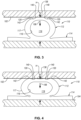
- the load-displacement curve 174 of the chart 170 of Figure 10 As indicated by the load-displacement curve 174 of the chart 170 of Figure 10 , as the elastomeric compression spring 110 of Figures 1 and 2 is compressed (e.g., displaced), the compression resistance load generated by the elastomeric compression spring 110 increases at a fairly constant rate. However, as shown in Figure 3 , once the elastomeric compression spring 110 is sufficiently compressed (i.e., at displacement A of Figure 10 ), such that the first part 102 comes in contact with the leading edges 140 of the grooves 120, the load-displacement rate begins to decrease, due to the decreasing thickness (T) of the tube 112 along a first portion of the grooves 120.
- T thickness
- the load-displacement rate continuously decreases under further compression of the elastomeric compression spring 110 until the displacement of the elastomeric compression spring 110 reaches some point (e.g., midpoint) between the displacement A and a displacement B, at which time the load-displacement rate starts to increase.
- Displacement B corresponds with the displacement of the elastomeric compression spring 110 where the first part 102 comes in contact with the trailing edges 142 of the grooves 120.
- the region of the load-displacement curve 174 between the displacement A and the displacement B is defined as a localized load-displacement reduction region 176.
- the load-displacement curve 174 starts to align with the load-displacement curve 172 of the elastomeric compression spring 110 without the grooves 120.
- the localized load-displacement reduction region 176 acts a localized departure from the load-displacement curve 172.
- the characteristics of the localized load-displacement reduction region 176 are based on the configuration of the grooves 120.
- the depth (D) of the grooves 120 corresponds with a magnitude of decrease in the load-displacement rate of the elastomeric compression spring 110 within the localized load-displacement reduction region 176.
- the circumferential distance (d) of the grooves 120 away from the initial contact line 136 corresponds with the displacement of the tube 112 at which the decrease in the load-displacement rate of the elastomeric compression spring 110 begins.
- the circumferential distance (d) of the grooves 120 away from the initial contact line 136 corresponds with displacement A of the load-displacement curve 174.
- the length (L) of the grooves 120 corresponds with the range of displacement of the tube 112 during which the load-displacement rate decreases and departs from the load-displacement curve 172. Accordingly, the length (L) corresponds with displacement B of the load-displacement curve 174.
- any one of the characteristics of the grooves 120 can be modified to predictably and precisely adjust the characteristics of the load-displacement behavior of the elastomeric compression spring 110.
- the grooves 120 can be located a greater circumferential distance (d) away from the initial contact line 136.
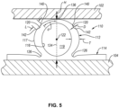
- the circumferential distance (d) of the grooves 120 of the elastomeric compression spring 110 of Figure 5 is greater than that of the elastomeric compression spring 110 of Figure 1 .
- the localized load-displacement reduction region 186 of the resultant load-displacement curve 184 shown in the chart 180 of Figure 11 starts when the elastomeric compression spring 110 is more displaced (e.g., compressed) compared to the elastomeric compression spring 110 of Figure 1 .
- grooves 120 of the elastomeric compression spring 110 of Figure 5 could be wider or narrower (e.g., longer or shorter length (L)) and/or deeper or shallower (e.g., greater or lesser depth (D)) to change the duration and/or magnitude of the localized load-displacement reduction region 186 compared to the localized load-displacement reduction region 176.
- an elastomeric compression spring 110 can be designed and made to achieve unique and predetermined load-displacement behavior in a way that promotes a reduction in design and manufacturing iterations, which helps to increase efficiency, promote cost savings, and reduce labor.
- an elastomeric compression spring can include ribs that generate a localized load-displacement increase region.
- the tube 112 of the elastomeric compression spring 110 includes at least one rib 150 formed in the outer surface 117 of the tube 112. As will be described in more detail, the rib 150 creates a localized increase in the thickness (T) of the tube 112, which causes a localized increase in the stiffness of the elastomeric compression spring 110 at the rib 150.
- the rib 150 is formed into the outer surface 117 of the tube 112 at a location that is circumferentially spaced apart from the initial contact line 136.
- the elastomeric compression spring 110 of Figures 8 and 9 can have the same features and configuration as the above-described features and configuration of the elastomeric compression spring 110 of Figures 1 and 2 .
- the rib 150 is elongated and extends parallel to the central axis 122 (see, e.g., Figure 8 ). In cross-section, as shown in Figure 9 , the rib 150 is convex and thus effectually defines a convex outer surface of the tube 112.
- the rib 150 has a curved concave shape with constant radius of curvature.
- the rib 150 can have a non-curved concave shape, such as a polygonal shape, or a curved concave shape with a changing radius of curvature.
- the radius of curvature of the rib 150 is less than the radius of curvature of the outer surface 117 of the tube 112. Accordingly, the rib 150 protrudes from the outer surface 117 of the tube 112.
- the rib 150 has a height (h) equal to the distance between a crest or apex of the rib 150 and the hypothetical continuation of the curvature of the outer surface 117 of the tube 112 over the groove 120, as shown in dashed line in Figure 9 . Because the rib 150 effectually increases the amount of material of the tube 112, the thickness (T) of the tube 112 at the rib 150 is more than at other non-ribbed portions of the tube 112, such as those portions directly adjacent the rib 150.
- the thickness (T) of the tube 112 when moving along the tube 112 in a circumferential direction toward the initial contact line 136 increases and then decreases along the rib 150 (e.g., along the portion of the tube 112 defined by the rib 150).
- the rib 150 also has a length (L) equal to the distance between a leading edge 152 of the rib 150 and a trailing edge 154 of the rib 150.
- the length (L) can be considered a circumferential length in some implementations.
- the rib 150 is located on the outer surface 117 of the tube 112 a circumferential distance (d) away from the initial contact line 136. More specifically, the leading edge 152 of the rib 150 is a circumferential distance (d) away from the initial contact line 136 and the trailing edge 154 is the circumferential distance (d) plus the length (L) of the rib 150 away from the initial contact line 136.
- the tube 112 of the elastomeric compression spring 110 has two ribs 150 formed in the outer surface 117 on opposite sides of the initial contact line 136.
- the two ribs 150 are circumferentially spaced the same distance from the initial contact line 136. In other words, the circumferential distance (d) for both ribs 150 is the same.
- the ribs 150 can be identically sized and shaped such that one side of the tube 112 is a mirror image of the other side of the tube 112.
- the tube 112 of the illustrated example includes just two ribs 150, in other examples, the tube 112 can include more than two ribs 150, such as four ribs 150.
- the tube 112 of Figure 2 is shown optionally to have two additional ribs 150 formed in the outer surface 117 with each rib 150 on an opposite side of the initial contact line 136.
- the two additional ribs 150 can be spaced the same circumferential distance from the initial contact line 136 and the same circumferential distance away from the corresponding adjacent rib 150.
- the tube 112 may have more than four ribs 150.
- the tube 112 can have two or more grooves 120 and two or more ribs 150 to provide an elastomeric compression spring 110 that has both a bump decrease and a bump increase in its load-displacement rate.
- a first part e.g., a part similar to the first part 102 of Figure 2 and movable into contact with the elastomeric compression spring 110
- a second part e.g., a part similar to the second part 104 of Figure 2 and supporting the elastomeric compression spring 110
- compresses e.g., resiliently deforms
- the load-displacement curve 194 of the chart 190 of Figure 12 As indicated by the load-displacement curve 194 of the chart 190 of Figure 12 , as the elastomeric compression spring 110 of Figures 8 and 9 is compressed (e.g., displaced), the compression resistance load generated by the elastomeric compression spring 110 increases at a fairly constant rate. However, once the elastomeric compression spring 110 is sufficiently compressed (i.e., at displacement A of Figure 12 ), such that the first part comes in contact with the leading edges 152 of the ribs 150, the load-displacement rate begins to increase, greater than if the elastomeric compression spring 110 did not have ribs 150, due to the increasing thickness (T) of the tube 112 along a first portion of the ribs 150.
- T thickness
- the load-displacement rate continuously increases in this manner under further compression of the elastomeric compression spring 110 until the displacement of the elastomeric compression spring 110 reaches some point (e.g., midpoint) between the displacement A and a displacement B, at which time the load-displacement rate starts to decrease.
- Displacement B corresponds with the displacement of the elastomeric compression spring 110 where the first part comes in contact with the trailing edges 154 of the ribs 150.
- the region of the load-displacement curve 194 between the displacement A and the displacement B is defined as a localized load-displacement increase region 196.
- the load-displacement curve 194 starts to align with the load-displacement curve 172 of the elastomeric compression spring 110 without the ribs 150. Accordingly, the localized load-displacement increase region 196 acts a localized departure from the load-displacement curve 172.
- the characteristics of the localized load-displacement increase region 196 are based on the configuration of the ribs 150.
- the depth (D) of the ribs 150 corresponds with a magnitude of increase in the load-displacement rate of the elastomeric compression spring 110 within the localized load-displacement increase region 196.
- the circumferential distance (d) of the ribs 150 away from the initial contact line 136 corresponds with the displacement of the tube 112 at which the increase in the load-displacement rate of the elastomeric compression spring 110 begins.
- the circumferential distance (d) of the ribs 150 away from the initial contact line 136 corresponds with displacement A of the load-displacement curve 174.
- the length (L) of the ribs 150 corresponds with the range of displacement of the tube 112 during which the load-displacement rate increases and departs from the load-displacement curve 172.
- any one of the characteristics of the ribs 150 can be modified to predictably and precisely adjust the characteristics of the load-displacement behavior of the elastomeric compression spring 110 in a manner similar to that described above in relation to the grooves 120.
- the direct correlation between the characteristics of the ribs 150 and the characteristics of the localized load-displacement increase region 196 allows the ribs 150 to be pre-designed and manufactured to predictably and precisely tune the load-displacement behavior of an elastomeric compression spring 110 to achieve a load-displacement increase region 196 with desired characteristics, including a desired location, magnitude, and duration.
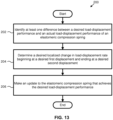
- a method 200 of tuning an elastomeric compression spring 110 includes identifying at least one difference between a desired load-displacement performance and an actual load-displacement performance of an elastomeric compression spring at 202.
- the method 200 further includes determining a desired localized change (e.g., bump) in load-displacement rate beginning at a desired first displacement and ending at a desired second displacement corresponding with the at least one difference between the desired load-displacement performance and the actual load-displacement performance at 204.
- the method 200 also includes making an update to an elastomeric compression spring that achieves the desired load-displacement performance at 204.
- the localized change in the load-displacement rate is a localized decrease (e.g., bump decrease) in the load-displacement rate.
- the update to the elastomeric compression spring in step 206 of the method 200 includes updating at least one groove 120 formed in the outer surface 117 of the elastomeric compression spring 100.
- the groove 120 is configured such that a depth (D) of the groove 120 corresponds with a magnitude of the localized decrease in the load-displacement rate, a circumferential distance (d) of the groove 120 away from the initial contact line 136 of the tube 112 corresponds with the desired first displacement, and a length (L) of the groove 120 corresponds with the desired second displacement.
- the localized change in the load-displacement rate is a localized increase (e.g., bump increase) in the load-displacement rate.
- the update to the elastomeric compression spring in step 206 of the method 200 includes updating at least one rib 150 formed in the outer surface 117 of the elastomeric compression spring 110.
- the rib 150 is configured such that a height (h) of the rib 150 corresponds with a magnitude of the localized increase in the load-displacement rate, a circumferential distance (d) of the rib 150 away from the initial contact line 136 of the tube 112 corresponds with the desired first displacement, and a length (L) of the rib 150 corresponds with the desired second displacement.
Landscapes
- Engineering & Computer Science (AREA)
- General Engineering & Computer Science (AREA)
- Mechanical Engineering (AREA)
- Health & Medical Sciences (AREA)
- Child & Adolescent Psychology (AREA)
- Springs (AREA)
Description
- This disclosure relates generally to vibration isolators, and more particularly to elastomeric compression springs.
- Elastomeric compression springs are used to isolate vibrations in some applications. Such elastomeric compression springs are configured to isolate vibrations according to the load-displacement performance and frequency response of the elastomeric compression springs. Manufacturing an elastomeric compression spring to achieve a particular load-displacement performance, without excessive trial-and-error iterations, can be difficult.
- Document
US 7527454 B1 discloses a marine fender for protecting a marine structure and watercraft against damage from collision forces. The marine fender includes an elongate body of resilient material having a basal wall dimensioned and configured for mounting the marine fender on the marine structure, and an outer wall for being engaged by a collision force, the basal wall and the outer wall defining an inner space. A web within the inner space is integral with the basal wall and with the outer wall, and has a generally M-shaped lateral cross-sectional configuration enabling cushioning by the outer wall and establishing an integral reinforcing and energy absorbing construction within the inner space for protecting against damage to the marine structure from collision forces exerted against the outer wall, as well as against damage to the watercraft. - Document
WO 86/00051 A1 - Document
EP 2902269 A1 discloses a device to reduce the collision force comprising a collisional part and a fixed part. The device to reduce the collision force is an integral structure of integrated molding production. The collisional part includes an inner layer and an outer layer. A cavity is formed by means of the segmentation of a separated reinforcement between the inner layer and the outer layer. The outer layer of the collisional part is in arc shape and a curved surface bulges outward. - The subject matter of the present application has been developed in response to the present state of the art, and in particular, in response to the shortcomings of elastomeric compression springs and associated methods of manufacture, that have not yet been fully solved by currently available techniques. Accordingly, the subject matter of the present application has been developed to provide examples of an elastomeric compression spring and associated methods of manufacturing the elastomeric compression spring that overcome at least some of the above-discussed shortcomings of prior art techniques.
- Disclosed herein is an elastomeric compression spring having the features disclosed in
claim 1. The dependent claims outline advantageous forms of embodiment thereof. Additionally, claims 12-14 disclose a method for tuning an elastomeric compression spring. Yet, claim 15 discloses the use of an elastomeric compression spring for isolating vibrations between two parts. The first part is movable in a direction relative to the second part. The elastomeric compression spring comprises a tube elongated along a central axis of the tube. The central axis of the tube is perpendicular to the direction. The tube is configured to compress in the direction. The tube comprises an outer surface comprising an initial contact line configured to initially receive contact from the first part. The tube further comprises at least one groove formed in the outer surface, parallel to the central axis, and circumferentially spaced apart from the initial contact line. The at least one groove creates a localized reduction in a thickness of the tube and a stiffness of the elastomeric compression spring at the at least one groove
The tube may further comprise two grooves formed in the outer surface of the tube on opposite sides of the initial contact line. - The two grooves may be circumferentially spaced a same distance from the initial contact line.
- The tube may further comprise four grooves formed in the outer surface of the tube. Two of the four grooves are on a side of the initial contact line opposite that of the other two of the four grooves.
- The outer surface of the tube may have a curved convex shape. The at least one groove may have a curved concave shape.
- The tube may be made of a thermoplastic elastomer.
- The thickness of the tube, when moving along the tube in a circumferential direction toward the initial contact line, may decrease and increase along the at least one groove.
- A depth of the at least one groove may correspond with a magnitude of decrease in a load-displacement rate of the elastomeric compression spring. A length of the at least one groove may correspond with a range of displacement of the tube during which the load-displacement rate decreases. A circumferential distance of the at least one groove away from the initial contact line may correspond with a displacement of the tube at which the decrease in the load-displacement rate of the elastomeric compression spring begins.
- Also disclosed herein is an elastomeric compression spring for isolating vibrations between a first part and a second part. The first part is movable in a direction relative to the second part. The elastomeric compression spring includes a tube elongated along a central axis of the tube. The central axis of the tube is perpendicular to the direction. The tube is configured to compress in the direction. The tube comprises an outer surface comprising an initial contact line configured to initially receive contact from the first part. The tube further comprises at least one rib formed in the outer surface, parallel to the central axis, and circumferentially spaced apart from the initial contact line. The at least one rib creates a localized increase in a thickness of the tube and a stiffness of the elastomeric compression spring at the at least one rib.
- The tube may further comprise two ribs formed in the outer surface of the tube on opposite sides of the initial contact line.
- The two ribs may be circumferentially spaced a same distance from the initial contact line.
- The tube may further comprise four ribs formed in the outer surface of the tube. Two of the four ribs are on a side of the initial contact line opposite that of the other two of the four ribs.
- The outer surface of the tube may have a curved convex shape. The at least one rib has a curved convex shape with a radius of curvature less than that of the curved convex shape of the outer surface of the tube.
- The thickness of the tube, when moving along the tube in a circumferential direction toward the initial contact line, may increase and decrease along the at least one rib.
- A height of the at least one rib may correspond with a magnitude of increase in a load-displacement rate of the elastomeric compression spring. A length of the at least one rib may correspond with a range of displacement of the tube during which the load-displacement rate is increased. A circumferential distance of the at least one rib away from the initial contact line may correspond with a displacement of the tube at which the increase in the load-displacement rate of the elastomeric compression spring begins.
- Additionally disclosed herein is a method of tuning an elastomeric compression spring. The method comprises identifying at least one difference between a desired load-displacement performance and an actual load-displacement performance of an elastomeric compression spring. The method also comprises determining a desired localized decrease in a load-displacement rate beginning at a desired first displacement and ending at a desired second displacement corresponding with the at least one difference between the desired load-displacement performance and the actual load-displacement performance. The method further comprises updating at least one groove formed in an outer surface of a tube of the elastomeric compression spring, according to the desired localized decrease in the load-displacement rate, to achieve the desired load-displacement performance.
- The elastomeric compression spring may be updated such that a depth of the at least one groove corresponds with a magnitude of the desired localized decrease in the load-displacement rate, a circumferential distance of the at least one groove away from an initial contact line of the tube corresponds with the desired first displacement, and a length of the at least one groove corresponds with the desired second displacement.
- Also disclosed herein is a method of tuning an elastomeric compression spring. The method comprises identifying at least one difference between a desired load-displacement performance and an actual load-displacement performance of an elastomeric compression spring. The method also comprises determining a desired localized increase in a load-displacement rate beginning at a desired first displacement and ending at a desired second displacement corresponding with the at least one difference between the desired load-displacement performance and the actual load-displacement performance. The method further comprises updating at least one rib formed in an outer surface of a tube of the elastomeric compression spring, according to the desired localized increase in the load-displacement rate, to achieve the desired load-displacement performance.
- The elastomeric compression spring may be updated such that a height of the at least one rib corresponds with a magnitude of the desired localized increase in the load-displacement rate, a circumferential distance of the at least one rib away from an initial contact line of the tube corresponds with the desired first displacement, and a length of the at least one rib corresponds with the desired second displacement. The features and advantages of the subject matter of the present disclosure will become more fully apparent from the following description and appended claims, or may be learned by the practice of the subject matter as set forth hereinafter.
- In order that the advantages of the subject matter may be more readily understood, a more particular description of the subject matter briefly described above will be rendered by reference to specific examples that are illustrated in the appended drawings. Understanding that these drawings depict only typical examples of the subject matter and are not therefore to be considered to be limiting of its scope, the subject matter will be described and explained with additional specificity and detail through the use of the drawings, in which:
-
Figure 1 is a perspective view of an elastomeric compression spring, according to one or more examples of the present disclosure; -
Figure 2 is a front elevation view of the elastomeric compression spring ofFigure 1 between two parts, according to one or more examples of the present disclosure; -
Figure 3 is a front elevation view of the elastomeric compression spring ofFigure 1 , shown compressed between two parts, according to one or more examples of the present disclosure; -
Figure 4 is a front elevation view of the elastomeric compression spring ofFigure 1 , shown compressed between two parts, according to one or more examples of the present disclosure; -
Figure 5 is a front elevation view of an elastomeric compression spring between two parts, according to one or more examples of the present disclosure; -
Figure 6 is a front elevation view of the elastomeric compression spring ofFigure 5 , shown compressed between the two parts, according to one or more examples of the present disclosure; -
Figure 7 is a front elevation view of the elastomeric compression spring ofFigure 5 , shown compressed between the two parts, according to one or more examples of the present disclosure; -
Figure 8 is a perspective view of an elastomeric compression spring, according to one or more examples of the present disclosure; -
Figure 9 is a front elevation view of the elastomeric compression spring ofFigure 8 between two parts, according to one or more examples of the present disclosure; -
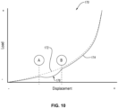
Figure 10 is a chart showing a load-displacement performance of the elastomeric compression spring ofFigure 1 , according to one or more examples of the present disclosure; -
Figure 11 is a chart showing a load-displacement performance of the elastomeric compression spring ofFigure 5 , according to one or more examples of the present disclosure; -
Figure 12 is a chart showing a load-displacement performance of the elastomeric compression spring ofFigure 8 , according to one or more examples of the present disclosure; and -
Figure 13 is a schematic flow chart of a method of tuning an elastomeric compression spring, according to one or more examples of the present disclosure. - Referring to
Figures 1 and 2 , anelastomeric compression spring 110, according to one example, is shown. Theelastomeric compression spring 110 is configured to isolate vibrations between afirst part 102 and a second part 104 (see, e.g.,Figure 2 ). As defined herein, a vibration is defined as relative movement between two parts. Thefirst part 102 is movable relative to thesecond part 104 in adirection 106. In some implementations, movement of thefirst part 102 relative to the second part 104 (also defined as movement of thesecond part 104 relative to the first part 102) can be intentional or controllable movement, such as the opening and closing of a door relative to a frame. However, in other implementations, movement of thefirst part 102 relative to thesecond part 104 can be unintentional or uncontrollable, such as vibrations between an engine and a frame caused by normal operation of the engine. Theelastomeric compression spring 110 isolates vibrations, or relative movement, between thefirst part 102 and thesecond part 104. Moreover, the vibration isolation characteristics of theelastomeric compression spring 110 are tunable (e.g., customizable) to predictably achieve a desired load-displacement and/or frequency performance based on an intended use of theelastomeric compression spring 110. - The
elastomeric compression spring 110 includes abase 114 and atube 112 coupled to thebase 114. Thebase 114 provides a platform on which thetube 112 is supported. Generally, thebase 114 is configured to fixedly engage thesecond part 104 such that thetube 112 is fixedly engaged with thesecond part 104 and interposed between thefirst part 102 and thesecond part 104. The base 114 can be fixedly engaged with thesecond part 104 in various ways. For example, the base 114 can be adhered to, bonded to, fastened to, interference fitted to, and/or interlocked with thesecond part 104. The base 114 may have an engagement surface configured to complementary engage a corresponding surface of thesecond part 104. In the illustrated example, thebase 114 has a flat surface that engages a flat surface of thesecond part 104. Although the base 114 can have any of various shapes and sizes capable of anchoring thetube 112 relative to thesecond part 104, in the illustrated example, thebase 114 has a thin-walled rectangular shape and a footprint greater than that of thetube 112. In some examples, theelastomeric compression spring 110 does not include a base 114 (e.g., thetube 112 can be attached direction to the second part 104). - The
tube 112 protrudes away from the base 114 such that, when thebase 114 is engaged with thesecond part 104, thetube 112 is interposed between the base 114 and thefirst part 102. Generally, thetube 112 is defined as a circumferentially closed sidewall. Thetube 112 defines acentral axis 122 along which thetube 112 is elongated. Thecentral axis 122 is a geometric center of thetube 112 in some examples. As defined herein, thetube 112 is hollow, which facilitates compression of thetube 112. Accordingly, thetube 112 includes a hollowinterior channel 119 that extends the length of thetube 112 along thecentral axis 122. Thetube 112 includes aninner surface 116 and anouter surface 117. Theinner surface 116 faces towards thecentral axis 122 while theouter surface 117 faces away from thecentral axis 122. Correspondingly, theinner surface 116 is concave and theouter surface 117 is convex. Theinner surface 116 defines the hollowinterior channel 119. - Although the
tube 112 in the illustrated examples is a hollow elongate tube, in other examples, thetube 112 can have a hollow spherical shape. The hollow spherically-shaped tube could have the same cross-sectional shape as that of the hollow elongate tube. However, the cross-sectional shape of the hollow spherically-shaped tube would revolve 360-degrees, instead of linearly along an axis. One ormore grooves 120 orribs 150, as described below, would extend continuously or discontinuously circumferentially about the hollow spherical shape. - The
tube 112 has a thickness (T) defined as the minimum distance between theinner surface 116 and theouter surface 117 at any point around thetube 112. In some examples, the thickness (T) is more particularly defined as the distance between theinner surface 116 and theouter surface 117 in a direction radially away from thecentral axis 122. The thickness (T) of thetube 112 can vary at different locations circumferentially along thetube 112. In other words, when moving along thetube 112 in a circumferential direction, the thickness (T) of thetube 112 can vary. - The thickness (T) of the
tube 112 is related to the stiffness of thetube 112. In other words, for a given material, the thicker thetube 112, then the stiffer thetube 112. Moreover, the stiffness of thetube 112 affects the vibration isolation characteristics. More specifically, the stiffness of thetube 112 affects the load-displacement performance of theelastomeric compression spring 110. For example, the stiffer thetube 112, then the higher the load for a given displacement of theelastomeric compression spring 110. In contrast, the more flexible thetube 112, the lower the load for a given displacement of theelastomeric compression spring 110. Accordingly, the load-displacement performance of theelastomeric compression spring 110 is a measure of the compression resistance force (e.g., load) generated by theelastomeric compression spring 110 for a given compressive displacement (e.g., compression) of thespring 110. - Generally, as the
elastomeric compression spring 110 is compressed, the compression resistance force or load generated by theelastomeric compression spring 110 increases. In some examples, the load-displacement rate (e.g., the rate at which the load of theelastomeric compression spring 110 changes as theelastomeric compression spring 110 is compressed) also increases as theelastomeric compression spring 110 is further compressed. Referring to thechart 170 and thechart 180Figures 10 and11 , respectively, according to one example, a load-displacement rate represented by a load-displacement curve 172 for theelastomeric compression spring 110, withoutgrooves 120, is shown to continuously increase with continuous compressive displacement. Accordingly, the load-displacement curve 172 is non-linear or curved. In some implementations, the load-displacement curve 172 is considered a fully exponential curve or the load and displacement of theelastomeric compression spring 110 withoutgrooves 120 are fully exponentially related. - In some applications, it may be desirable for an elastomeric compression spring to have a load-displacement rate that does not continuously increase. For example, in certain instances, an elastomeric compression spring with a load-displacement rate that decreases within a desired displacement range of the compression spring may be desirable. In other words, it may be desirable to have an elastomeric compression spring where the load and displacement are only partially exponentially related. To promote a decrease in the load-displacement rate within a desired displacement range, the
tube 112 of theelastomeric compression spring 110 includes at least onegroove 120 formed in theouter surface 117 of thetube 112. As will be described in more detail, thegroove 120 creates a localized reduction in the thickness (T) of thetube 112, which causes a localized reduction in the stiffness of theelastomeric compression spring 110 at thegroove 120. - The
tube 112 further includes aninitial contact line 136, which is a hypothetical or virtual line. Theinitial contact line 136 represents the portion of theouter surface 117 that initially contacts thefirst part 102 as thefirst part 102 moves toward thesecond part 104 in thedirection 106. Accordingly, theelastomeric compression spring 110 is fixedly coupled to thesecond part 104 and oriented such that theinitial contact line 136 initially receives thefirst part 102. In some implementations, movement of thefirst part 102 relative to thesecond part 104 begins with thefirst part 102 in contact with theinitial contact line 136 of thetube 112. In other implementations, thefirst part 102 is moved into contact with theinitial contact line 136 of thetube 112. Thegroove 120 is formed into theouter surface 117 of thetube 112 at a location that is circumferentially spaced apart from theinitial contact line 136. As defined herein, circumferential spacing or a circumferential distance refers to a spacing or distance along an outer periphery of thetube 112 in a direction perpendicular to thecentral axis 122 and does not necessarily imply thetube 112 is cross-sectionally circular, as thetube 112 may a cross-sectional shape other than circular, such as ovular, triangular, rectangular, oblong, and the like. - The
groove 120 is elongated and extends parallel to the central axis 122 (see, e.g.,Figure 1 ). In cross-section, as shown inFigure 2 , thegroove 120 is concave and thus effectually defines a concave outer surface of thetube 112. In the illustrated example, thegroove 120 has a curved concave shape with constant radius of curvature. However, in other examples, thegroove 120 can have a non-curved concave shape, such as a polygonal shape, or a curved concave shape with a changing radius of curvature. - The
groove 120 has a depth (D) equal to the distance between a bottommost point of thegroove 120 and the hypothetical continuation of the curvature of theouter surface 117 of thetube 112 over thegroove 120, as shown in dashed line inFigure 2 . Because thegroove 120 effectually reduces the amount of material of thetube 112, the thickness (T) of thetube 112 at thegroove 120 is less than at other non-grooved portions of thetube 112. Additionally, because thegroove 120 is concave, the thickness (T) of thetube 112, when moving along thetube 112 in a circumferential direction toward theinitial contact line 136 decreases and then increases along the groove 120 (e.g., along the portion of thetube 112 defined by the groove 120). - Additionally, the
groove 120 also has a length (L) equal to the distance between aleading edge 140 of thegroove 120 and a trailingedge 142 of thegroove 120. The length (L) can be considered a circumferential length in some implementations. - Moreover, the
groove 120 is located on theouter surface 117 of the tube 112 a circumferential distance (d) away from theinitial contact line 136. More specifically, theleading edge 140 of thegroove 120 is a circumferential distance (d) away from theinitial contact line 136 and the trailingedge 142 is the circumferential distance (d) plus the length (L) of thegroove 120 away from theinitial contact line 136. The circumferential distance (d) is less than half the circumference or perimeter of a corresponding side of thetube 112 in some implementations. In other words, thegroove 120 is located on an upper half of thetube 112. - In the illustrated example, the
tube 112 of theelastomeric compression spring 110 has twogrooves 120 formed in theouter surface 117 on opposite sides of theinitial contact line 136. In one implementation, the twogrooves 120 are circumferentially spaced the same distance from theinitial contact line 136. In other words, the circumferential distance (d) for bothgrooves 120 is the same. Additionally, thegrooves 120 can be identically sized and shaped such that one side of thetube 112 is a mirror image of the other side of thetube 112. In other words, thetube 112 is symmetrical across a plane ofsymmetry 124 aligned with theinitial contact line 136. - Although the
tube 112 of the illustrated example includes just twogrooves 120, in other examples, thetube 112 can include more than twogrooves 120, such as fourgrooves 120. Thetube 112 ofFigure 2 is shown optionally to have twoadditional grooves 120 formed in theouter surface 117 with eachgroove 120 on an opposite side of theinitial contact line 136. The twoadditional grooves 120 can be spaced the same circumferential distance from theinitial contact line 136 and the same circumferential distance away from the correspondingadjacent groove 120. In yet other examples, thetube 112 may have more than fourgrooves 120. - The
tube 112 can be made of any of various elastomeric (e.g., resiliently flexible) materials in some examples. In one example, thetube 112 is made of a thermoplastic elastomer. In another example, thetube 112 is made of a rubber. Thebase 114 is made of the same material as thetube 112 in one example and made of a different material, such as a non-elastomeric material or a different elastomeric material, in another example. In other examples, thetube 112 could be made of a metallic material, such as for a one-time use (e.g., a crush feature) or only used in the elastic strain regime of the material (e.g., for small deformations). - The
tube 112 and the base 114 are co-formed together to collectively form a one-piece, seamless monolithic construction. However, in other implementations, thetube 112 and the base 114 are formed separately and attached together. According to one example, thetube 112 and/or thebase 114 is formed by extruding a thermoplastic elastomer through a die so as to form a continuous length of thetube 112 and/or thebase 114. - In one example, the
elastomeric compression spring 110 includes aradiused portion 126 at each of the intersections between thetube 112 and thebase 114. Theradiused portion 126 promotes deformity (e.g., compression) of thetube 112 relative to thebase 114, particularly the portion of thetube 112 directly adjacent thebase 114. - Operation of the
elastomeric compression spring 110 ofFigures 1 and 2 as a vibration isolator will now be described. After thefirst part 102 is in contact with theinitial contact line 136 of thetube 112, further movement of thefirst part 102 relative to thesecond part 104, in thedirection 106, compresses (e.g., resiliently deforms) theelastomeric compression spring 110. Compression of theelastomeric compression spring 110 changes a height (H) of theelastomeric compression spring 110. The height (H) of theelastomeric compression spring 110 is defined as the distance between theinitial contact line 136 and the engagement surface of the base 114 or the bottom of thetube 112. - As indicated by the load-
displacement curve 174 of thechart 170 ofFigure 10 , as theelastomeric compression spring 110 ofFigures 1 and 2 is compressed (e.g., displaced), the compression resistance load generated by theelastomeric compression spring 110 increases at a fairly constant rate. However, as shown inFigure 3 , once theelastomeric compression spring 110 is sufficiently compressed (i.e., at displacement A ofFigure 10 ), such that thefirst part 102 comes in contact with the leadingedges 140 of thegrooves 120, the load-displacement rate begins to decrease, due to the decreasing thickness (T) of thetube 112 along a first portion of thegrooves 120. The load-displacement rate continuously decreases under further compression of theelastomeric compression spring 110 until the displacement of theelastomeric compression spring 110 reaches some point (e.g., midpoint) between the displacement A and a displacement B, at which time the load-displacement rate starts to increase. - Displacement B corresponds with the displacement of the
elastomeric compression spring 110 where thefirst part 102 comes in contact with the trailingedges 142 of thegrooves 120. The region of the load-displacement curve 174 between the displacement A and the displacement B is defined as a localized load-displacement reduction region 176. At displacement B, the load-displacement curve 174 starts to align with the load-displacement curve 172 of theelastomeric compression spring 110 without thegrooves 120. Accordingly, the localized load-displacement reduction region 176 acts a localized departure from the load-displacement curve 172. - The characteristics of the localized load-
displacement reduction region 176 are based on the configuration of thegrooves 120. For example, the depth (D) of thegrooves 120 corresponds with a magnitude of decrease in the load-displacement rate of theelastomeric compression spring 110 within the localized load-displacement reduction region 176. The circumferential distance (d) of thegrooves 120 away from theinitial contact line 136 corresponds with the displacement of thetube 112 at which the decrease in the load-displacement rate of theelastomeric compression spring 110 begins. In other words, the circumferential distance (d) of thegrooves 120 away from theinitial contact line 136 corresponds with displacement A of the load-displacement curve 174. The length (L) of thegrooves 120 corresponds with the range of displacement of thetube 112 during which the load-displacement rate decreases and departs from the load-displacement curve 172. Accordingly, the length (L) corresponds with displacement B of the load-displacement curve 174. - Any one of the characteristics of the
grooves 120 can be modified to predictably and precisely adjust the characteristics of the load-displacement behavior of theelastomeric compression spring 110. For example, referring toFigures 5-7 , if anelastomeric compression spring 110, having a localized load-displacement reduction region that occurs at a greater displacement of theelastomeric compression spring 110 than the localized load-displacement reduction region 176, is desired, thegrooves 120 can be located a greater circumferential distance (d) away from theinitial contact line 136. The circumferential distance (d) of thegrooves 120 of theelastomeric compression spring 110 ofFigure 5 is greater than that of theelastomeric compression spring 110 ofFigure 1 . Accordingly, as theelastomeric compression spring 110 ofFigure 5 is compressed (see, e.g.,Figures 6 and 7 ), the localized load-displacement reduction region 186 of the resultant load-displacement curve 184 shown in thechart 180 ofFigure 11 starts when theelastomeric compression spring 110 is more displaced (e.g., compressed) compared to theelastomeric compression spring 110 ofFigure 1 . Although not shown, thegrooves 120 of theelastomeric compression spring 110 ofFigure 5 could be wider or narrower (e.g., longer or shorter length (L)) and/or deeper or shallower (e.g., greater or lesser depth (D)) to change the duration and/or magnitude of the localized load-displacement reduction region 186 compared to the localized load-displacement reduction region 176. - The direct correlation between the characteristics of the
grooves 120 and the characteristics of the localized load-displacement reduction region 176 allows thegrooves 120 to be pre-designed and manufactured to predictably and precisely tune the load-displacement behavior of anelastomeric compression spring 110 to achieve a load-displacement reduction region 176 with desired characteristics, including a desired location, magnitude, and duration. Accordingly, as described in more detail below in association with themethod 200 ofFigure 13 , anelastomeric compression spring 110 can be designed and made to achieve unique and predetermined load-displacement behavior in a way that promotes a reduction in design and manufacturing iterations, which helps to increase efficiency, promote cost savings, and reduce labor. - In some applications and contexts, it may be desirable for an elastomeric compression spring to produce a load-displacement curve with a localized load-displacement increase region, within which a load-displacement rate substantially sharply increases, to promote added stiffness across a range of displacement of the elastomeric compression spring. Accordingly, instead of, or in addition to, grooves, an elastomeric compression spring can include ribs that generate a localized load-displacement increase region. For example, referring to
Figures 8 and 9 , to promote a sharp increase, or increase bump, in the load-displacement rate within a desired displacement range, thetube 112 of theelastomeric compression spring 110 includes at least onerib 150 formed in theouter surface 117 of thetube 112. As will be described in more detail, therib 150 creates a localized increase in the thickness (T) of thetube 112, which causes a localized increase in the stiffness of theelastomeric compression spring 110 at therib 150. - The
rib 150 is formed into theouter surface 117 of thetube 112 at a location that is circumferentially spaced apart from theinitial contact line 136. With the exception ofribs 150 instead ofgrooves 120, in some examples, theelastomeric compression spring 110 ofFigures 8 and 9 can have the same features and configuration as the above-described features and configuration of theelastomeric compression spring 110 ofFigures 1 and 2 . - The
rib 150 is elongated and extends parallel to the central axis 122 (see, e.g.,Figure 8 ). In cross-section, as shown inFigure 9 , therib 150 is convex and thus effectually defines a convex outer surface of thetube 112. In the illustrated example, therib 150 has a curved concave shape with constant radius of curvature. However, in other examples, therib 150 can have a non-curved concave shape, such as a polygonal shape, or a curved concave shape with a changing radius of curvature. The radius of curvature of therib 150 is less than the radius of curvature of theouter surface 117 of thetube 112. Accordingly, therib 150 protrudes from theouter surface 117 of thetube 112. - The
rib 150 has a height (h) equal to the distance between a crest or apex of therib 150 and the hypothetical continuation of the curvature of theouter surface 117 of thetube 112 over thegroove 120, as shown in dashed line inFigure 9 . Because therib 150 effectually increases the amount of material of thetube 112, the thickness (T) of thetube 112 at therib 150 is more than at other non-ribbed portions of thetube 112, such as those portions directly adjacent therib 150. Additionally, because therib 150 is convex, the thickness (T) of thetube 112, when moving along thetube 112 in a circumferential direction toward theinitial contact line 136 increases and then decreases along the rib 150 (e.g., along the portion of thetube 112 defined by the rib 150). - Additionally, the
rib 150 also has a length (L) equal to the distance between aleading edge 152 of therib 150 and a trailingedge 154 of therib 150. The length (L) can be considered a circumferential length in some implementations. - Moreover, the
rib 150 is located on theouter surface 117 of the tube 112 a circumferential distance (d) away from theinitial contact line 136. More specifically, theleading edge 152 of therib 150 is a circumferential distance (d) away from theinitial contact line 136 and the trailingedge 154 is the circumferential distance (d) plus the length (L) of therib 150 away from theinitial contact line 136. - In the illustrated example, the
tube 112 of theelastomeric compression spring 110 has tworibs 150 formed in theouter surface 117 on opposite sides of theinitial contact line 136. In one implementation, the tworibs 150 are circumferentially spaced the same distance from theinitial contact line 136. In other words, the circumferential distance (d) for bothribs 150 is the same. Additionally, theribs 150 can be identically sized and shaped such that one side of thetube 112 is a mirror image of the other side of thetube 112. - Although the
tube 112 of the illustrated example includes just tworibs 150, in other examples, thetube 112 can include more than tworibs 150, such as fourribs 150. Thetube 112 ofFigure 2 is shown optionally to have twoadditional ribs 150 formed in theouter surface 117 with eachrib 150 on an opposite side of theinitial contact line 136. The twoadditional ribs 150 can be spaced the same circumferential distance from theinitial contact line 136 and the same circumferential distance away from the correspondingadjacent rib 150. In yet other examples, thetube 112 may have more than fourribs 150. Additionally, although not shown, in certain examples, thetube 112 can have two ormore grooves 120 and two ormore ribs 150 to provide anelastomeric compression spring 110 that has both a bump decrease and a bump increase in its load-displacement rate. - Operation of the
elastomeric compression spring 110 ofFigures 8 and 9 as a vibration isolator will now be described. After a first part (e.g., a part similar to thefirst part 102 ofFigure 2 and movable into contact with the elastomeric compression spring 110) is in contact with theinitial contact line 136 of thetube 112, further movement of the first part relative to a second part (e.g., a part similar to thesecond part 104 ofFigure 2 and supporting the elastomeric compression spring 110), in thedirection 106, compresses (e.g., resiliently deforms) theelastomeric compression spring 110. As indicated by the load-displacement curve 194 of thechart 190 ofFigure 12 , as theelastomeric compression spring 110 ofFigures 8 and 9 is compressed (e.g., displaced), the compression resistance load generated by theelastomeric compression spring 110 increases at a fairly constant rate. However, once theelastomeric compression spring 110 is sufficiently compressed (i.e., at displacement A ofFigure 12 ), such that the first part comes in contact with the leadingedges 152 of theribs 150, the load-displacement rate begins to increase, greater than if theelastomeric compression spring 110 did not haveribs 150, due to the increasing thickness (T) of thetube 112 along a first portion of theribs 150. The load-displacement rate continuously increases in this manner under further compression of theelastomeric compression spring 110 until the displacement of theelastomeric compression spring 110 reaches some point (e.g., midpoint) between the displacement A and a displacement B, at which time the load-displacement rate starts to decrease. - Displacement B corresponds with the displacement of the
elastomeric compression spring 110 where the first part comes in contact with the trailingedges 154 of theribs 150. The region of the load-displacement curve 194 between the displacement A and the displacement B is defined as a localized load-displacement increase region 196. At displacement B, the load-displacement curve 194 starts to align with the load-displacement curve 172 of theelastomeric compression spring 110 without theribs 150. Accordingly, the localized load-displacement increase region 196 acts a localized departure from the load-displacement curve 172. - The characteristics of the localized load-
displacement increase region 196 are based on the configuration of theribs 150. For example, the depth (D) of theribs 150 corresponds with a magnitude of increase in the load-displacement rate of theelastomeric compression spring 110 within the localized load-displacement increase region 196. The circumferential distance (d) of theribs 150 away from theinitial contact line 136 corresponds with the displacement of thetube 112 at which the increase in the load-displacement rate of theelastomeric compression spring 110 begins. In other words, the circumferential distance (d) of theribs 150 away from theinitial contact line 136 corresponds with displacement A of the load-displacement curve 174. The length (L) of theribs 150 corresponds with the range of displacement of thetube 112 during which the load-displacement rate increases and departs from the load-displacement curve 172. - Any one of the characteristics of the
ribs 150 can be modified to predictably and precisely adjust the characteristics of the load-displacement behavior of theelastomeric compression spring 110 in a manner similar to that described above in relation to thegrooves 120. The direct correlation between the characteristics of theribs 150 and the characteristics of the localized load-displacement increase region 196 allows theribs 150 to be pre-designed and manufactured to predictably and precisely tune the load-displacement behavior of anelastomeric compression spring 110 to achieve a load-displacement increase region 196 with desired characteristics, including a desired location, magnitude, and duration. - Referring to
Figure 13 , according to one example, amethod 200 of tuning anelastomeric compression spring 110 includes identifying at least one difference between a desired load-displacement performance and an actual load-displacement performance of an elastomeric compression spring at 202. Themethod 200 further includes determining a desired localized change (e.g., bump) in load-displacement rate beginning at a desired first displacement and ending at a desired second displacement corresponding with the at least one difference between the desired load-displacement performance and the actual load-displacement performance at 204. Themethod 200 also includes making an update to an elastomeric compression spring that achieves the desired load-displacement performance at 204. - In some implementations, the localized change in the load-displacement rate is a localized decrease (e.g., bump decrease) in the load-displacement rate. Moreover, the update to the elastomeric compression spring in
step 206 of themethod 200 includes updating at least onegroove 120 formed in theouter surface 117 of the elastomeric compression spring 100. Thegroove 120 is configured such that a depth (D) of thegroove 120 corresponds with a magnitude of the localized decrease in the load-displacement rate, a circumferential distance (d) of thegroove 120 away from theinitial contact line 136 of thetube 112 corresponds with the desired first displacement, and a length (L) of thegroove 120 corresponds with the desired second displacement. - In other implementations, the localized change in the load-displacement rate is a localized increase (e.g., bump increase) in the load-displacement rate. Moreover, the update to the elastomeric compression spring in
step 206 of themethod 200 includes updating at least onerib 150 formed in theouter surface 117 of theelastomeric compression spring 110. Therib 150 is configured such that a height (h) of therib 150 corresponds with a magnitude of the localized increase in the load-displacement rate, a circumferential distance (d) of therib 150 away from theinitial contact line 136 of thetube 112 corresponds with the desired first displacement, and a length (L) of therib 150 corresponds with the desired second displacement.
Claims (15)
- An elastomeric compression spring (110) comprising:
an elongated hollow tube (112) defined as a circumferentially closed sidewall having a central axis (122), wherein:the tube (112) includes an inner surface (116) facing towards the central axis (122) and an outer surface (117) facing away from the central axis (122), the outer surface (117) and the inner surface (116) being separated by a variable distance defining a thickness (T) of the tube (112), the thickness being related to a stiffness of the tube (112);the central axis (122) is a geometric center of the tube (112);the elongated hollow tube (112) is configured to compress in a direction (106) perpendicular to the central axis (122);the outer surface (117) of the elongated hollow tube (112) comprises an initial contact line (136) configured to initially receive a compressing contact;the elongated hollow tube (112) further comprises either at least one groove (120) formed in the outer surface (117), parallel to the central axis (122), and circumferentially spaced apart from the initial contact line (136);whereby the at least one groove (120) creates a localized reduction in a thickness (T) of the elongated hollow tube (112) and a stiffness of the elastomeric compression spring (110) at the at least one groove (120), wherein a depth (D) of the at least one groove (120) corresponds with a magnitude of decrease in a load-displacement rate of the elastomeric compression spring (110);a length (L) of the at least one groove (120) corresponds with a range of displacement of the elongated hollow tube (112) during which the load-displacement rate decreases; anda circumferential distance (d) of the at least one groove (120) away from the initial contact line (136) corresponds with a displacement of the elongated hollow tube (112) at which the decrease in the load-displacement rate of the elastomeric compression spring (110) begins;or at least one rib (150) formed in the outer surface (117), parallel to the central axis (122), and circumferentially spaced apart from the initial contact line (136);whereby the at least one rib (150) creates a localized increase in a thickness (T) of the elongated hollow tube (112) and a stiffness of the elastomeric compression spring (110) at the at least one rib (120),
wherein a height (h) of the at least one rib (150) corresponds with a magnitude of increase in a load-displacement rate of the elastomeric compression spring (110);a length (L) of the at least one rib (150) corresponds with a range of displacement of the elongated hollow tube (112) during which the load-displacement rate is increased; anda circumferential distance (d) of the at least one rib (150) away from the initial contact line (136) corresponds with a displacement of the elongated hollow tube (112) at which the increase in the load-displacement rate of the elastomeric compression spring (110) begins: - The elastomeric compression spring (110) according to claim 1,
wherein the elongated hollow tube (112) further comprises two grooves (120) formed in the outer surface (117) of the tube (112) on opposite sides of the initial contact line (136). - The elastomeric compression spring (110) according to claim 2,
wherein the two grooves (120) are circumferentially spaced a same distance from the initial contact line (136). - The elastomeric compression spring (110) according to claim 2,
wherein:the elongated hollow tube (112) further comprises four grooves (120) formed in the outer surface (117) of the tube (112); andtwo of the four grooves (120) are on a side of the initial contact line (136) opposite that of the other two of the four grooves (120). - The elastomeric compression spring (110) according to any one of claims 1-4, wherein:the outer surface (117) of the elongated hollow tube (112) has a curved convex shape; andthe at least one groove (120) has a curved concave shape.
- The elastomeric compression spring (110) according to any one of claims 1-5, wherein the elongated hollow tube (112) is made of a thermoplastic elastomer.
- The elastomeric compression spring (110) according to any one of claims 1-6, wherein the thickness (T) of the elongated hollow tube (112), when moving along the tube (112) in a circumferential direction toward the initial contact line (136), decreases and increases along the at least one groove (120).
- The elastomeric compression spring (110) according to claim 1,
wherein the elongated hollow tube (112) further comprises two ribs (150) formed in the outer surface (117) of the elongated hollow tube (112) on opposite sides of the initial contact line (136). - The elastomeric compression spring (110) according to claim 8,
wherein the two ribs (150) are circumferentially spaced a same distance from the initial contact line (136). - The elastomeric compression spring (110) according to claim 8,
wherein:the elongated hollow tube (112) further comprises four ribs (150) formed in the outer surface (117) of the elongated hollow tube (112); andtwo of the four ribs (150) are on a side of the initial contact line (136) opposite that of the other two of the four ribs (150). - The elastomeric compression spring (110) according to any one of the preceding claims, wherein the elongated hollow tube (112) is coupled to a supporting base (114).
- A method (200) of tuning an elastomeric compression spring (110) constituted by an elongated hollow tube (112) having a central axis (122), the method (200) comprising:identifying at least one difference between a desired load-displacement performance and an actual load-displacement performance of the elastomeric compression spring;determining a desired localized decrease or increase in a load-displacement rate beginning at a desired first displacement and ending at a desired second displacement corresponding with the at least one difference between the desired load-displacement performance and the actual load-displacement performance; andupdating at least one groove (120) or one rib (150) formed in an outer surface (117) of the elongated hollow tube (112), according to the desired localized decrease or increase in the load-displacement rate, to achieve the desired load-displacement performance.
- The method (200) according to claim 12, wherein the elastomeric compression spring (110) is updated such that:a depth (D) of the at least one groove (120) corresponds with a magnitude of the desired localized decrease in the load-displacement rate;a circumferential distance (d) of the at least one groove (120) away from an initial contact line (136) of the tube (112) corresponds with the desired first displacement; anda length (L) of the at least one groove (120) corresponds with the desired second displacement.
- The method (200) according to claim 12, wherein the elastomeric compression spring (110) is updated such that:a height (h) of the at least one rib (150) corresponds with a magnitude of the desired localized increase in the load-displacement rate;a circumferential distance (d) of the at least one rib (150) away from an initial contact line (136) of the tube (112) corresponds with the desired first displacement; anda length (L) of the at least one rib (150) corresponds with the desired second displacement.
- Use of an elastomeric compression spring (110) according to any one of claims 1-10 to isolate vibrations or relative movement between a first part (102) and a second part (104).
Applications Claiming Priority (1)
| Application Number | Priority Date | Filing Date | Title |
|---|---|---|---|
| US16/028,014 US10962073B2 (en) | 2018-07-05 | 2018-07-05 | Elastomeric compression spring with load tuning feature and associated method of tuning |
Publications (2)
| Publication Number | Publication Date |
|---|---|
| EP3591254A1 EP3591254A1 (en) | 2020-01-08 |
| EP3591254B1 true EP3591254B1 (en) | 2024-08-07 |
Family
ID=66857743
Family Applications (1)
| Application Number | Title | Priority Date | Filing Date |
|---|---|---|---|
| EP19179916.2A Active EP3591254B1 (en) | 2018-07-05 | 2019-06-13 | Elastomeric compression spring with load tuning feature and associated method of tuning |
Country Status (3)
| Country | Link |
|---|---|
| US (2) | US10962073B2 (en) |
| EP (1) | EP3591254B1 (en) |
| CN (1) | CN110686032A (en) |
Families Citing this family (4)
| Publication number | Priority date | Publication date | Assignee | Title |
|---|---|---|---|---|
| WO2021250945A1 (en) * | 2020-06-08 | 2021-12-16 | 富士フイルム株式会社 | Endoscope tip protector |
| EP4379230A4 (en) * | 2021-07-30 | 2025-07-02 | Nature Arch Inc | STRUCTURE |
| US12337948B2 (en) * | 2022-02-02 | 2025-06-24 | Textron Innovations Inc. | Bifold stair system for aircraft |
| JP2025519470A (en) * | 2022-06-07 | 2025-06-26 | メタセイズミック インク. | Three adaptive devices for shock and vibration protection |
Family Cites Families (26)
| Publication number | Priority date | Publication date | Assignee | Title |
|---|---|---|---|---|
| US3638985A (en) * | 1969-06-26 | 1972-02-01 | Ford Motor Co | Energy absorbing bumper |
| US3608882A (en) * | 1969-08-20 | 1971-09-28 | Goodyear Tire & Rubber | Elastomeric buffer mounting assembly |
| US3820495A (en) | 1973-02-07 | 1974-06-28 | Bridgestone Tire Co Ltd | Fender |
| US4428568A (en) * | 1981-07-08 | 1984-01-31 | Rubber Millers, Inc. | Force-absorbing device |
| JPS58168706A (en) | 1982-03-31 | 1983-10-05 | Bridgestone Corp | Fender |
| KR860000178A (en) | 1984-06-08 | 1986-01-27 | 이상춘 | Buffer rubber |
| US5791637A (en) * | 1996-01-11 | 1998-08-11 | Iso Dynamics, Inc. | Energy absorbing compression spring body and method of making the same |
| JPH101927A (en) | 1996-06-13 | 1998-01-06 | Bridgestone Corp | Rubber fender |
| US5762016A (en) * | 1997-02-19 | 1998-06-09 | Parsons; Tom | Dock pole bumper assembly |
| CA2301845A1 (en) * | 1997-08-08 | 1999-02-18 | Robert Prentice Beckett | Improvements relating to fenders |
| US6289836B1 (en) * | 2000-03-13 | 2001-09-18 | Michael Tellex | Marine fender |
| US6685395B1 (en) * | 2002-07-31 | 2004-02-03 | Pawling Corporation | Piling fender |
| US6830410B2 (en) * | 2002-12-31 | 2004-12-14 | Sunstream Corporation | Bunk beam and bunk cushion apparatus for supporting a watercraft |
| US7090206B2 (en) * | 2003-01-29 | 2006-08-15 | Wylie Chase | Bumper system |
| DE602004027756D1 (en) * | 2003-11-18 | 2010-07-29 | Innovation Central Pty Ltd | ELASTIC PROTECTION DEVICE FOR PROTECTING A STRUCTURE FROM IMPACT |
| US20060149517A1 (en) * | 2004-12-30 | 2006-07-06 | Caterpillar Inc. | Methods and systems for spring design and analysis |
| US20100275702A1 (en) * | 2006-11-08 | 2010-11-04 | Siemens Water Technologies Corp. | Rotary valve |
| US7527454B1 (en) * | 2008-07-21 | 2009-05-05 | Donald Brushaber | Marine fender |
| US8480333B2 (en) * | 2008-12-26 | 2013-07-09 | Steven Edward DeMay | Frame rail assemblies and interlocking frame rail systems |
| CN102897123B (en) | 2012-09-26 | 2014-10-22 | 桐乡市小老板特种塑料制品有限公司 | Device for buffering striking force |
| EP2938506B1 (en) * | 2012-12-31 | 2024-05-15 | Basf Se | Jounce bumper assembly |
| JP6147508B2 (en) * | 2013-01-15 | 2017-06-14 | 大和化成工業株式会社 | Cushion clip |
| CN203362928U (en) * | 2013-06-21 | 2013-12-25 | 上汽通用五菱汽车股份有限公司 | Plate spring liner |
| AU2014320099B2 (en) * | 2013-09-16 | 2018-07-05 | A-Fax Limited | Structure protector |
| US9528238B2 (en) * | 2013-12-03 | 2016-12-27 | Zachary Taylor | Light altering bumper device |
| US9840820B2 (en) * | 2014-10-29 | 2017-12-12 | Zachary Taylor | Light altering bumper device |
-
2018
- 2018-07-05 US US16/028,014 patent/US10962073B2/en active Active
-
2019
- 2019-06-13 EP EP19179916.2A patent/EP3591254B1/en active Active
- 2019-07-01 CN CN201910584103.XA patent/CN110686032A/en active Pending
-
2021
- 2021-02-05 US US17/168,596 patent/US11754136B2/en active Active
Also Published As
| Publication number | Publication date |
|---|---|
| US11754136B2 (en) | 2023-09-12 |
| EP3591254A1 (en) | 2020-01-08 |
| US10962073B2 (en) | 2021-03-30 |
| CN110686032A (en) | 2020-01-14 |
| US20200011393A1 (en) | 2020-01-09 |
| US20210156443A1 (en) | 2021-05-27 |
Similar Documents
| Publication | Publication Date | Title |
|---|---|---|
| US11754136B2 (en) | Elastomeric compression spring with load tuning feature and associated method of tuning | |
| US3409284A (en) | Elastic hollow spring bodies | |
| JP2000161419A (en) | Bumper spring | |
| US7281705B2 (en) | Jounce assembly for a suspension system | |
| US20170276203A1 (en) | Supplementary spring | |
| CN103921723A (en) | Cushion Clip | |
| US20060071379A1 (en) | Liquid-sealed vibration control device | |
| WO2016006073A1 (en) | Engine cover | |
| EP3976988B1 (en) | Spring element, in particular jounce bumper, for a vehicle suspension | |
| JP2001153168A (en) | Buffer stopper | |
| JP5798778B2 (en) | Vibration isolator | |
| JP3804885B2 (en) | Bound stopper and manufacturing method thereof | |
| JPH0258130B2 (en) | ||
| JP6540262B2 (en) | Bump stopper | |
| US6145821A (en) | Cylinder-shaped vibration isolator | |
| JP2006097775A (en) | Vehicular cushion rubber | |
| JP4982319B2 (en) | Bound stopper and manufacturing method thereof | |
| US4721414A (en) | Marine fenders | |
| JP3695987B2 (en) | Bump stopper | |
| JP6957642B2 (en) | Buffer stopper | |
| JP2005282735A (en) | Bound stopper | |
| KR102559420B1 (en) | Apparatus for forming air-spring | |
| CN215567579U (en) | Bush, suspension assembly and vehicle | |
| JP5013775B2 (en) | Stopper device | |
| JP2006010083A (en) | Bumper spring |
Legal Events
| Date | Code | Title | Description |
|---|---|---|---|
| STAA | Information on the status of an ep patent application or granted ep patent |
Free format text: STATUS: EXAMINATION IS IN PROGRESS |
|
| PUAI | Public reference made under article 153(3) epc to a published international application that has entered the european phase |
Free format text: ORIGINAL CODE: 0009012 |
|
| 17P | Request for examination filed |
Effective date: 20190613 |
|
| AK | Designated contracting states |
Kind code of ref document: A1 Designated state(s): AL AT BE BG CH CY CZ DE DK EE ES FI FR GB GR HR HU IE IS IT LI LT LU LV MC MK MT NL NO PL PT RO RS SE SI SK SM TR |
|
| AX | Request for extension of the european patent |
Extension state: BA ME |
|
| RAP3 | Party data changed (applicant data changed or rights of an application transferred) |
Owner name: THE BOEING COMPANY |
|
| GRAP | Despatch of communication of intention to grant a patent |
Free format text: ORIGINAL CODE: EPIDOSNIGR1 |
|
| STAA | Information on the status of an ep patent application or granted ep patent |
Free format text: STATUS: GRANT OF PATENT IS INTENDED |
|
| INTG | Intention to grant announced |
Effective date: 20240304 |
|
| GRAS | Grant fee paid |
Free format text: ORIGINAL CODE: EPIDOSNIGR3 |
|
| GRAA | (expected) grant |
Free format text: ORIGINAL CODE: 0009210 |
|
| STAA | Information on the status of an ep patent application or granted ep patent |
Free format text: STATUS: THE PATENT HAS BEEN GRANTED |
|
| AK | Designated contracting states |
Kind code of ref document: B1 Designated state(s): AL AT BE BG CH CY CZ DE DK EE ES FI FR GB GR HR HU IE IS IT LI LT LU LV MC MK MT NL NO PL PT RO RS SE SI SK SM TR |
|
| P01 | Opt-out of the competence of the unified patent court (upc) registered |
Free format text: CASE NUMBER: APP_38845/2024 Effective date: 20240628 |
|
| REG | Reference to a national code |
Ref country code: GB Ref legal event code: FG4D |
|
| REG | Reference to a national code |
Ref country code: CH Ref legal event code: EP |
|
| REG | Reference to a national code |
Ref country code: DE Ref legal event code: R096 Ref document number: 602019056451 Country of ref document: DE |
|
| REG | Reference to a national code |
Ref country code: IE Ref legal event code: FG4D |
|
| REG | Reference to a national code |
Ref country code: LT Ref legal event code: MG9D |
|
| REG | Reference to a national code |
Ref country code: NL Ref legal event code: MP Effective date: 20240807 |
|
| PG25 | Lapsed in a contracting state [announced via postgrant information from national office to epo] |
Ref country code: NO Free format text: LAPSE BECAUSE OF FAILURE TO SUBMIT A TRANSLATION OF THE DESCRIPTION OR TO PAY THE FEE WITHIN THE PRESCRIBED TIME-LIMIT Effective date: 20241107 |
|
| REG | Reference to a national code |
Ref country code: AT Ref legal event code: MK05 Ref document number: 1711247 Country of ref document: AT Kind code of ref document: T Effective date: 20240807 |
|
| PG25 | Lapsed in a contracting state [announced via postgrant information from national office to epo] |
Ref country code: NL Free format text: LAPSE BECAUSE OF FAILURE TO SUBMIT A TRANSLATION OF THE DESCRIPTION OR TO PAY THE FEE WITHIN THE PRESCRIBED TIME-LIMIT Effective date: 20240807 Ref country code: PL Free format text: LAPSE BECAUSE OF FAILURE TO SUBMIT A TRANSLATION OF THE DESCRIPTION OR TO PAY THE FEE WITHIN THE PRESCRIBED TIME-LIMIT Effective date: 20240807 Ref country code: FI Free format text: LAPSE BECAUSE OF FAILURE TO SUBMIT A TRANSLATION OF THE DESCRIPTION OR TO PAY THE FEE WITHIN THE PRESCRIBED TIME-LIMIT Effective date: 20240807 Ref country code: GR Free format text: LAPSE BECAUSE OF FAILURE TO SUBMIT A TRANSLATION OF THE DESCRIPTION OR TO PAY THE FEE WITHIN THE PRESCRIBED TIME-LIMIT Effective date: 20241108 Ref country code: PT Free format text: LAPSE BECAUSE OF FAILURE TO SUBMIT A TRANSLATION OF THE DESCRIPTION OR TO PAY THE FEE WITHIN THE PRESCRIBED TIME-LIMIT Effective date: 20241209 |
|
| PG25 | Lapsed in a contracting state [announced via postgrant information from national office to epo] |
Ref country code: BG Free format text: LAPSE BECAUSE OF FAILURE TO SUBMIT A TRANSLATION OF THE DESCRIPTION OR TO PAY THE FEE WITHIN THE PRESCRIBED TIME-LIMIT Effective date: 20240807 |
|
| PG25 | Lapsed in a contracting state [announced via postgrant information from national office to epo] |
Ref country code: LV Free format text: LAPSE BECAUSE OF FAILURE TO SUBMIT A TRANSLATION OF THE DESCRIPTION OR TO PAY THE FEE WITHIN THE PRESCRIBED TIME-LIMIT Effective date: 20240807 |
|
| PG25 | Lapsed in a contracting state [announced via postgrant information from national office to epo] |
Ref country code: AT Free format text: LAPSE BECAUSE OF FAILURE TO SUBMIT A TRANSLATION OF THE DESCRIPTION OR TO PAY THE FEE WITHIN THE PRESCRIBED TIME-LIMIT Effective date: 20240807 Ref country code: IS Free format text: LAPSE BECAUSE OF FAILURE TO SUBMIT A TRANSLATION OF THE DESCRIPTION OR TO PAY THE FEE WITHIN THE PRESCRIBED TIME-LIMIT Effective date: 20241207 |
|
| PG25 | Lapsed in a contracting state [announced via postgrant information from national office to epo] |
Ref country code: HR Free format text: LAPSE BECAUSE OF FAILURE TO SUBMIT A TRANSLATION OF THE DESCRIPTION OR TO PAY THE FEE WITHIN THE PRESCRIBED TIME-LIMIT Effective date: 20240807 |
|
| PG25 | Lapsed in a contracting state [announced via postgrant information from national office to epo] |
Ref country code: RS Free format text: LAPSE BECAUSE OF FAILURE TO SUBMIT A TRANSLATION OF THE DESCRIPTION OR TO PAY THE FEE WITHIN THE PRESCRIBED TIME-LIMIT Effective date: 20241107 Ref country code: ES Free format text: LAPSE BECAUSE OF FAILURE TO SUBMIT A TRANSLATION OF THE DESCRIPTION OR TO PAY THE FEE WITHIN THE PRESCRIBED TIME-LIMIT Effective date: 20240807 |
|
| PG25 | Lapsed in a contracting state [announced via postgrant information from national office to epo] |
Ref country code: RS Free format text: LAPSE BECAUSE OF FAILURE TO SUBMIT A TRANSLATION OF THE DESCRIPTION OR TO PAY THE FEE WITHIN THE PRESCRIBED TIME-LIMIT Effective date: 20241107 Ref country code: PT Free format text: LAPSE BECAUSE OF FAILURE TO SUBMIT A TRANSLATION OF THE DESCRIPTION OR TO PAY THE FEE WITHIN THE PRESCRIBED TIME-LIMIT Effective date: 20241209 Ref country code: PL Free format text: LAPSE BECAUSE OF FAILURE TO SUBMIT A TRANSLATION OF THE DESCRIPTION OR TO PAY THE FEE WITHIN THE PRESCRIBED TIME-LIMIT Effective date: 20240807 Ref country code: NO Free format text: LAPSE BECAUSE OF FAILURE TO SUBMIT A TRANSLATION OF THE DESCRIPTION OR TO PAY THE FEE WITHIN THE PRESCRIBED TIME-LIMIT Effective date: 20241107 Ref country code: NL Free format text: LAPSE BECAUSE OF FAILURE TO SUBMIT A TRANSLATION OF THE DESCRIPTION OR TO PAY THE FEE WITHIN THE PRESCRIBED TIME-LIMIT Effective date: 20240807 Ref country code: LV Free format text: LAPSE BECAUSE OF FAILURE TO SUBMIT A TRANSLATION OF THE DESCRIPTION OR TO PAY THE FEE WITHIN THE PRESCRIBED TIME-LIMIT Effective date: 20240807 Ref country code: IS Free format text: LAPSE BECAUSE OF FAILURE TO SUBMIT A TRANSLATION OF THE DESCRIPTION OR TO PAY THE FEE WITHIN THE PRESCRIBED TIME-LIMIT Effective date: 20241207 Ref country code: HR Free format text: LAPSE BECAUSE OF FAILURE TO SUBMIT A TRANSLATION OF THE DESCRIPTION OR TO PAY THE FEE WITHIN THE PRESCRIBED TIME-LIMIT Effective date: 20240807 Ref country code: GR Free format text: LAPSE BECAUSE OF FAILURE TO SUBMIT A TRANSLATION OF THE DESCRIPTION OR TO PAY THE FEE WITHIN THE PRESCRIBED TIME-LIMIT Effective date: 20241108 Ref country code: FI Free format text: LAPSE BECAUSE OF FAILURE TO SUBMIT A TRANSLATION OF THE DESCRIPTION OR TO PAY THE FEE WITHIN THE PRESCRIBED TIME-LIMIT Effective date: 20240807 Ref country code: ES Free format text: LAPSE BECAUSE OF FAILURE TO SUBMIT A TRANSLATION OF THE DESCRIPTION OR TO PAY THE FEE WITHIN THE PRESCRIBED TIME-LIMIT Effective date: 20240807 Ref country code: BG Free format text: LAPSE BECAUSE OF FAILURE TO SUBMIT A TRANSLATION OF THE DESCRIPTION OR TO PAY THE FEE WITHIN THE PRESCRIBED TIME-LIMIT Effective date: 20240807 Ref country code: AT Free format text: LAPSE BECAUSE OF FAILURE TO SUBMIT A TRANSLATION OF THE DESCRIPTION OR TO PAY THE FEE WITHIN THE PRESCRIBED TIME-LIMIT Effective date: 20240807 |
|
| PG25 | Lapsed in a contracting state [announced via postgrant information from national office to epo] |
Ref country code: SM Free format text: LAPSE BECAUSE OF FAILURE TO SUBMIT A TRANSLATION OF THE DESCRIPTION OR TO PAY THE FEE WITHIN THE PRESCRIBED TIME-LIMIT Effective date: 20240807 Ref country code: DK Free format text: LAPSE BECAUSE OF FAILURE TO SUBMIT A TRANSLATION OF THE DESCRIPTION OR TO PAY THE FEE WITHIN THE PRESCRIBED TIME-LIMIT Effective date: 20240807 Ref country code: RO Free format text: LAPSE BECAUSE OF FAILURE TO SUBMIT A TRANSLATION OF THE DESCRIPTION OR TO PAY THE FEE WITHIN THE PRESCRIBED TIME-LIMIT Effective date: 20240807 |
|
| PG25 | Lapsed in a contracting state [announced via postgrant information from national office to epo] |
Ref country code: EE Free format text: LAPSE BECAUSE OF FAILURE TO SUBMIT A TRANSLATION OF THE DESCRIPTION OR TO PAY THE FEE WITHIN THE PRESCRIBED TIME-LIMIT Effective date: 20240807 |
|
| PG25 | Lapsed in a contracting state [announced via postgrant information from national office to epo] |
Ref country code: CZ Free format text: LAPSE BECAUSE OF FAILURE TO SUBMIT A TRANSLATION OF THE DESCRIPTION OR TO PAY THE FEE WITHIN THE PRESCRIBED TIME-LIMIT Effective date: 20240807 |
|
| PG25 | Lapsed in a contracting state [announced via postgrant information from national office to epo] |
Ref country code: SK Free format text: LAPSE BECAUSE OF FAILURE TO SUBMIT A TRANSLATION OF THE DESCRIPTION OR TO PAY THE FEE WITHIN THE PRESCRIBED TIME-LIMIT Effective date: 20240807 |
|
| REG | Reference to a national code |
Ref country code: DE Ref legal event code: R097 Ref document number: 602019056451 Country of ref document: DE |
|
| PLBE | No opposition filed within time limit |
Free format text: ORIGINAL CODE: 0009261 |
|
| STAA | Information on the status of an ep patent application or granted ep patent |
Free format text: STATUS: NO OPPOSITION FILED WITHIN TIME LIMIT |
|
| 26N | No opposition filed |
Effective date: 20250508 |
|
| PG25 | Lapsed in a contracting state [announced via postgrant information from national office to epo] |
Ref country code: SE Free format text: LAPSE BECAUSE OF FAILURE TO SUBMIT A TRANSLATION OF THE DESCRIPTION OR TO PAY THE FEE WITHIN THE PRESCRIBED TIME-LIMIT Effective date: 20240807 |
|
| REG | Reference to a national code |
Ref country code: CH Ref legal event code: H13 Free format text: ST27 STATUS EVENT CODE: U-0-0-H10-H13 (AS PROVIDED BY THE NATIONAL OFFICE) Effective date: 20260127 |
|
| PG25 | Lapsed in a contracting state [announced via postgrant information from national office to epo] |
Ref country code: IT Free format text: LAPSE BECAUSE OF FAILURE TO SUBMIT A TRANSLATION OF THE DESCRIPTION OR TO PAY THE FEE WITHIN THE PRESCRIBED TIME-LIMIT Effective date: 20240807 |
|
| PG25 | Lapsed in a contracting state [announced via postgrant information from national office to epo] |
Ref country code: MC Free format text: LAPSE BECAUSE OF FAILURE TO SUBMIT A TRANSLATION OF THE DESCRIPTION OR TO PAY THE FEE WITHIN THE PRESCRIBED TIME-LIMIT Effective date: 20240807 |
|
| PG25 | Lapsed in a contracting state [announced via postgrant information from national office to epo] |
Ref country code: LU Free format text: LAPSE BECAUSE OF NON-PAYMENT OF DUE FEES Effective date: 20250613 |
|
| REG | Reference to a national code |
Ref country code: BE Ref legal event code: MM Effective date: 20250630 |
|
| PG25 | Lapsed in a contracting state [announced via postgrant information from national office to epo] |
Ref country code: IE Free format text: LAPSE BECAUSE OF NON-PAYMENT OF DUE FEES Effective date: 20250613 |
|
| PG25 | Lapsed in a contracting state [announced via postgrant information from national office to epo] |
Ref country code: BE Free format text: LAPSE BECAUSE OF NON-PAYMENT OF DUE FEES Effective date: 20250630 |
|
| PG25 | Lapsed in a contracting state [announced via postgrant information from national office to epo] |
Ref country code: CH Free format text: LAPSE BECAUSE OF NON-PAYMENT OF DUE FEES Effective date: 20250630 |
|
| PG25 | Lapsed in a contracting state [announced via postgrant information from national office to epo] |
Ref country code: LT Free format text: LAPSE BECAUSE OF FAILURE TO SUBMIT A TRANSLATION OF THE DESCRIPTION OR TO PAY THE FEE WITHIN THE PRESCRIBED TIME-LIMIT Effective date: 20240807 |
|
| PGFP | Annual fee paid to national office [announced via postgrant information from national office to epo] |
Ref country code: GB Payment date: 20260629 Year of fee payment: 8 |
|
| PGFP | Annual fee paid to national office [announced via postgrant information from national office to epo] |
Ref country code: DE Payment date: 20260629 Year of fee payment: 8 |
|
| PGFP | Annual fee paid to national office [announced via postgrant information from national office to epo] |
Ref country code: FR Payment date: 20260625 Year of fee payment: 8 |
|
| PG25 | Lapsed in a contracting state [announced via postgrant information from national office to epo] |
Ref country code: CY Free format text: LAPSE BECAUSE OF FAILURE TO SUBMIT A TRANSLATION OF THE DESCRIPTION OR TO PAY THE FEE WITHIN THE PRESCRIBED TIME-LIMIT Effective date: 20240807 |