EP3591238A1 - Axial flow fan and fan guard for a motor cooling assembly - Google Patents
Axial flow fan and fan guard for a motor cooling assembly Download PDFInfo
- Publication number
- EP3591238A1 EP3591238A1 EP18181882.4A EP18181882A EP3591238A1 EP 3591238 A1 EP3591238 A1 EP 3591238A1 EP 18181882 A EP18181882 A EP 18181882A EP 3591238 A1 EP3591238 A1 EP 3591238A1
- Authority
- EP
- European Patent Office
- Prior art keywords
- fan
- aperture
- axial flow
- constricting section
- blade
- Prior art date
- Legal status (The legal status is an assumption and is not a legal conclusion. Google has not performed a legal analysis and makes no representation as to the accuracy of the status listed.)
- Withdrawn
Links
Images


Classifications
-
- H—ELECTRICITY
- H02—GENERATION; CONVERSION OR DISTRIBUTION OF ELECTRIC POWER
- H02K—DYNAMO-ELECTRIC MACHINES
- H02K5/00—Casings; Enclosures; Supports
- H02K5/04—Casings or enclosures characterised by the shape, form or construction thereof
- H02K5/20—Casings or enclosures characterised by the shape, form or construction thereof with channels or ducts for flow of cooling medium
- H02K5/207—Casings or enclosures characterised by the shape, form or construction thereof with channels or ducts for flow of cooling medium with openings in the casing specially adapted for ambient air
-
- F—MECHANICAL ENGINEERING; LIGHTING; HEATING; WEAPONS; BLASTING
- F04—POSITIVE - DISPLACEMENT MACHINES FOR LIQUIDS; PUMPS FOR LIQUIDS OR ELASTIC FLUIDS
- F04D—NON-POSITIVE-DISPLACEMENT PUMPS
- F04D29/00—Details, component parts, or accessories
- F04D29/70—Suction grids; Strainers; Dust separation; Cleaning
- F04D29/701—Suction grids; Strainers; Dust separation; Cleaning especially adapted for elastic fluid pumps
- F04D29/703—Suction grids; Strainers; Dust separation; Cleaning especially adapted for elastic fluid pumps specially for fans, e.g. fan guards
-
- F—MECHANICAL ENGINEERING; LIGHTING; HEATING; WEAPONS; BLASTING
- F04—POSITIVE - DISPLACEMENT MACHINES FOR LIQUIDS; PUMPS FOR LIQUIDS OR ELASTIC FLUIDS
- F04D—NON-POSITIVE-DISPLACEMENT PUMPS
- F04D29/00—Details, component parts, or accessories
- F04D29/26—Rotors specially for elastic fluids
- F04D29/32—Rotors specially for elastic fluids for axial flow pumps
- F04D29/38—Blades
- F04D29/384—Blades characterised by form
-
- F—MECHANICAL ENGINEERING; LIGHTING; HEATING; WEAPONS; BLASTING
- F04—POSITIVE - DISPLACEMENT MACHINES FOR LIQUIDS; PUMPS FOR LIQUIDS OR ELASTIC FLUIDS
- F04D—NON-POSITIVE-DISPLACEMENT PUMPS
- F04D29/00—Details, component parts, or accessories
- F04D29/40—Casings; Connections of working fluid
- F04D29/52—Casings; Connections of working fluid for axial pumps
- F04D29/54—Fluid-guiding means, e.g. diffusers
- F04D29/541—Specially adapted for elastic fluid pumps
- F04D29/545—Ducts
- F04D29/547—Ducts having a special shape in order to influence fluid flow
-
- F—MECHANICAL ENGINEERING; LIGHTING; HEATING; WEAPONS; BLASTING
- F04—POSITIVE - DISPLACEMENT MACHINES FOR LIQUIDS; PUMPS FOR LIQUIDS OR ELASTIC FLUIDS
- F04D—NON-POSITIVE-DISPLACEMENT PUMPS
- F04D29/00—Details, component parts, or accessories
- F04D29/66—Combating cavitation, whirls, noise, vibration or the like; Balancing
- F04D29/661—Combating cavitation, whirls, noise, vibration or the like; Balancing especially adapted for elastic fluid pumps
- F04D29/667—Combating cavitation, whirls, noise, vibration or the like; Balancing especially adapted for elastic fluid pumps by influencing the flow pattern, e.g. suppression of turbulence
-
- H—ELECTRICITY
- H02—GENERATION; CONVERSION OR DISTRIBUTION OF ELECTRIC POWER
- H02K—DYNAMO-ELECTRIC MACHINES
- H02K9/00—Arrangements for cooling or ventilating
- H02K9/02—Arrangements for cooling or ventilating by ambient air flowing through the machine
- H02K9/04—Arrangements for cooling or ventilating by ambient air flowing through the machine having means for generating a flow of cooling medium
- H02K9/06—Arrangements for cooling or ventilating by ambient air flowing through the machine having means for generating a flow of cooling medium with fans or impellers driven by the machine shaft
-
- H—ELECTRICITY
- H02—GENERATION; CONVERSION OR DISTRIBUTION OF ELECTRIC POWER
- H02K—DYNAMO-ELECTRIC MACHINES
- H02K9/00—Arrangements for cooling or ventilating
- H02K9/14—Arrangements for cooling or ventilating wherein gaseous cooling medium circulates between the machine casing and a surrounding mantle
-
- F—MECHANICAL ENGINEERING; LIGHTING; HEATING; WEAPONS; BLASTING
- F05—INDEXING SCHEMES RELATING TO ENGINES OR PUMPS IN VARIOUS SUBCLASSES OF CLASSES F01-F04
- F05D—INDEXING SCHEME FOR ASPECTS RELATING TO NON-POSITIVE-DISPLACEMENT MACHINES OR ENGINES, GAS-TURBINES OR JET-PROPULSION PLANTS
- F05D2240/00—Components
- F05D2240/20—Rotors
- F05D2240/30—Characteristics of rotor blades, i.e. of any element transforming dynamic fluid energy to or from rotational energy and being attached to a rotor
- F05D2240/303—Characteristics of rotor blades, i.e. of any element transforming dynamic fluid energy to or from rotational energy and being attached to a rotor related to the leading edge of a rotor blade
-
- F—MECHANICAL ENGINEERING; LIGHTING; HEATING; WEAPONS; BLASTING
- F05—INDEXING SCHEMES RELATING TO ENGINES OR PUMPS IN VARIOUS SUBCLASSES OF CLASSES F01-F04
- F05D—INDEXING SCHEME FOR ASPECTS RELATING TO NON-POSITIVE-DISPLACEMENT MACHINES OR ENGINES, GAS-TURBINES OR JET-PROPULSION PLANTS
- F05D2240/00—Components
- F05D2240/20—Rotors
- F05D2240/30—Characteristics of rotor blades, i.e. of any element transforming dynamic fluid energy to or from rotational energy and being attached to a rotor
- F05D2240/304—Characteristics of rotor blades, i.e. of any element transforming dynamic fluid energy to or from rotational energy and being attached to a rotor related to the trailing edge of a rotor blade
-
- F—MECHANICAL ENGINEERING; LIGHTING; HEATING; WEAPONS; BLASTING
- F05—INDEXING SCHEMES RELATING TO ENGINES OR PUMPS IN VARIOUS SUBCLASSES OF CLASSES F01-F04
- F05D—INDEXING SCHEME FOR ASPECTS RELATING TO NON-POSITIVE-DISPLACEMENT MACHINES OR ENGINES, GAS-TURBINES OR JET-PROPULSION PLANTS
- F05D2250/00—Geometry
- F05D2250/10—Two-dimensional
- F05D2250/18—Two-dimensional patterned
- F05D2250/182—Two-dimensional patterned crenellated, notched
-
- F—MECHANICAL ENGINEERING; LIGHTING; HEATING; WEAPONS; BLASTING
- F05—INDEXING SCHEMES RELATING TO ENGINES OR PUMPS IN VARIOUS SUBCLASSES OF CLASSES F01-F04
- F05D—INDEXING SCHEME FOR ASPECTS RELATING TO NON-POSITIVE-DISPLACEMENT MACHINES OR ENGINES, GAS-TURBINES OR JET-PROPULSION PLANTS
- F05D2250/00—Geometry
- F05D2250/10—Two-dimensional
- F05D2250/18—Two-dimensional patterned
- F05D2250/184—Two-dimensional patterned sinusoidal
Definitions
- This disclosure relates generally to the field of cooling systems for electric motors; particularly to the field of air cooling systems for electric motors; and more particularly, to the field of attenuation of emitted sound and reduction of power consumed during operation of the electric motor.
- Electric motors may generate large amounts of heat as a result of the electromagnetic fields therein.
- the internal heat build-up may significantly reduce the efficiency of the motor, particularly in high-density power applications.
- Increase in heat may result in an increase in electrical resistance through the motor windings associated as temperatures rise. Thus, dissipation of heat is required for efficient operation of the motor.
- air cooling systems are known for the dissipation of heat generated by electric motors.
- the air cooling systems comprise an axial flow fan and a fan guard that encloses the fan.
- the cooling system may be configured to reduce air flow turbulence so as to provide sound attenuation and reduction of power consumption.
- the present disclosure is directed, at least in part, to improving or overcoming one or more aspects of the prior art system.
- the present disclosure describes a fan guard for a motor cooling system.
- the fan guard comprises a shroud having a conduit extending between a first aperture and a second aperture, the shroud having a constricting section configured to restrict airflow moving from the first aperture to the second aperture.
- the fan guard fan provides for an increase in captured mass flow rate. The increased in mass flow rate provides for motor cooling.
- the present disclosure describes an axial flow fan for a motor cooling system.
- the axial flow fan comprises a hub having a rotational axis; a plurality of blades extending radially from the hub, each blade having a leading edge and a trailing edge wherein each blade has at least one flow element for reducing turbulence of air flow.
- the axial flow fan provides for a reduction in power consumption and a reduction in turbulence of the passing air flow. The reduction in turbulence enables a lowering of the noise level.
- the present disclosure describes a motor cooling system.
- the motor cooling system comprises an axial flow fan and/ or a fan guard.
- This disclosure generally relates to an axial fan configured to reduce air flow turbulence, a fan shroud configured to increase speed of air flow and a cooling assembly with the fan positioned in the fan shroud.
- Figs. 1 to 5 show axial flow fans 10 in specific embodiments.
- the axial flow fan 10 has a hub 12 and a plurality of blades 16.
- the hub 12 is circular and has a rotational axis A.
- Hub 12 has a front portion 14, a rear portion 32 and a side portion 15.
- the plurality of blades 16 extend radially from the hub 12.
- the plurality of blades 16 are arranged on the side portion 15 of the hub 12.
- the plurality of blades 16 mutually diverge from the hub 12.
- the plurality of blades 16 are mutually angularly separated along the side portion 15.
- the plurality of blades 16 are substantially linear.
- Each blade 16 is axially elongated along a longitudinal axis B. Each blade 16 has a leading edge 18 and a trailing edge 20. The leading edge 18 is inclined relative to the trailing edge 20. Each blade 16 has a first flow guide face 22 and a second guide flow face 24. The first flow guide face 22 and the second guide flow face 24 connect the leading edge 18 to the trailing edge 20. The first flow guide face 22 is convex. The second guide flow face 24 is planar. In an alternate embodiment, second guide flow face 24 has a concave curvature. In a further embodiment, second guide flow face 24 has a convex curvature. Each blade 16 has a free end 26 and a coupling end 28. The coupling end 28 is connected to the hub 12. Each blade is angled relative to the plane of rotation of the hub 12. Each blade 16 has at least one flow element 130, 230, 330, 430, 530 for reducing turbulence of air flow.
- Figs. 1A-1C illustrates a first embodiment of the fan 10.
- the fan 10 has a hub 12 with a forward projecting front portion 14.
- the front portion 14 is shaped as a truncated cone.
- the rear portion 32 has a coupling means 34 for coupling to a rotor shaft or to a motor.
- the free end 26 of each blade has a convex curvature.
- Each blade 16 decreases in width from the coupling end 28 to the free end 26.
- the first flow guide face 22 and the second guide flow face 24 each decrease in width from the coupling end 28 to the free end 26.
- the length of the blade 16 from the coupling end 28 to the free end 26 is greater than the diameter of the hub 14.
- each blade 16 is shaped as an airfoil.
- the blade 16 is slightly truncated on the leading edge 18.
- the first flow guide face 22 and the second guide flow face 24 are contiguous at the trailing edge 20.
- the first flow guide face 22 is spaced from the second guide flow face 24 at the trailing edge 20.
- the transverse height of the leading edge 18 is greater than the transverse height of the trailing edge 20
- the at least one flow element 130 is positioned at the leading edge 18.
- the at least one flow element 130 is a plurality of crests 130.
- the plurality of crests 130 project from the blade 16.
- the plurality of crests 130 project from the blade 10 in a direction substantially transverse to axial extension of the blade 16.
- the plurality of crests 130 project from the blade 16 in a direction substantially transverse to the longitudinal axis B.
- the plurality of crests 130 are arranged in a row. In an embodiment, the plurality of crests 130 are mutually spaced.
- a plurality of troughs 132 are interposed between the plurality of crests 130. In a further embodiment, the depth of each trough 132 reaches the level of the leading edge 18 not having the crests 130.
- each trough 132 may be mutually aligned so as to define the leading edge 18 or a portion thereof.
- the plurality of crests 130 are identical.
- the crests 130 are varied.
- the crests 130 may be smaller from the coupling end 28 to the free end 26.
- the troughs 132 may be wider from the coupling end 28 to the free end 26.
- the troughs 132 may increase in depth from the coupling end 28 to the free end 26.
- the plurality of crests 130 are positioned adjacent the free end 26 and spaced from the coupling end 28 of the blade 16.
- the leading edge 18 is linear from the plurality of crests 130 to the coupling end 28.
- the plurality of crests 130 are positioned adjacent the coupling end 28 and spaced from the free end 26.
- the leading edge 18 is linear from the free end 26 to the plurality of crests 130.
- the plurality of crests 130 are spaced from coupling end 28 and spaced from the free end 26.
- the leading edge 18 is linear from the plurality of crests 130 to the coupling end 28 and to the free end 26.
- each crest 130 extends transversely across the leading edge 18 from the first flow guide face 22 to the second guide flow face 24. In alternate embodiment, each crest 130 partially extends transversely on the leading edge 18 from the first flow guide face 22 towards the second guide flow face 24. In a further alternate embodiment, each crest 130 partially extends transversely on the leading edge 18 from the second guide flow face 24 towards the first flow guide face 22. In a further embodiment, each crest 130 is positioned on the leading edge 18 at the interface of the first flow guide face 22 and the leading edge 18. In yet a further embodiment, each crest 130 is positioned on the leading edge 18 at the interface of the second flow guide face 24 and the leading edge 18.
- each crest 130 has a uniform thickness from the first flow guide face 22 and the second guide flow face 24 to a peak 131 of the crest 130.
- each crest 130 has an increasing thickness from the first flow guide face 22 and the second guide flow face 24 to the peak 131 of the crest 130.
- each crest 130 has a decreasing thickness from the first flow guide face 22 and the second guide flow face 24 to the peak 131 of the crest 130.
- the peaks 131 of each crest 130 may be mutually equal in relation to the thickness and height.
- Figs. 2A-2C illustrates a second embodiment of the fan 10.
- the fan 10 has a hub 12 with a forward projecting front portion 14.
- the forward portion 14 is shaped as a truncated cone.
- the rear portion 32 has a coupling means 34 for coupling to a rotor shaft or a motor.
- the free end 26 of each blade has a convex curvature.
- the free end 26 is concentric with the side portion 15 of the hub 12.
- Each blade 16 has a substantially constant width from the coupling end 28 to the free end 26.
- the leading edge 18 is substantially parallel to the trailing edge 20.
- the first flow guide face 22 and the second guide flow face 24 are each substantially constant in width from the coupling end 28 to the free end 26.
- the length of the blade 16 from the coupling end 28 to the free end 26 has a greater magnitude than the diameter of the hub 12.
- each blade 16 is shaped as an airfoil.
- the first flow guide face 22 and the second guide flow face 24 are contiguous at the leading edge 18.
- the first flow guide face 22 and the second guide flow face 24 are contiguous at the trailing edge 20.
- the at least one flow element 230 is positioned at the trailing edge 20.
- the at least one flow element 230 are teeth 230.
- the teeth 230 project from the blade 16.
- the teeth 230 project from the blade 16 in a direction substantially transverse to axial extension of the blade 16.
- the free ends 231 of each tooth 230 lie on a plane that is parallel to the leading edge 18. In an embodiment, the tips of each free end 231 may be mutually aligned so as to define the trailing edge 20 or a portion thereof.
- the teeth 230 project from the blade 16 in a direction substantially transverse to the longitudinal axis B.
- the teeth are arranged in a row.
- the teeth 230 are mutually spaced.
- a plurality of troughs 232 are interposed between the teeth 230. In a further embodiment, the depth of each trough 232 reaches the level of the trailing edge 20 not having the teeth 230.
- the teeth 230 are identical.
- the depth of the troughs 232 may vary from the coupling end 28 to the free end 26.
- the depth of the troughs 232 may increase from the coupling end 28 to the free end 26.
- the spacing between each pair of teeth 230 may vary. The spacing between each pair of teeth 230 may increase from the coupling end 28 to the free end 26. Alternatively, the spacing between each pair of teeth 230 may decrease from the coupling end 28 to the free end 26.
- the row of the teeth 230 extend from the free end 26 to the coupling end 28. In alternate embodiment, the row of teeth 230 are positioned adjacent the free end 26 and spaced from the coupling end 28 of the blade 16.
- the trailing edge 20 is linear from the row of teeth 230 to the coupling end 28. In a further embodiment, the row of teeth 230 are positioned adjacent the coupling end 28 and spaced from the free end 26. The trailing edge 20 is linear from the free end 26 to the row of teeth 230. In yet a further embodiment, the row teeth 230 are spaced from coupling end 28 and spaced from the free end 26.
- the trailing edge 20 is linear from the row of teeth 230 to the coupling end 28 and from the row of teeth 230 to the free end 26.
- each tooth 230 is rounded.
- the sides 233 of each tooth 230 may be mutually parallel.
- the width of each tooth 230 may be substantially constant from the first flow guide face 22 and the second guide flow face 24 to the free end 231.
- the width of each tooth 230 may substantially decrease from the first flow guide face 22 and the second guide flow face 24 to the free end 231.
- each tooth 230 has a decreasing thickness from the first flow guide face 22 and the second guide flow face 24 to the free end 231.
- each tooth 230 has a uniform thickness from the first flow guide face 22 and the second guide flow face 24 to the free end 231.
- Figs. 3A-3C illustrates a third embodiment of the fan 10.
- the fan 10 has a hub 12 with a forward projecting front portion 14.
- the forward portion 14 is shaped as a truncated cone.
- the rear portion 32 has a coupling means 34 for coupling to a rotor shaft or a motor.
- the free end 26 of each blade has a convex curvature.
- the free end 26 is concentric with the side portion 15 of the hub 14.
- Each blade 16 has a substantially constant width from the coupling end 28 to the free end 26.
- the leading edge 18 is substantially parallel to the trailing edge 20.
- the first flow guide face 22 and the second guide flow face 24 are each substantially constant in width from the coupling end 28 to the free end 26.
- the length of the blade 16 from the coupling end 28 to the free end 26 has a lesser magnitude than the diameter of the hub 12.
- each blade 16 is shaped as an airfoil.
- the first flow guide face 22 and the second guide flow face 24 are contiguous at the leading edge 18.
- the first flow guide face 22 and the second guide flow face 24 are contiguous at the trailing edge 20.
- the at least one flow element 330 is positioned at the trailing edge 20.
- the at least one flow element 330 are teeth 330.
- the teeth 330 project from the blade 16.
- the teeth 330 project from the blade 16 in a direction substantially transverse to axial extension of the blade 16.
- the free ends 331 of each tooth 330 lie on a plane that is parallel to the leading edge 18. In an embodiment, the tips of each free end 331 may be mutually aligned so as to define the trailing edge 20 or a portion thereof.
- the teeth 330 project from the blade 16 in a direction substantially transverse to the longitudinal axis B.
- the teeth 330 are arranged in a row. In an embodiment, the teeth 330 are mutually spaced.
- a plurality of troughs 332 are interposed between the teeth 330. In a further embodiment, the depth of each trough 332 reaches the level of the trailing edge 20 not having the teeth 330.
- the teeth 330 are identical.
- the teeth 330 extend from the free end 26 to the coupling end 28. In alternate embodiment, the teeth 330 are positioned adjacent the free end 26 and spaced from the coupling end 28 of the blade 16.
- the trailing edge 20 is linear from the row of teeth 330 to the coupling end 28.
- the teeth 330 are positioned adjacent the coupling end 28 and spaced from the free end 26.
- the trailing edge 20 is linear from the free end 26 to the row of teeth 330.
- the teeth 330 are spaced from coupling end 28 and spaced from the free end 26.
- the trailing edge 20 is linear from the row of teeth 330 to the coupling end 28 and from the row of teeth 330 to the free end 26.
- each tooth 330 is pointed. In an embodiment, the free end 331 of each tooth 330 is rounded. The sides 233 of each tooth 230 may be mutually inclined. The width of each tooth 330 may decrease from the first flow guide face 22 and the second guide flow face 24 to the free end 331. In an embodiment, each tooth 330 has a decreasing thickness from the first flow guide face 22 and the second guide flow face 24 to the free end 331. In an alternate embodiment, each tooth 330 has a uniform thickness from the first flow guide face 22 and the second guide flow face 24 to the free end 331.
- Figs. 4A-4C illustrates a fourth embodiment of the fan 10.
- the fan 10 has a hub 12 with a front portion 14 having a cavity 13.
- the cavity 13 is enclosed by the side portion 15.
- the forward portion 14 has a connecting means 17.
- the connecting means 17 enables the fan to be connected to the motor shaft (not shown).
- the connecting means 17 extends centrally and is concentric with the side portion 15.
- the rear portion 32 has a coupling means 34 for coupling to a rotor shaft or a motor.
- each blade has a convex curvature.
- the free end 26 is concentric with the side portion 15 of the hub 14.
- Each blade 16 has a substantially constant width from the coupling end 28 to the free end 26.
- the leading edge 18 is substantially parallel to the trailing edge 20.
- the first flow guide face 22 and the second guide flow face 24 are each substantially constant in width from the coupling end 28 to the free end 26.
- the length of the blade 16 from the coupling end 28 to the free end 26 has a greater magnitude than the diameter of the hub 14.
- the coupling end 28 of each blade 16 has a reinforcement 29 to strengthen the coupling of the blade 16 to the hub 12.
- each blade 16 is shaped as an airfoil.
- the first flow guide face 22 and the second guide flow face 24 are contiguous at the leading edge 18.
- the first flow guide face 22 and the second guide flow face 24 are contiguous at the trailing edge 20.
- the at least one flow element 430 is positioned at the trailing edge 20.
- the at least one flow element 430 are teeth 430.
- the teeth 430 project from the blade 16.
- the teeth 430 project from the blade 16 in a direction substantially transverse to axial extension of the blade 16.
- the free ends 431 of each tooth 430 lie on a plane that is parallel to the leading edge 18. In an embodiment, the tips of each free end 431 may be mutually aligned so as to define the trailing edge 20 or a portion thereof.
- the teeth 430 project from the blade 16 in a direction substantially transverse to the longitudinal axis B.
- the teeth 430 are arranged in a row. In an embodiment, the teeth 430 are mutually spaced.
- a plurality of troughs 432 are interposed between the teeth 430.
- the teeth 430 are identical.
- the depth of the troughs 432 may vary from the coupling end 28 to the free end 26.
- the depth of the troughs 432 may increase from the coupling end 28 to the free end 26.
- the spacing between each pair of teeth 430 may vary. The spacing between each pair of teeth 430 may increase from the coupling end 28 to the free end 26. Alternatively, the spacing between each pair of teeth 430 may decrease from the coupling end 28 to the free end 26.
- the teeth 430 are positioned adjacent the free end 26 and spaced from the coupling end 28 of the blade 16.
- the trailing edge 20 is linear from the row of teeth 430 to the coupling end 28.
- the teeth 430 extend from the free end 26 to the coupling end 28.
- the teeth 430 are positioned adjacent the coupling end 28 and spaced from the free end 26.
- the trailing edge 20 is linear from the free end 26 to the row of teeth 430.
- the teeth 430 are spaced from coupling end 28 and spaced from the free end 26.
- the trailing edge 20 is linear from the row of teeth 430 to the coupling end 28 and to the free end 26.
- each tooth 430 has a decreasing thickness from the first flow guide face 22 and the second guide flow face 24 to the free end 431. In an alternate embodiment, each tooth 430 has a uniform thickness from the blade 16 to the free end 431.
- Figs. 5A-5C illustrates a fifth embodiment of the fan 10.
- the fan 10 has a hub 12 with a forward projecting front portion 14.
- the forward portion 14 is shaped as a truncated cone.
- the rear portion 32 has a coupling means 34 for coupling to a rotor shaft or a motor.
- the free end 26 of each blade has a convex curvature.
- the free end 26 is concentric with the side portion 15 of the hub 14.
- Each blade 16 has a substantially constant width from the coupling end 28 to the free end 26.
- the leading edge 18 is substantially parallel to the trailing edge 20.
- the first flow guide face 22 and the second guide flow face 24 are each substantially constant in width from the coupling end 28 to the free end 26.
- the length of the blade 16 from the coupling end 28 to the free end 26 has a greater magnitude than the diameter of the hub 14.
- each blade 16 is shaped as an airfoil.
- the first flow guide face 22 and the second guide flow face 24 are contiguous at the leading edge 18.
- the first flow guide face 22 and the second guide flow face 24 are contiguous at the trailing edge 20.
- the at least one flow element 530 extends transversely across the blade 16.
- the at least one flow element 530 is a rib 530 extending transversely across each blade 16.
- Rib 530 is a raised structure positioned on the blade 16.
- Rib 530 extends substantially perpendicular to the longitudinal axis B.
- the rib 530 encircles the blade 16.
- the rib 530 extends across the first flow guide face 22 and substantially extends transversely on the first flow guide face 22.
- Rib 530 follows convex curvature of the first flow guide face 22.
- the rib 530 extends across the second guide flow face 24 and substantially extends transversely on the second guide flow face 24. Rib 530 follows the planar form of the second flow guide face 24. In an embodiment, rib 530 follows concave curvature of the second guide flow face 24.
- Rib 530 extends across the leading edge 18. Rib is curved at the leading edge 18. Rib 530 extends across the trailing edge 20. In an embodiment, rib 530 is linear at the trailing edge 20. In alternate embodiment, rib 530 is curved at the trailing edge 20
- the blade 16 has two ribs 530.
- a first rib 530 is spaced from a second rib 530.
- the first rib 530 is positioned proximate to the side portion 15 and distal to the free end 26.
- the second rib 530 is positioned distal to the side portion 15 and proximate to the free end 26.
- the blade has a single rib 530.
- the rib 530 is positioned centrally on the blade 16.
- the rib is 530 equidistant from the side portion 15 and the free end 26.
- the fan 10 may have a combination of the flow elements 130, 230, 330, 430, 530 provided on the plurality of blades 16.
- the plurality of crests 130 may be combined with the rib 530.
- the plurality of crests 130 may be combined with one of the teeth 230, 330, 430.
- the plurality of crests 130 may be combined with the rib 530 and one of the teeth 230, 330, 430.
- the rib 530 may be combined with one of the teeth 230, 330, 430.
- Figs. 6 to 9 show fan guard 50 in specific embodiments.
- the fan guard 50 is configured to accommodate the fan 10.
- the fan guard 50 has a shroud 52 and a grid cover 54.
- Shroud 52 enables air to be channelled therethrough.
- the shroud 52 is elongated.
- the shroud 52 is cylindrical.
- Shroud 52 has a first aperture 56 and a second aperture 58.
- air may enter into the shroud 52 through the first aperture 56 and exit the shroud 52 through the second aperture 58.
- air may enter into the body 52 through the second aperture 58 and exit the body 52 through the first aperture 56.
- Shroud 52 has an external wall 61 and an internal wall 63. The internal wall 63 is concentric to the external wall 61.
- Shroud 52 has a conduit 60.
- the conduit 60 is defined by an internal wall 63 of the shroud 52.
- Conduit 60 extends between the first aperture 56 and the second aperture 58.
- conduit 60 has a circular cross section.
- the shroud 52 has a constricting section 162, 262, 362, 462.
- the constricting section 162, 262, 362, 462 is configured to restrict airflow moving from the first aperture 56 to the second aperture 58.
- the constricting section 162, 262, 362, 462 is configured to restrict airflow moving from the second aperture 58 to the first aperture 56
- the constricting section 162, 262, 362, 462 has a reduced diameter relative to a diameter of the rest of the conduit 60. In an alternative embodiment, the constricting section 162, 262, 362, 462 has a greater diameter relative to a diameter of the rest of the conduit 60.
- the grid cover 54 is positioned in the shroud 52. In an embodiment, the grid cover 54 is positioned between the first and second apertures 56, 58.
- the grid cover 54 has air flow openings 64 for flow of air into the shroud 52. In an embodiment, the air flow openings 64 have a H equal to, or below, the limit imposed by Standard(s)-IEC 60335-1:2001.
- the grid cover 54 has a nose 66 for providing a spacer for the fan 10. The nose 66 is positioned in the center of the grid cover 54.
- Figs. 6A - 6B illustrate a first embodiment of the fan guard 50.
- Constricting section 162 is positioned in the conduit 60.
- Constricting section 162 is an annular protuberance 63 configured to initially decrease the diameter of the conduit 60 and subsequently increase the diameter of the conduit 60.
- the protuberance may be hump shaped.
- the protruberance is a reverse semi-airfoil.
- the constricting section 162 projects into the conduit 60.
- the constricting section 162 is a projection of the internal wall 63 of the shroud 52 into the conduit 60.
- the constricting section 162 is a body that is mounted to the internal wall 63 of the shroud 52.
- the constricting section 162 has a first portion 68 and a second portion 70.
- the first and second portions 68, 70 are contiguous.
- the first portion 68 has an increasing radial length 65.
- the first portion 68 increases in radial length 65 from a first end 67 to an apex 71.
- the second portion 70 has a decreasing radial length 65.
- the second portion 70 decreases in radial length 65 from the apex 71 to a second end 69.
- the radial length 65 is the distance from the internal wall 63 to the external wall 61. In the embodiment of a mounted constricting section 162 the radial length is a distance from the external wall 61 to the surface of the mounted constricting section 162 projecting into the conduit 60.
- the conduit 60 decreases in diameter along the first portion 68 from the first end 67 to the apex 71 of the constricting section 162.
- the conduit 60 increases in diameter along the second portion 68 from the apex 71 to the second end 69 of the constricting section 162.
- the constricting section 162 is positioned between the first aperture 56 and the second aperture 58.
- the constricting section 162 may be spaced from the first aperture 56 and the second aperture 58.
- the constricting section 162 may be positioned such that the first or the second end 67, 69 is adjacent the first or the second aperture 56, 58.
- the first aperture 56 has substantially the same diameter relative to the diameter of the second aperture 58.
- the constricting section 162 is positioned between the grid cover 54 and the second aperture 58.
- the grid cover 54 is positioned at the first aperture 56.
- the first end 67 of the constricting section 162 is spaced from the first aperture 56.
- the second end 69 of the constricting section 162 is positioned at the second aperture 58.
- the constricting section 162 is positioned between the grid cover 54 and the first aperture 56.
- the first end 67 of the constricting section 162 is positioned at the first aperture 56.
- the first portion 68 has a reduced axial length relative to the second portion 70 with respect to the longitudinal axis of the shroud 52.
- the first portion 68 has a higher degree of curvature relative to the second portion 70.
- the increased curvature serves to generate a depression in the area of the second portion 70, having the lesser curvature, so as increase suction in the shroud 52.
- the internal wall 63 is inclined relative to the external wall 61 by an angle of about 5 degrees.
- the inclination angle promote pressure recovery and avoid separation of air flow.
- Figs. 7A - 7B illustrate a second embodiment of the fan guard 50.
- Constricting section 262 is positioned in the conduit 60.
- the constricting section 262 is positioned adjacent the first aperture 56.
- Constricting section 262 extends from the first aperture 56 to an end of the internal wall 63.
- Constricting section 262 is an annular inclined surface 261 configured to decrease the diameter of the conduit 60 along the constricting section 262 up to a constant diameter.
- the conduit 60 has a constant diameter along the internal wall 63.
- the constricting section 262 is contiguous with the first aperture 56.
- the first aperture 56 has substantially the same diameter relative to the diameter of the second aperture 58.
- the annular inclined surface 261 of the constricting section 262 is inclined relative to the internal wall 63 of the shroud 52.
- the annular inclined surface 261 constricting section 262 is inclined relative to the external wall 61.
- the constricting section 262 has an increasing radial length 65a from the first aperture 56 to a constant radial length 65b.
- the constricting section 262 has an increasing radial length 65 from the first aperture 56 to the internal wall 63.
- the radial length 65 along the internal wall 63 is substantially constant.
- the grid cover 54 is interposed between the internal wall 63 and the constricting section 262.
- the constricting section 262 is positioned between the first aperture 56 and the grid cover 54.
- the constricting section 262 has an increasing radial length 65 from the first aperture 56 to the grid cover 54.
- the conduit 60 decreases in diameter along the constricting section 262 from the first aperture 56 to the grid cover 54.
- the conduit 60 has a substantially constant diameter from the grid cover 54 to the second aperture 58.
- Figs. 8A - 8B illustrate a third embodiment of the fan guard 50.
- Constricting section 362 is positioned in the conduit 60.
- the constricting section 362 is positioned adjacent the first aperture 56.
- Constricting section 362 extends from the first aperture 56 to the internal wall 63.
- Constricting section 362 is an annular curved surface 361 configured to decrease the diameter of the conduit 60 along the constricting section 362 up to a constant diameter.
- the conduit 60 has a constant diameter along the internal wall 63.
- the constricting section 362 is contiguous with the first aperture 56.
- the first aperture 56 has substantially the same diameter relative to the diameter of the second aperture 58.
- the constricting section 362 is an annular curved surface 361 with a convex curvature.
- the annular curved surface 361 faces into the conduit 60.
- the constricting section 362 has an increasing radial length 65a from the first aperture 56 to a constant radial length 65b.
- the constricting section 362 has an increasing radial length 65 from the first aperture 56 to the internal wall 63.
- the radial length 65 along the internal wall 63 is substantially constant. With reference to the airflow path from the first aperture 56 to the second aperture 58, the conduit 60 decreases in diameter along the constricting section 362 from the first aperture 56 to the internal wall 63.
- the grid cover 54 is interposed between the internal wall 63 and the constricting section 362.
- the constricting section 362 is positioned between the first aperture 56 and the grid cover 54.
- the constricting section 362 has an increasing radial length 65 from the first aperture 56 to the grid cover 54.
- the conduit 60 decreases in diameter along the constricting section 362 from the first aperture 56 to the grid cover 54.
- the conduit 60 has a substantially constant diameter from the grid cover 54 to the second aperture 58.
- Figs. 9A - 9B illustrate a fourth embodiment of the fan guard 50.
- the constricting section 462 is an extension of the shroud 52.
- the constricting section 462 is an outwardly flared extension.
- Constricting section 462 has an internal flared surface 461 and an external flared surface 463.
- the internal flared surface 461 and the external flared surface 463 are mutually parallel.
- the constricting section 462 has a constant radial length 65.
- Constricting section 462 is horn-shaped.
- Constricting section 462 extends from the first aperture 56 to an end of the internal wall 63.
- the conduit 60 decreases in diameter from the first aperture 56 along the constricting section 462 up to a constant diameter.
- the conduit 60 has a constant diameter along the internal wall 63.
- the constricting section 462 is contiguous with the first aperture 56.
- the first aperture 56 has a greater diameter relative to the diameter of the second aperture 58.
- First aperture 56 has a greater diameter relative to the diameter of the conduit 60 along the internal wall 63.
- the grid cover 54 is interposed between the internal wall 63 and the constricting section 462.
- the constricting section 462 is positioned between the first aperture 56 and the grid cover 54.
- the constricting section 462 has a constant radial length 65 from the first aperture 56 to the grid cover 54.
- the conduit 60 decreases in diameter along the constricting section 462 from the first aperture 56 to the grid cover 54.
- the conduit 60 has a substantially constant diameter from the grid cover 54 to the second aperture 58.
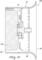
- Fig. 10 illustrates a motor cooling assembly 100.
- the motor cooling assembly 100 comprises the axial flow fan 10.
- the axial flow fan 10 in encompassed in a known fan guard 50.
- the motor cooling assembly 100 comprises the fan guard 50.
- the fan guard 50 encompasses a known axial flown fan 10.
- the motor cooling assembly 100 comprises the axial flow fan 10 and the fan guard 50.
- the axial flow fan 10 is positioned in the conduit 60.
- the axial flow fan 10 is positioned between the first and the second aperture 56, 58.
- the axial flow fan 10 is positioned in the conduit 60 between the grid cover 54 and the second aperture 58.
- the axial flow fan 10 is positioned to draw air into the conduit 60 from the first aperture 56.
- the fan assembly 100 further comprises a motor 102.
- the axial flow fan 10 is mounted to the motor 102.
- the motor is an electric motor.
- the electric motor may be provided with a variable frequency drive.
- This disclosure describes an axial flow fan 10 and a fan guard 50.
- the axial flow fan 10 having blades 16 that are configured to reduce turbulence in the flow of air.
- the reduction of turbulence enables for a reduction of sound being emitted from the cooling system.
- the fan guard 50 has a constriction section that enables an increase of the flow rate between the first and the second apertures. The increase in flow rate is coupled with the reduction in turbulence. Head losses is minimized in the fan guard 50 thereby reducing energy losses.
- the cover 54 of the fan guard 50 has a grid with air flow openings 64 that are aligned with the rotation of the air flow generated by the axial flow fan 10.
Landscapes
- Engineering & Computer Science (AREA)
- Power Engineering (AREA)
- Mechanical Engineering (AREA)
- General Engineering & Computer Science (AREA)
- Physics & Mathematics (AREA)
- Fluid Mechanics (AREA)
- Structures Of Non-Positive Displacement Pumps (AREA)
Abstract
Description
- This disclosure relates generally to the field of cooling systems for electric motors; particularly to the field of air cooling systems for electric motors; and more particularly, to the field of attenuation of emitted sound and reduction of power consumed during operation of the electric motor.
- Electric motors may generate large amounts of heat as a result of the electromagnetic fields therein. The internal heat build-up may significantly reduce the efficiency of the motor, particularly in high-density power applications. Increase in heat may result in an increase in electrical resistance through the motor windings associated as temperatures rise. Thus, dissipation of heat is required for efficient operation of the motor.
- Generally, air cooling systems are known for the dissipation of heat generated by electric motors. The air cooling systems comprise an axial flow fan and a fan guard that encloses the fan. The cooling system may be configured to reduce air flow turbulence so as to provide sound attenuation and reduction of power consumption.
- The present disclosure is directed, at least in part, to improving or overcoming one or more aspects of the prior art system.
- In a first aspect, the present disclosure describes a fan guard for a motor cooling system. The fan guard comprises a shroud having a conduit extending between a first aperture and a second aperture, the shroud having a constricting section configured to restrict airflow moving from the first aperture to the second aperture. The fan guard fan provides for an increase in captured mass flow rate. The increased in mass flow rate provides for motor cooling.
- In a second aspect, the present disclosure describes an axial flow fan for a motor cooling system. The axial flow fan comprises a hub having a rotational axis; a plurality of blades extending radially from the hub, each blade having a leading edge and a trailing edge wherein each blade has at least one flow element for reducing turbulence of air flow. The axial flow fan provides for a reduction in power consumption and a reduction in turbulence of the passing air flow. The reduction in turbulence enables a lowering of the noise level.
- In a third aspect, the present disclosure describes a motor cooling system. The motor cooling system comprises an axial flow fan and/ or a fan guard.
- The foregoing and other features and advantages of the present disclosure will be more fully understood from the following description of various embodiments, when read together with the accompanying drawings, in which:
-
Fig. 1A is a plan view of an axial flow fan, in the first embodiment, according to the present disclosure; -
Fig. 1B is an isometric view of the axial flow fan ofFig. 1A ; -
Fig. 1C is a side view of the axial flow fan ofFig. 1A ; -
Fig. 2A is a plan view of an axial flow fan, in the second embodiment, according to the present disclosure; -
Fig. 2B is an isometric view of the axial flow fan ofFig. 2A ; -
Fig. 2C is a side view of the axial flow fan ofFig. 2A ; -
Fig. 3A is a plan view of an axial flow fan, in the third embodiment, according to the present disclosure; -
Fig. 3B is an isometric view of the axial flow fan ofFig. 3A ; -
Fig. 3C is a side view of the axial flow fan ofFig. 3A ; -
Fig. 4A is a plan view of an axial flow fan, in the fourth embodiment, according to the present disclosure; -
Fig. 4B is an isometric view of the axial flow fan ofFig. 4A ; -
Fig. 4C is a side view of the axial flow fan ofFig. 4A ; -
Fig. 5A is a plan view of an axial flow fan, in the fifth embodiment, according to the present disclosure; -
Fig. 5B is an isometric view of the axial flow fan ofFig. 5A ; -
Fig. 5C is a side view of the axial flow fan ofFig. 5A ; -
Fig. 6A is an isometric view of a fan guard, in the first embodiment, according to the present disclosure; -
Fig. 6B is a cross-sectional view of the fan guard ofFig. 6A ; -
Fig. 7A is an isometric view of a fan guard, in the second embodiment, according to the present disclosure; -
Fig. 7B is a cross-sectional view of the fan guard ofFig. 7A ; -
Fig. 8A is an isometric view of a fan guard, in the third embodiment, according to the present disclosure; -
Fig. 8B is a cross-sectional view of the fan guard ofFig. 8A ; -
Fig. 9A is an isometric view of a fan guard, in the fourth embodiment, according to the present disclosure; -
Fig. 9B is a cross-sectional view of the fan guard ofFig. 9A ; and -
Fig. 10 is a schematic view of a motor cooling system according to the present disclosure. - This disclosure generally relates to an axial fan configured to reduce air flow turbulence, a fan shroud configured to increase speed of air flow and a cooling assembly with the fan positioned in the fan shroud.
-
Figs. 1 to 5 showaxial flow fans 10 in specific embodiments. Theaxial flow fan 10 has ahub 12 and a plurality ofblades 16. Thehub 12 is circular and has a rotationalaxis A. Hub 12 has afront portion 14, arear portion 32 and aside portion 15. - The plurality of
blades 16 extend radially from thehub 12. The plurality ofblades 16 are arranged on theside portion 15 of thehub 12. The plurality ofblades 16 mutually diverge from thehub 12. The plurality ofblades 16 are mutually angularly separated along theside portion 15. The plurality ofblades 16 are substantially linear. - Each
blade 16 is axially elongated along a longitudinal axis B. Eachblade 16 has aleading edge 18 and a trailingedge 20. The leadingedge 18 is inclined relative to the trailingedge 20. Eachblade 16 has a firstflow guide face 22 and a secondguide flow face 24. The firstflow guide face 22 and the second guide flow face 24 connect theleading edge 18 to the trailingedge 20. The firstflow guide face 22 is convex. The second guide flow face 24 is planar. In an alternate embodiment, second guide flow face 24 has a concave curvature. In a further embodiment, second guide flow face 24 has a convex curvature. Eachblade 16 has afree end 26 and acoupling end 28. Thecoupling end 28 is connected to thehub 12. Each blade is angled relative to the plane of rotation of thehub 12. Eachblade 16 has at least oneflow element -
Figs. 1A-1C illustrates a first embodiment of thefan 10. Thefan 10 has ahub 12 with a forward projectingfront portion 14. In an embodiment, thefront portion 14 is shaped as a truncated cone. Therear portion 32 has a coupling means 34 for coupling to a rotor shaft or to a motor. Thefree end 26 of each blade has a convex curvature. Eachblade 16 decreases in width from thecoupling end 28 to thefree end 26. The firstflow guide face 22 and the second guide flow face 24 each decrease in width from thecoupling end 28 to thefree end 26. In an embodiment, the length of theblade 16 from thecoupling end 28 to thefree end 26 is greater than the diameter of thehub 14. - The cross-section of each
blade 16 is shaped as an airfoil. Theblade 16 is slightly truncated on the leadingedge 18. The firstflow guide face 22 and the second guide flow face 24 are contiguous at the trailingedge 20. The firstflow guide face 22 is spaced from the second guide flow face 24 at the trailingedge 20. The transverse height of the leadingedge 18 is greater than the transverse height of the trailingedge 20 - The at least one
flow element 130 is positioned at theleading edge 18. The at least oneflow element 130 is a plurality ofcrests 130. The plurality ofcrests 130 project from theblade 16. The plurality ofcrests 130 project from theblade 10 in a direction substantially transverse to axial extension of theblade 16. The plurality ofcrests 130 project from theblade 16 in a direction substantially transverse to the longitudinal axis B. The plurality ofcrests 130 are arranged in a row. In an embodiment, the plurality ofcrests 130 are mutually spaced. A plurality oftroughs 132 are interposed between the plurality ofcrests 130. In a further embodiment, the depth of eachtrough 132 reaches the level of the leadingedge 18 not having thecrests 130. In an embodiment, eachtrough 132 may be mutually aligned so as to define theleading edge 18 or a portion thereof. In an embodiment, the plurality ofcrests 130 are identical. In an alternate embodiment, thecrests 130 are varied. Thecrests 130 may be smaller from thecoupling end 28 to thefree end 26. Thetroughs 132 may be wider from thecoupling end 28 to thefree end 26. Thetroughs 132 may increase in depth from thecoupling end 28 to thefree end 26. - In an embodiment, the plurality of
crests 130 are positioned adjacent thefree end 26 and spaced from thecoupling end 28 of theblade 16. The leadingedge 18 is linear from the plurality ofcrests 130 to thecoupling end 28. In a further embodiment, the plurality ofcrests 130 are positioned adjacent thecoupling end 28 and spaced from thefree end 26. The leadingedge 18 is linear from thefree end 26 to the plurality ofcrests 130. In yet a further embodiment, the plurality ofcrests 130 are spaced from couplingend 28 and spaced from thefree end 26. The leadingedge 18 is linear from the plurality ofcrests 130 to thecoupling end 28 and to thefree end 26. - In an embodiment, each
crest 130 extends transversely across the leadingedge 18 from the first flow guide face 22 to the secondguide flow face 24. In alternate embodiment, eachcrest 130 partially extends transversely on the leadingedge 18 from the first flow guide face 22 towards the secondguide flow face 24. In a further alternate embodiment, eachcrest 130 partially extends transversely on the leadingedge 18 from the second guide flow face 24 towards the firstflow guide face 22. In a further embodiment, eachcrest 130 is positioned on the leadingedge 18 at the interface of the firstflow guide face 22 and the leadingedge 18. In yet a further embodiment, eachcrest 130 is positioned on the leadingedge 18 at the interface of the secondflow guide face 24 and the leadingedge 18. - In an embodiment, each
crest 130 has a uniform thickness from the firstflow guide face 22 and the second guide flow face 24 to apeak 131 of thecrest 130. In an alternate embodiment, eachcrest 130 has an increasing thickness from the firstflow guide face 22 and the second guide flow face 24 to thepeak 131 of thecrest 130. In a further alternate embodiment, eachcrest 130 has a decreasing thickness from the firstflow guide face 22 and the second guide flow face 24 to thepeak 131 of thecrest 130. In an embodiment, thepeaks 131 of eachcrest 130 may be mutually equal in relation to the thickness and height. -
Figs. 2A-2C illustrates a second embodiment of thefan 10. Thefan 10 has ahub 12 with a forward projectingfront portion 14. Theforward portion 14 is shaped as a truncated cone. Therear portion 32 has a coupling means 34 for coupling to a rotor shaft or a motor. Thefree end 26 of each blade has a convex curvature. Thefree end 26 is concentric with theside portion 15 of thehub 12. Eachblade 16 has a substantially constant width from thecoupling end 28 to thefree end 26. The leadingedge 18 is substantially parallel to the trailingedge 20. The firstflow guide face 22 and the second guide flow face 24 are each substantially constant in width from thecoupling end 28 to thefree end 26. In an embodiment, the length of theblade 16 from thecoupling end 28 to thefree end 26 has a greater magnitude than the diameter of thehub 12. - The cross-section of each
blade 16 is shaped as an airfoil. The firstflow guide face 22 and the second guide flow face 24 are contiguous at theleading edge 18. The firstflow guide face 22 and the second guide flow face 24 are contiguous at the trailingedge 20. - The at least one
flow element 230 is positioned at the trailingedge 20. The at least oneflow element 230 areteeth 230. Theteeth 230 project from theblade 16. Theteeth 230 project from theblade 16 in a direction substantially transverse to axial extension of theblade 16. The free ends 231 of eachtooth 230 lie on a plane that is parallel to the leadingedge 18. In an embodiment, the tips of eachfree end 231 may be mutually aligned so as to define the trailingedge 20 or a portion thereof. Theteeth 230 project from theblade 16 in a direction substantially transverse to the longitudinal axis B. The teeth are arranged in a row. In an embodiment, theteeth 230 are mutually spaced. A plurality oftroughs 232 are interposed between theteeth 230. In a further embodiment, the depth of eachtrough 232 reaches the level of the trailingedge 20 not having theteeth 230. In an embodiment, theteeth 230 are identical. - In an embodiment, the depth of the
troughs 232 may vary from thecoupling end 28 to thefree end 26. The depth of thetroughs 232 may increase from thecoupling end 28 to thefree end 26. In an further embodiment, the spacing between each pair ofteeth 230 may vary. The spacing between each pair ofteeth 230 may increase from thecoupling end 28 to thefree end 26. Alternatively, the spacing between each pair ofteeth 230 may decrease from thecoupling end 28 to thefree end 26. - In an embodiment, the row of the
teeth 230 extend from thefree end 26 to thecoupling end 28. In alternate embodiment, the row ofteeth 230 are positioned adjacent thefree end 26 and spaced from thecoupling end 28 of theblade 16. The trailingedge 20 is linear from the row ofteeth 230 to thecoupling end 28. In a further embodiment, the row ofteeth 230 are positioned adjacent thecoupling end 28 and spaced from thefree end 26. The trailingedge 20 is linear from thefree end 26 to the row ofteeth 230. In yet a further embodiment, therow teeth 230 are spaced from couplingend 28 and spaced from thefree end 26. The trailingedge 20 is linear from the row ofteeth 230 to thecoupling end 28 and from the row ofteeth 230 to thefree end 26. - The
free end 231 of eachtooth 230 is rounded. Thesides 233 of eachtooth 230 may be mutually parallel. The width of eachtooth 230 may be substantially constant from the firstflow guide face 22 and the second guide flow face 24 to thefree end 231. In an embodiment, the width of eachtooth 230 may substantially decrease from the firstflow guide face 22 and the second guide flow face 24 to thefree end 231. In an embodiment, eachtooth 230 has a decreasing thickness from the firstflow guide face 22 and the second guide flow face 24 to thefree end 231. In an alternate embodiment, eachtooth 230 has a uniform thickness from the firstflow guide face 22 and the second guide flow face 24 to thefree end 231. -
Figs. 3A-3C illustrates a third embodiment of thefan 10. Thefan 10 has ahub 12 with a forward projectingfront portion 14. Theforward portion 14 is shaped as a truncated cone. Therear portion 32 has a coupling means 34 for coupling to a rotor shaft or a motor. Thefree end 26 of each blade has a convex curvature. Thefree end 26 is concentric with theside portion 15 of thehub 14. Eachblade 16 has a substantially constant width from thecoupling end 28 to thefree end 26. The leadingedge 18 is substantially parallel to the trailingedge 20. The firstflow guide face 22 and the second guide flow face 24 are each substantially constant in width from thecoupling end 28 to thefree end 26. In an embodiment, the length of theblade 16 from thecoupling end 28 to thefree end 26 has a lesser magnitude than the diameter of thehub 12. - The cross-section of each
blade 16 is shaped as an airfoil. The firstflow guide face 22 and the second guide flow face 24 are contiguous at theleading edge 18. The firstflow guide face 22 and the second guide flow face 24 are contiguous at the trailingedge 20. - The at least one
flow element 330 is positioned at the trailingedge 20. The at least oneflow element 330 areteeth 330. Theteeth 330 project from theblade 16. Theteeth 330 project from theblade 16 in a direction substantially transverse to axial extension of theblade 16. The free ends 331 of eachtooth 330 lie on a plane that is parallel to the leadingedge 18. In an embodiment, the tips of each free end 331 may be mutually aligned so as to define the trailingedge 20 or a portion thereof. Theteeth 330 project from theblade 16 in a direction substantially transverse to the longitudinal axis B. Theteeth 330 are arranged in a row. In an embodiment, theteeth 330 are mutually spaced. A plurality oftroughs 332 are interposed between theteeth 330. In a further embodiment, the depth of eachtrough 332 reaches the level of the trailingedge 20 not having theteeth 330. In an embodiment, theteeth 330 are identical. - In an embodiment, the
teeth 330 extend from thefree end 26 to thecoupling end 28. In alternate embodiment, theteeth 330 are positioned adjacent thefree end 26 and spaced from thecoupling end 28 of theblade 16. The trailingedge 20 is linear from the row ofteeth 330 to thecoupling end 28. In a further embodiment, theteeth 330 are positioned adjacent thecoupling end 28 and spaced from thefree end 26. The trailingedge 20 is linear from thefree end 26 to the row ofteeth 330. In yet a further embodiment, theteeth 330 are spaced from couplingend 28 and spaced from thefree end 26. The trailingedge 20 is linear from the row ofteeth 330 to thecoupling end 28 and from the row ofteeth 330 to thefree end 26. - The free end 331 of each
tooth 330 is pointed. In an embodiment, the free end 331 of eachtooth 330 is rounded. Thesides 233 of eachtooth 230 may be mutually inclined. The width of eachtooth 330 may decrease from the firstflow guide face 22 and the second guide flow face 24 to the free end 331. In an embodiment, eachtooth 330 has a decreasing thickness from the firstflow guide face 22 and the second guide flow face 24 to the free end 331. In an alternate embodiment, eachtooth 330 has a uniform thickness from the firstflow guide face 22 and the second guide flow face 24 to the free end 331. -
Figs. 4A-4C illustrates a fourth embodiment of thefan 10. Thefan 10 has ahub 12 with afront portion 14 having acavity 13. Thecavity 13 is enclosed by theside portion 15. Theforward portion 14 has a connectingmeans 17. The connecting means 17 enables the fan to be connected to the motor shaft (not shown). The connecting means 17 extends centrally and is concentric with theside portion 15. Therear portion 32 has a coupling means 34 for coupling to a rotor shaft or a motor. - The
free end 26 of each blade has a convex curvature. Thefree end 26 is concentric with theside portion 15 of thehub 14. Eachblade 16 has a substantially constant width from thecoupling end 28 to thefree end 26. The leadingedge 18 is substantially parallel to the trailingedge 20. The firstflow guide face 22 and the second guide flow face 24 are each substantially constant in width from thecoupling end 28 to thefree end 26. In an embodiment, the length of theblade 16 from thecoupling end 28 to thefree end 26 has a greater magnitude than the diameter of thehub 14. In an embodiment, thecoupling end 28 of eachblade 16 has areinforcement 29 to strengthen the coupling of theblade 16 to thehub 12. - The cross-section of each
blade 16 is shaped as an airfoil. The firstflow guide face 22 and the second guide flow face 24 are contiguous at theleading edge 18. The firstflow guide face 22 and the second guide flow face 24 are contiguous at the trailingedge 20. - The at least one
flow element 430 is positioned at the trailingedge 20. The at least oneflow element 430 areteeth 430. Theteeth 430 project from theblade 16. Theteeth 430 project from theblade 16 in a direction substantially transverse to axial extension of theblade 16. The free ends 431 of eachtooth 430 lie on a plane that is parallel to the leadingedge 18. In an embodiment, the tips of eachfree end 431 may be mutually aligned so as to define the trailingedge 20 or a portion thereof. Theteeth 430 project from theblade 16 in a direction substantially transverse to the longitudinal axis B. Theteeth 430 are arranged in a row. In an embodiment, theteeth 430 are mutually spaced. A plurality of troughs 432 are interposed between theteeth 430. In an embodiment, theteeth 430 are identical. - In an embodiment, the depth of the troughs 432 may vary from the
coupling end 28 to thefree end 26. The depth of the troughs 432 may increase from thecoupling end 28 to thefree end 26. In an further embodiment, the spacing between each pair ofteeth 430 may vary. The spacing between each pair ofteeth 430 may increase from thecoupling end 28 to thefree end 26. Alternatively, the spacing between each pair ofteeth 430 may decrease from thecoupling end 28 to thefree end 26. - In an embodiment, the
teeth 430 are positioned adjacent thefree end 26 and spaced from thecoupling end 28 of theblade 16. The trailingedge 20 is linear from the row ofteeth 430 to thecoupling end 28. In alternate embodiment, theteeth 430 extend from thefree end 26 to thecoupling end 28. In a further embodiment, theteeth 430 are positioned adjacent thecoupling end 28 and spaced from thefree end 26. The trailingedge 20 is linear from thefree end 26 to the row ofteeth 430. In yet a further embodiment, theteeth 430 are spaced from couplingend 28 and spaced from thefree end 26. The trailingedge 20 is linear from the row ofteeth 430 to thecoupling end 28 and to thefree end 26. - The
free end 431 of eachtooth 430 is pointed. In an embodiment, thefree end 431 of eachtooth 430 is rounded. Thesides 433 of eachtooth 430 may be mutually inclined. The width of eachtooth 430 may decrease from the firstflow guide face 22 and the second guide flow face 24 to thefree end 431. In an embodiment, the width of eachtooth 430 may substantially decrease from the firstflow guide face 22 and the second guide flow face 24 to thefree end 431. In an embodiment, eachtooth 430 has a decreasing thickness from the firstflow guide face 22 and the second guide flow face 24 to thefree end 431. In an alternate embodiment, eachtooth 430 has a uniform thickness from theblade 16 to thefree end 431. -
Figs. 5A-5C illustrates a fifth embodiment of thefan 10. Thefan 10 has ahub 12 with a forward projectingfront portion 14. Theforward portion 14 is shaped as a truncated cone. Therear portion 32 has a coupling means 34 for coupling to a rotor shaft or a motor. Thefree end 26 of each blade has a convex curvature. Thefree end 26 is concentric with theside portion 15 of thehub 14. Eachblade 16 has a substantially constant width from thecoupling end 28 to thefree end 26. The leadingedge 18 is substantially parallel to the trailingedge 20. The firstflow guide face 22 and the second guide flow face 24 are each substantially constant in width from thecoupling end 28 to thefree end 26. In an embodiment, the length of theblade 16 from thecoupling end 28 to thefree end 26 has a greater magnitude than the diameter of thehub 14. - The cross-section of each
blade 16 is shaped as an airfoil. The firstflow guide face 22 and the second guide flow face 24 are contiguous at theleading edge 18. The firstflow guide face 22 and the second guide flow face 24 are contiguous at the trailingedge 20. - The at least one
flow element 530 extends transversely across theblade 16. The at least oneflow element 530 is arib 530 extending transversely across eachblade 16.Rib 530 is a raised structure positioned on theblade 16. -
Rib 530 extends substantially perpendicular to the longitudinal axis B. Therib 530 encircles theblade 16. Therib 530 extends across the firstflow guide face 22 and substantially extends transversely on the firstflow guide face 22.Rib 530 follows convex curvature of the firstflow guide face 22. Therib 530 extends across the secondguide flow face 24 and substantially extends transversely on the secondguide flow face 24.Rib 530 follows the planar form of the secondflow guide face 24. In an embodiment,rib 530 follows concave curvature of the secondguide flow face 24. -
Rib 530 extends across the leadingedge 18. Rib is curved at theleading edge 18.Rib 530 extends across the trailingedge 20. In an embodiment,rib 530 is linear at the trailingedge 20. In alternate embodiment,rib 530 is curved at the trailingedge 20 - In an embodiment, the
blade 16 has tworibs 530. Afirst rib 530 is spaced from asecond rib 530. Thefirst rib 530 is positioned proximate to theside portion 15 and distal to thefree end 26. Thesecond rib 530 is positioned distal to theside portion 15 and proximate to thefree end 26. In an alternate embodiment, the blade has asingle rib 530. Therib 530 is positioned centrally on theblade 16. The rib is 530 equidistant from theside portion 15 and thefree end 26. - The features of the specific embodiments of the
fans 10 may be combined. In particular, thefan 10 may have a combination of theflow elements blades 16. The plurality ofcrests 130 may be combined with therib 530. The plurality ofcrests 130 may be combined with one of theteeth crests 130 may be combined with therib 530 and one of theteeth rib 530 may be combined with one of theteeth -
Figs. 6 to 9 show fan guard 50 in specific embodiments. Thefan guard 50 is configured to accommodate thefan 10. Thefan guard 50 has ashroud 52 and agrid cover 54.Shroud 52 enables air to be channelled therethrough. Theshroud 52 is elongated. In an embodiment, theshroud 52 is cylindrical.Shroud 52 has afirst aperture 56 and asecond aperture 58. In an embodiment, air may enter into theshroud 52 through thefirst aperture 56 and exit theshroud 52 through thesecond aperture 58. In an alternate embodiment, air may enter into thebody 52 through thesecond aperture 58 and exit thebody 52 through thefirst aperture 56.Shroud 52 has anexternal wall 61 and aninternal wall 63. Theinternal wall 63 is concentric to theexternal wall 61. -
Shroud 52 has aconduit 60. Theconduit 60 is defined by aninternal wall 63 of theshroud 52.Conduit 60 extends between thefirst aperture 56 and thesecond aperture 58. In an embodiment,conduit 60 has a circular cross section. Theshroud 52 has a constrictingsection section first aperture 56 to thesecond aperture 58. In an alternate embodiment, the constrictingsection second aperture 58 to thefirst aperture 56 - In an embodiment, the constricting
section conduit 60. In an alternative embodiment, the constrictingsection conduit 60. - The
grid cover 54 is positioned in theshroud 52. In an embodiment, thegrid cover 54 is positioned between the first andsecond apertures grid cover 54 hasair flow openings 64 for flow of air into theshroud 52. In an embodiment, theair flow openings 64 have a H equal to, or below, the limit imposed by Standard(s)-IEC 60335-1:2001. Thegrid cover 54 has anose 66 for providing a spacer for thefan 10. Thenose 66 is positioned in the center of thegrid cover 54. -
Figs. 6A - 6B illustrate a first embodiment of thefan guard 50.Constricting section 162 is positioned in theconduit 60.Constricting section 162 is anannular protuberance 63 configured to initially decrease the diameter of theconduit 60 and subsequently increase the diameter of theconduit 60. The protuberance may be hump shaped. The protruberance is a reverse semi-airfoil. The constrictingsection 162 projects into theconduit 60. In an embodiment, the constrictingsection 162 is a projection of theinternal wall 63 of theshroud 52 into theconduit 60. In an alternate embodiment, the constrictingsection 162 is a body that is mounted to theinternal wall 63 of theshroud 52. - The constricting
section 162 has afirst portion 68 and asecond portion 70. The first andsecond portions first portion 68 has an increasingradial length 65. Thefirst portion 68 increases inradial length 65 from afirst end 67 to an apex 71. Thesecond portion 70 has a decreasingradial length 65. Thesecond portion 70 decreases inradial length 65 from the apex 71 to asecond end 69. Theradial length 65 is the distance from theinternal wall 63 to theexternal wall 61. In the embodiment of a mounted constrictingsection 162 the radial length is a distance from theexternal wall 61 to the surface of the mounted constrictingsection 162 projecting into theconduit 60. - With reference to the airflow path from the
first aperture 56 to thesecond aperture 58, theconduit 60 decreases in diameter along thefirst portion 68 from thefirst end 67 to the apex 71 of the constrictingsection 162. Theconduit 60 increases in diameter along thesecond portion 68 from the apex 71 to thesecond end 69 of the constrictingsection 162. - In an embodiment, the constricting
section 162 is positioned between thefirst aperture 56 and thesecond aperture 58. The constrictingsection 162 may be spaced from thefirst aperture 56 and thesecond aperture 58. The constrictingsection 162 may be positioned such that the first or thesecond end second aperture first aperture 56 has substantially the same diameter relative to the diameter of thesecond aperture 58. - In an embodiment, the constricting
section 162 is positioned between thegrid cover 54 and thesecond aperture 58. Thegrid cover 54 is positioned at thefirst aperture 56. Thefirst end 67 of the constrictingsection 162 is spaced from thefirst aperture 56. Thesecond end 69 of the constrictingsection 162 is positioned at thesecond aperture 58. In an alternate embodiment, the constrictingsection 162 is positioned between thegrid cover 54 and thefirst aperture 56. Thefirst end 67 of the constrictingsection 162 is positioned at thefirst aperture 56. - The
first portion 68 has a reduced axial length relative to thesecond portion 70 with respect to the longitudinal axis of theshroud 52. Thefirst portion 68 has a higher degree of curvature relative to thesecond portion 70. The increased curvature serves to generate a depression in the area of thesecond portion 70, having the lesser curvature, so as increase suction in theshroud 52. - In an embodiment, at the second portion, the
internal wall 63 is inclined relative to theexternal wall 61 by an angle of about 5 degrees. The inclination angle promote pressure recovery and avoid separation of air flow. -
Figs. 7A - 7B illustrate a second embodiment of thefan guard 50.Constricting section 262 is positioned in theconduit 60. The constrictingsection 262 is positioned adjacent thefirst aperture 56.Constricting section 262 extends from thefirst aperture 56 to an end of theinternal wall 63.Constricting section 262 is an annularinclined surface 261 configured to decrease the diameter of theconduit 60 along the constrictingsection 262 up to a constant diameter. Theconduit 60 has a constant diameter along theinternal wall 63. In an embodiment, the constrictingsection 262 is contiguous with thefirst aperture 56. Thefirst aperture 56 has substantially the same diameter relative to the diameter of thesecond aperture 58. - The annular
inclined surface 261 of the constrictingsection 262 is inclined relative to theinternal wall 63 of theshroud 52. The annularinclined surface 261 constrictingsection 262 is inclined relative to theexternal wall 61. The constrictingsection 262 has an increasingradial length 65a from thefirst aperture 56 to aconstant radial length 65b. The constrictingsection 262 has an increasingradial length 65 from thefirst aperture 56 to theinternal wall 63. Theradial length 65 along theinternal wall 63 is substantially constant. With reference to the airflow path from thefirst aperture 56 to thesecond aperture 58, theconduit 60 decreases in diameter along the constrictingsection 262 from thefirst aperture 56 to theinternal wall 63. - In an embodiment, the
grid cover 54 is interposed between theinternal wall 63 and the constrictingsection 262. The constrictingsection 262 is positioned between thefirst aperture 56 and thegrid cover 54. The constrictingsection 262 has an increasingradial length 65 from thefirst aperture 56 to thegrid cover 54. Theconduit 60 decreases in diameter along the constrictingsection 262 from thefirst aperture 56 to thegrid cover 54. Theconduit 60 has a substantially constant diameter from thegrid cover 54 to thesecond aperture 58. -
Figs. 8A - 8B illustrate a third embodiment of thefan guard 50.Constricting section 362 is positioned in theconduit 60. The constrictingsection 362 is positioned adjacent thefirst aperture 56.Constricting section 362 extends from thefirst aperture 56 to theinternal wall 63.Constricting section 362 is an annularcurved surface 361 configured to decrease the diameter of theconduit 60 along the constrictingsection 362 up to a constant diameter. Theconduit 60 has a constant diameter along theinternal wall 63. In an embodiment, the constrictingsection 362 is contiguous with thefirst aperture 56. Thefirst aperture 56 has substantially the same diameter relative to the diameter of thesecond aperture 58. - The constricting
section 362 is an annularcurved surface 361 with a convex curvature. The annularcurved surface 361 faces into theconduit 60. The constrictingsection 362 has an increasingradial length 65a from thefirst aperture 56 to aconstant radial length 65b. The constrictingsection 362 has an increasingradial length 65 from thefirst aperture 56 to theinternal wall 63. Theradial length 65 along theinternal wall 63 is substantially constant. With reference to the airflow path from thefirst aperture 56 to thesecond aperture 58, theconduit 60 decreases in diameter along the constrictingsection 362 from thefirst aperture 56 to theinternal wall 63. - In an embodiment, the
grid cover 54 is interposed between theinternal wall 63 and the constrictingsection 362. The constrictingsection 362 is positioned between thefirst aperture 56 and thegrid cover 54. The constrictingsection 362 has an increasingradial length 65 from thefirst aperture 56 to thegrid cover 54. Theconduit 60 decreases in diameter along the constrictingsection 362 from thefirst aperture 56 to thegrid cover 54. Theconduit 60 has a substantially constant diameter from thegrid cover 54 to thesecond aperture 58. -
Figs. 9A - 9B illustrate a fourth embodiment of thefan guard 50. The constrictingsection 462 is an extension of theshroud 52. The constrictingsection 462 is an outwardly flared extension.Constricting section 462 has an internal flaredsurface 461 and an external flaredsurface 463. The internal flaredsurface 461 and the external flaredsurface 463 are mutually parallel. The constrictingsection 462 has aconstant radial length 65.Constricting section 462 is horn-shaped. -
Constricting section 462 extends from thefirst aperture 56 to an end of theinternal wall 63. Theconduit 60 decreases in diameter from thefirst aperture 56 along the constrictingsection 462 up to a constant diameter. Theconduit 60 has a constant diameter along theinternal wall 63. In an embodiment, the constrictingsection 462 is contiguous with thefirst aperture 56. Thefirst aperture 56 has a greater diameter relative to the diameter of thesecond aperture 58.First aperture 56 has a greater diameter relative to the diameter of theconduit 60 along theinternal wall 63. With reference to the airflow path from thefirst aperture 56 to thesecond aperture 58, theconduit 60 decreases in diameter along the constrictingsection 462 from thefirst aperture 56 to theinternal wall 63. - In an embodiment, the
grid cover 54 is interposed between theinternal wall 63 and the constrictingsection 462. The constrictingsection 462 is positioned between thefirst aperture 56 and thegrid cover 54. The constrictingsection 462 has aconstant radial length 65 from thefirst aperture 56 to thegrid cover 54. Theconduit 60 decreases in diameter along the constrictingsection 462 from thefirst aperture 56 to thegrid cover 54. Theconduit 60 has a substantially constant diameter from thegrid cover 54 to thesecond aperture 58. -
Fig. 10 illustrates amotor cooling assembly 100. Themotor cooling assembly 100 comprises theaxial flow fan 10. Theaxial flow fan 10 in encompassed in a knownfan guard 50. Themotor cooling assembly 100 comprises thefan guard 50. Thefan guard 50 encompasses a known axial flownfan 10. - The
motor cooling assembly 100 comprises theaxial flow fan 10 and thefan guard 50. Theaxial flow fan 10 is positioned in theconduit 60. Theaxial flow fan 10 is positioned between the first and thesecond aperture axial flow fan 10 is positioned in theconduit 60 between thegrid cover 54 and thesecond aperture 58. Theaxial flow fan 10 is positioned to draw air into theconduit 60 from thefirst aperture 56. Thefan assembly 100 further comprises amotor 102. Theaxial flow fan 10 is mounted to themotor 102. In an embodiment, the motor is an electric motor. The electric motor may be provided with a variable frequency drive. - The skilled person would appreciate that foregoing embodiments may be modified or combined to obtain the
fan 10,fan guard 50 and thefan assembly 100 of the present disclosure. - This disclosure describes an
axial flow fan 10 and afan guard 50. Theaxial flow fan 10 havingblades 16 that are configured to reduce turbulence in the flow of air. The reduction of turbulence enables for a reduction of sound being emitted from the cooling system. Thefan guard 50 has a constriction section that enables an increase of the flow rate between the first and the second apertures. The increase in flow rate is coupled with the reduction in turbulence. Head losses is minimized in thefan guard 50 thereby reducing energy losses. - The
cover 54 of thefan guard 50 has a grid withair flow openings 64 that are aligned with the rotation of the air flow generated by theaxial flow fan 10. - Accordingly, this disclosure includes all modifications and equivalents of the subject matter recited in the claims appended hereto as permitted by applicable law. Moreover, any combination of the above-described elements in all possible variations thereof is encompassed by the disclosure unless otherwise indicated herein.
- Where technical features mentioned in any claim are followed by reference signs, the reference signs have been included for the sole purpose of increasing the intelligibility of the claims and accordingly, neither the reference signs nor their absence have any limiting effect on the technical features as described above or on the scope of any claim elements.
- One skilled in the art will realise the disclosure may be embodied in other specific forms without departing from the disclosure or essential characteristics thereof. The foregoing embodiments are therefore to be considered in all respects illustrative rather than limiting of the disclosure described herein. Scope of the invention is thus indicated by the appended claims, rather than the foregoing description, and all changes that come within the meaning and range of equivalence of the claims are therefore intended to be embraced therein.
Claims (15)
- A fan guard (50) for a motor cooling system, the fan guard (50) comprising:
a shroud (52) having a conduit (60) extending between a first aperture (56) and a second aperture (58), the shroud (52) having a constricting section (162, 262, 362, 462) configured to restrict airflow moving from the first aperture (56) to the second aperture (58). - The fan guard (50) of claim 1 wherein the constricting section (162) is positioned in the conduit (60), the constricting section (162) being an annular protuberance having a first portion (68) with an increasing radial length (65) and a second portion (70) with a decreasing radial height (65) wherein the first and second portions are contiguous (68, 70).
- The fan guard (50) of claim 1 wherein the constricting section (262, 362) is positioned in the conduit (60) adjacent the first aperture (56), the constricting section (262, 362) having an increasing radial length (65) from the first aperture (56) to an internal wall (63) of the shroud (52).
- The fan guard (50) of claim 2 wherein the constricting section (262) is an annular inclined surface, the annular inclined surface being inclined relative to the internal wall (63) of the shroud (52).
- The fan guard (50) of claim 3 wherein the constricting section (362) is an annular convex surface, the annular convex surface facing the conduit (60).
- The fan guard (50) of claims 4 or 5 wherein the constricting section (262, 362) is contiguous with the first aperture (56).
- The fan guard (50) of claim 1 wherein the constricting section (462) is an outwardly flared projection extending from the shroud (52).
- An axial flow fan (10) for a motor cooling system, the axial flow fan (10) comprising:a hub (12) having a rotational axis (A);a plurality of blades (16) extending radially from the hub (12), each blade (16) having a leading edge (18) and a trailing edge (20) wherein each blade (16) has at least one flow element (130, 230, 330, 430, 530) for reducing turbulence of air flow.
- The axial flow fan (10) of claim 8 wherein the element (130) is a plurality crests (130) positioned at the leading edge (18).
- The axial flow fan (10) of claims 8 or 9 wherein the flow element (230, 330, 430) is a plurality of teeth positioned at the trailing edge (20).
- The axial flow fan (10) of claims 8, 9 or 10 of wherein the flow element (530) is a rib (530) extending transversely across each blade (16).
- The axial flow fan (10) of claim 11 wherein the rib (530) encircles the blade (16).
- The axial flow fan (10) of claims 11 or 12 wherein the rib (530) is curved at the leading edge (18) and is linear at the trailing edge (20).
- A motor cooling system (100) comprising:an axial flow fan (10) of any one of claims 8 to 13; and/ora fan guard (50) of anyone of claims 1 to 7.
- The motor cooling system (100) wherein the axial flow fan (10) is positioned in the fan guard (50) and wherein the axial flow fan (10) is mounted to a motor.
Priority Applications (2)
| Application Number | Priority Date | Filing Date | Title |
|---|---|---|---|
| EP18181882.4A EP3591238A1 (en) | 2018-07-05 | 2018-07-05 | Axial flow fan and fan guard for a motor cooling assembly |
| PCT/EP2019/068042 WO2020008007A1 (en) | 2018-07-05 | 2019-07-04 | Axial flow fan and fan guard for a motor cooling assembly |
Applications Claiming Priority (1)
| Application Number | Priority Date | Filing Date | Title |
|---|---|---|---|
| EP18181882.4A EP3591238A1 (en) | 2018-07-05 | 2018-07-05 | Axial flow fan and fan guard for a motor cooling assembly |
Publications (1)
| Publication Number | Publication Date |
|---|---|
| EP3591238A1 true EP3591238A1 (en) | 2020-01-08 |
Family
ID=62874634
Family Applications (1)
| Application Number | Title | Priority Date | Filing Date |
|---|---|---|---|
| EP18181882.4A Withdrawn EP3591238A1 (en) | 2018-07-05 | 2018-07-05 | Axial flow fan and fan guard for a motor cooling assembly |
Country Status (2)
| Country | Link |
|---|---|
| EP (1) | EP3591238A1 (en) |
| WO (1) | WO2020008007A1 (en) |
Cited By (1)
| Publication number | Priority date | Publication date | Assignee | Title |
|---|---|---|---|---|
| CN122083025A (en) * | 2026-04-24 | 2026-05-26 | 浙江亿利达风机股份有限公司 | A low-noise axial flow blade with double-stage serrations |
Citations (9)
| Publication number | Priority date | Publication date | Assignee | Title |
|---|---|---|---|---|
| JPS5867999A (en) * | 1981-10-16 | 1983-04-22 | Hitachi Ltd | Moving vane structure in axial flow type fluid machine |
| WO2002053919A1 (en) * | 2000-12-28 | 2002-07-11 | Daikin Industries, Ltd. | Blower, and outdoor unit for air conditioner |
| JP2004068611A (en) * | 2002-08-01 | 2004-03-04 | Suiden Co Ltd | Bellmouth connected with blower wind tunnel part |
| CN102182698A (en) * | 2011-05-27 | 2011-09-14 | 北京精诚博桑科技有限公司 | Efficient long-range and low-noise axial flow fan and spraying device |
| CN102478027A (en) * | 2010-11-22 | 2012-05-30 | 台达电子工业股份有限公司 | Fan assembly and flow passage device thereof |
| CN202391808U (en) * | 2011-12-13 | 2012-08-22 | 广东美的电器股份有限公司 | Low-noise axial flow air wheel |
| WO2013131641A2 (en) * | 2012-03-06 | 2013-09-12 | Ziehl-Abegg Ag | Axial fan |
| CN105736425A (en) * | 2016-04-26 | 2016-07-06 | 浙江理工大学 | Axial flow fan comprising blades with wing-type guide plates and guide blades with bionic tail edges |
| JP2017070337A (en) * | 2015-10-05 | 2017-04-13 | 日立マクセル株式会社 | Blower |
-
2018
- 2018-07-05 EP EP18181882.4A patent/EP3591238A1/en not_active Withdrawn
-
2019
- 2019-07-04 WO PCT/EP2019/068042 patent/WO2020008007A1/en not_active Ceased
Patent Citations (9)
| Publication number | Priority date | Publication date | Assignee | Title |
|---|---|---|---|---|
| JPS5867999A (en) * | 1981-10-16 | 1983-04-22 | Hitachi Ltd | Moving vane structure in axial flow type fluid machine |
| WO2002053919A1 (en) * | 2000-12-28 | 2002-07-11 | Daikin Industries, Ltd. | Blower, and outdoor unit for air conditioner |
| JP2004068611A (en) * | 2002-08-01 | 2004-03-04 | Suiden Co Ltd | Bellmouth connected with blower wind tunnel part |
| CN102478027A (en) * | 2010-11-22 | 2012-05-30 | 台达电子工业股份有限公司 | Fan assembly and flow passage device thereof |
| CN102182698A (en) * | 2011-05-27 | 2011-09-14 | 北京精诚博桑科技有限公司 | Efficient long-range and low-noise axial flow fan and spraying device |
| CN202391808U (en) * | 2011-12-13 | 2012-08-22 | 广东美的电器股份有限公司 | Low-noise axial flow air wheel |
| WO2013131641A2 (en) * | 2012-03-06 | 2013-09-12 | Ziehl-Abegg Ag | Axial fan |
| JP2017070337A (en) * | 2015-10-05 | 2017-04-13 | 日立マクセル株式会社 | Blower |
| CN105736425A (en) * | 2016-04-26 | 2016-07-06 | 浙江理工大学 | Axial flow fan comprising blades with wing-type guide plates and guide blades with bionic tail edges |
Cited By (1)
| Publication number | Priority date | Publication date | Assignee | Title |
|---|---|---|---|---|
| CN122083025A (en) * | 2026-04-24 | 2026-05-26 | 浙江亿利达风机股份有限公司 | A low-noise axial flow blade with double-stage serrations |
Also Published As
| Publication number | Publication date |
|---|---|
| WO2020008007A1 (en) | 2020-01-09 |
Similar Documents
| Publication | Publication Date | Title |
|---|---|---|
| JP5097201B2 (en) | Axial fan assembly | |
| US6435828B1 (en) | Split blade radial fan | |
| EP3808991B1 (en) | Air treatment device, fan and centrifugal impeller thereof | |
| US10935039B2 (en) | Blower impeller for a handheld blower | |
| CN108180154B (en) | Fan ripple support | |
| KR20100096219A (en) | Propeller fan | |
| EP2530331A2 (en) | Axial fan assembly for a vehicle cooling system | |
| EP0848788B1 (en) | A radial fan wheel | |
| EP0168594B1 (en) | Improved axial fan | |
| CN116249838B (en) | propeller fan | |
| CN213953930U (en) | A noise reduction axial fan | |
| WO2020008007A1 (en) | Axial flow fan and fan guard for a motor cooling assembly | |
| JP5978886B2 (en) | Blower | |
| EP0704625B1 (en) | A fan | |
| CN101772651B (en) | Axial flow fan | |
| CN107061357B (en) | Blades, Centrifugal Fan Wheels, Centrifugal Fans and Range Hoods | |
| CN110307178B (en) | Low-noise impeller | |
| WO2021103050A1 (en) | Fan and motor | |
| CN216241482U (en) | Wind wheel and air outlet device | |
| CN212454949U (en) | Impellers, fans and range hoods | |
| CN117419069A (en) | Impellers, fans and range hoods | |
| WO2020124024A1 (en) | Dual stage blower assembly | |
| JP4576304B2 (en) | Propeller fan | |
| RU243173U1 (en) | IMPELLER OF EXPLOSION-PROOF DUCT FAN | |
| KR200248773Y1 (en) | Fan and Shroud Assembly |
Legal Events
| Date | Code | Title | Description |
|---|---|---|---|
| PUAI | Public reference made under article 153(3) epc to a published international application that has entered the european phase |
Free format text: ORIGINAL CODE: 0009012 |
|
| STAA | Information on the status of an ep patent application or granted ep patent |
Free format text: STATUS: THE APPLICATION HAS BEEN PUBLISHED |
|
| AK | Designated contracting states |
Kind code of ref document: A1 Designated state(s): AL AT BE BG CH CY CZ DE DK EE ES FI FR GB GR HR HU IE IS IT LI LT LU LV MC MK MT NL NO PL PT RO RS SE SI SK SM TR |
|
| AX | Request for extension of the european patent |
Extension state: BA ME |
|
| STAA | Information on the status of an ep patent application or granted ep patent |
Free format text: STATUS: REQUEST FOR EXAMINATION WAS MADE |
|
| 17P | Request for examination filed |
Effective date: 20200409 |
|
| RBV | Designated contracting states (corrected) |
Designated state(s): AL AT BE BG CH CY CZ DE DK EE ES FI FR GB GR HR HU IE IS IT LI LT LU LV MC MK MT NL NO PL PT RO RS SE SI SK SM TR |
|
| STAA | Information on the status of an ep patent application or granted ep patent |
Free format text: STATUS: EXAMINATION IS IN PROGRESS |
|
| 17Q | First examination report despatched |
Effective date: 20211124 |
|
| STAA | Information on the status of an ep patent application or granted ep patent |
Free format text: STATUS: THE APPLICATION IS DEEMED TO BE WITHDRAWN |
|
| 18D | Application deemed to be withdrawn |
Effective date: 20231109 |