EP3591216A1 - Runner blade - Google Patents
Runner blade Download PDFInfo
- Publication number
- EP3591216A1 EP3591216A1 EP18305868.4A EP18305868A EP3591216A1 EP 3591216 A1 EP3591216 A1 EP 3591216A1 EP 18305868 A EP18305868 A EP 18305868A EP 3591216 A1 EP3591216 A1 EP 3591216A1
- Authority
- EP
- European Patent Office
- Prior art keywords
- runner
- runner blade
- leading edge
- distance
- concave region
- Prior art date
- Legal status (The legal status is an assumption and is not a legal conclusion. Google has not performed a legal analysis and makes no representation as to the accuracy of the status listed.)
- Withdrawn
Links
- 230000002093 peripheral effect Effects 0.000 claims abstract description 11
- 230000015572 biosynthetic process Effects 0.000 description 2
- XLYOFNOQVPJJNP-UHFFFAOYSA-N water Substances O XLYOFNOQVPJJNP-UHFFFAOYSA-N 0.000 description 2
- 230000003247 decreasing effect Effects 0.000 description 1
Images


Classifications
-
- F—MECHANICAL ENGINEERING; LIGHTING; HEATING; WEAPONS; BLASTING
- F03—MACHINES OR ENGINES FOR LIQUIDS; WIND, SPRING, OR WEIGHT MOTORS; PRODUCING MECHANICAL POWER OR A REACTIVE PROPULSIVE THRUST, NOT OTHERWISE PROVIDED FOR
- F03B—MACHINES OR ENGINES FOR LIQUIDS
- F03B3/00—Machines or engines of reaction type; Parts or details peculiar thereto
- F03B3/12—Blades; Blade-carrying rotors
- F03B3/126—Rotors for essentially axial flow, e.g. for propeller turbines
-
- F—MECHANICAL ENGINEERING; LIGHTING; HEATING; WEAPONS; BLASTING
- F03—MACHINES OR ENGINES FOR LIQUIDS; WIND, SPRING, OR WEIGHT MOTORS; PRODUCING MECHANICAL POWER OR A REACTIVE PROPULSIVE THRUST, NOT OTHERWISE PROVIDED FOR
- F03B—MACHINES OR ENGINES FOR LIQUIDS
- F03B3/00—Machines or engines of reaction type; Parts or details peculiar thereto
- F03B3/12—Blades; Blade-carrying rotors
- F03B3/121—Blades, their form or construction
-
- F—MECHANICAL ENGINEERING; LIGHTING; HEATING; WEAPONS; BLASTING
- F05—INDEXING SCHEMES RELATING TO ENGINES OR PUMPS IN VARIOUS SUBCLASSES OF CLASSES F01-F04
- F05B—INDEXING SCHEME RELATING TO WIND, SPRING, WEIGHT, INERTIA OR LIKE MOTORS, TO MACHINES OR ENGINES FOR LIQUIDS COVERED BY SUBCLASSES F03B, F03D AND F03G
- F05B2250/00—Geometry
- F05B2250/70—Shape
- F05B2250/71—Shape curved
- F05B2250/712—Shape curved concave
-
- F—MECHANICAL ENGINEERING; LIGHTING; HEATING; WEAPONS; BLASTING
- F05—INDEXING SCHEMES RELATING TO ENGINES OR PUMPS IN VARIOUS SUBCLASSES OF CLASSES F01-F04
- F05B—INDEXING SCHEME RELATING TO WIND, SPRING, WEIGHT, INERTIA OR LIKE MOTORS, TO MACHINES OR ENGINES FOR LIQUIDS COVERED BY SUBCLASSES F03B, F03D AND F03G
- F05B2260/00—Function
- F05B2260/96—Preventing, counteracting or reducing vibration or noise
-
- Y—GENERAL TAGGING OF NEW TECHNOLOGICAL DEVELOPMENTS; GENERAL TAGGING OF CROSS-SECTIONAL TECHNOLOGIES SPANNING OVER SEVERAL SECTIONS OF THE IPC; TECHNICAL SUBJECTS COVERED BY FORMER USPC CROSS-REFERENCE ART COLLECTIONS [XRACs] AND DIGESTS
- Y02—TECHNOLOGIES OR APPLICATIONS FOR MITIGATION OR ADAPTATION AGAINST CLIMATE CHANGE
- Y02E—REDUCTION OF GREENHOUSE GAS [GHG] EMISSIONS, RELATED TO ENERGY GENERATION, TRANSMISSION OR DISTRIBUTION
- Y02E10/00—Energy generation through renewable energy sources
- Y02E10/20—Hydro energy
Definitions
- the invention concerns a runner blade.
- the invention concerns a runner blade intended to be implemented in a hydroelectric turbine.
- the runner blade according the present invention is intended to reduce cavitation, especially in the close proximity to the runner hub.
- Hydroelectric turbines used for hydropower generation are generally provided with a runner or a propeller which comprises runner blades connected to a hub rotationally mounted on a rotation shaft.
- a stream of water enters the hydroelectric turbine at high pressure, and exerts a force on the runner blades, which triggers their moving, and consequently the rotation of the runner around the axis of rotation.
- An aim of the invention is thus to propose a runner blade for which cavitation is avoided, or at least limited.
- an aim of the present invention is to propose a runner blade for which cavitation is avoided or at least limited in the close proximity of the hub of the runner.
- a runner blade comprising two opposite faces, said, respectively, pressure face and suction face, connected by a contour, said contour having a hub connecting section opposite to a peripheral section which are connected by two edges said, respectively, leading edge and trailing edge, the suction face is provided with a concave region extending along a radial line of the runner blade, said radial line being a line joining the hub connecting section and the peripheral section and along which the runner blade extend.
- profiles of the concave region taken along concentric paths joining the leading edge and the trailing edge, display a valley surrounded by two peaks said, respectively, leading peak and trailing peak.
- the distance between the leading edge and the leading peak is less than 30% of the distance between the leading edge and the trailing edge.
- the distance between the trailing edge and the trailing peak is less than 30% of the distance between the trailing edge and the leading edge.
- the valley is located at a distance for from the leading edge which in the 40% to 60% range of the distance between the trailing edge and the leading edge.
- the height difference between the two peaks and the valley is below 20%, advantageously below 10%, of the maximum thickness of the runner blade.
- the concave region gets shallower when extending along the radial direction either from the connecting section or the peripheral section.
- the extension of the concave region is less than 25%, advantageously less than 20%, of the total span of the runner blade.
- the runner blade further comprises connection means adapted for connecting the hub connection section of the runner blade to a hub.
- the concave region extends from the connection means.
- the invention also concerns a runner comprising a hub provided with runner blades, advantageously three to six runner blade, according to the present invention.
- the invention also concerns a turbine for hydropower generation comprising the runner according to the present invention.
- the runner blade comprises, on its suction face, a concave region extending along the spanning direction of said runner blade.
- concave region means a region having a gutter shape, in particular a rounded gutter shape.
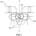
- the figure 1 represents a turbine 100 for hydropower generation provided with a runner 200 mounted on a rotation axis XX'.
- the runner 200 is provided with a plurality of runner blades 300 connected to a hub 400 ( figures 1 and 2 ).
- a runner blade 300 comprises two opposite faces, said, respectively, pressure face 300a and suction face 300b.
- Both faces are connected by a contour having a hub connecting section 310 and a peripheral section 320 which are connected by two edges said, respectively, leading edge 330 and trailing edge 340 ( figures 3a and 3b ).
- Both leading edge 330 and trailing 340 define two specific radial direction along which the runner blade 300 spans.
- the runner blade mean profile defines radial lines along which the runner blade spans. Said radial lines intersect the axis of rotation XX'.
- the runner blade 300 further comprises a concave region 350 (delimited by the dashed lines in figure 3a ).
- the concave region 350 can reflect thickness law variation.
- the thickness law of the runner 300 can display local extrema related to the concave region 350.
- the thickness law is relating to a thickness profile of section of the runner blade taken along a concentric path AA' that will be described later in the description.
- the concave region 350 thus locally induces a pressure increase in its vicinity during rotation of runner, so that cavity bubbles formation is less likely to occur.
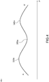
- profiles of the concave region taken along a concentric path AA' joining the leading edge and the trailing edge ( figure 3a , path AA'), display a valley 350a surrounded by two peaks said, respectively, leading peak 330a and trailing peak 340a ( figure 4 ).
- Concentric paths AA' represent concentric camber lines, with respect to the axis of rotation, of the suction face.
- concentric paths AA' and the radial lines form a mesh wherein each radial line extends perpendicularly to the tangent of said concentric lines AA'.
- Peaks and valley are associated with smooth variations of the surface.
- the first and second derivative of the suction face along the concentric path AA' are continuous.
- the distance along the concentric path AA' between the leading edge 330 and the leading peak 330a can be less than 30% of the distance between the leading edge 330 and the trailing edge 340.
- the distance along the concentric path AA' between the trailing edge 340 and the trailing peak 340a can be less than 30% of the distance between the trailing edge 340 and the leading edge 330.
- the valley 350a can be located, along the concentric path AA', at a distance from the leading edge 330 which is in the 40% to 60% range of the distance between the trailing edge and the leading edge.
- the height difference between the two peaks and the valley is below 20%, advantageously below 10%, of the maximum thickness of the runner blade.
- the concave region gets shallower when extending along the radial direction either from the connecting section or the peripheral section.
- the extension of the concave region is less than 25%, advantageously less than 20%, of the total span of the runner blade.
- the runner blade further can comprise connection means adapted for connecting the hub connection section of the runner blade to a hub.
- the concave region extends from the connection means.
Landscapes
- Engineering & Computer Science (AREA)
- Chemical & Material Sciences (AREA)
- Combustion & Propulsion (AREA)
- Mechanical Engineering (AREA)
- General Engineering & Computer Science (AREA)
- Hydraulic Turbines (AREA)
Abstract
The invention concerns a runner blade (300) comprising two opposite faces, said, respectively, pressure face and suction face (300b), connected by a contour, said contour having a hub connecting section (310) opposite to a peripheral section (330) which are connected by two edges said, respectively, leading edge and trailing edge (340), the suction face is provided with a concave region (350) extending radially with respect to the runner blade.
Description
- The invention concerns a runner blade. In particular, the invention concerns a runner blade intended to be implemented in a hydroelectric turbine. The runner blade according the present invention is intended to reduce cavitation, especially in the close proximity to the runner hub.
- Hydroelectric turbines used for hydropower generation are generally provided with a runner or a propeller which comprises runner blades connected to a hub rotationally mounted on a rotation shaft.
- In operation, a stream of water enters the hydroelectric turbine at high pressure, and exerts a force on the runner blades, which triggers their moving, and consequently the rotation of the runner around the axis of rotation.
- During rotation of the runner, a pressure decrease on a suction side face, opposite to the pressure side, of the blades can be observed. As the pressure drops below the vapor pressure of water, cavitation bubbles form and coalesce, which affect the performances of the turbine and then collapse, thus causing vibrations, and damaging of the blades surface.
- For a given runner diameter, in order to prevent, or at least reduce, cavitation bubble formation, increase of the submergence of the turbine may be contemplated. However, this solution which increases considerably the cost is not satisfactory.
- Alternatively, reduction of cavitation can also be achieved by decreasing the hub diameter. This solution is not satisfactory either since it does not let enough room for incorporating blade orientation mechanism as required in Kaplan type runners.
- An aim of the invention is thus to propose a runner blade for which cavitation is avoided, or at least limited.
- In particular, an aim of the present invention is to propose a runner blade for which cavitation is avoided or at least limited in the close proximity of the hub of the runner.
- The aforementioned aims are, at least partly, achieved by a runner blade comprising two opposite faces, said, respectively, pressure face and suction face, connected by a contour, said contour having a hub connecting section opposite to a peripheral section which are connected by two edges said, respectively, leading edge and trailing edge, the suction face is provided with a concave region extending along a radial line of the runner blade, said radial line being a line joining the hub connecting section and the peripheral section and along which the runner blade extend.
- In other words, the concave region extending radially.
- By "extending radially", it is intended an extension along a direction from one of the hub connecting section and the peripheral section toward the other of the hub connecting section and the peripheral section.
- According to a mode of implementation, profiles of the concave region, taken along concentric paths joining the leading edge and the trailing edge, display a valley surrounded by two peaks said, respectively, leading peak and trailing peak.
- According to a mode of implementation, the distance between the leading edge and the leading peak is less than 30% of the distance between the leading edge and the trailing edge.
- According to a mode of implementation, the distance between the trailing edge and the trailing peak is less than 30% of the distance between the trailing edge and the leading edge.
- According to a mode of implementation, the valley is located at a distance for from the leading edge which in the 40% to 60% range of the distance between the trailing edge and the leading edge.
- According to a mode of implementation, the height difference between the two peaks and the valley is below 20%, advantageously below 10%, of the maximum thickness of the runner blade.
- According to a mode of implementation, the concave region gets shallower when extending along the radial direction either from the connecting section or the peripheral section.
- According to a mode of implementation, the extension of the concave region is less than 25%, advantageously less than 20%, of the total span of the runner blade.
- According to a mode of implementation, the runner blade further comprises connection means adapted for connecting the hub connection section of the runner blade to a hub.
- According to a mode of implementation, the concave region extends from the connection means.
- The invention also concerns a runner comprising a hub provided with runner blades, advantageously three to six runner blade, according to the present invention.
- The invention also concerns a turbine for hydropower generation comprising the runner according to the present invention.
- Other characteristics and advantages of the invention will become clear from the description that follows of modes of implementing the runner blade according to the invention, given as non-limiting examples, with reference to the appended drawings in which:
-
Figure 1 is a schematic representation along a longitudinal sectional plan of a turbine provided with runner blades according to the present invention; -
Figure 2 is a schematic representation in perspective of a turbine runner provided with runner blades according to the present invention; -
Figures 3a and 3b are schematic representation in perspective of a runner blade according to the present invention; -
Figure 4 is graphical representation of a suction face profile taken along the concentric path AA', in particular, the vertical axis represents the relative height H (in arbitrary units) as a function of the position P along the concentric path AA' (horizontal axis, in arbitrary units). - Although specifically described with reference to the runner, and notably the runner blades, of a turbine for hydropower generation, other applications of the invention, like boat propulsion propellers, may be contemplated.
- According to the present invention, the runner blade comprises, on its suction face, a concave region extending along the spanning direction of said runner blade. Within the scope of the present invention, concave region means a region having a gutter shape, in particular a rounded gutter shape. When implemented on the blade suction face of a rotating runner, said concave region locally induces an increase of pressure, and as a consequence reduces cavitation bubble growth.
- The invention will now be described in connection with the appended
figures 1 ,2 ,3a, 3b , and4 . - In particular, the
figure 1 represents aturbine 100 for hydropower generation provided with arunner 200 mounted on a rotation axis XX'. - The
runner 200 is provided with a plurality ofrunner blades 300 connected to a hub 400 (figures 1 and2 ). - A
runner blade 300 comprises two opposite faces, said, respectively,pressure face 300a andsuction face 300b. - Both faces are connected by a contour having a
hub connecting section 310 and a peripheral section 320 which are connected by two edges said, respectively, leadingedge 330 and trailing edge 340 (figures 3a and 3b ). - Both leading
edge 330 and trailing 340 define two specific radial direction along which therunner blade 300 spans. In particular, the runner blade mean profile defines radial lines along which the runner blade spans. Said radial lines intersect the axis of rotation XX'. - The
runner blade 300 further comprises a concave region 350 (delimited by the dashed lines infigure 3a ). Theconcave region 350 can reflect thickness law variation. In particular, the thickness law of therunner 300 can display local extrema related to theconcave region 350. The thickness law is relating to a thickness profile of section of the runner blade taken along a concentric path AA' that will be described later in the description. - The
concave region 350 thus locally induces a pressure increase in its vicinity during rotation of runner, so that cavity bubbles formation is less likely to occur. - Advantageously, profiles of the concave region, taken along a concentric path AA' joining the leading edge and the trailing edge (
figure 3a , path AA'), display avalley 350a surrounded by two peaks said, respectively, leadingpeak 330a and trailingpeak 340a (figure 4 ). - Concentric paths AA' represent concentric camber lines, with respect to the axis of rotation, of the suction face. In particular, concentric paths AA' and the radial lines form a mesh wherein each radial line extends perpendicularly to the tangent of said concentric lines AA'.
- Peaks and valley, within the scope of the present invention, are associated with smooth variations of the surface. In other words, the first and second derivative of the suction face along the concentric path AA' are continuous.
- The distance along the concentric path AA' between the leading
edge 330 and the leadingpeak 330a can be less than 30% of the distance between the leadingedge 330 and thetrailing edge 340. - The distance along the concentric path AA' between the
trailing edge 340 and the trailingpeak 340a can be less than 30% of the distance between thetrailing edge 340 and the leadingedge 330. - Furthermore, the
valley 350a can be located, along the concentric path AA', at a distance from the leadingedge 330 which is in the 40% to 60% range of the distance between the trailing edge and the leading edge. - Besides, the height difference between the two peaks and the valley is below 20%, advantageously below 10%, of the maximum thickness of the runner blade.
- The concave region gets shallower when extending along the radial direction either from the connecting section or the peripheral section.
- Advantageously, the extension of the concave region is less than 25%, advantageously less than 20%, of the total span of the runner blade.
- The runner blade further can comprise connection means adapted for connecting the hub connection section of the runner blade to a hub.
- In a preferred embodiment, the concave region extends from the connection means.
Claims (12)
- Runner blade (300) comprising two opposite faces, said, respectively, pressure face (300a) and suction face (300b), connected by a contour, said contour having a hub connecting section (310) opposite to a peripheral section (320) which are connected by two edges said, respectively, leading edge (330) and trailing edge (340), the suction face is provided with a concave region (350) extending along a radial line of the runner blade, said radial line being a line joining the hub connecting section and the peripheral section and along which the runner blade extend.
- Runner blade according to claim 1, wherein profiles of the concave region (350), taken along a concentric path joining the leading edge (330) and the trailing edge (340), display a valley (350a) surrounded by two peaks said, respectively, leading peak (330a) and trailing peak (330b).
- Runner blade according to claim 2, wherein the distance between the leading edge (320) and the leading peak (330a) is less than 30% of the distance between the leading edge (320) and the trailing edge (340).
- Runner blade according claims 2 or 3, wherein the distance between the trailing edge (340) and the trailing peak (340a) is less than 30% of the distance between the trailing edge (340) and the leading edge (320).
- Runner blade according to any of claims 2 to 4, wherein the valley is located at a distance from the leading edge (330) which is in the 40% to 60% range of the distance between the trailing edge (340) and the leading edge (330).
- Runner blade according the any of claims 2 to 5, wherein the height difference between the two levelled peaks and the valley is below 20%, advantageously below 10%, of the maximum thickness of the runner blade.
- Runner blade according to any of claims 1 to 6, wherein the concave region gets shallower when extending either from the connecting section or the peripheral section.
- Runner blade according to any of claims 1 to 7, wherein the radial extension of the concave region is less than 25%, advantageously less than 20%, of the total span of the runner blade.
- Runner blade according to any of claims 1 to 8, wherein the runner blade further comprises connection means adapted for connecting the hub connection section of the runner blade to a hub.
- Runner blade according to claim 9, wherein the concave region extends from the connection means.
- Runner comprising a hub provided with runner blades, advantageously three to six runner blades, according to any of claims 1 to 10.
- Turbine for hydropower generation comprising the runner of claim 11.
Priority Applications (1)
| Application Number | Priority Date | Filing Date | Title |
|---|---|---|---|
| EP18305868.4A EP3591216A1 (en) | 2018-07-03 | 2018-07-03 | Runner blade |
Applications Claiming Priority (1)
| Application Number | Priority Date | Filing Date | Title |
|---|---|---|---|
| EP18305868.4A EP3591216A1 (en) | 2018-07-03 | 2018-07-03 | Runner blade |
Publications (1)
| Publication Number | Publication Date |
|---|---|
| EP3591216A1 true EP3591216A1 (en) | 2020-01-08 |
Family
ID=62952010
Family Applications (1)
| Application Number | Title | Priority Date | Filing Date |
|---|---|---|---|
| EP18305868.4A Withdrawn EP3591216A1 (en) | 2018-07-03 | 2018-07-03 | Runner blade |
Country Status (1)
| Country | Link |
|---|---|
| EP (1) | EP3591216A1 (en) |
Cited By (2)
| Publication number | Priority date | Publication date | Assignee | Title |
|---|---|---|---|---|
| CN111706454A (en) * | 2020-06-03 | 2020-09-25 | 浙江富春江水电设备有限公司 | Passive blade air-defense structure for axial-flow rotary paddle turbine |
| CN117236228A (en) * | 2023-11-13 | 2023-12-15 | 山东省科学院海洋仪器仪表研究所 | An optimization method for tidal energy turbine blades |
Citations (5)
| Publication number | Priority date | Publication date | Assignee | Title |
|---|---|---|---|---|
| JPS4739140Y1 (en) * | 1969-05-31 | 1972-11-27 | ||
| JPS51123447A (en) * | 1975-04-21 | 1976-10-28 | Fuji Electric Co Ltd | Moving blade of hydraulic machine |
| JP2001234843A (en) * | 2000-02-23 | 2001-08-31 | Hitachi Ltd | Turbine bucket system |
| JP2007291874A (en) * | 2006-04-21 | 2007-11-08 | Toshiba Corp | Axial water turbine runner |
| JP2013072294A (en) * | 2011-09-26 | 2013-04-22 | Toshiba Corp | Axial flow water turbine and its runner |
-
2018
- 2018-07-03 EP EP18305868.4A patent/EP3591216A1/en not_active Withdrawn
Patent Citations (5)
| Publication number | Priority date | Publication date | Assignee | Title |
|---|---|---|---|---|
| JPS4739140Y1 (en) * | 1969-05-31 | 1972-11-27 | ||
| JPS51123447A (en) * | 1975-04-21 | 1976-10-28 | Fuji Electric Co Ltd | Moving blade of hydraulic machine |
| JP2001234843A (en) * | 2000-02-23 | 2001-08-31 | Hitachi Ltd | Turbine bucket system |
| JP2007291874A (en) * | 2006-04-21 | 2007-11-08 | Toshiba Corp | Axial water turbine runner |
| JP2013072294A (en) * | 2011-09-26 | 2013-04-22 | Toshiba Corp | Axial flow water turbine and its runner |
Cited By (4)
| Publication number | Priority date | Publication date | Assignee | Title |
|---|---|---|---|---|
| CN111706454A (en) * | 2020-06-03 | 2020-09-25 | 浙江富春江水电设备有限公司 | Passive blade air-defense structure for axial-flow rotary paddle turbine |
| CN111706454B (en) * | 2020-06-03 | 2021-08-17 | 浙江富春江水电设备有限公司 | Passive blade air-defense structure for axial-flow rotary paddle turbine |
| CN117236228A (en) * | 2023-11-13 | 2023-12-15 | 山东省科学院海洋仪器仪表研究所 | An optimization method for tidal energy turbine blades |
| CN117236228B (en) * | 2023-11-13 | 2024-02-02 | 山东省科学院海洋仪器仪表研究所 | An optimization method for tidal energy turbine blades |
Similar Documents
| Publication | Publication Date | Title |
|---|---|---|
| CN102020011B (en) | Ducted pre-swirl stator assembly | |
| KR101548145B1 (en) | Runner for a hydraulic machine, hydraulic machine provided with such a runner and power-conversion equipment including such a hydraulic machine | |
| US8678745B2 (en) | Rotor blade design for a wells turbine | |
| EP2902312A1 (en) | Marine propellers | |
| AU2020104197A4 (en) | Flange-groove combined blade tip clearance leakage vortex cavitation suppressor | |
| JP4163062B2 (en) | Splitter runner and hydraulic machine | |
| CN103569338A (en) | Novel high-efficiency low-noise low-vibration pump water-jet propeller | |
| CN103328322A (en) | High efficiency propeller blade with increased pressure side surface | |
| EP3004627B1 (en) | Rotating part of a hydraulic machine, hydraulic machine provided with such a rotating part and installation for converting energy comprising such a machine | |
| US20060018754A1 (en) | Francis wheel and hydraulic machine comprising one such wheel | |
| CN103287560B (en) | A kind of whirlpool oar reversion supercharging waterjet propulsor | |
| JP3600449B2 (en) | Impeller | |
| US1546554A (en) | Screw propeller | |
| CN203638071U (en) | Novel efficient low-noise low-vibration pump water propeller | |
| WO2021080533A2 (en) | A new less energy-consuming high-efficiency fan blade profile | |
| CN104389810A (en) | Multi-condition design method for multi-phase mixed transportation axial flow pump impeller | |
| CN119872843A (en) | Hydrodynamic energy-saving device for pump spraying propeller | |
| AU2020322928A1 (en) | Universal propeller, operating method and favoured uses | |
| CN104229109A (en) | Diffusion type end plate propeller | |
| CN117360746A (en) | A water jet propeller impeller with a removable serrated leading edge | |
| JP2007291874A (en) | Axial water turbine runner | |
| KR101399960B1 (en) | Ship having a rudder with a rudder bulb | |
| KR200446855Y1 (en) | Marine rudder | |
| CN115199583B (en) | A blade design method for optimizing startup transient performance and a blade pump designed therefor | |
| CN111677625A (en) | Low-speed starting rotary blade with new mechanism |
Legal Events
| Date | Code | Title | Description |
|---|---|---|---|
| PUAI | Public reference made under article 153(3) epc to a published international application that has entered the european phase |
Free format text: ORIGINAL CODE: 0009012 |
|
| AK | Designated contracting states |
Kind code of ref document: A1 Designated state(s): AL AT BE BG CH CY CZ DE DK EE ES FI FR GB GR HR HU IE IS IT LI LT LU LV MC MK MT NL NO PL PT RO RS SE SI SK SM TR |
|
| AX | Request for extension of the european patent |
Extension state: BA ME |
|
| STAA | Information on the status of an ep patent application or granted ep patent |
Free format text: STATUS: THE APPLICATION IS DEEMED TO BE WITHDRAWN |
|
| 18D | Application deemed to be withdrawn |
Effective date: 20200709 |