EP3591210A1 - Regenerative cooler for ramjet engine, and method for manufacturing same - Google Patents
Regenerative cooler for ramjet engine, and method for manufacturing same Download PDFInfo
- Publication number
- EP3591210A1 EP3591210A1 EP17905551.2A EP17905551A EP3591210A1 EP 3591210 A1 EP3591210 A1 EP 3591210A1 EP 17905551 A EP17905551 A EP 17905551A EP 3591210 A1 EP3591210 A1 EP 3591210A1
- Authority
- EP
- European Patent Office
- Prior art keywords
- coating material
- metal plate
- fuel
- regeneration cooler
- metal
- Prior art date
- Legal status (The legal status is an assumption and is not a legal conclusion. Google has not performed a legal analysis and makes no representation as to the accuracy of the status listed.)
- Granted
Links
Images


Classifications
-
- F—MECHANICAL ENGINEERING; LIGHTING; HEATING; WEAPONS; BLASTING
- F02—COMBUSTION ENGINES; HOT-GAS OR COMBUSTION-PRODUCT ENGINE PLANTS
- F02C—GAS-TURBINE PLANTS; AIR INTAKES FOR JET-PROPULSION PLANTS; CONTROLLING FUEL SUPPLY IN AIR-BREATHING JET-PROPULSION PLANTS
- F02C7/00—Features, components parts, details or accessories, not provided for in, or of interest apart form groups F02C1/00 - F02C6/00; Air intakes for jet-propulsion plants
- F02C7/22—Fuel supply systems
- F02C7/224—Heating fuel before feeding to the burner
-
- F—MECHANICAL ENGINEERING; LIGHTING; HEATING; WEAPONS; BLASTING
- F23—COMBUSTION APPARATUS; COMBUSTION PROCESSES
- F23R—GENERATING COMBUSTION PRODUCTS OF HIGH PRESSURE OR HIGH VELOCITY, e.g. GAS-TURBINE COMBUSTION CHAMBERS
- F23R3/00—Continuous combustion chambers using liquid or gaseous fuel
- F23R3/005—Combined with pressure or heat exchangers
-
- F—MECHANICAL ENGINEERING; LIGHTING; HEATING; WEAPONS; BLASTING
- F02—COMBUSTION ENGINES; HOT-GAS OR COMBUSTION-PRODUCT ENGINE PLANTS
- F02K—JET-PROPULSION PLANTS
- F02K7/00—Plants in which the working fluid is used in a jet only, i.e. the plants not having a turbine or other engine driving a compressor or a ducted fan; Control thereof
- F02K7/10—Plants in which the working fluid is used in a jet only, i.e. the plants not having a turbine or other engine driving a compressor or a ducted fan; Control thereof characterised by having ram-action compression, i.e. aero-thermo-dynamic-ducts or ram-jet engines
-
- F—MECHANICAL ENGINEERING; LIGHTING; HEATING; WEAPONS; BLASTING
- F23—COMBUSTION APPARATUS; COMBUSTION PROCESSES
- F23R—GENERATING COMBUSTION PRODUCTS OF HIGH PRESSURE OR HIGH VELOCITY, e.g. GAS-TURBINE COMBUSTION CHAMBERS
- F23R3/00—Continuous combustion chambers using liquid or gaseous fuel
- F23R3/28—Continuous combustion chambers using liquid or gaseous fuel characterised by the fuel supply
- F23R3/30—Continuous combustion chambers using liquid or gaseous fuel characterised by the fuel supply comprising fuel prevapourising devices
-
- F—MECHANICAL ENGINEERING; LIGHTING; HEATING; WEAPONS; BLASTING
- F05—INDEXING SCHEMES RELATING TO ENGINES OR PUMPS IN VARIOUS SUBCLASSES OF CLASSES F01-F04
- F05D—INDEXING SCHEME FOR ASPECTS RELATING TO NON-POSITIVE-DISPLACEMENT MACHINES OR ENGINES, GAS-TURBINES OR JET-PROPULSION PLANTS
- F05D2220/00—Application
- F05D2220/10—Application in ram-jet engines or ram-jet driven vehicles
-
- F—MECHANICAL ENGINEERING; LIGHTING; HEATING; WEAPONS; BLASTING
- F05—INDEXING SCHEMES RELATING TO ENGINES OR PUMPS IN VARIOUS SUBCLASSES OF CLASSES F01-F04
- F05D—INDEXING SCHEME FOR ASPECTS RELATING TO NON-POSITIVE-DISPLACEMENT MACHINES OR ENGINES, GAS-TURBINES OR JET-PROPULSION PLANTS
- F05D2230/00—Manufacture
- F05D2230/90—Coating; Surface treatment
-
- F—MECHANICAL ENGINEERING; LIGHTING; HEATING; WEAPONS; BLASTING
- F05—INDEXING SCHEMES RELATING TO ENGINES OR PUMPS IN VARIOUS SUBCLASSES OF CLASSES F01-F04
- F05D—INDEXING SCHEME FOR ASPECTS RELATING TO NON-POSITIVE-DISPLACEMENT MACHINES OR ENGINES, GAS-TURBINES OR JET-PROPULSION PLANTS
- F05D2260/00—Function
- F05D2260/20—Heat transfer, e.g. cooling
- F05D2260/213—Heat transfer, e.g. cooling by the provision of a heat exchanger within the cooling circuit
-
- F—MECHANICAL ENGINEERING; LIGHTING; HEATING; WEAPONS; BLASTING
- F05—INDEXING SCHEMES RELATING TO ENGINES OR PUMPS IN VARIOUS SUBCLASSES OF CLASSES F01-F04
- F05D—INDEXING SCHEME FOR ASPECTS RELATING TO NON-POSITIVE-DISPLACEMENT MACHINES OR ENGINES, GAS-TURBINES OR JET-PROPULSION PLANTS
- F05D2300/00—Materials; Properties thereof
- F05D2300/60—Properties or characteristics given to material by treatment or manufacturing
- F05D2300/611—Coating
-
- F—MECHANICAL ENGINEERING; LIGHTING; HEATING; WEAPONS; BLASTING
- F23—COMBUSTION APPARATUS; COMBUSTION PROCESSES
- F23R—GENERATING COMBUSTION PRODUCTS OF HIGH PRESSURE OR HIGH VELOCITY, e.g. GAS-TURBINE COMBUSTION CHAMBERS
- F23R3/00—Continuous combustion chambers using liquid or gaseous fuel
- F23R3/40—Continuous combustion chambers using liquid or gaseous fuel characterised by the use of catalytic means
-
- Y—GENERAL TAGGING OF NEW TECHNOLOGICAL DEVELOPMENTS; GENERAL TAGGING OF CROSS-SECTIONAL TECHNOLOGIES SPANNING OVER SEVERAL SECTIONS OF THE IPC; TECHNICAL SUBJECTS COVERED BY FORMER USPC CROSS-REFERENCE ART COLLECTIONS [XRACs] AND DIGESTS
- Y02—TECHNOLOGIES OR APPLICATIONS FOR MITIGATION OR ADAPTATION AGAINST CLIMATE CHANGE
- Y02T—CLIMATE CHANGE MITIGATION TECHNOLOGIES RELATED TO TRANSPORTATION
- Y02T50/00—Aeronautics or air transport
- Y02T50/60—Efficient propulsion technologies, e.g. for aircraft
Definitions
- the present invention relates to a regeneration cooler of a ramjet engine and a manufacturing method of the same.
- a regeneration cooler is sometimes provided to cool a wall surface of a combustion chamber with liquid fuel and to heat the liquid fuel with heat from the combustion chamber to generate vaporized fuel.
- a fuel passage is formed in the regeneration cooler to supply the liquid fuel.
- a heat exchange is carried out between the liquid fuel flowing through the fuel passage and a combustion gas flowing through the combustion chamber, so that the wall surface of the combustion chamber is cooled and the vaporized fuel is generated from the liquid fuel.
- the regeneration cooler has an advantage in which the cooling of the wall surface of the combustion chamber and the generation of the vaporized fuel can be realized in a compact structure.
- thermal decomposition reaction occurs in which hydrocarbon of a large number of carbons contained in the liquid fuel is decomposed into hydrocarbon of a small number of carbons.
- thermal decomposition reaction is sometimes called fuel reforming.
- the regeneration cooler is sometimes configured to promote the thermal decomposition reaction by bringing the liquid fuel or vaporized fuel into contact with catalyst.
- the regeneration cooler having such a configuration is disclosed in, for example, JP 2016-079862A .
- the inventor is considering controlling the thermal decomposition reaction in the regeneration cooler by forming a coating film on the fuel passage.
- a desirable degree of progress of the thermal decomposition reaction depends on application of the ramjet engine.
- the regeneration cooler is often formed of a metal which can withstand a high temperature, e.g. a Ni-based alloy.
- a metal which can withstand a high temperature, e.g. a Ni-based alloy.
- Such a metal has a function of promoting the thermal decomposition reaction to a certain extent although being not as much as catalyst. Therefore, when the thermal decomposition reaction is to be restrained, it is desirable to form the coating film on the fuel passage to restrain the thermal decomposition reaction.
- JP 2014-145328A discloses a structure in which the coating film containing the catalyst is formed on the fuel passage.
- the regeneration cooler is often formed of a metal material which has the low adhesion of coating film. In such a case, the peeling of coating film can occur. The peeling of coating film is not desirable because it is possible to become a cause by which the fuel passage is choked.
- JP 2011-152527A discloses the structure of catalyst carrier holding the metal catalyst (containing catalyst of platinum group metal).
- an object of the present invention is to improve the certainty of forming of coating film on a fuel passage of a regeneration cooler of a ramjet engine.
- a regeneration cooler used in a ramjet engine is provided.
- the regeneration cooler includes a passage forming structure inside which a fuel passage supplied with a liquid fuel is formed.
- a coating is formed to at least partially cover a wall surface of the fuel passage.
- the coating contains metal particles adhered and fixed to the wall surface of the fuel passage and coating material.
- the coating material contains a material to restrain thermal decomposition reaction of the liquid fuel, compared with a material of the passage forming structure.
- the coating material contains at least one of silica, alumina and zirconia.
- the coating material may contain catalyst to promote the thermal decomposition reaction of the liquid fuel.
- the metal particles are formed of a material identical with that of the passage forming structure.
- the coating material is formed as a coating material film to at least partially coat the wall surface of the fuel passage and the metal particles adhered and fixed to the wall surface.
- the coating material may be formed as the coating material particles.
- a method of manufacturing a regeneration cooler of a ramjet engine includes preparing a first meal plate; preparing a second metal plate which has a proximal section and a plurality of wall sections connected with the proximal section and in which a ditch is formed between every adjacent two of the plurality of wall sections; welding the first metal plate with the plurality of wall sections of the second metal plate to close the ditches by the first metal plate in a condition that metal particles are put in the ditches; and forming a coating material film of a coating material to at least partially coat the wall surface of each of the fuel passages formed to close the ditches by the first metal plate in the welding and the metal particles adhered and fixed to the wall surface in the welding.
- a method of manufacturing a regeneration cooler of a ramjet engine includes preparing a first meal plate; preparing a second metal plate which has a proximal section and a plurality of wall sections connected with the proximal section and in which a ditch is formed between every adjacent two of the plurality of wall sections; welding the first metal plate with the plurality of wall sections of the second metal plate to close the ditches by the first metal plate in a condition that metal particles, coating material particles formed of a coating material and a binder are put in the ditches; and removing a part of the metal particles and the coating material particles which is not adhered and fixed to the wall surfaces of the fuel passages formed by closing the ditches by the first metal plate.
- FIG. 1 is a block diagram showing a configuration of ramjet engine containing a regeneration cooler according to a first embodiment of the present invention.
- the whole ramjet engine is referred to by a reference numeral 100.
- a reference numeral 100 Note that an XYZ rectangular coordinate system is introduced to define directions in the following description.
- the ramjet engine 100 contains a tank 1, a regeneration cooler 2 and a combustion chamber forming member 3 (e.g. a cowl), and a fuel injector 4.
- the regeneration cooler 2 contains a wall surface 2a opposite to the combustion chamber forming member 3.
- a combustion chamber 5 is formed between the wall surface 2a of the regeneration cooler 2 and the combustion chamber forming member 3. Compressed air is sent into the combustion chamber 5 from upstream.
- the tank 1 stores liquid fuel which contains hydrocarbon of a large number of carbons as a main component (for example, jet fuel such as JetA-1 fuel, kerosene and dodecene which contain carbons from 10 to 15, or liquid fuel which contains a combination of them).
- the liquid fuel is supplied to the regeneration cooler 2 through a first pipe 6.
- the first pipe 6 connects a fuel discharge port of the tank 1 and a fuel inflow port 2b of the regeneration cooler 2.
- the regeneration cooler 2 heats the supplied liquid fuel with the heat from the combustion chamber 5 to generate vaporized fuel, and cools the wall surface 2a facing the combustion chamber 5 with the liquid fuel.
- the regeneration cooler 2 may be configured to thermally decompose the liquid fuel to carry out fuel reforming.
- Fuel gas as the vaporized fuel generated by the regeneration cooler 2 is supplied to the fuel injector 4 from the fuel outflow port 2c through a second pipe 7.
- the fuel injector 4 is provided for the combustion chamber forming member 3 to inject the fuel gas into a flow of compressed air introduced into the combustion chamber 5.
- a mixture gas is formed and combusted inside the combustion chamber 5.
- the mixture gas is combusted in the combustion chamber 5 to generate a combustion gas.
- the combustion gas flows to a downstream direction of the combustion chamber 5 and is discharged from the combustion chamber 5.
- the flow of combustion gas is shown by arrow 8.
- the direction into which combustion gas flows is a +X direction.
- FIG. 2 is a perspective view schematically showing the regeneration cooler 2.
- the regeneration cooler 2 has a passage forming structure 10 having fuel passages 11.
- the fuel passage 11 is formed to communicate from the fuel inflow port 2b to the fuel outflow port 2c.
- the four fuel passages 11 are provided for the passage forming structure 10.
- the number of fuel passages 11 is optional.
- the fuel passages 11 are arranged in line in a +Y direction and are formed to extend to the +X direction.
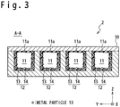
- FIG. 3 is a cross sectional view showing the structure of regeneration cooler 2 in the first embodiment along the A-A line of FIG. 1 .
- a coating 12 is formed on a wall surface 11a of the fuel passage 11 to at least partially cover the wall surface 11a.
- the coating 12 contains metal particles 13 and a coating material film 14.
- the metal particle 13 is adhered and fixed to the wall surface 11a of the fuel passage 11.
- the metal particle 13 is formed of the same material as the passage forming structure 10.
- the metal particle 13 may be also formed of the Ni-based alloy. It is desirable to form the metal particle 13 of same material as that of the passage forming structure 10, in order to improve the certainty of adhesion and fixation of the metal particles 13 to the wall surface 11a.
- the coating material film 14 is formed to at least partially cover the metal particles 13 and the wall surface 11a.
- the coating material film 14 is used to control the progress of thermal decomposition reaction in the fuel passage 11.
- the coating 12 contains the metal particles 13, the adhesion of the coating 12 onto the wall surface 11a of the fuel passage 11 is improved, so that it is possible to improve the certainty of forming the coating 12.
- the structure is shown in FIG. 1 in which the coating material film 14 completely covers the metal particles 13 and the wall surface 11a.
- the coating material film 14 may be configured to partially cover the metal particles 13 and the wall surface 11a. Even in such a structure, it is possible to control the progress of thermal decomposition reaction.
- the coating material film 14 a material to control the progress of thermal decomposition reaction of the liquid fuel is used.
- the coating material film 14 contains a material which restrains the progress of thermal decomposition reaction, or is formed of the material which restrains the progress of thermal decomposition reaction, compared with the material of the passage forming structure 10.
- a material is, for example, silica (SiO 2 ), alumina (Al 2 O 3 ), zirconia (ZrO 2 ) and oxide having oxygen storage capacity (OSC).
- the coating material film 14 contains at least one of silica (SiO 2 ), alumina (Al 2 O 3 ) and zirconia (ZrO 2 ), and it is more desirable that the coating material film 14 is formed of at least one selected from among silica (SiO 2 ), alumina (Al 2 O 3 ) and zirconia (ZrO 2 ).
- the coating material film 14 contains catalyst.
- the catalyst is, for example, a zeolite-based catalyst such as H-ZSM-5, PGM (Platinum Group Metal) catalyst such as platinum catalyst, palladium catalyst, and rhodium catalyst, and oxide catalyst with a large surface area.
- PGM Platinum Group Metal
- oxide catalyst with a large surface area.
- the coating material film 14 contains the catalyst having oxygen storage capacity (OSC)
- OSC oxygen storage capacity
- the catalyst having the oxygen storage capacity is, for example, a cerium oxide compound, praseodymium oxide compound, and lanthanoid oxysulfate.
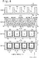
- FIG. 4 is cross sectional views showing the method of manufacturing the regeneration cooler 2 in the first embodiment.
- a metal plate 15 and a metal plate 16 having a plurality of ditches 16a formed are prepared (Step S1).
- the metal plates 15 and 16 are members used to configure the above-mentioned passage forming structure 10, and are formed of Ni-based alloy.
- the metal plate 16 has a proximal section 16b and wall sections 16c joined to the proximal section 16b.
- the ditch 16a is formed between the adjacent wall sections 16c.
- the plate 15 is welded to the wall sections 16c of the plate 16 in the condition that the metal particles 13 are put in the ditches 16a (Step S2).
- the welding of the metal plate 15 with the metal plate 16 is carried out by, for example, electron beam welding (EBW). Since the metal plate 15 is welded with the wall sections 16c of the metal plate 16, the ditches 16a are closed by the metal plate 15.
- the passage forming structure 10 is formed in which the fuel passages 11 have been formed thereinside.
- Step S3 the passage forming structure 10 is formed in which the metal particle 13 are adhered or fixed to the wall surfaces 11a of the fuel passages 11.
- the ditch 16a is fully filled with the metal particles 13.
- the metal particles 13 may be put in the ditch 16a to occupy only a part of the ditch 16a.
- the coating material film 14 is formed to at least partially cover the wall surface 11a of the fuel passage 11 and the metal particles 13.
- the structure is formed in which the wall surface 11a is covered with the coating 12 (Step S4).
- the forming of coating material film 14 may be carried out by passing slurry containing a raw material of the coating material film 14 through the fuel passage 11 to apply the slurry on the wall surface 11a, and then carrying out a sintering.
- the method of manufacturing the regeneration cooler 2 in this embodiment completes.
- the coating material film 14 contains a material restraining the progress of thermal decomposition reaction, compared with the material of the passage forming structure 10, or is formed of the material restraining the progress of thermal decomposition reaction.
- the coating material film 14 contains catalyst.
- the coating 12 contains the metal particles 13 adhered and fixed to the fuel passage 11, it is possible to improve the certainty of forming the coating 12 having a function to control the progress of thermal decomposition reaction.
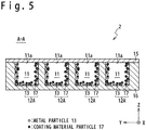
- FIG. 5 is a cross sectional view showing the structure of regeneration cooler 2 in the second embodiment.
- the structure of regeneration cooler 2 in the second embodiment along the A-A line of FIG. 1 is shown in FIG. 5 .
- a coating 12A is formed on the wall surface 11a of the fuel passage 11 to at least partially cover the wall surface 11a.
- the coating 12A contains the metal particles 13 and coating material particles 17. The metal particles 13 and the coating material particles 17 are mutually adhered and fixed to the wall 11a.
- the metal particle 13 is formed of the same material as that of the passage forming structure 10.
- the metal particle 13 may be also formed of the Ni-based alloy. It is desirable that the metal particle 13 is formed of the same material as that of the passage forming structure 10, in order to improve the certainty of adhesion and fixture of the metal particle 13 to the wall surface 11a.
- the coating material particle 17 is formed of a material of controlling the progress of thermal decomposition reaction of the liquid fuel.
- a material which restrains the progress of thermal decomposition reaction, or that the coating material particle 17 is formed of the material which restrains the progress of thermal decomposition reaction, compared with the material of the passage forming structure 10.
- Such a material is, for example, silica (SiO 2 ), alumina (Al 2 O 3 ), zirconia (ZrO 2 ) and oxide having oxygen storage capacity (OSC).
- the coating material film 14 contains at least one of silica (SiO 2 ), alumina (Al 2 O 3 ), and zirconia (ZrO 2 ), and it is more desirable that the coating material film 14 is formed of at least one material selected from among silica (SiO 2 ), alumina (Al 2 O 3 ) and zirconia (ZrO 2 ).
- the coating material particle 17 contains catalyst.
- the catalyst is, for example, zeolite catalyst such as H-ZSM-5, PGM (Platinum Group Metal) catalyst such as platinum catalyst, palladium catalyst and rhodium catalyst, and oxide catalyst having a large surface area.
- zeolite catalyst such as H-ZSM-5
- PGM (Platinum Group Metal) catalyst such as platinum catalyst, palladium catalyst and rhodium catalyst
- oxide catalyst having a large surface area Especially, when the coating material film 14 contains a catalyst having oxygen storage capacity (OSC), caulking can be restrained.
- the catalyst having oxygen storage capacity is, for example, cerium oxide compound, praseodymium oxide compound, lanthanoid oxysulfate.
- FIG. 6 is cross section views showing a manufacturing method of the regeneration cooler 2 in the second embodiment.
- the metal plate 15 and the metal plate 16 having the plurality of ditches 16a are prepared (Step S11).
- the metal plates 15 and 16 are the members used to form the above-mentioned passage forming structure 10, and for example, formed of Ni-based alloy.
- the metal plate 16 has the proximal section 16b and the wall sections 16c joined to the proximal section 16b.
- the ditch 16a is formed between the adjacent wall sections 16c.
- the metal plate 15 is welded with the wall sections 16c of the plate 16 in the condition that the metal particles 13, the coating material particles 17 and a binder are put in the ditch 16a (Step S12).
- the welding of the metal plate 15 with the metal plate 16 is carried out by, for example, electron beam welding (EBW).
- EBW electron beam welding
- the ditch 16a is closed by the metal plate 15 by welding the metal plate 15 with the wall sections 16c of the metal plate 16.
- the passage forming structure 10 is formed in which the fuel passages 11 are is formed inside the structure 10.
- the temperatures of metal plates 15 and 16 rise due to heat upon the welding, so that the at least a part of the metal particles 13 put inside the ditch 16a is adhered and fixed to the metal plates 15 and 16.
- the metal particles 13 and the metal plates 15 and 16 are formed of Ni-based alloys, the metal particles 13 adhere and fix to the metal plates 15 and 16 at about 1000 °C. This temperature is feasible due to heat by the welding.
- the binder is used to adhere and fix the coating material particles 17 to the wall surface 11a of the fuel passage 11.
- Metal hydroxide such as a powder of zirconium hydroxide and aluminum hydroxide is used.
- the binder of metal hydroxide decomposes to oxide due to heat by the welding.
- the coating material particles 17 can be surely adhered and fixed to the wall surface 11a of the fuel passage 11.
- a part of the coating material particles 17 is adhered and fixed directly to the wall surface 11a of the fuel passage 11 and the other part is adhered and fixed indirectly to the wall surface 11a through the metal particles 13 and the other coating material particles 17.
- the metal particles 13, the coating material particles 17 and the binder may be put in the ditch 16a to occupy only a part of the ditch 16a.
- Step S13 A part of the metal particles 13 and the coating material particles 17 which is not adhered and fixed to the metal plates 15 and 16 is removed.
- the coating 12A containing the metal particles 13 and the coating material particles 17 is formed to partially cover the wall surface 11a of the fuel passage 11 at least.
- the coating 12A contains the metal particles 13 adhered and fixed to the fuel passage 11 in addition to the coating material particles 17, it is possible to improve the certainty of forming the coating 12A having a function of controlling the progress of thermal decomposition reaction.
Landscapes
- Engineering & Computer Science (AREA)
- Chemical & Material Sciences (AREA)
- Combustion & Propulsion (AREA)
- Mechanical Engineering (AREA)
- General Engineering & Computer Science (AREA)
- Catalysts (AREA)
Abstract
Description
- The present invention relates to a regeneration cooler of a ramjet engine and a manufacturing method of the same.
- In a ramjet engine (e.g. a scramjet engine), a regeneration cooler is sometimes provided to cool a wall surface of a combustion chamber with liquid fuel and to heat the liquid fuel with heat from the combustion chamber to generate vaporized fuel. A fuel passage is formed in the regeneration cooler to supply the liquid fuel. A heat exchange is carried out between the liquid fuel flowing through the fuel passage and a combustion gas flowing through the combustion chamber, so that the wall surface of the combustion chamber is cooled and the vaporized fuel is generated from the liquid fuel. The regeneration cooler has an advantage in which the cooling of the wall surface of the combustion chamber and the generation of the vaporized fuel can be realized in a compact structure.
- In the regeneration cooler, thermal decomposition reaction occurs in which hydrocarbon of a large number of carbons contained in the liquid fuel is decomposed into hydrocarbon of a small number of carbons. When the thermal decomposition reaction is to be progressed intentionally, such a thermal decomposition reaction is sometimes called fuel reforming. When the fuel reforming is carried out, the regeneration cooler is sometimes configured to promote the thermal decomposition reaction by bringing the liquid fuel or vaporized fuel into contact with catalyst. The regeneration cooler having such a configuration is disclosed in, for example,
JP 2016-079862A - The inventor is considering controlling the thermal decomposition reaction in the regeneration cooler by forming a coating film on the fuel passage. A desirable degree of progress of the thermal decomposition reaction depends on application of the ramjet engine.
- For example, it is sometimes desirable to restrain the progress of thermal decomposition reaction, depending on the application of the ramjet engine. On the other hand, the regeneration cooler is often formed of a metal which can withstand a high temperature, e.g. a Ni-based alloy. Such a metal has a function of promoting the thermal decomposition reaction to a certain extent although being not as much as catalyst. Therefore, when the thermal decomposition reaction is to be restrained, it is desirable to form the coating film on the fuel passage to restrain the thermal decomposition reaction.
- On the other hand, it is sometimes desirable to promote the thermal decomposition reaction depending on the application of the ramjet engine. In such a case, it is desirable to form a coating film containing catalyst to promote the thermal decomposition reaction on the fuel passage.
JP 2014-145328A - One problem is in the difficulty of forming of a coating film on the fuel passage of the regeneration cooler. The regeneration cooler is often formed of a metal material which has the low adhesion of coating film. In such a case, the peeling of coating film can occur. The peeling of coating film is not desirable because it is possible to become a cause by which the fuel passage is choked.
- Therefore, the technical needs exist in the improvement the certainty of forming of coating film on the fuel passage of the regeneration cooler.
- Note that
JP 2011-152527A -
- [Patent Literature 1]
JP 2016-079862A - [Patent Literature 2]
JP 2014-145328A - [Patent Literature 3]
JP 2011-152527A - Therefore, an object of the present invention is to improve the certainty of forming of coating film on a fuel passage of a regeneration cooler of a ramjet engine. The other objects and new features of the present invention would be understood by a skilled person from the following disclosure.
- In an aspect of the present invention, a regeneration cooler used in a ramjet engine is provided.
- The regeneration cooler includes a passage forming structure inside which a fuel passage supplied with a liquid fuel is formed. A coating is formed to at least partially cover a wall surface of the fuel passage. The coating contains metal particles adhered and fixed to the wall surface of the fuel passage and coating material.
- In an example, the coating material contains a material to restrain thermal decomposition reaction of the liquid fuel, compared with a material of the passage forming structure. For example, it is desirable that the coating material contains at least one of silica, alumina and zirconia.
- In another example, the coating material may contain catalyst to promote the thermal decomposition reaction of the liquid fuel.
- In an example, it is desirable that the metal particles are formed of a material identical with that of the passage forming structure.
- In an example, the coating material is formed as a coating material film to at least partially coat the wall surface of the fuel passage and the metal particles adhered and fixed to the wall surface.
- In another example, the coating material may be formed as the coating material particles.
- In another aspect of the present invention, a method of manufacturing a regeneration cooler of a ramjet engine is provided. The manufacturing method includes preparing a first meal plate; preparing a second metal plate which has a proximal section and a plurality of wall sections connected with the proximal section and in which a ditch is formed between every adjacent two of the plurality of wall sections; welding the first metal plate with the plurality of wall sections of the second metal plate to close the ditches by the first metal plate in a condition that metal particles are put in the ditches; and forming a coating material film of a coating material to at least partially coat the wall surface of each of the fuel passages formed to close the ditches by the first metal plate in the welding and the metal particles adhered and fixed to the wall surface in the welding.
- In another aspect of the present invention, a method of manufacturing a regeneration cooler of a ramjet engine includes preparing a first meal plate; preparing a second metal plate which has a proximal section and a plurality of wall sections connected with the proximal section and in which a ditch is formed between every adjacent two of the plurality of wall sections; welding the first metal plate with the plurality of wall sections of the second metal plate to close the ditches by the first metal plate in a condition that metal particles, coating material particles formed of a coating material and a binder are put in the ditches; and removing a part of the metal particles and the coating material particles which is not adhered and fixed to the wall surfaces of the fuel passages formed by closing the ditches by the first metal plate.
- According to the present invention, it is possible to improve the certainty of forming the coating film on the fuel passages of the regeneration cooler of the ramjet engine.
-
-
FIG. 1 is a block diagram showing a configuration of ramjet engine containing a regeneration cooler. -
FIG. 2 is a perspective view schematically showing the regeneration cooler. -
FIG. 3 is a cross sectional view showing a structure of regeneration cooler in a first embodiment. -
FIG. 4 is a cross sectional view showing a method of manufacturing the regeneration cooler in the first embodiment. -
FIG. 5 is a cross sectional view showing a structure of regeneration cooler in a second embodiment. -
FIG. 6 is a cross sectional view showing the method of manufacturing the regeneration cooler in the second embodiment. - Hereinafter, embodiments of the present invention will be described with reference to the attached drawings. Note that a size ratio of components shown in the drawing differs from an actual size ratio to facilitate the understanding of the present invention.
-
FIG. 1 is a block diagram showing a configuration of ramjet engine containing a regeneration cooler according to a first embodiment of the present invention. InFIG. 1 , the whole ramjet engine is referred to by areference numeral 100. Note that an XYZ rectangular coordinate system is introduced to define directions in the following description. - The
ramjet engine 100 contains a tank 1, aregeneration cooler 2 and a combustion chamber forming member 3 (e.g. a cowl), and a fuel injector 4. Theregeneration cooler 2 contains awall surface 2a opposite to the combustionchamber forming member 3. Acombustion chamber 5 is formed between thewall surface 2a of theregeneration cooler 2 and the combustionchamber forming member 3. Compressed air is sent into thecombustion chamber 5 from upstream. - The tank 1 stores liquid fuel which contains hydrocarbon of a large number of carbons as a main component (for example, jet fuel such as JetA-1 fuel, kerosene and dodecene which contain carbons from 10 to 15, or liquid fuel which contains a combination of them). The liquid fuel is supplied to the
regeneration cooler 2 through a first pipe 6. The first pipe 6 connects a fuel discharge port of the tank 1 and afuel inflow port 2b of theregeneration cooler 2. - The
regeneration cooler 2 heats the supplied liquid fuel with the heat from thecombustion chamber 5 to generate vaporized fuel, and cools thewall surface 2a facing thecombustion chamber 5 with the liquid fuel. Theregeneration cooler 2 may be configured to thermally decompose the liquid fuel to carry out fuel reforming. Fuel gas as the vaporized fuel generated by theregeneration cooler 2 is supplied to the fuel injector 4 from thefuel outflow port 2c through asecond pipe 7. - The fuel injector 4 is provided for the combustion
chamber forming member 3 to inject the fuel gas into a flow of compressed air introduced into thecombustion chamber 5. Thus, a mixture gas is formed and combusted inside thecombustion chamber 5. The mixture gas is combusted in thecombustion chamber 5 to generate a combustion gas. The combustion gas flows to a downstream direction of thecombustion chamber 5 and is discharged from thecombustion chamber 5. InFIG. 1 , the flow of combustion gas is shown byarrow 8. In the configuration ofFIG. 1 , the direction into which combustion gas flows is a +X direction. -
FIG. 2 is a perspective view schematically showing theregeneration cooler 2. Theregeneration cooler 2 has apassage forming structure 10 havingfuel passages 11. Thefuel passage 11 is formed to communicate from thefuel inflow port 2b to thefuel outflow port 2c. In an example ofFIG. 2 , the fourfuel passages 11 are provided for thepassage forming structure 10. However, the number offuel passages 11 is optional. Thefuel passages 11 are arranged in line in a +Y direction and are formed to extend to the +X direction. -
FIG. 3 is a cross sectional view showing the structure ofregeneration cooler 2 in the first embodiment along the A-A line ofFIG. 1 . In theregeneration cooler 2 of the present embodiment, acoating 12 is formed on awall surface 11a of thefuel passage 11 to at least partially cover thewall surface 11a. Thecoating 12 containsmetal particles 13 and acoating material film 14. Themetal particle 13 is adhered and fixed to thewall surface 11a of thefuel passage 11. In an example, themetal particle 13 is formed of the same material as thepassage forming structure 10. For example, when thepassage forming structure 10 is formed of Ni-based alloy, themetal particle 13 may be also formed of the Ni-based alloy. It is desirable to form themetal particle 13 of same material as that of thepassage forming structure 10, in order to improve the certainty of adhesion and fixation of themetal particles 13 to thewall surface 11a. - Moreover, the
coating material film 14 is formed to at least partially cover themetal particles 13 and thewall surface 11a. Thecoating material film 14 is used to control the progress of thermal decomposition reaction in thefuel passage 11. - In such a structure, since the
coating 12 contains themetal particles 13, the adhesion of thecoating 12 onto thewall surface 11a of thefuel passage 11 is improved, so that it is possible to improve the certainty of forming thecoating 12. The structure is shown inFIG. 1 in which thecoating material film 14 completely covers themetal particles 13 and thewall surface 11a. However, thecoating material film 14 may be configured to partially cover themetal particles 13 and thewall surface 11a. Even in such a structure, it is possible to control the progress of thermal decomposition reaction. - As the
coating material film 14, a material to control the progress of thermal decomposition reaction of the liquid fuel is used. For example, when the progress of thermal decomposition reaction should be restrained, it is desirable that thecoating material film 14 contains a material which restrains the progress of thermal decomposition reaction, or is formed of the material which restrains the progress of thermal decomposition reaction, compared with the material of thepassage forming structure 10. Such a material is, for example, silica (SiO2), alumina (Al2O3), zirconia (ZrO2) and oxide having oxygen storage capacity (OSC). In order to restrain the progress of thermal decomposition reaction, it is desirable that thecoating material film 14 contains at least one of silica (SiO2), alumina (Al2O3) and zirconia (ZrO2), and it is more desirable that thecoating material film 14 is formed of at least one selected from among silica (SiO2), alumina (Al2O3) and zirconia (ZrO2). - On the other hand, when the progress of thermal decomposition reaction should be promoted (that is, when the fuel reforming should be carried out aggressively), it is desirable that the
coating material film 14 contains catalyst. The catalyst is, for example, a zeolite-based catalyst such as H-ZSM-5, PGM (Platinum Group Metal) catalyst such as platinum catalyst, palladium catalyst, and rhodium catalyst, and oxide catalyst with a large surface area. Especially, when thecoating material film 14 contains the catalyst having oxygen storage capacity (OSC), caulking can be restrained. The catalyst having the oxygen storage capacity is, for example, a cerium oxide compound, praseodymium oxide compound, and lanthanoid oxysulfate. - Next, a method of manufacturing the
regeneration cooler 2 in the present embodiment will be described.FIG. 4 is cross sectional views showing the method of manufacturing theregeneration cooler 2 in the first embodiment. - First, a
metal plate 15 and ametal plate 16 having a plurality ofditches 16a formed are prepared (Step S1). Themetal plates passage forming structure 10, and are formed of Ni-based alloy. Themetal plate 16 has aproximal section 16b andwall sections 16c joined to theproximal section 16b. Theditch 16a is formed between theadjacent wall sections 16c. - Subsequently, the
plate 15 is welded to thewall sections 16c of theplate 16 in the condition that themetal particles 13 are put in theditches 16a (Step S2). The welding of themetal plate 15 with themetal plate 16 is carried out by, for example, electron beam welding (EBW). Since themetal plate 15 is welded with thewall sections 16c of themetal plate 16, theditches 16a are closed by themetal plate 15. Thus, thepassage forming structure 10 is formed in which thefuel passages 11 have been formed thereinside. - When the
metal plate 15 is welded with themetal plate 16, the temperatures ofmetal plates metal particles 13 put inside theditch 16a is adhered and fixed to themetal plates metal particles 13 and themetal plates metal particles 13 adhered and fixed to themetal plates metal particles 13 which is not adhered or fixed to themetal plates passage forming structure 10 is formed in which themetal particle 13 are adhered or fixed to the wall surfaces 11a of thefuel passages 11. - In the welding at step S2, it is not necessary that the
ditch 16a is fully filled with themetal particles 13. Themetal particles 13 may be put in theditch 16a to occupy only a part of theditch 16a. - Moreover, the
coating material film 14 is formed to at least partially cover thewall surface 11a of thefuel passage 11 and themetal particles 13. Thus, the structure is formed in which thewall surface 11a is covered with the coating 12 (Step S4). The forming ofcoating material film 14 may be carried out by passing slurry containing a raw material of thecoating material film 14 through thefuel passage 11 to apply the slurry on thewall surface 11a, and then carrying out a sintering. Thus, the method of manufacturing theregeneration cooler 2 in this embodiment completes. - As mentioned above, various materials can be used as the
coating material film 14. For example, when the progress of thermal decomposition reaction should be restrained, it is desirable that thecoating material film 14 contains a material restraining the progress of thermal decomposition reaction, compared with the material of thepassage forming structure 10, or is formed of the material restraining the progress of thermal decomposition reaction. On the other hand, when the progress of thermal decomposition reaction should be promoted (that is, when the fuel reforming should be carried out aggressively), it is desirable that thecoating material film 14 contains catalyst. - According to the structure and manufacturing method of the
regeneration cooler 2 in the first embodiment, because thecoating 12 contains themetal particles 13 adhered and fixed to thefuel passage 11, it is possible to improve the certainty of forming thecoating 12 having a function to control the progress of thermal decomposition reaction. -
FIG. 5 is a cross sectional view showing the structure ofregeneration cooler 2 in the second embodiment. The structure ofregeneration cooler 2 in the second embodiment along the A-A line ofFIG. 1 is shown inFIG. 5 . - In the second embodiment, a
coating 12A is formed on thewall surface 11a of thefuel passage 11 to at least partially cover thewall surface 11a. In the present embodiment, thecoating 12A contains themetal particles 13 andcoating material particles 17. Themetal particles 13 and thecoating material particles 17 are mutually adhered and fixed to thewall 11a. - In an example, the
metal particle 13 is formed of the same material as that of thepassage forming structure 10. For example, when thepassage forming structure 10 is formed of Ni-based alloy, themetal particle 13 may be also formed of the Ni-based alloy. It is desirable that themetal particle 13 is formed of the same material as that of thepassage forming structure 10, in order to improve the certainty of adhesion and fixture of themetal particle 13 to thewall surface 11a. - The
coating material particle 17 is formed of a material of controlling the progress of thermal decomposition reaction of the liquid fuel. For example, when the progress of thermal decomposition reaction should be restrained, it is desirable that thecoating material particle 17 contains a material which restrains the progress of thermal decomposition reaction, or that thecoating material particle 17 is formed of the material which restrains the progress of thermal decomposition reaction, compared with the material of thepassage forming structure 10. Such a material is, for example, silica (SiO2), alumina (Al2O3), zirconia (ZrO2) and oxide having oxygen storage capacity (OSC). To restrain the progress of thermal decomposition reaction, it is desirable that thecoating material film 14 contains at least one of silica (SiO2), alumina (Al2O3), and zirconia (ZrO2), and it is more desirable that thecoating material film 14 is formed of at least one material selected from among silica (SiO2), alumina (Al2O3) and zirconia (ZrO2). - On the other hand, when the progress of thermal decomposition reaction should be promoted (that is, when the fuel reforming should be carried out aggressively), it is desirable that the
coating material particle 17 contains catalyst. The catalyst is, for example, zeolite catalyst such as H-ZSM-5, PGM (Platinum Group Metal) catalyst such as platinum catalyst, palladium catalyst and rhodium catalyst, and oxide catalyst having a large surface area. Especially, when thecoating material film 14 contains a catalyst having oxygen storage capacity (OSC), caulking can be restrained. The catalyst having oxygen storage capacity is, for example, cerium oxide compound, praseodymium oxide compound, lanthanoid oxysulfate. - Next, a method of manufacturing the
regeneration cooler 2 in the second embodiment will be described.FIG. 6 is cross section views showing a manufacturing method of theregeneration cooler 2 in the second embodiment. - Like the first embodiment, the
metal plate 15 and themetal plate 16 having the plurality ofditches 16a are prepared (Step S11). Themetal plates passage forming structure 10, and for example, formed of Ni-based alloy. Themetal plate 16 has theproximal section 16b and thewall sections 16c joined to theproximal section 16b. Theditch 16a is formed between theadjacent wall sections 16c. - Next, the
metal plate 15 is welded with thewall sections 16c of theplate 16 in the condition that themetal particles 13, thecoating material particles 17 and a binder are put in theditch 16a (Step S12). The welding of themetal plate 15 with themetal plate 16 is carried out by, for example, electron beam welding (EBW). Theditch 16a is closed by themetal plate 15 by welding themetal plate 15 with thewall sections 16c of themetal plate 16. Thus, thepassage forming structure 10 is formed in which thefuel passages 11 are is formed inside thestructure 10. - When the
metal plate 15 is welded with themetal plate 16, the temperatures ofmetal plates metal particles 13 put inside theditch 16a is adhered and fixed to themetal plates metal particles 13 and themetal plates metal particles 13 adhere and fix to themetal plates - The binder is used to adhere and fix the
coating material particles 17 to thewall surface 11a of thefuel passage 11. As the binder,
Metal hydroxide such as a powder of zirconium hydroxide and aluminum hydroxide is used. The binder of metal hydroxide decomposes to oxide due to heat by the welding. Thus, thecoating material particles 17 can be surely adhered and fixed to thewall surface 11a of thefuel passage 11. A part of thecoating material particles 17 is adhered and fixed directly to thewall surface 11a of thefuel passage 11 and the other part is adhered and fixed indirectly to thewall surface 11a through themetal particles 13 and the othercoating material particles 17. - Also, in the welding at the step S12, it is not necessary to fully fill the
ditch 16a with themetal particles 13, thecoating material particles 17 and the binder. Themetal particles 13, thecoating material particles 17 and the binder may be put in theditch 16a to occupy only a part of theditch 16a. - A part of the
metal particles 13 and thecoating material particles 17 which is not adhered and fixed to themetal plates coating 12A containing themetal particles 13 and thecoating material particles 17 is formed to partially cover thewall surface 11a of thefuel passage 11 at least. - According to the structure and manufacturing method of the
regeneration cooler 2 in the present embodiment, because thecoating 12A contains themetal particles 13 adhered and fixed to thefuel passage 11 in addition to thecoating material particles 17, it is possible to improve the certainty of forming thecoating 12A having a function of controlling the progress of thermal decomposition reaction. - In the above, the embodiments of the present invention have been specifically described. However, the present invention is not limited to the above-mentioned embodiments. It would be understood by a skilled person that the present invention can be implemented together with various changes or modifications. Also, it is possible for the technique in one embodiment to be applied to another embodiment.
- The present application is based on Japanese Patent Application No.
JP 2017-077377, filed on April 10, 2017
Claims (14)
- A regeneration cooler used for a ramjet engine, comprising a passage forming structure in which a fuel passage through which a liquid fuel is supplied is formed,
wherein a coating is formed in the fuel passage to at least partially cover a wall surface of the fuel passage,
wherein the coating comprises:metal particles adhered and fixed to the wall surface of the fuel passage; anda coating material. - The regeneration cooler according to claim 1, wherein the coating material contains a material which restrains thermal decomposition reaction of the liquid fuel, compared with a material of the passage forming structure.
- The regeneration cooler according to claim 1, wherein the coating material contains at least one of silica, alumina and zirconia.
- The regeneration cooler according to claim 1, wherein the coating material contains catalyst which promotes thermal decomposition reaction of the liquid fuel.
- The regeneration cooler according to any one of claims 1 to 4, wherein the metal particles are formed of a material identical with that of the passage forming structure.
- The regeneration cooler according to any one of claims 1 to 5,
wherein the coating material is configured as a coating material film to at least partially cover the wall surface of the fuel passage and the metal particles adhered and fixed to the wall surface. - The regeneration cooler according to any one of claims 1 to 5,
wherein the coating material is configured as coating material particles. - A ramjet engine comprising the regeneration cooler according to any one of claims 1 to 7.
- A method of manufacturing a regeneration cooler of a ramjet engine, comprising:preparing a first metal plate;preparing a second metal plate which has a proximal section and a plurality of wall sections connected with the proximal section, and in which a ditch is formed between every adjacent two of the plurality of wall sections;welding the first metal plate with the wall sections of the second metal plate to close the ditches by the first metal plate, in a condition that metal particles are put in each of the ditches; andforming a coating material film of a coating material to at least partially cover wall surfaces of fuel passages formed by closing the ditches by the first metal plate in the welding and the metal particles adhered and fixed to the wall surfaces in the welding.
- A method of manufacturing a regeneration cooler of a ramjet engine, comprising:preparing a first metal plate;preparing a second metal plate which has a proximal section and a plurality of wall sections connected with the proximal section, and in which a ditch is formed between every adjacent two of the plurality of wall sections;welding the first metal plate with the wall sections of the second metal plate to close the ditches by the first metal plate, in a condition that metal particles, coating material particles formed of a coating material, and a binder are put in each of the ditches; andremoving a part of the metal particles and the coating material particles which is not adhered and fixed to wall surfaces of fuel passages formed by closing the ditches by the first metal plate.
- The method of manufacturing a regeneration cooler according to claim 9 or 10, wherein the coating material contains a material which restrains thermal decomposition reaction of liquid fuel, compared with materials of the first metal plate and the second metal plate.
- The method of manufacturing a regeneration cooler according to claim 9 or 10, wherein the coating material contains a material of at least one of silica, alumina and zirconia.
- The method of manufacturing a regeneration cooler according to claim 9 or 10, wherein the coating material contains catalyst which promotes thermal decomposition reaction of liquid fuel.
- The method of manufacturing a regeneration cooler according to any one of claims 9 to 13, wherein the metal particles are formed of the same material as that of the first metal plate and the second metal plate.
Applications Claiming Priority (2)
| Application Number | Priority Date | Filing Date | Title |
|---|---|---|---|
| JP2017077377A JP6806618B2 (en) | 2017-04-10 | 2017-04-10 | Ramjet engine regenerative cooler and its manufacturing method |
| PCT/JP2017/041348 WO2018189944A1 (en) | 2017-04-10 | 2017-11-16 | Regenerative cooler for ramjet engine, and method for manufacturing same |
Publications (3)
| Publication Number | Publication Date |
|---|---|
| EP3591210A1 true EP3591210A1 (en) | 2020-01-08 |
| EP3591210A4 EP3591210A4 (en) | 2020-03-04 |
| EP3591210B1 EP3591210B1 (en) | 2021-04-07 |
Family
ID=63792466
Family Applications (1)
| Application Number | Title | Priority Date | Filing Date |
|---|---|---|---|
| EP17905551.2A Active EP3591210B1 (en) | 2017-04-10 | 2017-11-16 | Regenerative cooler for ramjet engine, and method for manufacturing same |
Country Status (5)
| Country | Link |
|---|---|
| US (1) | US11512852B2 (en) |
| EP (1) | EP3591210B1 (en) |
| JP (1) | JP6806618B2 (en) |
| AU (1) | AU2017409263B2 (en) |
| WO (1) | WO2018189944A1 (en) |
Cited By (2)
| Publication number | Priority date | Publication date | Assignee | Title |
|---|---|---|---|---|
| CN111636966A (en) * | 2020-05-28 | 2020-09-08 | 清华大学 | Engine and its cooling system |
| DE102022000497A1 (en) | 2021-02-11 | 2022-08-11 | Mathias Herrmann | Reaction and design concept for engines for catalytic control / energetic triggering (e.g. with metal additives) of the internal speed (acceleration) and exit speed with influencing of temperature and pressure for improved efficiency and combustion chamber adaptation (driver concept) |
Families Citing this family (2)
| Publication number | Priority date | Publication date | Assignee | Title |
|---|---|---|---|---|
| DE102021110614A1 (en) * | 2021-04-26 | 2022-10-27 | Rolls-Royce Deutschland Ltd & Co Kg | Combustion chamber assembly for an engine with at least one heat exchange channel for fuel to be injected |
| CN113389659B (en) * | 2021-07-27 | 2022-10-25 | 中国人民解放军国防科技大学 | Design method of high-temperature fuel gas channel with low heat sink |
Family Cites Families (20)
| Publication number | Priority date | Publication date | Assignee | Title |
|---|---|---|---|---|
| US2655786A (en) | 1950-09-18 | 1953-10-20 | Phillips Petroleum Co | Method of operating jet engines with fuel reforming |
| US3925983A (en) * | 1974-04-17 | 1975-12-16 | Us Air Force | Transpiration cooling washer assembly |
| JP3091892B2 (en) | 1992-06-08 | 2000-09-25 | 科学技術庁航空宇宙技術研究所長 | Space plane and its manufacturing method |
| CA2105188A1 (en) * | 1992-09-22 | 1994-03-23 | George A. Coffinberry | Coated article for hot hydrocarbon fluid and method of preventing fuel thermal degradation deposits |
| JP3196549B2 (en) | 1995-01-09 | 2001-08-06 | 株式会社日立製作所 | Power generation system with fuel reformer |
| DE19804232C2 (en) | 1998-02-04 | 2000-06-29 | Daimler Chrysler Ag | Combustion chamber for high-performance engines and nozzles |
| US6358040B1 (en) | 2000-03-17 | 2002-03-19 | Precision Combustion, Inc. | Method and apparatus for a fuel-rich catalytic reactor |
| US6472014B1 (en) * | 2001-04-17 | 2002-10-29 | Novellus Systems, Inc. | Uniform surface texturing for PVD/CVD hardware |
| JP4033101B2 (en) | 2003-09-30 | 2008-01-16 | 株式会社日立製作所 | Hydride turbine |
| US7874060B2 (en) * | 2004-06-24 | 2011-01-25 | Northwestern University | Method of making optics element |
| US20100175379A1 (en) | 2009-01-09 | 2010-07-15 | General Electric Company | Pre-mix catalytic partial oxidation fuel reformer for staged and reheat gas turbine systems |
| US8453456B2 (en) * | 2009-03-25 | 2013-06-04 | United Technologies Corporation | Fuel-cooled flexible heat exchanger with thermoelectric device compression |
| WO2010116603A1 (en) * | 2009-03-30 | 2010-10-14 | 財団法人石油産業活性化センター | Production method for alkyl benzenes, and catalyst used in same |
| JP5596360B2 (en) | 2010-01-28 | 2014-09-24 | 日立エーアイシー株式会社 | Hydrogen catalyst member and manufacturing method thereof |
| JP5832340B2 (en) * | 2012-03-08 | 2015-12-16 | 三菱重工業株式会社 | Fuel supply system, scramjet engine and method of operating the same |
| US9440851B2 (en) | 2012-05-23 | 2016-09-13 | Herng Shinn Hwang | Flex-fuel hydrogen generator for IC engines and gas turbines |
| JP6021661B2 (en) | 2013-01-30 | 2016-11-09 | 三菱重工業株式会社 | Fuel supply system, scramjet engine and method of operating the same |
| JP6404078B2 (en) | 2014-10-15 | 2018-10-10 | 三菱重工業株式会社 | FUEL SUPPLY SYSTEM, JET ENGINE, AND METHOD FOR MANUFACTURING FUEL SUPPLY SYSTEM |
| JP6355106B2 (en) * | 2015-03-24 | 2018-07-11 | 三菱重工業株式会社 | Fuel reforming mechanism, fluid reforming mechanism, jet engine equipped with fuel reforming mechanism, and method for manufacturing fuel reforming mechanism |
| JP6680508B2 (en) | 2015-10-20 | 2020-04-15 | 周 中村 | Low back pain chair |
-
2017
- 2017-04-10 JP JP2017077377A patent/JP6806618B2/en active Active
- 2017-11-16 WO PCT/JP2017/041348 patent/WO2018189944A1/en not_active Ceased
- 2017-11-16 AU AU2017409263A patent/AU2017409263B2/en active Active
- 2017-11-16 US US16/498,033 patent/US11512852B2/en active Active
- 2017-11-16 EP EP17905551.2A patent/EP3591210B1/en active Active
Cited By (3)
| Publication number | Priority date | Publication date | Assignee | Title |
|---|---|---|---|---|
| CN111636966A (en) * | 2020-05-28 | 2020-09-08 | 清华大学 | Engine and its cooling system |
| CN111636966B (en) * | 2020-05-28 | 2021-06-25 | 清华大学 | Engine and its cooling system |
| DE102022000497A1 (en) | 2021-02-11 | 2022-08-11 | Mathias Herrmann | Reaction and design concept for engines for catalytic control / energetic triggering (e.g. with metal additives) of the internal speed (acceleration) and exit speed with influencing of temperature and pressure for improved efficiency and combustion chamber adaptation (driver concept) |
Also Published As
| Publication number | Publication date |
|---|---|
| EP3591210A4 (en) | 2020-03-04 |
| WO2018189944A1 (en) | 2018-10-18 |
| JP2018178809A (en) | 2018-11-15 |
| AU2017409263B2 (en) | 2020-11-26 |
| US20200386186A1 (en) | 2020-12-10 |
| EP3591210B1 (en) | 2021-04-07 |
| AU2017409263A1 (en) | 2019-10-24 |
| US11512852B2 (en) | 2022-11-29 |
| JP6806618B2 (en) | 2021-01-06 |
Similar Documents
| Publication | Publication Date | Title |
|---|---|---|
| EP3591210B1 (en) | Regenerative cooler for ramjet engine, and method for manufacturing same | |
| EP1710523B1 (en) | Continuous firing kiln and process for producing porous ceramic member therewith | |
| RU2330162C2 (en) | High temperature foliated system for heat removal and method for its production (versions) | |
| US6616969B2 (en) | Apparatus and method for selectively coating internal and external surfaces of an airfoil | |
| RU2443459C2 (en) | Substrate for black filter with "washcoat" coating | |
| EP3162917B1 (en) | Methods of repairing a thermal barrier coating of a gas turbine component and the resulting components | |
| CN109874330B (en) | Method for coating the surface of a solid substrate with a layer containing a ceramic compound and the resulting coated substrate | |
| US20060073970A1 (en) | Honeycomb structure body | |
| JP7214720B2 (en) | Coated turbomachinery components and related manufacturing methods | |
| US11219100B2 (en) | Fluid heating component, fluid heating component complex, and manufacturing method of fluid heating component | |
| US10265657B2 (en) | Temperature maintenance and regulation of vehicle exhaust catalyst systems with phase change materials | |
| US9718026B2 (en) | Exhaust gas purification filter | |
| CN106906471A (en) | Gas turbine components with improved Thermal barrier coating systems | |
| US20110091361A1 (en) | Filter for removing particles from a gas stream and method for the manufacture thereof | |
| CN108251832B (en) | Method of depositing one or more layers of microspheres to form a thermal barrier coating | |
| JP2928063B2 (en) | Coated articles and methods for preventing fuel thermal degradation deposits | |
| US10465548B2 (en) | Shroud and method for implementing abradable coating | |
| JP4532278B2 (en) | Catalyst support having passivation layer and method for producing the same | |
| US20140170031A1 (en) | Exhaust Aftertreatment System | |
| EP3090137B1 (en) | Fusible bond for gas turbine engine coating system | |
| US11174774B2 (en) | Structures for catalytic converters | |
| CN109642496A (en) | Thermal barriers and its manufacturing method for engine | |
| Hartropp et al. | The contribution of thermal barrier coatings to improvements in the life and performance of gas turbine components | |
| Goral et al. | 21 Advanced Technologies in the Aerospace Industry | |
| US20060242951A1 (en) | Refractory material retention device |
Legal Events
| Date | Code | Title | Description |
|---|---|---|---|
| STAA | Information on the status of an ep patent application or granted ep patent |
Free format text: STATUS: THE INTERNATIONAL PUBLICATION HAS BEEN MADE |
|
| PUAI | Public reference made under article 153(3) epc to a published international application that has entered the european phase |
Free format text: ORIGINAL CODE: 0009012 |
|
| STAA | Information on the status of an ep patent application or granted ep patent |
Free format text: STATUS: REQUEST FOR EXAMINATION WAS MADE |
|
| 17P | Request for examination filed |
Effective date: 20191001 |
|
| AK | Designated contracting states |
Kind code of ref document: A1 Designated state(s): AL AT BE BG CH CY CZ DE DK EE ES FI FR GB GR HR HU IE IS IT LI LT LU LV MC MK MT NL NO PL PT RO RS SE SI SK SM TR |
|
| A4 | Supplementary search report drawn up and despatched |
Effective date: 20200205 |
|
| RIC1 | Information provided on ipc code assigned before grant |
Ipc: F02K 7/14 20060101AFI20200130BHEP Ipc: F23R 3/30 20060101ALI20200130BHEP Ipc: F02K 7/10 20060101ALI20200130BHEP Ipc: F02C 7/22 20060101ALI20200130BHEP Ipc: F02C 7/224 20060101ALI20200130BHEP |
|
| DAV | Request for validation of the european patent (deleted) | ||
| GRAP | Despatch of communication of intention to grant a patent |
Free format text: ORIGINAL CODE: EPIDOSNIGR1 |
|
| STAA | Information on the status of an ep patent application or granted ep patent |
Free format text: STATUS: GRANT OF PATENT IS INTENDED |
|
| INTG | Intention to grant announced |
Effective date: 20201028 |
|
| GRAS | Grant fee paid |
Free format text: ORIGINAL CODE: EPIDOSNIGR3 |
|
| GRAA | (expected) grant |
Free format text: ORIGINAL CODE: 0009210 |
|
| STAA | Information on the status of an ep patent application or granted ep patent |
Free format text: STATUS: THE PATENT HAS BEEN GRANTED |
|
| AK | Designated contracting states |
Kind code of ref document: B1 Designated state(s): AL AT BE BG CH CY CZ DE DK EE ES FI FR GB GR HR HU IE IS IT LI LT LU LV MC MK MT NL NO PL PT RO RS SE SI SK SM TR |
|
| REG | Reference to a national code |
Ref country code: GB Ref legal event code: FG4D |
|
| REG | Reference to a national code |
Ref country code: AT Ref legal event code: REF Ref document number: 1379985 Country of ref document: AT Kind code of ref document: T Effective date: 20210415 Ref country code: CH Ref legal event code: EP |
|
| REG | Reference to a national code |
Ref country code: DE Ref legal event code: R096 Ref document number: 602017036498 Country of ref document: DE |
|
| REG | Reference to a national code |
Ref country code: IE Ref legal event code: FG4D |
|
| REG | Reference to a national code |
Ref country code: LT Ref legal event code: MG9D |
|
| REG | Reference to a national code |
Ref country code: NL Ref legal event code: MP Effective date: 20210407 Ref country code: AT Ref legal event code: MK05 Ref document number: 1379985 Country of ref document: AT Kind code of ref document: T Effective date: 20210407 |
|
| PG25 | Lapsed in a contracting state [announced via postgrant information from national office to epo] |
Ref country code: FI Free format text: LAPSE BECAUSE OF FAILURE TO SUBMIT A TRANSLATION OF THE DESCRIPTION OR TO PAY THE FEE WITHIN THE PRESCRIBED TIME-LIMIT Effective date: 20210407 Ref country code: LT Free format text: LAPSE BECAUSE OF FAILURE TO SUBMIT A TRANSLATION OF THE DESCRIPTION OR TO PAY THE FEE WITHIN THE PRESCRIBED TIME-LIMIT Effective date: 20210407 Ref country code: HR Free format text: LAPSE BECAUSE OF FAILURE TO SUBMIT A TRANSLATION OF THE DESCRIPTION OR TO PAY THE FEE WITHIN THE PRESCRIBED TIME-LIMIT Effective date: 20210407 Ref country code: BG Free format text: LAPSE BECAUSE OF FAILURE TO SUBMIT A TRANSLATION OF THE DESCRIPTION OR TO PAY THE FEE WITHIN THE PRESCRIBED TIME-LIMIT Effective date: 20210707 Ref country code: AT Free format text: LAPSE BECAUSE OF FAILURE TO SUBMIT A TRANSLATION OF THE DESCRIPTION OR TO PAY THE FEE WITHIN THE PRESCRIBED TIME-LIMIT Effective date: 20210407 Ref country code: NL Free format text: LAPSE BECAUSE OF FAILURE TO SUBMIT A TRANSLATION OF THE DESCRIPTION OR TO PAY THE FEE WITHIN THE PRESCRIBED TIME-LIMIT Effective date: 20210407 |
|
| PG25 | Lapsed in a contracting state [announced via postgrant information from national office to epo] |
Ref country code: PL Free format text: LAPSE BECAUSE OF FAILURE TO SUBMIT A TRANSLATION OF THE DESCRIPTION OR TO PAY THE FEE WITHIN THE PRESCRIBED TIME-LIMIT Effective date: 20210407 Ref country code: LV Free format text: LAPSE BECAUSE OF FAILURE TO SUBMIT A TRANSLATION OF THE DESCRIPTION OR TO PAY THE FEE WITHIN THE PRESCRIBED TIME-LIMIT Effective date: 20210407 Ref country code: PT Free format text: LAPSE BECAUSE OF FAILURE TO SUBMIT A TRANSLATION OF THE DESCRIPTION OR TO PAY THE FEE WITHIN THE PRESCRIBED TIME-LIMIT Effective date: 20210809 Ref country code: NO Free format text: LAPSE BECAUSE OF FAILURE TO SUBMIT A TRANSLATION OF THE DESCRIPTION OR TO PAY THE FEE WITHIN THE PRESCRIBED TIME-LIMIT Effective date: 20210707 Ref country code: RS Free format text: LAPSE BECAUSE OF FAILURE TO SUBMIT A TRANSLATION OF THE DESCRIPTION OR TO PAY THE FEE WITHIN THE PRESCRIBED TIME-LIMIT Effective date: 20210407 Ref country code: SE Free format text: LAPSE BECAUSE OF FAILURE TO SUBMIT A TRANSLATION OF THE DESCRIPTION OR TO PAY THE FEE WITHIN THE PRESCRIBED TIME-LIMIT Effective date: 20210407 Ref country code: IS Free format text: LAPSE BECAUSE OF FAILURE TO SUBMIT A TRANSLATION OF THE DESCRIPTION OR TO PAY THE FEE WITHIN THE PRESCRIBED TIME-LIMIT Effective date: 20210807 Ref country code: GR Free format text: LAPSE BECAUSE OF FAILURE TO SUBMIT A TRANSLATION OF THE DESCRIPTION OR TO PAY THE FEE WITHIN THE PRESCRIBED TIME-LIMIT Effective date: 20210708 |
|
| REG | Reference to a national code |
Ref country code: DE Ref legal event code: R097 Ref document number: 602017036498 Country of ref document: DE |
|
| PG25 | Lapsed in a contracting state [announced via postgrant information from national office to epo] |
Ref country code: EE Free format text: LAPSE BECAUSE OF FAILURE TO SUBMIT A TRANSLATION OF THE DESCRIPTION OR TO PAY THE FEE WITHIN THE PRESCRIBED TIME-LIMIT Effective date: 20210407 Ref country code: ES Free format text: LAPSE BECAUSE OF FAILURE TO SUBMIT A TRANSLATION OF THE DESCRIPTION OR TO PAY THE FEE WITHIN THE PRESCRIBED TIME-LIMIT Effective date: 20210407 Ref country code: SM Free format text: LAPSE BECAUSE OF FAILURE TO SUBMIT A TRANSLATION OF THE DESCRIPTION OR TO PAY THE FEE WITHIN THE PRESCRIBED TIME-LIMIT Effective date: 20210407 Ref country code: SK Free format text: LAPSE BECAUSE OF FAILURE TO SUBMIT A TRANSLATION OF THE DESCRIPTION OR TO PAY THE FEE WITHIN THE PRESCRIBED TIME-LIMIT Effective date: 20210407 Ref country code: CZ Free format text: LAPSE BECAUSE OF FAILURE TO SUBMIT A TRANSLATION OF THE DESCRIPTION OR TO PAY THE FEE WITHIN THE PRESCRIBED TIME-LIMIT Effective date: 20210407 Ref country code: DK Free format text: LAPSE BECAUSE OF FAILURE TO SUBMIT A TRANSLATION OF THE DESCRIPTION OR TO PAY THE FEE WITHIN THE PRESCRIBED TIME-LIMIT Effective date: 20210407 Ref country code: RO Free format text: LAPSE BECAUSE OF FAILURE TO SUBMIT A TRANSLATION OF THE DESCRIPTION OR TO PAY THE FEE WITHIN THE PRESCRIBED TIME-LIMIT Effective date: 20210407 |
|
| PLBE | No opposition filed within time limit |
Free format text: ORIGINAL CODE: 0009261 |
|
| STAA | Information on the status of an ep patent application or granted ep patent |
Free format text: STATUS: NO OPPOSITION FILED WITHIN TIME LIMIT |
|
| 26N | No opposition filed |
Effective date: 20220110 |
|
| PG25 | Lapsed in a contracting state [announced via postgrant information from national office to epo] |
Ref country code: IS Free format text: LAPSE BECAUSE OF FAILURE TO SUBMIT A TRANSLATION OF THE DESCRIPTION OR TO PAY THE FEE WITHIN THE PRESCRIBED TIME-LIMIT Effective date: 20210807 Ref country code: AL Free format text: LAPSE BECAUSE OF FAILURE TO SUBMIT A TRANSLATION OF THE DESCRIPTION OR TO PAY THE FEE WITHIN THE PRESCRIBED TIME-LIMIT Effective date: 20210407 |
|
| REG | Reference to a national code |
Ref country code: DE Ref legal event code: R119 Ref document number: 602017036498 Country of ref document: DE |
|
| PG25 | Lapsed in a contracting state [announced via postgrant information from national office to epo] |
Ref country code: MC Free format text: LAPSE BECAUSE OF FAILURE TO SUBMIT A TRANSLATION OF THE DESCRIPTION OR TO PAY THE FEE WITHIN THE PRESCRIBED TIME-LIMIT Effective date: 20210407 |
|
| REG | Reference to a national code |
Ref country code: CH Ref legal event code: PL |
|
| GBPC | Gb: european patent ceased through non-payment of renewal fee |
Effective date: 20211116 |
|
| PG25 | Lapsed in a contracting state [announced via postgrant information from national office to epo] |
Ref country code: LU Free format text: LAPSE BECAUSE OF NON-PAYMENT OF DUE FEES Effective date: 20211116 Ref country code: IT Free format text: LAPSE BECAUSE OF FAILURE TO SUBMIT A TRANSLATION OF THE DESCRIPTION OR TO PAY THE FEE WITHIN THE PRESCRIBED TIME-LIMIT Effective date: 20210407 Ref country code: BE Free format text: LAPSE BECAUSE OF NON-PAYMENT OF DUE FEES Effective date: 20211130 |
|
| REG | Reference to a national code |
Ref country code: BE Ref legal event code: MM Effective date: 20211130 |
|
| PG25 | Lapsed in a contracting state [announced via postgrant information from national office to epo] |
Ref country code: IE Free format text: LAPSE BECAUSE OF NON-PAYMENT OF DUE FEES Effective date: 20211116 Ref country code: GB Free format text: LAPSE BECAUSE OF NON-PAYMENT OF DUE FEES Effective date: 20211116 Ref country code: DE Free format text: LAPSE BECAUSE OF NON-PAYMENT OF DUE FEES Effective date: 20220601 |
|
| PG25 | Lapsed in a contracting state [announced via postgrant information from national office to epo] |
Ref country code: CY Free format text: LAPSE BECAUSE OF FAILURE TO SUBMIT A TRANSLATION OF THE DESCRIPTION OR TO PAY THE FEE WITHIN THE PRESCRIBED TIME-LIMIT Effective date: 20210407 |
|
| PG25 | Lapsed in a contracting state [announced via postgrant information from national office to epo] |
Ref country code: LI Free format text: LAPSE BECAUSE OF NON-PAYMENT OF DUE FEES Effective date: 20220630 Ref country code: HU Free format text: LAPSE BECAUSE OF FAILURE TO SUBMIT A TRANSLATION OF THE DESCRIPTION OR TO PAY THE FEE WITHIN THE PRESCRIBED TIME-LIMIT; INVALID AB INITIO Effective date: 20171116 Ref country code: CH Free format text: LAPSE BECAUSE OF NON-PAYMENT OF DUE FEES Effective date: 20220630 |
|
| PG25 | Lapsed in a contracting state [announced via postgrant information from national office to epo] |
Ref country code: MK Free format text: LAPSE BECAUSE OF FAILURE TO SUBMIT A TRANSLATION OF THE DESCRIPTION OR TO PAY THE FEE WITHIN THE PRESCRIBED TIME-LIMIT Effective date: 20210407 |
|
| PG25 | Lapsed in a contracting state [announced via postgrant information from national office to epo] |
Ref country code: MT Free format text: LAPSE BECAUSE OF FAILURE TO SUBMIT A TRANSLATION OF THE DESCRIPTION OR TO PAY THE FEE WITHIN THE PRESCRIBED TIME-LIMIT Effective date: 20210407 |
|
| PGFP | Annual fee paid to national office [announced via postgrant information from national office to epo] |
Ref country code: FR Payment date: 20250930 Year of fee payment: 9 |
|
| PG25 | Lapsed in a contracting state [announced via postgrant information from national office to epo] |
Ref country code: TR Free format text: LAPSE BECAUSE OF FAILURE TO SUBMIT A TRANSLATION OF THE DESCRIPTION OR TO PAY THE FEE WITHIN THE PRESCRIBED TIME-LIMIT Effective date: 20210407 |