EP3591190A1 - Geared turbofan with three co-rotating turbines - Google Patents
Geared turbofan with three co-rotating turbines Download PDFInfo
- Publication number
- EP3591190A1 EP3591190A1 EP19186606.0A EP19186606A EP3591190A1 EP 3591190 A1 EP3591190 A1 EP 3591190A1 EP 19186606 A EP19186606 A EP 19186606A EP 3591190 A1 EP3591190 A1 EP 3591190A1
- Authority
- EP
- European Patent Office
- Prior art keywords
- turbine
- rotor
- engine
- fan
- compressor
- Prior art date
- Legal status (The legal status is an assumption and is not a legal conclusion. Google has not performed a legal analysis and makes no representation as to the accuracy of the status listed.)
- Granted
Links
Images

Classifications
-
- F—MECHANICAL ENGINEERING; LIGHTING; HEATING; WEAPONS; BLASTING
- F02—COMBUSTION ENGINES; HOT-GAS OR COMBUSTION-PRODUCT ENGINE PLANTS
- F02K—JET-PROPULSION PLANTS
- F02K3/00—Plants including a gas turbine driving a compressor or a ducted fan
- F02K3/02—Plants including a gas turbine driving a compressor or a ducted fan in which part of the working fluid by-passes the turbine and combustion chamber
- F02K3/04—Plants including a gas turbine driving a compressor or a ducted fan in which part of the working fluid by-passes the turbine and combustion chamber the plant including ducted fans, i.e. fans with high volume, low pressure outputs, for augmenting the jet thrust, e.g. of double-flow type
- F02K3/075—Plants including a gas turbine driving a compressor or a ducted fan in which part of the working fluid by-passes the turbine and combustion chamber the plant including ducted fans, i.e. fans with high volume, low pressure outputs, for augmenting the jet thrust, e.g. of double-flow type controlling flow ratio between flows
-
- F—MECHANICAL ENGINEERING; LIGHTING; HEATING; WEAPONS; BLASTING
- F02—COMBUSTION ENGINES; HOT-GAS OR COMBUSTION-PRODUCT ENGINE PLANTS
- F02C—GAS-TURBINE PLANTS; AIR INTAKES FOR JET-PROPULSION PLANTS; CONTROLLING FUEL SUPPLY IN AIR-BREATHING JET-PROPULSION PLANTS
- F02C3/00—Gas-turbine plants characterised by the use of combustion products as the working fluid
- F02C3/04—Gas-turbine plants characterised by the use of combustion products as the working fluid having a turbine driving a compressor
- F02C3/107—Gas-turbine plants characterised by the use of combustion products as the working fluid having a turbine driving a compressor with two or more rotors connected by power transmission
-
- F—MECHANICAL ENGINEERING; LIGHTING; HEATING; WEAPONS; BLASTING
- F02—COMBUSTION ENGINES; HOT-GAS OR COMBUSTION-PRODUCT ENGINE PLANTS
- F02C—GAS-TURBINE PLANTS; AIR INTAKES FOR JET-PROPULSION PLANTS; CONTROLLING FUEL SUPPLY IN AIR-BREATHING JET-PROPULSION PLANTS
- F02C7/00—Features, components parts, details or accessories, not provided for in, or of interest apart form groups F02C1/00 - F02C6/00; Air intakes for jet-propulsion plants
- F02C7/36—Power transmission arrangements between the different shafts of the gas turbine plant, or between the gas-turbine plant and the power user
-
- F—MECHANICAL ENGINEERING; LIGHTING; HEATING; WEAPONS; BLASTING
- F02—COMBUSTION ENGINES; HOT-GAS OR COMBUSTION-PRODUCT ENGINE PLANTS
- F02K—JET-PROPULSION PLANTS
- F02K3/00—Plants including a gas turbine driving a compressor or a ducted fan
- F02K3/02—Plants including a gas turbine driving a compressor or a ducted fan in which part of the working fluid by-passes the turbine and combustion chamber
- F02K3/04—Plants including a gas turbine driving a compressor or a ducted fan in which part of the working fluid by-passes the turbine and combustion chamber the plant including ducted fans, i.e. fans with high volume, low pressure outputs, for augmenting the jet thrust, e.g. of double-flow type
- F02K3/06—Plants including a gas turbine driving a compressor or a ducted fan in which part of the working fluid by-passes the turbine and combustion chamber the plant including ducted fans, i.e. fans with high volume, low pressure outputs, for augmenting the jet thrust, e.g. of double-flow type with front fan
-
- F—MECHANICAL ENGINEERING; LIGHTING; HEATING; WEAPONS; BLASTING
- F05—INDEXING SCHEMES RELATING TO ENGINES OR PUMPS IN VARIOUS SUBCLASSES OF CLASSES F01-F04
- F05D—INDEXING SCHEME FOR ASPECTS RELATING TO NON-POSITIVE-DISPLACEMENT MACHINES OR ENGINES, GAS-TURBINES OR JET-PROPULSION PLANTS
- F05D2220/00—Application
- F05D2220/30—Application in turbines
- F05D2220/36—Application in turbines specially adapted for the fan of turbofan engines
-
- F—MECHANICAL ENGINEERING; LIGHTING; HEATING; WEAPONS; BLASTING
- F05—INDEXING SCHEMES RELATING TO ENGINES OR PUMPS IN VARIOUS SUBCLASSES OF CLASSES F01-F04
- F05D—INDEXING SCHEME FOR ASPECTS RELATING TO NON-POSITIVE-DISPLACEMENT MACHINES OR ENGINES, GAS-TURBINES OR JET-PROPULSION PLANTS
- F05D2260/00—Function
- F05D2260/40—Transmission of power
- F05D2260/403—Transmission of power through the shape of the drive components
- F05D2260/4031—Transmission of power through the shape of the drive components as in toothed gearing
- F05D2260/40311—Transmission of power through the shape of the drive components as in toothed gearing of the epicyclical, planetary or differential type
-
- Y—GENERAL TAGGING OF NEW TECHNOLOGICAL DEVELOPMENTS; GENERAL TAGGING OF CROSS-SECTIONAL TECHNOLOGIES SPANNING OVER SEVERAL SECTIONS OF THE IPC; TECHNICAL SUBJECTS COVERED BY FORMER USPC CROSS-REFERENCE ART COLLECTIONS [XRACs] AND DIGESTS
- Y02—TECHNOLOGIES OR APPLICATIONS FOR MITIGATION OR ADAPTATION AGAINST CLIMATE CHANGE
- Y02T—CLIMATE CHANGE MITIGATION TECHNOLOGIES RELATED TO TRANSPORTATION
- Y02T50/00—Aeronautics or air transport
- Y02T50/60—Efficient propulsion technologies, e.g. for aircraft
Definitions
- This application relates to a gas turbine having three turbine sections, with one of the turbine sections driving a fan through a gear change mechanism.
- Gas turbine engines typically include a compressor section compressing air and delivering the compressed air into a combustion section.
- the air is mixed with fuel and combusted, and the product of that combustion passes downstream over turbine rotors.
- a highest pressure turbine rotates a highest pressure compressor.
- An intermediate pressure turbine rotates a lower pressure compressor, and a third turbine section is a fan drive turbine which drives the fan.
- a gas turbine engine has a fan rotor, first and second compressor rotors, with the second compressor rotor compressing air to a higher pressure than the first compressor rotor.
- a first turbine rotor drives the second compressor rotor and a second turbine rotor.
- the second turbine drives the first compressor rotor.
- a fan drive turbine is positioned downstream of the second turbine rotor, and drives the fan rotor through a gear reduction.
- the first and second compressor rotors rotate as an intermediate speed spool.
- the second compressor rotor and first turbine rotor rotate together as a high speed spool, with the high speed spool, the intermediate speed spool, and the fan drive turbine rotating in the same direction.
- the fan rotor is driven by the gear reduction to rotate in the same direction as the fan drive turbine.
- a power density of the engine is greater than or equal to about 1.5 lbs/in 3 , and less than or equal to about 5.5 lbf/in 3 .
- the power density is defined as a ratio of thrust produced by the engine expressed in pounds force to a volume of a turbine section incorporating each of the first turbine rotor, second turbine rotor and fan drive turbine rotor, expressed in cubic inches.
- the ratio is greater than or equal to 2.0.
- the ratio is greater than or equal to about 4.0.
- the thrust is sea level take-off flat-rated static thrust.
- the fan rotor delivers a portion of air into a bypass duct and into the first compressor rotor as core flow.
- a mid-turbine frame is positioned between the first and second turbine rotors.
- a vane is positioned between the mid-turbine frame and second turbine rotor.
- a vane is positioned between the second turbine rotor and fan drive turbine.
- a vane is positioned between the second turbine rotor and fan drive turbine.
- a mid-turbine frame is positioned between the first and second turbine rotors.
- a vane is positioned between the mid-turbine frame and second turbine rotor.
- a vane is positioned between the second turbine rotor and fan drive turbine.
- a vane is positioned between the second turbine rotor and fan drive turbine.
- a gas turbine engine has a fan rotor, first and second compressor rotors, with the second compressor rotor compressing air to a higher pressure than the first compressor rotor.
- a first turbine rotor drives the second compressor rotor, and a second turbine rotor, with the second turbine driving the first compressor rotor.
- a fan drive turbine is positioned downstream of the second turbine rotor. The fan drive turbine drives the fan rotor through a gear reduction.
- the first compressor rotor and second turbine rotor rotate as an intermediate speed spool.
- the second compressor rotor and first turbine rotor rotate together as a high speed spool rotating in the same direction as the intermediate speed spool.
- the fan drive turbine also rotates in the same direction.
- the fan rotor is driven by the speed reduction to rotate in the same direction as the fan drive turbine.
- a power density of the engine is greater than or equal to about 1.5 lbf/in 3 , and less than or equal to about 5.5 lbf/in3.
- the power density is defined as a ratio of thrust produced by the engine expressed in pounds force to a volume of a turbine section incorporating each of the first turbine rotor, second turbine rotor and fan driving turbine rotor, expressed in cubic inches.
- the ratio is greater than or equal to 2.0.
- the ratio is greater than or equal to about 4.0.
- the thrust is sea level take-off flat-rated static thrust.
- a gas turbine engine 20 is illustrated in Figure 1 , and incorporates a fan 22 driven through a gear reduction 24.
- the gear reduction 24 is driven with a low speed spool 25 by a fan/gear drive turbine ("FGDT") 26.
- Air is delivered from the fan as bypass air B, and into a low pressure compressor 30 as core air C.
- the air compressed by the low pressure compressor 30 passes downstream into a high pressure compressor 36, and then into a combustion section 28. From the combustion section 28, gases pass across a high pressure turbine 40, low pressure turbine 34, and fan/gear drive turbine 26.
- a plurality of vanes and stators 50, 150 and 42 may be mounted between the several turbine sections.
- the low pressure compressor 30 rotates with an intermediate pressure spool 32 and the turbine 34 in a first ("+") direction.
- the fan drive turbine 26 rotates with a shaft 25 in the same ("+") direction as the low pressure spool 32.
- the speed change gear 24 may cause the fan 22 to rotate in the opposite ("-") direction.
- a star gear arrangement may be utilized for the fan to rotate in an opposite direction as to the fan/gear drive turbine 26.
- a planetary gear arrangement may be utilized, wherein the two rotate in the same direction.
- the high pressure compressor 36 rotates with a spool 38 and is driven by a high pressure turbine 40 in the direction ("+") as to the spool 32 and shaft 25.
- stator 50 may be incorporated into a mid-turbine frame (as an air turning mid-turbine frame ("tmtf') vane) which also provides a support for the high pressure turbine rotor 40 or may be a separate vane.
- tmtf' air turning mid-turbine frame
- the fan drive turbine 26 in this arrangement can operate at a higher speed than other fan drive turbine arrangements.
- the fan drive turbine can have shrouded blades, which provides design freedom.
- the low pressure compressor may have more than three stages.
- the fan drive turbine has at least two, and up to six stages.
- the high pressure turbine as illustrated may have one or two stages, and the low pressure turbine may have one or two stages.
- the above features achieve a more compact turbine section volume relative to the prior art, including both the high and low pressure turbines.
- a range of materials can be selected.
- the volume can be reduced through the use of more expensive and more exotic engineered materials, or alternatively, lower priced materials can be utilized.
- the first rotating blade of the fan drive turbine can be a directionally solidified casting blade, a single crystal casting blade or a hollow, internally cooled blade. All three embodiments will change the turbine volume to be dramatically smaller than the prior art by increasing low pressure turbine speed.
- a power density which may be defined as thrust in pounds force produced divided by the volume of the entire turbine section, may be optimized.
- the volume of the turbine section may be defined by an inlet of a first turbine vane in the high pressure turbine to the exit of the last rotating airfoil in the fan/gear drive turbine 26, and may be expressed in cubic inches.
- the static thrust at the engine's flat rated Sea Level Takeoff condition divided by a turbine section volume is defined as power density.
- the sea level take-off flat-rated static thrust may be defined in pounds force, while the volume may be the volume from the annular inlet of the first turbine vane in the high pressure turbine to the annular exit of the downstream end of the last rotor section in the fan drive turbine.
- the maximum thrust may be sea level take-off thrust "SLTO thrust" which is commonly defined as the flat-rated static thrust produced by the turbofan at sea-level.
- the volume V of the turbine section may be best understood from Figure 2 .
- the high pressure turbine rotor is illustrated at 40, the low pressure turbine rotor at 34, and the fan drive turbine rotor at 26.
- the volume V is illustrated by dashed line, and extends from an inner periphery I to an outer periphery O.
- the inner periphery is somewhat defined by the flowpath of the rotors, but also by the inner platform flow paths of vanes.
- the outer periphery is defined by the stator vanes and outer air seal structures along the flowpath.
- the volume extends from a most upstream 400 end of the most upstream blade 410 in high pressure turbine section 40, typically its leading edge, and to the most downstream edge 401 of the last rotating airfoil 412 in the fan drive turbine section 26. Typically, this will be the trailing edge of that airfoil.
- Mid-turbine frames and vanes as illustrated in Figure 1 may be included.
- the power density would be greater than or equal to about 1.5 lbf/in 3 . More narrowly, the power density would be greater than or equal to about 2.0 lbf/in 3 .
- the power density would be greater than or equal to about 3.0 lbf/in 3 .
- the power density is greater than or equal to about 4.0 lbf/in 3 .
- the power density is less than or equal to about 5.5 lbf/in 3 .
- the engine 20 in one example is a high-bypass geared aircraft engine.
- the bypass ratio is the amount of air delivered into bypass path B divided by the amount of air into core path C.
- the engine 20 bypass ratio is greater than about six (6), with an example embodiment being greater than ten (10)
- the geared architecture 24 is an epicyclic gear train, such as a star gear system or other gear system, with a gear reduction ratio of greater than about 2.3
- the fan/gear drive turbine section 26 has a pressure ratio that is greater than about 5.
- the engine 20 bypass ratio is greater than about ten (10:1)
- the fan diameter is significantly larger than that of the low pressure compressor section 30, and the fan/gear drive turbine section 26 has a pressure ratio that is greater than about 5:1.
- the high pressure turbine section 40 may have two or fewer stages.
- the fan/gear drive turbine section 26, in some embodiments has between two and six stages.
- the fan/gear drive turbine section 26 pressure ratio is total pressure measured prior to inlet of fan/gear drive turbine section 26 as related to the total pressure at the outlet of the fan/gear drive turbine section 26 prior to an exhaust nozzle.
- the geared architecture 24 may be an epicycle gear train, such as a planetary gear system or other gear system, with a gear reduction ratio of greater than about 2.5:1. It should be understood, however, that the above parameters are only exemplary of one embodiment of a geared architecture engine and that the present invention is applicable to other gas turbine engines including direct drive turbofans.
- the fan section 22 of the engine 20 is designed for a particular flight condition -- typically cruise at about 0.8 Mach and about 35,000 feet.
- TSFC Thrust Specific Fuel Consumption
- TSFC is the industry standard parameter of the rate of lbm of fuel being burned per hour divided by lbf of thrust the engine produces at that flight condition.
- Low fan pressure ratio is the ratio of total pressure across the fan blade alone, before the fan exit guide vanes. The low fan pressure ratio as disclosed herein according to one non-limiting embodiment is less than about 1.45.
- Low corrected fan tip speed is the actual fan tip speed in ft/sec divided by an industry standard temperature correction of [(Ram Air Temperature deg R) / 518.7) ⁇ 0.5].
- the "Low corrected fan tip speed” as disclosed herein according to one non-limiting embodiment is less than about 1150 ft / second. Further, the fan 22 may have 26 or fewer blades.
Landscapes
- Engineering & Computer Science (AREA)
- Chemical & Material Sciences (AREA)
- Combustion & Propulsion (AREA)
- Mechanical Engineering (AREA)
- General Engineering & Computer Science (AREA)
- Structures Of Non-Positive Displacement Pumps (AREA)
- Turbine Rotor Nozzle Sealing (AREA)
Abstract
Description
- This application relates to a gas turbine having three turbine sections, with one of the turbine sections driving a fan through a gear change mechanism.
- Gas turbine engines are known, and typically include a compressor section compressing air and delivering the compressed air into a combustion section. The air is mixed with fuel and combusted, and the product of that combustion passes downstream over turbine rotors.
- In one known gas turbine engine architecture, there are two compressor rotors in the compressor section, and three turbine rotors in the turbine section. A highest pressure turbine rotates a highest pressure compressor. An intermediate pressure turbine rotates a lower pressure compressor, and a third turbine section is a fan drive turbine which drives the fan.
- In a featured embodiment, a gas turbine engine has a fan rotor, first and second compressor rotors, with the second compressor rotor compressing air to a higher pressure than the first compressor rotor. A first turbine rotor drives the second compressor rotor and a second turbine rotor. The second turbine drives the first compressor rotor. A fan drive turbine is positioned downstream of the second turbine rotor, and drives the fan rotor through a gear reduction. The first and second compressor rotors rotate as an intermediate speed spool. The second compressor rotor and first turbine rotor rotate together as a high speed spool, with the high speed spool, the intermediate speed spool, and the fan drive turbine rotating in the same direction.
- In another embodiment according to any of the previous embodiments, the fan rotor is driven by the gear reduction to rotate in the same direction as the fan drive turbine.
- In another embodiment according to any of the previous embodiments, a power density of the engine is greater than or equal to about 1.5 lbs/in3, and less than or equal to about 5.5 lbf/in3.
- In another embodiment according to any of the previous embodiments, the power density is defined as a ratio of thrust produced by the engine expressed in pounds force to a volume of a turbine section incorporating each of the first turbine rotor, second turbine rotor and fan drive turbine rotor, expressed in cubic inches.
- In another embodiment according to any of the previous embodiments, the ratio is greater than or equal to 2.0.
- In another embodiment according to any of the previous embodiments, the ratio is greater than or equal to about 4.0.
- In another embodiment according to any of the previous embodiments, the thrust is sea level take-off flat-rated static thrust.
- In another embodiment according to any of the previous embodiments, the fan rotor delivers a portion of air into a bypass duct and into the first compressor rotor as core flow.
- In another embodiment according to any of the previous embodiments, a mid-turbine frame is positioned between the first and second turbine rotors.
- In another embodiment according to any of the previous embodiments, a vane is positioned between the mid-turbine frame and second turbine rotor.
- In another embodiment according to any of the previous embodiments, a vane is positioned between the second turbine rotor and fan drive turbine.
- In another embodiment according to any of the previous embodiments, a vane is positioned between the second turbine rotor and fan drive turbine.
- In another embodiment according to any of the previous embodiments, a mid-turbine frame is positioned between the first and second turbine rotors.
- In another embodiment according to any of the previous embodiments, a vane is positioned between the mid-turbine frame and second turbine rotor.
- In another embodiment according to any of the previous embodiments, a vane is positioned between the second turbine rotor and fan drive turbine.
- In another embodiment according to any of the previous embodiments, a vane is positioned between the second turbine rotor and fan drive turbine.
- In another featured embodiment, a gas turbine engine has a fan rotor, first and second compressor rotors, with the second compressor rotor compressing air to a higher pressure than the first compressor rotor. A first turbine rotor drives the second compressor rotor, and a second turbine rotor, with the second turbine driving the first compressor rotor. A fan drive turbine is positioned downstream of the second turbine rotor. The fan drive turbine drives the fan rotor through a gear reduction. The first compressor rotor and second turbine rotor rotate as an intermediate speed spool. The second compressor rotor and first turbine rotor rotate together as a high speed spool rotating in the same direction as the intermediate speed spool. The fan drive turbine also rotates in the same direction. The fan rotor is driven by the speed reduction to rotate in the same direction as the fan drive turbine. A power density of the engine is greater than or equal to about 1.5 lbf/in3, and less than or equal to about 5.5 lbf/in3. The power density is defined as a ratio of thrust produced by the engine expressed in pounds force to a volume of a turbine section incorporating each of the first turbine rotor, second turbine rotor and fan driving turbine rotor, expressed in cubic inches.
- In another embodiment according to any of the previous embodiments, the ratio is greater than or equal to 2.0.
- In another embodiment according to any of the previous embodiments, the ratio is greater than or equal to about 4.0.
- In another embodiment according to any of the previous embodiments, the thrust is sea level take-off flat-rated static thrust.
- These and other features of the invention would be better understood from the following specifications and drawings, the following of which is a brief description.
-
-
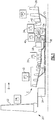
Figure 1 schematically shows a gas turbine engine. -
Figure 2 shows how a volume of the turbine section can be calculated. - A gas turbine engine 20 is illustrated in
Figure 1 , and incorporates afan 22 driven through agear reduction 24. Thegear reduction 24 is driven with alow speed spool 25 by a fan/gear drive turbine ("FGDT") 26. Air is delivered from the fan as bypass air B, and into alow pressure compressor 30 as core air C. The air compressed by thelow pressure compressor 30 passes downstream into ahigh pressure compressor 36, and then into acombustion section 28. From thecombustion section 28, gases pass across ahigh pressure turbine 40,low pressure turbine 34, and fan/gear drive turbine 26. - A plurality of vanes and
stators low pressure compressor 30 rotates with anintermediate pressure spool 32 and theturbine 34 in a first ("+") direction. Thefan drive turbine 26 rotates with ashaft 25 in the same ("+") direction as thelow pressure spool 32. Thespeed change gear 24 may cause thefan 22 to rotate in the opposite ("-") direction. However, the fan rotating in the same direction would come within the scope of this invention. As is known within the art and as illustrated, a star gear arrangement may be utilized for the fan to rotate in an opposite direction as to the fan/gear drive turbine 26. On the other hand, a planetary gear arrangement may be utilized, wherein the two rotate in the same direction. Thehigh pressure compressor 36 rotates with aspool 38 and is driven by ahigh pressure turbine 40 in the direction ("+") as to thespool 32 andshaft 25. - Since the
turbines vanes vane 50 may be incorporated into a mid-turbine frame (as an air turning mid-turbine frame ("tmtf') vane) which also provides a support for the highpressure turbine rotor 40 or may be a separate vane. - The
fan drive turbine 26 in this arrangement can operate at a higher speed than other fan drive turbine arrangements. The fan drive turbine can have shrouded blades, which provides design freedom. - The low pressure compressor may have more than three stages. The fan drive turbine has at least two, and up to six stages. The high pressure turbine as illustrated may have one or two stages, and the low pressure turbine may have one or two stages.
- The above features achieve a more compact turbine section volume relative to the prior art, including both the high and low pressure turbines. A range of materials can be selected. As one example, by varying the materials for forming the low pressure turbine, the volume can be reduced through the use of more expensive and more exotic engineered materials, or alternatively, lower priced materials can be utilized. In three exemplary embodiments the first rotating blade of the fan drive turbine can be a directionally solidified casting blade, a single crystal casting blade or a hollow, internally cooled blade. All three embodiments will change the turbine volume to be dramatically smaller than the prior art by increasing low pressure turbine speed.
- Due to the compact turbine section, a power density, which may be defined as thrust in pounds force produced divided by the volume of the entire turbine section, may be optimized. The volume of the turbine section may be defined by an inlet of a first turbine vane in the high pressure turbine to the exit of the last rotating airfoil in the fan/
gear drive turbine 26, and may be expressed in cubic inches. The static thrust at the engine's flat rated Sea Level Takeoff condition divided by a turbine section volume is defined as power density. The sea level take-off flat-rated static thrust may be defined in pounds force, while the volume may be the volume from the annular inlet of the first turbine vane in the high pressure turbine to the annular exit of the downstream end of the last rotor section in the fan drive turbine. The maximum thrust may be sea level take-off thrust "SLTO thrust" which is commonly defined as the flat-rated static thrust produced by the turbofan at sea-level. - The volume V of the turbine section may be best understood from
Figure 2 . The high pressure turbine rotor is illustrated at 40, the low pressure turbine rotor at 34, and the fan drive turbine rotor at 26. The volume V is illustrated by dashed line, and extends from an inner periphery I to an outer periphery O. The inner periphery is somewhat defined by the flowpath of the rotors, but also by the inner platform flow paths of vanes. The outer periphery is defined by the stator vanes and outer air seal structures along the flowpath. The volume extends from a most upstream 400 end of the mostupstream blade 410 in highpressure turbine section 40, typically its leading edge, and to the mostdownstream edge 401 of the lastrotating airfoil 412 in the fandrive turbine section 26. Typically, this will be the trailing edge of that airfoil. Mid-turbine frames and vanes as illustrated inFigure 1 may be included. - The power density in the disclosed gas turbine engine is much higher than in the prior art. Eight exemplary engines are shown below which incorporate turbine sections and overall engine drive systems and architectures as set forth in this application, and can be found in Table I as follows:
TABLE 1 Engine Thrust SLTO (lbf) Turbine section volume from the Inlet Thrust/turbine section volume (lbf/in3) 1 17,000 3,859 4.4 2 23,300 5,330 4.37 3 29,500 6,745 4.37 4 33,000 6,745 4.84 5 96,500 31,086 3.1 6 96,500 62,172 1.55 7 96,500 46,629 2.07 8 37,098 6,745 5.50 - Thus, in embodiments, the power density would be greater than or equal to about 1.5 lbf/in3. More narrowly, the power density would be greater than or equal to about 2.0 lbf/in3.
- Even more narrowly, the power density would be greater than or equal to about 3.0 lbf/in3.
- More narrowly, the power density is greater than or equal to about 4.0 lbf/in3.
- Also, in embodiments, the power density is less than or equal to about 5.5 lbf/in3.
- The engine 20 in one example is a high-bypass geared aircraft engine. The bypass ratio is the amount of air delivered into bypass path B divided by the amount of air into core path C. In a further example, the engine 20 bypass ratio is greater than about six (6), with an example embodiment being greater than ten (10), the geared
architecture 24 is an epicyclic gear train, such as a star gear system or other gear system, with a gear reduction ratio of greater than about 2.3 and the fan/geardrive turbine section 26 has a pressure ratio that is greater than about 5. In one disclosed embodiment, the engine 20 bypass ratio is greater than about ten (10:1), the fan diameter is significantly larger than that of the lowpressure compressor section 30, and the fan/geardrive turbine section 26 has a pressure ratio that is greater than about 5:1. In some embodiments, the highpressure turbine section 40 may have two or fewer stages. In contrast, the fan/geardrive turbine section 26, in some embodiments, has between two and six stages. Further the fan/geardrive turbine section 26 pressure ratio is total pressure measured prior to inlet of fan/geardrive turbine section 26 as related to the total pressure at the outlet of the fan/geardrive turbine section 26 prior to an exhaust nozzle. The gearedarchitecture 24 may be an epicycle gear train, such as a planetary gear system or other gear system, with a gear reduction ratio of greater than about 2.5:1. It should be understood, however, that the above parameters are only exemplary of one embodiment of a geared architecture engine and that the present invention is applicable to other gas turbine engines including direct drive turbofans. - A significant amount of thrust is provided by the bypass flow B due to the high bypass ratio. The
fan section 22 of the engine 20 is designed for a particular flight condition -- typically cruise at about 0.8 Mach and about 35,000 feet. The flight condition of 0.8 Mach and 35,000 ft, with the engine at its best fuel consumption - also known as "bucket cruise Thrust Specific Fuel Consumption ("TSFC"). TSFC is the industry standard parameter of the rate of lbm of fuel being burned per hour divided by lbf of thrust the engine produces at that flight condition. "Low fan pressure ratio" is the ratio of total pressure across the fan blade alone, before the fan exit guide vanes. The low fan pressure ratio as disclosed herein according to one non-limiting embodiment is less than about 1.45. "Low corrected fan tip speed" is the actual fan tip speed in ft/sec divided by an industry standard temperature correction of [(Ram Air Temperature deg R) / 518.7)^0.5]. The "Low corrected fan tip speed" as disclosed herein according to one non-limiting embodiment is less than about 1150 ft / second. Further, thefan 22 may have 26 or fewer blades. - Engines made with the disclosed architecture, and including turbine sections as set forth in this application, and with modifications coming from the scope of the claims in this application, thus provide very high efficient operation, and increased fuel efficiency and lightweight relative to their trust capability.
- Although an embodiment of this invention has been disclosed, a worker of ordinary skill in this art would recognize that certain modifications would come within the scope of this invention. For that reason, the following claims should be studied to determine the true scope and content of this invention.
Claims (9)
- A gas turbine engine comprising:a fan rotor, a first compressor rotor and a second compressor rotor, said second compressor rotor compressing air to a higher pressure than said first compressor rotor;a first turbine rotor, said first turbine rotor driving said second compressor rotor, and a second turbine rotor, said second turbine driving said first compressor rotor;a fan drive turbine positioned downstream of said second turbine rotor, said fan drive turbine driving said fan rotor through a gear reduction; andsaid first compressor rotor and said second turbine rotor rotating as an intermediate speed spool, and said second compressor rotor and said first turbine rotor rotating together as a high speed spool, with said high speed spool, said intermediate speed spool, and said fan drive turbine rotating in the same direction.
- The engine as set forth in claim 1, wherein said fan rotor is driven by said gear reduction to rotate in the same direction as said fan drive turbine.
- The engine as set forth in claim 1 or 2, wherein a power density of the engine is greater than or equal to about 1.5 lbs/in3 and less than or equal to about 5.5 lbf/in3, said power density is defined as a ratio of thrust produced by said engine expressed in pounds force to a volume of a turbine section incorporating each of said first turbine rotor, said second turbine rotor and said fan drive turbine rotor, expressed in cubic inches, and said thrust is sea level take-off flat-rated static thrust.
- The engine as set forth in claim 3, wherein said ratio is greater than or equal to 2.0.
- The engine as set forth in claim 4, wherein said ratio is greater than or equal to about 4.0.
- The engine as set forth in any preceding claim, wherein said fan rotor delivers a portion of air into a bypass duct and a portion of air into said first compressor rotor as core flow.
- The engine as set forth in any preceding claim, wherein a mid-turbine frame is positioned between said first and second turbine rotors.
- The engine as set forth in claim 7, wherein a vane is positioned between said mid-turbine frame and said second turbine rotor.
- The engine as set forth in any preceding claim, wherein a vane is positioned between said second turbine rotor and said fan drive turbine.
Applications Claiming Priority (3)
| Application Number | Priority Date | Filing Date | Title |
|---|---|---|---|
| US13/437,304 US10036351B2 (en) | 2012-04-02 | 2012-04-02 | Geared turbofan with three co-rotating turbines |
| EP13813981.1A EP2834493B1 (en) | 2012-04-02 | 2013-03-29 | Geared turbofan with three co-rotating turbines |
| PCT/US2013/034537 WO2014007896A2 (en) | 2012-04-02 | 2013-03-29 | Geared turbofan with three co-rotating turbines |
Related Parent Applications (1)
| Application Number | Title | Priority Date | Filing Date |
|---|---|---|---|
| EP13813981.1A Division EP2834493B1 (en) | 2012-04-02 | 2013-03-29 | Geared turbofan with three co-rotating turbines |
Publications (2)
| Publication Number | Publication Date |
|---|---|
| EP3591190A1 true EP3591190A1 (en) | 2020-01-08 |
| EP3591190B1 EP3591190B1 (en) | 2023-09-06 |
Family
ID=49233012
Family Applications (2)
| Application Number | Title | Priority Date | Filing Date |
|---|---|---|---|
| EP13813981.1A Active EP2834493B1 (en) | 2012-04-02 | 2013-03-29 | Geared turbofan with three co-rotating turbines |
| EP19186606.0A Active EP3591190B1 (en) | 2012-04-02 | 2013-03-29 | Geared turbofan with three co-rotating turbines |
Family Applications Before (1)
| Application Number | Title | Priority Date | Filing Date |
|---|---|---|---|
| EP13813981.1A Active EP2834493B1 (en) | 2012-04-02 | 2013-03-29 | Geared turbofan with three co-rotating turbines |
Country Status (4)
| Country | Link |
|---|---|
| US (1) | US10036351B2 (en) |
| EP (2) | EP2834493B1 (en) |
| SG (1) | SG11201405924VA (en) |
| WO (1) | WO2014007896A2 (en) |
Families Citing this family (19)
| Publication number | Priority date | Publication date | Assignee | Title |
|---|---|---|---|---|
| US11149650B2 (en) * | 2007-08-01 | 2021-10-19 | Raytheon Technologies Corporation | Turbine section of high bypass turbofan |
| US11486311B2 (en) * | 2007-08-01 | 2022-11-01 | Raytheon Technologies Corporation | Turbine section of high bypass turbofan |
| US11242805B2 (en) * | 2007-08-01 | 2022-02-08 | Raytheon Technologies Corporation | Turbine section of high bypass turbofan |
| US20150377123A1 (en) | 2007-08-01 | 2015-12-31 | United Technologies Corporation | Turbine section of high bypass turbofan |
| US20160130949A1 (en) | 2012-01-31 | 2016-05-12 | United Technologies Corporation | Low noise turbine for geared turbofan engine |
| US20150204238A1 (en) * | 2012-01-31 | 2015-07-23 | United Technologies Corporation | Low noise turbine for geared turbofan engine |
| US8935913B2 (en) | 2012-01-31 | 2015-01-20 | United Technologies Corporation | Geared turbofan gas turbine engine architecture |
| US20130192191A1 (en) | 2012-01-31 | 2013-08-01 | Frederick M. Schwarz | Gas turbine engine with high speed low pressure turbine section and bearing support features |
| US20150345426A1 (en) | 2012-01-31 | 2015-12-03 | United Technologies Corporation | Geared turbofan gas turbine engine architecture |
| US10287914B2 (en) | 2012-01-31 | 2019-05-14 | United Technologies Corporation | Gas turbine engine with high speed low pressure turbine section and bearing support features |
| US10125693B2 (en) | 2012-04-02 | 2018-11-13 | United Technologies Corporation | Geared turbofan engine with power density range |
| US10138809B2 (en) | 2012-04-02 | 2018-11-27 | United Technologies Corporation | Geared turbofan engine with a high ratio of thrust to turbine volume |
| US11719161B2 (en) | 2013-03-14 | 2023-08-08 | Raytheon Technologies Corporation | Low noise turbine for geared gas turbine engine |
| US10605172B2 (en) | 2013-03-14 | 2020-03-31 | United Technologies Corporation | Low noise turbine for geared gas turbine engine |
| CA2879244C (en) * | 2014-01-21 | 2018-04-03 | United Technologies Corporation | Low noise compressor rotor for geared turbofan engine |
| CA2916866C (en) * | 2015-01-09 | 2020-02-18 | United Technologies Corporation | Geared turbofan engine with power density range |
| CA2915343A1 (en) * | 2015-01-09 | 2016-07-09 | Frederick M. Schwarz | Geared turbofan engine with a high ratio of thrust to turbine volume |
| CA2923331A1 (en) * | 2015-03-19 | 2016-09-19 | David P. Houston | Geared turbofan gas turbine engine architecture |
| CN112196671B (en) * | 2020-09-18 | 2021-08-20 | 中国航发四川燃气涡轮研究院 | Adjustable internal and external culvert force transmission mechanism |
Citations (3)
| Publication number | Priority date | Publication date | Assignee | Title |
|---|---|---|---|---|
| US4651521A (en) * | 1985-11-21 | 1987-03-24 | Avco Corporation | Convertible turbo-fan, turbo-shaft aircraft propulsion system |
| US20060288686A1 (en) * | 2005-06-06 | 2006-12-28 | General Electric Company | Counterrotating turbofan engine |
| DE102006021436A1 (en) * | 2006-05-09 | 2007-11-15 | Mtu Aero Engines Gmbh | Gas turbine engine |
Family Cites Families (22)
| Publication number | Priority date | Publication date | Assignee | Title |
|---|---|---|---|---|
| US3287906A (en) | 1965-07-20 | 1966-11-29 | Gen Motors Corp | Cooled gas turbine vanes |
| GB1436796A (en) * | 1972-08-22 | 1976-05-26 | Mtu Muenchen Gmbh | Gas turbine ducted fan engines of multi-shaft and multi-flow construction |
| GB1516041A (en) | 1977-02-14 | 1978-06-28 | Secr Defence | Multistage axial flow compressor stators |
| GB2041090A (en) | 1979-01-31 | 1980-09-03 | Rolls Royce | By-pass gas turbine engines |
| US5160251A (en) | 1991-05-13 | 1992-11-03 | General Electric Company | Lightweight engine turbine bearing support assembly for withstanding radial and axial loads |
| US5388964A (en) | 1993-09-14 | 1995-02-14 | General Electric Company | Hybrid rotor blade |
| WO1997000381A1 (en) | 1994-12-14 | 1997-01-03 | United Technologies Corporation | Compressor stall and surge control using airflow asymmetry measurement |
| US5806303A (en) | 1996-03-29 | 1998-09-15 | General Electric Company | Turbofan engine with a core driven supercharged bypass duct and fixed geometry nozzle |
| EP1780387A3 (en) | 2000-09-05 | 2007-07-18 | Sudarshan Paul Dev | Nested core gas turbine engine |
| US6732502B2 (en) | 2002-03-01 | 2004-05-11 | General Electric Company | Counter rotating aircraft gas turbine engine with high overall pressure ratio compressor |
| FR2866387B1 (en) | 2004-02-12 | 2008-03-14 | Snecma Moteurs | AERODYNAMIC ADAPTATION OF THE BACK BLOW OF A DOUBLE BLOWER TURBOREACTOR |
| EP1928952B1 (en) | 2005-09-28 | 2014-07-09 | Entrotech Composites, LLC. | Braid-reinforced composites and processes for their preparation |
| US7594404B2 (en) | 2006-07-27 | 2009-09-29 | United Technologies Corporation | Embedded mount for mid-turbine frame |
| US7632064B2 (en) * | 2006-09-01 | 2009-12-15 | United Technologies Corporation | Variable geometry guide vane for a gas turbine engine |
| US7905083B2 (en) * | 2006-10-31 | 2011-03-15 | General Electric Company | Turbofan engine assembly and method of assembling same |
| US8017188B2 (en) | 2007-04-17 | 2011-09-13 | General Electric Company | Methods of making articles having toughened and untoughened regions |
| US8015798B2 (en) | 2007-12-13 | 2011-09-13 | United Technologies Corporation | Geared counter-rotating gas turbofan engine |
| US8887485B2 (en) * | 2008-10-20 | 2014-11-18 | Rolls-Royce North American Technologies, Inc. | Three spool gas turbine engine having a clutch and compressor bypass |
| US8191352B2 (en) | 2008-12-19 | 2012-06-05 | General Electric Company | Geared differential speed counter-rotatable low pressure turbine |
| US8172716B2 (en) | 2009-06-25 | 2012-05-08 | United Technologies Corporation | Epicyclic gear system with superfinished journal bearing |
| US8176725B2 (en) | 2009-09-09 | 2012-05-15 | United Technologies Corporation | Reversed-flow core for a turbofan with a fan drive gear system |
| US8887487B2 (en) * | 2012-01-31 | 2014-11-18 | United Technologies Corporation | Geared turbofan gas turbine engine architecture |
-
2012
- 2012-04-02 US US13/437,304 patent/US10036351B2/en active Active
-
2013
- 2013-03-29 EP EP13813981.1A patent/EP2834493B1/en active Active
- 2013-03-29 WO PCT/US2013/034537 patent/WO2014007896A2/en not_active Ceased
- 2013-03-29 EP EP19186606.0A patent/EP3591190B1/en active Active
- 2013-03-29 SG SG11201405924VA patent/SG11201405924VA/en unknown
Patent Citations (3)
| Publication number | Priority date | Publication date | Assignee | Title |
|---|---|---|---|---|
| US4651521A (en) * | 1985-11-21 | 1987-03-24 | Avco Corporation | Convertible turbo-fan, turbo-shaft aircraft propulsion system |
| US20060288686A1 (en) * | 2005-06-06 | 2006-12-28 | General Electric Company | Counterrotating turbofan engine |
| DE102006021436A1 (en) * | 2006-05-09 | 2007-11-15 | Mtu Aero Engines Gmbh | Gas turbine engine |
Also Published As
| Publication number | Publication date |
|---|---|
| US20130255219A1 (en) | 2013-10-03 |
| WO2014007896A2 (en) | 2014-01-09 |
| US10036351B2 (en) | 2018-07-31 |
| EP2834493B1 (en) | 2019-07-17 |
| EP3591190B1 (en) | 2023-09-06 |
| SG11201405924VA (en) | 2014-10-30 |
| EP2834493A4 (en) | 2015-04-15 |
| WO2014007896A3 (en) | 2014-04-10 |
| EP2834493A2 (en) | 2015-02-11 |
Similar Documents
| Publication | Publication Date | Title |
|---|---|---|
| US10830130B2 (en) | Geared turbofan with three turbines all counter-rotating | |
| EP3591190B1 (en) | Geared turbofan with three co-rotating turbines | |
| US11970984B2 (en) | Gas turbine engine with power density range | |
| EP2834466B1 (en) | Geared turbofan with three turbines with first two co-rotating and third rotating in an opposed direction | |
| US11053843B2 (en) | Geared turbofan engine with a high ratio of thrust to turbine volume | |
| US10036350B2 (en) | Geared turbofan with three turbines all co-rotating | |
| EP2834469B1 (en) | Geared turbofan with three turbines with first two counter-rotating, and third co-rotating with the second turbine | |
| US20130259653A1 (en) | Geared turbofan engine with power density range | |
| US20130259643A1 (en) | Geared turbofan with three turbines with first two counter-rotating, and third co-rotating with the second turbine | |
| EP2834494B1 (en) | Geared turbofan engine | |
| EP3043058A1 (en) | Geared turbofan engine with power density range | |
| EP3043034A1 (en) | Geared turbofan engine with a high ratio of thrust to turbine volume |
Legal Events
| Date | Code | Title | Description |
|---|---|---|---|
| PUAI | Public reference made under article 153(3) epc to a published international application that has entered the european phase |
Free format text: ORIGINAL CODE: 0009012 |
|
| STAA | Information on the status of an ep patent application or granted ep patent |
Free format text: STATUS: THE APPLICATION HAS BEEN PUBLISHED |
|
| AC | Divisional application: reference to earlier application |
Ref document number: 2834493 Country of ref document: EP Kind code of ref document: P |
|
| AK | Designated contracting states |
Kind code of ref document: A1 Designated state(s): AL AT BE BG CH CY CZ DE DK EE ES FI FR GB GR HR HU IE IS IT LI LT LU LV MC MK MT NL NO PL PT RO RS SE SI SK SM TR |
|
| STAA | Information on the status of an ep patent application or granted ep patent |
Free format text: STATUS: REQUEST FOR EXAMINATION WAS MADE |
|
| 17P | Request for examination filed |
Effective date: 20200708 |
|
| RBV | Designated contracting states (corrected) |
Designated state(s): AL AT BE BG CH CY CZ DE DK EE ES FI FR GB GR HR HU IE IS IT LI LT LU LV MC MK MT NL NO PL PT RO RS SE SI SK SM TR |
|
| RAP1 | Party data changed (applicant data changed or rights of an application transferred) |
Owner name: RAYTHEON TECHNOLOGIES CORPORATION |
|
| STAA | Information on the status of an ep patent application or granted ep patent |
Free format text: STATUS: EXAMINATION IS IN PROGRESS |
|
| 17Q | First examination report despatched |
Effective date: 20220112 |
|
| GRAP | Despatch of communication of intention to grant a patent |
Free format text: ORIGINAL CODE: EPIDOSNIGR1 |
|
| STAA | Information on the status of an ep patent application or granted ep patent |
Free format text: STATUS: GRANT OF PATENT IS INTENDED |
|
| INTG | Intention to grant announced |
Effective date: 20230317 |
|
| GRAS | Grant fee paid |
Free format text: ORIGINAL CODE: EPIDOSNIGR3 |
|
| GRAA | (expected) grant |
Free format text: ORIGINAL CODE: 0009210 |
|
| STAA | Information on the status of an ep patent application or granted ep patent |
Free format text: STATUS: THE PATENT HAS BEEN GRANTED |
|
| AC | Divisional application: reference to earlier application |
Ref document number: 2834493 Country of ref document: EP Kind code of ref document: P |
|
| AK | Designated contracting states |
Kind code of ref document: B1 Designated state(s): AL AT BE BG CH CY CZ DE DK EE ES FI FR GB GR HR HU IE IS IT LI LT LU LV MC MK MT NL NO PL PT RO RS SE SI SK SM TR |
|
| REG | Reference to a national code |
Ref country code: GB Ref legal event code: FG4D |
|
| REG | Reference to a national code |
Ref country code: CH Ref legal event code: EP |
|
| REG | Reference to a national code |
Ref country code: DE Ref legal event code: R096 Ref document number: 602013084621 Country of ref document: DE |
|
| REG | Reference to a national code |
Ref country code: IE Ref legal event code: FG4D |
|
| RAP4 | Party data changed (patent owner data changed or rights of a patent transferred) |
Owner name: RTX CORPORATION |
|
| REG | Reference to a national code |
Ref country code: LT Ref legal event code: MG9D |
|
| REG | Reference to a national code |
Ref country code: NL Ref legal event code: MP Effective date: 20230906 |
|
| PG25 | Lapsed in a contracting state [announced via postgrant information from national office to epo] |
Ref country code: GR Free format text: LAPSE BECAUSE OF FAILURE TO SUBMIT A TRANSLATION OF THE DESCRIPTION OR TO PAY THE FEE WITHIN THE PRESCRIBED TIME-LIMIT Effective date: 20231207 |
|
| PG25 | Lapsed in a contracting state [announced via postgrant information from national office to epo] |
Ref country code: SE Free format text: LAPSE BECAUSE OF FAILURE TO SUBMIT A TRANSLATION OF THE DESCRIPTION OR TO PAY THE FEE WITHIN THE PRESCRIBED TIME-LIMIT Effective date: 20230906 Ref country code: RS Free format text: LAPSE BECAUSE OF FAILURE TO SUBMIT A TRANSLATION OF THE DESCRIPTION OR TO PAY THE FEE WITHIN THE PRESCRIBED TIME-LIMIT Effective date: 20230906 Ref country code: NO Free format text: LAPSE BECAUSE OF FAILURE TO SUBMIT A TRANSLATION OF THE DESCRIPTION OR TO PAY THE FEE WITHIN THE PRESCRIBED TIME-LIMIT Effective date: 20231206 Ref country code: LV Free format text: LAPSE BECAUSE OF FAILURE TO SUBMIT A TRANSLATION OF THE DESCRIPTION OR TO PAY THE FEE WITHIN THE PRESCRIBED TIME-LIMIT Effective date: 20230906 Ref country code: LT Free format text: LAPSE BECAUSE OF FAILURE TO SUBMIT A TRANSLATION OF THE DESCRIPTION OR TO PAY THE FEE WITHIN THE PRESCRIBED TIME-LIMIT Effective date: 20230906 Ref country code: HR Free format text: LAPSE BECAUSE OF FAILURE TO SUBMIT A TRANSLATION OF THE DESCRIPTION OR TO PAY THE FEE WITHIN THE PRESCRIBED TIME-LIMIT Effective date: 20230906 Ref country code: GR Free format text: LAPSE BECAUSE OF FAILURE TO SUBMIT A TRANSLATION OF THE DESCRIPTION OR TO PAY THE FEE WITHIN THE PRESCRIBED TIME-LIMIT Effective date: 20231207 Ref country code: FI Free format text: LAPSE BECAUSE OF FAILURE TO SUBMIT A TRANSLATION OF THE DESCRIPTION OR TO PAY THE FEE WITHIN THE PRESCRIBED TIME-LIMIT Effective date: 20230906 |
|
| REG | Reference to a national code |
Ref country code: AT Ref legal event code: MK05 Ref document number: 1608837 Country of ref document: AT Kind code of ref document: T Effective date: 20230906 |
|
| PG25 | Lapsed in a contracting state [announced via postgrant information from national office to epo] |
Ref country code: NL Free format text: LAPSE BECAUSE OF FAILURE TO SUBMIT A TRANSLATION OF THE DESCRIPTION OR TO PAY THE FEE WITHIN THE PRESCRIBED TIME-LIMIT Effective date: 20230906 |
|
| PG25 | Lapsed in a contracting state [announced via postgrant information from national office to epo] |
Ref country code: IS Free format text: LAPSE BECAUSE OF FAILURE TO SUBMIT A TRANSLATION OF THE DESCRIPTION OR TO PAY THE FEE WITHIN THE PRESCRIBED TIME-LIMIT Effective date: 20240106 |
|
| PG25 | Lapsed in a contracting state [announced via postgrant information from national office to epo] |
Ref country code: AT Free format text: LAPSE BECAUSE OF FAILURE TO SUBMIT A TRANSLATION OF THE DESCRIPTION OR TO PAY THE FEE WITHIN THE PRESCRIBED TIME-LIMIT Effective date: 20230906 |
|
| PG25 | Lapsed in a contracting state [announced via postgrant information from national office to epo] |
Ref country code: ES Free format text: LAPSE BECAUSE OF FAILURE TO SUBMIT A TRANSLATION OF THE DESCRIPTION OR TO PAY THE FEE WITHIN THE PRESCRIBED TIME-LIMIT Effective date: 20230906 |
|
| PG25 | Lapsed in a contracting state [announced via postgrant information from national office to epo] |
Ref country code: SM Free format text: LAPSE BECAUSE OF FAILURE TO SUBMIT A TRANSLATION OF THE DESCRIPTION OR TO PAY THE FEE WITHIN THE PRESCRIBED TIME-LIMIT Effective date: 20230906 Ref country code: RO Free format text: LAPSE BECAUSE OF FAILURE TO SUBMIT A TRANSLATION OF THE DESCRIPTION OR TO PAY THE FEE WITHIN THE PRESCRIBED TIME-LIMIT Effective date: 20230906 Ref country code: IS Free format text: LAPSE BECAUSE OF FAILURE TO SUBMIT A TRANSLATION OF THE DESCRIPTION OR TO PAY THE FEE WITHIN THE PRESCRIBED TIME-LIMIT Effective date: 20240106 Ref country code: ES Free format text: LAPSE BECAUSE OF FAILURE TO SUBMIT A TRANSLATION OF THE DESCRIPTION OR TO PAY THE FEE WITHIN THE PRESCRIBED TIME-LIMIT Effective date: 20230906 Ref country code: EE Free format text: LAPSE BECAUSE OF FAILURE TO SUBMIT A TRANSLATION OF THE DESCRIPTION OR TO PAY THE FEE WITHIN THE PRESCRIBED TIME-LIMIT Effective date: 20230906 Ref country code: CZ Free format text: LAPSE BECAUSE OF FAILURE TO SUBMIT A TRANSLATION OF THE DESCRIPTION OR TO PAY THE FEE WITHIN THE PRESCRIBED TIME-LIMIT Effective date: 20230906 Ref country code: AT Free format text: LAPSE BECAUSE OF FAILURE TO SUBMIT A TRANSLATION OF THE DESCRIPTION OR TO PAY THE FEE WITHIN THE PRESCRIBED TIME-LIMIT Effective date: 20230906 Ref country code: SK Free format text: LAPSE BECAUSE OF FAILURE TO SUBMIT A TRANSLATION OF THE DESCRIPTION OR TO PAY THE FEE WITHIN THE PRESCRIBED TIME-LIMIT Effective date: 20230906 Ref country code: PT Free format text: LAPSE BECAUSE OF FAILURE TO SUBMIT A TRANSLATION OF THE DESCRIPTION OR TO PAY THE FEE WITHIN THE PRESCRIBED TIME-LIMIT Effective date: 20240108 |
|
| PG25 | Lapsed in a contracting state [announced via postgrant information from national office to epo] |
Ref country code: PL Free format text: LAPSE BECAUSE OF FAILURE TO SUBMIT A TRANSLATION OF THE DESCRIPTION OR TO PAY THE FEE WITHIN THE PRESCRIBED TIME-LIMIT Effective date: 20230906 Ref country code: IT Free format text: LAPSE BECAUSE OF FAILURE TO SUBMIT A TRANSLATION OF THE DESCRIPTION OR TO PAY THE FEE WITHIN THE PRESCRIBED TIME-LIMIT Effective date: 20230906 |
|
| REG | Reference to a national code |
Ref country code: DE Ref legal event code: R097 Ref document number: 602013084621 Country of ref document: DE |
|
| PG25 | Lapsed in a contracting state [announced via postgrant information from national office to epo] |
Ref country code: DK Free format text: LAPSE BECAUSE OF FAILURE TO SUBMIT A TRANSLATION OF THE DESCRIPTION OR TO PAY THE FEE WITHIN THE PRESCRIBED TIME-LIMIT Effective date: 20230906 |
|
| PLBE | No opposition filed within time limit |
Free format text: ORIGINAL CODE: 0009261 |
|
| STAA | Information on the status of an ep patent application or granted ep patent |
Free format text: STATUS: NO OPPOSITION FILED WITHIN TIME LIMIT |
|
| PG25 | Lapsed in a contracting state [announced via postgrant information from national office to epo] |
Ref country code: DK Free format text: LAPSE BECAUSE OF FAILURE TO SUBMIT A TRANSLATION OF THE DESCRIPTION OR TO PAY THE FEE WITHIN THE PRESCRIBED TIME-LIMIT Effective date: 20230906 Ref country code: SI Free format text: LAPSE BECAUSE OF FAILURE TO SUBMIT A TRANSLATION OF THE DESCRIPTION OR TO PAY THE FEE WITHIN THE PRESCRIBED TIME-LIMIT Effective date: 20230906 |
|
| 26N | No opposition filed |
Effective date: 20240607 |
|
| REG | Reference to a national code |
Ref country code: CH Ref legal event code: PL |
|
| PG25 | Lapsed in a contracting state [announced via postgrant information from national office to epo] |
Ref country code: BG Free format text: LAPSE BECAUSE OF FAILURE TO SUBMIT A TRANSLATION OF THE DESCRIPTION OR TO PAY THE FEE WITHIN THE PRESCRIBED TIME-LIMIT Effective date: 20230906 |
|
| PG25 | Lapsed in a contracting state [announced via postgrant information from national office to epo] |
Ref country code: LU Free format text: LAPSE BECAUSE OF NON-PAYMENT OF DUE FEES Effective date: 20240329 |
|
| PG25 | Lapsed in a contracting state [announced via postgrant information from national office to epo] |
Ref country code: MC Free format text: LAPSE BECAUSE OF FAILURE TO SUBMIT A TRANSLATION OF THE DESCRIPTION OR TO PAY THE FEE WITHIN THE PRESCRIBED TIME-LIMIT Effective date: 20230906 |
|
| PG25 | Lapsed in a contracting state [announced via postgrant information from national office to epo] |
Ref country code: MC Free format text: LAPSE BECAUSE OF FAILURE TO SUBMIT A TRANSLATION OF THE DESCRIPTION OR TO PAY THE FEE WITHIN THE PRESCRIBED TIME-LIMIT Effective date: 20230906 Ref country code: LU Free format text: LAPSE BECAUSE OF NON-PAYMENT OF DUE FEES Effective date: 20240329 Ref country code: BG Free format text: LAPSE BECAUSE OF FAILURE TO SUBMIT A TRANSLATION OF THE DESCRIPTION OR TO PAY THE FEE WITHIN THE PRESCRIBED TIME-LIMIT Effective date: 20230906 |
|
| REG | Reference to a national code |
Ref country code: BE Ref legal event code: MM Effective date: 20240331 |
|
| PG25 | Lapsed in a contracting state [announced via postgrant information from national office to epo] |
Ref country code: BE Free format text: LAPSE BECAUSE OF NON-PAYMENT OF DUE FEES Effective date: 20240331 |
|
| PG25 | Lapsed in a contracting state [announced via postgrant information from national office to epo] |
Ref country code: IE Free format text: LAPSE BECAUSE OF NON-PAYMENT OF DUE FEES Effective date: 20240329 |
|
| PG25 | Lapsed in a contracting state [announced via postgrant information from national office to epo] |
Ref country code: BE Free format text: LAPSE BECAUSE OF NON-PAYMENT OF DUE FEES Effective date: 20240331 Ref country code: IE Free format text: LAPSE BECAUSE OF NON-PAYMENT OF DUE FEES Effective date: 20240329 Ref country code: CH Free format text: LAPSE BECAUSE OF NON-PAYMENT OF DUE FEES Effective date: 20240331 |
|
| PG25 | Lapsed in a contracting state [announced via postgrant information from national office to epo] |
Ref country code: CY Free format text: LAPSE BECAUSE OF FAILURE TO SUBMIT A TRANSLATION OF THE DESCRIPTION OR TO PAY THE FEE WITHIN THE PRESCRIBED TIME-LIMIT; INVALID AB INITIO Effective date: 20130329 |
|
| PG25 | Lapsed in a contracting state [announced via postgrant information from national office to epo] |
Ref country code: HU Free format text: LAPSE BECAUSE OF FAILURE TO SUBMIT A TRANSLATION OF THE DESCRIPTION OR TO PAY THE FEE WITHIN THE PRESCRIBED TIME-LIMIT; INVALID AB INITIO Effective date: 20130329 |
|
| REG | Reference to a national code |
Ref country code: DE Ref legal event code: R081 Ref document number: 602013084621 Country of ref document: DE Owner name: RTX CORPORATION (N.D.GES.D. STAATES DELAWARE),, US Free format text: FORMER OWNER: RAYTHEON TECHNOLOGIES CORPORATION, FARMINGTON, CT, US |
|
| PG25 | Lapsed in a contracting state [announced via postgrant information from national office to epo] |
Ref country code: TR Free format text: LAPSE BECAUSE OF FAILURE TO SUBMIT A TRANSLATION OF THE DESCRIPTION OR TO PAY THE FEE WITHIN THE PRESCRIBED TIME-LIMIT Effective date: 20230906 |
|
| P01 | Opt-out of the competence of the unified patent court (upc) registered |
Free format text: CASE NUMBER: UPC_APP_0019301_3591190/2025 Effective date: 20251223 |
|
| PGFP | Annual fee paid to national office [announced via postgrant information from national office to epo] |
Ref country code: GB Payment date: 20260220 Year of fee payment: 14 |
|
| PGFP | Annual fee paid to national office [announced via postgrant information from national office to epo] |
Ref country code: DE Payment date: 20260219 Year of fee payment: 14 |
|
| PGFP | Annual fee paid to national office [announced via postgrant information from national office to epo] |
Ref country code: FR Payment date: 20260219 Year of fee payment: 14 |