EP3590838B1 - Antimicrobial surfaces for flow path components - Google Patents
Antimicrobial surfaces for flow path components Download PDFInfo
- Publication number
- EP3590838B1 EP3590838B1 EP19183902.6A EP19183902A EP3590838B1 EP 3590838 B1 EP3590838 B1 EP 3590838B1 EP 19183902 A EP19183902 A EP 19183902A EP 3590838 B1 EP3590838 B1 EP 3590838B1
- Authority
- EP
- European Patent Office
- Prior art keywords
- flow path
- flow
- path component
- antimicrobial nanoparticles
- nanoparticles
- Prior art date
- Legal status (The legal status is an assumption and is not a legal conclusion. Google has not performed a legal analysis and makes no representation as to the accuracy of the status listed.)
- Active
Links
Images


Classifications
-
- B—PERFORMING OPERATIONS; TRANSPORTING
- B32—LAYERED PRODUCTS
- B32B—LAYERED PRODUCTS, i.e. PRODUCTS BUILT-UP OF STRATA OF FLAT OR NON-FLAT, e.g. CELLULAR OR HONEYCOMB, FORM
- B32B5/00—Layered products characterised by the non- homogeneity or physical structure, i.e. comprising a fibrous, filamentary, particulate or foam layer; Layered products characterised by having a layer differing constitutionally or physically in different parts
- B32B5/16—Layered products characterised by the non- homogeneity or physical structure, i.e. comprising a fibrous, filamentary, particulate or foam layer; Layered products characterised by having a layer differing constitutionally or physically in different parts characterised by features of a layer formed of particles, e.g. chips, powder or granules
-
- B—PERFORMING OPERATIONS; TRANSPORTING
- B29—WORKING OF PLASTICS; WORKING OF SUBSTANCES IN A PLASTIC STATE IN GENERAL
- B29C—SHAPING OR JOINING OF PLASTICS; SHAPING OF MATERIAL IN A PLASTIC STATE, NOT OTHERWISE PROVIDED FOR; AFTER-TREATMENT OF THE SHAPED PRODUCTS, e.g. REPAIRING
- B29C64/00—Additive manufacturing, i.e. manufacturing of three-dimensional [3D] objects by additive deposition, additive agglomeration or additive layering, e.g. by 3D printing, stereolithography or selective laser sintering
- B29C64/10—Processes of additive manufacturing
- B29C64/106—Processes of additive manufacturing using only liquids or viscous materials, e.g. depositing a continuous bead of viscous material
- B29C64/118—Processes of additive manufacturing using only liquids or viscous materials, e.g. depositing a continuous bead of viscous material using filamentary material being melted, e.g. fused deposition modelling [FDM]
-
- B—PERFORMING OPERATIONS; TRANSPORTING
- B32—LAYERED PRODUCTS
- B32B—LAYERED PRODUCTS, i.e. PRODUCTS BUILT-UP OF STRATA OF FLAT OR NON-FLAT, e.g. CELLULAR OR HONEYCOMB, FORM
- B32B5/00—Layered products characterised by the non- homogeneity or physical structure, i.e. comprising a fibrous, filamentary, particulate or foam layer; Layered products characterised by having a layer differing constitutionally or physically in different parts
- B32B5/14—Layered products characterised by the non- homogeneity or physical structure, i.e. comprising a fibrous, filamentary, particulate or foam layer; Layered products characterised by having a layer differing constitutionally or physically in different parts characterised by a layer differing constitutionally or physically in different parts, e.g. denser near its faces
- B32B5/142—Variation across the area of the layer
-
- B—PERFORMING OPERATIONS; TRANSPORTING
- B32—LAYERED PRODUCTS
- B32B—LAYERED PRODUCTS, i.e. PRODUCTS BUILT-UP OF STRATA OF FLAT OR NON-FLAT, e.g. CELLULAR OR HONEYCOMB, FORM
- B32B7/00—Layered products characterised by the relation between layers; Layered products characterised by the relative orientation of features between layers, or by the relative values of a measurable parameter between layers, i.e. products comprising layers having different physical, chemical or physicochemical properties; Layered products characterised by the interconnection of layers
- B32B7/04—Interconnection of layers
- B32B7/12—Interconnection of layers using interposed adhesives or interposed materials with bonding properties
-
- B—PERFORMING OPERATIONS; TRANSPORTING
- B33—ADDITIVE MANUFACTURING TECHNOLOGY
- B33Y—ADDITIVE MANUFACTURING, i.e. MANUFACTURING OF THREE-DIMENSIONAL [3D] OBJECTS BY ADDITIVE DEPOSITION, ADDITIVE AGGLOMERATION OR ADDITIVE LAYERING, e.g. BY 3D PRINTING, STEREOLITHOGRAPHY OR SELECTIVE LASER SINTERING
- B33Y10/00—Processes of additive manufacturing
-
- B—PERFORMING OPERATIONS; TRANSPORTING
- B64—AIRCRAFT; AVIATION; COSMONAUTICS
- B64D—EQUIPMENT FOR FITTING IN OR TO AIRCRAFT; FLIGHT SUITS; PARACHUTES; ARRANGEMENT OR MOUNTING OF POWER PLANTS OR PROPULSION TRANSMISSIONS IN AIRCRAFT
- B64D13/00—Arrangements or adaptations of air-treatment apparatus for aircraft crew or passengers, or freight space
- B64D13/06—Arrangements or adaptations of air-treatment apparatus for aircraft crew or passengers, or freight space the air being conditioned
-
- F—MECHANICAL ENGINEERING; LIGHTING; HEATING; WEAPONS; BLASTING
- F28—HEAT EXCHANGE IN GENERAL
- F28F—DETAILS OF HEAT-EXCHANGE AND HEAT-TRANSFER APPARATUS, OF GENERAL APPLICATION
- F28F19/00—Preventing the formation of deposits or corrosion, e.g. by using filters or scrapers
- F28F19/02—Preventing the formation of deposits or corrosion, e.g. by using filters or scrapers by using coatings, e.g. vitreous or enamel coatings
-
- B—PERFORMING OPERATIONS; TRANSPORTING
- B29—WORKING OF PLASTICS; WORKING OF SUBSTANCES IN A PLASTIC STATE IN GENERAL
- B29C—SHAPING OR JOINING OF PLASTICS; SHAPING OF MATERIAL IN A PLASTIC STATE, NOT OTHERWISE PROVIDED FOR; AFTER-TREATMENT OF THE SHAPED PRODUCTS, e.g. REPAIRING
- B29C64/00—Additive manufacturing, i.e. manufacturing of three-dimensional [3D] objects by additive deposition, additive agglomeration or additive layering, e.g. by 3D printing, stereolithography or selective laser sintering
- B29C64/10—Processes of additive manufacturing
- B29C64/106—Processes of additive manufacturing using only liquids or viscous materials, e.g. depositing a continuous bead of viscous material
- B29C64/124—Processes of additive manufacturing using only liquids or viscous materials, e.g. depositing a continuous bead of viscous material using layers of liquid which are selectively solidified
-
- B—PERFORMING OPERATIONS; TRANSPORTING
- B29—WORKING OF PLASTICS; WORKING OF SUBSTANCES IN A PLASTIC STATE IN GENERAL
- B29K—INDEXING SCHEME ASSOCIATED WITH SUBCLASSES B29B, B29C OR B29D, RELATING TO MOULDING MATERIALS OR TO MATERIALS FOR MOULDS, REINFORCEMENTS, FILLERS OR PREFORMED PARTS, e.g. INSERTS
- B29K2305/00—Use of metals, their alloys or their compounds, as reinforcement
- B29K2305/08—Transition metals
- B29K2305/14—Noble metals, e.g. silver, gold or platinum
-
- B—PERFORMING OPERATIONS; TRANSPORTING
- B29—WORKING OF PLASTICS; WORKING OF SUBSTANCES IN A PLASTIC STATE IN GENERAL
- B29L—INDEXING SCHEME ASSOCIATED WITH SUBCLASS B29C, RELATING TO PARTICULAR ARTICLES
- B29L2031/00—Other particular articles
- B29L2031/18—Heat-exchangers or parts thereof
-
- B—PERFORMING OPERATIONS; TRANSPORTING
- B32—LAYERED PRODUCTS
- B32B—LAYERED PRODUCTS, i.e. PRODUCTS BUILT-UP OF STRATA OF FLAT OR NON-FLAT, e.g. CELLULAR OR HONEYCOMB, FORM
- B32B2260/00—Layered product comprising an impregnated, embedded, or bonded layer wherein the layer comprises an impregnation, embedding, or binder material
- B32B2260/02—Composition of the impregnated, bonded or embedded layer
- B32B2260/025—Particulate layer
-
- B—PERFORMING OPERATIONS; TRANSPORTING
- B32—LAYERED PRODUCTS
- B32B—LAYERED PRODUCTS, i.e. PRODUCTS BUILT-UP OF STRATA OF FLAT OR NON-FLAT, e.g. CELLULAR OR HONEYCOMB, FORM
- B32B2264/00—Composition or properties of particles which form a particulate layer or are present as additives
- B32B2264/10—Inorganic particles
- B32B2264/102—Oxide or hydroxide
-
- B—PERFORMING OPERATIONS; TRANSPORTING
- B32—LAYERED PRODUCTS
- B32B—LAYERED PRODUCTS, i.e. PRODUCTS BUILT-UP OF STRATA OF FLAT OR NON-FLAT, e.g. CELLULAR OR HONEYCOMB, FORM
- B32B2264/00—Composition or properties of particles which form a particulate layer or are present as additives
- B32B2264/10—Inorganic particles
- B32B2264/105—Metal
-
- B—PERFORMING OPERATIONS; TRANSPORTING
- B32—LAYERED PRODUCTS
- B32B—LAYERED PRODUCTS, i.e. PRODUCTS BUILT-UP OF STRATA OF FLAT OR NON-FLAT, e.g. CELLULAR OR HONEYCOMB, FORM
- B32B2307/00—Properties of the layers or laminate
- B32B2307/70—Other properties
- B32B2307/714—Inert, i.e. inert to chemical degradation, corrosion
- B32B2307/7145—Rot proof, resistant to bacteria, mildew, mould, fungi
-
- B—PERFORMING OPERATIONS; TRANSPORTING
- B32—LAYERED PRODUCTS
- B32B—LAYERED PRODUCTS, i.e. PRODUCTS BUILT-UP OF STRATA OF FLAT OR NON-FLAT, e.g. CELLULAR OR HONEYCOMB, FORM
- B32B2307/00—Properties of the layers or laminate
- B32B2307/70—Other properties
- B32B2307/73—Hydrophobic
-
- B—PERFORMING OPERATIONS; TRANSPORTING
- B32—LAYERED PRODUCTS
- B32B—LAYERED PRODUCTS, i.e. PRODUCTS BUILT-UP OF STRATA OF FLAT OR NON-FLAT, e.g. CELLULAR OR HONEYCOMB, FORM
- B32B2311/00—Metals, their alloys or their compounds
- B32B2311/02—Noble metals
- B32B2311/08—Silver
-
- B—PERFORMING OPERATIONS; TRANSPORTING
- B32—LAYERED PRODUCTS
- B32B—LAYERED PRODUCTS, i.e. PRODUCTS BUILT-UP OF STRATA OF FLAT OR NON-FLAT, e.g. CELLULAR OR HONEYCOMB, FORM
- B32B2605/00—Vehicles
- B32B2605/18—Aircraft
-
- B—PERFORMING OPERATIONS; TRANSPORTING
- B33—ADDITIVE MANUFACTURING TECHNOLOGY
- B33Y—ADDITIVE MANUFACTURING, i.e. MANUFACTURING OF THREE-DIMENSIONAL [3D] OBJECTS BY ADDITIVE DEPOSITION, ADDITIVE AGGLOMERATION OR ADDITIVE LAYERING, e.g. BY 3D PRINTING, STEREOLITHOGRAPHY OR SELECTIVE LASER SINTERING
- B33Y30/00—Apparatus for additive manufacturing; Details thereof or accessories therefor
-
- B—PERFORMING OPERATIONS; TRANSPORTING
- B33—ADDITIVE MANUFACTURING TECHNOLOGY
- B33Y—ADDITIVE MANUFACTURING, i.e. MANUFACTURING OF THREE-DIMENSIONAL [3D] OBJECTS BY ADDITIVE DEPOSITION, ADDITIVE AGGLOMERATION OR ADDITIVE LAYERING, e.g. BY 3D PRINTING, STEREOLITHOGRAPHY OR SELECTIVE LASER SINTERING
- B33Y70/00—Materials specially adapted for additive manufacturing
-
- B—PERFORMING OPERATIONS; TRANSPORTING
- B33—ADDITIVE MANUFACTURING TECHNOLOGY
- B33Y—ADDITIVE MANUFACTURING, i.e. MANUFACTURING OF THREE-DIMENSIONAL [3D] OBJECTS BY ADDITIVE DEPOSITION, ADDITIVE AGGLOMERATION OR ADDITIVE LAYERING, e.g. BY 3D PRINTING, STEREOLITHOGRAPHY OR SELECTIVE LASER SINTERING
- B33Y80/00—Products made by additive manufacturing
-
- B—PERFORMING OPERATIONS; TRANSPORTING
- B64—AIRCRAFT; AVIATION; COSMONAUTICS
- B64D—EQUIPMENT FOR FITTING IN OR TO AIRCRAFT; FLIGHT SUITS; PARACHUTES; ARRANGEMENT OR MOUNTING OF POWER PLANTS OR PROPULSION TRANSMISSIONS IN AIRCRAFT
- B64D13/00—Arrangements or adaptations of air-treatment apparatus for aircraft crew or passengers, or freight space
- B64D13/06—Arrangements or adaptations of air-treatment apparatus for aircraft crew or passengers, or freight space the air being conditioned
- B64D2013/0603—Environmental Control Systems
- B64D2013/0651—Environmental Control Systems comprising filters, e.g. dust filters
-
- B—PERFORMING OPERATIONS; TRANSPORTING
- B82—NANOTECHNOLOGY
- B82Y—SPECIFIC USES OR APPLICATIONS OF NANOSTRUCTURES; MEASUREMENT OR ANALYSIS OF NANOSTRUCTURES; MANUFACTURE OR TREATMENT OF NANOSTRUCTURES
- B82Y30/00—Nanotechnology for materials or surface science, e.g. nanocomposites
-
- F—MECHANICAL ENGINEERING; LIGHTING; HEATING; WEAPONS; BLASTING
- F28—HEAT EXCHANGE IN GENERAL
- F28F—DETAILS OF HEAT-EXCHANGE AND HEAT-TRANSFER APPARATUS, OF GENERAL APPLICATION
- F28F2245/00—Coatings; Surface treatments
- F28F2245/04—Coatings; Surface treatments hydrophobic
-
- F—MECHANICAL ENGINEERING; LIGHTING; HEATING; WEAPONS; BLASTING
- F28—HEAT EXCHANGE IN GENERAL
- F28F—DETAILS OF HEAT-EXCHANGE AND HEAT-TRANSFER APPARATUS, OF GENERAL APPLICATION
- F28F2255/00—Heat exchanger elements made of materials having special features or resulting from particular manufacturing processes
- F28F2255/20—Heat exchanger elements made of materials having special features or resulting from particular manufacturing processes with nanostructures
Definitions
- the subject matter disclosed herein generally relates to the field of air conditioning components, and more particularly to a method and apparatus for manufacturing flow path components with antimicrobial surfaces for an air conditioning system for an aircraft.
- Air in an aircraft cabin can contain bacteria exerted from passengers and the environment. Current systems are designed to recycle air from the aircraft cabin; however, bacteria are reemitted into the cabin, whereby passengers can continue to be exposed.
- Traditional metallic heat exchangers and layup composite structures that makeup the ductwork of an aircraft air conditioning system cannot be readily modified to eliminate buildup and reentry of bacteria
- EP 2 236 974 A2 describes a coated heat exchanger.
- CN 101 722 818 A describes an air conditioning system for an automobile.
- WO 2006/126783 A describes a method for manufacturing a heat exchanging coil fin unit.
- a flow path component is provided and defined in claim 1.
- An air conditioning system for an aircraft is defined in claim 6.
- a method of manufacturing a flow path component is provided and defined in claim 7.
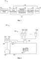
- FIG. 1 is a schematic representation of airflow progression 10 through an air conditioning system 12 of an aircraft. It is understood that the air conditioning system 12 is utilized for exemplary purposes and the embodiments disclosed herein may be applied to other systems other than an air conditioning system 12 of an aircraft.
- the airflow progression 10 is a representation of bleed air 14 as it passes from a compressor stage 16, to an air conditioning system 12 (which includes a heat exchanger 18, moisture extraction component 20, and air cycle machine 22), and onto a cabin 24.
- FIG. 1 is a simplified schematic representation of the system, highlighting locations of one or more flow path components in the airflow progression 10, which can include ductwork and other components within the airflow progression 10. All elements upstream of the heat exchanger 18 and downstream of the moisture extraction component 20 are not depicted.
- the moisture extraction component 20 may be a part of at least one of the compressor stage 16, the heat exchanger 18, the air cycle machine 22, and the cabin 24.
- a recirculation path 26 can extract air from the cabin 24 to use in combination with the bleed air 14 or in place of bleed air 14, for example, when the bleed air 14 is unavailable or insufficient.
- the air conditioning system 12 can be a sub-system of an aircraft engine that conditions bleed air 14 so that bleed air 14 can be re-used to perform an additional function within the aircraft.
- the bleed air 14 is taken from a compressor stage 16 of the aircraft engine. In other non-limiting embodiment, the bleed air 14 can be compressed air taken from an ambient environment.
- the compressor stage 16 can be an intermediate or high pressure stage within the aircraft engine.
- the heat exchanger 18 can be a condenser for condensing moisture from air into droplets.
- the moisture extraction component 20 can be an elongated tube of solid material with hydrophobic and/or hydrophilic surfaces for extracting moisture from air.
- the air cycle machine 22 is a component of the air conditioning system 12 for controlling the temperature and pressure of air exiting from the air cycle machine 22 and into cabin 24.
- the cabin 24 is a compartment of the aircraft for housing passengers and/or equipment.
- the compressor stage 16 can be fluidly connected to the heat exchanger 18 via fluid lines or conduits in the aircraft.
- the heat exchanger 18 can be fluidly connected to the moisture extraction component 20.
- the moisture extraction component 20 is fluidly connected to the air cycle machine 22, and the air cycle machine 22 is fluidly connected to the cabin 24.
- bleed air 14 is drawn from the compressor stage 16 and into the heat exchanger 18 of the air conditioning system 12.
- the heat exchanger 18 can cool and condense moisture in the bleed air 14 and/or from the recirculation path 26 from vapor into moisture droplets.
- the heat exchanger 18 can increase or decrease the temperature of air received at the heat exchanger 18.
- the air with the condensed moisture droplets can then be transported toward the air cycle machine 22.
- the air cycle machine 22 further conditions the air by altering the temperature and the pressure of the air to a level appropriate for the passengers in the cabin 24.
- a more detailed example of an aircraft air conditioning system and/or an environment control system can be found in United States Pat. No. 8,347,647B2 .
- FIG. 2 depicts an example of an additive manufacturing system 100 configured to perform an additive manufacturing process to form a flow path component 102, such as a heat exchanger 18, ducting, or other component of the air conditioning system 12 of FIG. 1 .
- the additive manufacturing system 100 is depicted schematically and can support any type of additive manufacturing processes known in the art.
- the additive manufacturing system 100 can be configured to support stereo-lithography using photo-polymerization or a fused deposition modelling process using extrusion-type printing to melt raw materials and form a plurality of layers.
- Other examples can include selective laser sintering, thermoforming, and known additive manufacturing processes.
- an application apparatus 104 can control the formation of a plurality of layers of the flow path component 102 within a manufacturing chamber 105.
- the application apparatus 104 can be selected corresponding to the type of additive manufacturing process employed.
- the application apparatus 104 may include a light emitting device or a laser and lens system for stereo-lithography or can include an extrusion head and nozzles for fused deposition modelling.
- a plurality of additive manufacturing materials 106 can be selectively formed into the flow path component 102 using the application apparatus 104 and other supporting subsystems, such as temperature and position controls.
- the additive manufacturing materials 106 can include a plurality of materials 106A, 106B, ..., 106N used at different manufacturing stages.
- a base material can be used to form a primary structure of the flow path component 102 as part of a 3-D printing process, for instance, of a non-metallic composite material.
- Other additive manufacturing materials 106 can include surface coatings, adhesive materials, antimicrobial nanoparticles, and other such materials.
- the additive manufacturing materials 106 can include any combination of liquid photopolymer, thermoplastic feedstock, powder, paste, and/or other known material types.
- the flow path component 102 may have a tacky surface to enable deposition and partial embedding of antimicrobial nanoparticles to surfaces of the flow path component 102 prior to a final curing stage. If the resulting flow surfaces of the flow path component 102 are not sufficiently tacky to support direct embedding of the antimicrobial nanoparticles to surfaces of the flow path component 102, an adhesive material can be applied to support embedding the antimicrobial nanoparticles in one or more flow surfaces of the flow path component 102. Examples of adhesive materials can include polyurethane, epoxy sealant binder, acrylic, photo-cured resin, and other such materials known in the art.
- a blower 108 can be operably coupled to the manufacturing chamber 105 to create an air vortex, such that release of the antimicrobial nanoparticles from the additive manufacturing materials 106 can be dust-blown onto surfaces of the flow path component 102 prior to final curing of the flow path component 102 by a curing device 110.
- the dust-blowing process is free of binders or solvents as opposed to typical spray coating applications. The dust-blowing process can result in coating over 95% of unmasked surfaces with the antimicrobial nanoparticles, while exposing surface area of the antimicrobial nanoparticles on flow surfaces of the flow path component 102.
- the curing device 110 can be a heating element operable to thermally cure the flow path component 102.
- the curing device 110 can be a light source, such as an ultraviolet light source, operable to perform photo-assist curing of the antimicrobial nanoparticles.
- the flow path component 102 may have a tacky or sticky surface that traps the antimicrobial nanoparticles when dust blown using the blower 108 within the manufacturing chamber 105. Depositing the antimicrobial nanoparticles prior to final curing results in embedding the antimicrobial nanoparticles at or substantially near the surface of the flow path component 102, such that the antimicrobial nanoparticles are at least partially exposed external to the surface.
- the antimicrobial nanoparticles can be, for example, silver and/or silver oxide nanoparticles operable to disrupt cell functions of bacteria.
- the dust-blowing process followed by a final curing results in forming a nanoscale texturing of the antimicrobial nanoparticles on the flow path component 102, where the texturing also kills or otherwise reduces bacterial adhesion.
- a controller 200 can interface with and control multiple elements of the additive manufacturing system 100, such as positions, flow rates, pressures, temperatures, and the like. Process steps, such as deposition and/or curing, can occur within the manufacturing chamber 105 or may be distributed between multiple instances of the manufacturing chamber 105. As an example, the controller 200 can control a deposition recipe and/or provide deposition/light control of the additive manufacturing materials 106 through the application apparatus 104, control airflow out of the blower 108, and control the curing device 110. In an embodiment, the controller 200 includes a memory system 202 to store instructions that are executed by a processing system 204 of the controller 200.
- the executable instructions may be stored or organized in any manner and at any level of abstraction, such as in connection with a controlling and/or monitoring operation of the additive manufacturing system 100.
- the processing system 204 can include one or more processors that can be any type of central processing unit (CPU), including a microprocessor, a digital signal processor (DSP), a microcontroller, an application specific integrated circuit (ASIC), a field programmable gate array (FPGA), or the like.
- the memory system 202 may include random access memory (RAM), read only memory (ROM), or other electronic, optical, magnetic, or any other computer readable medium onto which is stored data and control algorithms in a non-transitory form.
- FIG. 3 is a partial cross-sectional view of the flow path component 102 of FIG. 2 , according to an embodiment of the present disclosure.
- the example of FIG. 3 depicts a simple tube-like structure for purposes of explanation, it will be understood that the flow path component 102 can include complex features, such as a plurality of flow channels when embodied as the heat exchanger 18 of FIG. 1 .
- the flow path component 102 can include a flow path component body 302, an inlet 304, an outlet 306, an outer surface 308, an inner surface 310, and a main flow channel 312.
- the inner surface 310 of the flow path component 102 defines the main flow channel 312, which fluidly connects the inlet 304 to the outlet 306.
- a plurality of antimicrobial nanoparticles 314 are embedded in the inner surface 310 of the flow path component body 302 by the additive manufacturing system 100 of FIG. 2 .
- the flow path component body 302 is composed of a non-metallic material, and the antimicrobial nanoparticles 314 can include one or more of: silver and silver oxide nanoparticles.
- a coating can be applied to form a hydrophobic surface on the inner surface 310 prior to embedding the antimicrobial nanoparticles 314 in the inner surface 310 of the flow path component body 302, where the inner surface is an example of a flow surface 315.
- the hydrophobic surface can be composed of a hydrophobic compound configured to repel moisture away from the inner surface 310 of the flow path component body 302. As an air flow 316 propagates through the main low channel 312, bacteria contacting the antimicrobial nanoparticles 314 in the flow surface 315 can be killed due to the antimicrobial properties of the antimicrobial nanoparticles 314 and/or nanoscale texturing of the antimicrobial nanoparticles 314 on the flow surface 315.
- FIG. 4 depicts a cross section of a portion of the flow path component 102 according to an embodiment where the inner surface 310 and the outer surface 308 of the flow path component body 302 are both a flow surface 315 embedded with antimicrobial nanoparticles 314.
- the flow surface 315 on the flow path component body 302 can be a substantially planar surface embedded with antimicrobial nanoparticles 314 configured to kill bacteria entrained in air flow 316.
- Planar configurations may be portions of a larger apparatus, such as a plate-fin embodiment of the heat exchanger 18 of FIG. 1 .
- FIG. 6 depicts a simplified schematic view of a portion of nanoscale texturing 350 of the flow surface 315 of flow path component 102, according to an embodiment.
- the nanoscale texturing 350 includes pointed/sharp substantially conical structures 320 formed in polymer cure material that may perforate microbe cells. Externally exposed surface area of the antimicrobial nanoparticles 314 can also kill microorganisms in combination with the conical structures 320.
- the conical structures 320 is formed responsive to the dust-blown impact of the antimicrobial nanoparticles 314 on the flow surface 315 (e.g., where still tacky or an adhesive material is used) prior to final curing in combination with controlling parameters of the final curing process, for instance, by the controller 200 of FIG. 2 .
- FIG. 7 shows a method 400 of manufacturing a flow path component.
- an additive manufacturing process is performed using the additive manufacturing system 100 to form a flow path component 102 including a flow path component body 302 having a flow surface 315.
- a plurality of antimicrobial nanoparticles 314 is embedded in the flow surface 315 such that the antimicrobial nanoparticles 314 are at least partially exposed external to the flow surface 315.
- Embedding the antimicrobial nanoparticles 314 in the flow surface 315 of the flow path component body 302 includes applying the antimicrobial nanoparticles 314 to the flow surface 315 of the flow path component body 302 using the application apparatus 104 of the additive manufacturing system 100 and thermally or photo-assist curing the flow path component 102 using the curing device 110 after the antimicrobial nanoparticles 314 are applied from the additive manufacturing materials 106.
- Applying the antimicrobial nanoparticles 314 to the flow surface 315 of the flow path component body 302 includes distributing the antimicrobial nanoparticles 314 on the flow surface 315 using a dust-blowing process with the blower 108.
- An adhesive material can be applied on the flow surface 315 of the flow path component body 302 prior to circulating the antimicrobial nanoparticles 314 using the dust-blowing process, for example, to further enhance adhesion prior to final curing.
- Applying the antimicrobial nanoparticles 314 to the flow surface 315 of the flow path component body 302 can include applying a hydrophobic surface containing the antimicrobial nanoparticles 314 to the flow surface 315 of the flow path component body 302.
Landscapes
- Engineering & Computer Science (AREA)
- Materials Engineering (AREA)
- Chemical & Material Sciences (AREA)
- General Health & Medical Sciences (AREA)
- Pulmonology (AREA)
- Aviation & Aerospace Engineering (AREA)
- Physics & Mathematics (AREA)
- Health & Medical Sciences (AREA)
- Mechanical Engineering (AREA)
- Manufacturing & Machinery (AREA)
- Optics & Photonics (AREA)
- Life Sciences & Earth Sciences (AREA)
- Wood Science & Technology (AREA)
- General Engineering & Computer Science (AREA)
- Thermal Sciences (AREA)
- Application Of Or Painting With Fluid Materials (AREA)
- Powder Metallurgy (AREA)
Description
- The subject matter disclosed herein generally relates to the field of air conditioning components, and more particularly to a method and apparatus for manufacturing flow path components with antimicrobial surfaces for an air conditioning system for an aircraft.
- Air in an aircraft cabin can contain bacteria exerted from passengers and the environment. Current systems are designed to recycle air from the aircraft cabin; however, bacteria are reemitted into the cabin, whereby passengers can continue to be exposed. Traditional metallic heat exchangers and layup composite structures that makeup the ductwork of an aircraft air conditioning system cannot be readily modified to eliminate buildup and reentry of bacteria
EP 2 236 974 A2 describes a coated heat exchanger.CN 101 722 818 A describes an air conditioning system for an automobile.WO 2006/126783 A describes a method for manufacturing a heat exchanging coil fin unit. - A flow path component is provided and defined in claim 1.
- Preferred embodiments of the flow path component are identified in the dependent claims 2-5.
- An air conditioning system for an aircraft is defined in claim 6.
- A method of manufacturing a flow path component is provided and defined in claim 7.
- Preferred embodiments of the method of claim 7 are identified in the dependent claims 8-11.
- Technical effects of embodiments of the present disclosure include formation of antimicrobial surfaces on flow path components of an air conditioning system of an aircraft.
- The foregoing features and elements as well as the operation thereof will become more apparent in light of the following description and the accompanying drawings. It should be understood, however, that the following description and drawings are intended to be illustrative and explanatory in nature and non-limiting.
- The following descriptions should not be considered limiting in any way. With reference to the accompanying drawings, like elements are numbered alike:
-
FIG. 1 is a schematic representation of airflow progression through an air conditioning system, according to an embodiment of the present disclosure; -
FIG. 2 is a block diagram of an additive manufacturing system for forming a flow path component of the air conditioning system ofFIG. 1 , according to an embodiment of the present disclosure; -
FIG. 3 is a partial sectional view of a portion of a flow path component, according to an embodiment of the present disclosure; -
FIG. 4 is a partial sectional view of a portion of a flow path component, according to an embodiment of the present disclosure; -
FIG. 5 is a perspective view of a portion of a flow path component, according to an embodiment of the present disclosure; -
FIG. 6 is a schematic view of nanoscale texturing of a flow surface of a flow path component, according to an embodiment of the present disclosure; and -
FIG. 7 is a flow diagram of a method of manufacturing a flow path component with an antimicrobial surface. - A detailed description of one or more embodiments of the disclosed apparatus and method are presented herein by way of exemplification and not limitation with reference to the Figures.
-
FIG. 1 is a schematic representation ofairflow progression 10 through anair conditioning system 12 of an aircraft. It is understood that theair conditioning system 12 is utilized for exemplary purposes and the embodiments disclosed herein may be applied to other systems other than anair conditioning system 12 of an aircraft. Theairflow progression 10 is a representation of bleedair 14 as it passes from acompressor stage 16, to an air conditioning system 12 (which includes aheat exchanger 18,moisture extraction component 20, and air cycle machine 22), and onto acabin 24.FIG. 1 is a simplified schematic representation of the system, highlighting locations of one or more flow path components in theairflow progression 10, which can include ductwork and other components within theairflow progression 10. All elements upstream of theheat exchanger 18 and downstream of themoisture extraction component 20 are not depicted. It should be appreciated that, although particular systems inFIG. 1 are separately defined in the schematic block diagram, each or any of the systems may be otherwise combined or separated via hardware and/or software. For example, themoisture extraction component 20 may be a part of at least one of thecompressor stage 16, theheat exchanger 18, theair cycle machine 22, and thecabin 24. Arecirculation path 26 can extract air from thecabin 24 to use in combination with thebleed air 14 or in place ofbleed air 14, for example, when thebleed air 14 is unavailable or insufficient. - The
air conditioning system 12 can be a sub-system of an aircraft engine that conditions bleedair 14 so that bleedair 14 can be re-used to perform an additional function within the aircraft. Thebleed air 14 is taken from acompressor stage 16 of the aircraft engine. In other non-limiting embodiment, thebleed air 14 can be compressed air taken from an ambient environment. Thecompressor stage 16 can be an intermediate or high pressure stage within the aircraft engine. Theheat exchanger 18 can be a condenser for condensing moisture from air into droplets. Themoisture extraction component 20 can be an elongated tube of solid material with hydrophobic and/or hydrophilic surfaces for extracting moisture from air. Theair cycle machine 22 is a component of theair conditioning system 12 for controlling the temperature and pressure of air exiting from theair cycle machine 22 and intocabin 24. Thecabin 24 is a compartment of the aircraft for housing passengers and/or equipment. - The
compressor stage 16 can be fluidly connected to theheat exchanger 18 via fluid lines or conduits in the aircraft. Theheat exchanger 18 can be fluidly connected to themoisture extraction component 20. Themoisture extraction component 20 is fluidly connected to theair cycle machine 22, and theair cycle machine 22 is fluidly connected to thecabin 24. - During operation of the aircraft engine, bleed
air 14 is drawn from thecompressor stage 16 and into theheat exchanger 18 of theair conditioning system 12. Theheat exchanger 18 can cool and condense moisture in thebleed air 14 and/or from therecirculation path 26 from vapor into moisture droplets. In some non-limiting embodiments, theheat exchanger 18 can increase or decrease the temperature of air received at theheat exchanger 18. The air with the condensed moisture droplets can then be transported toward theair cycle machine 22. Theair cycle machine 22 further conditions the air by altering the temperature and the pressure of the air to a level appropriate for the passengers in thecabin 24. A more detailed example of an aircraft air conditioning system and/or an environment control system can be found inUnited States Pat. No. 8,347,647B2 -
FIG. 2 depicts an example of anadditive manufacturing system 100 configured to perform an additive manufacturing process to form aflow path component 102, such as aheat exchanger 18, ducting, or other component of theair conditioning system 12 ofFIG. 1 . Theadditive manufacturing system 100 is depicted schematically and can support any type of additive manufacturing processes known in the art. For example, theadditive manufacturing system 100 can be configured to support stereo-lithography using photo-polymerization or a fused deposition modelling process using extrusion-type printing to melt raw materials and form a plurality of layers. Other examples can include selective laser sintering, thermoforming, and known additive manufacturing processes. - In the example of
FIG. 2 , anapplication apparatus 104 can control the formation of a plurality of layers of theflow path component 102 within amanufacturing chamber 105. Theapplication apparatus 104 can be selected corresponding to the type of additive manufacturing process employed. For example, theapplication apparatus 104 may include a light emitting device or a laser and lens system for stereo-lithography or can include an extrusion head and nozzles for fused deposition modelling. A plurality of additive manufacturing materials 106 can be selectively formed into theflow path component 102 using theapplication apparatus 104 and other supporting subsystems, such as temperature and position controls. The additive manufacturing materials 106 can include a plurality ofmaterials flow path component 102 as part of a 3-D printing process, for instance, of a non-metallic composite material. Other additive manufacturing materials 106 can include surface coatings, adhesive materials, antimicrobial nanoparticles, and other such materials. The additive manufacturing materials 106 can include any combination of liquid photopolymer, thermoplastic feedstock, powder, paste, and/or other known material types. - Where ultraviolet curing or other curing methods are used as part of the additive manufacturing process, the
flow path component 102 may have a tacky surface to enable deposition and partial embedding of antimicrobial nanoparticles to surfaces of theflow path component 102 prior to a final curing stage. If the resulting flow surfaces of theflow path component 102 are not sufficiently tacky to support direct embedding of the antimicrobial nanoparticles to surfaces of theflow path component 102, an adhesive material can be applied to support embedding the antimicrobial nanoparticles in one or more flow surfaces of theflow path component 102. Examples of adhesive materials can include polyurethane, epoxy sealant binder, acrylic, photo-cured resin, and other such materials known in the art. - To support the application of antimicrobial nanoparticles to surfaces of the
flow path component 102 during the manufacturing process, ablower 108 can be operably coupled to themanufacturing chamber 105 to create an air vortex, such that release of the antimicrobial nanoparticles from the additive manufacturing materials 106 can be dust-blown onto surfaces of theflow path component 102 prior to final curing of theflow path component 102 by acuring device 110. The dust-blowing process is free of binders or solvents as opposed to typical spray coating applications. The dust-blowing process can result in coating over 95% of unmasked surfaces with the antimicrobial nanoparticles, while exposing surface area of the antimicrobial nanoparticles on flow surfaces of theflow path component 102. Thecuring device 110 can be a heating element operable to thermally cure theflow path component 102. Alternatively, thecuring device 110 can be a light source, such as an ultraviolet light source, operable to perform photo-assist curing of the antimicrobial nanoparticles. In embodiments, prior to final curing, theflow path component 102 may have a tacky or sticky surface that traps the antimicrobial nanoparticles when dust blown using theblower 108 within themanufacturing chamber 105. Depositing the antimicrobial nanoparticles prior to final curing results in embedding the antimicrobial nanoparticles at or substantially near the surface of theflow path component 102, such that the antimicrobial nanoparticles are at least partially exposed external to the surface. In some embodiments, the antimicrobial nanoparticles can be, for example, silver and/or silver oxide nanoparticles operable to disrupt cell functions of bacteria. In addition to the bactericidal properties of the antimicrobial nanoparticles, the dust-blowing process followed by a final curing results in forming a nanoscale texturing of the antimicrobial nanoparticles on theflow path component 102, where the texturing also kills or otherwise reduces bacterial adhesion. - A
controller 200 can interface with and control multiple elements of theadditive manufacturing system 100, such as positions, flow rates, pressures, temperatures, and the like. Process steps, such as deposition and/or curing, can occur within themanufacturing chamber 105 or may be distributed between multiple instances of themanufacturing chamber 105. As an example, thecontroller 200 can control a deposition recipe and/or provide deposition/light control of the additive manufacturing materials 106 through theapplication apparatus 104, control airflow out of theblower 108, and control thecuring device 110. In an embodiment, thecontroller 200 includes amemory system 202 to store instructions that are executed by aprocessing system 204 of thecontroller 200. The executable instructions may be stored or organized in any manner and at any level of abstraction, such as in connection with a controlling and/or monitoring operation of theadditive manufacturing system 100. Theprocessing system 204 can include one or more processors that can be any type of central processing unit (CPU), including a microprocessor, a digital signal processor (DSP), a microcontroller, an application specific integrated circuit (ASIC), a field programmable gate array (FPGA), or the like. Also, in embodiments, thememory system 202 may include random access memory (RAM), read only memory (ROM), or other electronic, optical, magnetic, or any other computer readable medium onto which is stored data and control algorithms in a non-transitory form. -
FIG. 3 is a partial cross-sectional view of theflow path component 102 ofFIG. 2 , according to an embodiment of the present disclosure. Although the example ofFIG. 3 depicts a simple tube-like structure for purposes of explanation, it will be understood that theflow path component 102 can include complex features, such as a plurality of flow channels when embodied as theheat exchanger 18 ofFIG. 1 . - The
flow path component 102 can include a flowpath component body 302, aninlet 304, anoutlet 306, anouter surface 308, aninner surface 310, and amain flow channel 312. Theinner surface 310 of theflow path component 102 defines themain flow channel 312, which fluidly connects theinlet 304 to theoutlet 306. A plurality ofantimicrobial nanoparticles 314 are embedded in theinner surface 310 of the flowpath component body 302 by theadditive manufacturing system 100 ofFIG. 2 . In some embodiments, the flowpath component body 302 is composed of a non-metallic material, and theantimicrobial nanoparticles 314 can include one or more of: silver and silver oxide nanoparticles. In some embodiments, a coating can be applied to form a hydrophobic surface on theinner surface 310 prior to embedding theantimicrobial nanoparticles 314 in theinner surface 310 of the flowpath component body 302, where the inner surface is an example of aflow surface 315. The hydrophobic surface can be composed of a hydrophobic compound configured to repel moisture away from theinner surface 310 of the flowpath component body 302. As anair flow 316 propagates through the mainlow channel 312, bacteria contacting theantimicrobial nanoparticles 314 in theflow surface 315 can be killed due to the antimicrobial properties of theantimicrobial nanoparticles 314 and/or nanoscale texturing of theantimicrobial nanoparticles 314 on theflow surface 315. -
FIG. 4 depicts a cross section of a portion of theflow path component 102 according to an embodiment where theinner surface 310 and theouter surface 308 of the flowpath component body 302 are both aflow surface 315 embedded withantimicrobial nanoparticles 314. Other variations are contemplated beyond annular or tubular structures. For example, as depicted inFIG. 5 , theflow surface 315 on the flowpath component body 302 can be a substantially planar surface embedded withantimicrobial nanoparticles 314 configured to kill bacteria entrained inair flow 316. Planar configurations may be portions of a larger apparatus, such as a plate-fin embodiment of theheat exchanger 18 ofFIG. 1 . -
FIG. 6 depicts a simplified schematic view of a portion ofnanoscale texturing 350 of theflow surface 315 offlow path component 102, according to an embodiment. Thenanoscale texturing 350 includes pointed/sharp substantiallyconical structures 320 formed in polymer cure material that may perforate microbe cells. Externally exposed surface area of theantimicrobial nanoparticles 314 can also kill microorganisms in combination with theconical structures 320. Theconical structures 320 is formed responsive to the dust-blown impact of theantimicrobial nanoparticles 314 on the flow surface 315 (e.g., where still tacky or an adhesive material is used) prior to final curing in combination with controlling parameters of the final curing process, for instance, by thecontroller 200 ofFIG. 2 . - Referring now to
FIG. 7 , with continued reference toFIGS. 1-6 .FIG. 7 shows amethod 400 of manufacturing a flow path component. Atblock 404, an additive manufacturing process is performed using theadditive manufacturing system 100 to form aflow path component 102 including a flowpath component body 302 having aflow surface 315. - At
block 406, a plurality ofantimicrobial nanoparticles 314 is embedded in theflow surface 315 such that theantimicrobial nanoparticles 314 are at least partially exposed external to theflow surface 315. Embedding theantimicrobial nanoparticles 314 in theflow surface 315 of the flowpath component body 302 includes applying theantimicrobial nanoparticles 314 to theflow surface 315 of the flowpath component body 302 using theapplication apparatus 104 of theadditive manufacturing system 100 and thermally or photo-assist curing theflow path component 102 using thecuring device 110 after theantimicrobial nanoparticles 314 are applied from the additive manufacturing materials 106. Applying theantimicrobial nanoparticles 314 to theflow surface 315 of the flowpath component body 302 includes distributing theantimicrobial nanoparticles 314 on theflow surface 315 using a dust-blowing process with theblower 108. An adhesive material can be applied on theflow surface 315 of the flowpath component body 302 prior to circulating theantimicrobial nanoparticles 314 using the dust-blowing process, for example, to further enhance adhesion prior to final curing. Applying theantimicrobial nanoparticles 314 to theflow surface 315 of the flowpath component body 302 can include applying a hydrophobic surface containing theantimicrobial nanoparticles 314 to theflow surface 315 of the flowpath component body 302. - While the above description has described the flow process of
FIG. 7 in a particular order, it should be appreciated that unless otherwise specifically required in the attached claims that the ordering of the steps may be varied. - The term "about" is intended to include the degree of error associated with measurement of the particular quantity based upon the equipment available at the time of filing the application. For example, "about" can include a range of ± 8% or 5%, or 2% of a given value.
- The terminology used herein is for the purpose of describing particular embodiments only and is not intended to be limiting of the present disclosure. As used herein, the singular forms "a", "an" and "the" are intended to include the plural forms as well, unless the context clearly indicates otherwise. It will be further understood that the terms "comprises" and/or "comprising," when used in this specification, specify the presence of stated features, integers, steps, operations, elements, and/or components, but do not preclude the presence or addition of one or more other features, integers, steps, operations, element components, and/or groups thereof.
- While the present disclosure has been described with reference to an exemplary embodiment or embodiments, it will be understood by those skilled in the art that various changes may be made for elements thereof without departing from the scope of the present disclosure. In addition, many modifications may be made to adapt a particular situation or material to the teachings of the present disclosure without departing from the essential scope thereof. Therefore, it is intended that the present disclosure not be limited to the particular embodiment disclosed as the best mode contemplated for carrying out this present disclosure, but that the present disclosure will include all embodiments falling within the scope of the claims.
Claims (11)
- A flow path component (102), comprising:a flow path component body (302) comprising a flow surface (310), the flow surface configured to be exposed to an air flow within a flow channel between an inlet and an outlet of the flow path component; anda plurality of antimicrobial nanoparticles (314) embedded in the flow surface (310) and at least partially exposed external to the flow surface (310) within the flow channel forming a nanoscale texturing on the flow surface, the nanoscale texturing comprising a plurality of pointed/sharp substantially conical structures (320) formed in polymer cure material, configured to perforate microbe cells between the antimicrobial nanoparticles embedded within the flow surface.
- The flow path component of claim 1, wherein the antimicrobial nanoparticles (314) comprise one or more of silver and silver oxide nanoparticles.
- The flow path component of claims 1 or 2, wherein the flow path component body (302) is composed of a non-metallic material.
- The flow path component of any preceding claim, wherein the flow surface (310) comprises a hydrophobic surface containing the antimicrobial nanoparticles (314).
- The flow path component of any preceding claim, wherein the antimicrobial nanoparticles (314) embedded in the flow surface (310) are bonded to the flow path component body (302) by an adhesive material.
- An air conditioning system for an aircraft, the air conditioning system comprising:an air cycle machine; anda heat exchanger operably coupled to the air cycle machine, the heat exchanger comprising at least one flow path component of any preceding claim.
- A method of manufacturing a flow path component, the method comprising:performing an additive manufacturing process to form the flow path component (102) comprising a flow path component body (302) with a flow surface (310), the flow surface configured to be exposed to an air flow within a flow channel between an inlet and an outlet of the flow path component; andembedding a plurality of antimicrobial nanoparticles (314) in the flow surface (310) such that the antimicrobial nanoparticles (314) are at least partially exposed external to the flow surface (310) within the flow channel and form a nanoscale texturing on the flow surface, the nanoscale texturing comprising a plurality of pointed/sharp substantially conical structures (320) formed in a polymer cure material configured to perforate microbe cells between the antimicrobial nanoparticles embedded within the flow surface, and wherein embedding the antimicrobial nanoparticles (314) in the flow surface of the flow path component body (302) comprises:applying an adhesive material on the flow surface (310) of the flow path component body (302) prior to circulating the antimicrobial nanoparticles (314) using a dust-blowing process;applying the antimicrobial nanoparticles (314) to the flow surface (310) of the flow path component body (302); andthermally or photo-assist curing the flow path component (102) after the antimicrobial nanoparticles (314) are applied, and wherein applying the antimicrobial nanoparticles (314) to the flow surface (310) of the flow path component body (302) further comprises distributing the antimicrobial nanoparticles (314) on the flow surface using the dust-blowing process.
- The method of claim 7, wherein applying the antimicrobial nanoparticles (314) to the flow surface (310) of the flow path component body (302) further comprises applying a hydrophobic surface containing the antimicrobial nanoparticles (314) to the flow surface of the flow path component body (302).
- The method of any of claims 7 to 8, wherein the flow path component body (302) is composed of a non-metallic material, the antimicrobial nanoparticles (314) comprise one or more of silver and silver oxide nanoparticles.
- The method of any of claims 7 to 9, wherein the additive manufacturing process comprises stereo lithography.
- The method of any of claims 7 to 9, wherein the additive manufacturing process comprises fused deposition modelling.
Applications Claiming Priority (1)
| Application Number | Priority Date | Filing Date | Title |
|---|---|---|---|
| US16/026,205 US11453197B2 (en) | 2018-07-03 | 2018-07-03 | Antimicrobial surfaces for flow path components |
Publications (2)
| Publication Number | Publication Date |
|---|---|
| EP3590838A1 EP3590838A1 (en) | 2020-01-08 |
| EP3590838B1 true EP3590838B1 (en) | 2025-03-26 |
Family
ID=67145598
Family Applications (1)
| Application Number | Title | Priority Date | Filing Date |
|---|---|---|---|
| EP19183902.6A Active EP3590838B1 (en) | 2018-07-03 | 2019-07-02 | Antimicrobial surfaces for flow path components |
Country Status (2)
| Country | Link |
|---|---|
| US (1) | US11453197B2 (en) |
| EP (1) | EP3590838B1 (en) |
Families Citing this family (2)
| Publication number | Priority date | Publication date | Assignee | Title |
|---|---|---|---|---|
| US20250033796A1 (en) * | 2023-07-24 | 2025-01-30 | Hamilton Sundstrand Corporation | Metal plating retention on additively manufacture plastic parts for an aircraft |
| US12384515B2 (en) | 2023-09-08 | 2025-08-12 | Hamilton Sundstrand Corporation | Airfoil formed of thermally adaptive materials and a thermoelectric junction |
Family Cites Families (14)
| Publication number | Priority date | Publication date | Assignee | Title |
|---|---|---|---|---|
| US20050191355A1 (en) * | 1999-05-27 | 2005-09-01 | Foss Manufacturing Co., Inc. | Anti-microbial and antifungal fluid conduits and methods of manufacture thereof |
| KR100656169B1 (en) * | 2002-12-23 | 2006-12-12 | 삼성전자주식회사 | Method to give antimicrobial property to the surface of object using nano sized metal particles |
| US8347647B2 (en) | 2004-09-22 | 2013-01-08 | Hamilton Sundstrand Corporation | Air cycle machine for an aircraft environmental control system |
| US20060141015A1 (en) | 2004-12-07 | 2006-06-29 | Centre Des Technologies Textiles | Antimicrobial material |
| JP2008542675A (en) * | 2005-05-24 | 2008-11-27 | ナノポリ カンパニー リミテッド | Coil fin material for heat exchange having sterilization function, and method and apparatus for manufacturing housing unit |
| US8852689B2 (en) * | 2007-05-29 | 2014-10-07 | Innova Dynamics, Inc. | Surfaces having particles and related methods |
| US10188103B2 (en) * | 2008-09-15 | 2019-01-29 | The Boeing Company | Antimicrobial coating fabrication method and structure |
| CN101722818A (en) * | 2008-10-20 | 2010-06-09 | 法雷奥企业管理(北京)有限公司上海分公司 | Air conditioning system of automobile |
| DE102009013054A1 (en) | 2009-03-16 | 2010-09-23 | Behr Gmbh & Co. Kg | heat exchangers |
| MX2015006002A (en) * | 2012-11-14 | 2016-02-05 | Orthopaedic Innovation Ct Inc | Antimicrobial articles produced by additive manufacturing. |
| US9818275B2 (en) | 2013-07-27 | 2017-11-14 | USS Technologies, LLC | Mobile apparatus for neutralizing anti-theft devices |
| EP3122393B1 (en) * | 2014-03-25 | 2020-04-22 | Orthopaedic Innovation Centre Inc. | Selective laser sintering process (sls) for producing antibiotic-eluting medical implants |
| US10371452B2 (en) * | 2016-10-11 | 2019-08-06 | Hamilton Sundstrand Corporation | Heat exchanger with support structure |
| US20190010335A1 (en) * | 2017-07-05 | 2019-01-10 | Saudi Arabian Oil Company | Hydrophobic coating for corrosion protection and method of fabrication |
-
2018
- 2018-07-03 US US16/026,205 patent/US11453197B2/en active Active
-
2019
- 2019-07-02 EP EP19183902.6A patent/EP3590838B1/en active Active
Also Published As
| Publication number | Publication date |
|---|---|
| US11453197B2 (en) | 2022-09-27 |
| US20200009826A1 (en) | 2020-01-09 |
| EP3590838A1 (en) | 2020-01-08 |
Similar Documents
| Publication | Publication Date | Title |
|---|---|---|
| EP3590838A1 (en) | Antimicrobial surfaces for flow path components | |
| JP6787967B2 (en) | Medical components with microstructure for humidification and condensate management | |
| US11110483B2 (en) | Liquid material dispensing system having a sleeve heater | |
| CN107596529A (en) | With for humidifying the medical components with the micro-structural of condensate management | |
| US20210353502A1 (en) | Systems and methods for high humidity curing within tablet coating system | |
| US10508864B2 (en) | Evaporative cooling in additive manufactured heat exchangers | |
| JP7331188B2 (en) | FLEXIBLE CONDUCTIVE ELEMENT AND FORMING METHOD THEREOF | |
| AR048553A1 (en) | MULTI-PATH DUCT AND RELATED MANUFACTURING PROCESS | |
| CN109501549B (en) | Vascular structures and methods for thermal management | |
| EP2508810A1 (en) | Ventilator module | |
| WO2021032420A1 (en) | Print head for an additive manufacturing system, and additive manufacturing system | |
| EP2168432A1 (en) | Antimicrobial coating fabrication method and structure | |
| CN109115396A (en) | Pipeline detecting system | |
| US20180236846A1 (en) | System and method for minimizing air leak in an hvac unit | |
| US11952696B2 (en) | Combination washing and drying apparatuses including cooled water condensers | |
| CN209521693U (en) | rail vehicle | |
| RU2646011C2 (en) | Method, system and device for liquid draining | |
| US20150338109A1 (en) | Auxiliary heating assembly for use with residential air handlers | |
| EP3208084A3 (en) | Hierarchical laminates fabricated from micro-scale, digitally patterned films | |
| JPH11115033A (en) | Device for preventing foreign matter from condensing/ sticking at lip outlet of flat die for extrusion molding | |
| DE102016217149B4 (en) | Method for operating a lighting device, lighting device for a motor vehicle and motor vehicle | |
| WO2022235782A8 (en) | Air conditioning system and control method | |
| CN105444386B (en) | The production method of outlet air adjustable plate, air conditioner indoor unit and outlet air adjustable plate | |
| US20060021934A1 (en) | Method and system for fabricating filter structure | |
| US20200003479A1 (en) | Hydrophobic surfaces for heat exchangers via atomic layer deposition |
Legal Events
| Date | Code | Title | Description |
|---|---|---|---|
| PUAI | Public reference made under article 153(3) epc to a published international application that has entered the european phase |
Free format text: ORIGINAL CODE: 0009012 |
|
| STAA | Information on the status of an ep patent application or granted ep patent |
Free format text: STATUS: THE APPLICATION HAS BEEN PUBLISHED |
|
| AK | Designated contracting states |
Kind code of ref document: A1 Designated state(s): AL AT BE BG CH CY CZ DE DK EE ES FI FR GB GR HR HU IE IS IT LI LT LU LV MC MK MT NL NO PL PT RO RS SE SI SK SM TR |
|
| AX | Request for extension of the european patent |
Extension state: BA ME |
|
| STAA | Information on the status of an ep patent application or granted ep patent |
Free format text: STATUS: REQUEST FOR EXAMINATION WAS MADE |
|
| 17P | Request for examination filed |
Effective date: 20200708 |
|
| RBV | Designated contracting states (corrected) |
Designated state(s): AL AT BE BG CH CY CZ DE DK EE ES FI FR GB GR HR HU IE IS IT LI LT LU LV MC MK MT NL NO PL PT RO RS SE SI SK SM TR |
|
| STAA | Information on the status of an ep patent application or granted ep patent |
Free format text: STATUS: EXAMINATION IS IN PROGRESS |
|
| 17Q | First examination report despatched |
Effective date: 20210622 |
|
| GRAP | Despatch of communication of intention to grant a patent |
Free format text: ORIGINAL CODE: EPIDOSNIGR1 |
|
| STAA | Information on the status of an ep patent application or granted ep patent |
Free format text: STATUS: GRANT OF PATENT IS INTENDED |
|
| INTG | Intention to grant announced |
Effective date: 20241023 |
|
| GRAS | Grant fee paid |
Free format text: ORIGINAL CODE: EPIDOSNIGR3 |
|
| GRAA | (expected) grant |
Free format text: ORIGINAL CODE: 0009210 |
|
| STAA | Information on the status of an ep patent application or granted ep patent |
Free format text: STATUS: THE PATENT HAS BEEN GRANTED |
|
| AK | Designated contracting states |
Kind code of ref document: B1 Designated state(s): AL AT BE BG CH CY CZ DE DK EE ES FI FR GB GR HR HU IE IS IT LI LT LU LV MC MK MT NL NO PL PT RO RS SE SI SK SM TR |
|
| REG | Reference to a national code |
Ref country code: GB Ref legal event code: FG4D |
|
| REG | Reference to a national code |
Ref country code: CH Ref legal event code: EP |
|
| REG | Reference to a national code |
Ref country code: DE Ref legal event code: R096 Ref document number: 602019067684 Country of ref document: DE |
|
| REG | Reference to a national code |
Ref country code: IE Ref legal event code: FG4D |
|
| PG25 | Lapsed in a contracting state [announced via postgrant information from national office to epo] |
Ref country code: RS Free format text: LAPSE BECAUSE OF FAILURE TO SUBMIT A TRANSLATION OF THE DESCRIPTION OR TO PAY THE FEE WITHIN THE PRESCRIBED TIME-LIMIT Effective date: 20250626 |
|
| PG25 | Lapsed in a contracting state [announced via postgrant information from national office to epo] |
Ref country code: FI Free format text: LAPSE BECAUSE OF FAILURE TO SUBMIT A TRANSLATION OF THE DESCRIPTION OR TO PAY THE FEE WITHIN THE PRESCRIBED TIME-LIMIT Effective date: 20250326 |
|
| PGFP | Annual fee paid to national office [announced via postgrant information from national office to epo] |
Ref country code: GB Payment date: 20250619 Year of fee payment: 7 |
|
| REG | Reference to a national code |
Ref country code: LT Ref legal event code: MG9D |
|
| PG25 | Lapsed in a contracting state [announced via postgrant information from national office to epo] |
Ref country code: NO Free format text: LAPSE BECAUSE OF FAILURE TO SUBMIT A TRANSLATION OF THE DESCRIPTION OR TO PAY THE FEE WITHIN THE PRESCRIBED TIME-LIMIT Effective date: 20250626 |
|
| PG25 | Lapsed in a contracting state [announced via postgrant information from national office to epo] |
Ref country code: HR Free format text: LAPSE BECAUSE OF FAILURE TO SUBMIT A TRANSLATION OF THE DESCRIPTION OR TO PAY THE FEE WITHIN THE PRESCRIBED TIME-LIMIT Effective date: 20250326 |
|
| PG25 | Lapsed in a contracting state [announced via postgrant information from national office to epo] |
Ref country code: LV Free format text: LAPSE BECAUSE OF FAILURE TO SUBMIT A TRANSLATION OF THE DESCRIPTION OR TO PAY THE FEE WITHIN THE PRESCRIBED TIME-LIMIT Effective date: 20250326 |
|
| PGFP | Annual fee paid to national office [announced via postgrant information from national office to epo] |
Ref country code: FR Payment date: 20250619 Year of fee payment: 7 |
|
| PG25 | Lapsed in a contracting state [announced via postgrant information from national office to epo] |
Ref country code: GR Free format text: LAPSE BECAUSE OF FAILURE TO SUBMIT A TRANSLATION OF THE DESCRIPTION OR TO PAY THE FEE WITHIN THE PRESCRIBED TIME-LIMIT Effective date: 20250627 Ref country code: BG Free format text: LAPSE BECAUSE OF FAILURE TO SUBMIT A TRANSLATION OF THE DESCRIPTION OR TO PAY THE FEE WITHIN THE PRESCRIBED TIME-LIMIT Effective date: 20250326 |
|
| REG | Reference to a national code |
Ref country code: NL Ref legal event code: MP Effective date: 20250326 |
|
| PG25 | Lapsed in a contracting state [announced via postgrant information from national office to epo] |
Ref country code: NL Free format text: LAPSE BECAUSE OF FAILURE TO SUBMIT A TRANSLATION OF THE DESCRIPTION OR TO PAY THE FEE WITHIN THE PRESCRIBED TIME-LIMIT Effective date: 20250326 |
|
| PG25 | Lapsed in a contracting state [announced via postgrant information from national office to epo] |
Ref country code: SE Free format text: LAPSE BECAUSE OF FAILURE TO SUBMIT A TRANSLATION OF THE DESCRIPTION OR TO PAY THE FEE WITHIN THE PRESCRIBED TIME-LIMIT Effective date: 20250326 |
|
| REG | Reference to a national code |
Ref country code: AT Ref legal event code: MK05 Ref document number: 1778846 Country of ref document: AT Kind code of ref document: T Effective date: 20250326 |
|
| PG25 | Lapsed in a contracting state [announced via postgrant information from national office to epo] |
Ref country code: SM Free format text: LAPSE BECAUSE OF FAILURE TO SUBMIT A TRANSLATION OF THE DESCRIPTION OR TO PAY THE FEE WITHIN THE PRESCRIBED TIME-LIMIT Effective date: 20250326 |
|
| PG25 | Lapsed in a contracting state [announced via postgrant information from national office to epo] |
Ref country code: PT Free format text: LAPSE BECAUSE OF FAILURE TO SUBMIT A TRANSLATION OF THE DESCRIPTION OR TO PAY THE FEE WITHIN THE PRESCRIBED TIME-LIMIT Effective date: 20250728 Ref country code: ES Free format text: LAPSE BECAUSE OF FAILURE TO SUBMIT A TRANSLATION OF THE DESCRIPTION OR TO PAY THE FEE WITHIN THE PRESCRIBED TIME-LIMIT Effective date: 20250326 |
|
| PGFP | Annual fee paid to national office [announced via postgrant information from national office to epo] |
Ref country code: DE Payment date: 20250620 Year of fee payment: 7 |
|
| PG25 | Lapsed in a contracting state [announced via postgrant information from national office to epo] |
Ref country code: PL Free format text: LAPSE BECAUSE OF FAILURE TO SUBMIT A TRANSLATION OF THE DESCRIPTION OR TO PAY THE FEE WITHIN THE PRESCRIBED TIME-LIMIT Effective date: 20250326 Ref country code: IT Free format text: LAPSE BECAUSE OF FAILURE TO SUBMIT A TRANSLATION OF THE DESCRIPTION OR TO PAY THE FEE WITHIN THE PRESCRIBED TIME-LIMIT Effective date: 20250326 |
|
| PG25 | Lapsed in a contracting state [announced via postgrant information from national office to epo] |
Ref country code: AT Free format text: LAPSE BECAUSE OF FAILURE TO SUBMIT A TRANSLATION OF THE DESCRIPTION OR TO PAY THE FEE WITHIN THE PRESCRIBED TIME-LIMIT Effective date: 20250326 |
|
| PG25 | Lapsed in a contracting state [announced via postgrant information from national office to epo] |
Ref country code: EE Free format text: LAPSE BECAUSE OF FAILURE TO SUBMIT A TRANSLATION OF THE DESCRIPTION OR TO PAY THE FEE WITHIN THE PRESCRIBED TIME-LIMIT Effective date: 20250326 |
|
| PG25 | Lapsed in a contracting state [announced via postgrant information from national office to epo] |
Ref country code: RO Free format text: LAPSE BECAUSE OF FAILURE TO SUBMIT A TRANSLATION OF THE DESCRIPTION OR TO PAY THE FEE WITHIN THE PRESCRIBED TIME-LIMIT Effective date: 20250326 |
|
| PG25 | Lapsed in a contracting state [announced via postgrant information from national office to epo] |
Ref country code: SK Free format text: LAPSE BECAUSE OF FAILURE TO SUBMIT A TRANSLATION OF THE DESCRIPTION OR TO PAY THE FEE WITHIN THE PRESCRIBED TIME-LIMIT Effective date: 20250326 |
|
| PG25 | Lapsed in a contracting state [announced via postgrant information from national office to epo] |
Ref country code: IS Free format text: LAPSE BECAUSE OF FAILURE TO SUBMIT A TRANSLATION OF THE DESCRIPTION OR TO PAY THE FEE WITHIN THE PRESCRIBED TIME-LIMIT Effective date: 20250726 |
|
| REG | Reference to a national code |
Ref country code: DE Ref legal event code: R097 Ref document number: 602019067684 Country of ref document: DE |
|
| PG25 | Lapsed in a contracting state [announced via postgrant information from national office to epo] |
Ref country code: DK Free format text: LAPSE BECAUSE OF FAILURE TO SUBMIT A TRANSLATION OF THE DESCRIPTION OR TO PAY THE FEE WITHIN THE PRESCRIBED TIME-LIMIT Effective date: 20250326 |
|
| PG25 | Lapsed in a contracting state [announced via postgrant information from national office to epo] |
Ref country code: CZ Free format text: LAPSE BECAUSE OF FAILURE TO SUBMIT A TRANSLATION OF THE DESCRIPTION OR TO PAY THE FEE WITHIN THE PRESCRIBED TIME-LIMIT Effective date: 20250326 |
|
| PLBE | No opposition filed within time limit |
Free format text: ORIGINAL CODE: 0009261 |
|
| STAA | Information on the status of an ep patent application or granted ep patent |
Free format text: STATUS: NO OPPOSITION FILED WITHIN TIME LIMIT |
|
| REG | Reference to a national code |
Ref country code: CH Ref legal event code: L10 Free format text: ST27 STATUS EVENT CODE: U-0-0-L10-L00 (AS PROVIDED BY THE NATIONAL OFFICE) Effective date: 20260211 |
|
| REG | Reference to a national code |
Ref country code: CH Ref legal event code: H13 Free format text: ST27 STATUS EVENT CODE: U-0-0-H10-H13 (AS PROVIDED BY THE NATIONAL OFFICE) Effective date: 20260224 |
|
| 26N | No opposition filed |
Effective date: 20260105 |
|
| PG25 | Lapsed in a contracting state [announced via postgrant information from national office to epo] |
Ref country code: LU Free format text: LAPSE BECAUSE OF NON-PAYMENT OF DUE FEES Effective date: 20250702 |
|
| REG | Reference to a national code |
Ref country code: BE Ref legal event code: MM Effective date: 20250731 |
|
| PG25 | Lapsed in a contracting state [announced via postgrant information from national office to epo] |
Ref country code: BE Free format text: LAPSE BECAUSE OF NON-PAYMENT OF DUE FEES Effective date: 20250731 |
|
| PG25 | Lapsed in a contracting state [announced via postgrant information from national office to epo] |
Ref country code: CH Free format text: LAPSE BECAUSE OF NON-PAYMENT OF DUE FEES Effective date: 20250731 |