EP3590787A1 - Method and system for monitoring a point system of a railway network, and point system of a railway network - Google Patents
Method and system for monitoring a point system of a railway network, and point system of a railway network Download PDFInfo
- Publication number
- EP3590787A1 EP3590787A1 EP19184298.8A EP19184298A EP3590787A1 EP 3590787 A1 EP3590787 A1 EP 3590787A1 EP 19184298 A EP19184298 A EP 19184298A EP 3590787 A1 EP3590787 A1 EP 3590787A1
- Authority
- EP
- European Patent Office
- Prior art keywords
- point system
- maneuver
- point
- values
- signal
- Prior art date
- Legal status (The legal status is an assumption and is not a legal conclusion. Google has not performed a legal analysis and makes no representation as to the accuracy of the status listed.)
- Withdrawn
Links
- 238000000034 method Methods 0.000 title claims abstract description 38
- 238000012544 monitoring process Methods 0.000 title claims abstract description 13
- 230000015556 catabolic process Effects 0.000 claims description 16
- 238000006731 degradation reaction Methods 0.000 claims description 16
- 239000013598 vector Substances 0.000 claims description 13
- 230000007246 mechanism Effects 0.000 claims description 5
- 230000000694 effects Effects 0.000 claims description 3
- 238000010801 machine learning Methods 0.000 claims description 3
- 230000008569 process Effects 0.000 claims description 3
- 230000002776 aggregation Effects 0.000 claims description 2
- 238000004220 aggregation Methods 0.000 claims description 2
- 238000000513 principal component analysis Methods 0.000 claims 1
- 238000013139 quantization Methods 0.000 claims 1
- 230000003362 replicative effect Effects 0.000 claims 1
- 230000036541 health Effects 0.000 description 22
- 238000012423 maintenance Methods 0.000 description 11
- 230000006399 behavior Effects 0.000 description 6
- 238000001514 detection method Methods 0.000 description 5
- 238000012545 processing Methods 0.000 description 5
- 230000009471 action Effects 0.000 description 3
- 238000003745 diagnosis Methods 0.000 description 3
- 230000011218 segmentation Effects 0.000 description 3
- 238000010586 diagram Methods 0.000 description 2
- 238000010606 normalization Methods 0.000 description 2
- 238000004393 prognosis Methods 0.000 description 2
- 241000283070 Equus zebra Species 0.000 description 1
- 229910000831 Steel Inorganic materials 0.000 description 1
- 230000002159 abnormal effect Effects 0.000 description 1
- 230000005856 abnormality Effects 0.000 description 1
- 230000008859 change Effects 0.000 description 1
- 238000012790 confirmation Methods 0.000 description 1
- 230000001934 delay Effects 0.000 description 1
- 230000001419 dependent effect Effects 0.000 description 1
- 238000005265 energy consumption Methods 0.000 description 1
- 230000007613 environmental effect Effects 0.000 description 1
- 239000000284 extract Substances 0.000 description 1
- 238000000605 extraction Methods 0.000 description 1
- 230000006870 function Effects 0.000 description 1
- 230000014509 gene expression Effects 0.000 description 1
- 230000005182 global health Effects 0.000 description 1
- 238000007689 inspection Methods 0.000 description 1
- 238000009434 installation Methods 0.000 description 1
- 230000003137 locomotive effect Effects 0.000 description 1
- 238000004519 manufacturing process Methods 0.000 description 1
- 230000000737 periodic effect Effects 0.000 description 1
- 238000007781 pre-processing Methods 0.000 description 1
- 239000010959 steel Substances 0.000 description 1
- 238000011179 visual inspection Methods 0.000 description 1
Images


Classifications
-
- B—PERFORMING OPERATIONS; TRANSPORTING
- B61—RAILWAYS
- B61L—GUIDING RAILWAY TRAFFIC; ENSURING THE SAFETY OF RAILWAY TRAFFIC
- B61L27/00—Central railway traffic control systems; Trackside control; Communication systems specially adapted therefor
- B61L27/50—Trackside diagnosis or maintenance, e.g. software upgrades
- B61L27/53—Trackside diagnosis or maintenance, e.g. software upgrades for trackside elements or systems, e.g. trackside supervision of trackside control system conditions
-
- B—PERFORMING OPERATIONS; TRANSPORTING
- B61—RAILWAYS
- B61L—GUIDING RAILWAY TRAFFIC; ENSURING THE SAFETY OF RAILWAY TRAFFIC
- B61L25/00—Recording or indicating positions or identities of vehicles or trains or setting of track apparatus
- B61L25/06—Indicating or recording the setting of track apparatus, e.g. of points, of signals
-
- B—PERFORMING OPERATIONS; TRANSPORTING
- B61—RAILWAYS
- B61L—GUIDING RAILWAY TRAFFIC; ENSURING THE SAFETY OF RAILWAY TRAFFIC
- B61L23/00—Control, warning or like safety means along the route or between vehicles or trains
- B61L23/04—Control, warning or like safety means along the route or between vehicles or trains for monitoring the mechanical state of the route
-
- B—PERFORMING OPERATIONS; TRANSPORTING
- B61—RAILWAYS
- B61L—GUIDING RAILWAY TRAFFIC; ENSURING THE SAFETY OF RAILWAY TRAFFIC
- B61L5/00—Local operating mechanisms for points or track-mounted scotch-blocks; Visible or audible signals; Local operating mechanisms for visible or audible signals
- B61L5/10—Locking mechanisms for points; Means for indicating the setting of points
- B61L5/107—Locking mechanisms for points; Means for indicating the setting of points electrical control of points position
-
- B—PERFORMING OPERATIONS; TRANSPORTING
- B61—RAILWAYS
- B61L—GUIDING RAILWAY TRAFFIC; ENSURING THE SAFETY OF RAILWAY TRAFFIC
- B61L7/00—Remote control of local operating means for points, signals, or track-mounted scotch-blocks
- B61L7/06—Remote control of local operating means for points, signals, or track-mounted scotch-blocks using electrical transmission
- B61L7/08—Circuitry
Definitions
- the present invention relates to a method and a system for monitoring a point system of a railway network, and to a point system of a railway network
- a point system comprises a point machine, some moving appliances, two stock rails and two switch rails.
- Point machines also known as switch machines, are used to operate track switches, also known as turnouts, that enable routing of trains from one track to another and that comprise stock rails and switch rails.
- These point systems tend to be relatively heavy mechanical or hydraulic machines moving heavy steel appliances in sometimes extreme conditions. Failure of a point system can cause total blockage of a railway, since a safe route over a switch may not be established for a train due to the failure.
- Point systems are lubricated, adjusted, and otherwise maintained on a periodic basis, but given the often remote location of these systems, the maintainers may be unaware of the impact on the track layout of the number of operations, weather, and changing ground surface conditions, or of the maintenance operation itself.
- the method needs a monitor and a processor device so that the operator must be physically on the operating site and manually trigger the different tasks to perform the point system monitoring.
- Another problem of the method disclosed in the above indicated document is that the healthy reference is learnt from a single movement (the first movement), therefore, the natural variations of the waveforms are not included in this reference and there is a significant risk to confuse environmental change with real degradations, and thus to make false detection and diagnosis.
- the technical problem to solve is therefore how to perform a remote and automated detection of anomalies in a point system, a remote and automated identification of a degradation in the conditions of the point system and a remote and automated prognosis of the remaining time before failure of a turnout.
- An object of the present invention is therefore to provide a method for monitoring a point system of a railway network which allows to perform a remote and automated analysis of the conditions of the point system in order to foresee anomalies and plan maintenance interventions, which allows to make diagnosis of degradation conditions of the point system itself and to identify the time remaining before a next failure of the point system, thus overcoming the limitations of the prior art systems.
- the method of the present invention performs an anomaly detection, a degradation diagnosis and a prognosis of a remaining useful life of the point system itself by monitoring current and voltage signals supplied to the point system during its maneuvers, and by following their evolution in time.
- the method according to the present invention is based on the acquisition of current and voltage signals supplied to a point machine.
- the signals are firstly segmented according to different phases of a maneuver, then they are compressed into a set of features that are physically relevant for assessing the condition of the point system.
- the core of the method of the present invention relies on the processing done on the signals and on the way the degradations are recognized.
- the method of the present invention aims at assessing the conditions of a railway turnout remotely, automatically and in real-time, in order to provide the maintainers with useful and precise information regarding the actual operation of the corresponding point system.
- the method allows therefore the maintenance to properly plan actions on the various point systems, in particular only when necessary, to avoid service affecting failures.
- Figure 1 shows a block diagram of the steps of a method according to the present invention.
- a first step 2 several sensors per se known are placed in correspondence with respective point systems.
- the sensors are placed in a manner known per se in an interlocking equipment of an interlocking system, for example in the single pushing point electro-mechanical point machine with open-loop control configuration, or in the point system itself, for example in the single pushing point electro-mechanical point machine with closed-loop control configuration.
- a next step 4 for each point system, the sensors acquire current and voltage signals of a turnout during a maneuver. These signals are transferred, along with any relevant information disclosed here below, to a processing unit placed in a remote cabin along the railway track which segments, in a step 6, the signals of the maneuver according to different predetermined phases of movement, preferably unlocking of a locking system of the point machine (or unlocking of an external locking system associated with the point system), movement of the blades of the point system, closing of the locking system, locking of the locking system.
- Examples of relevant information transferred to the processing unit include:
- Figure 2 and figure 3 show two examples of a current signal segmented according to the different phases of movement, respectively for a single pushing point electro-mechanical point machine with open-loop control and for a single pushing point electro-mechanical point machine with closed-loop control.
- the stroke of a slider has always a predetermined width, for example 214 mm, hence whatever are the signal shape and the time span for a maneuver, the slider will cover a stroke of such width.
- the analysis has aimed to identify a correlation between parts of the slider stroke and movement of internal components.
- the expected result was a stroke division into segments associated to the movements of specific subset of components, as herein below disclosed.
- a first zone 100 corresponds to the moment when a locking system of a point machine is unlocked, before a maneuver starts.
- a second zone 102 corresponds to the movement of a first switch rail.
- a third zone 104 corresponds to the movement of both switch rails.
- a fourth zone 106 corresponds to the closing of the first switch in a final position while the second switch rail continues to move, and a fifth zone 108 corresponds to the locking of the point system.
- a maneuver starts at a predetermined point system.
- a second zone 202 there is a movement of internal components of a locking system of the point system to unlock the locking system itself.
- the locking system is unblocked and in a further zone 206 there is the rails movement.
- the locking system is blocked, in a further zone 210 the locking system is locked and in a final zone 212 the manoeuver is terminated.
- the segmentation is advantageously realized based on a known stroke of a slider of the point machine.
- the slider stroke is subdivided in segments based on identified movements of specific subset of the point system.
- the processing unit extracts, for each segment disclosed with reference to figures 2 and 3 , and for each current and voltage signal, relevant features such as the peak value of the signal, differentials, average, etc.
- the set of extracted values are different for different point systems. For example, for a first type point system known per se, the average and the standard deviation of the first three segments are extracted, whereas for a second type point system known per se, the duration and the slope of the first segment and the kurtosis on the second segment are extracted.
- the selection of features is based on the physical behavior of the point system itself, therefore, if the behavior is different between the first and the second type point system, the features also vary.
- the extracted features which represent statistical and physical characteristics of the point system, belong to different groups:
- the maneuver is represented by a vector of features which highlight the physical behavior of the point system.
- the vector comprises the features of both the current and voltage signal. This reduces significantly the data to be treated, and subsequently the volume of data to be communicated and processed at the following steps.
- the feature extraction represents the final step in a pre-processing phase.
- a vector representing the maneuver is determined, the vector comprising said extracted features, e.g. peak values, differential values, average values, mean values measured during each segment of the maneuver.
- the vector is compared with a library of vectors relative to degradation mechanisms, and the degradation mechanism is determined in function of the comparison.
- the processing unit compares the set of extracted features with a set of predetermined reference features or values which represent a "healthy” maneuver, thus producing a "health” index or indicator as disclosed herein below.
- the “health” index is a numerical value which indicates the level of degradation of the target equipment with respect to a failure threshold and varies monotonically with the condition of the equipment.
- the “health” index is an aggregation or selection of health indicators as herebelow disclosed, and is used to define an overall global “health” of the point system.
- the “health” index is used in prognostics for an estimation of an expected evolution in time and, thus, of an estimated time before an expected failure.
- the “health” index is calculated based on a comparison between the vector above disclosed and several references values. In particular, the health index is compared with a threshold value representative of the health index of N previous maneuvers, in order to determine whether the current maneuver is healthy or not.
- the expressions "health” or “healthy” refer to a maneuver which takes place at a point system which is in good operating conditions, which do not need maintenance, etc.
- the predetermined reference "healthy” values are values automatically learnt with a machine learning process from data relative to previous maneuvers.
- a priori predetermined maneuvers in particular forty maneuvers, are identified as "healthy”.
- a corresponding area in a feature-space, which corresponds to a healthy region, can be therefore determined.
- an area can be defined as "healthy”.
- the degree of health or abnormality of a new maneuver is therefore represented by the distance between the "healthy” area in the feature-space and the new maneuver itself.
- the "health” index is defined as the distance between an healthy maneuver and a current maneuver in the feature-space.
- predetermining will refer to a value(s) learnt each time thanks to a machine learning process known per se, based on the concepts above disclosed.
- a Gaussian normalization is done as here disclosed: a predetermined mean is subtracted from the original value of each feature taken from the signal and divided by a predetermined standard deviation.
- the predetermined mean is a value calculated as the mean of the set of reference "healthy” values (the baseline above indicated), and the predetermined deviation standard is one value of the set of reference "healthy” values (the baseline above disclosed).
- the result of such normalization is called “indicator”.
- the indicators of all the features, relating to both the current signal and the voltage signal are then combined, to give a single value called global "health” indicator.
- the global "health” indicator is the Mahalanobis distance calculated from the set of indicators.
- a failure threshold and a set of AND rules are then applied in a manner known per se to the value of the global "health” indicator to assess the state of the point system: healthy, abnormal or degraded.
- the global "health” indicator exceeds the failure threshold, this means that the point system is about to have a failure.
- AND rules include the following: if the time between the current maneuver and the previous one is less than a predetermined time, for example one minute, and the energy of the maneuver is above a threshold, then some maintenance is occurring
- the values of the indicators are concatenated into a vector called signature, said values representing the effect of a given degradation on the point system, which are an immediate, direct and easy to understand interpretation of the characteristics of the turnout.
- the "health" state is expressed in a user-friendly web interface which allows an immediate comprehension of the state of the point system together with a list of possible failure mechanisms.
- the interface helps the maintainers to understand the type of maintenance intervention necessary to restore the asset of the point system as well as the urgency of the action.
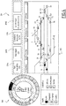
- Figure 4 shows an example of such interface.
- This interface offers an overview of a railway network being monitored, and is divided into three main areas, namely a global vision area 300, a field layout area 302 and an overall summary area 304.
- each point system is a square in these rings.
- the "health" of each point system is indicated by a color.
- the availability of the machines is indicated by various hues in the internal ring, where a dark zone indicates that there is a maintenance action being performed on the point system, a light zone indicates that the point system is offline because the sensors are not sending data and a medium colored zone indicates that the switch point system is online. It is possible to select any machine from the ring to see the corresponding reference index.
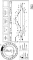
- the monitored point systems are presented in their real on-field configuration, colored by their "health" state to immediately identify which machines are in need of maintenance. If the machines are offline or under maintenance, this is reported as shown in Figure 5 .
- turnout 2 indicated by reference 500
- turnout 500 is undergoing maintenance. This can be seen from the dark frame in field layout area 302 and from the "zebra" section 502 in the global vision area 300.
- a first zone 304a indicates the availability of the monitored machines, in other words the percentage of machines which are online over the total.
- a second zone 304b is the global health of the machines, in other words the percentage of machines which are "healthy" over the total.
- a third zone 304c indicates the total number of maneuvers registered since the installation date.
- a fourth zone 304d is the date and time of the last maneuver monitored, to give an indication of how updated the page is.
- the method of the present invention has been able to detect faults which the maintainers had not noticed, as well as power supply interruptions, obstacles and rail deformation. Therefore, the detection capabilities of the method of the present invention have proven to be more effective than visual inspections.
- the present invention further comprises a monitoring system for monitoring a point system of a railway network which includes:
- Further subject of the present invention is a point system of a railway network including a plurality of sensors arranged to be connected to an elaboration unit arranged to carry out the method of the present invention.
Landscapes
- Engineering & Computer Science (AREA)
- Mechanical Engineering (AREA)
- Health & Medical Sciences (AREA)
- Biomedical Technology (AREA)
- General Health & Medical Sciences (AREA)
- Train Traffic Observation, Control, And Security (AREA)
- Electric Propulsion And Braking For Vehicles (AREA)
Abstract
- placing (2) several sensors in correspondence of said at least one point system;
- acquiring (4) from said sensors current and voltage signals of a point machine during a maneuver;
- segmenting (6) the signals of the maneuver according to different predetermined phases of movement;
- extracting (8) predetermined features from each segment;
- comparing (10) the extracted features with a set of predetermined values which represent a "healthy" maneuver, thus obtaining a global indicator representative of the conditions of the maneuver at the point system;
- comparing said global indicator with a failure threshold, and if it exceeds said failure threshold, detecting a failure in the point system.
Description
- The present invention relates to a method and a system for monitoring a point system of a railway network, and to a point system of a railway network
- A point system comprises a point machine, some moving appliances, two stock rails and two switch rails.
- Point machines, also known as switch machines, are used to operate track switches, also known as turnouts, that enable routing of trains from one track to another and that comprise stock rails and switch rails. These point systems tend to be relatively heavy mechanical or hydraulic machines moving heavy steel appliances in sometimes extreme conditions. Failure of a point system can cause total blockage of a railway, since a safe route over a switch may not be established for a train due to the failure.
- These major events can cause delays to freight and passenger trains, failure to meet schedules that often result in financial penalties, additional costs of train crews and locomotive operations, blockage of highway crossings and reputation loss to customers.
- Point systems are lubricated, adjusted, and otherwise maintained on a periodic basis, but given the often remote location of these systems, the maintainers may be unaware of the impact on the track layout of the number of operations, weather, and changing ground surface conditions, or of the maintenance operation itself.
- It is known to monitor the conditions of a point system, as shown for example in document
US 2015/0158511 , wherein a waveform of the operating characteristics is examined to identify or predict a problem with the operations of the point system. - One problem of the method disclosed in the above indicated document is that turnouts are generally inspected on a scheduled basis, therefore, failures which severely affect the railway traffic may happen in the time period between two inspections without possibility to foresee them.
- Also, the method needs a monitor and a processor device so that the operator must be physically on the operating site and manually trigger the different tasks to perform the point system monitoring.
- Another problem of the method disclosed in the above indicated document is that the healthy reference is learnt from a single movement (the first movement), therefore, the natural variations of the waveforms are not included in this reference and there is a significant risk to confuse environmental change with real degradations, and thus to make false detection and diagnosis.
- The technical problem to solve is therefore how to perform a remote and automated detection of anomalies in a point system, a remote and automated identification of a degradation in the conditions of the point system and a remote and automated prognosis of the remaining time before failure of a turnout.
- An object of the present invention is therefore to provide a method for monitoring a point system of a railway network which allows to perform a remote and automated analysis of the conditions of the point system in order to foresee anomalies and plan maintenance interventions, which allows to make diagnosis of degradation conditions of the point system itself and to identify the time remaining before a next failure of the point system, thus overcoming the limitations of the prior art systems.
- These and other objects are achieved by a method for monitoring a point system of a railway network having the characteristics defined in
claim 1. - Further subjects of the present invention are a system for monitoring a point system of a railway network, and a point system of a railway network as claimed.
- Particular embodiments of the invention are the subject of the dependent claims, whose content is to be understood as an integral or integrating part of the present description.
- Thanks to the fact that when a degradation appears in a point system its kinematic behavior is different and the energy consumption profile is affected, the method of the present invention performs an anomaly detection, a degradation diagnosis and a prognosis of a remaining useful life of the point system itself by monitoring current and voltage signals supplied to the point system during its maneuvers, and by following their evolution in time.
- Further characteristics and advantages of the present invention will become apparent from the following description, provided merely by way of a non-limiting example, with reference to the enclosed drawings, in which:
-
Figure 1 shows a schematic block diagram of the steps performed by a method according to the present invention; -
Figure 2 is an example of a signal segmented according to different phases of movement, for a single pushing point electro-mechanical point machine with open-loop control; -
Figure 3 is an example of a signal segmented according to different phases of movement, for a single pushing point electro-mechanical point machine with closed-loop control; -
Figure 4 shows an interface for expressing a reference index calculated according to a method of the present invention; and -
Figure 5 shows an alternative embodiment of the interface offigure 4 . - The method according to the present invention is based on the acquisition of current and voltage signals supplied to a point machine.
- The signals are firstly segmented according to different phases of a maneuver, then they are compressed into a set of features that are physically relevant for assessing the condition of the point system.
- The analysis is performed for each point system of a railway network and for each direction (Normal/Reverse) independently, this being precise and robust to variability.
- The core of the method of the present invention relies on the processing done on the signals and on the way the degradations are recognized.
- The method of the present invention aims at assessing the conditions of a railway turnout remotely, automatically and in real-time, in order to provide the maintainers with useful and precise information regarding the actual operation of the corresponding point system. The method allows therefore the maintenance to properly plan actions on the various point systems, in particular only when necessary, to avoid service affecting failures.
-
Figure 1 shows a block diagram of the steps of a method according to the present invention. - In a
first step 2, several sensors per se known are placed in correspondence with respective point systems. For example, the sensors are placed in a manner known per se in an interlocking equipment of an interlocking system, for example in the single pushing point electro-mechanical point machine with open-loop control configuration, or in the point system itself, for example in the single pushing point electro-mechanical point machine with closed-loop control configuration. - In a
next step 4, for each point system, the sensors acquire current and voltage signals of a turnout during a maneuver. These signals are transferred, along with any relevant information disclosed here below, to a processing unit placed in a remote cabin along the railway track which segments, in astep 6, the signals of the maneuver according to different predetermined phases of movement, preferably unlocking of a locking system of the point machine (or unlocking of an external locking system associated with the point system), movement of the blades of the point system, closing of the locking system, locking of the locking system. - Examples of relevant information transferred to the processing unit include:
- current supplied at the point system and used during the maneuver;
- voltage applied to the point system during the maneuver;
- direction of the maneuver;
- time taken to complete the maneuver;
- detection of the position of the point system at the end of the maneuver (confirmation that the maneuver has been completed successfully);
- point system actually doing the maneuver under analysis.
-
Figure 2 and figure 3 show two examples of a current signal segmented according to the different phases of movement, respectively for a single pushing point electro-mechanical point machine with open-loop control and for a single pushing point electro-mechanical point machine with closed-loop control. - All the steps of the method of the present invention are performed simultaneously on both the current and the voltage signal, and the features extracted from these signals herein below disclosed are combined for the final analysis, as below detailed.
- With regard to the
segmentation step 6, it is worth pointing out that the stroke of a slider has always a predetermined width, for example 214 mm, hence whatever are the signal shape and the time span for a maneuver, the slider will cover a stroke of such width. - Starting from this stroke and considering that the internal components of the point system do not move all at the same time, the analysis has aimed to identify a correlation between parts of the slider stroke and movement of internal components. At the end of the analysis, the expected result was a stroke division into segments associated to the movements of specific subset of components, as herein below disclosed.
- In
figure 2 , afirst zone 100 corresponds to the moment when a locking system of a point machine is unlocked, before a maneuver starts. Asecond zone 102 corresponds to the movement of a first switch rail. Athird zone 104 corresponds to the movement of both switch rails. Afourth zone 106 corresponds to the closing of the first switch in a final position while the second switch rail continues to move, and afifth zone 108 corresponds to the locking of the point system. - In
figure 3 , in a first zone 200 a maneuver starts at a predetermined point system. In asecond zone 202 there is a movement of internal components of a locking system of the point system to unlock the locking system itself. In afurther zone 204 the locking system is unblocked and in afurther zone 206 there is the rails movement. In asubsequent zone 208 the locking system is blocked, in afurther zone 210 the locking system is locked and in afinal zone 212 the manoeuver is terminated. - The segmentation is advantageously realized based on a known stroke of a slider of the point machine. The slider stroke is subdivided in segments based on identified movements of specific subset of the point system.
- Returning now to
figure 1 , atstep 8, the processing unit extracts, for each segment disclosed with reference tofigures 2 and 3 , and for each current and voltage signal, relevant features such as the peak value of the signal, differentials, average, etc. The set of extracted values are different for different point systems. For example, for a first type point system known per se, the average and the standard deviation of the first three segments are extracted, whereas for a second type point system known per se, the duration and the slope of the first segment and the kurtosis on the second segment are extracted. The selection of features is based on the physical behavior of the point system itself, therefore, if the behavior is different between the first and the second type point system, the features also vary. - The extracted features, which represent statistical and physical characteristics of the point system, belong to different groups:
- context features: necessary to contextualize the maneuver, for example if a maneuver is complete, if it is a maintenance maneuver, if the machine is being operated at a particular temperature, etc.;
- usage features: to contextualize the frequency of use of the point system;
- turnout "health" features: characteristics necessary to contextualize the global turnout behavior;
- point machine "health" features:
- a) global: characteristics of the signal that relate to the point machine ;
- b) segments: characteristics of the signal that relate to each segment (or phase of movement) of the point machine ;
- In the following of the description, reference will be made in general only to "extracted features".
- Through this
segmentation step 6, the maneuver is represented by a vector of features which highlight the physical behavior of the point system. The vector comprises the features of both the current and voltage signal. This reduces significantly the data to be treated, and subsequently the volume of data to be communicated and processed at the following steps. - The feature extraction represents the final step in a pre-processing phase.
- Advantageously, therefore, a vector representing the maneuver is determined, the vector comprising said extracted features, e.g. peak values, differential values, average values, mean values measured during each segment of the maneuver.
- Advantageously the vector is compared with a library of vectors relative to degradation mechanisms, and the degradation mechanism is determined in function of the comparison.
- At
step 10 the processing unit compares the set of extracted features with a set of predetermined reference features or values which represent a "healthy" maneuver, thus producing a "health" index or indicator as disclosed herein below. - The "health" index is a numerical value which indicates the level of degradation of the target equipment with respect to a failure threshold and varies monotonically with the condition of the equipment. The "health" index is an aggregation or selection of health indicators as herebelow disclosed, and is used to define an overall global "health" of the point system. The "health" index is used in prognostics for an estimation of an expected evolution in time and, thus, of an estimated time before an expected failure. The "health" index is calculated based on a comparison between the vector above disclosed and several references values. In particular, the health index is compared with a threshold value representative of the health index of N previous maneuvers, in order to determine whether the current maneuver is healthy or not.
- In the present description the expressions "health" or "healthy" refer to a maneuver which takes place at a point system which is in good operating conditions, which do not need maintenance, etc.
- To perform such comparison, for each segment, as indicated above, different features such as the mean of the signal, the maximum of the signal, the derivative of the signal, the slope of the curve, are extracted in a manner known per se. These values are then normalized with respect to a set of predetermined reference "healthy" values of features.
- The predetermined reference "healthy" values are values automatically learnt with a machine learning process from data relative to previous maneuvers. In particular, in order to detect a deviation from what is expected to be a healthy behavior, and therefore to detect an anomaly, a priori predetermined maneuvers, in particular forty maneuvers, are identified as "healthy". A corresponding area in a feature-space, which corresponds to a healthy region, can be therefore determined. In other words, in an n-dimensional space, where n is the number of features taken into consideration, an area can be defined as "healthy". These forty maneuvers, twenty per each direction of movement along the railway track, are referred to as "baseline", as they define a base value against which current new values have to be compared.
- The degree of health or abnormality of a new maneuver is therefore represented by the distance between the "healthy" area in the feature-space and the new maneuver itself. The "health" index is defined as the distance between an healthy maneuver and a current maneuver in the feature-space.
- In the following of the description, the term "predetermined" will refer to a value(s) learnt each time thanks to a machine learning process known per se, based on the concepts above disclosed.
- Preferably, a Gaussian normalization is done as here disclosed: a predetermined mean is subtracted from the original value of each feature taken from the signal and divided by a predetermined standard deviation. In particular, the predetermined mean is a value calculated as the mean of the set of reference "healthy" values (the baseline above indicated), and the predetermined deviation standard is one value of the set of reference "healthy" values (the baseline above disclosed).
- The result of such normalization is called "indicator". The indicators of all the features, relating to both the current signal and the voltage signal, are then combined, to give a single value called global "health" indicator. In particular, the global "health" indicator is the Mahalanobis distance calculated from the set of indicators. A failure threshold and a set of AND rules are then applied in a manner known per se to the value of the global "health" indicator to assess the state of the point system: healthy, abnormal or degraded. In particular, if the global "health" indicator exceeds the failure threshold, this means that the point system is about to have a failure.
- Examples of AND rules include the following: if the time between the current maneuver and the previous one is less than a predetermined time, for example one minute, and the energy of the maneuver is above a threshold, then some maintenance is occurring
- Several shape parameters of the acquired signals/the extracted features are therefore normalized with respect to learnt baselines and then combined (the Mahalanobis distance) to calculate the global "health" indicator which represents how similar the actual shape of the signals is to the shape of a set of "healthy" reference curves.
- At this point, at
step 12, the values of the indicators are concatenated into a vector called signature, said values representing the effect of a given degradation on the point system, which are an immediate, direct and easy to understand interpretation of the characteristics of the turnout. - The "health" state is expressed in a user-friendly web interface which allows an immediate comprehension of the state of the point system together with a list of possible failure mechanisms. The interface helps the maintainers to understand the type of maintenance intervention necessary to restore the asset of the point system as well as the urgency of the action.
-
Figure 4 shows an example of such interface. This interface offers an overview of a railway network being monitored, and is divided into three main areas, namely aglobal vision area 300, afield layout area 302 and anoverall summary area 304. - In the
global vision area 300 there are two types of information for all the point systems being monitored: reference information and availability information. This information is summarized by two rings, respectively an internal and an external ring, wherein each point system is a square in these rings. - The "health" of each point system is indicated by a color. The availability of the machines is indicated by various hues in the internal ring, where a dark zone indicates that there is a maintenance action being performed on the point system, a light zone indicates that the point system is offline because the sensors are not sending data and a medium colored zone indicates that the switch point system is online. It is possible to select any machine from the ring to see the corresponding reference index.
- In the
field layout area 302, the monitored point systems are presented in their real on-field configuration, colored by their "health" state to immediately identify which machines are in need of maintenance. If the machines are offline or under maintenance, this is reported as shown inFigure 5 . - In
figure 5 it is possible to see thatturnout 2, indicated byreference 500, is undergoing maintenance. This can be seen from the dark frame infield layout area 302 and from the "zebra"section 502 in theglobal vision area 300. - Returning now to
figure 4 , in theoverall summary area 304 it is possible to see an overview of the characteristics of the railway network being monitored. Afirst zone 304a indicates the availability of the monitored machines, in other words the percentage of machines which are online over the total. Asecond zone 304b is the global health of the machines, in other words the percentage of machines which are "healthy" over the total. Athird zone 304c indicates the total number of maneuvers registered since the installation date. Afourth zone 304d is the date and time of the last maneuver monitored, to give an indication of how updated the page is. - The method of the present invention has been able to detect faults which the maintainers had not noticed, as well as power supply interruptions, obstacles and rail deformation. Therefore, the detection capabilities of the method of the present invention have proven to be more effective than visual inspections.
- The present invention further comprises a monitoring system for monitoring a point system of a railway network which includes:
- a point system of a railway network as above disclosed;
- a plurality of sensors per se known placed in correspondence with said point system; and
- an elaboration unit connected to said sensors and to the point system and arranged to carry out the method of the present invention.
- Further subject of the present invention is a point system of a railway network including a plurality of sensors arranged to be connected to an elaboration unit arranged to carry out the method of the present invention.
- Clearly, the principle of the invention remaining the same, the embodiments and the details of production can be varied considerably from what has been described and illustrated purely by way of non-limiting example, without departing from the scope of protection of the present invention as defined by the attached claims.
Claims (14)
- Method for monitoring at least one point system of a railway network comprising the steps of:- placing (2) several sensors in correspondence of said at least one point system;- acquiring (4) from said sensors current and voltage signals of a point machine during a maneuver;- segmenting (6) the signals of the maneuver according to different predetermined phases of movement;- extracting (8) predetermined features from each segment;- comparing (10) the extracted features with a set of predetermined values which represent a "healthy" maneuver, thus obtaining a global indicator representative of the conditions of the maneuver at the point system;- comparing said global indicator with a failure threshold, and if it exceeds said failure threshold, detecting a failure in the point system.
- Method according to claim 1, further comprising:- determining library of vectors relative to degradation mechanisms, replicating multiple degradation patterns of the point system,- concatenating the values of the extracted features into a vector, said values representing the effect of a degradation of the point system- comparing the vector with the library of vectors to identify the degradation mechanism.
- Method according to claim 1, wherein the global indicator corresponds to an aggregation of values obtaining through the comparison of the extracted features with the set of predetermined values.
- Method according to claim 1, further comprising:- evaluating the global indicator to determine different degradation patterns with different levels, comprising but not limited to misalignment, obstacle, excessive force.
- Method according to claim 1, further comprising the step of concatenating (12) the values of the extracted features into a vector, said values representing the effect of a degradation of the point system.
- Method according to claim 1, wherein the step of comparing (10) comprises the steps of:- normalizing the extracted features with respect to a set of reference features, thus obtaining corresponding indicator values;- combining said indicators to obtain the global indicator.
- The method of claim 6, wherein normalizing the extracted features comprises:- subtracting an original value taken from the signal in the segment from a predetermined mean value and dividing the result by a predetermined standard deviation value.
- The method of claim 6, wherein combining said indicators comprises calculating the Mahalanobis distance of said indicators.
- The method of claim 6, wherein combining said indicators comprises calculating a distance such as a Mahalanobis distance between subgroup of said indicators or applying a principal component analysis algorithm to subgroup of said indicators or calculating minimum quantization error from subgroup of said indicators.
- The method according to claim 1, wherein the extracted features include the peak value of the signal, differentials of the signal, average of the signal, mean of the signal, maximum of the signal, the slope of the signal curve.
- The method according to claim 1, wherein the predetermined values which represent a "healthy" maneuver are values determined through a machine learning process based on data relative to previous maneuvers, from a point system of nominal status.
- The method according to claim 4, wherein the step of evaluating the global indicator comprising different levels of misalignment, obstacles, excessive force.
- A monitoring system for monitoring at least one point system of a railway network comprising a point system of a railway network, a plurality of sensors placed in correspondence with said point system and an elaboration unit connected to said sensors and to the point system and arranged to carry out the method according to claim 1.
- A point system of a railway network including a plurality of sensors arranged to be connected to an elaboration unit arranged to carry out the method according to claim 1.
Applications Claiming Priority (1)
| Application Number | Priority Date | Filing Date | Title |
|---|---|---|---|
| US16/028,743 US20200010101A1 (en) | 2018-07-06 | 2018-07-06 | Method and system for monitoring a point system of a railway network, and point system of a railway network |
Publications (1)
| Publication Number | Publication Date |
|---|---|
| EP3590787A1 true EP3590787A1 (en) | 2020-01-08 |
Family
ID=67180587
Family Applications (1)
| Application Number | Title | Priority Date | Filing Date |
|---|---|---|---|
| EP19184298.8A Withdrawn EP3590787A1 (en) | 2018-07-06 | 2019-07-04 | Method and system for monitoring a point system of a railway network, and point system of a railway network |
Country Status (4)
| Country | Link |
|---|---|
| US (1) | US20200010101A1 (en) |
| EP (1) | EP3590787A1 (en) |
| AU (1) | AU2019204678A1 (en) |
| SG (1) | SG10201906227UA (en) |
Cited By (1)
| Publication number | Priority date | Publication date | Assignee | Title |
|---|---|---|---|---|
| CN114475716A (en) * | 2022-01-24 | 2022-05-13 | 中国国家铁路集团有限公司 | Method, device, equipment and storage medium for detecting turnout working state |
Families Citing this family (4)
| Publication number | Priority date | Publication date | Assignee | Title |
|---|---|---|---|---|
| WO2021239473A2 (en) * | 2020-05-26 | 2021-12-02 | Konux Gmbh | Railway point managing system and method |
| US20230331272A1 (en) * | 2020-08-31 | 2023-10-19 | Konux Gmbh | Sensor to sensor edge traffic inference, system and method |
| CN114862064B (en) * | 2022-07-05 | 2022-11-22 | 天津市天锻压力机有限公司 | Systematic failure prediction method and system for hydraulic forging press |
| WO2025207109A1 (en) * | 2024-03-29 | 2025-10-02 | Siemens Mobility Pty Ltd. | Non-contact voltage sensor for inherently safe point machine motor performance monitoring |
Citations (1)
| Publication number | Priority date | Publication date | Assignee | Title |
|---|---|---|---|---|
| US20150158511A1 (en) | 2013-12-05 | 2015-06-11 | General Electric Company | Points machine monitoring system and method |
-
2018
- 2018-07-06 US US16/028,743 patent/US20200010101A1/en not_active Abandoned
-
2019
- 2019-07-01 AU AU2019204678A patent/AU2019204678A1/en not_active Abandoned
- 2019-07-04 EP EP19184298.8A patent/EP3590787A1/en not_active Withdrawn
- 2019-07-04 SG SG10201906227UA patent/SG10201906227UA/en unknown
Patent Citations (1)
| Publication number | Priority date | Publication date | Assignee | Title |
|---|---|---|---|---|
| US20150158511A1 (en) | 2013-12-05 | 2015-06-11 | General Electric Company | Points machine monitoring system and method |
Non-Patent Citations (2)
| Title |
|---|
| JIN WENJING ET AL: "Development and evaluation of health monitoring techniques for railway point machines", 2015 IEEE CONFERENCE ON PROGNOSTICS AND HEALTH MANAGEMENT (PHM), IEEE, 22 June 2015 (2015-06-22), pages 1 - 11, XP033198164, DOI: 10.1109/ICPHM.2015.7245016 * |
| WANG ZHIPENG ET AL: "An integrated feature extraction algorithm for condition monitoring of railway point machine", 2016 PROGNOSTICS AND SYSTEM HEALTH MANAGEMENT CONFERENCE (PHM-CHENGDU), IEEE, 19 October 2016 (2016-10-19), pages 1 - 5, XP033046062, DOI: 10.1109/PHM.2016.7819893 * |
Cited By (1)
| Publication number | Priority date | Publication date | Assignee | Title |
|---|---|---|---|---|
| CN114475716A (en) * | 2022-01-24 | 2022-05-13 | 中国国家铁路集团有限公司 | Method, device, equipment and storage medium for detecting turnout working state |
Also Published As
| Publication number | Publication date |
|---|---|
| US20200010101A1 (en) | 2020-01-09 |
| AU2019204678A1 (en) | 2020-01-23 |
| SG10201906227UA (en) | 2020-02-27 |
Similar Documents
| Publication | Publication Date | Title |
|---|---|---|
| AU2019204678A1 (en) | Method and system for monitoring a point system of a railway network, and point system of a railway network | |
| García Márquez et al. | Railway point mechanisms: condition monitoring and fault detection | |
| Márquez et al. | A reliability centered approach to remote condition monitoring. A railway points case study | |
| Marquez et al. | Failure analysis and diagnostics for railway trackside equipment | |
| EP2837984A2 (en) | Process to optimize the maintenance of technical systems | |
| Marquez | An approach to remote condition monitoring systems management | |
| CN102681527A (en) | Monitoring of a flight control actuator of an aircraft | |
| EP3564091A1 (en) | Method and assembly for detecting errors in a points system | |
| KR102952906B1 (en) | System for integrated monitoring and monitoring of railway signals in real time | |
| Singh et al. | Reliability centered maintenance used in metro railways | |
| CN111566575B (en) | Method for predicting abnormal operation of one or more equipment items of a component | |
| CN109573095A (en) | Method and apparatus for safeguarding the vehicles of such as aircraft | |
| Asada | Novel condition monitoring techniques applied to improve the dependability of railway point machines | |
| Wang et al. | A signal segmentation and feature fusion based RUL prediction method for railway point system | |
| Oyebande et al. | Condition monitoring of railway electric point machines | |
| HK40011526A (en) | Method and system for monitoring a point system of a railway network, and point system of a railway network | |
| CN110262460B (en) | Concrete piston fault prediction method for extracting features by combining clustering idea | |
| EP3601010B1 (en) | Condition controlling of a wear and tear element | |
| KR20240106655A (en) | AI system for predicting defects in advance using precision processing manufacturing data | |
| CN118877691B (en) | Monitoring, analyzing and early warning method for ratchet wheel of escalator additional brake | |
| EP3856606B1 (en) | Method for analysing conditions of technical components | |
| KR20080034273A (en) | Close monitoring system and method of line converter | |
| Chen et al. | BIM-and IoT-based data-driven decision support system for predictive maintenance of building facilities | |
| Dou et al. | Application of support vector machine in fault diagnosis of elevator key structures | |
| EP3459810A1 (en) | Method for predicting a failure of a sensor |
Legal Events
| Date | Code | Title | Description |
|---|---|---|---|
| PUAI | Public reference made under article 153(3) epc to a published international application that has entered the european phase |
Free format text: ORIGINAL CODE: 0009012 |
|
| AK | Designated contracting states |
Kind code of ref document: A1 Designated state(s): AL AT BE BG CH CY CZ DE DK EE ES FI FR GB GR HR HU IE IS IT LI LT LU LV MC MK MT NL NO PL PT RO RS SE SI SK SM TR |
|
| AX | Request for extension of the european patent |
Extension state: BA ME |
|
| REG | Reference to a national code |
Ref country code: HK Ref legal event code: DE Ref document number: 40011526 Country of ref document: HK |
|
| STAA | Information on the status of an ep patent application or granted ep patent |
Free format text: STATUS: THE APPLICATION IS DEEMED TO BE WITHDRAWN |
|
| 18D | Application deemed to be withdrawn |
Effective date: 20200709 |