EP3590768A1 - Supporting member to support a cabling, vehicle steering wheel which is provided with such supporting member, and assembly method to assemble such vehicle steering wheel - Google Patents
Supporting member to support a cabling, vehicle steering wheel which is provided with such supporting member, and assembly method to assemble such vehicle steering wheel Download PDFInfo
- Publication number
- EP3590768A1 EP3590768A1 EP18181116.7A EP18181116A EP3590768A1 EP 3590768 A1 EP3590768 A1 EP 3590768A1 EP 18181116 A EP18181116 A EP 18181116A EP 3590768 A1 EP3590768 A1 EP 3590768A1
- Authority
- EP
- European Patent Office
- Prior art keywords
- supporting member
- connector
- arm
- cabling
- cable
- Prior art date
- Legal status (The legal status is an assumption and is not a legal conclusion. Google has not performed a legal analysis and makes no representation as to the accuracy of the status listed.)
- Granted
Links
Images

Classifications
-
- B—PERFORMING OPERATIONS; TRANSPORTING
- B60—VEHICLES IN GENERAL
- B60R—VEHICLES, VEHICLE FITTINGS, OR VEHICLE PARTS, NOT OTHERWISE PROVIDED FOR
- B60R16/00—Electric or fluid circuits specially adapted for vehicles and not otherwise provided for; Arrangement of elements of electric or fluid circuits specially adapted for vehicles and not otherwise provided for
- B60R16/02—Electric or fluid circuits specially adapted for vehicles and not otherwise provided for; Arrangement of elements of electric or fluid circuits specially adapted for vehicles and not otherwise provided for electric constitutive elements
- B60R16/023—Electric or fluid circuits specially adapted for vehicles and not otherwise provided for; Arrangement of elements of electric or fluid circuits specially adapted for vehicles and not otherwise provided for electric constitutive elements for transmission of signals between vehicle parts or subsystems
- B60R16/027—Electric or fluid circuits specially adapted for vehicles and not otherwise provided for; Arrangement of elements of electric or fluid circuits specially adapted for vehicles and not otherwise provided for electric constitutive elements for transmission of signals between vehicle parts or subsystems between relatively movable parts of the vehicle, e.g. between steering wheel and column
-
- B—PERFORMING OPERATIONS; TRANSPORTING
- B60—VEHICLES IN GENERAL
- B60R—VEHICLES, VEHICLE FITTINGS, OR VEHICLE PARTS, NOT OTHERWISE PROVIDED FOR
- B60R16/00—Electric or fluid circuits specially adapted for vehicles and not otherwise provided for; Arrangement of elements of electric or fluid circuits specially adapted for vehicles and not otherwise provided for
- B60R16/02—Electric or fluid circuits specially adapted for vehicles and not otherwise provided for; Arrangement of elements of electric or fluid circuits specially adapted for vehicles and not otherwise provided for electric constitutive elements
- B60R16/0207—Wire harnesses
- B60R16/0215—Protecting, fastening and routing means therefor
-
- B—PERFORMING OPERATIONS; TRANSPORTING
- B60—VEHICLES IN GENERAL
- B60R—VEHICLES, VEHICLE FITTINGS, OR VEHICLE PARTS, NOT OTHERWISE PROVIDED FOR
- B60R21/00—Arrangements or fittings on vehicles for protecting or preventing injuries to occupants or pedestrians in case of accidents or other traffic risks
- B60R21/01—Electrical circuits for triggering passive safety arrangements, e.g. airbags, safety belt tighteners, in case of vehicle accidents or impending vehicle accidents
- B60R2021/01006—Mounting of electrical components in vehicles
Definitions
- This invention relates to a supporting member to support a cabling during the assembly operations of a vehicle steering wheel.
- the vehicle steering wheels are mounted on a steering column over a driving switch device and generally include a rotating structure provided with a hub fitted onto such column in fixed angular position.
- the steering wheels include an airbag module, that is mounted over the hub, in related fixed position, so as to cover an end of the column.
- the airbag module comprises an airbag device and, normally, a pressurised control element which can be actuated by the driver to activate an external audible warning device (hooter).
- the airbag module devices receive electrical supply and/or electrical controls through cables that are electrically connected to the driving switch device.
- Such cabling must have such a length and/or arrangement to enable the steering wheel to freely rotate together with the steering column, with respect to the driving switch device, but at the same time it must have a relatively contained bulkiness, especially not to obstruct the airbag module coupling with the underlying column.
- such cabling is carried by the driving switch device and projects through an opening of the steering wheel hub, so that it may be handled by an operator during the airbag module assembly.
- the airbag module is mounted to a reinforcement of the steering wheel only after having coupled the hub to the steering column.
- the operator responsible for assembly firstly brings the airbag module closer to the hub, then connects the cabling and corresponding connectors provided with the airbag module and finally secures the latter to the hub.
- the cabling has to have a minimum length that is sufficient to facilitate its connection to the airbag module connectors.
- the length of the cabling can lead to a setback, that is the risk of pinching the cabling itself between the airbag module and the underlying reinforcement of the steering wheel during the fixing of the airbag module.
- the purpose of this invention is to make a supporting member to support a cabling, which enables to solve the above-mentioned problems simply and economically.
- a support member is made to support a cabling, as defined in claim 1.
- a vehicle steering wheel is provided and a method to assemble such steering wheel, as defined respectively in claims 9 and 10.
- reference number 1 shows a supporting member, able to support a cabling 2 ( Figure 2 ), to facilitate the manual operations foreseen in order to assemble a vehicle steering wheel 3 ( Figure 4 ), as will be better described below.
- the cabling 2 comprises two electrical connectors 5 which can be electrically connected to an airbag module 6 being part of the steering wheel 3.
- the connectors 5 can be connected to respective electrical connection elements (not shown) provided at a rear face 7 of the airbag module 6.
- cabling 2 comprises a sole connector, or three connectors, instead of the two connectors 5.
- the connectors 5 have been shown with the same shapes and sizes, but this invention can also be applied to cabling provided with different connectors.
- the cabling 2 comprises two cables 8 comprising respective end stretches 9 that respectively extend starting from the connectors 5 and are spaced from each other.
- the cables 8 comprise respective streaches that are gathered together, and/or enfolded in a sheath, so as to form a single cable 12.
- the cables 8 then end in a single electrical connector 13, at the opposite end with respect to the connectors 5.
- the supporting member 1 is in plastic material, possibly reinforced, for example reinforced by fibres sunk into the plastic material itself.
- the supporting member 1 is defined as a single piece, made through a single moulding operation.
- the supporting member 1 comprises at least an attachment portion 14 having the shape and size such as to be coupled in fixed position to at least one of the connectors 5.
- the supporting member 1 comprises a related attachment portion 14, and the attachment portions 14 are arranged in mutually flanked and/or aligned positions along a direction 15.
- the attachment portions 14 define respective seats 16 adapted to house at least a part of the connectors 5 in fixed positions.
- a snap-in coupling is provided or else an interference coupling in the seats 16, in an already known manner not described in detail.
- each seat 16 is formed by two areas 17 and 18, of which area 17 is open in a through manner along a direction 18 orthogonal to direction 15 and is engaged by an end 19 ( Figure 2 ) of the corresponding connector 5, while area 18 is closed on a side by a half shell 20, in order to cover a rear part of the connector 5 from which the corresponding cable 8 exits.
- the stretches 9 of the cables 8 form a U-shaped bend and are partly covered by respective walls 21, that project from the half shells 20 and are curve shaped in order to follow at least part of such U-shaped bend.
- the supporting member 1 comprises an intermediate wall 23 that connects the attachment portions 14 to each other.
- the wall 23 has a face 24 that is flat and is parallel to direction 15 and to a direction 25, orthogonal to directions 15 and 18.
- face 24 defines a support for a portion 25 of the cable 12.
- the supporting member 1 comprises an arm 26 having two end portions 27, 28 opposite to each other.
- Portion 27 is fixed with respect to the attachment portions 14 and preferably extends starting from an end of wall 23 along direction 25.
- the arm 26 is elastically flexible, so as to enable a distancing of portion 28 from the attachment portions 14, along a movement direction 29 that, in the specific example, is arched about an axis of rotation parallel to direction 15. Nevertheless, with configurations different from arm 26, direction 29 could have a different orientation and/or curvature radii or may be essentially rectilinear.
- the arm 26 comprises a looped portion (30) that is elastically deformable and defines a virtual hinge to allow portion 28 to rotate along direction 29.
- arm 26 comprises a rectilinear portion 32, that defines a prolongation of the looped portion 30, has a flat shape and is essentially orthogonal to direction 29.
- the rectilinear portion 32 is joined up to portion 27 through the looped portion 30 and, on the opposite side, it ends with portion 28.
- the supporting member 1 comprises a retention device 35 to block the cable 12 coupled to the arm 26, and preferably also to the wall 23, during the elastic deformation.
- the retention device 35 comprises several holes through the supporting member 1 for the insertion of cable ties 40 ( Figure 2 ), that are wrapped around the cable 12.
- the retention device 35 comprises a couple of holes 36 at the looped portion 30 and a couple of holes 37 at the end 28.
- the retention device 35 comprises a couple of holes 38 through the wall 23.
- the retention device 35 comprises teeth, flaps, or similar flexible elements, that project from the arm 26 and possibly from face 24 for the snap-in coupling and blocking of the cable 12.
- the steering wheel 3 comprises a structure 41 having an annular element 44 that defines at least one holding portion able to be gripped by a driver to rotate the steering wheel 3 about an axis of rotation 46.
- the structure 41 has a hub 48, which is connected to the element 44 through one or more spokes 49, has a cavity 50 open frontally and is able to be coupled in the vehicle, in an already known way and not described in detail, in angularly fixed and coaxial position with respect to a steering column 51.
- a driving switch device 52 Prior to coupling the hub 48, a driving switch device 52 (partly and schematically shown) is arranged around the steering column 51 in fixed position.
- the driving switch device 52 carries a connector 53, adapted to be electrically connected to the connector 13 to transmit electrical supply and/or electrical signals to the airbag module 6 via the cabling 2.
- the connector 53 is arranged in an opening 54 obtained through the structure 41 of the steering wheel 3.
- the airbag module 6 After the assembly of the structure 41, the airbag module 6 must be coupled to the hub 48 so as to close the cavity 50 and cover an axial end of the steering column 51.
- the airbag module 6 comprises an airbag device 55 and a pressurised control device 56 being operable by the driver to activate an external audible warning device (hooter).
- the latter is supported (for example manually) so as to keep the rear face 7 in a position close to the hub 48, but at such a distance so as to be able to manually grasp the cable 12 and/or the arm 26 and to be able to, immediately after, bring closer and electrically connect the connector 13 to the connector 53.
- the arm 26 can be elastically deformed in a relatively simple way to bring closer the connector 13 to the hub 48.
- the traction on the arm 26 along the direction 29 transfers itself to the attachment portions 14 and, from the latter, to the connectors 5.
- the flexibility/rigidity of the arm 26 is determined during design so as to limit excessive elastic forces that may cause risks of electrical disconnection of the connectors 5 from the airbag module 6 and/or risks of uncoupling of the supporting member 1 from the connectors 5.
- the airbag module 6 When the connectors 13 and 53 are connected to each other, the airbag module 6 is positioned so as to close the cavity 50 and is then fixed to the hub 48, according to a already known mode not described in detail.
- the arm 26 During the bringing closer of the rear face 7 to the hub 48, the arm 26 returns automatically to its undeformed state, shown in Figures 1 and 2 , carrying with it the cable 12 to which it is attached. Thereby, cable 12 is not free, during the closing of cavity 50, but it is guided by the elastic force of the arm 26 along a defined trajectory (that is along direction 29) and towards a defined position (that is the one corresponding to the undeformed state of the arm 26).
- the cable 12 does not risk any pinching and, hence, any damage during the coupling operations of the airbag module 6. Indeed, the cable 12 is forced to remain in a limited space, determined during design and essentially defined by the degree of flexibility and by the size of the arm 26.
- the supporting member 1 is relatively compact.
- the specific shape of the arm 26 shown in the annexed drawings is relatively simple to make and then to use during the assembly of the airbag module 6.
- the supporting member 1 is shaped so as to protect the cables 8 as much as possible, besides guiding the movements of cable 12 through the elastic deformation of the arm 26.
- the shape of the arm 26, for example the number and the position of the looped portions 30, may be different from what has been shown as an example; and/or the walls 21 could be absent; and/or the attachment portions 14 could have different shapes from what has been shown, in general to adapt to electrical connectors of a different kind from the connectors 5.
- the supporting member 1 could be shaped so as to electrically connect the cabling 2 to the connector 53 before mounting the airbag module 6 over the hub 48, and to then exploit the flexibility of the arm 26 to connect the cabling 2 to the airbag module 6 during the fixing operations of the latter.
Landscapes
- Engineering & Computer Science (AREA)
- Mechanical Engineering (AREA)
- Air Bags (AREA)
Abstract
Description
- This invention relates to a supporting member to support a cabling during the assembly operations of a vehicle steering wheel.
- As is known, the vehicle steering wheels are mounted on a steering column over a driving switch device and generally include a rotating structure provided with a hub fitted onto such column in fixed angular position. Moreover, the steering wheels include an airbag module, that is mounted over the hub, in related fixed position, so as to cover an end of the column. The airbag module comprises an airbag device and, normally, a pressurised control element which can be actuated by the driver to activate an external audible warning device (hooter). The airbag module devices receive electrical supply and/or electrical controls through cables that are electrically connected to the driving switch device. Such cabling must have such a length and/or arrangement to enable the steering wheel to freely rotate together with the steering column, with respect to the driving switch device, but at the same time it must have a relatively contained bulkiness, especially not to obstruct the airbag module coupling with the underlying column.
- In the known solutions, such cabling is carried by the driving switch device and projects through an opening of the steering wheel hub, so that it may be handled by an operator during the airbag module assembly. Indeed, the airbag module is mounted to a reinforcement of the steering wheel only after having coupled the hub to the steering column. In particular, the operator responsible for assembly firstly brings the airbag module closer to the hub, then connects the cabling and corresponding connectors provided with the airbag module and finally secures the latter to the hub.
- As above-mentioned, the cabling has to have a minimum length that is sufficient to facilitate its connection to the airbag module connectors. On the other hand, the length of the cabling can lead to a setback, that is the risk of pinching the cabling itself between the airbag module and the underlying reinforcement of the steering wheel during the fixing of the airbag module. At the end of the assembly, it is generally impossible to carry out experimental tests to verify the actual functionality of the airbag device without making the latter explode, therefore there can be real uncertainty about such functionality if suitable precautions are not foreseen.
- In order to try and solve such a problem, it is known to foresee a driving element in plastic material defining a channel where the above-mentioned cabling passes, so as to protect it from pinching during assembly operations. However, such driving elements are relatively rigid, hence they have a tendency to interfere with the operator when the latter has to handle the cabling in order to connect it to the airbag module.
- The purpose of this invention is to make a supporting member to support a cabling, which enables to solve the above-mentioned problems simply and economically.
- According to this invention a support member is made to support a cabling, as defined in
claim 1. - Moreover, according to this invention, a vehicle steering wheel is provided and a method to assemble such steering wheel, as defined respectively in
claims 9 and 10. - The invention will now be described with reference to the annexed drawings, that show a not limitative embodiment example, in which:
-
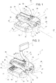
Figure 1 shows, in perspective view, a preferred embodiment of the supporting member to support a cabling, according to this invention; -
Figure 2 is similar toFigure 1 and shows an assembly formed by the supporting member ofFigure 1 and by a cabling coupled to such supporting member; and -
Figure 3 shows, in rear perspective view, an airbag module, that forms part of a vehicle steering wheel and is provided with the assembly ofFigure 2 ; and -
Figure 4 shows an assembly phase to couple the airbag module ofFigure 3 to a remaining part of the steering wheel. - In
Figure 1 ,reference number 1 shows a supporting member, able to support a cabling 2 (Figure 2 ), to facilitate the manual operations foreseen in order to assemble a vehicle steering wheel 3 (Figure 4 ), as will be better described below. - With reference to
Figure 3 , thecabling 2 comprises twoelectrical connectors 5 which can be electrically connected to anairbag module 6 being part of the steering wheel 3. In particular, theconnectors 5 can be connected to respective electrical connection elements (not shown) provided at arear face 7 of theairbag module 6. According to not shown variations,cabling 2 comprises a sole connector, or three connectors, instead of the twoconnectors 5. For the sake of simplicity, theconnectors 5 have been shown with the same shapes and sizes, but this invention can also be applied to cabling provided with different connectors. - Moreover, with reference to
Figure 2 , thecabling 2 comprises twocables 8 comprisingrespective end stretches 9 that respectively extend starting from theconnectors 5 and are spaced from each other. Thecables 8 comprise respective streaches that are gathered together, and/or enfolded in a sheath, so as to form asingle cable 12. Thecables 8 then end in a singleelectrical connector 13, at the opposite end with respect to theconnectors 5. - With reference to
Figures 1 and 2 , the supportingmember 1 is in plastic material, possibly reinforced, for example reinforced by fibres sunk into the plastic material itself. Preferably, the supportingmember 1 is defined as a single piece, made through a single moulding operation. - The supporting
member 1 comprises at least anattachment portion 14 having the shape and size such as to be coupled in fixed position to at least one of theconnectors 5. Preferably, for eachconnector 5, the supportingmember 1 comprises arelated attachment portion 14, and theattachment portions 14 are arranged in mutually flanked and/or aligned positions along adirection 15. In particular, theattachment portions 14 definerespective seats 16 adapted to house at least a part of theconnectors 5 in fixed positions. In order to ensure the fixing of theconnectors 5, a snap-in coupling is provided or else an interference coupling in theseats 16, in an already known manner not described in detail. - Preferably, as shown in
Figure 1 , eachseat 16 is formed by twoareas area 17 is open in a through manner along adirection 18 orthogonal todirection 15 and is engaged by an end 19 (Figure 2 ) of thecorresponding connector 5, whilearea 18 is closed on a side by ahalf shell 20, in order to cover a rear part of theconnector 5 from which thecorresponding cable 8 exits. In particular, thestretches 9 of thecables 8 form a U-shaped bend and are partly covered byrespective walls 21, that project from thehalf shells 20 and are curve shaped in order to follow at least part of such U-shaped bend. - Furthermore, the supporting
member 1 comprises anintermediate wall 23 that connects theattachment portions 14 to each other. In particular, thewall 23 has aface 24 that is flat and is parallel todirection 15 and to adirection 25, orthogonal todirections - As shown in
Figure 2 , preferablyface 24 defines a support for aportion 25 of thecable 12. - Again with reference to
Figure 1 , according to this invention, the supportingmember 1 comprises anarm 26 having twoend portions Portion 27 is fixed with respect to theattachment portions 14 and preferably extends starting from an end ofwall 23 alongdirection 25. Thearm 26 is elastically flexible, so as to enable a distancing ofportion 28 from theattachment portions 14, along amovement direction 29 that, in the specific example, is arched about an axis of rotation parallel todirection 15. Nevertheless, with configurations different fromarm 26,direction 29 could have a different orientation and/or curvature radii or may be essentially rectilinear. - The
arm 26 comprises a looped portion (30) that is elastically deformable and defines a virtual hinge to allowportion 28 to rotate alongdirection 29. Usefully, in addition,arm 26 comprises arectilinear portion 32, that defines a prolongation of the loopedportion 30, has a flat shape and is essentially orthogonal todirection 29. In greater detail, therectilinear portion 32 is joined up toportion 27 through the loopedportion 30 and, on the opposite side, it ends withportion 28. - According to an aspect of this invention, the supporting
member 1 comprises a retention device 35 to block thecable 12 coupled to thearm 26, and preferably also to thewall 23, during the elastic deformation. In the specific shown example, the retention device 35 comprises several holes through the supportingmember 1 for the insertion of cable ties 40 (Figure 2 ), that are wrapped around thecable 12. To such purpose, in particular, the retention device 35 comprises a couple ofholes 36 at the loopedportion 30 and a couple ofholes 37 at theend 28. Usefully, in addition the retention device 35 comprises a couple ofholes 38 through thewall 23. - According to not shown variations, instead of holes for the
cable ties 40, the retention device 35 comprises teeth, flaps, or similar flexible elements, that project from thearm 26 and possibly fromface 24 for the snap-in coupling and blocking of thecable 12. - After having coupled the
cabling 2 to the supportingmember 1 so as to form a single assembly, shown inFigure 2 , such an assembly is coupled to theairbag module 6, as already above-mentioned with reference toFigure 3 . - As shown in
Figure 4 , besides theairbag module 6, the steering wheel 3 comprises astructure 41 having anannular element 44 that defines at least one holding portion able to be gripped by a driver to rotate the steering wheel 3 about an axis ofrotation 46. - Moreover, the
structure 41 has ahub 48, which is connected to theelement 44 through one ormore spokes 49, has acavity 50 open frontally and is able to be coupled in the vehicle, in an already known way and not described in detail, in angularly fixed and coaxial position with respect to asteering column 51. - Prior to coupling the
hub 48, a driving switch device 52 (partly and schematically shown) is arranged around thesteering column 51 in fixed position. Thedriving switch device 52 carries aconnector 53, adapted to be electrically connected to theconnector 13 to transmit electrical supply and/or electrical signals to theairbag module 6 via thecabling 2. In particular, after the assembly of thestructure 41 on thesteering column 51, theconnector 53 is arranged in anopening 54 obtained through thestructure 41 of the steering wheel 3. - After the assembly of the
structure 41, theairbag module 6 must be coupled to thehub 48 so as to close thecavity 50 and cover an axial end of thesteering column 51. In particular, theairbag module 6 comprises anairbag device 55 and apressurised control device 56 being operable by the driver to activate an external audible warning device (hooter). - During the assembly operations of the
airbag module 6, the latter is supported (for example manually) so as to keep therear face 7 in a position close to thehub 48, but at such a distance so as to be able to manually grasp thecable 12 and/or thearm 26 and to be able to, immediately after, bring closer and electrically connect theconnector 13 to theconnector 53. During this step, thearm 26 can be elastically deformed in a relatively simple way to bring closer theconnector 13 to thehub 48. The traction on thearm 26 along thedirection 29 transfers itself to theattachment portions 14 and, from the latter, to theconnectors 5. The flexibility/rigidity of thearm 26 is determined during design so as to limit excessive elastic forces that may cause risks of electrical disconnection of theconnectors 5 from theairbag module 6 and/or risks of uncoupling of the supportingmember 1 from theconnectors 5. - When the
connectors airbag module 6 is positioned so as to close thecavity 50 and is then fixed to thehub 48, according to a already known mode not described in detail. During the bringing closer of therear face 7 to thehub 48, thearm 26 returns automatically to its undeformed state, shown inFigures 1 and 2 , carrying with it thecable 12 to which it is attached. Thereby,cable 12 is not free, during the closing ofcavity 50, but it is guided by the elastic force of thearm 26 along a defined trajectory (that is along direction 29) and towards a defined position (that is the one corresponding to the undeformed state of the arm 26). - It is therefore clear how the
cable 12 does not risk any pinching and, hence, any damage during the coupling operations of theairbag module 6. Indeed, thecable 12 is forced to remain in a limited space, determined during design and essentially defined by the degree of flexibility and by the size of thearm 26. - Other advantages are then clear for a skilled person in the art on the basis of the other characteristics displayed above. In particular, the supporting
member 1 is relatively compact. Moreover, the specific shape of thearm 26 shown in the annexed drawings is relatively simple to make and then to use during the assembly of theairbag module 6. Furthermore, the supportingmember 1 is shaped so as to protect thecables 8 as much as possible, besides guiding the movements ofcable 12 through the elastic deformation of thearm 26. - Finally, from the foregoing it comes clear that modifications and variations can be made to the supporting
member 1 which are not beyond the protection field of this invention, as defined in the appended claims. - In particular, the shape of the
arm 26, for example the number and the position of the loopedportions 30, may be different from what has been shown as an example; and/or thewalls 21 could be absent; and/or theattachment portions 14 could have different shapes from what has been shown, in general to adapt to electrical connectors of a different kind from theconnectors 5. - Moreover, the supporting
member 1 could be shaped so as to electrically connect thecabling 2 to theconnector 53 before mounting theairbag module 6 over thehub 48, and to then exploit the flexibility of thearm 26 to connect thecabling 2 to theairbag module 6 during the fixing operations of the latter.
Claims (10)
- A supporting member (1) to support cabling (2), which comprises:- at least one cable (12);- a first and a second connector (5,13) electrically connected to each other through said cable (12);the supporting member being characterised in that it comprises:- an attachment portion (14) having the shape and size such as to be connected, in use, to said first connector (5) ;- an arm (26) comprising a first and a second end portion (27,28) opposite to each other; said first end portion (27) being fixed with respect to said attachment portion (14); the arm being elastically flexible so as to enable a distancing of said second end portion (28) from said attachment portion (14);- retention means (35) to keep said cable (12) coupled to said arm (26).
- The supporting member according to claim 1, characterised in that said arm (26) comprises at least one looped portion (30) that is elastically deformable.
- The supporting member according to claim 2, characterised in that said retention means (35) comprise first retention means (36) carried by said looped portion (30) .
- The supporting member according to claim 2 or 3, characterised in that said arm (26) comprises at least one rectilinear portion (32), which extends like a prolongation of said looped portion (30).
- The supporting member according to claim 4, characterised in that said rectilinear portion (32) has a flat shape and is essentially orthogonal to a direction (29) along which said second end portion (28) moves when said arm (26) is elastically deformed.
- The supporting member according to any one of the preceding claims, characterised in that said retention means (35) comprise second retention means (37) carried by said second end portion (28).
- The supporting member according to any one of the preceding claims, characterised in that it comprises two attachment portions (14), arranged in mutually flanked positions and having such shapes and sizes as to support, in use, respective first connectors (5) of said cabling (2); and a supporting wall (23) arranged in an intermediate position between said attachment portions (14).
- The supporting member according to claim 7, characterised in that said arm (26) extends overhanging from said supporting wall (23); and in that it comprises third retention means (38) carried by said supporting wall (23) to keep said cable (12) coupled to said supporting wall (23).
- A vehicle steering wheel comprising:- a structure (41) able to be held by a driver and comprising a hub (43), able to be coupled to a steering column (51) in coaxial and angularly fixed position;- an airbag module (6) fixed or fixable to said hub (48);- a cabling (2) comprising at least one cable (12), a first connector (5) and a second connector (13) electrically connected to said first connector (5) through said cable (12);- a supporting member (1), according to any one of the preceding claims, and coupled to said cabling (2);wherein said first connector (5) is electrically connected to said airbag module (6).
- Assembly method to assemble a vehicle's steering wheel according to claim 9, characterised in that it comprises the steps of:- arranging a driving switch device (52) around a steering column (51), said driving switch device (52) carrying at least one third connector (53);- coupling said hub (48) to said steering column (51) in coaxial position and fixed angularly and over said driving switch device (52);- bringing closer and electrically connect said second connector (13) to said third connector (53), elastically deforming said arm (26);- bringing closer and fixing said airbag module (6) to said hub (48), after having connected said second and third connector (13,53).
Priority Applications (1)
| Application Number | Priority Date | Filing Date | Title |
|---|---|---|---|
| EP18181116.7A EP3590768B1 (en) | 2018-07-02 | 2018-07-02 | Supporting member to support a cabling, vehicle steering wheel which is provided with such supporting member, and assembly method to assemble such vehicle steering wheel |
Applications Claiming Priority (1)
| Application Number | Priority Date | Filing Date | Title |
|---|---|---|---|
| EP18181116.7A EP3590768B1 (en) | 2018-07-02 | 2018-07-02 | Supporting member to support a cabling, vehicle steering wheel which is provided with such supporting member, and assembly method to assemble such vehicle steering wheel |
Publications (2)
| Publication Number | Publication Date |
|---|---|
| EP3590768A1 true EP3590768A1 (en) | 2020-01-08 |
| EP3590768B1 EP3590768B1 (en) | 2022-05-18 |
Family
ID=63449166
Family Applications (1)
| Application Number | Title | Priority Date | Filing Date |
|---|---|---|---|
| EP18181116.7A Active EP3590768B1 (en) | 2018-07-02 | 2018-07-02 | Supporting member to support a cabling, vehicle steering wheel which is provided with such supporting member, and assembly method to assemble such vehicle steering wheel |
Country Status (1)
| Country | Link |
|---|---|
| EP (1) | EP3590768B1 (en) |
Citations (2)
| Publication number | Priority date | Publication date | Assignee | Title |
|---|---|---|---|---|
| US20170138379A1 (en) * | 2015-11-16 | 2017-05-18 | Daiwa Kasei Kogyo Kabushiki Kaisha | Clips |
| WO2017093313A1 (en) * | 2015-12-02 | 2017-06-08 | Trw Automotive Safety Systems Gmbh | Cable conduit device for connection cables of an airbag module, wiring system, airbag module, and steering wheel or vehicle comprising a cable conduit device of said type |
-
2018
- 2018-07-02 EP EP18181116.7A patent/EP3590768B1/en active Active
Patent Citations (2)
| Publication number | Priority date | Publication date | Assignee | Title |
|---|---|---|---|---|
| US20170138379A1 (en) * | 2015-11-16 | 2017-05-18 | Daiwa Kasei Kogyo Kabushiki Kaisha | Clips |
| WO2017093313A1 (en) * | 2015-12-02 | 2017-06-08 | Trw Automotive Safety Systems Gmbh | Cable conduit device for connection cables of an airbag module, wiring system, airbag module, and steering wheel or vehicle comprising a cable conduit device of said type |
Also Published As
| Publication number | Publication date |
|---|---|
| EP3590768B1 (en) | 2022-05-18 |
Similar Documents
| Publication | Publication Date | Title |
|---|---|---|
| JP6756828B2 (en) | A wiring system, an airbag module, and a steering wheel or vehicle, including a cable conduit device for connecting cables of the airbag module, as well as a cable conduit device of the type described above. | |
| US4969795A (en) | Industrial robot equipped with a cable extending means | |
| US6619353B1 (en) | Chain for tire | |
| EP3472089B1 (en) | Hose guiding devi ce for a crane tool | |
| KR20160038757A (en) | Robot | |
| JP6923489B2 (en) | Horizontal articulated robot | |
| US20180072128A1 (en) | Active roll stabilizer of a motor vehicle and method for assembly | |
| EP3422509B1 (en) | Cable-assembly for robotic installation | |
| KR20180124760A (en) | Cable channel module, modular assembly of cable channel modules and method of assembling a modular assembly | |
| JPH05146031A (en) | Connector for conductive cable | |
| EP3590768B1 (en) | Supporting member to support a cabling, vehicle steering wheel which is provided with such supporting member, and assembly method to assemble such vehicle steering wheel | |
| EP2555346A1 (en) | Rotary connector device | |
| WO1998019090A1 (en) | Cable assembly holder for an industrial robot | |
| EP3249254B1 (en) | Mechanical link | |
| JP7472739B2 (en) | Wire Harness | |
| JP2640870B2 (en) | A device that holds and lays a number of cables that are guided together in the built-in space of a car | |
| US6960108B1 (en) | Protective containment device for wires and hoses of an outboard motor | |
| KR101149693B1 (en) | Cable or the like protection guide device | |
| AU2017339055B2 (en) | Trailer coupling having a connection device | |
| JP2001128350A (en) | Flat cable winder | |
| EP1241055B1 (en) | Electric connector system for the steering wheel of a vehicle | |
| JPH071380A (en) | robot | |
| EP3459142B1 (en) | Audio headset electrical cable termination | |
| FR2790780B1 (en) | MOTOR VEHICLE OPENING HANDLE COMPRISING A MOUNTING GRIP MEMBER PIVOTING AROUND TWO SEPARATE AXES | |
| KR100663726B1 (en) | Cable Readers for Electric Home Wiring |
Legal Events
| Date | Code | Title | Description |
|---|---|---|---|
| PUAI | Public reference made under article 153(3) epc to a published international application that has entered the european phase |
Free format text: ORIGINAL CODE: 0009012 |
|
| STAA | Information on the status of an ep patent application or granted ep patent |
Free format text: STATUS: THE APPLICATION HAS BEEN PUBLISHED |
|
| AK | Designated contracting states |
Kind code of ref document: A1 Designated state(s): AL AT BE BG CH CY CZ DE DK EE ES FI FR GB GR HR HU IE IS IT LI LT LU LV MC MK MT NL NO PL PT RO RS SE SI SK SM TR |
|
| AX | Request for extension of the european patent |
Extension state: BA ME |
|
| STAA | Information on the status of an ep patent application or granted ep patent |
Free format text: STATUS: REQUEST FOR EXAMINATION WAS MADE |
|
| 17P | Request for examination filed |
Effective date: 20200707 |
|
| RBV | Designated contracting states (corrected) |
Designated state(s): AL AT BE BG CH CY CZ DE DK EE ES FI FR GB GR HR HU IE IS IT LI LT LU LV MC MK MT NL NO PL PT RO RS SE SI SK SM TR |
|
| GRAP | Despatch of communication of intention to grant a patent |
Free format text: ORIGINAL CODE: EPIDOSNIGR1 |
|
| STAA | Information on the status of an ep patent application or granted ep patent |
Free format text: STATUS: GRANT OF PATENT IS INTENDED |
|
| INTG | Intention to grant announced |
Effective date: 20211207 |
|
| GRAS | Grant fee paid |
Free format text: ORIGINAL CODE: EPIDOSNIGR3 |
|
| GRAA | (expected) grant |
Free format text: ORIGINAL CODE: 0009210 |
|
| STAA | Information on the status of an ep patent application or granted ep patent |
Free format text: STATUS: THE PATENT HAS BEEN GRANTED |
|
| AK | Designated contracting states |
Kind code of ref document: B1 Designated state(s): AL AT BE BG CH CY CZ DE DK EE ES FI FR GB GR HR HU IE IS IT LI LT LU LV MC MK MT NL NO PL PT RO RS SE SI SK SM TR |
|
| REG | Reference to a national code |
Ref country code: GB Ref legal event code: FG4D |
|
| REG | Reference to a national code |
Ref country code: CH Ref legal event code: EP |
|
| REG | Reference to a national code |
Ref country code: IE Ref legal event code: FG4D |
|
| REG | Reference to a national code |
Ref country code: DE Ref legal event code: R096 Ref document number: 602018035687 Country of ref document: DE |
|
| REG | Reference to a national code |
Ref country code: AT Ref legal event code: REF Ref document number: 1492992 Country of ref document: AT Kind code of ref document: T Effective date: 20220615 |
|
| REG | Reference to a national code |
Ref country code: LT Ref legal event code: MG9D |
|
| REG | Reference to a national code |
Ref country code: NL Ref legal event code: MP Effective date: 20220518 |
|
| REG | Reference to a national code |
Ref country code: AT Ref legal event code: MK05 Ref document number: 1492992 Country of ref document: AT Kind code of ref document: T Effective date: 20220518 |
|
| PG25 | Lapsed in a contracting state [announced via postgrant information from national office to epo] |
Ref country code: SE Free format text: LAPSE BECAUSE OF FAILURE TO SUBMIT A TRANSLATION OF THE DESCRIPTION OR TO PAY THE FEE WITHIN THE PRESCRIBED TIME-LIMIT Effective date: 20220518 Ref country code: PT Free format text: LAPSE BECAUSE OF FAILURE TO SUBMIT A TRANSLATION OF THE DESCRIPTION OR TO PAY THE FEE WITHIN THE PRESCRIBED TIME-LIMIT Effective date: 20220919 Ref country code: NO Free format text: LAPSE BECAUSE OF FAILURE TO SUBMIT A TRANSLATION OF THE DESCRIPTION OR TO PAY THE FEE WITHIN THE PRESCRIBED TIME-LIMIT Effective date: 20220818 Ref country code: NL Free format text: LAPSE BECAUSE OF FAILURE TO SUBMIT A TRANSLATION OF THE DESCRIPTION OR TO PAY THE FEE WITHIN THE PRESCRIBED TIME-LIMIT Effective date: 20220518 Ref country code: LT Free format text: LAPSE BECAUSE OF FAILURE TO SUBMIT A TRANSLATION OF THE DESCRIPTION OR TO PAY THE FEE WITHIN THE PRESCRIBED TIME-LIMIT Effective date: 20220518 Ref country code: HR Free format text: LAPSE BECAUSE OF FAILURE TO SUBMIT A TRANSLATION OF THE DESCRIPTION OR TO PAY THE FEE WITHIN THE PRESCRIBED TIME-LIMIT Effective date: 20220518 Ref country code: GR Free format text: LAPSE BECAUSE OF FAILURE TO SUBMIT A TRANSLATION OF THE DESCRIPTION OR TO PAY THE FEE WITHIN THE PRESCRIBED TIME-LIMIT Effective date: 20220819 Ref country code: FI Free format text: LAPSE BECAUSE OF FAILURE TO SUBMIT A TRANSLATION OF THE DESCRIPTION OR TO PAY THE FEE WITHIN THE PRESCRIBED TIME-LIMIT Effective date: 20220518 Ref country code: ES Free format text: LAPSE BECAUSE OF FAILURE TO SUBMIT A TRANSLATION OF THE DESCRIPTION OR TO PAY THE FEE WITHIN THE PRESCRIBED TIME-LIMIT Effective date: 20220518 Ref country code: BG Free format text: LAPSE BECAUSE OF FAILURE TO SUBMIT A TRANSLATION OF THE DESCRIPTION OR TO PAY THE FEE WITHIN THE PRESCRIBED TIME-LIMIT Effective date: 20220818 Ref country code: AT Free format text: LAPSE BECAUSE OF FAILURE TO SUBMIT A TRANSLATION OF THE DESCRIPTION OR TO PAY THE FEE WITHIN THE PRESCRIBED TIME-LIMIT Effective date: 20220518 |
|
| PG25 | Lapsed in a contracting state [announced via postgrant information from national office to epo] |
Ref country code: RS Free format text: LAPSE BECAUSE OF FAILURE TO SUBMIT A TRANSLATION OF THE DESCRIPTION OR TO PAY THE FEE WITHIN THE PRESCRIBED TIME-LIMIT Effective date: 20220518 Ref country code: PL Free format text: LAPSE BECAUSE OF FAILURE TO SUBMIT A TRANSLATION OF THE DESCRIPTION OR TO PAY THE FEE WITHIN THE PRESCRIBED TIME-LIMIT Effective date: 20220518 Ref country code: LV Free format text: LAPSE BECAUSE OF FAILURE TO SUBMIT A TRANSLATION OF THE DESCRIPTION OR TO PAY THE FEE WITHIN THE PRESCRIBED TIME-LIMIT Effective date: 20220518 Ref country code: IS Free format text: LAPSE BECAUSE OF FAILURE TO SUBMIT A TRANSLATION OF THE DESCRIPTION OR TO PAY THE FEE WITHIN THE PRESCRIBED TIME-LIMIT Effective date: 20220918 |
|
| PG25 | Lapsed in a contracting state [announced via postgrant information from national office to epo] |
Ref country code: SM Free format text: LAPSE BECAUSE OF FAILURE TO SUBMIT A TRANSLATION OF THE DESCRIPTION OR TO PAY THE FEE WITHIN THE PRESCRIBED TIME-LIMIT Effective date: 20220518 Ref country code: SK Free format text: LAPSE BECAUSE OF FAILURE TO SUBMIT A TRANSLATION OF THE DESCRIPTION OR TO PAY THE FEE WITHIN THE PRESCRIBED TIME-LIMIT Effective date: 20220518 Ref country code: RO Free format text: LAPSE BECAUSE OF FAILURE TO SUBMIT A TRANSLATION OF THE DESCRIPTION OR TO PAY THE FEE WITHIN THE PRESCRIBED TIME-LIMIT Effective date: 20220518 Ref country code: EE Free format text: LAPSE BECAUSE OF FAILURE TO SUBMIT A TRANSLATION OF THE DESCRIPTION OR TO PAY THE FEE WITHIN THE PRESCRIBED TIME-LIMIT Effective date: 20220518 Ref country code: DK Free format text: LAPSE BECAUSE OF FAILURE TO SUBMIT A TRANSLATION OF THE DESCRIPTION OR TO PAY THE FEE WITHIN THE PRESCRIBED TIME-LIMIT Effective date: 20220518 Ref country code: CZ Free format text: LAPSE BECAUSE OF FAILURE TO SUBMIT A TRANSLATION OF THE DESCRIPTION OR TO PAY THE FEE WITHIN THE PRESCRIBED TIME-LIMIT Effective date: 20220518 |
|
| REG | Reference to a national code |
Ref country code: DE Ref legal event code: R097 Ref document number: 602018035687 Country of ref document: DE |
|
| PG25 | Lapsed in a contracting state [announced via postgrant information from national office to epo] |
Ref country code: MC Free format text: LAPSE BECAUSE OF FAILURE TO SUBMIT A TRANSLATION OF THE DESCRIPTION OR TO PAY THE FEE WITHIN THE PRESCRIBED TIME-LIMIT Effective date: 20220518 |
|
| REG | Reference to a national code |
Ref country code: CH Ref legal event code: PL |
|
| PLBE | No opposition filed within time limit |
Free format text: ORIGINAL CODE: 0009261 |
|
| STAA | Information on the status of an ep patent application or granted ep patent |
Free format text: STATUS: NO OPPOSITION FILED WITHIN TIME LIMIT |
|
| REG | Reference to a national code |
Ref country code: BE Ref legal event code: MM Effective date: 20220731 |
|
| PG25 | Lapsed in a contracting state [announced via postgrant information from national office to epo] |
Ref country code: AL Free format text: LAPSE BECAUSE OF FAILURE TO SUBMIT A TRANSLATION OF THE DESCRIPTION OR TO PAY THE FEE WITHIN THE PRESCRIBED TIME-LIMIT Effective date: 20220518 |
|
| 26N | No opposition filed |
Effective date: 20230221 |
|
| GBPC | Gb: european patent ceased through non-payment of renewal fee |
Effective date: 20220818 |
|
| PG25 | Lapsed in a contracting state [announced via postgrant information from national office to epo] |
Ref country code: LU Free format text: LAPSE BECAUSE OF NON-PAYMENT OF DUE FEES Effective date: 20220702 Ref country code: LI Free format text: LAPSE BECAUSE OF NON-PAYMENT OF DUE FEES Effective date: 20220731 Ref country code: CH Free format text: LAPSE BECAUSE OF NON-PAYMENT OF DUE FEES Effective date: 20220731 |
|
| PG25 | Lapsed in a contracting state [announced via postgrant information from national office to epo] |
Ref country code: SI Free format text: LAPSE BECAUSE OF FAILURE TO SUBMIT A TRANSLATION OF THE DESCRIPTION OR TO PAY THE FEE WITHIN THE PRESCRIBED TIME-LIMIT Effective date: 20220518 Ref country code: BE Free format text: LAPSE BECAUSE OF NON-PAYMENT OF DUE FEES Effective date: 20220731 |
|
| PG25 | Lapsed in a contracting state [announced via postgrant information from national office to epo] |
Ref country code: IE Free format text: LAPSE BECAUSE OF NON-PAYMENT OF DUE FEES Effective date: 20220702 |
|
| PG25 | Lapsed in a contracting state [announced via postgrant information from national office to epo] |
Ref country code: GB Free format text: LAPSE BECAUSE OF NON-PAYMENT OF DUE FEES Effective date: 20220818 |
|
| PG25 | Lapsed in a contracting state [announced via postgrant information from national office to epo] |
Ref country code: HU Free format text: LAPSE BECAUSE OF FAILURE TO SUBMIT A TRANSLATION OF THE DESCRIPTION OR TO PAY THE FEE WITHIN THE PRESCRIBED TIME-LIMIT; INVALID AB INITIO Effective date: 20180702 |
|
| PG25 | Lapsed in a contracting state [announced via postgrant information from national office to epo] |
Ref country code: MK Free format text: LAPSE BECAUSE OF FAILURE TO SUBMIT A TRANSLATION OF THE DESCRIPTION OR TO PAY THE FEE WITHIN THE PRESCRIBED TIME-LIMIT Effective date: 20220511 Ref country code: CY Free format text: LAPSE BECAUSE OF FAILURE TO SUBMIT A TRANSLATION OF THE DESCRIPTION OR TO PAY THE FEE WITHIN THE PRESCRIBED TIME-LIMIT Effective date: 20220511 |
|
| PG25 | Lapsed in a contracting state [announced via postgrant information from national office to epo] |
Ref country code: MT Free format text: LAPSE BECAUSE OF FAILURE TO SUBMIT A TRANSLATION OF THE DESCRIPTION OR TO PAY THE FEE WITHIN THE PRESCRIBED TIME-LIMIT Effective date: 20220511 |
|
| PG25 | Lapsed in a contracting state [announced via postgrant information from national office to epo] |
Ref country code: BG Free format text: LAPSE BECAUSE OF FAILURE TO SUBMIT A TRANSLATION OF THE DESCRIPTION OR TO PAY THE FEE WITHIN THE PRESCRIBED TIME-LIMIT Effective date: 20220518 |
|
| PG25 | Lapsed in a contracting state [announced via postgrant information from national office to epo] |
Ref country code: BG Free format text: LAPSE BECAUSE OF FAILURE TO SUBMIT A TRANSLATION OF THE DESCRIPTION OR TO PAY THE FEE WITHIN THE PRESCRIBED TIME-LIMIT Effective date: 20220518 |
|
| PGFP | Annual fee paid to national office [announced via postgrant information from national office to epo] |
Ref country code: FR Payment date: 20250620 Year of fee payment: 8 |
|
| PGFP | Annual fee paid to national office [announced via postgrant information from national office to epo] |
Ref country code: DE Payment date: 20250620 Year of fee payment: 8 |
|
| PGFP | Annual fee paid to national office [announced via postgrant information from national office to epo] |
Ref country code: IT Payment date: 20250619 Year of fee payment: 8 |
|
| PG25 | Lapsed in a contracting state [announced via postgrant information from national office to epo] |
Ref country code: TR Free format text: LAPSE BECAUSE OF FAILURE TO SUBMIT A TRANSLATION OF THE DESCRIPTION OR TO PAY THE FEE WITHIN THE PRESCRIBED TIME-LIMIT Effective date: 20220518 |
|
| REG | Reference to a national code |
Ref country code: DE Ref legal event code: R081 Ref document number: 602018035687 Country of ref document: DE Owner name: STELLANTIS EUROPE S.P.A., IT Free format text: FORMER OWNER: FCA ITALY S.P.A., TORINO, IT |