EP3590720A1 - Inkjet recording device - Google Patents
Inkjet recording device Download PDFInfo
- Publication number
- EP3590720A1 EP3590720A1 EP19179519.4A EP19179519A EP3590720A1 EP 3590720 A1 EP3590720 A1 EP 3590720A1 EP 19179519 A EP19179519 A EP 19179519A EP 3590720 A1 EP3590720 A1 EP 3590720A1
- Authority
- EP
- European Patent Office
- Prior art keywords
- color
- ink
- ink ejecting
- special
- ejecting portion
- Prior art date
- Legal status (The legal status is an assumption and is not a legal conclusion. Google has not performed a legal analysis and makes no representation as to the accuracy of the status listed.)
- Granted
Links
Images




Classifications
-
- B—PERFORMING OPERATIONS; TRANSPORTING
- B41—PRINTING; LINING MACHINES; TYPEWRITERS; STAMPS
- B41J—TYPEWRITERS; SELECTIVE PRINTING MECHANISMS, i.e. MECHANISMS PRINTING OTHERWISE THAN FROM A FORME; CORRECTION OF TYPOGRAPHICAL ERRORS
- B41J2/00—Typewriters or selective printing mechanisms characterised by the printing or marking process for which they are designed
- B41J2/005—Typewriters or selective printing mechanisms characterised by the printing or marking process for which they are designed characterised by bringing liquid or particles selectively into contact with a printing material
- B41J2/01—Ink jet
- B41J2/21—Ink jet for multi-colour printing
- B41J2/2103—Features not dealing with the colouring process per se, e.g. construction of printers or heads, driving circuit adaptations
-
- B—PERFORMING OPERATIONS; TRANSPORTING
- B41—PRINTING; LINING MACHINES; TYPEWRITERS; STAMPS
- B41J—TYPEWRITERS; SELECTIVE PRINTING MECHANISMS, i.e. MECHANISMS PRINTING OTHERWISE THAN FROM A FORME; CORRECTION OF TYPOGRAPHICAL ERRORS
- B41J2/00—Typewriters or selective printing mechanisms characterised by the printing or marking process for which they are designed
- B41J2/005—Typewriters or selective printing mechanisms characterised by the printing or marking process for which they are designed characterised by bringing liquid or particles selectively into contact with a printing material
- B41J2/01—Ink jet
- B41J2/21—Ink jet for multi-colour printing
-
- B—PERFORMING OPERATIONS; TRANSPORTING
- B41—PRINTING; LINING MACHINES; TYPEWRITERS; STAMPS
- B41J—TYPEWRITERS; SELECTIVE PRINTING MECHANISMS, i.e. MECHANISMS PRINTING OTHERWISE THAN FROM A FORME; CORRECTION OF TYPOGRAPHICAL ERRORS
- B41J2/00—Typewriters or selective printing mechanisms characterised by the printing or marking process for which they are designed
- B41J2/005—Typewriters or selective printing mechanisms characterised by the printing or marking process for which they are designed characterised by bringing liquid or particles selectively into contact with a printing material
- B41J2/01—Ink jet
- B41J2/21—Ink jet for multi-colour printing
- B41J2/2132—Print quality control characterised by dot disposition, e.g. for reducing white stripes or banding
- B41J2/2146—Print quality control characterised by dot disposition, e.g. for reducing white stripes or banding for line print heads
Definitions
- the color mixing in image formation by the inkjet recording device 1 is expressed by using an effect that, by causing inks in different colors to reach within a predetermined neighboring range on the recording medium m, a color looks as if the different colors are mixed with each other for an observer (from an ordinary macro viewpoint) of the recording medium m. Therefore, the inks do not necessarily have to be ejected so that the inks in a liquid state are united on the recording medium m but the inks may be ejected in a form in which the inks in different colors having reached neighboring positions (or positions at least partially overlapped) are solidified at timing separately from each other (that is, in the form not united in the liquid state).
- a reactive dye ink suitably used for the recording medium m of natural fibers such as cotton and hemp is used.
- dye molecules are covalent-bonded with molecules of the recording medium by executing steaming processing (heating and humidifying) after being ejected onto the recording medium m, and the recording medium m can be colored in a stable state.
- the inkjet recording device 1 includes a conveyance driving portion 101 and a rotary encoder 15 provided in the conveyer 10, a head controller 24 and a head driving portion 221 provided in the head unit 21, a controller 30, an image processor 41, an operation display portion 42, an input/output interface 43, a bus 44 and the like.
- the CPU 31 causes programs for various types of control and setting data stored in the ROM 33 to be read out and stored in the RAM 32 and executes various types of calculation processing by executing the programs. Moreover, the CPU 31 integrally controls the entire operation of the inkjet recording device 1.
- the input/output interface 43 mediates transmission/reception of data between the external device 2 and the controller 30.
- the input/output interface 43 is configured by any of various serial interfaces and various parallel interfaces or a combination of them, for example.
- the inks in the special color (B) and the opposite primary color (Y) not to be mixed are ejected from the head units 21B and 21Y, respectively, with the positional relationship (P2 and P6) with a large interval with respect to the conveying direction and thus, even if the impact positions of the inks ejected from these head units 21B and 21Y are displaced in the width direction due to the diagonal moving of the recording medium m, it does not cause a color shift in the recorded image.
- the inks in the special color and in the opposite color which are not to be mixed are ejected, respectively, from the head units 21 with the positional relationship with the large interval with respect to the conveying direction and thus, even if the impact position displacement in the width direction of the inks ejected from these head units 21 occurs due to the diagonal moving of the recording medium m, it does not cause a color shift in the recorded image.
- Figs. 10A to 10D are diagrams illustrating the arrangement order of the head units 21 in this variation.
- the inks in five colors of Y, M, C, K, and Gy may be used without using the ink in the special color.
- the arrangement order of the five head units 21 in this case may be K, M, Gy, C, and Y from the upstream side in the conveying direction as illustrated in Fig. 11 , for example.
- the number of special colors is not limited to one or two colors, but three or more colors may be used.
- the ink in the special color belonging to the hue range A3 may be further used, for example.
Landscapes
- Engineering & Computer Science (AREA)
- Quality & Reliability (AREA)
- Ink Jet (AREA)
Abstract
Description
- The present invention relates to an inkjet recording device.
- Conventionally, an inkjet recording device which records images and the like by causing an ink to be ejected from a nozzle provided in an ink ejecting portion and to reach a desired position on a recording medium conveyed by a conveyer. As one of the inkjet recording devices, such a device is known that a plurality of the ink ejecting portions each of which ejects inks in colors different from each other is provided at different positions with respect to a conveying direction of the recording medium, and a color image can be recorded on the recording medium being conveyed by causing the ink to be ejected from each of the ink ejecting portions at appropriate timing.
- In such inkjet recording devices, in addition to the ink ejecting portions which eject inks in process colors consisting of three primary colors (yellow, magenta, cyan) and black, such an art is known that an ink ejecting portion which ejects an ink in gray which is an achromatic color with brightness higher than black is further provided, and by enabling recording of an image in color in which at least one of the three primary colors and gray are mixed, color reproducibility of a recorded image is improved (Japanese Patent Laid-Open No.
2012-920 - However, if the number of the ink ejecting portions is increased and the larger a distance between the colors with respect to the conveying direction becomes, the more a positional displacement amount of the recording medium with respect to a width direction orthogonal to the conveying direction tends to increase.
- Since displacement occurs also in an impact position of the ink in accordance with such positional displacement of the recording medium, colors of the inks ejected from each of the plurality of ink ejecting portions are not mixed as desired, which leads to occurrence of a color shift in the recorded image. In particular, in the inkjet recording device which uses the gray ink in addition to the inks in the process colors, when the distance between the ink ejecting portion which ejects the gray ink and the ink ejecting portions which eject inks in the three primary colors becomes larger, the color shift occurs since gray and the three primary colors are not mixed appropriately. As a result, an improvement effect of color reproducibility by the gray ink cannot be obtained easily anymore, and there is a problem that an image quality lowers.
- An object of the present invention is to provide an inkjet recording device which can suppress deterioration of an image quality deterioration of a recorded image.
- In order to achieve at least one of the aforementioned objects, according to an aspect of the present invention, an inkjet recording device is:
- an inkjet recording device which is capable of recording an image including a portion in which at least one color in three primary colors of yellow, magenta, and cyan is mixed with gray by using inks in yellow, magenta, cyan, black, and gray on a recording medium, including:
- a conveyer which conveys the recording medium; and
- five ink ejecting portions each of which ejects ink in one color different from each other in yellow, magenta, cyan, black, and gray to the recording medium conveyed by the conveyer, in which
- the five ink ejecting portions are provided at positions different from each other with respect to a conveying direction of the recording medium by the conveyer; and
- the gray ink ejecting portion which ejects ink in gray in the five ink ejecting portions is disposed inside an arrangement range of a primary-color ink ejecting portion group consisting of the three ink ejecting portions which eject inks in the three primary colors in the five ink ejecting portions with respect to the conveying direction.
- The advantages and features provided by one or more embodiments of the invention will become more fully understood from the detailed description given hereinbelow and the appended drawings which are given by way of illustration only, and thus are not intended as a definition of the limits of the present invention.
-
Fig. 1 is a diagram illustrating outline configuration of an inkjet recording device; -
Fig. 2 is a schematic diagram illustrating configuration of a head unit; -
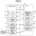
Fig. 3 is a block diagram illustrating major functional configuration of the inkjet recording device; -
Fig. 4 is a diagram illustrating a position of a B which is a special color in a hue circle; -
Fig. 5 is a diagram illustrating an arrangement order of the head unit; -
Fig. 6 is a diagram illustrating another example of the arrangement order of the head unit; -
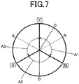
Fig. 7 is a diagram illustrating positions of O and B which are special colors in avariation 1 in the hue circle; -
Fig. 8A is a diagram illustrating the arrangement order of the head unit in thevariation 1; -
Fig. 8B is a diagram illustrating the arrangement order of the head unit in thevariation 1; -
Fig. 8C is a diagram illustrating the arrangement order of the head unit in thevariation 1; -
Fig. 8D is a diagram illustrating the arrangement order of the head unit in thevariation 1; -
Fig. 9 is a diagram illustrating positions of R and V which are special colors in avariation 2 in the hue circle; -
Fig. 10A is a diagram illustrating the arrangement order of the head unit in thevariation 2; -
Fig. 10B is a diagram illustrating the arrangement order of the head unit in thevariation 2; -
Fig. 10C is a diagram illustrating the arrangement order of the head unit in thevariation 2; -
Fig. 10D is a diagram illustrating the arrangement order of the head unit in thevariation 2; and -
Fig. 11 is a diagram illustrating another example of the arrangement order of the head unit. - Hereinafter, one or more embodiments of the present invention will be described with reference to the drawings. However, the scope of the invention is not limited to the disclosed embodiments.
- Hereinafter, embodiments of an inkjet recording device of the present invention will be described on the basis of the drawings.
-
Fig. 1 is a diagram illustrating outline configuration of theinkjet recording device 1 which is an embodiment of the present invention. - The
inkjet recording device 1 includes aconveyer 10, arecording portion 20, acontroller 30 and the like. - The
conveyer 10 includes adriving roller 11, a drivenroller 12, aconveyer belt 13, aconveyer motor 14, arotary encoder 15, apressing roller 16, a separatingroller 17 and the like. - The
driving roller 11 is rotated around a rotation shaft by driving of theconveyer motor 14. Theconveyer belt 13 is a ring-shaped belt supported by thedriving roller 11 and the driven roller 12 (hereinafter, collectively referred to also as conveyer rollers) on an inner side and circularly moved around by following a rotating operation of thedriving roller 11. The drivenroller 12 is rotated around a rotation shaft in parallel with the rotation shaft of thedriving roller 11 by following a circular movement of theconveyer belt 13. As theconveyer belt 13, those of a material which is flexibly bent on a contact surface with the conveyer roller and reliably supports a recording medium m are used, and a belt made of a resin such as rubber or a steel belt, for example, can be used. Thisconveyer belt 13 can allow the recording medium m to be stably placed on theconveyer belt 13 since it has a material and/or configuration adsorbing the recording medium m. - The
conveyer motor 14 rotates/operates thedriving roller 11 at a rotation speed according to a control signal from thecontroller 30. Theconveyer motor 14 can rotate thedriving roller 11 backward in a direction opposite to a normal conveying direction. Theconveyer 10 performs a conveying operation for conveying the recording medium m in a moving direction (conveying direction) of theconveyer belt 13 by circular movement of theconveyer belt 13 at a speed according to the rotation speed of thedriving roller 11 in a state where the recording medium m is placed on the conveyance surface of theconveyer belt 13. - The conveyance of the recording medium m may be performed intermittently in a form that the conveyance is temporarily stopped for a period during which ink ejection by the
conveyer 10 is performed, for example. The conveying operation of theconveyer 10 is assumed to include the operation of temporarily stopping the conveyance as above. - In this embodiment, a cloth is used as the recording medium m. The recording medium m is unwound from (fed out of) a roll (recording medium unwinding portion) around which the recording medium m is wound and supplied onto the
conveyer belt 13. Theconveyer 10 of this embodiment is configured capable of conveying the recording medium m with a width of approximately 2 m in a width direction orthogonal to the conveying direction and a length of the entire roll of approximately 4000 m. The recording medium m having a width smaller than 2 m in the width direction may be conveyed by theconveyer 10. Moreover, theconveyer 10 may be configured capable of conveying the recording medium m with a width larger than 2 m in the width direction or may be configured such that a maximum width of the conveyable recording medium m in the width direction is smaller than 2 m. - For the recording medium m, various mediums that can fix the ink ejected on the surface such as paper or a sheet-shaped resin and the like can be used, not limited to the aforementioned cloth. Moreover, instead of the lengthy recording medium m rewound from the roll, the recording medium m having a short length such as a sheet may be also used.
- The
rotary encoder 15 outputs a pulse signal (detection signal) to thecontroller 30 and a head controller 24 (Fig. 3 ) each time the drivingroller 11 is rotated by a predetermined angle. Configuration of therotary encoder 15 is not particularly limited but may be such that a code wheel having a plurality of slits aligned on a predetermined circumference and rotated with the drivingroller 11, a light emitter which emits light to the slits of the code wheel and a light receiver which detects the light emitted from the light emitter and passed through the slits are provided, and the pulse signal based on the detection result of the light by the light receiver is output to thecontroller 30 and thehead controller 24, for example. Here, the pulse signal can be output at a timing of rising and falling at each of two squares (A-phase and B-phase) having the same cycle as a light receiving cycle of the slit passing light and phases different from each other by 90 degrees, for example. In such configuration, the rotation direction of the drivingroller 11 can be detected by the phase of the A-phase and the B-phase. - The
pressing roller 16 removes floating from a conveyance surface such as wrinkles by pressing the recording medium m supplied to the conveyance surface of theconveyer belt 13 onto the conveyance surface. - The separating
roller 17 peels the recording medium m off the conveyance surface and sends it to a post-processing device, not shown, by pulling the recording medium m having been conveyed in a state adsorbed to theconveyer belt 13 with a predetermined pressure. In this embodiment, a drier which dries the recording medium m on which an image is recorded, a steamer which steams the recording medium m for improving coloring and fixing the ink, a washer which washes out stains, unfixed ink or the like, a cutter which cuts the recording medium m at a predetermined position and the like are provided as a post-processing device. - The
recording portion 20 includes six head units 21 (ink ejecting portions). Each of thehead units 21 has a plurality of recording elements each performing an ink ejecting operation for ejecting the ink on the basis of image data, and by means of the ink ejecting operations of the plurality of recording elements, an image recording operation for recording an image on the recording medium m conveyed by theconveyer 10 is performed. The sixhead units 21 eject inks in colors different from each other. More specifically, each of thehead units 21 ejects ink in one color different from each other in six colors of yellow (Y), magenta (M), cyan (C), black (K), gray (Gy), and blue (B). - Hereinafter, the
head units 21 ejecting the inks in Y, M, C, K, Gy, and B are also referred to as the head unit 21Y, the head unit 21M, the head unit 21C, the head unit 21K (black-ink ejecting portion), and thehead unit 21 Gy (gray-ink ejecting portion), and the head unit 21B (special-color ink ejecting portion). Moreover, a unit group consisting of the head units 21Y, 21M, and 21C ejecting the inks in the three primary colors is also referred to as a primary-color head unit group (primary-color ink ejecting portion group). Moreover, the "five ink ejecting portions" are constituted by the head units 21Y, 21M, 21C, 21K, and 21Gy excluding the head unit 21B in the sixhead units 21. - In these six colors, four colors consisting of three primary colors used for expression of a color by subtractive color mixing Y, M, and C and K (black) that cannot be obtained easily in actuality by mixture of the three primary colors are called process colors (basic colors) and are a combination of the basic colors used for recording of an image by various image forming apparatuses including the inkjet recording device. Hereinafter, one color in the three primary colors is also referred to as a "primary color".
- Moreover, Gy (gray) is an achromatic color with brightness higher than K (light color of K) and is used for expressing a color with chroma lower than the color expressed by the three primary colors by being mixed with one or two or more colors in the aforementioned three primary colors.
- Moreover, B is a color with a hue different from each of the three primary colors and is called a special color. In this embodiment, the special color is used for expressing a color different from the color expressed by the three primary colors by being mixed with at least one color in the three primary colors.
- As described above, in the
inkjet recording device 1 of this embodiment, a color obtained by mixing at least one color in the three primary colors with Gy or B can be expressed by using the inks in the process colors and the inks in Gy and B in addition to the color obtained by mixing the process colors with each other. - Here, the color mixing in image formation by the
inkjet recording device 1 is expressed by using an effect that, by causing inks in different colors to reach within a predetermined neighboring range on the recording medium m, a color looks as if the different colors are mixed with each other for an observer (from an ordinary macro viewpoint) of the recording medium m. Therefore, the inks do not necessarily have to be ejected so that the inks in a liquid state are united on the recording medium m but the inks may be ejected in a form in which the inks in different colors having reached neighboring positions (or positions at least partially overlapped) are solidified at timing separately from each other (that is, in the form not united in the liquid state). - Moreover, in this embodiment, a reactive dye ink suitably used for the recording medium m of natural fibers such as cotton and hemp is used. In the reactive dye ink, dye molecules are covalent-bonded with molecules of the recording medium by executing steaming processing (heating and humidifying) after being ejected onto the recording medium m, and the recording medium m can be colored in a stable state.
- The six
head units 21 are arranged at predetermined intervals at positions different from each other with respect to the conveying direction of the recording medium m. In such configuration, each of thehead units 21 forms an image corresponding to the color of the ink ejected from the recording element, and theinkjet recording device 1 records color images of a target to be recorded by superimposing and recording images in Y, M, C, K, Gy, and B in the same region on the recording medium m. - The arrangement order of the six
head units 21 will be described later in detail. -
Fig. 2 is a schematic diagram illustrating configuration of thehead unit 21. InFig. 2 , a plan view of theentire head unit 21 when seen from a side facing the conveyance surface of theconveyer belt 13 is illustrated. - The
head unit 21 includes 54 recording heads 22 in each of which a plurality of recording elements each ejecting the ink is provided. In each of the recording heads 22, the recording elements are aligned so as to continue over a width of approximately 72 mm in the width direction. The recording element provided in therecording head 22 has a pressure chamber storing the ink, a piezoelectric element provided on a wall surface of the pressure chamber, and anozzle 23, respectively. In this recording element, when a driving signal for deforming/operating the piezoelectric element is input, the pressure chamber is deformed by deformation of the piezoelectric element, and a pressure in the pressure chamber is changed, whereby the ink is ejected from thenozzle 23 communicating with the pressure chamber. InFig. 2 , a position of an ink ejection port of thenozzle 23 in the recording element is illustrated. The aligning direction of the recording elements in each of the recording heads 22 is not limited to the width direction orthogonal to the conveying direction but may be a direction crossing the conveying direction at an angle other than a right angle. - In the
head unit 21, ahead module 22M is configured by the two recording heads 22 adjacently disposed in the conveying direction with such a positional relationship that thenozzles 23 of the recording elements are disposed alternately with respect to the width direction. Moreover, in thehead unit 21, a line head is configured by 27 pieces of thehead modules 22M disposed in a houndstooth check state so that their arrangement with respect to the width direction are partially overlapped with each other with such a positional relationship that ranges capable of ejecting the ink from thenozzles 23 are continuously connected over the recording width (approximately 2 m) of the image with respect to the width direction. Thehead unit 21 is used with at a fixed position during recording of an image and records an image in a single-pass system by sequentially ejecting the ink at a predetermined interval at different positions in the conveying direction in accordance with the conveyance of the recording medium m. The number of thehead modules 22M (therefore, the number of the recording heads 22) can be changed as appropriate in accordance with a length in the width direction of the recording medium m and the like. -
Fig. 3 is a block diagram illustrating major functional configuration of theinkjet recording device 1. - The
inkjet recording device 1 includes aconveyance driving portion 101 and arotary encoder 15 provided in theconveyer 10, ahead controller 24 and ahead driving portion 221 provided in thehead unit 21, acontroller 30, animage processor 41, anoperation display portion 42, an input/output interface 43, abus 44 and the like. - The
conveyance driving portion 101 moves theconveyer belt 13 at a predetermined moving speed by rotating the drivingroller 11 at a predetermined rotation speed by supplying a driving signal to theconveyer motor 14 on the basis of the control signal supplied from thecontroller 30. - The
head controller 24 outputs various control signals and image data to thehead driving portion 221 at appropriate timing according to the control signal from thecontroller 30 and a count number of the pulse signal input from therotary encoder 15. - The
head driving portion 221 supplies a driving signal for deforming/operating the piezoelectric element to the recording element of therecording head 22 in accordance with the control signal and the image data input from thehead controller 24 and causes the ink to be ejected from an opening portion of each of thenozzles 23. - The
controller 30 has a CPU 31 (Central Processing Unit), a RAM 32 (Random Access Memory), a ROM 33 (Read Only Memory) and astorage portion 34. - The
CPU 31 causes programs for various types of control and setting data stored in theROM 33 to be read out and stored in theRAM 32 and executes various types of calculation processing by executing the programs. Moreover, theCPU 31 integrally controls the entire operation of theinkjet recording device 1. - The
RAM 32 provides a memory space for work to theCPU 31 and stores temporary data. TheRAM 32 may include a non-volatile memory. - The
ROM 33 stores programs for various types of control executed by theCPU 31, the setting data and the like. Rewritable non-volatile memory such as an EEPROM (Electrically Erasable Programmable Read Only Memory), a flash memory and the like may be used instead of theROM 33. - The
storage portion 34 stores print jobs (image recording instructions) input from anexternal device 2 through the input/output interface 43 and image data related to the print job. As thestorage portion 34, an HDD (Hard Disk Drive) is used, for example, and a DRAM (Dynamic Random Access Memory) or the like may be also used at the same time. - The
image processor 41 executes predetermined image processing to the image data stored in thestorage portion 34 under control by thecontroller 30 and causes the image data after the image processing to be stored in thestorage portion 34. Examples of the image processing executed by theimage processor 41 includes rasterizing processing for converting PDL (Page Description Language) data input from theexternal device 2 and stored in thestorage portion 34 to image data in a raster format, color conversion processing for converting image data of each of color components R, G, and B to image data of each of color components of Y, M, C, K, Gy, and B, halftone processing to the image data and the like. The color conversion processing among them includes processing of separating and converting colors in the original image data in the raster format to a combination of predetermined colors determined in advance (combination of colors to be mixed) correspondingly to the color in Y, M, C, K, Gy, and B. The six colors used in theinkjet recording device 1 include a color with a high frequency of being mixed in a color combination and a color with a low frequency of being mixed in a color combination in this separation and conversion processing. In one example, Y in the three primary colors has a lower frequency of being mixed with Gy as compared with M and C. - The image data of Y, M, C, K, Gy, and B generated as above is supplied to the
head unit 21 in the sixhead units 21 to which the color of the ink corresponds, and the ink ejection operation is performed on the basis of the supplied image data under the control by thecontroller 30 and thehead controller 24. - The aforementioned various types of image processing may be executed in the
controller 30 without providing theimage processor 41. Moreover, it may be so configured that the aforementioned various types of image processing is executed in theexternal device 2 provided outside theinkjet recording device 1, and the image data after the processing is stored in thestorage portion 34. - The
operation display portion 42 includes a display device such as a liquid crystal display and an organic EL display and an input device such as an operation key or a touch panel disposed by being stacked on a screen of the display device. Theoperation display portion 42 causes various types of information to be displayed on the display device or converts an input operation performed by a user to the input device to an operation signal and outputs it to thecontroller 30. - The input/
output interface 43 mediates transmission/reception of data between theexternal device 2 and thecontroller 30. The input/output interface 43 is configured by any of various serial interfaces and various parallel interfaces or a combination of them, for example. - The
bus 44 is a path for conducting transmission/reception of a signal between thecontroller 30 and other configurations. - The
external device 2 is a personal computer, for example, and supplies print jobs and image data and the like to thecontroller 30 through the input/output interface 43. - The constituent elements of the
inkjet recording device 1 are not limited to the above, but other constituent elements may be provided as necessary. A sensor (abnormality detector) which detects placement abnormality such as floating of the recording medium m and foreign substances adhering onto the recording medium m may be provided on an upstream side of thehead unit 21 with respect to the conveying direction, for example. - Subsequently, a combination of colors used by being mixed with each other in the inks in the six colors used in the
inkjet recording device 1 will be described. - In the
inkjet recording device 1, the combinations of colors used by being mixed with each other in the inks in the six colors are determined in advance. - More specifically, four colors added with Gy to the three primary colors Y, M, and C are used by being mixed with each other.
- Moreover, B which is the special color is used by being mixed only with M and C in the three primary colors and is used without being mixed with Y. Moreover, B is used by being mixed with Gy.
- Though K (black) is used without being mixed with other colors but if it is mixed with other colors, its brightness, chroma and a hue are not changed. Thus, K does not lead to a color shift of K itself even if an impact position is displaced.
- The colors (M, C) in the three primary colors to be mixed with B which is a special color is determined on the basis of a relative relationship of a hue in a hue circle.
-
Fig. 4 is a diagram illustrating a position of B which is the special color in the hue circle. - Here, in the hue circle, a hue which is one of three elements of color is arranged in a ring shape in a continuously changing order that is recognized. In the hue circle in
Fig. 4 , Y, R (red), M, B, C, and G (green) are arranged at a 60-degree interval in this order clockwise. In the following, three ranges divided by positions of the hues corresponding to Y, M, and C in the hue circle are assumed to be hue ranges A1 to A3. The hue range A1 among them is a range divided by the positions of the hues corresponding to Y and M, the hue range A2 is a range divided by the position of the hues corresponding to M and C, and the hue range A3 is a range divided by the positions of the hues corresponding to C and Y. - As illustrated in
Fig. 4 , the special color B belongs to the hue range A2. - With regard to the reactive dye ink used in this embodiment, the ink having a hue of B in the hue range A2 can be prepared easily due to a color of a dye which can be used for the reactive dye ink. Thus, B is used as the special color in this embodiment.
- Here, B used as the special color is a color with a hue within a range from 7.5B to 7.5PB in the Munsell hue circle, for example.
- In recording of an image by the
inkjet recording device 1, the special color belonging to a hue range in the hue circle is used by being mixed with a primary color corresponding to hues on both ends of the hue range to which the special color belongs (hereinafter, referred to as a "neighboring primary color" for convenience), while it is used without being mixed with a primary color with a hue different from the hues on the both ends of the hue range to which the special color belongs (hereinafter, referred to as an "opposite primary color" for convenience). That is because, when the special color is mixed with the opposite primary color, it becomes a color close to an achromatic color and does not contribute to improvement of color reproducibility of the recorded image by color mixing. - More specifically, B is used by being mixed with M and C which are neighboring primary colors of B, while it is used without being mixed with Y which is an opposite primary color.
- In the color conversion processing by the
aforementioned image processor 41, image data of each of Y, M, C, K, Gy, and B is generated so as to satisfy the condition relating to availability of the aforementioned color mixing. More specifically, in each of the image data of B and Y which are not mixed with each other, a pixel (ON pixel) corresponding to ink ejection is disposed with such a positional relationship that the inks in B and Y are not ejected in the neighboring range where they are recognized as being mixed. - On the other hand, in the image data of the other colors to be mixed, the ON pixel of each image data is disposed so that the ejected inks are ejected in the neighboring range where they are recognized as being mixed with each other in accordance with the color in the image data before the conversion.
- Subsequently, the arrangement order of the six
head units 21 will be described. -
Fig. 5 is a diagram illustrating the arrangement order of thehead units 21 in this embodiment. In this figure, a relationship among the arrangement positions of the sixhead units 21 in the conveying direction (they are assumed to be P1 to P6 in order from the upstream side in the conveying direction) and the colors of the inks ejected from thehead units 21 arranged at each of the arrangement positions P1 to P6 is illustrated. As illustrated inFig. 5 , thehead units 21 ejecting the inks in K, B, M, Gy, C, and Y are arranged in this order from the upstream side in the conveying direction in this embodiment. - By arranging the
head units 21 in the aforementioned order, color shifts in the recorded image can be suppressed. The reasons for that will be described below. - In the
inkjet recording device 1, if the inks in different colors ejected from each of theseparate head units 21 did not reach desired positions, the different colors are not mixed with each other appropriately, which leads to occurrence of a color shift in the recorded image. - More specifically, in the
inkjet recording device 1 of this embodiment, if meandering occurs in theconveyer belt 13, the recorded image M goes diagonally with respect to the conveying direction, and a positional displacement occurs with respect to the width direction of the recording medium m between the different positions with respect to the conveying direction. As a result, the impact positions in the width direction of the inks ejected fromseparate head units 21, respectively, are relatively shifted, and desired color mixing is not performed, whereby the aforementioned color shift occurs. The meandering of theconveyer belt 13 occurs due to unbalanced distribution of a force in the width direction received by theconveyer belt 13 from the conveying roller, whereby a contact range of theconveyer belt 13 in the conveying roller is shifted in the width direction or the like. - If the recording medium m goes diagonally due to the meandering of the
conveyer belt 13 or the like, a positional displacement amount of the recording medium m in the width direction tends to be larger between two points having a large distance with respect to the conveying direction. Therefore, the inks ejected from each of thehead units 21 in the sixhead units 21 at a larger arrangement interval with respect to the conveying direction can have the impact positions displaced in the width direction and cause the color shift in the recorded image more easily. - On the other hand, as described above, the combination of the colors not to be mixed with each other is determined in advance for the inks in the six colors used in the
inkjet recording device 1. Thus, the colors in the combination not to be mixed with each other do not cause the color shift in the recorded image even if the impact positions of the inks are displaced. Therefore, thehead units 21 corresponding to the colors not to be mixed with each other are arranged as far as possible, and thehead units 21 of the colors used by being mixed are brought as close as possible to each other so that the color shift can be suppressed. - More specifically, as illustrated in
Fig. 5 , the head unit 21Gy is disposed inside an arrangement range r of the primary-color head unit group consisting of the head units 21Y, 21M, and 21C. Moreover, these fourhead units 21 are continuously disposed (P3 to P6). - As a result, a distance between the head unit 21Gy and the head units 21Y, 21M, and 21C ejecting the inks in the three primary colors used by being mixed with Gy is kept small. Thus, the impact position displacement in the width direction can be kept small between the ink in Gy and the ink in each of the three primary colors, and the color shift related to color mixing between Gy and the three primary colors in the recorded image is suppressed.
- Moreover, the head unit 21Gy is disposed closer to a downstream side in the conveying direction than the head unit 21M in the primary-color head unit group and closer to the upstream side than the remaining two head units 21C and 21Y. In other words, the head unit 21Gy is disposed at a second position from the upstream side in the conveying direction in these four
head units 21. In more detail, the fourhead units 21 are disposed in the order of the head unit 21M, the head unit 20Gy, the head unit 21C, and the head unit 21Y from the upstream side in the conveying direction. - It is known that when the ink in Gy is ejected after the ink in Y, M or C is ejected so as to reach and then, a part of (or the whole of) the ink in Gy is made to reach by overlapping, the colors in the ink having reached before Gy can be easily darkened, and a color gamut that can be expressed becomes smaller. In other words, reduction of the color gamut caused by an influence of the ink in Gy is suppressed for the color of the ink ejected after Gy. Thus, by disposing the head unit 21Gy in the four
head units 21 at the second position from the upstream side in the conveying direction, as much ink as possible in the three primary colors (that is, two colors) can be ejected after Gy, and a color gamut of the recorded image can be ensured as wide as possible. - In more detail, since M is a color with the lowest brightness and chrome in the three primary colors, this is the color with the smallest influence of darkening caused by ejection of Gy later. Thus, by disposing the head unit 21M on the upstream side of the head unit 21Gy and by disposing the head units 21C and 21Y on the downstream side, darkening of the two colors, that is, C and Y is suppressed, and reduction of the color gamut can be effectively kept smaller. Moreover, since Y is the color with the highest brightness and chrome in the three primary colors, by disposing it closer to the downstream side than M and C so as to be ejected lastly in the three primary colors, the darkening by the influence of the other colors can be kept smaller more effectively.
- Moreover, in this embodiment, Y is the color with the lowest frequency of being mixed with Gy in the three primary colors. In view of this, the head unit 20Gy is disposed adjacent to the head units 21M and 21C and at a position not adjacent to the head unit 21Y. That is, by placing the head units 21M and 21C corresponding to M and C with a relatively high frequency of color mixing with Gy adjacent to the head unit 21Gy, image quality deterioration caused by a color shift can be suppressed more effectively.
- Moreover, the head unit 21B which ejects the ink in B which is a special color is disposed outside (P2) the arrangement range r of the primary-color head unit group. Moreover, at a position (P6) farthest from the head unit 21B in the arrangement range r of the primary-color head unit group, the head unit 21Y which ejects the ink in the opposite primary color (Y) with respect to B is disposed.
- As a result, the inks in the special color (B) and the opposite primary color (Y) not to be mixed are ejected from the head units 21B and 21Y, respectively, with the positional relationship (P2 and P6) with a large interval with respect to the conveying direction and thus, even if the impact positions of the inks ejected from these head units 21B and 21Y are displaced in the width direction due to the diagonal moving of the recording medium m, it does not cause a color shift in the recorded image.
- Since B and Gy are used by being mixed with each other, M is sandwiched between B and Gy in the positional relationship in which an inter-color distance is somewhat longer, but the color-mixing frequencies of B and Gy are lower than the color-mixing frequency between the three primary colors and Gy and thus, a problem of image quality deterioration caused by the color shift does not occur easily even in such arrangement.
- Moreover, the head unit 21K which ejects the ink in K is disposed on the most upstream side (P1) with respect to the conveying direction. By disposing the head unit 21K of K which is not to be mixed with any color on the end portion, the
head units 21 corresponding to the other colors to be mixed can be disposed closer to each other. - As illustrated in
Fig. 6 , the head unit 21K may be disposed on the most downstream side (P6) with respect to the conveying direction. - Subsequently, a
variation 1 of the aforementioned embodiment will be described. In the following, differences from the aforementioned embodiment will be described. - In this variation, two colors O (orange) (first special color) and B (second special color) are used as special colors. Thus, the
inkjet recording device 1 includes sevenhead units 21 including a head unit 210 (first special-color ink ejecting portion) which ejects an ink in O and a head unit 21B (second special-color ink ejecting portion) which ejects an ink in B. -
Fig. 7 is a diagram illustrating positions of O and B which are special colors in the hue circle. - As illustrated in
Fig. 7 , O belongs to the hue range A1. - With the reactive dye ink, an ink having a hue of orange can be prepared easily in the hue range A1 due to the color of the dye which can be used for the reactive dye ink. Thus, O is used as the special color belonging to the hue range A1 is used in this variation.
- Here, orange used as the special color is a color with a hue within a range from 7.5R to 7.5YR in the Munsell hue circle, for example.
- Since O belongs to the hue range A1 with the both ends being M and Y, the neighboring primary colors of O are M and Y, and the opposite primary color is C. Thus, O is used by being mixed with M and Y which are the neighboring primary colors, while it is used without being mixed with C which is the opposite primary color.
- Moreover, when the special colors belonging to the hue ranges different from each other are to be used as in this variation, the special colors are used without being mixed with each other. This is due to the reason similar to the reason why the special color and the opposite primary color are not mixed. Therefore, O and B which are two special colors of this variation are used without being mixed with each other.
-
Figs. 8A to 8D are diagrams illustrating an arrangement order of thehead units 21 in this variation. - In this variation, the
head units 21 which eject inks in K, B, C, Gy, M, Y, and O are arranged in this order from the upstream side of the conveying direction as illustrated inFig. 8A . - Here, the head unit 210 and the head unit 21B which eject the two special colors (O and B) which are not used by being mixed with each other are disposed on both sides sandwiching the arrangement range r of the primary-color head unit group. That is, the head unit 210 is disposed on the downstream side (P7) of the head unit 21Y and the head unit 21B is disposed on the upstream side (P2) of the head unit 21C with respect to the conveying direction.
- In such arrangement, the distance between the head unit 210 and the head unit 21B becomes large, but since O and B are used without being mixed, even if the impact position displacement in the width direction of the inks ejected from these
head units 21 occurs due to the diagonal moving of the recording medium m, it does not cause a color shift in the recorded image. - Moreover, at a position farthest from the
head unit 21 which ejects the ink in the special color in the arrangement range r of the primary-color head unit group, thehead unit 21 which ejects the ink in the opposite primary color of the special color (that is, the color used without being mixed with the special color) is disposed. - More specifically, at the position (P6) farthest from the head unit 21B (P2) in the arrangement range r, the head unit 21Y which ejects the ink in Y which is the opposite primary color of B is disposed. Moreover, at the position (P3) farthest from the head unit 210 (P7) in the arrangement range r, the head unit 21C which ejects the ink in C used without being mixed with O is disposed.
- By means of such arrangement, the inks in the special color and in the opposite color which are not to be mixed are ejected, respectively, from the
head units 21 with the positional relationship with the large interval with respect to the conveying direction and thus, even if the impact position displacement in the width direction of the inks ejected from thesehead units 21 occurs due to the diagonal moving of the recording medium m, it does not cause a color shift in the recorded image. - Moreover, as the result of such arrangement, the
head unit 21 which ejects the ink in the special color and thehead unit 21 which ejects the ink in the neighboring primary color to be mixed with the special color can be relatively brought closer. More specifically, the arrangement positions of the head units 210, 21Y, and 21M which eject the inks in O, Y, and M which are mixed with each other can be brought closer (P5 to P7), and the arrangement positions of the head units 21B, 21C, and 21M which eject the inks in B, C, and M to be mixed with each other can be brought closer (P2, P3, P5). Thus, the impact position displacement in the width direction of the inks in the special color and the primary colors to be mixed with each other can be made smaller, and a color shift in the recorded image can be suppressed. - Moreover, the arrangement order of the
head units 21 in this variation may be such as inFigs. 8B to 8D . - In
Fig. 8B among them, thehead units 21 which eject the inks in B, C, Gy, M, Y, O, and K are arranged in this order from the upstream side in the conveying direction. The arrangement order inFig. 8B is obtained by changing the position of the head unit 21K in the arrangement order inFig. 8A to the most downstream side (P7) with respect to the conveying direction, and the positions of the other sixhead units 21 are shifted to the upstream side by one each. - Moreover, in
Fig. 8C , thehead units 21 which eject the inks in O, Y, M, Gy, C, B, and K are arranged in this order from the upstream side in the conveying direction. The arrangement order inFig. 8C is obtained by reversing the arrangement order inFig. 8A with respect to the conveying direction. - Moreover, in
Fig. 8D , thehead units 21 which eject the inks in K, O, Y, M, Gy, C, and B are arranged in this order from the upstream side in the conveying direction. The arrangement order inFig. 8D is obtained by changing the position of the head unit 21K in the arrangement order inFig. 8C to the most upstream side (P1) with respect to the conveying direction, and the positions of the other sixhead units 21 are shifted to the downstream side by one each. At another viewpoint, the arrangement order inFig. 8D is obtained by reversing the arrangement order inFig. 8B with respect to the conveying direction. - Subsequently, a
variation 2 of the aforementioned embodiment will be described. In this variation, the special color to be used is different from that in thevariation 1. In the following, differences from thevariation 1 will be described. - In this variation, a disperse dye ink in a state where the dye is dispersed in the ink is used. The disperse dye ink is used suitably to a chemical dye such as polyester and acetate.
- Moreover, in this variation, red (R) and violet (V) are used as special colors. Thus, the
inkjet recording device 1 includes sevenhead units 21 including a head unit 21R (first special-color ink ejecting portion) which ejects an ink in R and a head unit 21V (second special-color ink ejecting portion) which ejects an ink in V. -
Fig. 9 is a diagram illustrating positions of R and V which are special colors in the hue circle. - As illustrated in
Fig. 9 , R belongs to the hue range A1, and V belongs to the hue range A2. Thus, R is used by being mixed with M and Y which are neighboring primary colors, while it is used without being mixed with C which is an opposite primary color. Moreover, V is used by being mixed with M and C which are neighboring primary colors, while it is used without being mixed with Y which is an opposite primary color. Moreover, the special colors of R and V are used without being mixed with each other. - With disperse dye ink, the ink in a color having a hue of red in the hue range A1 can be prepared easily due to a relationship of the color of dyes which can be used for the disperse dye ink, and the ink in a color having a hue of violet in the hue range A2 can be prepared easily. Thus, R and V are selected as the two special colors in this embodiment.
- Here, red used as the special color is a color with a hue within a range from 7.5RP to 7.5R in the Munsell hue circle, for example. Moreover, violet used as the special color is a color with a hue within a range from 7.5PB to 7.5P in the Munsell hue circle, for example.
-
Figs. 10A to 10D are diagrams illustrating the arrangement order of thehead units 21 in this variation. - In this variation, as illustrated in
Fig. 10A , thehead units 21 which eject inks in K, V, C, Gy, M, Y, and R are arranged in this order from the upstream side in the conveying direction. This arrangement order corresponds to that obtained by replacing O with R and B with V in the arrangement order in thevariation 1 illustrated inFigs. 8A to 8D . - The arrangement order may be such as in
Figs. 10B to 10D instead of the arrangement order inFig. 10A . The arrangement orders inFigs. 10B to 10D correspond to those obtained by replacing O with R and B with V in the arrangement order inFigs. 8B to 8D , respectively. - By employing such arrangement orders, the
head units 21 which eject inks in R and V, R and C, and Y and V which are not to be mixed with each other can be disposed at positions separated from each other with respect to the conveying direction. Thus, even if the impact positions of the inks of these combinations are displaced due to the diagonal moving of the recording medium m, it does not cause a color shift in the recorded image. - As described above, the
inkjet recording device 1 according to this embodiment can record an image including a portion in which at least one color in the three primary colors of Y, M, and C is mixed with Gy by using the inks in Y, M, C, K, and Gy on the recording medium m, includes theconveyer 10 which conveys the recording medium m and the fivehead units 21 which eject ink in one color of Y, M, C, K, and Gy different from each other to the recording medium m, conveyed by theconveyer 10, respectively, the fivehead units 21 are provided at positions different from each other with respect to the conveying direction of the recording medium m by theconveyer 10, and the head unit 21Gy which eject the ink in Gy in the fivehead units 21 is disposed inside the arrangement range of the primary-color head unit group consisting of the threehead units 21 which eject the inks in the three primary colors in the fivehead units 21 with respect to the conveying direction. - According to such configuration, distances between the head unit 21Gy and the head units 21Y, 21M, and 21C which eject the inks in the three primary colors can be made smaller. Thus, even if the diagonal moving of the recording medium m occurs, the impact position displacement in the width direction between the ink in Gy and the ink in each color of the three primary colors can be made smaller and thus, a color shift in the colors expressed by combinations of Gy and the three primary colors can be suppressed and moreover, image quality deterioration of the recorded image caused by the color shift can be suppressed. In particular, since Gy has a high frequency to be mixed with each color of the three primary colors, the color shift can be effectively suppressed by making the distance between Gy and each color of the three primary colors smaller by the arrangement as above.
- Moreover, the head unit 21Gy is disposed on the downstream side of any one of the
head units 21 belonging to the primary-color head unit group and on the upstream side of the remaining twohead units 21 belonging to the primary-color head unit group with respect to the conveying direction. As described above, by disposing the head unit 21Gy in the head units 21Y, 21M, 21C, and 21Gy at the second from the upstream side in the conveying direction, the inks in the two colors in the three primary colors can be ejected after Gy and thus, darkening of the color caused by ejection of the ink in Gy after the primary-color inks can be suppressed as much as possible, and reduction of a color gamut on the recorded image can be suppressed. - Moreover, the head unit 21Gy is disposed at the position adjacent to the two
head units 21 except thehead unit 21 which ejects the ink in the color with the lowest frequency of being mixed with Gy in accordance with the color conversion processing determined in advance in the threehead units 21 belonging to the primary-color head unit group. More specifically, the head unit 21Gy is disposed at the position adjacent to the head unit 21M and the head unit 21C. As described above, by placing the head units 21M and 21C in the colors with relatively high frequencies of being mixed with Gy adjacent to the head unit 21Gy, the image quality deterioration caused by a color shift can be effectively suppressed. - Moreover, the head unit 21M, the head unit 21Gy, the head unit 21C, and the head unit 21Y are arranged in order from the upstream side with respect to the conveying direction. Since M is a color with the lowest brightness and chroma in the three primary colors, the influence of darkening by ejection of Gy later is the smallest. Thus, by disposing the head unit 21M on the upstream side of the head unit 21Gy, darkening of the two colors, that is, C and Y is suppressed, and reduction of the color gamut can be effectively kept smaller. Moreover, since Y is the color with the highest brightness and chrome in the three primary colors, by disposing it closer to the downstream side than M and C so as to be ejected last in the three primary colors, the darkening by the influence of the other colors can be kept smaller more effectively.
- Moreover, the head unit 21K which ejects the ink in black in the aforementioned five
head units 21 is disposed outside the arrangement range r of the primary-color head unit group with respect to the conveying direction. In such configuration, the head units 21Y, 21M, 21C, and 21Gy can be continuously disposed in the conveying direction and thus, the impact position displacement of the ink in the width direction can be suppressed more effectively by making the distance among thesehead units 21 smaller. - Moreover, when the special color is used, the
head unit 21 which ejects the ink in the special color is further provided, and thehead unit 21 of the special color is disposed outside the arrangement range r of the primary-color head unit group with respect to the conveying direction. More specifically, the head unit 21B in the aforementioned embodiment, the head units 21B and 210 in thevariation 1 and the head units 21V and 21R in thevariation 2 are all disposed outside the arrangement range r. By providing thehead unit 21 which ejects the ink in the special ink as above, color reproducibility can be improved more than a case where an image is formed only by the inks in the process color and Gy. Moreover, by disposing thehead unit 21 of the special color outside the arrangement range r of the primary-color head unit group, the head units 21Y, 21M, 21C, and 21Gy can be disposed continuously in the conveying direction and thus, the impact position displacement of the ink in the width direction can be suppressed more effectively by making the distance among thesehead units 21 smaller. - Moreover, when the special color is used, the head unit 21Y which ejects the ink in the primary color (opposite primary color) used without being mixed with the special color in the three primary colors is disposed at the farthest position from the
head unit 21 of the special color in the arrangement range r of the primary-color head unit group. More specifically, in the aforementioned embodiment, the head unit 21Y of Y which is not mixed with B is disposed at the farthest position from the head unit 21B in the arrangement range r. Moreover, in thevariation 1, the head unit 21Y of Y not to be mixed with B is disposed at the farthest position from the head unit 21B, and the head unit 21C of C not to be mixed with O is disposed at the farthest position from the head unit 210 in the arrangement range r. Moreover, in thevariation 2, the head unit 21Y of Y not to be mixed with V is disposed at the farthest position from the head unit 21V, and the head unit 21C of C not to be mixed with R is disposed at the farthest position from the head unit 21R in the arrangement range r. As a result, since the inks in the special color and in the opposite primary color not to be mixed are ejected, respectively, from thesehead units 21 with the positional relationship with the large interval with respect to the conveying direction, even if the impact position displacement in the width direction of the ink ejected from thehead units 21 of the special color and the opposite primary color, respectively, occurs, it does not cause a color shift in the recorded image. - Moreover, when the special color is used, the head unit 21K which ejects the ink in K in the aforementioned five
head units 21 is disposed closer to the upstream side or on the downstream side with respect to the conveying direction than the otherarbitrary head unit 21. By disposing the head unit 21K of K which is not to be mixed with any color on the end portion as above, thehead units 21 corresponding to the colors to be mixed can be disposed closer to each other. Thus, the color shift can be suppressed effectively. - Moreover, the
inkjet recording device 1 according to thevariation 1 includes the head unit 210 which ejects the ink in O and the head unit 21B which ejects the ink in B. Moreover, theinkjet recording device 1 according to thevariation 2 includes the head unit 21R which ejects the ink in R and the head unit 21V which ejects the ink in V. By using inks in a plurality of special colors as above, color reproducibility of the recorded image can be further improved. - Moreover, when the recording medium m of a cloth is used, mixing of the process color with gray and the special color is effective in improvement of color reproducibility and by applying the aforementioned configuration, a color shift is suppressed, and desired color reproducibility improvement effects can be obtained.
- The present invention is not limited to the aforementioned embodiment and each of the variations but is capable of various changes.
- For example, only the inks in five colors of Y, M, C, K, and Gy may be used without using the ink in the special color. The arrangement order of the five
head units 21 in this case may be K, M, Gy, C, and Y from the upstream side in the conveying direction as illustrated inFig. 11 , for example. - Moreover, when the ink in the special color is used, the number of special colors is not limited to one or two colors, but three or more colors may be used. The ink in the special color belonging to the hue range A3 may be further used, for example.
- Moreover, an ink in light magenta (Lm) which is a light color of M and an ink in light cyan (Lc) which is a light color of C may be further used.
- In any case, the
head unit 21 which ejects the ink in an added color is preferably disposed outside the arrangement range r of the primary-color head unit group. - The arrangement orders of the
head units 21 in the aforementioned embodiment and each of the variations are examples and not limiting. - For example, the arrangement order illustrated in the aforementioned embodiment and each of the variations may be reversed with respect to the conveying direction, for example.
- Moreover, the arrangement order of the head units 21Y, 21M, and 21C which eject the inks in the three primary colors may be switched as necessary.
- Moreover, the example in which the head unit 21Gy in the head units 21Y, 21M, 21C, and 21Gy is disposed at the second from the upstream side in the conveying direction was described but it is not intended to be limiting, and the head unit 21Gy may be disposed at a third from the upstream side in the conveying direction.
- Moreover, the position of the head unit 21K is not limited to the end portion on the upstream side or on the end portion on the downstream side in the conveying direction. For example, the head unit 21K may be disposed at a position adjacent to the arrangement range r of the primary-color head unit group or may be disposed inside the arrangement range r of the primary-color head unit group as necessary.
- Moreover, the hue circle is not limited to that in the aforementioned embodiment (in which Y, R, M, B, C, and G are disposed at the 60-degree interval) but another type of hue circle such as the Munsell's hue circle or a PCCS hue circle in which hues corresponding to Y, R, M, B, C, and G are arranged in this order may be used.
- Moreover, in the aforementioned embodiment and each of the variations, the example in which the recording medium m is conveyed by the
conveyer 10 including theconveyer belt 13 is described but it is not intended to be limiting, and theconveyer 10 may use a conveyer drum as a conveying member and hold the recording medium m on an outer peripheral surface of the rotating conveyer drum and convey it. Even if such conveyer drum is used, a positional displacement can occur with respect to the width direction of the recording medium m and thus, a color shift caused by the positional displacement of the recording medium m can be suppressed by applying the present invention. - Some embodiments of the present invention have been described, but the scope of the present invention is not limited to the aforementioned embodiments but includes the scope of the invention described in the claims and the equivalent scopes.
- Although embodiments of the present invention have been described and illustrated in detail, the disclosed embodiments are made for purposes of illustration and example only and not limitation. The scope of the present invention should be interpreted by terms of the appended claims.
Claims (12)
- An inkjet recording device (1) which is capable of recording an image including a portion in which at least one color in three primary colors of yellow, magenta, and cyan is mixed with gray by using inks in yellow, magenta, cyan, black and gray on a recording medium (M), comprising:a conveyer (10) which conveys the recording medium; andfive ink ejecting portions (21) each of which ejects ink in one color different from each other in yellow, magenta, cyan, black, and gray to the recording medium conveyed by the conveyer, whereinthe five ink ejecting portions are provided at positions different from each other with respect to a conveying direction of the recording medium by the conveyer; andthe gray ink ejecting portion (21Gy) which ejects ink in gray in the five ink ejecting portions is disposed inside an arrangement range of a primary-ink ejecting portion group (21Y, 21M, 21C) including the three ink ejecting portions which eject inks in the three primary colors in the five ink ejecting portions with respect to the conveying direction.
- The inkjet recording device according to claim 1, wherein
the gray ink ejecting portion is disposed on a downstream side of any one of the ink ejecting portions belonging to the primary-color ink ejecting portion group and on an upstream side of the remaining two ink ejecting portions belonging to the primary-color ink ejecting portion group with respect to the conveying direction. - The inkjet recording device according to claim 1 or 2, wherein
the gray ink ejecting portion is disposed at a position adjacent to the two ink ejecting portions except the ink ejecting portion which ejects the ink in a color with a lowest frequency of being mixed with gray in accordance with color conversion processing determined in advance in the three ink ejecting portions belonging to the primary-color ink ejecting portion group. - The inkjet recording device according to any one of claims 1 to 3, wherein
the gray ink ejecting portion is disposed at a position adjacent to the ink ejecting portion (21M) which ejects the ink in magenta and the ink ejecting portion (21C) which ejects the ink in cyan. - The inkjet recording device according to any one of claims 1 to 4, wherein
the ink ejecting portion which ejects the ink in magenta, the gray ink ejecting portion, the ink ejecting portion which ejects the ink in cyan, and the ink ejecting portion (21Y) which ejects the ink in yellow are arranged in order from the upstream side with respect to the conveying direction. - The inkjet recording device according to any one of claims 1 to 5, wherein
the black ink ejecting portion (21K) which ejects the ink in black in the five ink ejecting portions is disposed outside the arrangement range of the primary-color ink ejecting portion group with respect to the conveying direction. - The inkjet recording device according to any one of claims 1 to 6, further comprising:a special-color ink ejecting portion which ejects the ink in a special color with a hue different from each of the three primary colors, whereinthe special-color ink ejecting portion is disposed outside the arrangement range of the primary-color ink ejecting portion group with respect to the conveying direction.
- The inkjet recording device according to claim 7, wherein
the special color is used by being mixed with a color of part of the three primary colors; and
at a position farthest from the special-color ink ejecting portion in the arrangement range of the primary-color ink ejecting portion group, an ink ejecting portion which ejects an ink in a color used without being mixed with the special color in the three primary colors is disposed. - The inkjet recording device according to claim 7 or 8, wherein
the black ink ejecting portion which ejects an ink in black in the five ink ejecting portions is disposed closer to an upstream side or to a downstream side with respect to the conveying direction than an arbitrary ink ejecting portions excluding the black ink ejecting portion in the five ink ejecting portions and the special-color ink ejecting portion. - The inkjet recording device according to any one of claims 7 to 9, further comprising:a first special-color ink ejecting portion (210) which ejects an ink in a first special color; anda second special-color ink ejecting portion (21B) which ejects an ink in a second special color, whereinthe first special color is orange and the second special color is blue.
- The inkjet recording device according to any one of claims 7 to 9, further comprising:a first special-color ink ejecting portion (21R) which ejects an ink in a first special color; anda second special-color ink ejecting portion (21V) which ejects an ink in a second special color, whereinthe first special color is red and the second special color is violet.
- The inkjet recording device according to any one of claims 1 to 11, wherein
the recording medium is a cloth.
Applications Claiming Priority (1)
| Application Number | Priority Date | Filing Date | Title |
|---|---|---|---|
| JP2018127221A JP7119657B2 (en) | 2018-07-04 | 2018-07-04 | Inkjet recording device |
Publications (2)
| Publication Number | Publication Date |
|---|---|
| EP3590720A1 true EP3590720A1 (en) | 2020-01-08 |
| EP3590720B1 EP3590720B1 (en) | 2022-06-15 |
Family
ID=66821125
Family Applications (1)
| Application Number | Title | Priority Date | Filing Date |
|---|---|---|---|
| EP19179519.4A Active EP3590720B1 (en) | 2018-07-04 | 2019-06-11 | Inkjet recording device |
Country Status (2)
| Country | Link |
|---|---|
| EP (1) | EP3590720B1 (en) |
| JP (1) | JP7119657B2 (en) |
Citations (4)
| Publication number | Priority date | Publication date | Assignee | Title |
|---|---|---|---|---|
| US20100045719A1 (en) * | 2008-08-21 | 2010-02-25 | Canon Kabushiki Kaisha | Ink jet print head, ink jet printing apparatus and ink jet printing method |
| US20100091079A1 (en) * | 2007-02-28 | 2010-04-15 | David Donovan | Ink Set And Media For Ink-jet Printing |
| US20110310178A1 (en) * | 2010-06-18 | 2011-12-22 | Canon Kabushiki Kaisha | Inkjet recording apparatus and inkjet recording method |
| JP2012000920A (en) | 2010-06-18 | 2012-01-05 | Canon Inc | Inkjet recording apparatus and method |
Family Cites Families (6)
| Publication number | Priority date | Publication date | Assignee | Title |
|---|---|---|---|---|
| JP5292889B2 (en) | 2008-03-31 | 2013-09-18 | セイコーエプソン株式会社 | Printing apparatus, printing method, computer program, and recording medium |
| JP2011207004A (en) | 2010-03-29 | 2011-10-20 | Fujifilm Corp | Inkjet image forming method |
| JP5557640B2 (en) | 2010-07-29 | 2014-07-23 | 日本化薬株式会社 | Ink set for ink jet printing and textile printing method using the same |
| JP6221425B2 (en) | 2013-07-05 | 2017-11-01 | セイコーエプソン株式会社 | Color correction method, color correction apparatus, and program |
| JP6337636B2 (en) | 2014-06-17 | 2018-06-06 | コニカミノルタ株式会社 | Image forming method |
| US9340047B2 (en) | 2014-07-31 | 2016-05-17 | Eastman Kodak Copmany | Controlling a printer using an image region database |
-
2018
- 2018-07-04 JP JP2018127221A patent/JP7119657B2/en active Active
-
2019
- 2019-06-11 EP EP19179519.4A patent/EP3590720B1/en active Active
Patent Citations (4)
| Publication number | Priority date | Publication date | Assignee | Title |
|---|---|---|---|---|
| US20100091079A1 (en) * | 2007-02-28 | 2010-04-15 | David Donovan | Ink Set And Media For Ink-jet Printing |
| US20100045719A1 (en) * | 2008-08-21 | 2010-02-25 | Canon Kabushiki Kaisha | Ink jet print head, ink jet printing apparatus and ink jet printing method |
| US20110310178A1 (en) * | 2010-06-18 | 2011-12-22 | Canon Kabushiki Kaisha | Inkjet recording apparatus and inkjet recording method |
| JP2012000920A (en) | 2010-06-18 | 2012-01-05 | Canon Inc | Inkjet recording apparatus and method |
Also Published As
| Publication number | Publication date |
|---|---|
| JP2020006532A (en) | 2020-01-16 |
| JP7119657B2 (en) | 2022-08-17 |
| EP3590720B1 (en) | 2022-06-15 |
Similar Documents
| Publication | Publication Date | Title |
|---|---|---|
| US8851598B2 (en) | Printing device and printing method | |
| JP6288087B2 (en) | Image forming apparatus | |
| US9073343B2 (en) | Image forming apparatus, image forming method, and non-transitory computer readable medium | |
| US20160307078A1 (en) | Printing apparatus and control method of printing apparatus | |
| US11845269B2 (en) | Printing apparatus and printing method | |
| US9550385B2 (en) | Image forming device and non-transitory computer readable medium | |
| US8807693B2 (en) | Image forming apparatus | |
| WO2015178225A1 (en) | Print head inspection method, printing method, print head inspection device, and printer | |
| EP3590720B1 (en) | Inkjet recording device | |
| JP6384478B2 (en) | Image forming apparatus | |
| US11820131B2 (en) | Method and device for determining faulty print nozzles of a printing device | |
| JP6282912B2 (en) | Inspection chart and printing device | |
| JP7006313B2 (en) | Inkjet recording device | |
| CN107215095A (en) | Tape deck | |
| US11794477B2 (en) | Image forming apparatus, control method and non-transitory recording medium | |
| EP4101649B1 (en) | Liquid discharge apparatus and linear-medium processing system | |
| US9463637B2 (en) | Image forming device | |
| JP2011031445A (en) | Apparatus and method for ejecting fluid | |
| JP2016137594A (en) | Inspection equipment, image recorder, and program | |
| EP3348407B1 (en) | Recording apparatus | |
| JP2013230695A (en) | Fluid ejecting apparatus, and fluid ejecting method | |
| JP6111900B2 (en) | Image forming system | |
| JP2013193239A (en) | Liquid ejection apparatus and liquid ejection method | |
| JP2014083745A (en) | Multipath typing device | |
| US20140292898A1 (en) | Printing apparatus |
Legal Events
| Date | Code | Title | Description |
|---|---|---|---|
| PUAI | Public reference made under article 153(3) epc to a published international application that has entered the european phase |
Free format text: ORIGINAL CODE: 0009012 |
|
| STAA | Information on the status of an ep patent application or granted ep patent |
Free format text: STATUS: THE APPLICATION HAS BEEN PUBLISHED |
|
| AK | Designated contracting states |
Kind code of ref document: A1 Designated state(s): AL AT BE BG CH CY CZ DE DK EE ES FI FR GB GR HR HU IE IS IT LI LT LU LV MC MK MT NL NO PL PT RO RS SE SI SK SM TR |
|
| AX | Request for extension of the european patent |
Extension state: BA ME |
|
| STAA | Information on the status of an ep patent application or granted ep patent |
Free format text: STATUS: REQUEST FOR EXAMINATION WAS MADE |
|
| 17P | Request for examination filed |
Effective date: 20200417 |
|
| RBV | Designated contracting states (corrected) |
Designated state(s): AL AT BE BG CH CY CZ DE DK EE ES FI FR GB GR HR HU IE IS IT LI LT LU LV MC MK MT NL NO PL PT RO RS SE SI SK SM TR |
|
| GRAP | Despatch of communication of intention to grant a patent |
Free format text: ORIGINAL CODE: EPIDOSNIGR1 |
|
| STAA | Information on the status of an ep patent application or granted ep patent |
Free format text: STATUS: GRANT OF PATENT IS INTENDED |
|
| RIC1 | Information provided on ipc code assigned before grant |
Ipc: B41J 2/21 20060101AFI20220121BHEP |
|
| INTG | Intention to grant announced |
Effective date: 20220208 |
|
| GRAS | Grant fee paid |
Free format text: ORIGINAL CODE: EPIDOSNIGR3 |
|
| GRAA | (expected) grant |
Free format text: ORIGINAL CODE: 0009210 |
|
| STAA | Information on the status of an ep patent application or granted ep patent |
Free format text: STATUS: THE PATENT HAS BEEN GRANTED |
|
| AK | Designated contracting states |
Kind code of ref document: B1 Designated state(s): AL AT BE BG CH CY CZ DE DK EE ES FI FR GB GR HR HU IE IS IT LI LT LU LV MC MK MT NL NO PL PT RO RS SE SI SK SM TR |
|
| REG | Reference to a national code |
Ref country code: CH Ref legal event code: EP Ref country code: GB Ref legal event code: FG4D |
|
| REG | Reference to a national code |
Ref country code: IE Ref legal event code: FG4D |
|
| REG | Reference to a national code |
Ref country code: DE Ref legal event code: R096 Ref document number: 602019015815 Country of ref document: DE |
|
| REG | Reference to a national code |
Ref country code: AT Ref legal event code: REF Ref document number: 1498132 Country of ref document: AT Kind code of ref document: T Effective date: 20220715 |
|
| REG | Reference to a national code |
Ref country code: LT Ref legal event code: MG9D |
|
| REG | Reference to a national code |
Ref country code: NL Ref legal event code: MP Effective date: 20220615 |
|
| PG25 | Lapsed in a contracting state [announced via postgrant information from national office to epo] |
Ref country code: SE Free format text: LAPSE BECAUSE OF FAILURE TO SUBMIT A TRANSLATION OF THE DESCRIPTION OR TO PAY THE FEE WITHIN THE PRESCRIBED TIME-LIMIT Effective date: 20220615 Ref country code: NO Free format text: LAPSE BECAUSE OF FAILURE TO SUBMIT A TRANSLATION OF THE DESCRIPTION OR TO PAY THE FEE WITHIN THE PRESCRIBED TIME-LIMIT Effective date: 20220915 Ref country code: LT Free format text: LAPSE BECAUSE OF FAILURE TO SUBMIT A TRANSLATION OF THE DESCRIPTION OR TO PAY THE FEE WITHIN THE PRESCRIBED TIME-LIMIT Effective date: 20220615 Ref country code: HR Free format text: LAPSE BECAUSE OF FAILURE TO SUBMIT A TRANSLATION OF THE DESCRIPTION OR TO PAY THE FEE WITHIN THE PRESCRIBED TIME-LIMIT Effective date: 20220615 Ref country code: GR Free format text: LAPSE BECAUSE OF FAILURE TO SUBMIT A TRANSLATION OF THE DESCRIPTION OR TO PAY THE FEE WITHIN THE PRESCRIBED TIME-LIMIT Effective date: 20220916 Ref country code: FI Free format text: LAPSE BECAUSE OF FAILURE TO SUBMIT A TRANSLATION OF THE DESCRIPTION OR TO PAY THE FEE WITHIN THE PRESCRIBED TIME-LIMIT Effective date: 20220615 Ref country code: BG Free format text: LAPSE BECAUSE OF FAILURE TO SUBMIT A TRANSLATION OF THE DESCRIPTION OR TO PAY THE FEE WITHIN THE PRESCRIBED TIME-LIMIT Effective date: 20220915 |
|
| REG | Reference to a national code |
Ref country code: AT Ref legal event code: MK05 Ref document number: 1498132 Country of ref document: AT Kind code of ref document: T Effective date: 20220615 |
|
| PG25 | Lapsed in a contracting state [announced via postgrant information from national office to epo] |
Ref country code: RS Free format text: LAPSE BECAUSE OF FAILURE TO SUBMIT A TRANSLATION OF THE DESCRIPTION OR TO PAY THE FEE WITHIN THE PRESCRIBED TIME-LIMIT Effective date: 20220615 Ref country code: LV Free format text: LAPSE BECAUSE OF FAILURE TO SUBMIT A TRANSLATION OF THE DESCRIPTION OR TO PAY THE FEE WITHIN THE PRESCRIBED TIME-LIMIT Effective date: 20220615 |
|
| PG25 | Lapsed in a contracting state [announced via postgrant information from national office to epo] |
Ref country code: NL Free format text: LAPSE BECAUSE OF FAILURE TO SUBMIT A TRANSLATION OF THE DESCRIPTION OR TO PAY THE FEE WITHIN THE PRESCRIBED TIME-LIMIT Effective date: 20220615 |
|
| PG25 | Lapsed in a contracting state [announced via postgrant information from national office to epo] |
Ref country code: SM Free format text: LAPSE BECAUSE OF FAILURE TO SUBMIT A TRANSLATION OF THE DESCRIPTION OR TO PAY THE FEE WITHIN THE PRESCRIBED TIME-LIMIT Effective date: 20220615 Ref country code: SK Free format text: LAPSE BECAUSE OF FAILURE TO SUBMIT A TRANSLATION OF THE DESCRIPTION OR TO PAY THE FEE WITHIN THE PRESCRIBED TIME-LIMIT Effective date: 20220615 Ref country code: RO Free format text: LAPSE BECAUSE OF FAILURE TO SUBMIT A TRANSLATION OF THE DESCRIPTION OR TO PAY THE FEE WITHIN THE PRESCRIBED TIME-LIMIT Effective date: 20220615 Ref country code: PT Free format text: LAPSE BECAUSE OF FAILURE TO SUBMIT A TRANSLATION OF THE DESCRIPTION OR TO PAY THE FEE WITHIN THE PRESCRIBED TIME-LIMIT Effective date: 20221017 Ref country code: ES Free format text: LAPSE BECAUSE OF FAILURE TO SUBMIT A TRANSLATION OF THE DESCRIPTION OR TO PAY THE FEE WITHIN THE PRESCRIBED TIME-LIMIT Effective date: 20220615 Ref country code: EE Free format text: LAPSE BECAUSE OF FAILURE TO SUBMIT A TRANSLATION OF THE DESCRIPTION OR TO PAY THE FEE WITHIN THE PRESCRIBED TIME-LIMIT Effective date: 20220615 Ref country code: CZ Free format text: LAPSE BECAUSE OF FAILURE TO SUBMIT A TRANSLATION OF THE DESCRIPTION OR TO PAY THE FEE WITHIN THE PRESCRIBED TIME-LIMIT Effective date: 20220615 Ref country code: AT Free format text: LAPSE BECAUSE OF FAILURE TO SUBMIT A TRANSLATION OF THE DESCRIPTION OR TO PAY THE FEE WITHIN THE PRESCRIBED TIME-LIMIT Effective date: 20220615 |
|
| PG25 | Lapsed in a contracting state [announced via postgrant information from national office to epo] |
Ref country code: PL Free format text: LAPSE BECAUSE OF FAILURE TO SUBMIT A TRANSLATION OF THE DESCRIPTION OR TO PAY THE FEE WITHIN THE PRESCRIBED TIME-LIMIT Effective date: 20220615 Ref country code: IS Free format text: LAPSE BECAUSE OF FAILURE TO SUBMIT A TRANSLATION OF THE DESCRIPTION OR TO PAY THE FEE WITHIN THE PRESCRIBED TIME-LIMIT Effective date: 20221015 |
|
| REG | Reference to a national code |
Ref country code: DE Ref legal event code: R097 Ref document number: 602019015815 Country of ref document: DE |
|
| PG25 | Lapsed in a contracting state [announced via postgrant information from national office to epo] |
Ref country code: AL Free format text: LAPSE BECAUSE OF FAILURE TO SUBMIT A TRANSLATION OF THE DESCRIPTION OR TO PAY THE FEE WITHIN THE PRESCRIBED TIME-LIMIT Effective date: 20220615 |
|
| PLBE | No opposition filed within time limit |
Free format text: ORIGINAL CODE: 0009261 |
|
| STAA | Information on the status of an ep patent application or granted ep patent |
Free format text: STATUS: NO OPPOSITION FILED WITHIN TIME LIMIT |
|
| PG25 | Lapsed in a contracting state [announced via postgrant information from national office to epo] |
Ref country code: DK Free format text: LAPSE BECAUSE OF FAILURE TO SUBMIT A TRANSLATION OF THE DESCRIPTION OR TO PAY THE FEE WITHIN THE PRESCRIBED TIME-LIMIT Effective date: 20220615 |
|
| 26N | No opposition filed |
Effective date: 20230316 |
|
| PG25 | Lapsed in a contracting state [announced via postgrant information from national office to epo] |
Ref country code: SI Free format text: LAPSE BECAUSE OF FAILURE TO SUBMIT A TRANSLATION OF THE DESCRIPTION OR TO PAY THE FEE WITHIN THE PRESCRIBED TIME-LIMIT Effective date: 20220615 |
|
| P01 | Opt-out of the competence of the unified patent court (upc) registered |
Effective date: 20230510 |
|
| REG | Reference to a national code |
Ref country code: DE Ref legal event code: R119 Ref document number: 602019015815 Country of ref document: DE |
|
| PG25 | Lapsed in a contracting state [announced via postgrant information from national office to epo] |
Ref country code: MC Free format text: LAPSE BECAUSE OF FAILURE TO SUBMIT A TRANSLATION OF THE DESCRIPTION OR TO PAY THE FEE WITHIN THE PRESCRIBED TIME-LIMIT Effective date: 20220615 |
|
| PG25 | Lapsed in a contracting state [announced via postgrant information from national office to epo] |
Ref country code: MC Free format text: LAPSE BECAUSE OF FAILURE TO SUBMIT A TRANSLATION OF THE DESCRIPTION OR TO PAY THE FEE WITHIN THE PRESCRIBED TIME-LIMIT Effective date: 20220615 |
|
| REG | Reference to a national code |
Ref country code: CH Ref legal event code: PL |
|
| REG | Reference to a national code |
Ref country code: BE Ref legal event code: MM Effective date: 20230630 |
|
| GBPC | Gb: european patent ceased through non-payment of renewal fee |
Effective date: 20230611 |
|
| PG25 | Lapsed in a contracting state [announced via postgrant information from national office to epo] |
Ref country code: LU Free format text: LAPSE BECAUSE OF NON-PAYMENT OF DUE FEES Effective date: 20230611 |
|
| REG | Reference to a national code |
Ref country code: IE Ref legal event code: MM4A |
|
| PG25 | Lapsed in a contracting state [announced via postgrant information from national office to epo] |
Ref country code: LU Free format text: LAPSE BECAUSE OF NON-PAYMENT OF DUE FEES Effective date: 20230611 |
|
| PG25 | Lapsed in a contracting state [announced via postgrant information from national office to epo] |
Ref country code: IE Free format text: LAPSE BECAUSE OF NON-PAYMENT OF DUE FEES Effective date: 20230611 |
|
| PG25 | Lapsed in a contracting state [announced via postgrant information from national office to epo] |
Ref country code: IE Free format text: LAPSE BECAUSE OF NON-PAYMENT OF DUE FEES Effective date: 20230611 Ref country code: DE Free format text: LAPSE BECAUSE OF NON-PAYMENT OF DUE FEES Effective date: 20240103 Ref country code: GB Free format text: LAPSE BECAUSE OF NON-PAYMENT OF DUE FEES Effective date: 20230611 Ref country code: CH Free format text: LAPSE BECAUSE OF NON-PAYMENT OF DUE FEES Effective date: 20230630 |
|
| PG25 | Lapsed in a contracting state [announced via postgrant information from national office to epo] |
Ref country code: BE Free format text: LAPSE BECAUSE OF NON-PAYMENT OF DUE FEES Effective date: 20230630 |
|
| PG25 | Lapsed in a contracting state [announced via postgrant information from national office to epo] |
Ref country code: BG Free format text: LAPSE BECAUSE OF FAILURE TO SUBMIT A TRANSLATION OF THE DESCRIPTION OR TO PAY THE FEE WITHIN THE PRESCRIBED TIME-LIMIT Effective date: 20220615 |
|
| PG25 | Lapsed in a contracting state [announced via postgrant information from national office to epo] |
Ref country code: BG Free format text: LAPSE BECAUSE OF FAILURE TO SUBMIT A TRANSLATION OF THE DESCRIPTION OR TO PAY THE FEE WITHIN THE PRESCRIBED TIME-LIMIT Effective date: 20220615 |
|
| PGFP | Annual fee paid to national office [announced via postgrant information from national office to epo] |
Ref country code: IT Payment date: 20250522 Year of fee payment: 7 |
|
| PGFP | Annual fee paid to national office [announced via postgrant information from national office to epo] |
Ref country code: FR Payment date: 20250401 Year of fee payment: 7 |
|
| PG25 | Lapsed in a contracting state [announced via postgrant information from national office to epo] |
Ref country code: CY Free format text: LAPSE BECAUSE OF FAILURE TO SUBMIT A TRANSLATION OF THE DESCRIPTION OR TO PAY THE FEE WITHIN THE PRESCRIBED TIME-LIMIT; INVALID AB INITIO Effective date: 20190611 |
|
| PGFP | Annual fee paid to national office [announced via postgrant information from national office to epo] |
Ref country code: TR Payment date: 20250610 Year of fee payment: 7 |
|
| PG25 | Lapsed in a contracting state [announced via postgrant information from national office to epo] |
Ref country code: HU Free format text: LAPSE BECAUSE OF FAILURE TO SUBMIT A TRANSLATION OF THE DESCRIPTION OR TO PAY THE FEE WITHIN THE PRESCRIBED TIME-LIMIT; INVALID AB INITIO Effective date: 20190611 |