EP3590699A1 - Impact and knife cut resistant pre-impregnated woven fabric for aircraft heated floor panels - Google Patents
Impact and knife cut resistant pre-impregnated woven fabric for aircraft heated floor panels Download PDFInfo
- Publication number
- EP3590699A1 EP3590699A1 EP19182513.2A EP19182513A EP3590699A1 EP 3590699 A1 EP3590699 A1 EP 3590699A1 EP 19182513 A EP19182513 A EP 19182513A EP 3590699 A1 EP3590699 A1 EP 3590699A1
- Authority
- EP
- European Patent Office
- Prior art keywords
- layer
- woven
- floor panel
- panel assembly
- impact
- Prior art date
- Legal status (The legal status is an assumption and is not a legal conclusion. Google has not performed a legal analysis and makes no representation as to the accuracy of the status listed.)
- Granted
Links
Images



Classifications
-
- B—PERFORMING OPERATIONS; TRANSPORTING
- B32—LAYERED PRODUCTS
- B32B—LAYERED PRODUCTS, i.e. PRODUCTS BUILT-UP OF STRATA OF FLAT OR NON-FLAT, e.g. CELLULAR OR HONEYCOMB, FORM
- B32B5/00—Layered products characterised by the non- homogeneity or physical structure, i.e. comprising a fibrous, filamentary, particulate or foam layer; Layered products characterised by having a layer differing constitutionally or physically in different parts
- B32B5/02—Layered products characterised by the non- homogeneity or physical structure, i.e. comprising a fibrous, filamentary, particulate or foam layer; Layered products characterised by having a layer differing constitutionally or physically in different parts characterised by structural features of a fibrous or filamentary layer
- B32B5/024—Woven fabric
-
- B—PERFORMING OPERATIONS; TRANSPORTING
- B26—HAND CUTTING TOOLS; CUTTING; SEVERING
- B26B—HAND-HELD CUTTING TOOLS NOT OTHERWISE PROVIDED FOR
- B26B5/00—Hand knives with one or more detachable blades
-
- B—PERFORMING OPERATIONS; TRANSPORTING
- B32—LAYERED PRODUCTS
- B32B—LAYERED PRODUCTS, i.e. PRODUCTS BUILT-UP OF STRATA OF FLAT OR NON-FLAT, e.g. CELLULAR OR HONEYCOMB, FORM
- B32B15/00—Layered products comprising a layer of metal
- B32B15/14—Layered products comprising a layer of metal next to a fibrous or filamentary layer
-
- B—PERFORMING OPERATIONS; TRANSPORTING
- B32—LAYERED PRODUCTS
- B32B—LAYERED PRODUCTS, i.e. PRODUCTS BUILT-UP OF STRATA OF FLAT OR NON-FLAT, e.g. CELLULAR OR HONEYCOMB, FORM
- B32B27/00—Layered products comprising a layer of synthetic resin
- B32B27/06—Layered products comprising a layer of synthetic resin as the main or only constituent of a layer, which is next to another layer of the same or of a different material
- B32B27/08—Layered products comprising a layer of synthetic resin as the main or only constituent of a layer, which is next to another layer of the same or of a different material of synthetic resin
-
- B—PERFORMING OPERATIONS; TRANSPORTING
- B32—LAYERED PRODUCTS
- B32B—LAYERED PRODUCTS, i.e. PRODUCTS BUILT-UP OF STRATA OF FLAT OR NON-FLAT, e.g. CELLULAR OR HONEYCOMB, FORM
- B32B3/00—Layered products comprising a layer with external or internal discontinuities or unevennesses, or a layer of non-planar shape; Layered products comprising a layer having particular features of form
- B32B3/10—Layered products comprising a layer with external or internal discontinuities or unevennesses, or a layer of non-planar shape; Layered products comprising a layer having particular features of form characterised by a discontinuous layer, i.e. formed of separate pieces of material
- B32B3/12—Layered products comprising a layer with external or internal discontinuities or unevennesses, or a layer of non-planar shape; Layered products comprising a layer having particular features of form characterised by a discontinuous layer, i.e. formed of separate pieces of material characterised by a layer of regularly- arranged cells, e.g. a honeycomb structure
-
- B—PERFORMING OPERATIONS; TRANSPORTING
- B32—LAYERED PRODUCTS
- B32B—LAYERED PRODUCTS, i.e. PRODUCTS BUILT-UP OF STRATA OF FLAT OR NON-FLAT, e.g. CELLULAR OR HONEYCOMB, FORM
- B32B5/00—Layered products characterised by the non- homogeneity or physical structure, i.e. comprising a fibrous, filamentary, particulate or foam layer; Layered products characterised by having a layer differing constitutionally or physically in different parts
- B32B5/18—Layered products characterised by the non- homogeneity or physical structure, i.e. comprising a fibrous, filamentary, particulate or foam layer; Layered products characterised by having a layer differing constitutionally or physically in different parts characterised by features of a layer of foamed material
-
- B—PERFORMING OPERATIONS; TRANSPORTING
- B64—AIRCRAFT; AVIATION; COSMONAUTICS
- B64C—AEROPLANES; HELICOPTERS
- B64C1/00—Fuselages; Constructional features common to fuselages, wings, stabilising surfaces or the like
- B64C1/18—Floors
-
- F—MECHANICAL ENGINEERING; LIGHTING; HEATING; WEAPONS; BLASTING
- F24—HEATING; RANGES; VENTILATING
- F24D—DOMESTIC- OR SPACE-HEATING SYSTEMS, e.g. CENTRAL HEATING SYSTEMS; DOMESTIC HOT-WATER SUPPLY SYSTEMS; ELEMENTS OR COMPONENTS THEREFOR
- F24D13/00—Electric heating systems
- F24D13/02—Electric heating systems solely using resistance heating, e.g. underfloor heating
- F24D13/022—Electric heating systems solely using resistance heating, e.g. underfloor heating resistances incorporated in construction elements
- F24D13/024—Electric heating systems solely using resistance heating, e.g. underfloor heating resistances incorporated in construction elements in walls, floors, ceilings
-
- H—ELECTRICITY
- H05—ELECTRIC TECHNIQUES NOT OTHERWISE PROVIDED FOR
- H05B—ELECTRIC HEATING; ELECTRIC LIGHT SOURCES NOT OTHERWISE PROVIDED FOR; CIRCUIT ARRANGEMENTS FOR ELECTRIC LIGHT SOURCES, IN GENERAL
- H05B3/00—Ohmic-resistance heating
- H05B3/10—Heating elements characterised by the composition or nature of the materials or by the arrangement of the conductor
- H05B3/12—Heating elements characterised by the composition or nature of the materials or by the arrangement of the conductor characterised by the composition or nature of the conductive material
- H05B3/14—Heating elements characterised by the composition or nature of the materials or by the arrangement of the conductor characterised by the composition or nature of the conductive material the material being non-metallic
- H05B3/145—Carbon only, e.g. carbon black, graphite
-
- H—ELECTRICITY
- H05—ELECTRIC TECHNIQUES NOT OTHERWISE PROVIDED FOR
- H05B—ELECTRIC HEATING; ELECTRIC LIGHT SOURCES NOT OTHERWISE PROVIDED FOR; CIRCUIT ARRANGEMENTS FOR ELECTRIC LIGHT SOURCES, IN GENERAL
- H05B3/00—Ohmic-resistance heating
- H05B3/10—Heating elements characterised by the composition or nature of the materials or by the arrangement of the conductor
- H05B3/12—Heating elements characterised by the composition or nature of the materials or by the arrangement of the conductor characterised by the composition or nature of the conductive material
- H05B3/14—Heating elements characterised by the composition or nature of the materials or by the arrangement of the conductor characterised by the composition or nature of the conductive material the material being non-metallic
- H05B3/146—Conductive polymers, e.g. polyethylene, thermoplastics
-
- H—ELECTRICITY
- H05—ELECTRIC TECHNIQUES NOT OTHERWISE PROVIDED FOR
- H05B—ELECTRIC HEATING; ELECTRIC LIGHT SOURCES NOT OTHERWISE PROVIDED FOR; CIRCUIT ARRANGEMENTS FOR ELECTRIC LIGHT SOURCES, IN GENERAL
- H05B3/00—Ohmic-resistance heating
- H05B3/20—Heating elements having extended surface area substantially in a two-dimensional [2D] plane, e.g. plate-heater
- H05B3/34—Heating elements having extended surface area substantially in a two-dimensional [2D] plane, e.g. plate-heater flexible, e.g. heating nets or webs
- H05B3/342—Heating elements having extended surface area substantially in a two-dimensional [2D] plane, e.g. plate-heater flexible, e.g. heating nets or webs heaters used in textiles
- H05B3/347—Heating elements having extended surface area substantially in a two-dimensional [2D] plane, e.g. plate-heater flexible, e.g. heating nets or webs heaters used in textiles woven fabrics
-
- B—PERFORMING OPERATIONS; TRANSPORTING
- B32—LAYERED PRODUCTS
- B32B—LAYERED PRODUCTS, i.e. PRODUCTS BUILT-UP OF STRATA OF FLAT OR NON-FLAT, e.g. CELLULAR OR HONEYCOMB, FORM
- B32B2260/00—Layered product comprising an impregnated, embedded, or bonded layer wherein the layer comprises an impregnation, embedding, or binder material
- B32B2260/02—Composition of the impregnated, bonded or embedded layer
- B32B2260/021—Fibrous or filamentary layer
-
- B—PERFORMING OPERATIONS; TRANSPORTING
- B32—LAYERED PRODUCTS
- B32B—LAYERED PRODUCTS, i.e. PRODUCTS BUILT-UP OF STRATA OF FLAT OR NON-FLAT, e.g. CELLULAR OR HONEYCOMB, FORM
- B32B2260/00—Layered product comprising an impregnated, embedded, or bonded layer wherein the layer comprises an impregnation, embedding, or binder material
- B32B2260/04—Impregnation, embedding, or binder material
- B32B2260/046—Synthetic resin
-
- B—PERFORMING OPERATIONS; TRANSPORTING
- B32—LAYERED PRODUCTS
- B32B—LAYERED PRODUCTS, i.e. PRODUCTS BUILT-UP OF STRATA OF FLAT OR NON-FLAT, e.g. CELLULAR OR HONEYCOMB, FORM
- B32B2262/00—Composition or structural features of fibres which form a fibrous or filamentary layer or are present as additives
- B32B2262/02—Synthetic macromolecular fibres
-
- B—PERFORMING OPERATIONS; TRANSPORTING
- B32—LAYERED PRODUCTS
- B32B—LAYERED PRODUCTS, i.e. PRODUCTS BUILT-UP OF STRATA OF FLAT OR NON-FLAT, e.g. CELLULAR OR HONEYCOMB, FORM
- B32B2262/00—Composition or structural features of fibres which form a fibrous or filamentary layer or are present as additives
- B32B2262/02—Synthetic macromolecular fibres
- B32B2262/0223—Vinyl resin fibres
- B32B2262/0238—Vinyl halide, e.g. PVC, PVDC, PVF, PVDF
-
- B—PERFORMING OPERATIONS; TRANSPORTING
- B32—LAYERED PRODUCTS
- B32B—LAYERED PRODUCTS, i.e. PRODUCTS BUILT-UP OF STRATA OF FLAT OR NON-FLAT, e.g. CELLULAR OR HONEYCOMB, FORM
- B32B2262/00—Composition or structural features of fibres which form a fibrous or filamentary layer or are present as additives
- B32B2262/02—Synthetic macromolecular fibres
- B32B2262/0246—Acrylic resin fibres
-
- B—PERFORMING OPERATIONS; TRANSPORTING
- B32—LAYERED PRODUCTS
- B32B—LAYERED PRODUCTS, i.e. PRODUCTS BUILT-UP OF STRATA OF FLAT OR NON-FLAT, e.g. CELLULAR OR HONEYCOMB, FORM
- B32B2262/00—Composition or structural features of fibres which form a fibrous or filamentary layer or are present as additives
- B32B2262/02—Synthetic macromolecular fibres
- B32B2262/0292—Polyurethane fibres
-
- B—PERFORMING OPERATIONS; TRANSPORTING
- B32—LAYERED PRODUCTS
- B32B—LAYERED PRODUCTS, i.e. PRODUCTS BUILT-UP OF STRATA OF FLAT OR NON-FLAT, e.g. CELLULAR OR HONEYCOMB, FORM
- B32B2262/00—Composition or structural features of fibres which form a fibrous or filamentary layer or are present as additives
- B32B2262/10—Inorganic fibres
- B32B2262/101—Glass fibres
-
- B—PERFORMING OPERATIONS; TRANSPORTING
- B32—LAYERED PRODUCTS
- B32B—LAYERED PRODUCTS, i.e. PRODUCTS BUILT-UP OF STRATA OF FLAT OR NON-FLAT, e.g. CELLULAR OR HONEYCOMB, FORM
- B32B2262/00—Composition or structural features of fibres which form a fibrous or filamentary layer or are present as additives
- B32B2262/10—Inorganic fibres
- B32B2262/103—Metal fibres
-
- B—PERFORMING OPERATIONS; TRANSPORTING
- B32—LAYERED PRODUCTS
- B32B—LAYERED PRODUCTS, i.e. PRODUCTS BUILT-UP OF STRATA OF FLAT OR NON-FLAT, e.g. CELLULAR OR HONEYCOMB, FORM
- B32B2262/00—Composition or structural features of fibres which form a fibrous or filamentary layer or are present as additives
- B32B2262/10—Inorganic fibres
- B32B2262/106—Carbon fibres, e.g. graphite fibres
-
- B—PERFORMING OPERATIONS; TRANSPORTING
- B32—LAYERED PRODUCTS
- B32B—LAYERED PRODUCTS, i.e. PRODUCTS BUILT-UP OF STRATA OF FLAT OR NON-FLAT, e.g. CELLULAR OR HONEYCOMB, FORM
- B32B2305/00—Condition, form or state of the layers or laminate
- B32B2305/02—Cellular or porous
- B32B2305/024—Honeycomb
-
- B—PERFORMING OPERATIONS; TRANSPORTING
- B32—LAYERED PRODUCTS
- B32B—LAYERED PRODUCTS, i.e. PRODUCTS BUILT-UP OF STRATA OF FLAT OR NON-FLAT, e.g. CELLULAR OR HONEYCOMB, FORM
- B32B2305/00—Condition, form or state of the layers or laminate
- B32B2305/07—Parts immersed or impregnated in a matrix
-
- B—PERFORMING OPERATIONS; TRANSPORTING
- B32—LAYERED PRODUCTS
- B32B—LAYERED PRODUCTS, i.e. PRODUCTS BUILT-UP OF STRATA OF FLAT OR NON-FLAT, e.g. CELLULAR OR HONEYCOMB, FORM
- B32B2307/00—Properties of the layers or laminate
- B32B2307/30—Properties of the layers or laminate having particular thermal properties
- B32B2307/302—Conductive
-
- B—PERFORMING OPERATIONS; TRANSPORTING
- B32—LAYERED PRODUCTS
- B32B—LAYERED PRODUCTS, i.e. PRODUCTS BUILT-UP OF STRATA OF FLAT OR NON-FLAT, e.g. CELLULAR OR HONEYCOMB, FORM
- B32B2307/00—Properties of the layers or laminate
- B32B2307/50—Properties of the layers or laminate having particular mechanical properties
- B32B2307/558—Impact strength, toughness
-
- B—PERFORMING OPERATIONS; TRANSPORTING
- B32—LAYERED PRODUCTS
- B32B—LAYERED PRODUCTS, i.e. PRODUCTS BUILT-UP OF STRATA OF FLAT OR NON-FLAT, e.g. CELLULAR OR HONEYCOMB, FORM
- B32B2307/00—Properties of the layers or laminate
- B32B2307/50—Properties of the layers or laminate having particular mechanical properties
- B32B2307/58—Cuttability
- B32B2307/581—Resistant to cut
-
- B—PERFORMING OPERATIONS; TRANSPORTING
- B32—LAYERED PRODUCTS
- B32B—LAYERED PRODUCTS, i.e. PRODUCTS BUILT-UP OF STRATA OF FLAT OR NON-FLAT, e.g. CELLULAR OR HONEYCOMB, FORM
- B32B2605/00—Vehicles
- B32B2605/18—Aircraft
-
- H—ELECTRICITY
- H05—ELECTRIC TECHNIQUES NOT OTHERWISE PROVIDED FOR
- H05B—ELECTRIC HEATING; ELECTRIC LIGHT SOURCES NOT OTHERWISE PROVIDED FOR; CIRCUIT ARRANGEMENTS FOR ELECTRIC LIGHT SOURCES, IN GENERAL
- H05B2203/00—Aspects relating to Ohmic resistive heating covered by group H05B3/00
- H05B2203/02—Heaters using heating elements having a positive temperature coefficient
-
- H—ELECTRICITY
- H05—ELECTRIC TECHNIQUES NOT OTHERWISE PROVIDED FOR
- H05B—ELECTRIC HEATING; ELECTRIC LIGHT SOURCES NOT OTHERWISE PROVIDED FOR; CIRCUIT ARRANGEMENTS FOR ELECTRIC LIGHT SOURCES, IN GENERAL
- H05B2203/00—Aspects relating to Ohmic resistive heating covered by group H05B3/00
- H05B2203/026—Heaters specially adapted for floor heating
-
- H—ELECTRICITY
- H05—ELECTRIC TECHNIQUES NOT OTHERWISE PROVIDED FOR
- H05B—ELECTRIC HEATING; ELECTRIC LIGHT SOURCES NOT OTHERWISE PROVIDED FOR; CIRCUIT ARRANGEMENTS FOR ELECTRIC LIGHT SOURCES, IN GENERAL
- H05B2214/00—Aspects relating to resistive heating, induction heating and heating using microwaves, covered by groups H05B3/00, H05B6/00
- H05B2214/04—Heating means manufactured by using nanotechnology
-
- Y—GENERAL TAGGING OF NEW TECHNOLOGICAL DEVELOPMENTS; GENERAL TAGGING OF CROSS-SECTIONAL TECHNOLOGIES SPANNING OVER SEVERAL SECTIONS OF THE IPC; TECHNICAL SUBJECTS COVERED BY FORMER USPC CROSS-REFERENCE ART COLLECTIONS [XRACs] AND DIGESTS
- Y02—TECHNOLOGIES OR APPLICATIONS FOR MITIGATION OR ADAPTATION AGAINST CLIMATE CHANGE
- Y02B—CLIMATE CHANGE MITIGATION TECHNOLOGIES RELATED TO BUILDINGS, e.g. HOUSING, HOUSE APPLIANCES OR RELATED END-USER APPLICATIONS
- Y02B30/00—Energy efficient heating, ventilation or air conditioning [HVAC]
Definitions
- This application relates generally to heated floor panel assemblies for aircraft, and specifically to impact layers for heated floor panel assemblies.
- Heated floor panels are often used in aircraft to mitigate the effects of cold underfloor temperatures and to help maintain a comfortable cabin temperature.
- the floor panels are typically supported by an aircraft structure arranged, for example, in a grid-like pattern.
- the floor panels have structural integrity sufficient to support the weight of people and objects resting on the panels.
- An impact layer typically forms the top surface surface of the panel to protect the underlying layers (e.g. weight supporting layers and/or a heating layer) from punctures from high heels, chips from dropped objects, scratches from dragged luggage, and/or other floor-traffic related hazards.
- Impact Layers can be made with pre-impregnated fabrics where a fiber matrix is impregnated with a resin.
- the fiber matrix is made of loose fibers such as fiberglass or carbon fibers, typically impregnated with a phenolic resin or epoxy.
- the resin is usually modified with additives. These modifications result in lower mechanical strength of the impact layer.
- an impact layer with a stronger resin-impregnated fiber matrix is needed.
- a floor panel assembly has a bottom surface and a top surface.
- the floor panel assembly includes a first stack of structural layers adjacent the bottom surface, a core layer adjacent the first stack of structural layers, a second stack of structural layers between the core layer and the top surface, a heating layer between the core layer and the top surface, and a woven impact layer between the heating layer and the top surface.
- the core layer absorbs shear stress.
- the impact layer includes a woven high temperature thermoplastic fiber matrix and a resin infiltrating the woven fiber matrix.
- a method of making a heated floor panel assembly includes aligning a woven impact layer, a heater, a core layer, and one or more structural facing layers and bonding the impact layer, the heater, the core layer, and the one or more structural layers to each other.
- the woven impact layer includes a woven high temperature thermoplastic fiber matrix impregnated with a resin.
- the present invention is directed to a composite panel, and more specifically, to a heated floor panel with a woven impact layer containing a woven high temperature thermoplastic fiber matrix, or a woven composite fiber matrix, impregnated with a resin.
- the panel further includes structural layers and a core layer supporting the assembly, and a heating layer containing a heating element.
- FIG. 1 is a schematic diagram of heated floor panel assembly 10 having bottom surface 12 and top surface 14.
- Assembly 10 contains first stack of structural layer 16, core layer 18, second stack of structural layers 20, heating layer 22, and impact layer 24.
- Bottom surface 12 of assembly 10 is attached to an aircraft, while top surface 14 faces the inside of an aircraft cabin or other floor area needing to be heated.
- Components 16, 18, 20, 22, and 24 are arranged between bottom surface 12 and top surface 14.
- First stack of structural layers 16 is attached to bottom surface 12.
- Core layer 18 is attached to first stack of structural layers 16 opposite bottom surface 12.
- Second stack of structural layers 20 is attached to core layer 18 opposite first stack of structural layers 16.
- Heating layer 22 is attached to second stack of structural layers 20 opposite core layer 18.
- Impact layer 24 is attached to heating layer 22 opposite second stack of structural layers 20. Impact layer 24 faces top surface 14.
- Stacks of structural layers 16 and 20 provide reinforcement to assembly 10.
- Stacks of structural layers 16 and 20 can be a reinforced polymer, such as a carbon fiber or fiberglass impregnated with a resin system such as epoxy, polyurethane, phenolic, cyanate ester, bismaleimide, or other appropriate resins.
- a resin system such as epoxy, polyurethane, phenolic, cyanate ester, bismaleimide, or other appropriate resins.
- Each of stacks of structural layers 16 and 20 can include a single ply, or a stack of plies, depending on, for example, the material chosen to form the structural layers, or the particular need for reinforcement. Additional and/or alternative structural layers can also be added in other embodiments.
- Core layer 18 provides impact resistance to assembly 10, and carries shear loads to stiffen floor panel assembly 10.
- Core layer 18 can, in an exemplary embodiment, be formed from a high density metallic material, such as aluminum alloy, stainless steel, or titanium, and can further be arranged in a honeycomb structure.
- core layer 18 can be formed from an expanded honeycomb polymer, such as resin-infused aramids (e.g., Kevlar® or Nomex®), resin-infused carbon fiber or fiberglass, thermoplastic tubing, as well as an open-cell or closed-cell polymer foam. Infusing resins could be epoxy, phenolic, or cyanate ester.
- aramids e.g., Kevlar® or Nomex®
- Heating layer 22 can include an electrical heating element (not shown) embedded on or in heating layer 22.
- the heating element can be a resistive heating element formed, for example, from a metallic material, Positive Temperature Control (PTC) ceramic, PTC polymer, or carbon allotrope material such as a carbon nanotube (CNT) heater.
- PTC Positive Temperature Control
- CNT carbon nanotube
- the heating element can be arranged as an etched foil, wire, or printed-ink element. Other suitable heating elements are contemplated herein.
- Heating layer 22 can be used to control the temperature of top surface 14 of assembly 10, which can be installed, for example, in an aircraft cabin or cockpit. In certain embodiments, the heating element can extend across the entire area of heating layer 22. In other embodiments, the heating element can be inset some distance from the edges of heating layer 22 in order to protect the element from fluid spills along or damage at the edges of assembly 10.
- the heating element is electrically connected to an electrical source via electrodes or wires.
- Impact layer 24 contains both a woven fiber matrix and a resin.
- the woven fiber matrix of impact layer 24 can be made of a high temperature thermoplastic.
- the resin of impact layer 24 is a phenolic, epoxy, polyurethane, bismaleimide, or cyanate ester resin.
- the fiber strength should be between 55 MPa and 14 GPa.
- High temperature thermoplastic also known as high-performance thermoplastics
- high-performance thermoplastics have working temperature up to between 150 and 400 degrees Celsius and have significant retention of physical properties, dimensional stability, and electrical characteristics at high temperatures.
- high temperature thermoplastics have higher heat deflection temperatures, glass transition temperatures, and continuous use temperature.
- high temperature thermoplastics also offer better chemical resistance than most other polymers.
- High temperature thermoplastics are known to have enhanced mechanical properties, resistance to damages, and be recyclable.
- PEEK contains excellent mechanical and chemical resistance during high temperature applications.
- PEEK has tensile modulus strength of 90-200 MPa, a melting temperature of 343 degrees Celsius, and a density of 1.32 g/cm 3 .
- PEI offers outstanding elevated thermal resistance, high strength, stiffness and chemical resistance.
- PEI has a tensile modulus strength between 96-190 MPa, a melting temperature above 217 degrees Celsius, and an amorphous density of 1.27 g/cm3.
- PTFE fibers (such as Gore ® Fibers) can have a tensile strength up to 13 GPa when properly processed, a melting temperature of 340 degrees Celsius, and a density of 2.2 g/cm3.
- the high temperature thermoplastic can be a polyether ether ketone (PEEK), polyaryletherketones (PAEK), polycarbonate (PC), polyphenylene sulfide (PPS), polyetherimide (PEI), polyimide, poly(methyl methacrylate) (PMMA), polyvinyl chloride, polyurethane, polytetrafluoroethylene (PTFE), or polyamideimide.
- the woven fiber matrix of impact layer 24 can be a composite matrix including both high temperature thermoplastic fibers and metallic fibers woven together. The fibers can be woven in two dimensions, or woven in three dimensions to create a woven impact layer.
- thermoplastic resin allows for assembly 10 to meet more stringent flammability, smoke, and toxicity (FST) requirements due to the toughness of the high temperature thermoplastic resin.
- FST stringent flammability, smoke, and toxicity
- the U.S. Federal Aviation Administration (FAA) mandates stringent FST characteristics for aircraft cabin components under 14 C.F.R. 25.853.
- peak heat release kilowatts per square meter
- total heat release kilowatts per minute per square meter
- High temperature thermoplastic resins have low smoke release in smoke tests and low flammability, surpassing these requirements.
- High temperature thermoplastics also have high mechanical strength, high level of toughness, strength, stiffness, resistance to fatigue and ductility, sufficiently protecting floor panel assemblies from puncture or damage. Additionally, high temperature thermoplastics show increased resistance to chemicals, solvents, radiation and heat, and do not disintegrate or lose its form upon exposure.
- FIG. 2 is a schematic drawings of heated floor panel assembly 26 in a different embodiment.
- Assembly 26 has many of the same components as assembly 10 in FIG. 1 , but arranged in a different configuration.
- bottom surface 12 of assembly 10 is anchored to an aircraft, while top surface 14 faces the inside of an aircraft cabin or other floor area needing to be heated.
- Components 16, 18,20,22, and 24 are arranged between bottom surface 12 and top surface 14.
- First stack of structural layers 16 is attached to bottom surface 12.
- Core layer 18 is attached to first stack of structural layers 16 opposite bottom surface 12.
- heating layer 22 is attached to core layer 18 opposite first stack of structural layers 16. Because of this, second stack of structural layers 20 are attached to heating layer 22 opposite core layer 18, and impact layer 24 is attached directly to second stack of structural layers 20. Impact layer 24 faces top surface 14.
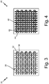
- FIG. 3 is a schematic drawing of 2-D woven impact layer 30 with a high temperature thermoplastic fiber matrix for a floor panel assembly.
- Woven impact layer 30 includes first x-fibers 32, y-fibers 34, and resin 38.
- Weaving patterns may be plain woven, twill, satin, jersey knit, or interlock knit.
- X-fibers 32 and y-fibers 34 are high temperature thermoplastic fibers that have been woven together according to a pattern.
- Fibers 32, 34 can be for example, polyetheretherketone, polyaryletherketones, polycarbonate, polyphenylene sulfide, polyetherimide, polyimide, polymethylmethacrylate (acrylic), polyvinylchloride, polyurethane, polytetrafluoroethylene, or polyamideimide.
- the high temperature thermoplastic material has low smoke release in smoke tests and low flammability.
- Resin 38 is impregnated throughout woven impact layer 30 around x-fibers 32, y-fibers 34, and securing fibers 32, 34, in the weave of impact layer 30.
- Resin 38 can be an epoxy or phenolic resin, added either after weaving of impact layer 30, or during weaving of impact layer 30.
- FIG. 4 is a schematic drawing of 2-D woven impact layer 40 with a composite fiber matrix for a floor panel assembly.
- Woven impact layer 40 includes x-fibers 42, y-fibers 44, and resin 48.
- X-fibers 42, y-fibers 44, and resin 48 are connected in the same manner as their corresponding components in FIG. 3 .
- x-fibers 42 are high temperature thermoplastic fibers, and resin 48 is a phenolic or epoxy resin.
- y-fibers 44 are metallic fibers.
- impact layer 40 is a composite layer.
- x-fibers can be metallic and y-fibers can be a high temperature thermoplastic.
- metallic fibers should be no more than 50% of fibers in the matrix to reduce the weight of impact layer 40.
- the x-fibers and the y-fibers can alternate between a high temperature thermoplastic and a metallic fiber, with the size of the fiber thread dictating the exact percentage of metallic fibers in the woven matrix.
- Metallic y-fibers 44 can be made of metals such as stainless steel, titanium alloys, or nickel alloys. Typically, metallic y-fibers 44 are hard metallic material that would withstand a knife cut. The addition of metallic y-fibers 44 to impact layer 40 increases mechanical strength of impact layer 40 compared to purely high temperature thermoplastic fiber matrices.
- FIG. 5 is a schematic drawing of 3-D woven impact layer 50 with a high temperature thermoplastic fiber matrix for a floor panel assembly.
- Woven impact layer 50 includes x-fibers 52, y-fibers 54, z-fibers 56, and resin 58.
- Impact layer 50 may be stitched or have fibers interwoven in 2 or all three axes.
- a 3-D woven impact layer 50 could include a plurality of impact layers (such as impact layer 40 from FIG. 4 ) stacked together and stitched with z-fibers 56.
- Fibers 52, 54, and 56 are high temperature thermoplastic fibers that have been woven together according to a pattern.
- Fibers 52, 54, 56 can be for example, polyetheretherketone, polyaryletherketones, polycarbonate, polyphenylene sulfide, polyetherimide, polyimide, polymethylmethacrylate (acrylic), polyvinylchloride, polyurethane, polytetrafluoroethylene, or polyamideimide.
- the high temperature thermoplastic material has low smoke release in smoke tests and low flammability.
- Resin 38 is impregnated throughout woven impact layer 50 around x-fibers 52, y-fibers 54, z-fibers 56, and securing fibers 52, 54, 56, in the weave of impact layer 50.
- Resin 58 can be an epoxy or phenolic resin.
- FIG. 6 is a schematic drawing of 3-D woven impact layer 60 with a high temperature thermoplastic fiber matrix for a floor panel assembly.
- Woven impact layer 60 includes x-fibers 62, y-fibers 64, z-fibers 66, and resin 68.
- x-fibers 62 and y-fibers 64 are high temperature thermoplastic fibers, and resin 68 is a phenolic or epoxy resin.
- z-fibers 66 are metallic fibers.
- impact layer 60 is a composite layer.
- x-fibers and/or y-fibers can be metallic and z-fibers can be a high temperature thermoplastic.
- Either a 2:1 high temperature thermoplastic fibers to metallic fibers or a 1:2 high temperature thermoplastic fibers to metallic fibers ratio can be use, depending on the needs of the floor panel assembly.
- Metallic fibers can be used across any of the three direction (x, y, z) as needed. Generally, metallic fibers should be no more than 66% of fibers in the matrix to reduce the weight of impact layer 60.
- Metallic z-fibers 64 can be made of metals such as stainless steel, titanium alloys, or nickel alloys. Typically, metallic z-fibers 64 are hard metallic material that would withstand a knife cut. The addition of metallic z-fibers 64 to impact layer 60 increases mechanical strength of impact layer 40 compared to purely high temperature thermoplastic fiber matrices.
- a woven impact layer containing a high temperature thermoplastic fiber matrix allows for increased mechanical strength of heated floor panel assemblies which meeting flame, smoke, and toxicity requirements.
- high temperature thermoplastic based impact layers are environmentally friendly. High temperature thermoplastics retain the ability to be remolded several times, and can be recycled or reused while still maintaining dimensional integrity and tensile strength.
- a floor panel assembly has a bottom surface and a top surface.
- the floor panel assembly includes a first stack of structural layers adjacent the bottom surface, a core layer adjacent the first stack of structural layers, a second stack of structural layers between the core layer and the top surface, a heating layer between the core layer and the top surface, and a woven impact layer between the heating layer and the top surface.
- the core layer absorbs shear stress.
- the impact layer includes a woven high temperature thermoplastic fiber matrix and a resin infiltrating the woven fiber matrix.
- the assembly of the preceding paragraph can optionally include, additionally and/or alternatively, any one or more of the following features, configurations and/or additional components:
- the woven high temperature thermoplastic fiber matrix comprises woven fibers of polyetheretherketone, polyaryletherketones, polycarbonate, polyphenylene sulfide, polyetherimide, polyimide, polymethylmethacrylate (acrylic), polyvinylchloride, polyurethane, polytetrafluoroethylene, or polyamideimide.
- the high temperature thermoplastic resin has a melting point between melting points between 150 and 400 degrees Celsius.
- the high temperature thermoplastic resin has a tensile strength between 55 MPa and 14 GPa.
- the resin is an an epoxy, phenolic, bismaleimide, or cyanate ester resin.
- the woven impact layer is woven in two dimensions.
- the woven impact layer is woven in three dimensions.
- the woven impact layer further comprises metallic fibers interwoven with the woven high temperature thermoplastic fiber matrix.
- the core layer comprises a high density metallic material in a honeycomb structure.
- the core layer comprises an expanded honeycomb polymer, an open-cell polymer foam, or closed-cell polymer foam.
- the heating layer comprises a metallic material, Positive Temperature Control (PTC) ceramic, PTC polymer, or carbon allotrope material
- the first and second stacks of structural facing layers comprise a reinforced polymer matrix.
- the reinforced polymer matrix comprises a fiber matrix impregnated with a structural resin.
- the fiber matrix is a carbon fiber or fiberglass.
- the structural resin is epoxy, polyurethane, phenolic, cyanate ester, or bismaleimide.
- the heating layer is adjacent the impact layer.
- the heating layer is adjacent the core layer.
- the floor panel assembly includes a second impact layer between the first stack of structural layers and the core layer, and a third stack of structural layers between the first woven impact layer and the second impact layer.
- a method of making a heated floor panel assembly includes aligning a woven impact layer, a heater, a core layer, and one or more structural facing layers and bonding the impact layer, the heater, the core layer, and the one or more structural layers to each other.
- the woven impact layer includes a woven high temperature thermoplastic fiber matrix impregnated with a resin.
Landscapes
- Engineering & Computer Science (AREA)
- Mechanical Engineering (AREA)
- Textile Engineering (AREA)
- Aviation & Aerospace Engineering (AREA)
- Chemical & Material Sciences (AREA)
- Forests & Forestry (AREA)
- Physics & Mathematics (AREA)
- Thermal Sciences (AREA)
- Life Sciences & Earth Sciences (AREA)
- Combustion & Propulsion (AREA)
- General Engineering & Computer Science (AREA)
- Laminated Bodies (AREA)
- Central Heating Systems (AREA)
- Moulding By Coating Moulds (AREA)
- Woven Fabrics (AREA)
- Floor Finish (AREA)
Abstract
Description
- This application relates generally to heated floor panel assemblies for aircraft, and specifically to impact layers for heated floor panel assemblies.
- Heated floor panels are often used in aircraft to mitigate the effects of cold underfloor temperatures and to help maintain a comfortable cabin temperature. The floor panels are typically supported by an aircraft structure arranged, for example, in a grid-like pattern. The floor panels have structural integrity sufficient to support the weight of people and objects resting on the panels. An impact layer typically forms the top surface surface of the panel to protect the underlying layers (e.g. weight supporting layers and/or a heating layer) from punctures from high heels, chips from dropped objects, scratches from dragged luggage, and/or other floor-traffic related hazards.
- Impact Layers can be made with pre-impregnated fabrics where a fiber matrix is impregnated with a resin. Typically, the fiber matrix is made of loose fibers such as fiberglass or carbon fibers, typically impregnated with a phenolic resin or epoxy. To meet flammability, smoke, and toxicity requirements, the resin is usually modified with additives. These modifications result in lower mechanical strength of the impact layer. Thus, an impact layer with a stronger resin-impregnated fiber matrix is needed.
- In one embodiment, a floor panel assembly has a bottom surface and a top surface. The floor panel assembly includes a first stack of structural layers adjacent the bottom surface, a core layer adjacent the first stack of structural layers, a second stack of structural layers between the core layer and the top surface, a heating layer between the core layer and the top surface, and a woven impact layer between the heating layer and the top surface. The core layer absorbs shear stress. The impact layer includes a woven high temperature thermoplastic fiber matrix and a resin infiltrating the woven fiber matrix.
- In a different embodiment, a method of making a heated floor panel assembly includes aligning a woven impact layer, a heater, a core layer, and one or more structural facing layers and bonding the impact layer, the heater, the core layer, and the one or more structural layers to each other. The woven impact layer includes a woven high temperature thermoplastic fiber matrix impregnated with a resin.
-
-
FIG. 1 is a schematic drawings of a heated floor panel assembly. -
FIG. 2 is a schematic drawings of a heated floor panel assembly in a different embodiment. -
FIG. 3 is a schematic drawing of a 2-D woven impact layer with a high temperature thermoplastic fiber matrix for a floor panel assembly. -
FIG. 4 is a schematic drawing of a 2-D woven impact layer with a composite fiber matrix for a floor panel assembly. -
FIG. 5 is a schematic drawing of a 3-D woven impact layer with a high temperature thermoplastic fiber matrix for a floor panel assembly. -
FIG. 6 is a schematic drawing of a 3-D woven impact layer with a high temperature thermoplastic fiber matrix for a floor panel assembly. - The present invention is directed to a composite panel, and more specifically, to a heated floor panel with a woven impact layer containing a woven high temperature thermoplastic fiber matrix, or a woven composite fiber matrix, impregnated with a resin. The panel further includes structural layers and a core layer supporting the assembly, and a heating layer containing a heating element.
-
FIG. 1 is a schematic diagram of heatedfloor panel assembly 10 havingbottom surface 12 andtop surface 14.Assembly 10 contains first stack ofstructural layer 16,core layer 18, second stack ofstructural layers 20,heating layer 22, andimpact layer 24. -
Bottom surface 12 ofassembly 10 is attached to an aircraft, whiletop surface 14 faces the inside of an aircraft cabin or other floor area needing to be heated.Components bottom surface 12 andtop surface 14. First stack ofstructural layers 16 is attached tobottom surface 12.Core layer 18 is attached to first stack ofstructural layers 16opposite bottom surface 12. Second stack ofstructural layers 20 is attached tocore layer 18 opposite first stack ofstructural layers 16.Heating layer 22 is attached to second stack ofstructural layers 20opposite core layer 18.Impact layer 24 is attached toheating layer 22 opposite second stack ofstructural layers 20.Impact layer 24 facestop surface 14. - Stacks of
structural layers assembly 10. Stacks ofstructural layers structural layers -
Core layer 18 provides impact resistance toassembly 10, and carries shear loads to stiffenfloor panel assembly 10.Core layer 18 can, in an exemplary embodiment, be formed from a high density metallic material, such as aluminum alloy, stainless steel, or titanium, and can further be arranged in a honeycomb structure. Alternatively,core layer 18 can be formed from an expanded honeycomb polymer, such as resin-infused aramids (e.g., Kevlar® or Nomex®), resin-infused carbon fiber or fiberglass, thermoplastic tubing, as well as an open-cell or closed-cell polymer foam. Infusing resins could be epoxy, phenolic, or cyanate ester. Generally, a metallic core layer has greater thermal conductivity than a polymer core layer. -
Heating layer 22 can include an electrical heating element (not shown) embedded on or inheating layer 22. The heating element can be a resistive heating element formed, for example, from a metallic material, Positive Temperature Control (PTC) ceramic, PTC polymer, or carbon allotrope material such as a carbon nanotube (CNT) heater. The heating element can be arranged as an etched foil, wire, or printed-ink element. Other suitable heating elements are contemplated herein.Heating layer 22 can be used to control the temperature oftop surface 14 ofassembly 10, which can be installed, for example, in an aircraft cabin or cockpit. In certain embodiments, the heating element can extend across the entire area ofheating layer 22. In other embodiments, the heating element can be inset some distance from the edges ofheating layer 22 in order to protect the element from fluid spills along or damage at the edges ofassembly 10. The heating element is electrically connected to an electrical source via electrodes or wires. -
Impact layer 24 contains both a woven fiber matrix and a resin. The woven fiber matrix ofimpact layer 24 can be made of a high temperature thermoplastic. The resin ofimpact layer 24 is a phenolic, epoxy, polyurethane, bismaleimide, or cyanate ester resin. The fiber strength should be between 55 MPa and 14 GPa. - High temperature thermoplastic (also known as high-performance thermoplastics) have working temperature up to between 150 and 400 degrees Celsius and have significant retention of physical properties, dimensional stability, and electrical characteristics at high temperatures. Thus, high temperature thermoplastics have higher heat deflection temperatures, glass transition temperatures, and continuous use temperature. Additionally, high temperature thermoplastics also offer better chemical resistance than most other polymers. High temperature thermoplastics are known to have enhanced mechanical properties, resistance to damages, and be recyclable.
- As an example, PEEK contains excellent mechanical and chemical resistance during high temperature applications. PEEK has tensile modulus strength of 90-200 MPa, a melting temperature of 343 degrees Celsius, and a density of 1.32 g/cm3. Similarly, PEI offers outstanding elevated thermal resistance, high strength, stiffness and chemical resistance. PEI has a tensile modulus strength between 96-190 MPa, a melting temperature above 217 degrees Celsius, and an amorphous density of 1.27 g/cm3. Similarly, PTFE fibers (such as Gore ® Fibers) can have a tensile strength up to 13 GPa when properly processed, a melting temperature of 340 degrees Celsius, and a density of 2.2 g/cm3.
- The high temperature thermoplastic can be a polyether ether ketone (PEEK), polyaryletherketones (PAEK), polycarbonate (PC), polyphenylene sulfide (PPS), polyetherimide (PEI), polyimide, poly(methyl methacrylate) (PMMA), polyvinyl chloride, polyurethane, polytetrafluoroethylene (PTFE), or polyamideimide. Alternatively, the woven fiber matrix of
impact layer 24 can be a composite matrix including both high temperature thermoplastic fibers and metallic fibers woven together. The fibers can be woven in two dimensions, or woven in three dimensions to create a woven impact layer. - The use of a high temperature thermoplastic resin allows for
assembly 10 to meet more stringent flammability, smoke, and toxicity (FST) requirements due to the toughness of the high temperature thermoplastic resin. The U.S. Federal Aviation Administration (FAA) mandates stringent FST characteristics for aircraft cabin components under 14 C.F.R. 25.853. Generally reported as peak heat release (kilowatts per square meter) and total heat release (kilowatts per minute per square meter), the FAA regulatory peak/total requirement number is 65 kW/m2 peak heat release and 65 kW/m2 total heat release. High temperature thermoplastic resins have low smoke release in smoke tests and low flammability, surpassing these requirements. - High temperature thermoplastics also have high mechanical strength, high level of toughness, strength, stiffness, resistance to fatigue and ductility, sufficiently protecting floor panel assemblies from puncture or damage. Additionally, high temperature thermoplastics show increased resistance to chemicals, solvents, radiation and heat, and do not disintegrate or lose its form upon exposure.
-
FIG. 2 is a schematic drawings of heatedfloor panel assembly 26 in a different embodiment.Assembly 26 has many of the same components asassembly 10 inFIG. 1 , but arranged in a different configuration. - Here, as in
assembly 10,bottom surface 12 ofassembly 10 is anchored to an aircraft, whiletop surface 14 faces the inside of an aircraft cabin or other floor area needing to be heated.Components bottom surface 12 andtop surface 14. First stack ofstructural layers 16 is attached tobottom surface 12.Core layer 18 is attached to first stack ofstructural layers 16opposite bottom surface 12. - However,
heating layer 22 is attached tocore layer 18 opposite first stack ofstructural layers 16. Because of this, second stack ofstructural layers 20 are attached toheating layer 22opposite core layer 18, andimpact layer 24 is attached directly to second stack ofstructural layers 20.Impact layer 24 facestop surface 14. -
FIG. 3 is a schematic drawing of 2-Dwoven impact layer 30 with a high temperature thermoplastic fiber matrix for a floor panel assembly.Woven impact layer 30 includes first x-fibers 32, y-fibers 34, andresin 38. Weaving patterns may be plain woven, twill, satin, jersey knit, or interlock knit. - X-fibers 32 and y-
fibers 34 are high temperature thermoplastic fibers that have been woven together according to a pattern.Fibers - The woven nature of the fiber matrix creates a mechanically sound impact layer.
Resin 38 is impregnated throughout wovenimpact layer 30 around x-fibers 32, y-fibers 34, and securingfibers impact layer 30.Resin 38 can be an epoxy or phenolic resin, added either after weaving ofimpact layer 30, or during weaving ofimpact layer 30. -
FIG. 4 is a schematic drawing of 2-Dwoven impact layer 40 with a composite fiber matrix for a floor panel assembly.Woven impact layer 40 includesx-fibers 42, y-fibers 44, andresin 48. X-fibers 42, y-fibers 44, andresin 48 are connected in the same manner as their corresponding components inFIG. 3 . - Like in
FIG. 3 , x-fibers 42 are high temperature thermoplastic fibers, andresin 48 is a phenolic or epoxy resin. However, y-fibers 44 are metallic fibers. Thus,impact layer 40 is a composite layer. In alternative embodiments, x-fibers can be metallic and y-fibers can be a high temperature thermoplastic. Generally, metallic fibers should be no more than 50% of fibers in the matrix to reduce the weight ofimpact layer 40. Additionally, the x-fibers and the y-fibers can alternate between a high temperature thermoplastic and a metallic fiber, with the size of the fiber thread dictating the exact percentage of metallic fibers in the woven matrix. - Metallic y-
fibers 44 can be made of metals such as stainless steel, titanium alloys, or nickel alloys. Typically, metallic y-fibers 44 are hard metallic material that would withstand a knife cut. The addition of metallic y-fibers 44 toimpact layer 40 increases mechanical strength ofimpact layer 40 compared to purely high temperature thermoplastic fiber matrices. -
FIG. 5 is a schematic drawing of 3-Dwoven impact layer 50 with a high temperature thermoplastic fiber matrix for a floor panel assembly.Woven impact layer 50 includesx-fibers 52, y-fibers 54, z-fibers 56, andresin 58.Impact layer 50 may be stitched or have fibers interwoven in 2 or all three axes. For example, a 3-Dwoven impact layer 50 could include a plurality of impact layers (such asimpact layer 40 fromFIG. 4 ) stacked together and stitched with z-fibers 56. -
Fibers Fibers - After being woven together, they are infiltrated with
resin 58. The woven nature of the fiber matrix creates a mechanically sound impact layer.Resin 38 is impregnated throughout wovenimpact layer 50 around x-fibers 52, y-fibers 54, z-fibers 56, and securingfibers impact layer 50.Resin 58 can be an epoxy or phenolic resin. -
FIG. 6 is a schematic drawing of 3-Dwoven impact layer 60 with a high temperature thermoplastic fiber matrix for a floor panel assembly.Woven impact layer 60 includesx-fibers 62, y-fibers 64, z-fibers 66, andresin 68. - Like
impact layer 50, x-fibers 62 and y-fibers 64 are high temperature thermoplastic fibers, andresin 68 is a phenolic or epoxy resin. However, z-fibers 66 are metallic fibers. Thus,impact layer 60 is a composite layer. In alternative embodiments, x-fibers and/or y-fibers can be metallic and z-fibers can be a high temperature thermoplastic. - Either a 2:1 high temperature thermoplastic fibers to metallic fibers or a 1:2 high temperature thermoplastic fibers to metallic fibers ratio can be use, depending on the needs of the floor panel assembly. Metallic fibers can be used across any of the three direction (x, y, z) as needed. Generally, metallic fibers should be no more than 66% of fibers in the matrix to reduce the weight of
impact layer 60. - Metallic z-
fibers 64 can be made of metals such as stainless steel, titanium alloys, or nickel alloys. Typically, metallic z-fibers 64 are hard metallic material that would withstand a knife cut. The addition of metallic z-fibers 64 toimpact layer 60 increases mechanical strength ofimpact layer 40 compared to purely high temperature thermoplastic fiber matrices. - A woven impact layer containing a high temperature thermoplastic fiber matrix allows for increased mechanical strength of heated floor panel assemblies which meeting flame, smoke, and toxicity requirements. Finally, high temperature thermoplastic based impact layers are environmentally friendly. High temperature thermoplastics retain the ability to be remolded several times, and can be recycled or reused while still maintaining dimensional integrity and tensile strength.
- The following are non-exclusive descriptions of possible embodiments of the present invention.
- A floor panel assembly has a bottom surface and a top surface. The floor panel assembly includes a first stack of structural layers adjacent the bottom surface, a core layer adjacent the first stack of structural layers, a second stack of structural layers between the core layer and the top surface, a heating layer between the core layer and the top surface, and a woven impact layer between the heating layer and the top surface. The core layer absorbs shear stress. The impact layer includes a woven high temperature thermoplastic fiber matrix and a resin infiltrating the woven fiber matrix.
- The assembly of the preceding paragraph can optionally include, additionally and/or alternatively, any one or more of the following features, configurations and/or additional components:
- The woven high temperature thermoplastic fiber matrix comprises woven fibers of polyetheretherketone, polyaryletherketones, polycarbonate, polyphenylene sulfide, polyetherimide, polyimide, polymethylmethacrylate (acrylic), polyvinylchloride, polyurethane, polytetrafluoroethylene, or polyamideimide.
- The high temperature thermoplastic resin has a melting point between melting points between 150 and 400 degrees Celsius.
- The high temperature thermoplastic resin has a tensile strength between 55 MPa and 14 GPa.
- The resin is an an epoxy, phenolic, bismaleimide, or cyanate ester resin.
- The woven impact layer is woven in two dimensions.
- The woven impact layer is woven in three dimensions.
- The woven impact layer further comprises metallic fibers interwoven with the woven high temperature thermoplastic fiber matrix.
- The core layer comprises a high density metallic material in a honeycomb structure.
- The core layer comprises an expanded honeycomb polymer, an open-cell polymer foam, or closed-cell polymer foam.
- The heating layer comprises a metallic material, Positive Temperature Control (PTC) ceramic, PTC polymer, or carbon allotrope material
- The first and second stacks of structural facing layers comprise a reinforced polymer matrix.
- The reinforced polymer matrix comprises a fiber matrix impregnated with a structural resin.
- The fiber matrix is a carbon fiber or fiberglass.
- The structural resin is epoxy, polyurethane, phenolic, cyanate ester, or bismaleimide.
- The heating layer is adjacent the impact layer.
- The heating layer is adjacent the core layer.
- The floor panel assembly includes a second impact layer between the first stack of structural layers and the core layer, and a third stack of structural layers between the first woven impact layer and the second impact layer.
- A method of making a heated floor panel assembly includes aligning a woven impact layer, a heater, a core layer, and one or more structural facing layers and bonding the impact layer, the heater, the core layer, and the one or more structural layers to each other. The woven impact layer includes a woven high temperature thermoplastic fiber matrix impregnated with a resin.
- While the invention has been described with reference to an exemplary embodiment(s), it will be understood by those skilled in the art that various changes may be made and equivalents may be substituted for elements thereof without departing from the scope of the invention. In addition, many modifications may be made to adapt a particular situation or material to the teachings of the invention without departing from the essential scope thereof. Therefore, it is intended that the invention not be limited to the particular embodiment(s) disclosed, but that the invention will include all embodiments falling within the scope of the appended claims.
Claims (15)
- A floor panel assembly (10) having a bottom surface (12) and a top surface (14), the floor panel assembly comprising:a first stack of structural layers (16) adjacent the bottom surface (12);a core layer (18), adjacent the first stack of structural layers (16), that absorbs shear stress;a second stack of structural layers (20) between the core layer (18) and the top surface (14);a heating layer (22) between the core layer (18) and the top surface (14); anda woven impact layer (24) between the heating layer (22) and the top surface (14), the impact layer (24) comprising:a woven high temperature thermoplastic fiber matrix; anda resin infiltrating the woven fiber matrix.
- The floor panel assembly (10) of claim 1, wherein the woven high temperature thermoplastic fiber matrix comprises woven fibers of polyetheretherketone, polyaryletherketones, polycarbonate, polyphenylene sulfide, polyetherimide, polyimide, polymethylmethacrylate (acrylic), polyvinylchloride, polyurethane, polytetrafluoroethylene, or polyamideimide; and the high temperature thermoplastic fiber matrix has a melting point between melting points between 150 and 400 degrees Celsius and a tensile strength between 55 MPa and 14 GPa.
- The floor panel assembly (10) of claim 1 or 2, wherein the resin is an epoxy, phenolic, bismaleimide, or cyanate ester resin.
- The floor panel assembly (10) of claim 1, 2, or 3, wherein the woven impact layer (24) is woven in two dimensions.
- The floor panel assembly of claim 1, 2, or 3, wherein the woven impact layer (24) is woven in three dimensions.
- The floor panel assembly of any preceding claim, wherein the woven impact layer (24) further comprises metallic fibers interwoven with the woven high temperature thermoplastic fiber matrix.
- The floor panel assembly of any preceding claim, wherein the core layer (18) comprises a high density metallic material in a honeycomb structure.
- The floor panel assembly of claim 1, 2, 3, 4, 5, or 6, wherein the core layer (18) comprises an expanded honeycomb polymer, an open-cell polymer foam, or closed-cell polymer foam.
- The floor panel assembly of any preceding claim, wherein the heating layer (22) comprises a metallic material, Positive Temperature Control (PTC) ceramic, PTC polymer, or carbon allotrope material.
- The floor panel assembly of any preceding claim, wherein the first and second stacks of structural facing layers comprise a reinforced polymer matrix.
- The floor panel assembly of claim 10, where in the reinforced polymer matrix comprises a fiber matrix impregnated with a structural resin, wherein the fiber matrix is a carbon fiber or fiberglass and the structural resin is epoxy, polyurethane, phenolic, cyanate ester, or bismaleimide.
- The floor panel assembly of any preceding claim, wherein the heating layer (22) is adjacent the impact layer (24).
- The floor panel assembly of claim 1, 2, 3, 4, 5, 6, 7, 8, 9, 10, or 11 wherein the heating layer (22) is adjacent the core layer (18).
- The floor panel assembly (10) of any preceding claim, further comprising:a second impact layer between the first stack of structural layers and the core layer; anda third stack of structural layers between the first woven impact layer and the second impact layer.
- A method of making a heated floor panel assembly (10) comprising:aligning a woven impact layer (24), a heater, a core layer (18), and one or more structural facing layers (16), wherein the woven impact layer (24) comprises a woven high temperature thermoplastic fiber matrix impregnated with a resin;bonding the impact layer (24), the heater, the core layer (18), and the one or more structural layers to each other.
Applications Claiming Priority (1)
| Application Number | Priority Date | Filing Date | Title |
|---|---|---|---|
| US201862693752P | 2018-07-03 | 2018-07-03 |
Publications (2)
| Publication Number | Publication Date |
|---|---|
| EP3590699A1 true EP3590699A1 (en) | 2020-01-08 |
| EP3590699B1 EP3590699B1 (en) | 2021-12-01 |
Family
ID=67314579
Family Applications (1)
| Application Number | Title | Priority Date | Filing Date |
|---|---|---|---|
| EP19182513.2A Active EP3590699B1 (en) | 2018-07-03 | 2019-06-26 | Impact and knife cut resistant pre-impregnated woven fabric for aircraft heated floor panels |
Country Status (6)
| Country | Link |
|---|---|
| US (2) | US11376811B2 (en) |
| EP (1) | EP3590699B1 (en) |
| JP (1) | JP7232565B2 (en) |
| BR (1) | BR102019012653A2 (en) |
| CA (1) | CA3048438A1 (en) |
| ES (1) | ES2900067T3 (en) |
Cited By (2)
| Publication number | Priority date | Publication date | Assignee | Title |
|---|---|---|---|---|
| IT202000016228A1 (en) * | 2020-07-06 | 2022-01-06 | Tecnologie Avanzate S R L | UNDERFLOOR HEATING SYSTEM FOR PASSENGER TRAINS |
| AU2020446821B2 (en) * | 2019-10-15 | 2024-12-12 | Zhongjiang LONG | Polyurethane composite floor and fabrication process therefor |
Families Citing this family (7)
| Publication number | Priority date | Publication date | Assignee | Title |
|---|---|---|---|---|
| US11376811B2 (en) | 2018-07-03 | 2022-07-05 | Goodrich Corporation | Impact and knife cut resistant pre-impregnated woven fabric for aircraft heated floor panels |
| DE102018009218B4 (en) * | 2018-11-23 | 2025-04-10 | Airbus Operations Gmbh | Cladding element with heating layer in sandwich construction |
| KR102109019B1 (en) * | 2019-12-26 | 2020-05-12 | 이성만 | Heating fabric |
| US11827079B2 (en) * | 2020-10-14 | 2023-11-28 | GM Global Technology Operations LLC | Class a surface radiant heating system |
| US20240246103A1 (en) * | 2023-01-25 | 2024-07-25 | Instant Auto Body Inc. | All season portable paint booth |
| US12291014B2 (en) | 2023-08-21 | 2025-05-06 | B/E Aerospace (Uk) Limited | Mineral additive modified basalt fibre based PMMA composites for ballistic applications |
| CN118528612B (en) * | 2024-05-15 | 2025-03-21 | 比亚迪股份有限公司 | Fiber composite material and preparation method thereof, protective structural component and vehicle |
Citations (2)
| Publication number | Priority date | Publication date | Assignee | Title |
|---|---|---|---|---|
| WO2012087294A1 (en) * | 2010-12-21 | 2012-06-28 | Milwaukee Composites, Inc. | Panel with heated layer |
| EP3095690A2 (en) * | 2015-05-21 | 2016-11-23 | Goodrich Corporation | Aircraft floor panel |
Family Cites Families (89)
| Publication number | Priority date | Publication date | Assignee | Title |
|---|---|---|---|---|
| US949389A (en) | 1909-11-15 | 1910-02-15 | Anna Lisa Almgren | Crib attachment. |
| US3584198A (en) | 1968-02-29 | 1971-06-08 | Matsushita Electric Works Ltd | Flexible electric surface heater |
| GB1444718A (en) | 1972-11-16 | 1976-08-04 | Atkinson Electrical Eng Co Ltd | Electrical heating unit |
| JPH0279593U (en) | 1988-12-06 | 1990-06-19 | ||
| US5175198A (en) | 1991-08-30 | 1992-12-29 | General Electric Company | Thermoformable/polycarbonate/woven glass cloth composites |
| JP2715393B2 (en) * | 1991-10-15 | 1998-02-18 | ソマール株式会社 | Manufacturing method of valve plate for reed valve |
| US5451747A (en) | 1992-03-03 | 1995-09-19 | Sunbeam Corporation | Flexible self-regulating heating pad combination and associated method |
| JPH0732518A (en) | 1993-07-16 | 1995-02-03 | Dairin Shoji:Kk | Composite building material |
| US5547735A (en) | 1994-10-26 | 1996-08-20 | Structural Laminates Company | Impact resistant laminate |
| GB9504372D0 (en) | 1995-03-04 | 1995-04-26 | British Aerospace | A composite laminate |
| US6429157B1 (en) | 1997-07-11 | 2002-08-06 | Toray Industries, Inc. | Prepreg fabric and honeycomb sandwich panel |
| US6611659B2 (en) | 1999-04-24 | 2003-08-26 | Airbus Deutschland Gmbh | Electrically heated aircraft composite floor panel |
| US6834159B1 (en) | 1999-09-10 | 2004-12-21 | Goodrich Corporation | Aircraft heated floor panel |
| DE60033425D1 (en) | 1999-12-10 | 2007-03-29 | Thermion Systems Int | MULTILAYER THERMOPLASTIC WOVEN HEATING AND METHOD FOR THE PRODUCTION THEREOF |
| KR100373520B1 (en) | 2000-07-19 | 2003-02-25 | 비멕 주식회사 | Stainless panel and it's manufacture method |
| US6519835B1 (en) | 2000-08-18 | 2003-02-18 | Watlow Polymer Technologies | Method of formable thermoplastic laminate heated element assembly |
| US6315007B1 (en) * | 2001-03-23 | 2001-11-13 | 3Tex, Inc. | High speed three-dimensional weaving method and machine |
| US7087296B2 (en) | 2001-11-29 | 2006-08-08 | Saint-Gobain Technical Fabrics Canada, Ltd. | Energy absorbent laminate |
| US6825137B2 (en) | 2001-12-19 | 2004-11-30 | Telair International Incorporated | Lightweight ballistic resistant rigid structural panel |
| KR100838919B1 (en) | 2002-06-19 | 2008-06-16 | 마츠시타 덴끼 산교 가부시키가이샤 | Flexible PCB Heating Element and Manufacturing Method Thereof |
| US20050042416A1 (en) * | 2003-08-21 | 2005-02-24 | Blackmon James B. | Insulation system having vacuum encased honeycomb offset panels |
| US7247822B2 (en) | 2004-02-05 | 2007-07-24 | Methode Electronics, Inc. | Carbon fiber heating element assembly and methods for making |
| US8070994B2 (en) | 2004-06-18 | 2011-12-06 | Zephyros, Inc. | Panel structure |
| CN100386829C (en) | 2004-07-28 | 2008-05-07 | 王克政 | PTC thick film circuit controllable heating element |
| NL1027053C2 (en) | 2004-09-16 | 2006-03-20 | Robert Oosterling | Rollable floor heating. |
| US20060138279A1 (en) | 2004-12-23 | 2006-06-29 | Nathan Pisarski | Aircraft floor panel |
| DE202005000886U1 (en) | 2005-01-19 | 2006-06-29 | Kronospan Technical Co. Ltd., Engomi | Heating device for wall, ceiling or floor coverings |
| US8360362B2 (en) | 2006-02-21 | 2013-01-29 | The Boeing Company | Aircraft floor and method of assembly |
| JP2009523083A (en) | 2006-09-06 | 2009-06-18 | ポリストランド インコーポレイティッド | Composite laminate and its manufacturing method |
| US20080081528A1 (en) * | 2006-09-29 | 2008-04-03 | Carter H Landis | High impact strength, fire resistant woven article |
| US9161393B2 (en) | 2006-10-04 | 2015-10-13 | T+Ink, Inc. | Heated textiles and methods of making the same |
| US20080166563A1 (en) | 2007-01-04 | 2008-07-10 | Goodrich Corporation | Electrothermal heater made from thermally conducting electrically insulating polymer material |
| US20090011210A1 (en) | 2007-02-15 | 2009-01-08 | Xiao Gao | Lightweight glass fiber reinforced thermoplastic material |
| US8283602B2 (en) | 2007-03-19 | 2012-10-09 | Augustine Temperature Management LLC | Heating blanket |
| GB2453769B (en) | 2007-10-18 | 2012-09-05 | Gkn Aerospace Services Ltd | An aircraft leading edge thermoplastic heating mat |
| WO2009117408A1 (en) | 2008-03-18 | 2009-09-24 | Watlow Electric Manufacturing Company | Layered heater system with honeycomb core structure |
| US20100065686A1 (en) | 2008-04-28 | 2010-03-18 | Tauscher Kurt M | Aircraft heated floor panel |
| US8286919B2 (en) | 2008-05-13 | 2012-10-16 | The Boeing Company | Impact resistant composite structures |
| US20100021718A1 (en) | 2008-07-23 | 2010-01-28 | Sandra Fritz Vos | Thermoplastic composite material with improved smoke generation, heat release, and mechanical properties |
| JP4862913B2 (en) | 2009-03-31 | 2012-01-25 | 東レ株式会社 | Prepregs and preforms |
| US8613406B2 (en) | 2008-09-02 | 2013-12-24 | Interface, Inc. | Methods for installing carpet tiles on the floor of a vehicle |
| US8158245B2 (en) | 2009-09-24 | 2012-04-17 | Cytec Technology Corp. | Thermoplastic composites and methods of making and using same |
| EP2491758A1 (en) | 2009-10-22 | 2012-08-29 | Datec Coating Corporation | Method of melt bonding high-temperature thermoplastic based heating element to a substrate |
| CN102056353A (en) | 2009-11-10 | 2011-05-11 | 清华大学 | Heating device and manufacturing method thereof |
| US20120234819A1 (en) | 2009-11-13 | 2012-09-20 | Berger Craig M | Multilayer structural heating panel |
| DE112011101808T5 (en) | 2010-05-27 | 2013-05-16 | W.E.T.Automotive Systems Ltd. | Heating device for a motor vehicle and method for its production |
| EP2463083B1 (en) | 2010-12-13 | 2016-06-29 | The Boeing Company | Green aircraft interior panels and method of fabrication |
| FR2974754B1 (en) | 2011-05-02 | 2013-06-28 | Daher Aerospace | SELF-REINFORCED COMPOSITE PANEL, IN PARTICULAR FOR AIRCRAFT FLOORS, AND METHOD OF MANUFACTURING SUCH A PANEL |
| LU91913B1 (en) | 2011-12-15 | 2013-06-17 | Iee Sarl | Sheet-type ohmic heating element |
| KR101201053B1 (en) | 2012-04-16 | 2012-11-14 | 김선일 | Planar heating element |
| CA2813551C (en) | 2012-04-20 | 2018-10-30 | Goodrich Corporation | Printed heating element |
| WO2014024165A2 (en) | 2012-08-08 | 2014-02-13 | Centi - Centro De Nanotecnologia E Materiais Técnicos Funcionais E Inteligentes | Heating device, respective printing and using methods |
| US9388515B2 (en) * | 2012-09-28 | 2016-07-12 | Saprex, Llc | Heat curable composite textile |
| EP2914395B1 (en) | 2012-11-05 | 2019-02-27 | PolyOne Corporation | High strength, light weight composite structure, method of manufacture and use thereof |
| US9253823B2 (en) | 2013-02-10 | 2016-02-02 | The Boeing Company | Metal matrix composite used as a heating element |
| US9493894B2 (en) | 2013-06-12 | 2016-11-15 | Spectra Aerostructures of South Carolina, Inc. | Interior panel for vehicle |
| GB2517465A (en) | 2013-08-21 | 2015-02-25 | Airbus Operations Ltd | Panel for an aircraft |
| US9623951B2 (en) | 2013-08-21 | 2017-04-18 | Goodrich Corporation | Heating elements for aircraft heated floor panels |
| US9427940B2 (en) | 2013-11-12 | 2016-08-30 | Sikorsky Aircraft Corporation | Impact resistant composite panel and method of forming a composite panel |
| US10391734B2 (en) | 2014-02-27 | 2019-08-27 | B/E Aerospace, Inc. | Composite sandwich panel with differential resin layers |
| US10373745B2 (en) | 2014-06-12 | 2019-08-06 | LMS Consulting Group | Electrically conductive PTC ink with double switching temperatures and applications thereof in flexible double-switching heaters |
| US11302463B2 (en) | 2014-06-12 | 2022-04-12 | Lms Consulting Group, Llc | Electrically conductive PTC ink with double switching temperatures and applications thereof in flexible double-switching heaters |
| KR101602880B1 (en) | 2014-06-18 | 2016-03-11 | (주)유니플라텍 | Positive temperature coefficient using conductive liquid emulsion polymer composition, manufacturing method of thereoff, Face heater with it |
| US10440829B2 (en) | 2014-07-03 | 2019-10-08 | United Technologies Corporation | Heating circuit assembly and method of manufacture |
| US9855721B2 (en) | 2014-09-25 | 2018-01-02 | The Boeing Company | Nonwoven decorative laminates and methods of making the same |
| US10632718B2 (en) * | 2014-09-30 | 2020-04-28 | The Boeing Company | Filament network for a composite structure |
| EP3015360B1 (en) | 2014-10-29 | 2019-05-29 | Airbus Operations GmbH | A floor panel for an aircraft, and an aircraft comprising such a floor panel |
| JP2016088264A (en) | 2014-11-04 | 2016-05-23 | トヨタ自動車株式会社 | Vehicle structure |
| FR3033573B1 (en) | 2015-03-10 | 2018-03-23 | Arkema France | THERMOPLASTIC COMPOSITION AND PRE-IMPREGNE, COMPOSITE MATERIAL BASED ON SAID PRE-IMPREGN AND USES OF SAID COMPOSITE MATERIAL |
| US9736888B2 (en) | 2015-03-12 | 2017-08-15 | The Boeing Company | Composite panel with integrated heater and associated methods for manufacturing |
| DE102015105603B4 (en) | 2015-04-13 | 2017-02-09 | Airbus Operations Gmbh | Sandwich panel for an aircraft |
| EP3086011B1 (en) | 2015-04-21 | 2019-07-31 | Airbus Operations GmbH | Double-walled pipe with integrated heating capability for an aircraft or spacecraft |
| US9668301B2 (en) | 2015-07-03 | 2017-05-30 | Ndt Engineering & Aerospace Co., Ltd. | Wet-use plane heater using PTC constant heater-ink polymer |
| US20170238369A1 (en) | 2016-02-12 | 2017-08-17 | Goodrich Corporation | Heated aircraft floor panels |
| FR3048151B1 (en) | 2016-02-19 | 2018-02-23 | Gerflor | MULTILAYER STRUCTURE FOR REALIZING A FLOORING OF A FLOOR OR A HEATING WALL |
| EP3216690B1 (en) | 2016-03-07 | 2018-11-07 | Airbus Operations GmbH | Method for manufacturing a lining panel |
| DE102016107908A1 (en) | 2016-04-28 | 2017-11-02 | Jenoptik Advanced Systems Gmbh | Heating device and method for producing the same |
| KR20170140587A (en) * | 2016-06-13 | 2017-12-21 | 주식회사 휴비스 | Multilayer Composite Agent Stitched With Reinforcing Fibers And The Process For Producing The Same |
| US11297692B2 (en) | 2016-11-01 | 2022-04-05 | Goodrich Corporation | Multilayered panels |
| EP3318481B1 (en) | 2016-11-04 | 2020-07-08 | Airbus Operations, S.L. | Panel structure for an aircraft and manufacturing method thereof |
| US10425989B2 (en) | 2016-12-20 | 2019-09-24 | Goodrich Corporation | Heated floor panels with thermally conductive and electrically insulating fabric |
| US11040765B2 (en) | 2018-06-27 | 2021-06-22 | Goodrich Corporation | Advanced composite heated floor panel |
| US11376811B2 (en) | 2018-07-03 | 2022-07-05 | Goodrich Corporation | Impact and knife cut resistant pre-impregnated woven fabric for aircraft heated floor panels |
| US11273897B2 (en) | 2018-07-03 | 2022-03-15 | Goodrich Corporation | Asymmetric surface layer for floor panels |
| US10899427B2 (en) | 2018-07-03 | 2021-01-26 | Goodrich Corporation | Heated floor panel with impact layer |
| US20200015325A1 (en) | 2018-07-03 | 2020-01-09 | Goodrich Corporation | Fusion welded positive temperature coefficient heater assemblies |
| US10920994B2 (en) | 2018-07-03 | 2021-02-16 | Goodrich Corporation | Heated floor panels |
| US10875623B2 (en) | 2018-07-03 | 2020-12-29 | Goodrich Corporation | High temperature thermoplastic pre-impregnated structure for aircraft heated floor panel |
| US11499724B2 (en) | 2018-07-03 | 2022-11-15 | Goodrich Corporation | Heated floor panels |
-
2019
- 2019-05-14 US US16/411,561 patent/US11376811B2/en active Active
- 2019-06-18 BR BR102019012653A patent/BR102019012653A2/en not_active Application Discontinuation
- 2019-06-20 JP JP2019114176A patent/JP7232565B2/en active Active
- 2019-06-26 EP EP19182513.2A patent/EP3590699B1/en active Active
- 2019-06-26 ES ES19182513T patent/ES2900067T3/en active Active
- 2019-07-02 CA CA3048438A patent/CA3048438A1/en active Pending
-
2022
- 2022-05-27 US US17/804,436 patent/US11878500B2/en active Active
Patent Citations (2)
| Publication number | Priority date | Publication date | Assignee | Title |
|---|---|---|---|---|
| WO2012087294A1 (en) * | 2010-12-21 | 2012-06-28 | Milwaukee Composites, Inc. | Panel with heated layer |
| EP3095690A2 (en) * | 2015-05-21 | 2016-11-23 | Goodrich Corporation | Aircraft floor panel |
Cited By (3)
| Publication number | Priority date | Publication date | Assignee | Title |
|---|---|---|---|---|
| AU2020446821B2 (en) * | 2019-10-15 | 2024-12-12 | Zhongjiang LONG | Polyurethane composite floor and fabrication process therefor |
| IT202000016228A1 (en) * | 2020-07-06 | 2022-01-06 | Tecnologie Avanzate S R L | UNDERFLOOR HEATING SYSTEM FOR PASSENGER TRAINS |
| WO2022009027A1 (en) * | 2020-07-06 | 2022-01-13 | Tecnologie Avanzate S.R.L. | Floor heating system for passenger trains |
Also Published As
| Publication number | Publication date |
|---|---|
| JP7232565B2 (en) | 2023-03-03 |
| ES2900067T3 (en) | 2022-03-15 |
| EP3590699B1 (en) | 2021-12-01 |
| US20200009825A1 (en) | 2020-01-09 |
| US11878500B2 (en) | 2024-01-23 |
| US11376811B2 (en) | 2022-07-05 |
| CA3048438A1 (en) | 2020-01-03 |
| JP2020006943A (en) | 2020-01-16 |
| US20220288887A1 (en) | 2022-09-15 |
| BR102019012653A2 (en) | 2020-01-21 |
Similar Documents
| Publication | Publication Date | Title |
|---|---|---|
| US11878500B2 (en) | Impact and knife cut resistant pre-impregnated woven fabric for aircraft heated floor panels | |
| EP3590702B1 (en) | Heated floor panel with impact layer | |
| EP3590701B1 (en) | High temperature thermoplastic pre-impregnated structure for aircraft heated floor panel | |
| EP3587097B1 (en) | Advanced composite heated floor panel | |
| GB2423224A (en) | Heated floor panel for aircraft | |
| EP3476586B1 (en) | Method for reinforcing a composite sandwich panel | |
| Liu et al. | Effect of woven structure and aramid binder yarn on the flexural performance of carbon/aramid fiber hybrid three‐dimensional woven composites | |
| EP3592107B1 (en) | Heated floor panels | |
| EP3592106B1 (en) | Heated floor panels | |
| KR20230131473A (en) | Composites and Structures | |
| JPWO2017222024A1 (en) | Sheet | |
| Hiremath et al. | Enhancing the effectiveness of laminated kevlar fiber structures against sharp impact |
Legal Events
| Date | Code | Title | Description |
|---|---|---|---|
| PUAI | Public reference made under article 153(3) epc to a published international application that has entered the european phase |
Free format text: ORIGINAL CODE: 0009012 |
|
| STAA | Information on the status of an ep patent application or granted ep patent |
Free format text: STATUS: THE APPLICATION HAS BEEN PUBLISHED |
|
| AK | Designated contracting states |
Kind code of ref document: A1 Designated state(s): AL AT BE BG CH CY CZ DE DK EE ES FI FR GB GR HR HU IE IS IT LI LT LU LV MC MK MT NL NO PL PT RO RS SE SI SK SM TR |
|
| AX | Request for extension of the european patent |
Extension state: BA ME |
|
| STAA | Information on the status of an ep patent application or granted ep patent |
Free format text: STATUS: REQUEST FOR EXAMINATION WAS MADE |
|
| STAA | Information on the status of an ep patent application or granted ep patent |
Free format text: STATUS: EXAMINATION IS IN PROGRESS |
|
| 17P | Request for examination filed |
Effective date: 20200707 |
|
| RBV | Designated contracting states (corrected) |
Designated state(s): AL AT BE BG CH CY CZ DE DK EE ES FI FR GB GR HR HU IE IS IT LI LT LU LV MC MK MT NL NO PL PT RO RS SE SI SK SM TR |
|
| 17Q | First examination report despatched |
Effective date: 20200810 |
|
| GRAP | Despatch of communication of intention to grant a patent |
Free format text: ORIGINAL CODE: EPIDOSNIGR1 |
|
| STAA | Information on the status of an ep patent application or granted ep patent |
Free format text: STATUS: GRANT OF PATENT IS INTENDED |
|
| INTG | Intention to grant announced |
Effective date: 20210705 |
|
| GRAS | Grant fee paid |
Free format text: ORIGINAL CODE: EPIDOSNIGR3 |
|
| GRAA | (expected) grant |
Free format text: ORIGINAL CODE: 0009210 |
|
| STAA | Information on the status of an ep patent application or granted ep patent |
Free format text: STATUS: THE PATENT HAS BEEN GRANTED |
|
| AK | Designated contracting states |
Kind code of ref document: B1 Designated state(s): AL AT BE BG CH CY CZ DE DK EE ES FI FR GB GR HR HU IE IS IT LI LT LU LV MC MK MT NL NO PL PT RO RS SE SI SK SM TR |
|
| REG | Reference to a national code |
Ref country code: GB Ref legal event code: FG4D |
|
| REG | Reference to a national code |
Ref country code: AT Ref legal event code: REF Ref document number: 1451366 Country of ref document: AT Kind code of ref document: T Effective date: 20211215 Ref country code: CH Ref legal event code: EP |
|
| REG | Reference to a national code |
Ref country code: IE Ref legal event code: FG4D |
|
| REG | Reference to a national code |
Ref country code: DE Ref legal event code: R096 Ref document number: 602019009644 Country of ref document: DE |
|
| REG | Reference to a national code |
Ref country code: ES Ref legal event code: FG2A Ref document number: 2900067 Country of ref document: ES Kind code of ref document: T3 Effective date: 20220315 |
|
| REG | Reference to a national code |
Ref country code: LT Ref legal event code: MG9D |
|
| REG | Reference to a national code |
Ref country code: NL Ref legal event code: MP Effective date: 20211201 |
|
| REG | Reference to a national code |
Ref country code: AT Ref legal event code: MK05 Ref document number: 1451366 Country of ref document: AT Kind code of ref document: T Effective date: 20211201 |
|
| PG25 | Lapsed in a contracting state [announced via postgrant information from national office to epo] |
Ref country code: RS Free format text: LAPSE BECAUSE OF FAILURE TO SUBMIT A TRANSLATION OF THE DESCRIPTION OR TO PAY THE FEE WITHIN THE PRESCRIBED TIME-LIMIT Effective date: 20211201 Ref country code: LT Free format text: LAPSE BECAUSE OF FAILURE TO SUBMIT A TRANSLATION OF THE DESCRIPTION OR TO PAY THE FEE WITHIN THE PRESCRIBED TIME-LIMIT Effective date: 20211201 Ref country code: FI Free format text: LAPSE BECAUSE OF FAILURE TO SUBMIT A TRANSLATION OF THE DESCRIPTION OR TO PAY THE FEE WITHIN THE PRESCRIBED TIME-LIMIT Effective date: 20211201 Ref country code: BG Free format text: LAPSE BECAUSE OF FAILURE TO SUBMIT A TRANSLATION OF THE DESCRIPTION OR TO PAY THE FEE WITHIN THE PRESCRIBED TIME-LIMIT Effective date: 20220301 Ref country code: AT Free format text: LAPSE BECAUSE OF FAILURE TO SUBMIT A TRANSLATION OF THE DESCRIPTION OR TO PAY THE FEE WITHIN THE PRESCRIBED TIME-LIMIT Effective date: 20211201 |
|
| PG25 | Lapsed in a contracting state [announced via postgrant information from national office to epo] |
Ref country code: SE Free format text: LAPSE BECAUSE OF FAILURE TO SUBMIT A TRANSLATION OF THE DESCRIPTION OR TO PAY THE FEE WITHIN THE PRESCRIBED TIME-LIMIT Effective date: 20211201 Ref country code: PL Free format text: LAPSE BECAUSE OF FAILURE TO SUBMIT A TRANSLATION OF THE DESCRIPTION OR TO PAY THE FEE WITHIN THE PRESCRIBED TIME-LIMIT Effective date: 20211201 Ref country code: NO Free format text: LAPSE BECAUSE OF FAILURE TO SUBMIT A TRANSLATION OF THE DESCRIPTION OR TO PAY THE FEE WITHIN THE PRESCRIBED TIME-LIMIT Effective date: 20220301 Ref country code: LV Free format text: LAPSE BECAUSE OF FAILURE TO SUBMIT A TRANSLATION OF THE DESCRIPTION OR TO PAY THE FEE WITHIN THE PRESCRIBED TIME-LIMIT Effective date: 20211201 Ref country code: HR Free format text: LAPSE BECAUSE OF FAILURE TO SUBMIT A TRANSLATION OF THE DESCRIPTION OR TO PAY THE FEE WITHIN THE PRESCRIBED TIME-LIMIT Effective date: 20211201 Ref country code: GR Free format text: LAPSE BECAUSE OF FAILURE TO SUBMIT A TRANSLATION OF THE DESCRIPTION OR TO PAY THE FEE WITHIN THE PRESCRIBED TIME-LIMIT Effective date: 20220302 |
|
| PG25 | Lapsed in a contracting state [announced via postgrant information from national office to epo] |
Ref country code: NL Free format text: LAPSE BECAUSE OF FAILURE TO SUBMIT A TRANSLATION OF THE DESCRIPTION OR TO PAY THE FEE WITHIN THE PRESCRIBED TIME-LIMIT Effective date: 20211201 |
|
| PG25 | Lapsed in a contracting state [announced via postgrant information from national office to epo] |
Ref country code: SM Free format text: LAPSE BECAUSE OF FAILURE TO SUBMIT A TRANSLATION OF THE DESCRIPTION OR TO PAY THE FEE WITHIN THE PRESCRIBED TIME-LIMIT Effective date: 20211201 Ref country code: SK Free format text: LAPSE BECAUSE OF FAILURE TO SUBMIT A TRANSLATION OF THE DESCRIPTION OR TO PAY THE FEE WITHIN THE PRESCRIBED TIME-LIMIT Effective date: 20211201 Ref country code: RO Free format text: LAPSE BECAUSE OF FAILURE TO SUBMIT A TRANSLATION OF THE DESCRIPTION OR TO PAY THE FEE WITHIN THE PRESCRIBED TIME-LIMIT Effective date: 20211201 Ref country code: PT Free format text: LAPSE BECAUSE OF FAILURE TO SUBMIT A TRANSLATION OF THE DESCRIPTION OR TO PAY THE FEE WITHIN THE PRESCRIBED TIME-LIMIT Effective date: 20220401 Ref country code: EE Free format text: LAPSE BECAUSE OF FAILURE TO SUBMIT A TRANSLATION OF THE DESCRIPTION OR TO PAY THE FEE WITHIN THE PRESCRIBED TIME-LIMIT Effective date: 20211201 Ref country code: CZ Free format text: LAPSE BECAUSE OF FAILURE TO SUBMIT A TRANSLATION OF THE DESCRIPTION OR TO PAY THE FEE WITHIN THE PRESCRIBED TIME-LIMIT Effective date: 20211201 |
|
| REG | Reference to a national code |
Ref country code: DE Ref legal event code: R097 Ref document number: 602019009644 Country of ref document: DE |
|
| PG25 | Lapsed in a contracting state [announced via postgrant information from national office to epo] |
Ref country code: IS Free format text: LAPSE BECAUSE OF FAILURE TO SUBMIT A TRANSLATION OF THE DESCRIPTION OR TO PAY THE FEE WITHIN THE PRESCRIBED TIME-LIMIT Effective date: 20220401 |
|
| PLBE | No opposition filed within time limit |
Free format text: ORIGINAL CODE: 0009261 |
|
| STAA | Information on the status of an ep patent application or granted ep patent |
Free format text: STATUS: NO OPPOSITION FILED WITHIN TIME LIMIT |
|
| PG25 | Lapsed in a contracting state [announced via postgrant information from national office to epo] |
Ref country code: DK Free format text: LAPSE BECAUSE OF FAILURE TO SUBMIT A TRANSLATION OF THE DESCRIPTION OR TO PAY THE FEE WITHIN THE PRESCRIBED TIME-LIMIT Effective date: 20211201 Ref country code: AL Free format text: LAPSE BECAUSE OF FAILURE TO SUBMIT A TRANSLATION OF THE DESCRIPTION OR TO PAY THE FEE WITHIN THE PRESCRIBED TIME-LIMIT Effective date: 20211201 |
|
| 26N | No opposition filed |
Effective date: 20220902 |
|
| PG25 | Lapsed in a contracting state [announced via postgrant information from national office to epo] |
Ref country code: SI Free format text: LAPSE BECAUSE OF FAILURE TO SUBMIT A TRANSLATION OF THE DESCRIPTION OR TO PAY THE FEE WITHIN THE PRESCRIBED TIME-LIMIT Effective date: 20211201 |
|
| PG25 | Lapsed in a contracting state [announced via postgrant information from national office to epo] |
Ref country code: MC Free format text: LAPSE BECAUSE OF FAILURE TO SUBMIT A TRANSLATION OF THE DESCRIPTION OR TO PAY THE FEE WITHIN THE PRESCRIBED TIME-LIMIT Effective date: 20211201 |
|
| REG | Reference to a national code |
Ref country code: CH Ref legal event code: PL |
|
| REG | Reference to a national code |
Ref country code: BE Ref legal event code: MM Effective date: 20220630 |
|
| PG25 | Lapsed in a contracting state [announced via postgrant information from national office to epo] |
Ref country code: LU Free format text: LAPSE BECAUSE OF NON-PAYMENT OF DUE FEES Effective date: 20220626 Ref country code: LI Free format text: LAPSE BECAUSE OF NON-PAYMENT OF DUE FEES Effective date: 20220630 Ref country code: IE Free format text: LAPSE BECAUSE OF NON-PAYMENT OF DUE FEES Effective date: 20220626 Ref country code: CH Free format text: LAPSE BECAUSE OF NON-PAYMENT OF DUE FEES Effective date: 20220630 |
|
| PG25 | Lapsed in a contracting state [announced via postgrant information from national office to epo] |
Ref country code: IT Free format text: LAPSE BECAUSE OF FAILURE TO SUBMIT A TRANSLATION OF THE DESCRIPTION OR TO PAY THE FEE WITHIN THE PRESCRIBED TIME-LIMIT Effective date: 20211201 Ref country code: BE Free format text: LAPSE BECAUSE OF NON-PAYMENT OF DUE FEES Effective date: 20220630 |
|
| P01 | Opt-out of the competence of the unified patent court (upc) registered |
Effective date: 20230521 |
|
| PG25 | Lapsed in a contracting state [announced via postgrant information from national office to epo] |
Ref country code: MK Free format text: LAPSE BECAUSE OF FAILURE TO SUBMIT A TRANSLATION OF THE DESCRIPTION OR TO PAY THE FEE WITHIN THE PRESCRIBED TIME-LIMIT Effective date: 20211201 Ref country code: CY Free format text: LAPSE BECAUSE OF FAILURE TO SUBMIT A TRANSLATION OF THE DESCRIPTION OR TO PAY THE FEE WITHIN THE PRESCRIBED TIME-LIMIT Effective date: 20211201 |
|
| PG25 | Lapsed in a contracting state [announced via postgrant information from national office to epo] |
Ref country code: HU Free format text: LAPSE BECAUSE OF FAILURE TO SUBMIT A TRANSLATION OF THE DESCRIPTION OR TO PAY THE FEE WITHIN THE PRESCRIBED TIME-LIMIT; INVALID AB INITIO Effective date: 20190626 |
|
| PG25 | Lapsed in a contracting state [announced via postgrant information from national office to epo] |
Ref country code: TR Free format text: LAPSE BECAUSE OF FAILURE TO SUBMIT A TRANSLATION OF THE DESCRIPTION OR TO PAY THE FEE WITHIN THE PRESCRIBED TIME-LIMIT Effective date: 20211201 |
|
| PG25 | Lapsed in a contracting state [announced via postgrant information from national office to epo] |
Ref country code: MT Free format text: LAPSE BECAUSE OF FAILURE TO SUBMIT A TRANSLATION OF THE DESCRIPTION OR TO PAY THE FEE WITHIN THE PRESCRIBED TIME-LIMIT Effective date: 20211201 |
|
| PGFP | Annual fee paid to national office [announced via postgrant information from national office to epo] |
Ref country code: DE Payment date: 20250520 Year of fee payment: 7 |
|
| PGFP | Annual fee paid to national office [announced via postgrant information from national office to epo] |
Ref country code: GB Payment date: 20250520 Year of fee payment: 7 |
|
| PGFP | Annual fee paid to national office [announced via postgrant information from national office to epo] |
Ref country code: FR Payment date: 20250520 Year of fee payment: 7 |
|
| PGFP | Annual fee paid to national office [announced via postgrant information from national office to epo] |
Ref country code: ES Payment date: 20250701 Year of fee payment: 7 |