EP3590465A1 - Resin base and denture base system - Google Patents
Resin base and denture base system Download PDFInfo
- Publication number
- EP3590465A1 EP3590465A1 EP17898565.1A EP17898565A EP3590465A1 EP 3590465 A1 EP3590465 A1 EP 3590465A1 EP 17898565 A EP17898565 A EP 17898565A EP 3590465 A1 EP3590465 A1 EP 3590465A1
- Authority
- EP
- European Patent Office
- Prior art keywords
- resin plate
- screw
- resin
- dentures
- plate
- Prior art date
- Legal status (The legal status is an assumption and is not a legal conclusion. Google has not performed a legal analysis and makes no representation as to the accuracy of the status listed.)
- Withdrawn
Links
Images



Classifications
-
- A—HUMAN NECESSITIES
- A61—MEDICAL OR VETERINARY SCIENCE; HYGIENE
- A61C—DENTISTRY; APPARATUS OR METHODS FOR ORAL OR DENTAL HYGIENE
- A61C8/00—Means to be fixed to the jaw-bone for consolidating natural teeth or for fixing dental prostheses thereon; Dental implants; Implanting tools
- A61C8/0048—Connecting the upper structure to the implant, e.g. bridging bars
- A61C8/005—Connecting devices for joining an upper structure with an implant member, e.g. spacers
- A61C8/0068—Connecting devices for joining an upper structure with an implant member, e.g. spacers with an additional screw
-
- A—HUMAN NECESSITIES
- A61—MEDICAL OR VETERINARY SCIENCE; HYGIENE
- A61C—DENTISTRY; APPARATUS OR METHODS FOR ORAL OR DENTAL HYGIENE
- A61C13/00—Dental prostheses; Making same
- A61C13/0003—Making bridge-work, inlays, implants or the like
- A61C13/0004—Computer-assisted sizing or machining of dental prostheses
-
- A—HUMAN NECESSITIES
- A61—MEDICAL OR VETERINARY SCIENCE; HYGIENE
- A61C—DENTISTRY; APPARATUS OR METHODS FOR ORAL OR DENTAL HYGIENE
- A61C13/00—Dental prostheses; Making same
- A61C13/0003—Making bridge-work, inlays, implants or the like
- A61C13/0006—Production methods
-
- A—HUMAN NECESSITIES
- A61—MEDICAL OR VETERINARY SCIENCE; HYGIENE
- A61C—DENTISTRY; APPARATUS OR METHODS FOR ORAL OR DENTAL HYGIENE
- A61C13/00—Dental prostheses; Making same
- A61C13/01—Palates or other bases or supports for the artificial teeth; Making same
-
- A—HUMAN NECESSITIES
- A61—MEDICAL OR VETERINARY SCIENCE; HYGIENE
- A61C—DENTISTRY; APPARATUS OR METHODS FOR ORAL OR DENTAL HYGIENE
- A61C8/00—Means to be fixed to the jaw-bone for consolidating natural teeth or for fixing dental prostheses thereon; Dental implants; Implanting tools
- A61C8/0048—Connecting the upper structure to the implant, e.g. bridging bars
Definitions
- the present invention relates to a resin plate and dentures plate system.
- Dentures include partial dentures (a partial set of artificial teeth) and complete dentures (a complete set of artificial teeth).
- the partial dentures compensate locally for the function of the lost tooth when a part of the teeth in the maxilla and/or mandible is lost.
- the complete dentures (the complete set of artificial teeth) compensate for the lost tooth function when all teeth in the maxilla and/or mandible are lost.
- the dentures (the sets of artificial teeth) have an artificial tooth and a resin plate, but is less stable in the oral cavity.
- implant dentures removable implants
- fixture artificial root
- attachment a ball attachment, a bar attachment, a magnet attachment, etc. are used.
- Patent Document 1 International Patent Publication No. 2012/132057
- the strength of the resin plate may be insufficient.
- One mode of the present invention is directed to providing a resin plate that is excellent in strength, easy to adjust shape, and capable of improving the stability of the dentures in the oral cavity.
- a resin disk is processed by CAD/CAM to manufacture a resin plate, and a access hole for screw fixation is formed in the resin plate.
- a resin plate includes a resin having bending strength from 50 to 150 MPa (by JIS T 6518) and Vickers hardness from 12 to 28 Hv0.2, or a resin having bending strength from 50 to 300MPa (by JIS T 6517) and Vickers hardness from 18 to 110 Hv0.2, and includes an access hole for screw fixation formed therein.
- a resin plate can be provided that is excellent in strength, easy to adjust its shape, and capable of improving the stability of the dentures in the oral cavity.
- FIG. 1 illustrates an example of a resin plate of the present embodiment.
- the resin plate 10 is for complete dentures and is manufactured by processing a resin disk D with known CAD/CAM. Therefore, the resin plate 10 is excellent in strength and easy to adjust the shape.
- the resin disk D is provided for CAD/CAM processing and ordinarily has bending strength and Vickers hardness from 50 to 150 MPa (or 50 to 300 MPa) and 12 to 28 Hv0.2 (or 18 to 110 Hv0.2), respectively, by JIS T 6518 (or JIS T 6517).
- a material, from which the resin disk D is made, is not specifically limited.
- the material is polymethyl methacrylate (PMMA), polycarbonate, polysulfone, polyether sulfone, etc.
- the resin disk D may also include a filler such as glass.
- the resin plate 10 can be fixed using 6 screws, optionally via abutments, to 6 fixtures embedded in the alveolar bone, thereby improving the stability of the complete dentures in the oral cavity.
- the number of access holes 11 that is for fixing using the screws and is formed in the resin plate 10 may be appropriately changed as necessary.
- the shape of the resin plate 10 is not particularly limited if machined to have a shape corresponding to the fixture or abutment.
- the average inner diameter of the access hole 11 for the screw fixation can be appropriately adjusted depending on the outer diameter of the screw, but is typically 2-5 mm.
- a taper may be formed on the support portion of the resin plate 10.
- the resin plate 10 may be reinforced by metal wires (metal wires), resin wires (resin wires), or the like.
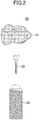
- FIG. 2 illustrates an example of the dentures plate system according to the present embodiment.
- the dentures plate system 20 includes a resin plate 21 having two access holes formed for screw fixation, two screws 22 used for fixing the resin plate 21, and two fixtures 23 capable of fixing the resin plate 21 with the screws 22.
- the resin plate 21 is provided for partial dentures when two back teeth are lost consecutively and is the same as the resin plate 10 except that two access holes for screw fixation are formed.
- the number of access holes formed in the resin plate 21 for fixing screws may be appropriately adjusted according to the condition of loss of teeth.
- the resin plate 21 is fabricated to correspond to the shape of the upper surface of the fixture 23. Therefore, it is possible to improve the stability of the dentures in the oral cavity.
- a material, from which the screw 22 is made, is not specifically limited.
- the material is ceramics, metals, etc.
- the outer diameter of screw 22 is typically 2-5 mm.
- the number of screws 22 is the same as the number of access holes for screw fixation formed in the resin plate 21.
- a screw hole corresponding to the shape of the screw 22 is formed in the fixture 23.
- a material, from which the fixture 23 is made, is not specifically limited.
- the material is titanium, a titanium alloy, etc.
- the number of fixtures 23 is the same as the number of access holes for screw fixation formed in the resin plate 21.
- two fixtures 23 are implanted in the alveolar bone of the portion of gingiva G in which the lost back tooth was generated. After placing the resin plate 21 on two fixtures 23, the resin plate 21 is then fixed with two screws 22. Next, the space of the access hole H of the resin plate 21 fixed with the screw 22 is filled with watte (cotton) 31 and temporarily sealed with temporary sealant 32.
- Temporary Stopping manufactured by GC Corporation
- GC Corporation Temporary Stopping
- the artificial tooth 41 are fixed to the upper portion of the resin plate 21 with cement (see FIG. 4 ).
- the artificial tooth 41 are for the partial dentures when two back teeth are lost in succession.
- a material, from which the artificial tooth 41 is made, is not specifically limited. For example, ceramics, metals, etc., may be used.
- the artificial tooth 41 may have two access holes for screw fixation on an occlusal surface. In this case, the artificial tooth 41 can be fixed with screws.
- FIG. 5 illustrates another example of the dentures plate system of the present embodiment.
- a dentures plate system 50 like the dentures plate system 20, includes a resin plate 51 having two access holes for screw fixation and two screws 52 for use in fixing the resin plate 51.
- the dentures plate system 50 further includes two abutments 53 which are capable of fixing the resin plate 51 with the screws 52, two screws 54 which are used to fix abutments 53, and two fixtures 55 which are capable of fixing the abutments 53 with the screws 54.
- the screw 52 is less likely to break.
- the resin plate 51 is the same as the resin plate 21 except that it is machined to correspond to the shape of the top surface of the abutment 53.
- a material, from which the screws 52, 54 are made, is not specifically limited.
- ceramics, metals, etc. may be used.
- the outer diameters of the screws 52 and 54 are typically 2-5 mm.
- the outer diameter of the screw 52 may or may not be the same as the outer diameter of the screw 54.
- the number of the screws 52, 54 is also the same as the number of the access holes for screw fixation formed in the resin plate 51.
- the abutment 53 is formed with a screw hole corresponding to the shape of the screw 52.
- the abutment 53 may be, for example, an abutment cylinder.
- the fixture 55 is the same as the fixture 23 except that a screw hole corresponding to the shape of the screw 54 is formed.
- the two fixtures 55 are implanted in the alveolar bone of the portion of the gingiva G in which the lost back tooth was generated.
- the abutment 53 is fitted onto each fixture 55 and then fixed with the screw 54 to the abutment 53.
- the resin plate 51 is fixed with the two screws 52.
- the space of the access hole H of the resin plate 51 fixed with the screws 52 is filled with watte (cotton) 61 and temporarily sealed with temporary sealant 62.
- Temporary Stopping manufactured by GC corporation
Landscapes
- Health & Medical Sciences (AREA)
- Oral & Maxillofacial Surgery (AREA)
- Animal Behavior & Ethology (AREA)
- Dentistry (AREA)
- Epidemiology (AREA)
- Life Sciences & Earth Sciences (AREA)
- General Health & Medical Sciences (AREA)
- Public Health (AREA)
- Veterinary Medicine (AREA)
- Orthopedic Medicine & Surgery (AREA)
- Engineering & Computer Science (AREA)
- Manufacturing & Machinery (AREA)
- Dental Prosthetics (AREA)
Abstract
In one mode of the present invention, a resin plate is manufactured by processing a resin disk using CAD/CAM, and an access hole for screw fixation is formed in the resin plate.
Description
- The present invention relates to a resin plate and dentures plate system.
- Dentures (sets of artificial teeth) include partial dentures (a partial set of artificial teeth) and complete dentures (a complete set of artificial teeth).
- The partial dentures (the partial set of artificial teeth) compensate locally for the function of the lost tooth when a part of the teeth in the maxilla and/or mandible is lost.
- The complete dentures (the complete set of artificial teeth) compensate for the lost tooth function when all teeth in the maxilla and/or mandible are lost.
- Here, the dentures (the sets of artificial teeth) have an artificial tooth and a resin plate, but is less stable in the oral cavity.
- On the other hand, implant dentures (removable implants) are attached to the fixture (artificial root) by an attachment (see, e.g., Patent Document 1).
- As the attachment, a ball attachment, a bar attachment, a magnet attachment, etc. are used.
- [Patent Document 1] International Patent Publication No.
2012/132057 - However, it is desirable to further improve stability of implant dentures in an oral cavity.
- If a resin plate is manufactured using a tray resin, the strength of the resin plate may be insufficient. In addition, it is necessary to polish the resin plate to adjust the shape.
- One mode of the present invention is directed to providing a resin plate that is excellent in strength, easy to adjust shape, and capable of improving the stability of the dentures in the oral cavity.
- In one mode of the present invention, a resin disk is processed by CAD/CAM to manufacture a resin plate, and a access hole for screw fixation is formed in the resin plate.
- According to one aspect of the present invention, a resin plate includes a resin having bending strength from 50 to 150 MPa (by JIS T 6518) and Vickers hardness from 12 to 28 Hv0.2, or a resin having bending strength from 50 to 300MPa (by JIS T 6517) and Vickers hardness from 18 to 110 Hv0.2, and includes an access hole for screw fixation formed therein.
- According to one mode of the present invention, a resin plate can be provided that is excellent in strength, easy to adjust its shape, and capable of improving the stability of the dentures in the oral cavity.
-
-
FIG. 1 illustrates an example of a resin plate according to the present embodiment. -
FIG. 2 illustrates an example of a dentures plate system according to the present embodiment. -
FIG. 3 illustrates an example of a method of using the dentures plate system ofFIG. 2 . -
FIG. 4 illustrates an example of a method of using the dentures plate system ofFIG. 2 . -
FIG. 5 illustrates another example of the dentures plate system according to the present embodiment. -
FIG. 6 illustrates an example of a method of using the dentures plate system ofFIG. 5 . - Next, an embodiment of the present invention will be described.
-
FIG. 1 illustrates an example of a resin plate of the present embodiment. - The
resin plate 10 is for complete dentures and is manufactured by processing a resin disk D with known CAD/CAM. Therefore, theresin plate 10 is excellent in strength and easy to adjust the shape. - The resin disk D is provided for CAD/CAM processing and ordinarily has bending strength and Vickers hardness from 50 to 150 MPa (or 50 to 300 MPa) and 12 to 28 Hv0.2 (or 18 to 110 Hv0.2), respectively, by JIS T 6518 (or JIS T 6517).
- A material, from which the resin disk D is made, is not specifically limited. The material is polymethyl methacrylate (PMMA), polycarbonate, polysulfone, polyether sulfone, etc.
- The resin disk D may also include a filler such as glass.
- Six "
access holes 11" for screw fixation are formed in theresin plate 10. Accordingly, theresin plate 10 can be fixed using 6 screws, optionally via abutments, to 6 fixtures embedded in the alveolar bone, thereby improving the stability of the complete dentures in the oral cavity. - The number of
access holes 11 that is for fixing using the screws and is formed in theresin plate 10 may be appropriately changed as necessary. - The shape of the
resin plate 10 is not particularly limited if machined to have a shape corresponding to the fixture or abutment. - The average inner diameter of the
access hole 11 for the screw fixation can be appropriately adjusted depending on the outer diameter of the screw, but is typically 2-5 mm. - A taper may be formed on the support portion of the
resin plate 10. - The
resin plate 10 may be reinforced by metal wires (metal wires), resin wires (resin wires), or the like. -
FIG. 2 illustrates an example of the dentures plate system according to the present embodiment. - The
dentures plate system 20 includes aresin plate 21 having two access holes formed for screw fixation, twoscrews 22 used for fixing theresin plate 21, and twofixtures 23 capable of fixing theresin plate 21 with thescrews 22. - The
resin plate 21 is provided for partial dentures when two back teeth are lost consecutively and is the same as theresin plate 10 except that two access holes for screw fixation are formed. - The number of access holes formed in the
resin plate 21 for fixing screws may be appropriately adjusted according to the condition of loss of teeth. - The
resin plate 21 is fabricated to correspond to the shape of the upper surface of thefixture 23. Therefore, it is possible to improve the stability of the dentures in the oral cavity. - A material, from which the
screw 22 is made, is not specifically limited. For example, the material is ceramics, metals, etc. - The outer diameter of
screw 22 is typically 2-5 mm. - The number of
screws 22 is the same as the number of access holes for screw fixation formed in theresin plate 21. - A screw hole corresponding to the shape of the
screw 22 is formed in thefixture 23. - A material, from which the
fixture 23 is made, is not specifically limited. For example, the material is titanium, a titanium alloy, etc. - The number of
fixtures 23 is the same as the number of access holes for screw fixation formed in theresin plate 21. - Next, an example of the method of using the
dentures plate system 20 will be described with reference toFIG. 3 . - First, two
fixtures 23 are implanted in the alveolar bone of the portion of gingiva G in which the lost back tooth was generated. After placing theresin plate 21 on twofixtures 23, theresin plate 21 is then fixed with twoscrews 22. Next, the space of the access hole H of theresin plate 21 fixed with thescrew 22 is filled with watte (cotton) 31 and temporarily sealed withtemporary sealant 32. - As the
temporary sealant 32, for example, Temporary Stopping (manufactured by GC Corporation) can be used. - Finally, the
artificial tooth 41 are fixed to the upper portion of theresin plate 21 with cement (seeFIG. 4 ). - The
artificial tooth 41 are for the partial dentures when two back teeth are lost in succession. A material, from which theartificial tooth 41 is made, is not specifically limited. For example, ceramics, metals, etc., may be used. - The
artificial tooth 41 may have two access holes for screw fixation on an occlusal surface. In this case, theartificial tooth 41 can be fixed with screws. -
FIG. 5 illustrates another example of the dentures plate system of the present embodiment. - A
dentures plate system 50, like thedentures plate system 20, includes aresin plate 51 having two access holes for screw fixation and twoscrews 52 for use in fixing theresin plate 51. - The
dentures plate system 50 further includes twoabutments 53 which are capable of fixing theresin plate 51 with thescrews 52, twoscrews 54 which are used to fixabutments 53, and twofixtures 55 which are capable of fixing theabutments 53 with thescrews 54. - Because the
dentures plate system 50 has theabutment 53, thescrew 52 is less likely to break. - The
resin plate 51 is the same as theresin plate 21 except that it is machined to correspond to the shape of the top surface of theabutment 53. - A material, from which the
screws - The outer diameters of the
screws - The outer diameter of the
screw 52 may or may not be the same as the outer diameter of thescrew 54. - The number of the
screws resin plate 51. - The
abutment 53 is formed with a screw hole corresponding to the shape of thescrew 52. - The
abutment 53 may be, for example, an abutment cylinder. - The
fixture 55 is the same as thefixture 23 except that a screw hole corresponding to the shape of thescrew 54 is formed. - Next, an example of the method of using the
dentures plate system 50 will be described with reference toFIG. 6 . - First, the two
fixtures 55 are implanted in the alveolar bone of the portion of the gingiva G in which the lost back tooth was generated. Next, theabutment 53 is fitted onto eachfixture 55 and then fixed with thescrew 54 to theabutment 53. In addition, after placing theresin plate 51 on twoabutments 53, theresin plate 51 is fixed with the twoscrews 52. Next, the space of the access hole H of theresin plate 51 fixed with thescrews 52 is filled with watte (cotton) 61 and temporarily sealed withtemporary sealant 62. - As the
temporary sealant 62, for example, Temporary Stopping (manufactured by GC corporation) can be used. - Finally, artificial teeth are fixed on the
resin plate 51 using cement, screws, or the like. - This international application claims priority to Japanese Patent Application No.
2017-037654 filed February 28, 2017 2017-037654 -
- 10
- Resin plate
- 11
- Through hole for screw fixation
- D
- Resin disk
- 20, 50
- Dentures plate system
- 21, 51
- Resin plate
- 22, 52, 54
- Screw
- 23, 55
- Fixture
- 53
- Abutment
- H
- Access hole
- 31, 61
- Watte (Cotton)
- 32, 62
- Temporary sealant
- G
- Gingiva
- 41
- Artificial tooth
Claims (6)
- A resin plate manufactured by processing a resin disk using CAD/CAM and having an access hole formed for fixing a screw.
- A resin plate comprising:a resin whose bending strength and Vickers hardness are from 50 to 150 MPa and 12 to 28 Hv0.2 (by JIS T 6518), respectively, or the bending strength and Vickers hardness are from 50 to 300 MPa and 18 to 110 Hv0.2 (by JIS T 6517), respectively, andan access hole formed for fixing a screw.
- A dentures plate system comprising:the resin plate according to claim 1;the screw configured to fix the resin plate; anda fixture configured to fix the resin plate using the screw.
- The dentures plate system according to claim 3, wherein the resin plate is processed to correspond to a shape of the fixture.
- A resin plate system comprising:the resin plate according to claim 1;the first screw used to fix the resin plate;an abutment configured to fix the resin plate using the first screw;a second screw configured to fix the abutment; anda fixture configured to fix the abutment with the second screw.
- The resin plate system according to claim 5, wherein the resin plate is processed to correspond to a shape of the abutment.
Applications Claiming Priority (2)
| Application Number | Priority Date | Filing Date | Title |
|---|---|---|---|
| JP2017037654 | 2017-02-28 | ||
| PCT/JP2017/044531 WO2018159059A1 (en) | 2017-02-28 | 2017-12-12 | Resin base and denture base system |
Publications (1)
| Publication Number | Publication Date |
|---|---|
| EP3590465A1 true EP3590465A1 (en) | 2020-01-08 |
Family
ID=63369896
Family Applications (1)
| Application Number | Title | Priority Date | Filing Date |
|---|---|---|---|
| EP17898565.1A Withdrawn EP3590465A1 (en) | 2017-02-28 | 2017-12-12 | Resin base and denture base system |
Country Status (5)
| Country | Link |
|---|---|
| US (1) | US20190343605A1 (en) |
| EP (1) | EP3590465A1 (en) |
| JP (1) | JPWO2018159059A1 (en) |
| CN (1) | CN110267621A (en) |
| WO (1) | WO2018159059A1 (en) |
Family Cites Families (10)
| Publication number | Priority date | Publication date | Assignee | Title |
|---|---|---|---|---|
| US4445862A (en) * | 1981-11-25 | 1984-05-01 | Mont-Cler Appliances Inc. | Precision pontic and method for making it |
| KR100537218B1 (en) * | 2003-03-13 | 2005-12-16 | 허영구 | Abutment for a implant using a screw-cement retained prosthesis |
| US8529255B2 (en) * | 2009-01-16 | 2013-09-10 | V2R Biomedical Inc | Dental prosthesis system |
| KR101799873B1 (en) * | 2010-10-01 | 2017-11-22 | 쓰리세이프 에이/에스 | Modeling and manufacturing of dentures |
| JP5100918B2 (en) | 2011-03-28 | 2012-12-19 | 株式会社T・U・M | Denture system, denture creation method and repair method |
| US8555584B2 (en) * | 2011-09-28 | 2013-10-15 | Romeo Ilarian Ciuperca | Precast concrete structures, precast tilt-up concrete structures and methods of making same |
| GB201120375D0 (en) * | 2011-11-25 | 2012-01-11 | Invibio Ltd | Prosthodontic device |
| US20150272705A1 (en) * | 2014-03-28 | 2015-10-01 | Jason Watson | Dental device comprising surgical template and false teeth set and related methods |
| CN105616020A (en) * | 2016-03-07 | 2016-06-01 | 杭州口腔医院有限公司 | Preparation method of CAD/CAM personalized resin pre-formed crown and bridge |
| JP6332369B2 (en) | 2016-09-08 | 2018-05-30 | 株式会社ニコン | Information processing apparatus and program |
-
2017
- 2017-12-12 WO PCT/JP2017/044531 patent/WO2018159059A1/en not_active Ceased
- 2017-12-12 JP JP2019502468A patent/JPWO2018159059A1/en active Pending
- 2017-12-12 EP EP17898565.1A patent/EP3590465A1/en not_active Withdrawn
- 2017-12-12 US US16/480,745 patent/US20190343605A1/en not_active Abandoned
- 2017-12-12 CN CN201780086191.XA patent/CN110267621A/en active Pending
Also Published As
| Publication number | Publication date |
|---|---|
| WO2018159059A1 (en) | 2018-09-07 |
| CN110267621A (en) | 2019-09-20 |
| US20190343605A1 (en) | 2019-11-14 |
| JPWO2018159059A1 (en) | 2019-11-14 |
Similar Documents
| Publication | Publication Date | Title |
|---|---|---|
| US7632095B2 (en) | Method for forming a dental prosthesis | |
| KR102302292B1 (en) | Molds for custom dental implant abutments and impression posts | |
| Döring et al. | Functional and esthetic considerations for single-tooth Ankylos implant-crowns: 8 years of clinical performance | |
| Chee et al. | Failures in implant dentistry | |
| JP2019005599A (en) | Manufacturing method of tooth abutment for dental prosthesis support | |
| Melsen | Mini-implants: where are we? | |
| JP2021526400A (en) | Central gingival implant system | |
| SE0203507L (en) | Dental implants designed in one piece | |
| KR102613796B1 (en) | Dental assemblies including adapters and adapters for attaching dental superstructures to dental implants. | |
| US20160008105A1 (en) | Dental prostheses cemented onto implants and/or abutments having a reverse margin | |
| US20260007496A1 (en) | Adaptor for dental implant abutment | |
| US20110212417A1 (en) | Insertion part of a two-part implant with insertion instrument | |
| Ozkir et al. | Effects of crown retrieval on implants and the surrounding bone: a finite element analysis | |
| US10682208B2 (en) | Abutment assembly and manufacturing method thereof | |
| Gayathridevi et al. | Impression techniques in implants | |
| Dittmer et al. | Load-bearing capacity of screw-retained CAD/CAM-produced titanium implant frameworks (I-Bridge® 2) before and after cyclic mechanical loading | |
| US20190343605A1 (en) | Resin plate and dentures plate system | |
| Ormianer et al. | Stress and strain patterns of 1-piece and 2-piece implant systems in bone: a 3-dimensional finite element analysis | |
| KR101429659B1 (en) | Dental implant abutment and dental implant assembly with the same | |
| KR20160008322A (en) | screw of implant | |
| EP2764843A1 (en) | A hybrid abutment system | |
| Gunaseelan et al. | Overview of the SwissPlus implant system | |
| JP2012196363A (en) | Method for manufacturing titanium dental implant abutment | |
| JP2010540138A (en) | Dual function system for dental implants | |
| EP2801336A2 (en) | Implant system |
Legal Events
| Date | Code | Title | Description |
|---|---|---|---|
| PUAI | Public reference made under article 153(3) epc to a published international application that has entered the european phase |
Free format text: ORIGINAL CODE: 0009012 |
|
| 17P | Request for examination filed |
Effective date: 20190808 |
|
| AK | Designated contracting states |
Kind code of ref document: A1 Designated state(s): AL AT BE BG CH CY CZ DE DK EE ES FI FR GB GR HR HU IE IS IT LI LT LU LV MC MK MT NL NO PL PT RO RS SE SI SK SM TR |
|
| AX | Request for extension of the european patent |
Extension state: BA ME |
|
| DAV | Request for validation of the european patent (deleted) | ||
| DAX | Request for extension of the european patent (deleted) | ||
| STAA | Information on the status of an ep patent application or granted ep patent |
Free format text: STATUS: THE APPLICATION HAS BEEN WITHDRAWN |
|
| 18W | Application withdrawn |
Effective date: 20200810 |