EP3590094B1 - Augmented reality display for material moving machines - Google Patents
Augmented reality display for material moving machines Download PDFInfo
- Publication number
- EP3590094B1 EP3590094B1 EP18760630.6A EP18760630A EP3590094B1 EP 3590094 B1 EP3590094 B1 EP 3590094B1 EP 18760630 A EP18760630 A EP 18760630A EP 3590094 B1 EP3590094 B1 EP 3590094B1
- Authority
- EP
- European Patent Office
- Prior art keywords
- implement
- virtual
- material moving
- image
- terrain
- Prior art date
- Legal status (The legal status is an assumption and is not a legal conclusion. Google has not performed a legal analysis and makes no representation as to the accuracy of the status listed.)
- Active
Links
Images


Classifications
-
- E—FIXED CONSTRUCTIONS
- E02—HYDRAULIC ENGINEERING; FOUNDATIONS; SOIL SHIFTING
- E02F—DREDGING; SOIL-SHIFTING
- E02F9/00—Component parts of dredgers or soil-shifting machines, not restricted to one of the kinds covered by groups E02F3/00 - E02F7/00
- E02F9/26—Indicating devices
- E02F9/261—Surveying the work-site to be treated
-
- B—PERFORMING OPERATIONS; TRANSPORTING
- B60—VEHICLES IN GENERAL
- B60R—VEHICLES, VEHICLE FITTINGS, OR VEHICLE PARTS, NOT OTHERWISE PROVIDED FOR
- B60R1/00—Optical viewing arrangements; Real-time viewing arrangements for drivers or passengers using optical image capturing systems, e.g. cameras or video systems specially adapted for use in or on vehicles
- B60R1/20—Real-time viewing arrangements for drivers or passengers using optical image capturing systems, e.g. cameras or video systems specially adapted for use in or on vehicles
- B60R1/22—Real-time viewing arrangements for drivers or passengers using optical image capturing systems, e.g. cameras or video systems specially adapted for use in or on vehicles for viewing an area outside the vehicle, e.g. the exterior of the vehicle
- B60R1/23—Real-time viewing arrangements for drivers or passengers using optical image capturing systems, e.g. cameras or video systems specially adapted for use in or on vehicles for viewing an area outside the vehicle, e.g. the exterior of the vehicle with a predetermined field of view
- B60R1/24—Real-time viewing arrangements for drivers or passengers using optical image capturing systems, e.g. cameras or video systems specially adapted for use in or on vehicles for viewing an area outside the vehicle, e.g. the exterior of the vehicle with a predetermined field of view in front of the vehicle
-
- E—FIXED CONSTRUCTIONS
- E02—HYDRAULIC ENGINEERING; FOUNDATIONS; SOIL SHIFTING
- E02F—DREDGING; SOIL-SHIFTING
- E02F3/00—Dredgers; Soil-shifting machines
- E02F3/04—Dredgers; Soil-shifting machines mechanically-driven
- E02F3/28—Dredgers; Soil-shifting machines mechanically-driven with digging tools mounted on a dipper- or bucket-arm, i.e. there is either one arm or a pair of arms, e.g. dippers, buckets
- E02F3/30—Dredgers; Soil-shifting machines mechanically-driven with digging tools mounted on a dipper- or bucket-arm, i.e. there is either one arm or a pair of arms, e.g. dippers, buckets with a dipper-arm pivoted on a cantilever beam, i.e. boom
- E02F3/32—Dredgers; Soil-shifting machines mechanically-driven with digging tools mounted on a dipper- or bucket-arm, i.e. there is either one arm or a pair of arms, e.g. dippers, buckets with a dipper-arm pivoted on a cantilever beam, i.e. boom working downwardly and towards the machine, e.g. with backhoes
-
- E—FIXED CONSTRUCTIONS
- E02—HYDRAULIC ENGINEERING; FOUNDATIONS; SOIL SHIFTING
- E02F—DREDGING; SOIL-SHIFTING
- E02F3/00—Dredgers; Soil-shifting machines
- E02F3/04—Dredgers; Soil-shifting machines mechanically-driven
- E02F3/28—Dredgers; Soil-shifting machines mechanically-driven with digging tools mounted on a dipper- or bucket-arm, i.e. there is either one arm or a pair of arms, e.g. dippers, buckets
- E02F3/36—Component parts
- E02F3/42—Drives for dippers, buckets, dipper-arms or bucket-arms
- E02F3/43—Control of dipper or bucket position; Control of sequence of drive operations
- E02F3/435—Control of dipper or bucket position; Control of sequence of drive operations for dipper-arms, backhoes or the like
-
- E—FIXED CONSTRUCTIONS
- E02—HYDRAULIC ENGINEERING; FOUNDATIONS; SOIL SHIFTING
- E02F—DREDGING; SOIL-SHIFTING
- E02F9/00—Component parts of dredgers or soil-shifting machines, not restricted to one of the kinds covered by groups E02F3/00 - E02F7/00
- E02F9/20—Drives; Control devices
- E02F9/22—Hydraulic or pneumatic drives
- E02F9/2264—Arrangements or adaptations of elements for hydraulic drives
- E02F9/2271—Actuators and supports therefor and protection therefor
-
- E—FIXED CONSTRUCTIONS
- E02—HYDRAULIC ENGINEERING; FOUNDATIONS; SOIL SHIFTING
- E02F—DREDGING; SOIL-SHIFTING
- E02F9/00—Component parts of dredgers or soil-shifting machines, not restricted to one of the kinds covered by groups E02F3/00 - E02F7/00
- E02F9/24—Safety devices, e.g. for preventing overload
- E02F9/245—Safety devices, e.g. for preventing overload for preventing damage to underground objects during excavation, e.g. indicating buried pipes or the like
-
- E—FIXED CONSTRUCTIONS
- E02—HYDRAULIC ENGINEERING; FOUNDATIONS; SOIL SHIFTING
- E02F—DREDGING; SOIL-SHIFTING
- E02F9/00—Component parts of dredgers or soil-shifting machines, not restricted to one of the kinds covered by groups E02F3/00 - E02F7/00
- E02F9/26—Indicating devices
- E02F9/261—Surveying the work-site to be treated
- E02F9/262—Surveying the work-site to be treated with follow-up actions to control the work tool, e.g. controller
-
- E—FIXED CONSTRUCTIONS
- E02—HYDRAULIC ENGINEERING; FOUNDATIONS; SOIL SHIFTING
- E02F—DREDGING; SOIL-SHIFTING
- E02F9/00—Component parts of dredgers or soil-shifting machines, not restricted to one of the kinds covered by groups E02F3/00 - E02F7/00
- E02F9/26—Indicating devices
- E02F9/264—Sensors and their calibration for indicating the position of the work tool
-
- E—FIXED CONSTRUCTIONS
- E02—HYDRAULIC ENGINEERING; FOUNDATIONS; SOIL SHIFTING
- E02F—DREDGING; SOIL-SHIFTING
- E02F9/00—Component parts of dredgers or soil-shifting machines, not restricted to one of the kinds covered by groups E02F3/00 - E02F7/00
- E02F9/26—Indicating devices
- E02F9/264—Sensors and their calibration for indicating the position of the work tool
- E02F9/265—Sensors and their calibration for indicating the position of the work tool with follow-up actions (e.g. control signals sent to actuate the work tool)
-
- G—PHYSICS
- G06—COMPUTING OR CALCULATING; COUNTING
- G06T—IMAGE DATA PROCESSING OR GENERATION, IN GENERAL
- G06T19/00—Manipulating three-dimensional [3D] models or images for computer graphics
- G06T19/006—Mixed reality
-
- B—PERFORMING OPERATIONS; TRANSPORTING
- B60—VEHICLES IN GENERAL
- B60R—VEHICLES, VEHICLE FITTINGS, OR VEHICLE PARTS, NOT OTHERWISE PROVIDED FOR
- B60R2300/00—Details of viewing arrangements using cameras and displays, specially adapted for use in a vehicle
- B60R2300/30—Details of viewing arrangements using cameras and displays, specially adapted for use in a vehicle characterised by the type of image processing
- B60R2300/304—Details of viewing arrangements using cameras and displays, specially adapted for use in a vehicle characterised by the type of image processing using merged images, e.g. merging camera image with stored images
- B60R2300/305—Details of viewing arrangements using cameras and displays, specially adapted for use in a vehicle characterised by the type of image processing using merged images, e.g. merging camera image with stored images merging camera image with lines or icons
-
- G—PHYSICS
- G06—COMPUTING OR CALCULATING; COUNTING
- G06T—IMAGE DATA PROCESSING OR GENERATION, IN GENERAL
- G06T17/00—Three-dimensional [3D] modelling for computer graphics
Definitions
- the present disclosure relates to material moving machines and, in some embodiments, to material moving machines including material moving implements, such as excavators including excavating implements.
- material moving machines including material moving implements, such as excavators including excavating implements.
- Such excavators for the purposes of defining and describing the scope of the present application, comprise an excavator boom and an excavator stick subject to swing and curl, and an excavating implement that is subject to swing and curl control with the aid of the excavator boom and excavator stick, or other similar components for executing swing and curl movement.
- many types of excavators comprise a hydraulically or pneumatically or electrically controlled excavating implement that can be manipulated by controlling the swing and curl functions of an excavating linkage assembly of the excavator.
- Excavator technology is, for example, well represented by the disclosures of US 8,689,471, which is assigned to Caterpillar Trimble Control Technologies LLC and discloses methodology for sensor-based automatic control of an excavator, US 2008/0047170 , which is assigned to Caterpillar Trimble Control Technologies LLC and discloses an excavator 3D laser system and radio positioning guidance system configured to guide a cutting edge of an excavator bucket with high vertical accuracy, and US 2008/0000111 , which is assigned to Caterpillar Trimble Control Technologies LLC and discloses methodology for an excavator control system to determine an orientation of an excavator sitting on a sloped site, for example.
- US 2017/0028922 discloses an excavation device comprising a stereo camera, a means for recognising a bucket from an image photographed by the camera, and measuring a position of the bucket.
- US 2011/0311342 discloses a combination of location measurement apparatuses to measure in three dimensions the location of an excavator with respect to a job site.
- US 6282477 discloses a method and apparatus for locating earthworking implements at working sites and displaying a three-dimensional image of a portion of an object within a perimeter of interest.
- an excavator comprises a machine chassis, an excavating linkage assembly, an excavating implement, a camera, a display, and guidance architecture
- the excavating linkage assembly comprises an excavator boom and an excavator stick that collectively define a plurality of linkage assembly positions.
- the excavating linkage assembly is configured to swing with, or relative to, the machine chassis.
- the excavator stick is configured to curl relative to the excavator boom.
- the excavating implement is mechanically coupled to the excavator stick.
- the camera is positioned on the excavator such that a field of view of the camera encompasses a view of the excavating implement and a terrain.
- the guidance architecture comprises one or more dynamic sensors, one or more linkage assembly actuators configured to actuate the excavating linkage assembly through the plurality of linkage assembly positions, and an architecture controller.
- the architecture controller is programmed to generate a camera image from the camera, the camera image comprising the excavating implement in relation to the terrain, generate a virtual implement bar configured to be disposed as on a leading edge of the excavating implement, generate a virtual target bar of a design surface configured to be disposed as part of the terrain at least partially based on a position of the excavating implement, overlay the virtual implement bar and the virtual target bar on the camera image to generate an augmented reality overlay image, and display the augmented reality overlay image on the display.
- the architecture controller is programmed to generate a camera image from the camera, the camera image comprising the excavating implement in relation to the terrain, generate a virtual trench configured to be disposed as part of the terrain at least partially based on a position of the excavating implement, superimpose the virtual trench on the camera image to generate an augmented reality overlay image, and display the augmented reality overlay image on the display.
- the architecture controller is programmed to store geometry data of underground features of the terrain, generate a camera image from the camera, the camera image comprising the excavating implement in relation to the terrain, and generate a virtual trench configured to be disposed as part of the terrain at least partially based on the superimposed portion of a position of the excavating implement.
- the architecture controller is further programmed to generate a superimposed image of the virtual trench on the camera image, overlay the underground features within the virtual trench on the superimposed image to generate an augmented reality overlay image, and display the augmented reality overlay image on the display.
- a material moving machine comprises an material moving implement, a camera positioned on the material moving machine and comprising a field of view that encompasses the material moving implement and terrain in a working area of the material moving implement, an augmented display, and control architecture comprising one or more dynamic sensors configured to generate a position signal representing a position of the material moving implement characterised in that the control architecture further comprising an architecture controller comprising a memory and an image generator communicatively coupled to the augmented display.
- the architecture controller is programmed to store in the memory a three-dimensional model of underground features of the terrain, capture an implement image by the camera, the implement image comprising the material moving implement and terrain in the working area of the material moving implement, generate through the image generator a superimposed image by superimposing corresponding portions of the implement image and the three-dimensional model of underground features, generate a virtual trench based on the position of the material moving implement, overlay the virtual trench on the superimposed image to generate an augmented reality overlay image comprising the virtual trench and the superimposed portions of the implement image and the three-dimensional model of underground features, generate through the image generator the augmented reality overlay image, and display the augmented reality overlay image on the augmented display.
- an excavator comprises a machine chassis, an excavating implement, an excavating linkage assembly comprising an excavator boom and an excavator stick that collectively define a plurality of linkage assembly positions
- the excavating linkage assembly is configured to swing with, or relative to, the machine chassis
- the excavator stick is configured to curl relative to the excavator boom
- the excavating implement is mechanically coupled to the excavator stick
- a camera positioned on the excavator and comprising a field of view that encompasses the excavating implement and terrain in the working area of the excavating implement
- control architecture comprising one or more dynamic sensors configured to generate a position signal representing a position of the excavating implement, one or more linkage assembly actuators configured to actuate the excavating linkage assembly through the plurality of linkage assembly positions
- an architecture controller comprising a memory and an image generator communicatively coupled to the augmented display.
- the architecture controller is programmed to store in the memory a three-dimensional model of underground features of the terrain, capture an implement image by the camera, the implement image comprising the excavating implement and terrain in the working area of the excavating implement, generate through the image generator a superimposed image by superimposing corresponding portions of the implement image and the three-dimensional model of underground features, generate a virtual trench based on a position of a leading implement edge of the excavating implement in relation to a longitudinally disposed surface portion of the terrain disposed beneath the leading implement edge, and overlay the virtual trench on the superimposed image to generate through the image generator an augmented reality overlay image comprising the virtual trench and the superimposed portions of the implement image and the three-dimensional model of underground features.
- a virtual implement bar is superimposed over a leading implement edge of the excavating implement, and a virtual target bar is superimposed over a longitudinally disposed surface portion of the terrain.
- the architecture controller is further programmed to adjust the virtual trench based on a position of the virtual implement bar with respect to the virtual target bar on the terrain and display the augmented reality overlay image on the augmented display.
- a method of operating a material moving machine utilizing an augmented display comprises disposing the material moving machine on terrain, the material moving machine comprising an material moving implement, a camera, the augmented display, and control architecture.
- the camera is positioned on the excavator and comprises a field of view that encompasses the material moving implement and terrain in a working area of the material moving implement
- the control architecture comprises one or more dynamic sensors configured to generate a position signal representing a position of the material moving implement, a memory, and an image generator communicatively coupled to the augmented display.
- the method further comprises storing in the memory a three-dimensional model of underground features of the terrain, capturing an implement image by the camera, the implement image comprising the material moving implement and terrain in the working area of the material moving implement, generating through the image generator a superimposed image by superimposing corresponding portions of the implement image and the three-dimensional model of underground features, generating a virtual trench based on the position of the material moving implement, overlaying the virtual trench on the superimposed image to generate an augmented reality overlay image comprising the virtual trench and the superimposed portions of the implement image and the three-dimensional model of underground features, generating through the image generator the augmented reality overlay image, displaying the augmented reality overlay image on the augmented display, operating the material moving machine utilizing the control architecture to move the material moving implement with respect to the terrain based on the augmented reality overlay image, generating the virtual trench based on a position of a leading implement edge of the material moving implement in relation to a longitudinally disposed surface portion of the terrain disposed beneath the leading implement edge; and generating the augmented reality overlay image compris
- the concepts of the present disclosure are described herein with primary reference to the excavator illustrated in FIG. 1 as a material moving machine, it is contemplated that the concepts will enjoy applicability to any type of material moving machine, regardless of its particular mechanical configuration.
- the concepts may enjoy applicability to a backhoe loader including a backhoe linkage.
- a material moving machine comprises a material moving implement and is designed to excavate, distribute, smooth, or otherwise move a material using the material moving implement.
- Examples of such machines include, but are not limited to, excavators, backhoe loaders, dozers, pavers, motor graders, loaders, trenchers, scrapers, drills, crushers, draglines, or any type of machine that includes an implement for moving material.
- Contemplated materials include, but are not limited to, soil or other surface-based earth materials, subterranean materials, including materials to be mined, and construction aggregates, including, for example, substrate materials and paving materials.
- the material moving machines may be excavators including components subject to adaptive control.
- many types of excavators typically have a hydraulically controlled material moving implement that can be manipulated by a joystick or other means in an operator control station of the machine, and is also subject to partially or fully automated adaptive control.
- the user of the machine may control the lift, tilt, angle, and pitch of the implement.
- one or more of these variables may also be subject to partially or fully automated control based on information sensed or received by an adaptive environmental sensor of the machine.
- an excavator comprises a display configured to display an augmented reality overlay image including a virtual implement bar, a virtual target bar of a design surface, and/or a virtual trench.
- the virtual trench comprises underground features.
- the virtual trench may not comprise underground features.
- the virtual trench is adjustably positioned automatically based on a position of an excavating implement. For example, the position of the excavator implement is captured by a camera of the excavator and/or determined through signals from one or more dynamic sensors, as described in greater detail further below. Alternatively or additionally, the virtual trench is adjustably positioned automatically based on rotation of the excavator.
- Such an augmented reality overlay image may be utilized by an excavator control and/or excavator operator to operate the excavator.
- an excavator control and/or excavator operator to operate the excavator.
- the physical terrain image is augmented by virtual data to present the excavator operator with an augmented reality camera view as the augmented reality overlap image described in greater detail further below.
- the virtual trench may be intended to representative of an actual ditch to be dug. In other embodiments, the virtual trench may not be intended to be representative of an actual ditch to be dug but rather be intended to visualize subsurface features including the design surface in a manner that enables intuitive depth perception by utilizing an operator's understanding of a size and location of the excavating implement.
- the virtual trench may be representative of a trench that would be dug if the excavating implement were to dig vertically down from a current location to the design surface and then pull in towards the excavator along the design surface.
- the virtual trench has a same width as a leading implement edge of the excavating implement and is disposed with the leading implement edge oriented in a direction towards the center of the excavator. Further, as the excavating implement moves in to or away from the operator and/or as the excavator rotates (i.e., slews), the virtual trench adjustably moves, as described in greater detail further below.
- generation of the virtual trench is at least partially based on terrain surface location to position and display lines representing a top of the virtual trench on a terrain surface, which terrain surface location may be estimated or measured. For example, a roll and pitch of the excavator may be projected to form a plane surface in front of the excavator to utilize as the terrain surface location.
- a surface scanner may be used such as a LIDAR, RADAR, or photogrammetry based scanner for such terrain surface location data.
- GNSS-based vehicle mapping may be used to measure the terrain surface as the material moving machine moves around the site (also known as track mapping), the terrain surface may be estimated by measuring the movement of the implement, and/or at least one of terrain data from manual and aerial surveys may be used that is transferred to and stored by the guidance architecture of the excavator.
- an excavator 100 comprises a machine chassis 102, an excavating linkage assembly 104, an excavating implement 114, a camera 124, a display 125, and guidance architecture 106.
- the guidance architecture comprises control architecture responsive to operator action through manual control of levers and/or linkages and/or responsive to automatic action by a controller of the excavator 100.
- the excavating linkage assembly 104 comprises an excavator boom 108 and an excavator stick 110 that collectively define a plurality of linkage assembly positions.
- the camera 124 is positioned on the excavator 100 such that a field of view of the camera 124 encompasses a view of the excavating implement 114 and a terrain 126.
- the excavator 100 comprises a boom dynamic sensor 120, a stick dynamic sensor 122, an implement dynamic sensor 123, or combinations thereof.
- the boom dynamic sensor 120 is positioned on the excavator boom 108
- the stick dynamic sensor 122 is positioned on the excavator stick 110
- the implement dynamic sensor 123 is positioned on the excavating implement 114.
- the dynamic sensor 120, 122, 123 may comprise a global navigation satellite system (GNSS) receiver, a global positioning system (GPS) receiver, a Universal Total Station (UTS) and machine target, an inertial measurement unit (IMU), an inclinometer, an accelerometer, a gyroscope, an angular rate sensor, a rotary position sensor, a position sensing cylinder, or combinations thereof, or any sensor or combination of sensors that provide signals indicative of an operational characteristic of a component of the material moving machine such as the excavator 100.
- the dynamic sensor 120, 122, 123 may comprise an IMU comprising a 3-axis accelerometer and a 3-axis gyroscope.
- the dynamic sensor 120, 122, 123 may include x-axis, y-axis, and z-axis acceleration values.
- the excavating linkage assembly 104 may be configured to define a linkage assembly heading N ⁇ and to swing with, or relative to, the machine chassis 102 about a swing axis S of the excavator 100.
- the excavator stick 110 is configured to curl relative to the excavator boom 108.
- the excavator stick 110 may be configured to curl relative to the excavator boom 108 about a curl axis C of the excavator 100.
- the excavator boom 108 and excavator stick 110 of the excavator 100 illustrated in FIG. 1 are linked by a simple mechanical coupling that permits movement of the excavator stick 110 in one degree of rotational freedom relative to the excavator boom 108.
- the linkage assembly heading N ⁇ will correspond to the heading of the excavator boom 108.
- the present disclosure also contemplates the use of excavators equipped with offset booms where the excavator boom 108 and excavator stick 110 are linked by a multidirectional coupling that permits movement in more than one rotational degree of freedom. See, for example, the excavator illustrated in US 7,869,923 ("Slewing Controller, Slewing Control Method, and Construction Machine").
- the linkage assembly heading N ⁇ will correspond to the heading of the excavator stick 110.
- the excavating implement 114 is mechanically coupled to the excavator stick 110.
- the excavating implement 114 is mechanically coupled to the excavator stick 110 through an implement coupling 112.
- the excavating implement 114 may be mechanically coupled to the excavator stick 110 via the implement coupling 112 and configured to rotate about a rotary axis R.
- the rotary axis R may be defined by the implement coupling 112 joining the excavator stick 110 and the rotary excavating implement 114.
- the rotary axis R may be defined by a multidirectional, stick coupling joining the excavator boom 108 and the excavator stick 110 along the plane P such that the excavator stick 110 is configured to rotate about the rotary axis R.
- Rotation of the excavator stick 110 about the rotary axis R defined by the stick coupling may result in a corresponding rotation of the rotary excavating implement 114, which is coupled to the excavator stick 110, about the rotary axis R defined by the stick coupling.
- the guidance architecture 106 comprises one or more dynamic sensors, one or more linkage assembly actuators, and an architecture controller programmed to execute the steps of a control scheme, such as a control scheme 190 of FIG. 5A or a control scheme 200 of FIG. 5B , each of which are described in greater detail further below.
- the guidance architecture 106 may comprise a non-transitory computer-readable storage medium, such as memory, comprising machine readable instructions.
- the guidance architecture 106 may also comprise a processor communicatively coupled to the non-transitory computer-readable storage medium and configured to execute the machine readable instructions.
- the one or more linkage assembly actuators facilitate movement of the excavating linkage assembly 104.
- the one or more linkage assembly actuators comprise a hydraulic cylinder actuator, a pneumatic cylinder actuator, an electrical actuator, a mechanical actuator, or combinations thereof.
- the architecture controller is programmed to generate an implement image 130 from the camera 124 in step 192.
- the architecture controller is programmed to capture an implement image as the capture image 130, the implement image comprising the excavating implement 114 and terrain in the working area of the excavating implement 114.
- the implement image 130 comprises the excavating implement 114 in relation to the terrain 126.
- the architecture controller is further programmed to generate a virtual trench 132 configured to be disposed as part of the terrain 126 at least partially based on a position of the excavating implement 114 in step 194.
- the architecture controller may generate a signal indicative of the position and/or orientation of the excavating implement 114 and spacing with respect to terrain 126, as described in greater detail further below, from the one or more dynamic sensors 120, 122, 123.
- the architecture controller is further programmed to generate an image of the virtual trench 132 superimposed on the implement image 130 to generate an augmented reality overlay image 134 in step 196, and to display the augmented reality overlay image 134 on the display 125 in step 198.
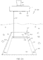
- FIG. 2A illustrates a view of an augmented reality overlay image 134 including the virtual trench 132 without underground features.
- the view of an augmented reality overlay image 134A may be displayed with underground features.
- the architecture controller may be further programmed to generate the augmented reality overlay image to reveal underground features of the three-dimensional model within the virtual trench 132 and to occlude underground features of the three-dimensional model outside of the virtual trench 132.
- the implement image 130 comprises the excavating implement 114 in relation to the terrain 126 and an augmented reality overlay image 134A, 134B, 134C displays a virtual trench 132 including underground features such as pipes 190, 192 for display on the display 125.
- FIG. 2C illustrates a first view of such an augmented reality overlay image 134A.
- the augmented reality overlay image 134, 134' may be displayed without underground features.
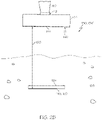
- the augmented reality overlay image 134' is displayed without the virtual trench 132 or the underground features while displaying a virtual target implement bar 144 and a virtual target bar 146 of a design surface 150, which are described in greater detail further below.
- augmented reality overlay images may be displayed with one or more portions of the virtual trench 132 while omitting other one or more portions of the virtual trench 132, For example, a nearest trench boundary of the virtual trench 132 may be omitted from the display such that the virtual trench 132 appears to extend under the excavator 100 and outside of the view of the camera 124.
- Sub-visualizations and/or expandable visualizations of such augmented reality overlay images may be displayed, such as a first display as illustrated in FIG. 2C of the virtual trench 132 including underground features that may be narrowed to a display of the virtual trench 132 without underground features as displayed in FIG. 2A and/or that may be narrowed to a display of the virtual target bar 146 without the virtual trench 132 as displayed in FIG. 2B .
- such displays may be expanded to add components and features as described herein and/or may be displayed in a shared screen space of the display 125.
- the first view of an augmented reality overlay image 134A may be displayed with underground features.
- the architecture controller is programmed to store geometry data of underground features of the terrain 126 in step 202.
- the geometry data of underground features may be stored as two-dimensional and/or three-dimensional geometry information.
- additional underground feature information may be stored by the architecture controller that may or may not match a display of a two-dimensional and/or three-dimensional model.
- underground feature information of an underground feature such as a pipe, may include two-dimensional and/or three-dimensional coordinates with respect to the start of the pipe and the end of the pipe.
- the augmented reality overlay image 134A may include a shaded and/or curved extruded cylinder features to visually represent the pipe inserted between such coordinate points.
- the geometry data of the underground features may include two-dimensional and/or three-dimensional coordinates of end points or corners of the underground features, diameters of the underground features such as pipes or cables, and/or other dimensions such as dimensions of sumps as underground features.
- the architecture controller is programmed to generate an implement image 130 from the camera 124.
- the implement image 130 comprises the excavating implement 114 in relation to the terrain 126.
- the architecture controller is programmed to generate a virtual trench 132 configured to be disposed as part of the terrain 126 at least partially based on the position of the excavating implement 114.
- the architecture controller may generate a signal indicative of the position and/or orientation of the excavating implement 114 and spacing with respect to terrain 126, as described in greater detail further below, from the one or more dynamic sensors 120, 122, 123.
- boundaries of the virtual trench 132 including one or more walls spaces defined between walls of the virtual trench 132 are determined such that, in step 208, the architecture controller is programmed to generate a superimposed image of the virtual trench 132 on the implement image.
- the architecture controller is programmed to overlay at least a portion of the underground features within virtual trench 132 on the superimposed image to generate an augmented reality overlay image 134A, 134B, 134C, and to display the augmented reality overlay image 134A, 134B, 134C on the display 125.
- the underground features displayed in the virtual trench 132 may be truncated within a wall space defined by the virtual trench 132.
- portions of the underground features beyond the boundaries of the virtual trench 132 may be displayed in a manner that differentiates such portions from the truncated underground feature portions displayed within the wall space as defined by the virtual trench 132.
- an underground feature may include a pipe, and portions of the pipe that are displayed outside of the virtual trench 132 may include a different color and/or shading from a truncated portion of the pipe displayed within the virtual trench 132.
- Such visual differentiation may be indicative of a corresponding positional difference with respect to placement of a portion of the pipe inside the virtual trench 132 and placement of one or more portions of the pipe disposed outside the virtual trench 132.
- FIG. 2C illustrates a first view of an augmented reality overlay image 134A.
- FIG. 3 illustrates a second view of an augmented reality overlay image 134B
- FIG. 4 illustrates a third view of an augmented reality overlay image 134C.
- a truncated portion 128 of the underground features is positioned within the virtual trench 132.
- the virtual trench 132 may be at least based in part on a position and/or orientation of a leading implement edge 140 of the excavating implement 114 in relation to a longitudinally disposed surface portion 142 of the terrain 126 that is disposed beneath the leading implement edge 140 of the excavating implement 114.
- the augmented reality overlay image 134A, 134B, 134C may comprise a virtual implement bar 144 superimposed over the leading implement edge 140 of the excavating implement 114.
- the augmented reality overlay image 134A, 134B, 134C may further comprise a virtual target bar 146 superimposed over a bottom-most horizontal portion of a front wall 154 longitudinally extending from the longitudinally disposed surface portion 142 of the terrain 126 at a depth 163, 173, 183, as described in greater detail further below.
- the virtual target bar 146 of the design surface 150 may be configured to adjust position in the augmented reality overlay image 134A, 134B, 134C based on a position of the virtual implement bar 144 with respect to the terrain 126 and/or a predetermined depth of cut associated with the design surface 150, for example.
- the design surface 150 is indicative of a bottom of the virtual trench 132 that has a farthest-from-the-viewer boundary at which the virtual target bar 146 is disposed.
- the design surface 150 may be a simple plane including a defined slope and/or direction, may include a road design, and/or may include a predetermined depth of cut.
- FIGS. 2C-4 respectively show different bar spacings 160, 170, 180 between the virtual implement bar 144 and the virtual target bar 146 below the terrain 126.
- a respective bar spacing 160, 170, 180 between the virtual implement bar 144 and the virtual target bar 146 is scalable with respect to a corresponding real world spacing between the leading implement edge 140 of the excavating implement 114 and a predetermined depth of cut below the longitudinally disposed surface portion 142 of the terrain 126.
- a respective adjustable length 162, 172, 182 of the pair of sidewalls 152A, 152B is directly proportional to the respective bar spacing 160, 170, 180
- a respective adjustable width 164, 174, 184 of the virtual target bar 146 is inversely proportional to the respective bar spacing 160, 170, 180.
- a width 164, 174, 184 of the virtual trench 132 may be adjusted by an amount inversely proportional to the bar spacing
- a length 162, 172, 182 of sidewalls 152A, 152B of the virtual trench 132 may be adjusted by an amount directly proportional to the bar spacing 160, 170, 180.
- an adjustable depth 163, 173, 183 of the front wall 154 of the virtual trench 132 is inversely proportional to the respectively bar spacing 160, 170, 180.
- a depth 163, 173, 183 of the virtual trench 132 may be adjusted by an amount inversely proportional to a bar spacing 160, 170, 180 between the virtual target bar 146 and the virtual implement bar 144.
- the farther the leading implement edge 140 is moved from the terrain 126 and virtual target bar 146, as indicated by bar spacings 160, 170, 180 between the virtual implement bar 144 and the virtual target bar 146 the longer the virtual trench 132 appears in length with a shorter depth and a shorter width of the virtual target bar 146.
- Such visual adjustments may be indicative of changes in viewer perspective due to pixel width changes of the visual image, for example, and are not necessarily indicative of real-world changes in dimensions associated with the components described herein or the virtual trench 132.
- the augmented reality overlay image 134A includes a bar spacing 160, an adjustable length 162 of each of the pair of sidewalls 152A, 152B, and an adjustable width 164 of the virtual target bar 146.
- the augmented reality overlay image 134B includes a bar spacing 170 that is less than the bar spacing 160 of FIG. 2C .
- FIG. 3 includes an adjustable length 172 of each of the pair of sidewalls 152A, 152B that is less than the adjustable length 162 of FIG. 2 , and an adjustable width 174 of the virtual target bar 146 that greater than the adjustable width 164 of FIG.
- the augmented reality overlay image 134C includes a bar spacing 180 that is less than the bar spacing 170 of FIG. 3 .
- an adjustable length 182 of each of the pair of sidewalls 152A, 152B that is less than the adjustable length 174 of FIG. 3
- an adjustable width 184 of the virtual target bar 146 that greater than the adjustable width 174 of FIG. 3 .
- augmented reality overlay images 134A, 134B, 134C As the virtual implement bar 144 moves closer to the virtual target bar 146 on the terrain 126, the dynamically adjustable views of the virtual trench 132 change to display a shortened adjustable length 162, 172, 182 of the pair of sidewalls 152A, 152B, a greater depth adjustable depth 163, 173, 183 of the front wall 154, and a greater adjustable width 164, 174, 184 of the virtual target bar 146.
- the architecture controller and/or an excavator operator may set a range of dimensions for display with respect to the virtual trench 132 as described herein.
- each of FIGS. 2-4 may correspond to a real-world depth of 5 feet from the terrain 126 to the virtual target bar 146.
- underground features within 5 feet from a surface of the terrain 126 are displayed, such as through illustrations as shown in FIGS. 2-4 .
- the virtual target bar 146 comprises a bottom-most portion of the front wall 154 of the virtual trench 132.
- the virtual trench 132 comprises a design surface 150 disposed beneath the longitudinally disposed surface portion 142 at a depth 163, 173, 183, a pair of sidewalls 152A, 152B with the design surface 150 disposed therebetween, and the front wall 154 disposed between the pair of sidewalls 152A, 152B and defining at the bottom-most portion the virtual target bar 146.
- the adjustable width 164, 174, 184 of the virtual target bar 146 equals a width of the front wall 154 of the virtual trench 132.
- Boundaries of the virtual trench 132 including the design surface 150, the pair of sidewalls 152A, 152B, and the front wall 154 of the virtual trench 132 may be depicted as dashed lines 148 in the augmented reality overlay image 134A, 134B, 134C.
- the virtual target bar 146 at a bottom boundary of the front wall 154 may be depicted as a solid and/or bolded line.
- the virtual trench 132, including the virtual target bar 146 and the boundaries of the virtual trench 132, is configured to be dynamically adjusted and dynamically displayed based on the position and/or orientation of the virtual implement bar 144.
- the virtual implement bar 144 comprises a solid red line.
- the virtual target bar 146 may comprise a solid green line.
- the virtual trench 132 may be defined by a plurality of dashed lines 148 that are red in color or other suitable highlighting and differentiating color. It should be understood that other colors for such displayable components are within the scope of this disclosure.
- underground features are displayed that adjust along with the dynamic adjustment of the virtual trench 132 in the augmented reality overlay images 134A, 134B, 134C and that are truncated at walls of the virtual trench 132 to enable enhanced depth perception.
- the underground features may comprise, for example, portions of pipes and/or cables or like underground components truncated to be defined and positioned with the boundaries of the virtual trench 132 at least partially based on the stored geometry data of underground features.
- display of the underground features may be indicative of a spacing and/or distance of the underground features with respect to the wall boundaries of the virtual trench 132. For example, in FIG.
- a pipe 190 is displayed as nearer a surface of the terrain 126 than a pipe 192, while the pipe 192 is displayed as distanced farther from the surface of the terrain 126 and closer to the design surface 150.
- the virtual trench 132 may be displayed as described herein without a display of underground features.
- the underground features may comprise at least one of a pipe 190 and cable disposed below the terrain.
- the virtual trench 132 may comprise at least a portion of the at least one of a pipe 190 and cable in the augmented reality overlay image 134A, 134B, 134C.
- the underground features comprise at least a pair of pipes 190, 192 disposed below the terrain 126.
- a first pipe 190 of the pair of pipes 190, 192 may be disposed above and at angle to a second pipe 192 of the pair of pipes 190, 192 as shown in the augmented reality overlay image 132A of FIG. 2C .
- the first pipe 190 of the pair of pipes 190, 192 may be disposed perpendicular to the second pipe 192 of the pair of pipes 190, 192.
- One pipe of the pair of pipes 190, 192 such as the pipe 190 in FIG. 2C , may be disposed at an intersecting angle with respect to the front wall 154 of the virtual trench 132. The display of this angle may change depending on the display of the dimensions of the virtual trench 132 in the augmented reality overlay image 134A, 134B, 134C.
- the virtual trench 132 may comprise at least a portion of each of the pair of pipes 190, 192 in the augmented reality overlay image 134A, as shown in Fig.
- each of the pair of pipes 190, 192 is displayed with a different color with respect to one another.
- one pipe of the pair of pipes 190, 192, such as the pipe 190 may comprise a yellow color
- the other pipe of the pair of pipes 190, 192, such as the pipe 192 may comprise a green color.
- the embodiments of the present disclosure may assist to provide a more efficient method of excavation planning on site in a manner that minimizes a risk of human error in planning an excavation.
- the embodiments described herein may assist to minimize a risk of human error in estimating and/or being aware of a positioning of underground features when excavating in real-time.
- the controller of the excavator or other control technologies may be improved with such augmented reality overlay images as described herein such that processing systems in connection with the augmented reality overlay images are enhanced and improved with respect to efficiency, speed, safety, production, and accuracy.
- a signal may be "generated” by direct or indirect calculation or measurement, with or without the aid of a sensor.
- variable being "based on" a parameter or another variable is not intended to denote that the variable is exclusively based on the listed parameter or variable. Rather, reference herein to a variable that is "based on” a listed parameter is intended to be open ended such that the variable may be based on a single parameter or a plurality of parameters.
Landscapes
- Engineering & Computer Science (AREA)
- Mining & Mineral Resources (AREA)
- General Engineering & Computer Science (AREA)
- Civil Engineering (AREA)
- Structural Engineering (AREA)
- Mechanical Engineering (AREA)
- Multimedia (AREA)
- Life Sciences & Earth Sciences (AREA)
- General Life Sciences & Earth Sciences (AREA)
- Paleontology (AREA)
- Software Systems (AREA)
- Physics & Mathematics (AREA)
- General Physics & Mathematics (AREA)
- Theoretical Computer Science (AREA)
- Computer Hardware Design (AREA)
- Computer Graphics (AREA)
- Processing Or Creating Images (AREA)
- Component Parts Of Construction Machinery (AREA)
Description
- The present disclosure relates to material moving machines and, in some embodiments, to material moving machines including material moving implements, such as excavators including excavating implements. Such excavators, for the purposes of defining and describing the scope of the present application, comprise an excavator boom and an excavator stick subject to swing and curl, and an excavating implement that is subject to swing and curl control with the aid of the excavator boom and excavator stick, or other similar components for executing swing and curl movement. For example, and not by way of limitation, many types of excavators comprise a hydraulically or pneumatically or electrically controlled excavating implement that can be manipulated by controlling the swing and curl functions of an excavating linkage assembly of the excavator. Excavator technology is, for example, well represented by the disclosures of
US 8,689,471, which is assigned to Caterpillar Trimble Control Technologies LLC and discloses methodology for sensor-based automatic control of an excavator,US 2008/0047170 , which is assigned to Caterpillar Trimble Control Technologies LLC and discloses an excavator 3D laser system and radio positioning guidance system configured to guide a cutting edge of an excavator bucket with high vertical accuracy, andUS 2008/0000111 , which is assigned to Caterpillar Trimble Control Technologies LLC and discloses methodology for an excavator control system to determine an orientation of an excavator sitting on a sloped site, for example. - Another example of an excavation device can be found in
US 2017/0028922 , which discloses an excavation device comprising a stereo camera, a means for recognising a bucket from an image photographed by the camera, and measuring a position of the bucket.US 2011/0311342 discloses a combination of location measurement apparatuses to measure in three dimensions the location of an excavator with respect to a job site. Further,US 6282477 discloses a method and apparatus for locating earthworking implements at working sites and displaying a three-dimensional image of a portion of an object within a perimeter of interest. - According to the subject matter of the present disclosure, an excavator comprises a machine chassis, an excavating linkage assembly, an excavating implement, a camera, a display, and guidance architecture, wherein the excavating linkage assembly comprises an excavator boom and an excavator stick that collectively define a plurality of linkage assembly positions. The excavating linkage assembly is configured to swing with, or relative to, the machine chassis. The excavator stick is configured to curl relative to the excavator boom. The excavating implement is mechanically coupled to the excavator stick. The camera is positioned on the excavator such that a field of view of the camera encompasses a view of the excavating implement and a terrain. The guidance architecture comprises one or more dynamic sensors, one or more linkage assembly actuators configured to actuate the excavating linkage assembly through the plurality of linkage assembly positions, and an architecture controller.
- In accordance with embodiments of the present disclosure, the architecture controller is programmed to generate a camera image from the camera, the camera image comprising the excavating implement in relation to the terrain, generate a virtual implement bar configured to be disposed as on a leading edge of the excavating implement, generate a virtual target bar of a design surface configured to be disposed as part of the terrain at least partially based on a position of the excavating implement, overlay the virtual implement bar and the virtual target bar on the camera image to generate an augmented reality overlay image, and display the augmented reality overlay image on the display.
- In accordance with other embodiments of the present disclosure, the architecture controller is programmed to generate a camera image from the camera, the camera image comprising the excavating implement in relation to the terrain, generate a virtual trench configured to be disposed as part of the terrain at least partially based on a position of the excavating implement, superimpose the virtual trench on the camera image to generate an augmented reality overlay image, and display the augmented reality overlay image on the display.
- In accordance with yet other embodiments of the present disclosure, the architecture controller is programmed to store geometry data of underground features of the terrain, generate a camera image from the camera, the camera image comprising the excavating implement in relation to the terrain, and generate a virtual trench configured to be disposed as part of the terrain at least partially based on the superimposed portion of a position of the excavating implement. The architecture controller is further programmed to generate a superimposed image of the virtual trench on the camera image, overlay the underground features within the virtual trench on the superimposed image to generate an augmented reality overlay image, and display the augmented reality overlay image on the display.
- In accordance with embodiments of the present disclosure, a method of operating an excavator as shown and described herein is within the scope of this disclosure.
- According to the subject matter of the present disclosure, as defined by claim 1, a material moving machine comprises an material moving implement, a camera positioned on the material moving machine and comprising a field of view that encompasses the material moving implement and terrain in a working area of the material moving implement, an augmented display, and control architecture comprising one or more dynamic sensors configured to generate a position signal representing a position of the material moving implement characterised in that the control architecture further comprising an architecture controller comprising a memory and an image generator communicatively coupled to the augmented display. The architecture controller is programmed to store in the memory a three-dimensional model of underground features of the terrain, capture an implement image by the camera, the implement image comprising the material moving implement and terrain in the working area of the material moving implement, generate through the image generator a superimposed image by superimposing corresponding portions of the implement image and the three-dimensional model of underground features, generate a virtual trench based on the position of the material moving implement, overlay the virtual trench on the superimposed image to generate an augmented reality overlay image comprising the virtual trench and the superimposed portions of the implement image and the three-dimensional model of underground features, generate through the image generator the augmented reality overlay image, and display the augmented reality overlay image on the augmented display.
- In accordance with one other embodiment of the present disclosure, an excavator comprises a machine chassis, an excavating implement, an excavating linkage assembly comprising an excavator boom and an excavator stick that collectively define a plurality of linkage assembly positions, the excavating linkage assembly is configured to swing with, or relative to, the machine chassis, the excavator stick is configured to curl relative to the excavator boom, the excavating implement is mechanically coupled to the excavator stick, a camera positioned on the excavator and comprising a field of view that encompasses the excavating implement and terrain in the working area of the excavating implement, and control architecture comprising one or more dynamic sensors configured to generate a position signal representing a position of the excavating implement, one or more linkage assembly actuators configured to actuate the excavating linkage assembly through the plurality of linkage assembly positions, and an architecture controller comprising a memory and an image generator communicatively coupled to the augmented display. The architecture controller is programmed to store in the memory a three-dimensional model of underground features of the terrain, capture an implement image by the camera, the implement image comprising the excavating implement and terrain in the working area of the excavating implement, generate through the image generator a superimposed image by superimposing corresponding portions of the implement image and the three-dimensional model of underground features, generate a virtual trench based on a position of a leading implement edge of the excavating implement in relation to a longitudinally disposed surface portion of the terrain disposed beneath the leading implement edge, and overlay the virtual trench on the superimposed image to generate through the image generator an augmented reality overlay image comprising the virtual trench and the superimposed portions of the implement image and the three-dimensional model of underground features. A virtual implement bar is superimposed over a leading implement edge of the excavating implement, and a virtual target bar is superimposed over a longitudinally disposed surface portion of the terrain. The architecture controller is further programmed to adjust the virtual trench based on a position of the virtual implement bar with respect to the virtual target bar on the terrain and display the augmented reality overlay image on the augmented display.
- In accordance with another embodiment of the present disclosure, as defined in claim 14, a method of operating a material moving machine utilizing an augmented display comprises disposing the material moving machine on terrain, the material moving machine comprising an material moving implement, a camera, the augmented display, and control architecture. The camera is positioned on the excavator and comprises a field of view that encompasses the material moving implement and terrain in a working area of the material moving implement, and the control architecture comprises one or more dynamic sensors configured to generate a position signal representing a position of the material moving implement, a memory, and an image generator communicatively coupled to the augmented display. The method further comprises storing in the memory a three-dimensional model of underground features of the terrain, capturing an implement image by the camera, the implement image comprising the material moving implement and terrain in the working area of the material moving implement, generating through the image generator a superimposed image by superimposing corresponding portions of the implement image and the three-dimensional model of underground features, generating a virtual trench based on the position of the material moving implement, overlaying the virtual trench on the superimposed image to generate an augmented reality overlay image comprising the virtual trench and the superimposed portions of the implement image and the three-dimensional model of underground features, generating through the image generator the augmented reality overlay image, displaying the augmented reality overlay image on the augmented display, operating the material moving machine utilizing the control architecture to move the material moving implement with respect to the terrain based on the augmented reality overlay image, generating the virtual trench based on a position of a leading implement edge of the material moving implement in relation to a longitudinally disposed surface portion of the terrain disposed beneath the leading implement edge; and generating the augmented reality overlay image comprising a virtual implement bar superimposed of a leading implement edge of the material moving implement, and virtual target bar superimposed over a longitudinally disposed surface portion of the terrain
- Although the concepts of the present disclosure are described herein with primary reference to the excavator illustrated in
FIG. 1 as a material moving machine, it is contemplated that the concepts will enjoy applicability to any type of material moving machine, regardless of its particular mechanical configuration. For example, and not by way of limitation, the concepts may enjoy applicability to a backhoe loader including a backhoe linkage. - The following detailed description of specific embodiments of the present disclosure can be best understood when read in conjunction with the following drawings, where like structure is indicated with like reference numerals and in which:
-
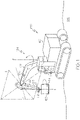
FIG. 1 illustrates an excavator incorporating aspects of the present disclosure; -
FIG. 2A is a schematic display view of an excavating implement of the excavator ofFIG. 1 in a position with respect to a virtual trench and incorporating aspects of the present disclosure; -
FIG. 2B is a schematic display view of an excavating implement of the excavator ofFIG. 1 in a position with respect to a virtual implement bar and a virtual target bar of a design surface and incorporating aspects of the present disclosure -
FIG. 2C is a schematic display view of an excavating implement of the excavator ofFIG. 1 in a first position with respect to a virtual trench and underground features and incorporating aspects of the present disclosure; -
FIG. 3 is a schematic display view of an excavating implement of the excavator ofFIG. 1 in a second position with respect to the virtual trench and underground features and incorporating aspects of the present disclosure; -
FIG. 4 is a schematic display view of an excavating implement of the excavator ofFIG. 1 in a third position with respect to the virtual trench and underground features and incorporating aspects of the present disclosure; -
FIG. 5A is a flow chart illustrating a process that may be implemented by guidance architecture of the excavator ofFIG. 1 to display an augmented reality overlay image according to aspects of the present disclosure; and -
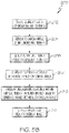
FIG. 5B is a flow chart illustrating another process that may be implemented by guidance architecture of the excavator ofFIG. 1 to display an augmented reality overlay image according to aspects of the present disclosure. - The present disclosure relates to material moving machines configured to execute material moving tasks such as those involving material moving operations. For the purposes of the present disclosure, a material moving machine comprises a material moving implement and is designed to excavate, distribute, smooth, or otherwise move a material using the material moving implement. Examples of such machines include, but are not limited to, excavators, backhoe loaders, dozers, pavers, motor graders, loaders, trenchers, scrapers, drills, crushers, draglines, or any type of machine that includes an implement for moving material. Contemplated materials include, but are not limited to, soil or other surface-based earth materials, subterranean materials, including materials to be mined, and construction aggregates, including, for example, substrate materials and paving materials.
- More particularly, the material moving machines may be excavators including components subject to adaptive control. For example, and not by way of limitation, many types of excavators typically have a hydraulically controlled material moving implement that can be manipulated by a joystick or other means in an operator control station of the machine, and is also subject to partially or fully automated adaptive control. The user of the machine may control the lift, tilt, angle, and pitch of the implement. In addition, one or more of these variables may also be subject to partially or fully automated control based on information sensed or received by an adaptive environmental sensor of the machine.
- In the embodiments described herein, an excavator comprises a display configured to display an augmented reality overlay image including a virtual implement bar, a virtual target bar of a design surface, and/or a virtual trench. In embodiments, the virtual trench comprises underground features. In other embodiments, the virtual trench may not comprise underground features. The virtual trench is adjustably positioned automatically based on a position of an excavating implement. For example, the position of the excavator implement is captured by a camera of the excavator and/or determined through signals from one or more dynamic sensors, as described in greater detail further below. Alternatively or additionally, the virtual trench is adjustably positioned automatically based on rotation of the excavator. Such an augmented reality overlay image may be utilized by an excavator control and/or excavator operator to operate the excavator. For example, with respect to the excavator operator's camera view of a real world, the physical terrain image is augmented by virtual data to present the excavator operator with an augmented reality camera view as the augmented reality overlap image described in greater detail further below.
- In embodiments, the virtual trench may be intended to representative of an actual ditch to be dug. In other embodiments, the virtual trench may not be intended to be representative of an actual ditch to be dug but rather be intended to visualize subsurface features including the design surface in a manner that enables intuitive depth perception by utilizing an operator's understanding of a size and location of the excavating implement. Thus, the virtual trench may be representative of a trench that would be dug if the excavating implement were to dig vertically down from a current location to the design surface and then pull in towards the excavator along the design surface. In some embodiments, the virtual trench has a same width as a leading implement edge of the excavating implement and is disposed with the leading implement edge oriented in a direction towards the center of the excavator. Further, as the excavating implement moves in to or away from the operator and/or as the excavator rotates (i.e., slews), the virtual trench adjustably moves, as described in greater detail further below.
- In embodiments, generation of the virtual trench is at least partially based on terrain surface location to position and display lines representing a top of the virtual trench on a terrain surface, which terrain surface location may be estimated or measured. For example, a roll and pitch of the excavator may be projected to form a plane surface in front of the excavator to utilize as the terrain surface location. Additionally or alternatively, a surface scanner may be used such as a LIDAR, RADAR, or photogrammetry based scanner for such terrain surface location data. Further, GNSS-based vehicle mapping may used to measure the terrain surface as the material moving machine moves around the site (also known as track mapping), the terrain surface may be estimated by measuring the movement of the implement, and/or at least one of terrain data from manual and aerial surveys may be used that is transferred to and stored by the guidance architecture of the excavator.
- Referring initially to
FIG. 1 , anexcavator 100 comprises amachine chassis 102, an excavatinglinkage assembly 104, an excavating implement 114, acamera 124, a display 125, andguidance architecture 106. In embodiments, the guidance architecture comprises control architecture responsive to operator action through manual control of levers and/or linkages and/or responsive to automatic action by a controller of theexcavator 100. The excavatinglinkage assembly 104 comprises anexcavator boom 108 and anexcavator stick 110 that collectively define a plurality of linkage assembly positions. Thecamera 124 is positioned on theexcavator 100 such that a field of view of thecamera 124 encompasses a view of the excavating implement 114 and aterrain 126. - In embodiments, the
excavator 100 comprises a boomdynamic sensor 120, a stickdynamic sensor 122, an implementdynamic sensor 123, or combinations thereof. The boomdynamic sensor 120 is positioned on theexcavator boom 108, the stickdynamic sensor 122 is positioned on theexcavator stick 110, and the implementdynamic sensor 123 is positioned on the excavating implement 114. Thedynamic sensor excavator 100. For example, thedynamic sensor dynamic sensor - The excavating
linkage assembly 104 may be configured to define a linkage assembly heading N̂ and to swing with, or relative to, themachine chassis 102 about a swing axis S of theexcavator 100. Theexcavator stick 110 is configured to curl relative to theexcavator boom 108. For example, theexcavator stick 110 may be configured to curl relative to theexcavator boom 108 about a curl axis C of theexcavator 100. Theexcavator boom 108 andexcavator stick 110 of theexcavator 100 illustrated inFIG. 1 are linked by a simple mechanical coupling that permits movement of theexcavator stick 110 in one degree of rotational freedom relative to theexcavator boom 108. In these types of excavators, the linkage assembly heading N̂ will correspond to the heading of theexcavator boom 108. However, the present disclosure also contemplates the use of excavators equipped with offset booms where theexcavator boom 108 andexcavator stick 110 are linked by a multidirectional coupling that permits movement in more than one rotational degree of freedom. See, for example, the excavator illustrated inUS 7,869,923 ("Slewing Controller, Slewing Control Method, and Construction Machine"). In the case of an excavator with an offset boom, the linkage assembly heading N̂ will correspond to the heading of theexcavator stick 110. - The excavating implement 114 is mechanically coupled to the
excavator stick 110. For example, referring toFIG. 1 , the excavating implement 114 is mechanically coupled to theexcavator stick 110 through an implementcoupling 112. The excavating implement 114 may be mechanically coupled to theexcavator stick 110 via the implementcoupling 112 and configured to rotate about a rotary axis R. In an embodiment, the rotary axis R may be defined by the implementcoupling 112 joining theexcavator stick 110 and the rotary excavating implement 114. In an alternative embodiment, the rotary axis R may be defined by a multidirectional, stick coupling joining theexcavator boom 108 and theexcavator stick 110 along the plane P such that theexcavator stick 110 is configured to rotate about the rotary axis R. Rotation of theexcavator stick 110 about the rotary axis R defined by the stick coupling may result in a corresponding rotation of the rotary excavating implement 114, which is coupled to theexcavator stick 110, about the rotary axis R defined by the stick coupling. - The
guidance architecture 106 comprises one or more dynamic sensors, one or more linkage assembly actuators, and an architecture controller programmed to execute the steps of a control scheme, such as acontrol scheme 190 ofFIG. 5A or acontrol scheme 200 ofFIG. 5B , each of which are described in greater detail further below. Theguidance architecture 106 may comprise a non-transitory computer-readable storage medium, such as memory, comprising machine readable instructions. Theguidance architecture 106 may also comprise a processor communicatively coupled to the non-transitory computer-readable storage medium and configured to execute the machine readable instructions. The one or more linkage assembly actuators facilitate movement of the excavatinglinkage assembly 104. The one or more linkage assembly actuators comprise a hydraulic cylinder actuator, a pneumatic cylinder actuator, an electrical actuator, a mechanical actuator, or combinations thereof. - In embodiments, and referring to
FIG. 2A and acontrol scheme 190 ofFIG. 5A , the architecture controller is programmed to generate an implement image 130 from thecamera 124 instep 192. As an example and not as a limitation, the architecture controller is programmed to capture an implement image as the capture image 130, the implement image comprising the excavating implement 114 and terrain in the working area of the excavating implement 114. The implement image 130 comprises the excavating implement 114 in relation to theterrain 126. The architecture controller is further programmed to generate avirtual trench 132 configured to be disposed as part of theterrain 126 at least partially based on a position of the excavating implement 114 instep 194. In embodiments, the architecture controller may generate a signal indicative of the position and/or orientation of the excavating implement 114 and spacing with respect toterrain 126, as described in greater detail further below, from the one or moredynamic sensors virtual trench 132 superimposed on the implement image 130 to generate an augmented reality overlay image 134 instep 196, and to display the augmented reality overlay image 134 on the display 125 instep 198. As a non-limiting example,FIG. 2A illustrates a view of an augmented reality overlay image 134 including thevirtual trench 132 without underground features. In other embodiments, as illustrated inFIG. 2C , the view of an augmented reality overlay image 134A may be displayed with underground features. The architecture controller may be further programmed to generate the augmented reality overlay image to reveal underground features of the three-dimensional model within thevirtual trench 132 and to occlude underground features of the three-dimensional model outside of thevirtual trench 132. - For example, and referring to
FIGS. 2C-4 , the implement image 130 comprises the excavating implement 114 in relation to theterrain 126 and an augmented reality overlay image 134A, 134B, 134C displays avirtual trench 132 including underground features such aspipes FIG. 2C illustrates a first view of such an augmented reality overlay image 134A. - In embodiments, as illustrated in
FIGS. 2A-2B , the augmented reality overlay image 134, 134' may be displayed without underground features. For example, inFIG. 2B , the augmented reality overlay image 134' is displayed without thevirtual trench 132 or the underground features while displaying a virtual target implementbar 144 and avirtual target bar 146 of adesign surface 150, which are described in greater detail further below. In other embodiments, augmented reality overlay images may be displayed with one or more portions of thevirtual trench 132 while omitting other one or more portions of thevirtual trench 132, For example, a nearest trench boundary of thevirtual trench 132 may be omitted from the display such that thevirtual trench 132 appears to extend under theexcavator 100 and outside of the view of thecamera 124. Sub-visualizations and/or expandable visualizations of such augmented reality overlay images may be displayed, such as a first display as illustrated inFIG. 2C of thevirtual trench 132 including underground features that may be narrowed to a display of thevirtual trench 132 without underground features as displayed inFIG. 2A and/or that may be narrowed to a display of thevirtual target bar 146 without thevirtual trench 132 as displayed inFIG. 2B . Additionally, or alternatively, such displays may be expanded to add components and features as described herein and/or may be displayed in a shared screen space of the display 125. - As illustrated in
FIG. 2C , the first view of an augmented reality overlay image 134A may be displayed with underground features. Referring toFIGS. 2C-4 and thecontrol scheme 200 ofFIG. 5B , the architecture controller is programmed to store geometry data of underground features of theterrain 126 instep 202. In embodiments, alternatively or additionally, the geometry data of underground features may be stored as two-dimensional and/or three-dimensional geometry information. Further, additional underground feature information may be stored by the architecture controller that may or may not match a display of a two-dimensional and/or three-dimensional model. As a non-limiting example, underground feature information of an underground feature, such as a pipe, may include two-dimensional and/or three-dimensional coordinates with respect to the start of the pipe and the end of the pipe. Further, the augmented reality overlay image 134A may include a shaded and/or curved extruded cylinder features to visually represent the pipe inserted between such coordinate points. In additional embodiments, the geometry data of the underground features may include two-dimensional and/or three-dimensional coordinates of end points or corners of the underground features, diameters of the underground features such as pipes or cables, and/or other dimensions such as dimensions of sumps as underground features. - In
step 204 of thecontrol scheme 200 ofFIG. 5B , the architecture controller is programmed to generate an implement image 130 from thecamera 124. As described above, the implement image 130 comprises the excavating implement 114 in relation to theterrain 126. Further, instep 206, the architecture controller is programmed to generate avirtual trench 132 configured to be disposed as part of theterrain 126 at least partially based on the position of the excavating implement 114. For example, the architecture controller may generate a signal indicative of the position and/or orientation of the excavating implement 114 and spacing with respect toterrain 126, as described in greater detail further below, from the one or moredynamic sensors - Further, boundaries of the
virtual trench 132 including one or more walls spaces defined between walls of thevirtual trench 132 are determined such that, instep 208, the architecture controller is programmed to generate a superimposed image of thevirtual trench 132 on the implement image. Insteps virtual trench 132 on the superimposed image to generate an augmented reality overlay image 134A, 134B, 134C, and to display the augmented reality overlay image 134A, 134B, 134C on the display 125. - In embodiments, the underground features displayed in the
virtual trench 132 may be truncated within a wall space defined by thevirtual trench 132. In other embodiments, portions of the underground features beyond the boundaries of thevirtual trench 132 may be displayed in a manner that differentiates such portions from the truncated underground feature portions displayed within the wall space as defined by thevirtual trench 132. As a non-limiting example, an underground feature may include a pipe, and portions of the pipe that are displayed outside of thevirtual trench 132 may include a different color and/or shading from a truncated portion of the pipe displayed within thevirtual trench 132. Such visual differentiation may be indicative of a corresponding positional difference with respect to placement of a portion of the pipe inside thevirtual trench 132 and placement of one or more portions of the pipe disposed outside thevirtual trench 132. - As will be described in greater detail further below,
FIG. 2C illustrates a first view of an augmented reality overlay image 134A. Further,FIG. 3 illustrates a second view of an augmented reality overlay image 134B, andFIG. 4 illustrates a third view of an augmented reality overlay image 134C. Referring toFIGS. 2C-4 , in embodiments, atruncated portion 128 of the underground features is positioned within thevirtual trench 132. Thevirtual trench 132 may be at least based in part on a position and/or orientation of a leading implementedge 140 of the excavating implement 114 in relation to a longitudinally disposedsurface portion 142 of theterrain 126 that is disposed beneath the leading implementedge 140 of the excavating implement 114. - The augmented reality overlay image 134A, 134B, 134C may comprise a virtual implement
bar 144 superimposed over the leading implementedge 140 of the excavating implement 114. The augmented reality overlay image 134A, 134B, 134C may further comprise avirtual target bar 146 superimposed over a bottom-most horizontal portion of afront wall 154 longitudinally extending from the longitudinally disposedsurface portion 142 of theterrain 126 at adepth - The
virtual target bar 146 of thedesign surface 150 may be configured to adjust position in the augmented reality overlay image 134A, 134B, 134C based on a position of the virtual implementbar 144 with respect to theterrain 126 and/or a predetermined depth of cut associated with thedesign surface 150, for example. In embodiments, thedesign surface 150 is indicative of a bottom of thevirtual trench 132 that has a farthest-from-the-viewer boundary at which thevirtual target bar 146 is disposed. Thedesign surface 150 may be a simple plane including a defined slope and/or direction, may include a road design, and/or may include a predetermined depth of cut. -
FIGS. 2C-4 respectively showdifferent bar spacings bar 144 and thevirtual target bar 146 below theterrain 126. For each ofFIGS. 2-4 , a respective bar spacing 160, 170, 180 between the virtual implementbar 144 and thevirtual target bar 146 is scalable with respect to a corresponding real world spacing between the leading implementedge 140 of the excavating implement 114 and a predetermined depth of cut below the longitudinally disposedsurface portion 142 of theterrain 126. Further, a respectiveadjustable length adjustable width virtual target bar 146 is inversely proportional to the respective bar spacing 160, 170, 180. Thus, awidth virtual trench 132 may be adjusted by an amount inversely proportional to the bar spacing, and alength virtual trench 132 may be adjusted by an amount directly proportional to thebar spacing - Further, an
adjustable depth front wall 154 of thevirtual trench 132 is inversely proportional to the respectively bar spacing 160, 170, 180. As an example, and not as a limitation, adepth virtual trench 132 may be adjusted by an amount inversely proportional to abar spacing virtual target bar 146 and the virtual implementbar 144. Thus, the closer the leading implementedge 140 is to theterrain 126 andvirtual target bar 146, as indicated bybar spacings bar 144 and thevirtual target bar 146, the shorter thevirtual trench 132 appears in length with a greater depth and a longer width of thevirtual target bar 146 at a rear portion of thevirtual trench 132 disposed furthest away from a viewer, for example. Alternatively, the farther the leading implementedge 140 is moved from theterrain 126 andvirtual target bar 146, as indicated bybar spacings bar 144 and thevirtual target bar 146, the longer thevirtual trench 132 appears in length with a shorter depth and a shorter width of thevirtual target bar 146. Such visual adjustments may be indicative of changes in viewer perspective due to pixel width changes of the visual image, for example, and are not necessarily indicative of real-world changes in dimensions associated with the components described herein or thevirtual trench 132. - For example, with respect to
FIG. 2C , the augmented reality overlay image 134A includes abar spacing 160, anadjustable length 162 of each of the pair of sidewalls 152A, 152B, and anadjustable width 164 of thevirtual target bar 146. With respect toFIG. 3 , in which the leading implementedge 140 is closer to theterrain 126 than inFIG. 2C , the augmented reality overlay image 134B includes abar spacing 170 that is less than the bar spacing 160 ofFIG. 2C . Additionally,FIG. 3 includes anadjustable length 172 of each of the pair of sidewalls 152A, 152B that is less than theadjustable length 162 ofFIG. 2 , and anadjustable width 174 of thevirtual target bar 146 that greater than theadjustable width 164 ofFIG. 2C . Similarly, inFIG. 4 , in which the leading implementedge 140 is closer to theterrain 126 than inFIGS. 2C-3 , the augmented reality overlay image 134C includes abar spacing 180 that is less than the bar spacing 170 ofFIG. 3 . Further inFIG. 4 , anadjustable length 182 of each of the pair of sidewalls 152A, 152B that is less than theadjustable length 174 ofFIG. 3 , and anadjustable width 184 of thevirtual target bar 146 that greater than theadjustable width 174 ofFIG. 3 . Thus, in each of augmented reality overlay images 134A, 134B, 134C, as the virtual implementbar 144 moves closer to thevirtual target bar 146 on theterrain 126, the dynamically adjustable views of thevirtual trench 132 change to display a shortenedadjustable length adjustable depth front wall 154, and a greateradjustable width virtual target bar 146. The architecture controller and/or an excavator operator may set a range of dimensions for display with respect to thevirtual trench 132 as described herein. For the purposes of enhancing clarity in a 3D visualization of thevirtual trench 132, for example, while thevirtual trench 132 may appear to have an increased depth visually as the virtual implementbar 144 moves closer to thevirtual target bar 146 on theterrain 126, a corresponding real-world depth illustrating underground features (as described in greater detail further below) in thevirtual trench 132 may remain the same. As a non-limiting example, even though adepth 163 of thefront wall 154 inFIG. 2C visually appears to be less than a depth 183 of thefront wall 154 inFIG. 4 , each ofFIGS. 2-4 may correspond to a real-world depth of 5 feet from theterrain 126 to thevirtual target bar 146. With respect to such examples, underground features within 5 feet from a surface of theterrain 126 are displayed, such as through illustrations as shown inFIGS. 2-4 . - In embodiments, the
virtual target bar 146 comprises a bottom-most portion of thefront wall 154 of thevirtual trench 132. Thevirtual trench 132 comprises adesign surface 150 disposed beneath the longitudinally disposedsurface portion 142 at adepth design surface 150 disposed therebetween, and thefront wall 154 disposed between the pair of sidewalls 152A, 152B and defining at the bottom-most portion thevirtual target bar 146. Theadjustable width virtual target bar 146 equals a width of thefront wall 154 of thevirtual trench 132. Boundaries of thevirtual trench 132 including thedesign surface 150, the pair of sidewalls 152A, 152B, and thefront wall 154 of thevirtual trench 132 may be depicted as dashedlines 148 in the augmented reality overlay image 134A, 134B, 134C. In embodiments, thevirtual target bar 146 at a bottom boundary of thefront wall 154 may be depicted as a solid and/or bolded line. Thevirtual trench 132, including thevirtual target bar 146 and the boundaries of thevirtual trench 132, is configured to be dynamically adjusted and dynamically displayed based on the position and/or orientation of the virtual implementbar 144. - In an embodiment, with respect to a display of and within the augmented reality overlay image 134A, 134B, 134C, the virtual implement
bar 144 comprises a solid red line. Further, thevirtual target bar 146 may comprise a solid green line. Thevirtual trench 132 may be defined by a plurality of dashedlines 148 that are red in color or other suitable highlighting and differentiating color. It should be understood that other colors for such displayable components are within the scope of this disclosure. - In embodiments, and within the
virtual trench 132, underground features are displayed that adjust along with the dynamic adjustment of thevirtual trench 132 in the augmented reality overlay images 134A, 134B, 134C and that are truncated at walls of thevirtual trench 132 to enable enhanced depth perception. The underground features may comprise, for example, portions of pipes and/or cables or like underground components truncated to be defined and positioned with the boundaries of thevirtual trench 132 at least partially based on the stored geometry data of underground features. To further enhance depth perception, display of the underground features may be indicative of a spacing and/or distance of the underground features with respect to the wall boundaries of thevirtual trench 132. For example, inFIG. 2C , apipe 190 is displayed as nearer a surface of theterrain 126 than apipe 192, while thepipe 192 is displayed as distanced farther from the surface of theterrain 126 and closer to thedesign surface 150. In embodiments, thevirtual trench 132 may be displayed as described herein without a display of underground features. - The underground features may comprise at least one of a
pipe 190 and cable disposed below the terrain. Thevirtual trench 132 may comprise at least a portion of the at least one of apipe 190 and cable in the augmented reality overlay image 134A, 134B, 134C. In embodiments, the underground features comprise at least a pair ofpipes terrain 126. Afirst pipe 190 of the pair ofpipes second pipe 192 of the pair ofpipes FIG. 2C . For example, thefirst pipe 190 of the pair ofpipes second pipe 192 of the pair ofpipes pipes pipe 190 inFIG. 2C , may be disposed at an intersecting angle with respect to thefront wall 154 of thevirtual trench 132. The display of this angle may change depending on the display of the dimensions of thevirtual trench 132 in the augmented reality overlay image 134A, 134B, 134C. Further, thevirtual trench 132 may comprise at least a portion of each of the pair ofpipes Fig. 2C , in which each of the pair ofpipes pipes pipe 190, may comprise a yellow color, and the other pipe of the pair ofpipes pipe 192, may comprise a green color. - It is contemplated that the embodiments of the present disclosure may assist to provide a more efficient method of excavation planning on site in a manner that minimizes a risk of human error in planning an excavation. For example, the embodiments described herein may assist to minimize a risk of human error in estimating and/or being aware of a positioning of underground features when excavating in real-time. The controller of the excavator or other control technologies may be improved with such augmented reality overlay images as described herein such that processing systems in connection with the augmented reality overlay images are enhanced and improved with respect to efficiency, speed, safety, production, and accuracy.
- A signal may be "generated" by direct or indirect calculation or measurement, with or without the aid of a sensor.
- For the purposes of describing and defining the present invention, it is noted that reference herein to a variable being "based on" a parameter or another variable is not intended to denote that the variable is exclusively based on the listed parameter or variable. Rather, reference herein to a variable that is "based on" a listed parameter is intended to be open ended such that the variable may be based on a single parameter or a plurality of parameters.
Claims (15)
- A material moving machine (100) comprising:a material moving implement (104);a camera (124) positioned on the material moving machine (100) and comprising a field of view that encompasses the material moving implement and terrain in a working area of the material moving implement;an augmented display (125); anda control architecture comprising one or more dynamic sensors (120, 122, 123) configured to generate a position signal representing a position of the material moving implement (100), characterised by the control architecture further comprising an architecture controller comprising a memory and an image generator communicatively coupled to the augmented display (125), the architecture controller programmed tostore in the memory a three-dimensional model of underground features of the terrain,capture an implement image (130) by the camera (124), the implement image (130) comprising the material moving implement (104) and terrain in the working area of the material moving implement,generate through the image generator a superimposed image by superimposing corresponding portions of the implement image and the three-dimensional model of underground features,generate a virtual trench (132) based on the position of the material moving implement,overlay the virtual trench (132) on the superimposed image to generate an augmented reality overlay image (134) comprising the virtual trench (132) and the superimposed portions of the implement image (130) and the three-dimensional model of underground features,generate through the image generator the augmented reality overlay image (134), anddisplay the augmented reality overlay image on the augmented display (125).
- The material moving machine of claim 1, wherein the architecture controller is programmed to: generate the augmented reality overlay image (134) to reveal underground features of the three-dimensional model within the virtual trench (132) and to occlude underground features of the three-dimensional model outside of the virtual trench (132); generate the virtual trench (132) based on a position of a leading implement edge (140) of the material moving implement (100) in relation to a longitudinally disposed surface portion of the terrain disposed beneath the leading implement edge (140) of the material moving implement (100), and generate the augmented reality overlay image (134) to comprise:a virtual implement bar (144) superimposed over the leading implement edge (140) of the material moving implement (100); anda virtual target bar (146) superimposed over the longitudinally disposed surface portion of the terrain and configured to adjust position in the augmented reality overlay image (134) based on a position of the virtual implement bar (144) with respect to the virtual target bar (146) on the terrain.
- The material moving machine of claim 2, wherein:the virtual implement bar (144) comprises a solid red line;the virtual target bar (146) comprises a bottom-most portion of the virtual trench as a solid green line; andthe virtual trench (132) is defined by a plurality of dashed red lines.
- The material moving machine of claim 2, wherein the architecture controller is programmed to generate the virtual trench (132) such that the virtual target bar (146) comprises a bottom-most portion of the virtual trench (132) and the virtual trench comprises:an underground surface;a pair of sidewalls disposed between the underground surface; anda front wall disposed between the pair of sidewalls and below the virtual target bar (146).
- The material moving machine of claim 4, wherein the architecture controller is programmed to generate:a bar spacing between the virtual implement bar (144) and the virtual target bar (146) that is scalable with respect to a corresponding real world spacing with the leading implement edge (140) of the material moving implement (100) and the longitudinally disposed surface portion of the terrain;an adjustable width of the virtual target bar (146) that is inversely proportional to the bar spacing; andan adjustable length of the pair of sidewalls that is directly proportional to the bar spacing.
- The material moving machine of claim 5, wherein the adjustable width of the virtual target bar (146) equals a width of the front wall of the virtual trench (132).
- The material moving machine of claim 4, wherein the architecture controller is programmed to depict boundaries of the underground surface, the pair of sidewalls, and the front wall of the virtual trench (132) as dashed lines in the augmented reality overlay image (134).
- The material moving machine of claim 1, wherein the architecture controller is programmed to dispose at least a pair of pipes (190, 192) comprising the underground features below the terrain.
- The material moving machine of claim 8, wherein the architecture controller is programmed to dispose a first pipe (190) of the pair of pipes above and at angle to a second pipe (192) of the pair of pipes.
- The material moving machine of claim 9, wherein the architecture controller is programmed to dispose the first pipe (190) of the pair of pipes perpendicular to the second pipe (192) of the pair of pipes.
- The material moving machine of claim 10, wherein the architecture controller is programmed to:generate the virtual trench (132) to comprise at least a portion of each of the pair of pipes (190, 192) in the augmented reality overlay image (134);display each of the pair of pipes (190, 192) with a different color with respect to one another; or programmed to:generate the virtual trench (132) to comprise a front wall; anddispose one pipe of the pair of pipes (190, 192) an intersecting angle with respect to the front wall of the virtual trench (132).
- The material moving machine of claim 1, wherein:the material moving machine is an excavator (100) comprising a machine chassis (102) and an excavating linkage assembly (104);the excavating linkage assembly (104) comprises an excavator boom (108) and an excavator stick (110) that collectively define a plurality of linkage assembly positions;the excavating linkage assembly (104) is configured to swing with, or relative to, the machine chassis (102);the excavator stick (110) is configured to curl relative to the excavator boom (108);the material moving implement is an excavating implement (114) mechanically coupled to the excavator stick (110); andthe control architecture comprises one or more linkage assembly actuators configured to actuate the excavating linkage assembly (104) through the plurality of linkage assembly positions.
- The material moving machine of claim 1, wherein the material moving machine is an excavator (100) comprising:a machine chassis (102);an excavating implement (114) as the material moving implement;an excavating linkage assembly (104) comprising an excavator boom (108) and an excavator stick (110) that collectively define a plurality of linkage assembly positions, wherein the excavating linkage assembly (104) is configured to swing with, or relative to, the machine chassis (102),the excavator stick (110) is configured to curl relative to the excavator boom (108), and the excavating implement is mechanically coupled to the excavator stick (110);the camera (124) positioned on the excavator and comprising the field of view that encompasses the excavating implement (114) and terrain in the working area of the excavating implement (114); andcontrol architecture comprising one or more dynamic sensors (120, 122, 123) configured to generate the position signal representing the position of the material moving implement comprising the excavating implement (114), one or more linkage assembly actuators configured to actuate the excavating linkage assembly (104) through the plurality of linkage assembly positions, and the architecture controller comprising the memory and the image generator communicatively coupled to the augmented display (125), the architecture controller programmed tostore in the memory a three-dimensional model of underground features of the terrain,capture an implement image (130) by the camera (124), the implement image (130) comprising the excavating implement and terrain in the working area of the excavating implement,generate through the image generator a superimposed image by superimposing corresponding portions of the implement image (130) and the three-dimensional model of underground features,generate a virtual trench (132) based on a position of a leading implement edge (140) of the excavating implement in relation to a longitudinally disposed surface portion of the terrain disposed beneath the leading implement edge (140),overlay the virtual trench (132) on the superimposed image to generate through the image generator an augmented reality overlay image comprising the virtual trench (132) and the superimposed portions of the implement image (130) and the three-dimensional model of underground features, wherein a virtual implement bar (144) is superimposed over a leading implement edge (140) of the excavating implement, and a virtual target bar (146) is superimposed over a longitudinally disposed surface portion of the terrain,adjust the virtual trench (132) based on a position of the virtual implement bar (144) with respect to the virtual target bar (146) on the terrain, anddisplay the augmented reality overlay image on the augmented display (125).
- A method of operating a material moving machine utilizing an augmented display comprising:disposing the material moving machine on terrain, the material moving machine comprising a material moving implement (104), a camera (124), the augmented display (125), and control architecture, wherein(i) the camera (124) is positioned on the excavator and comprises a field of view that encompasses the material moving implement (104) and terrain in a working area of the material moving implement (104), and(ii) the control architecture comprises one or more dynamic sensors (120, 122, 123) configured to generate a position signal representing a position of the material moving implement (104), a memory, and an image generator communicatively coupled to the augmented display (125);storing in the memory a three-dimensional model of underground features of the terrain;capturing an implement image (130) by the camera (124), the implement image (130) comprising the material moving implement (104) and terrain in the working area of the material moving implement (104);generating through the image generator a superimposed image by superimposing corresponding portions of the implement image (130) and the three-dimensional model of underground features;generating a virtual trench (132) based on the position of the material moving implement (104);overlaying the virtual trench (132) on the superimposed image to generate an augmented reality overlay image (134) comprising the virtual trench (132) and the superimposed portions of the implement image (130) and the three-dimensional model of underground features;generating through the image generator the augmented reality overlay image (134);displaying the augmented reality overlay image (134) on the augmented display (125);operating the material moving machine utilizing the control architecture to move the material moving implement (104) with respect to the terrain based on the augmented reality overlay image (134);generating the virtual trench (132) based on a position of a leading implement edge (140) of the material moving implement (104) in relation to a longitudinally disposed surface portion of the terrain disposed beneath the leading implement edge (140); andgenerating the augmented reality overlay image (134) comprising a virtual implement bar (144) superimposed of a leading implement edge (140) of the material moving implement (104), and virtual target bar (146) superimposed over a longitudinally disposed surface portion of the terrain.
- The method of claim 14, further comprising:adjusting a position of the virtual target bar (146) in the augmented reality overlay image (134) based on a position of the virtual implement bar (144) with respect to the virtual target bar (146) on the terrain,adjusting a depth of the virtual trench (132) by an amount inversely proportional to a bar spacing between the virtual target bar (146) and the virtual implement bar (144);adjusting a width of the virtual trench (132) by an amount inversely proportional to the bar spacing; andadjusting a length of sidewalls of the virtual trench (132) by an amount directly proportional to the bar spacing.
Applications Claiming Priority (2)
| Application Number | Priority Date | Filing Date | Title |
|---|---|---|---|
| US201762466542P | 2017-03-03 | 2017-03-03 | |
| PCT/US2018/020579 WO2018160921A1 (en) | 2017-03-03 | 2018-03-02 | Augmented reality display for material moving machines |
Publications (3)
| Publication Number | Publication Date |
|---|---|
| EP3590094A1 EP3590094A1 (en) | 2020-01-08 |
| EP3590094A4 EP3590094A4 (en) | 2020-12-16 |
| EP3590094B1 true EP3590094B1 (en) | 2022-05-04 |
Family
ID=63357286
Family Applications (1)
| Application Number | Title | Priority Date | Filing Date |
|---|---|---|---|
| EP18760630.6A Active EP3590094B1 (en) | 2017-03-03 | 2018-03-02 | Augmented reality display for material moving machines |
Country Status (5)
| Country | Link |
|---|---|
| US (2) | US10301798B2 (en) |
| EP (1) | EP3590094B1 (en) |
| JP (1) | JP7133562B2 (en) |
| AU (1) | AU2018227862B9 (en) |
| WO (1) | WO2018160921A1 (en) |
Families Citing this family (31)
| Publication number | Priority date | Publication date | Assignee | Title |
|---|---|---|---|---|
| US9235763B2 (en) | 2012-11-26 | 2016-01-12 | Trimble Navigation Limited | Integrated aerial photogrammetry surveys |
| JP6480830B2 (en) * | 2015-08-24 | 2019-03-13 | 株式会社小松製作所 | Wheel loader control system, control method therefor, and wheel loader control method |
| KR102463068B1 (en) * | 2016-09-30 | 2022-11-02 | 스미토모 겐키 가부시키가이샤 | shovel |
| JP6434476B2 (en) * | 2016-12-06 | 2018-12-05 | ファナック株式会社 | Augmented reality simulation apparatus and augmented reality simulation program |
| EP3275831B1 (en) * | 2017-06-16 | 2019-12-18 | ABB Schweiz AG | Modified video stream for supporting remote control of a container crane |
| NO344567B1 (en) * | 2018-04-12 | 2020-02-03 | Geonord As | Construction machine guidance system |
| JP7080750B2 (en) * | 2018-06-29 | 2022-06-06 | 株式会社小松製作所 | Display control system, remote control system, display control device, and display control method |
| US10755484B1 (en) * | 2018-08-17 | 2020-08-25 | Bentley Systems, Incorporated | Estimating subsurface feature locations during excavation |
| US10755483B1 (en) * | 2018-08-17 | 2020-08-25 | Bentley Systems, Incorporated | Techniques for accurate and faithful projections in an outdoor augmented reality view |
| US10699488B1 (en) * | 2018-09-07 | 2020-06-30 | Facebook Technologies, Llc | System and method for generating realistic augmented reality content |
| JP7201486B2 (en) * | 2019-03-13 | 2023-01-10 | 日立建機株式会社 | working machine |
| DE102019207151A1 (en) * | 2019-05-16 | 2020-11-19 | Robert Bosch Gmbh | Method for analyzing the nature of the soil and / or the degree of hardness of the soil |
| EP3748583A1 (en) | 2019-06-04 | 2020-12-09 | My Virtual Reality Software AS | Subsurface utility visualization |
| JP7024926B2 (en) * | 2019-09-27 | 2022-02-24 | 株式会社タダノ | Crane information display system |
| CN110805080B (en) * | 2019-10-16 | 2022-08-19 | 广西弘德茂机械有限公司 | Personnel safety protection system of loader operation place |
| US10943360B1 (en) * | 2019-10-24 | 2021-03-09 | Trimble Inc. | Photogrammetric machine measure up |
| KR102399227B1 (en) * | 2019-12-30 | 2022-05-17 | 주식회사 지오멕스소프트 | Managing system of underground facilities using gpr detector |
| EP3865982B1 (en) | 2020-02-17 | 2024-04-17 | Hexagon Technology Center GmbH | Augmented viewing of a scenery and subsurface infrastructure |
| US11692319B2 (en) * | 2020-03-25 | 2023-07-04 | Caterpillar Paving Products Inc. | Dynamic image augmentation for milling machine |
| US12031300B2 (en) * | 2020-11-05 | 2024-07-09 | Trimble Inc. | High-accuracy augmented reality display for construction machines |
| EP4256271A4 (en) * | 2020-12-01 | 2024-11-20 | Clearedge3d, Inc. | SYSTEM, METHOD AND COMPUTER PROGRAM PRODUCT FOR CONSTRUCTION INSPECTION |
| JP7552494B2 (en) * | 2021-05-10 | 2024-09-18 | コベルコ建機株式会社 | Construction support system and construction support method |
| WO2022255995A1 (en) * | 2021-06-02 | 2022-12-08 | Vertechs Energy Solutions Llc | Augmented reality drilling, completion and production visualization system and synergy method based on holographic projection |
| US12006655B2 (en) * | 2021-08-02 | 2024-06-11 | Deere & Company | Ground engaging tool contact detection system and method |
| US20230141588A1 (en) * | 2021-11-11 | 2023-05-11 | Caterpillar Paving Products Inc. | System and method for configuring augmented reality on a worksite |
| JP7811484B2 (en) * | 2022-02-18 | 2026-02-05 | 日立建機株式会社 | Display control device and remote control device |
| JP7836619B2 (en) * | 2022-05-23 | 2026-03-27 | 日立建機株式会社 | Remote control system, remotely operated work machine system, and work information display control method |
| US12505675B2 (en) | 2022-06-28 | 2025-12-23 | Trimble Inc. | Automatic optimization of obstacle detection |
| US11949845B2 (en) | 2022-08-31 | 2024-04-02 | Caterpillar Inc. | Dynamic visual overlay for enhanced terrain perception on remote control construction equipment |
| JP2024093731A (en) * | 2022-12-27 | 2024-07-09 | 住友重機械工業株式会社 | Display device for work machine and work machine |
| US12509859B2 (en) | 2023-01-26 | 2025-12-30 | Deere & Company | Terrain measurement for automation control and productivity tracking of work machine |
Family Cites Families (18)
| Publication number | Priority date | Publication date | Assignee | Title |
|---|---|---|---|---|
| US6282477B1 (en) | 2000-03-09 | 2001-08-28 | Caterpillar Inc. | Method and apparatus for displaying an object at an earthworking site |
| US6735888B2 (en) | 2001-05-18 | 2004-05-18 | Witten Technologies Inc. | Virtual camera on the bucket of an excavator displaying 3D images of buried pipes |
| US20060034535A1 (en) | 2004-08-10 | 2006-02-16 | Koch Roger D | Method and apparatus for enhancing visibility to a machine operator |
| US20080000111A1 (en) | 2006-06-29 | 2008-01-03 | Francisco Roberto Green | Excavator control system and method |
| US20080047170A1 (en) | 2006-08-24 | 2008-02-28 | Trimble Navigation Ltd. | Excavator 3D integrated laser and radio positioning guidance system |
| US8139108B2 (en) | 2007-01-31 | 2012-03-20 | Caterpillar Inc. | Simulation system implementing real-time machine data |
| US8817238B2 (en) | 2007-10-26 | 2014-08-26 | Deere & Company | Three dimensional feature location from an excavator |
| US20130054097A1 (en) * | 2011-08-22 | 2013-02-28 | Deere And Company | Buried Utility Data with Exclusion Zones |
| US8689471B2 (en) * | 2012-06-19 | 2014-04-08 | Caterpillar Trimble Control Technologies Llc | Method and system for controlling an excavator |
| US8965642B2 (en) * | 2012-10-05 | 2015-02-24 | Komatsu Ltd. | Display system of excavating machine and excavating machine |
| US8918246B2 (en) * | 2012-12-27 | 2014-12-23 | Caterpillar Inc. | Augmented reality implement control |
| JP6258582B2 (en) | 2012-12-28 | 2018-01-10 | 株式会社小松製作所 | Construction machine display system and control method thereof |
| US20150199106A1 (en) | 2014-01-14 | 2015-07-16 | Caterpillar Inc. | Augmented Reality Display System |
| JP6232494B2 (en) * | 2014-04-23 | 2017-11-15 | 株式会社日立製作所 | Drilling rig |
| US9428885B2 (en) * | 2014-09-15 | 2016-08-30 | Trimble Navigation Limited | Guidance system for earthmoving machinery |
| US9824490B1 (en) * | 2015-06-08 | 2017-11-21 | Bentley Systems, Incorporated | Augmentation of a dynamic terrain surface |
| DE102015221356B4 (en) * | 2015-10-30 | 2020-12-24 | Conti Temic Microelectronic Gmbh | Device and method for providing a vehicle panoramic view |
| WO2017176773A1 (en) * | 2016-04-08 | 2017-10-12 | Ace/Avant Concrete Construction Co., Inc. | Excavation measurement |
-
2018
- 2018-03-02 WO PCT/US2018/020579 patent/WO2018160921A1/en not_active Ceased
- 2018-03-02 AU AU2018227862A patent/AU2018227862B9/en active Active
- 2018-03-02 JP JP2019547684A patent/JP7133562B2/en active Active
- 2018-03-02 EP EP18760630.6A patent/EP3590094B1/en active Active
- 2018-03-02 US US15/910,121 patent/US10301798B2/en active Active
-
2019
- 2019-04-05 US US16/376,126 patent/US10550549B2/en active Active
Also Published As
| Publication number | Publication date |
|---|---|
| US10550549B2 (en) | 2020-02-04 |
| WO2018160921A1 (en) | 2018-09-07 |
| JP2020509272A (en) | 2020-03-26 |
| AU2018227862A1 (en) | 2019-10-10 |
| EP3590094A4 (en) | 2020-12-16 |
| US20180251961A1 (en) | 2018-09-06 |
| AU2018227862B2 (en) | 2022-11-17 |
| US20190249398A1 (en) | 2019-08-15 |
| US10301798B2 (en) | 2019-05-28 |
| EP3590094A1 (en) | 2020-01-08 |
| AU2018227862B9 (en) | 2022-11-24 |
| JP7133562B2 (en) | 2022-09-08 |
Similar Documents
| Publication | Publication Date | Title |
|---|---|---|
| EP3590094B1 (en) | Augmented reality display for material moving machines | |
| AU2022209235B2 (en) | Display control device and display control method | |
| CN109757114B (en) | Display control device for working machine, and display control method for working machine | |
| AU2019292457B2 (en) | Display control device, display control system, and display control method | |
| KR101695914B1 (en) | Excavator 3-dimensional earthwork bim system for providing realtime shape information of excavator in executing earthwork construction | |
| EP3235960B1 (en) | Controller and method for determining wear of a component of a shovel | |
| JP6918716B2 (en) | Construction machinery | |
| WO2017061518A1 (en) | Construction management system, construction management method and management device | |
| JP7080750B2 (en) | Display control system, remote control system, display control device, and display control method | |
| JPWO2019175917A1 (en) | Work machine | |
| CN116249815A (en) | automatic operating system | |
| JP7636598B2 (en) | Display control device and display method | |
| JP6928740B2 (en) | Construction management system, work machine, and construction management method | |
| JP6815462B2 (en) | Shape measurement system and shape measurement method | |
| JP6616149B2 (en) | Construction method, work machine control system, and work machine | |
| US20240060275A1 (en) | Method and system of configuring a machine control unit of a construction machine | |
| AU2021352215B2 (en) | Display control device and display control method | |
| JP2021059970A (en) | Construction management system | |
| DE102025135808A1 (en) | Computer-implemented method for the visual representation of underground objects of interest and systems using such a method | |
| AU2025230823A1 (en) | System and method for visually representing subterranean objects of interest in a field of view display for a work area | |
| WO2026094459A1 (en) | Display control system, remote operation system, and display control method | |
| WO2025204383A1 (en) | Work machine display system |
Legal Events
| Date | Code | Title | Description |
|---|---|---|---|
| STAA | Information on the status of an ep patent application or granted ep patent |
Free format text: STATUS: THE INTERNATIONAL PUBLICATION HAS BEEN MADE |
|
| PUAI | Public reference made under article 153(3) epc to a published international application that has entered the european phase |
Free format text: ORIGINAL CODE: 0009012 |
|
| STAA | Information on the status of an ep patent application or granted ep patent |
Free format text: STATUS: REQUEST FOR EXAMINATION WAS MADE |
|
| 17P | Request for examination filed |
Effective date: 20190918 |
|
| AK | Designated contracting states |
Kind code of ref document: A1 Designated state(s): AL AT BE BG CH CY CZ DE DK EE ES FI FR GB GR HR HU IE IS IT LI LT LU LV MC MK MT NL NO PL PT RO RS SE SI SK SM TR |
|
| AX | Request for extension of the european patent |
Extension state: BA ME |
|
| DAV | Request for validation of the european patent (deleted) | ||
| DAX | Request for extension of the european patent (deleted) | ||
| A4 | Supplementary search report drawn up and despatched |
Effective date: 20201118 |
|
| RIC1 | Information provided on ipc code assigned before grant |
Ipc: G06T 11/00 20060101ALI20201112BHEP Ipc: E02F 9/24 20060101AFI20201112BHEP Ipc: G09G 5/377 20060101ALI20201112BHEP Ipc: E02F 9/26 20060101ALI20201112BHEP |
|
| REG | Reference to a national code |
Ref country code: DE Ref legal event code: R079 Ref document number: 602018034973 Country of ref document: DE Free format text: PREVIOUS MAIN CLASS: G06T0011000000 Ipc: E02F0009200000 |
|
| GRAP | Despatch of communication of intention to grant a patent |
Free format text: ORIGINAL CODE: EPIDOSNIGR1 |
|
| STAA | Information on the status of an ep patent application or granted ep patent |
Free format text: STATUS: GRANT OF PATENT IS INTENDED |
|
| RIC1 | Information provided on ipc code assigned before grant |
Ipc: E02F 9/20 20060101AFI20211014BHEP |
|
| INTG | Intention to grant announced |
Effective date: 20211105 |
|
| GRAS | Grant fee paid |
Free format text: ORIGINAL CODE: EPIDOSNIGR3 |
|
| GRAA | (expected) grant |
Free format text: ORIGINAL CODE: 0009210 |
|
| STAA | Information on the status of an ep patent application or granted ep patent |
Free format text: STATUS: THE PATENT HAS BEEN GRANTED |
|
| AK | Designated contracting states |
Kind code of ref document: B1 Designated state(s): AL AT BE BG CH CY CZ DE DK EE ES FI FR GB GR HR HU IE IS IT LI LT LU LV MC MK MT NL NO PL PT RO RS SE SI SK SM TR |
|
| REG | Reference to a national code |
Ref country code: GB Ref legal event code: FG4D |
|
| REG | Reference to a national code |
Ref country code: CH Ref legal event code: EP |
|
| REG | Reference to a national code |
Ref country code: AT Ref legal event code: REF Ref document number: 1489170 Country of ref document: AT Kind code of ref document: T Effective date: 20220515 |
|
| REG | Reference to a national code |
Ref country code: DE Ref legal event code: R096 Ref document number: 602018034973 Country of ref document: DE |
|
| REG | Reference to a national code |
Ref country code: IE Ref legal event code: FG4D |
|
| REG | Reference to a national code |
Ref country code: LT Ref legal event code: MG9D |
|
| REG | Reference to a national code |
Ref country code: NL Ref legal event code: MP Effective date: 20220504 |
|
| REG | Reference to a national code |
Ref country code: AT Ref legal event code: MK05 Ref document number: 1489170 Country of ref document: AT Kind code of ref document: T Effective date: 20220504 |
|
| PG25 | Lapsed in a contracting state [announced via postgrant information from national office to epo] |
Ref country code: SE Free format text: LAPSE BECAUSE OF FAILURE TO SUBMIT A TRANSLATION OF THE DESCRIPTION OR TO PAY THE FEE WITHIN THE PRESCRIBED TIME-LIMIT Effective date: 20220504 Ref country code: PT Free format text: LAPSE BECAUSE OF FAILURE TO SUBMIT A TRANSLATION OF THE DESCRIPTION OR TO PAY THE FEE WITHIN THE PRESCRIBED TIME-LIMIT Effective date: 20220905 Ref country code: NO Free format text: LAPSE BECAUSE OF FAILURE TO SUBMIT A TRANSLATION OF THE DESCRIPTION OR TO PAY THE FEE WITHIN THE PRESCRIBED TIME-LIMIT Effective date: 20220804 Ref country code: NL Free format text: LAPSE BECAUSE OF FAILURE TO SUBMIT A TRANSLATION OF THE DESCRIPTION OR TO PAY THE FEE WITHIN THE PRESCRIBED TIME-LIMIT Effective date: 20220504 Ref country code: LT Free format text: LAPSE BECAUSE OF FAILURE TO SUBMIT A TRANSLATION OF THE DESCRIPTION OR TO PAY THE FEE WITHIN THE PRESCRIBED TIME-LIMIT Effective date: 20220504 Ref country code: HR Free format text: LAPSE BECAUSE OF FAILURE TO SUBMIT A TRANSLATION OF THE DESCRIPTION OR TO PAY THE FEE WITHIN THE PRESCRIBED TIME-LIMIT Effective date: 20220504 Ref country code: GR Free format text: LAPSE BECAUSE OF FAILURE TO SUBMIT A TRANSLATION OF THE DESCRIPTION OR TO PAY THE FEE WITHIN THE PRESCRIBED TIME-LIMIT Effective date: 20220805 Ref country code: FI Free format text: LAPSE BECAUSE OF FAILURE TO SUBMIT A TRANSLATION OF THE DESCRIPTION OR TO PAY THE FEE WITHIN THE PRESCRIBED TIME-LIMIT Effective date: 20220504 Ref country code: ES Free format text: LAPSE BECAUSE OF FAILURE TO SUBMIT A TRANSLATION OF THE DESCRIPTION OR TO PAY THE FEE WITHIN THE PRESCRIBED TIME-LIMIT Effective date: 20220504 Ref country code: BG Free format text: LAPSE BECAUSE OF FAILURE TO SUBMIT A TRANSLATION OF THE DESCRIPTION OR TO PAY THE FEE WITHIN THE PRESCRIBED TIME-LIMIT Effective date: 20220804 Ref country code: AT Free format text: LAPSE BECAUSE OF FAILURE TO SUBMIT A TRANSLATION OF THE DESCRIPTION OR TO PAY THE FEE WITHIN THE PRESCRIBED TIME-LIMIT Effective date: 20220504 |
|
| PG25 | Lapsed in a contracting state [announced via postgrant information from national office to epo] |
Ref country code: RS Free format text: LAPSE BECAUSE OF FAILURE TO SUBMIT A TRANSLATION OF THE DESCRIPTION OR TO PAY THE FEE WITHIN THE PRESCRIBED TIME-LIMIT Effective date: 20220504 Ref country code: PL Free format text: LAPSE BECAUSE OF FAILURE TO SUBMIT A TRANSLATION OF THE DESCRIPTION OR TO PAY THE FEE WITHIN THE PRESCRIBED TIME-LIMIT Effective date: 20220504 Ref country code: LV Free format text: LAPSE BECAUSE OF FAILURE TO SUBMIT A TRANSLATION OF THE DESCRIPTION OR TO PAY THE FEE WITHIN THE PRESCRIBED TIME-LIMIT Effective date: 20220504 Ref country code: IS Free format text: LAPSE BECAUSE OF FAILURE TO SUBMIT A TRANSLATION OF THE DESCRIPTION OR TO PAY THE FEE WITHIN THE PRESCRIBED TIME-LIMIT Effective date: 20220904 |
|
| PG25 | Lapsed in a contracting state [announced via postgrant information from national office to epo] |
Ref country code: SM Free format text: LAPSE BECAUSE OF FAILURE TO SUBMIT A TRANSLATION OF THE DESCRIPTION OR TO PAY THE FEE WITHIN THE PRESCRIBED TIME-LIMIT Effective date: 20220504 Ref country code: SK Free format text: LAPSE BECAUSE OF FAILURE TO SUBMIT A TRANSLATION OF THE DESCRIPTION OR TO PAY THE FEE WITHIN THE PRESCRIBED TIME-LIMIT Effective date: 20220504 Ref country code: RO Free format text: LAPSE BECAUSE OF FAILURE TO SUBMIT A TRANSLATION OF THE DESCRIPTION OR TO PAY THE FEE WITHIN THE PRESCRIBED TIME-LIMIT Effective date: 20220504 Ref country code: EE Free format text: LAPSE BECAUSE OF FAILURE TO SUBMIT A TRANSLATION OF THE DESCRIPTION OR TO PAY THE FEE WITHIN THE PRESCRIBED TIME-LIMIT Effective date: 20220504 Ref country code: DK Free format text: LAPSE BECAUSE OF FAILURE TO SUBMIT A TRANSLATION OF THE DESCRIPTION OR TO PAY THE FEE WITHIN THE PRESCRIBED TIME-LIMIT Effective date: 20220504 Ref country code: CZ Free format text: LAPSE BECAUSE OF FAILURE TO SUBMIT A TRANSLATION OF THE DESCRIPTION OR TO PAY THE FEE WITHIN THE PRESCRIBED TIME-LIMIT Effective date: 20220504 |
|
| REG | Reference to a national code |
Ref country code: DE Ref legal event code: R097 Ref document number: 602018034973 Country of ref document: DE |
|
| PLBE | No opposition filed within time limit |
Free format text: ORIGINAL CODE: 0009261 |
|
| STAA | Information on the status of an ep patent application or granted ep patent |
Free format text: STATUS: NO OPPOSITION FILED WITHIN TIME LIMIT |
|
| PG25 | Lapsed in a contracting state [announced via postgrant information from national office to epo] |
Ref country code: AL Free format text: LAPSE BECAUSE OF FAILURE TO SUBMIT A TRANSLATION OF THE DESCRIPTION OR TO PAY THE FEE WITHIN THE PRESCRIBED TIME-LIMIT Effective date: 20220504 |
|
| 26N | No opposition filed |
Effective date: 20230207 |
|
| PG25 | Lapsed in a contracting state [announced via postgrant information from national office to epo] |
Ref country code: SI Free format text: LAPSE BECAUSE OF FAILURE TO SUBMIT A TRANSLATION OF THE DESCRIPTION OR TO PAY THE FEE WITHIN THE PRESCRIBED TIME-LIMIT Effective date: 20220504 |
|
| P01 | Opt-out of the competence of the unified patent court (upc) registered |
Effective date: 20230523 |
|
| PG25 | Lapsed in a contracting state [announced via postgrant information from national office to epo] |
Ref country code: MC Free format text: LAPSE BECAUSE OF FAILURE TO SUBMIT A TRANSLATION OF THE DESCRIPTION OR TO PAY THE FEE WITHIN THE PRESCRIBED TIME-LIMIT Effective date: 20220504 |
|
| REG | Reference to a national code |
Ref country code: CH Ref legal event code: PL |
|
| GBPC | Gb: european patent ceased through non-payment of renewal fee |
Effective date: 20230302 |
|
| REG | Reference to a national code |
Ref country code: BE Ref legal event code: MM Effective date: 20230331 |
|
| PG25 | Lapsed in a contracting state [announced via postgrant information from national office to epo] |
Ref country code: LU Free format text: LAPSE BECAUSE OF NON-PAYMENT OF DUE FEES Effective date: 20230302 |
|
| REG | Reference to a national code |
Ref country code: IE Ref legal event code: MM4A |
|
| PG25 | Lapsed in a contracting state [announced via postgrant information from national office to epo] |
Ref country code: GB Free format text: LAPSE BECAUSE OF NON-PAYMENT OF DUE FEES Effective date: 20230302 |
|
| PG25 | Lapsed in a contracting state [announced via postgrant information from national office to epo] |
Ref country code: LI Free format text: LAPSE BECAUSE OF NON-PAYMENT OF DUE FEES Effective date: 20230331 Ref country code: IT Free format text: LAPSE BECAUSE OF FAILURE TO SUBMIT A TRANSLATION OF THE DESCRIPTION OR TO PAY THE FEE WITHIN THE PRESCRIBED TIME-LIMIT Effective date: 20220504 Ref country code: IE Free format text: LAPSE BECAUSE OF NON-PAYMENT OF DUE FEES Effective date: 20230302 Ref country code: GB Free format text: LAPSE BECAUSE OF NON-PAYMENT OF DUE FEES Effective date: 20230302 Ref country code: FR Free format text: LAPSE BECAUSE OF NON-PAYMENT OF DUE FEES Effective date: 20230331 Ref country code: CH Free format text: LAPSE BECAUSE OF NON-PAYMENT OF DUE FEES Effective date: 20230331 |
|
| PG25 | Lapsed in a contracting state [announced via postgrant information from national office to epo] |
Ref country code: BE Free format text: LAPSE BECAUSE OF NON-PAYMENT OF DUE FEES Effective date: 20230331 |
|
| PG25 | Lapsed in a contracting state [announced via postgrant information from national office to epo] |
Ref country code: BG Free format text: LAPSE BECAUSE OF FAILURE TO SUBMIT A TRANSLATION OF THE DESCRIPTION OR TO PAY THE FEE WITHIN THE PRESCRIBED TIME-LIMIT Effective date: 20220504 |
|
| PG25 | Lapsed in a contracting state [announced via postgrant information from national office to epo] |
Ref country code: BG Free format text: LAPSE BECAUSE OF FAILURE TO SUBMIT A TRANSLATION OF THE DESCRIPTION OR TO PAY THE FEE WITHIN THE PRESCRIBED TIME-LIMIT Effective date: 20220504 |
|
| PG25 | Lapsed in a contracting state [announced via postgrant information from national office to epo] |
Ref country code: CY Free format text: LAPSE BECAUSE OF FAILURE TO SUBMIT A TRANSLATION OF THE DESCRIPTION OR TO PAY THE FEE WITHIN THE PRESCRIBED TIME-LIMIT; INVALID AB INITIO Effective date: 20180302 |
|
| PG25 | Lapsed in a contracting state [announced via postgrant information from national office to epo] |
Ref country code: HU Free format text: LAPSE BECAUSE OF FAILURE TO SUBMIT A TRANSLATION OF THE DESCRIPTION OR TO PAY THE FEE WITHIN THE PRESCRIBED TIME-LIMIT; INVALID AB INITIO Effective date: 20180302 |
|
| PG25 | Lapsed in a contracting state [announced via postgrant information from national office to epo] |
Ref country code: TR Free format text: LAPSE BECAUSE OF FAILURE TO SUBMIT A TRANSLATION OF THE DESCRIPTION OR TO PAY THE FEE WITHIN THE PRESCRIBED TIME-LIMIT Effective date: 20220504 |
|
| PGFP | Annual fee paid to national office [announced via postgrant information from national office to epo] |
Ref country code: DE Payment date: 20260320 Year of fee payment: 9 |