EP3589506B1 - Autonomous trailer hitching using neural network - Google Patents
Autonomous trailer hitching using neural network Download PDFInfo
- Publication number
- EP3589506B1 EP3589506B1 EP18710746.1A EP18710746A EP3589506B1 EP 3589506 B1 EP3589506 B1 EP 3589506B1 EP 18710746 A EP18710746 A EP 18710746A EP 3589506 B1 EP3589506 B1 EP 3589506B1
- Authority
- EP
- European Patent Office
- Prior art keywords
- vehicle
- trailer
- path
- computing device
- tow vehicle
- Prior art date
- Legal status (The legal status is an assumption and is not a legal conclusion. Google has not performed a legal analysis and makes no representation as to the accuracy of the status listed.)
- Active
Links
Images






Classifications
-
- B—PERFORMING OPERATIONS; TRANSPORTING
- B62—LAND VEHICLES FOR TRAVELLING OTHERWISE THAN ON RAILS
- B62D—MOTOR VEHICLES; TRAILERS
- B62D13/00—Steering specially adapted for trailers
- B62D13/06—Steering specially adapted for trailers for backing a normally drawn trailer
-
- B—PERFORMING OPERATIONS; TRANSPORTING
- B62—LAND VEHICLES FOR TRAVELLING OTHERWISE THAN ON RAILS
- B62D—MOTOR VEHICLES; TRAILERS
- B62D15/00—Steering not otherwise provided for
- B62D15/02—Steering position indicators ; Steering position determination; Steering aids
- B62D15/027—Parking aids, e.g. instruction means
- B62D15/0285—Parking performed automatically
-
- B—PERFORMING OPERATIONS; TRANSPORTING
- B60—VEHICLES IN GENERAL
- B60D—VEHICLE CONNECTIONS
- B60D1/00—Traction couplings; Hitches; Draw-gear; Towing devices
- B60D1/01—Traction couplings or hitches characterised by their type
- B60D1/06—Ball-and-socket hitches
-
- B—PERFORMING OPERATIONS; TRANSPORTING
- B60—VEHICLES IN GENERAL
- B60D—VEHICLE CONNECTIONS
- B60D1/00—Traction couplings; Hitches; Draw-gear; Towing devices
- B60D1/24—Traction couplings; Hitches; Draw-gear; Towing devices characterised by arrangements for particular functions
- B60D1/36—Traction couplings; Hitches; Draw-gear; Towing devices characterised by arrangements for particular functions for facilitating connection, e.g. hitch catchers
-
- B—PERFORMING OPERATIONS; TRANSPORTING
- B60—VEHICLES IN GENERAL
- B60D—VEHICLE CONNECTIONS
- B60D1/00—Traction couplings; Hitches; Draw-gear; Towing devices
- B60D1/58—Auxiliary devices
- B60D1/62—Auxiliary devices involving supply lines, electric circuits or the like
-
- B—PERFORMING OPERATIONS; TRANSPORTING
- B60—VEHICLES IN GENERAL
- B60W—CONJOINT CONTROL OF VEHICLE SUB-UNITS OF DIFFERENT TYPE OR DIFFERENT FUNCTION; CONTROL SYSTEMS SPECIALLY ADAPTED FOR HYBRID VEHICLES; ROAD VEHICLE DRIVE CONTROL SYSTEMS FOR PURPOSES NOT RELATED TO THE CONTROL OF A PARTICULAR SUB-UNIT
- B60W60/00—Drive control systems specially adapted for autonomous road vehicles
- B60W60/001—Planning or execution of driving tasks
-
- G—PHYSICS
- G05—CONTROLLING; REGULATING
- G05D—SYSTEMS FOR CONTROLLING OR REGULATING NON-ELECTRIC VARIABLES
- G05D1/00—Control of position, course, altitude or attitude of land, water, air or space vehicles, e.g. using automatic pilots
- G05D1/02—Control of position or course in two dimensions
- G05D1/021—Control of position or course in two dimensions specially adapted to land vehicles
- G05D1/0212—Control of position or course in two dimensions specially adapted to land vehicles with means for defining a desired trajectory
- G05D1/0225—Control of position or course in two dimensions specially adapted to land vehicles with means for defining a desired trajectory involving docking at a fixed facility, e.g. base station or loading bay
-
- G—PHYSICS
- G05—CONTROLLING; REGULATING
- G05D—SYSTEMS FOR CONTROLLING OR REGULATING NON-ELECTRIC VARIABLES
- G05D1/00—Control of position, course, altitude or attitude of land, water, air or space vehicles, e.g. using automatic pilots
- G05D1/02—Control of position or course in two dimensions
- G05D1/021—Control of position or course in two dimensions specially adapted to land vehicles
- G05D1/0231—Control of position or course in two dimensions specially adapted to land vehicles using optical position detecting means
- G05D1/0246—Control of position or course in two dimensions specially adapted to land vehicles using optical position detecting means using a video camera in combination with image processing means
Definitions
- This disclosure relates to a method of maneuvering a vehicle in reverse for attachment to a trailer and to a vehicle for maneuvering in reverse along a path for attachment to a trailer.
- Trailers are usually unpowered vehicles that are pulled by a powered tow vehicle.
- a trailer may be a utility trailer, a popup camper, a travel trailer, livestock trailer, flatbed trailer, enclosed car hauler, and boat trailer, among others.
- the tow vehicle may be a car, a crossover, a truck, a van, a sports-utility-vehicle (SUV), a recreational vehicle (RV), or any other vehicle configured to attach to the trailer and pull the trailer.
- the trailer may be attached to a powered vehicle using a trailer hitch.
- a receiver hitch mounts on the tow vehicle and connects to the trailer hitch to form a connection.
- the trailer hitch may be a ball and socket, a fifth wheel and gooseneck, or a trailer jack.
- the trailer is electrically connected to the tow vehicle.
- the electrical connection allows the trailer to take the feed from the powered vehicle's rear light circuit, allowing the trailer to have taillights, turn signals, and brake lights that are in sync with the lights of the powered vehicle.
- Some of the challenges that face tow vehicle drivers are connecting the tow vehicle to the trailer, because more than one person is needed. For example, one person drives the vehicle, e.g., the driver, and another one or more people are needed to view the tow vehicle and the trailer and provide the driver with direction regarding the path the tow vehicle has to take to align with the hitch. If the people providing directions to the driver are not accustomed to hitching a tow vehicle to a trailer, then they may have difficulty providing efficient instructions for directing the path of the tow vehicle.
- Such driver assistance systems use sensors located on the vehicle to detect an ongoing collision.
- the system may warn the driver of one or more driving situations to prevent or minimize collisions.
- sensors and cameras may also be used to alert a driver of possible obstacles when the vehicle is traveling in a forward direction. Therefore, it is desirable to provide a system that includes sensors to overcome the challenges faced by drivers of tow vehicles.
- Document EP 3 081 405 A2 discloses an automated hitch assist system which provides a vehicle operation to move a vehicle into an appropriate location to align a vehicle hitch ball with a hitch of a trailer.
- the hitch assist system may be used particularly along with a suspension adjustment system, an electronic brake system and a steering system.
- the hitch assist system includes one or more cameras to provide a rear view of the vehicle, wherein the respective images are analyzed by a controller. If multiple trailers are detected, an operator can select the appropriate trailer via a driver input device.
- the hitch assist system may then calculate a path from an initial position of the vehicle to a final position in which the hitch ball aligns with the trailer hitch, wherein the vehicle will be aligned in a generally axial manner in the final position. Once the path is calculated, the controller sends instructions to the other vehicle systems to move the vehicle.
- Document DE 10 2012 001 380 A1 discloses a driver assistance method for coupling a trailer to a vehicle. If trailer hitches which are located in a detection area of a camera of the vehicle are recognized they will be graphically displayed. A driver can then select an appropriate trailer hitch via a respective steering wheel angle. A path for maneuvering is then calculated and the path will then be carried out automatically. Thereby, several sub-trajectories can be calculated on order to reach the final position in a defined position, particularly a position in which the hitch ball of the vehicle is positioned under the hitch coupler of the trailer, taken into account restrictions or obstacles in the surrounding of the vehicle. Document US 7 777 615 B2 also discloses a driver assistance method for coupling a trailer to a vehicle.
- One aspect of the disclosure provides a method of maneuvering a vehicle in reverse for attachment to a trailer.
- the method includes receiving, at a computing device (e.g., a controller and a deep neural network in communication with the controller), one or more images from one or more cameras positioned on a back portion of the vehicle.
- the method also includes identifying, by the computing device, one or more trailers within the one or more images.
- the method includes receiving, at a computing device, an indication of a selected trailer from the one or more trailers.
- the computing device is in communication with a user interface configured to receive the indication of the selected trailer.
- the method also includes determining, at the computing device, a vehicle path from an initial position to a final position.
- the vehicle path includes maneuvers configured to move the vehicle in a rearward direction along the vehicle path from the initial position to the final position, wherein the vehicle path includes the initial position, an intermediate position, and the final position, the intermediate position having a distance to the final position being less than a distance between the intermediate position and the initial position, and wherein at the intermediate position, the vehicle is in an orientation aligned generally parallel with the trailer and facing away from the trailer.
- the method also includes executing, by the computing device, one or more behaviors causing the vehicle to take an action to autonomously follow the vehicle path and execute the maneuvers.
- the vehicle path is determined by extending a tow vehicle fore-aft axis in the rearward direction and by extending a trailer fore-aft axis about the length of the trailer in a forward direction, and wherein the vehicle path is determined to be along arcs of a first circle tangent to the extended tow vehicle fore-aft axis facing the trailer fore-aft axis and a second circle tangent to the first circle and the extended trailer fore-aft axis facing the tow vehicle fore-aft axis, wherein the first and second circles intersect at an intersection point.
- Implementations of this aspect of the disclosure may include one or more of the following optional features.
- the one or more behaviors include a braking behavior, a speed behavior, a steering behavior, a hitch connect behavior, and a suspension adjustment behavior.
- the method includes: receiving, at the computing device, one or more sensor data from a sensor system in communication with the computing device; detecting, by the computing device, one or more objects along or adjacent to the vehicle path from the sensor data; and adjusting, by the computing device, the vehicle path based on the one or more objects.
- the method includes at the final position, determining, by the computing device an adjustment height.
- the adjustment height being a height that the vehicle has to be raised for a hitch coupler of the trailer to receive a tow vehicle hitch ball.
- the method also includes sending, from the computing device to a suspension system of the vehicle, a command to adjust a vehicle suspension based on the adjustment height.
- the vehicle includes one or more cameras positioned on a back portion of the vehicle, and a computing device (e.g., a controller and a deep neural network in communication with the controller) in communication with a user interface.
- the vehicle also includes non-transitory memory in communication with the computing device.
- the non-transitory memory stores instruction that when executed on the computing device cause the computing device to perform operations.
- the operations include: receiving one or more images from the one or more cameras; identifying one or more trailers within the one or more images and receiving an indication of a selected trailer from the one or more trailers.
- the indication is indicative of a driver selection by way of a user interface.
- the operations also include determining a vehicle path from an initial position to a final position.
- the vehicle path includes maneuvers to move the vehicle in a rearward direction along the vehicle path from the initial position to the final position, wherein the vehicle path includes the initial position, an intermediate position, and a final position, the intermediate position having a distance to the final position being less than a distance between the intermediate position and the initial position, and wherein at the intermediate position, the vehicle is in an orientation aligned generally parallel with the trailer and facing away from the trailer.
- the operations also include executing one or more behaviors causing the vehicle to take an action to autonomously follow the vehicle path and execute the maneuvers.
- the vehicle path is determined by extending a tow vehicle fore-aft axis in the rearward direction and by extending a trailer fore-aft axis about the length of the trailer in a forward direction, and wherein the vehicle path is determined to be along arcs of a first circle tangent to the extended tow vehicle fore-aft axis facing the trailer fore-aft axis and a second circle tangent to the first circle and the extended trailer fore-aft axis facing the tow vehicle fore-aft axis, wherein the first and second circles intersect at an intersection point.
- Implementations of this aspect of the disclosure may include one or more of the following optional features.
- the one or more behaviors include a braking behavior, a speed behavior, a steering behavior, a hitch connect behavior, and a suspension adjustment behavior.
- the operations further include receiving one or more sensor data from a sensor system in communication with the computing device, and detecting one or more objects along or adjacent to the vehicle path from the sensor data.
- the operations may further include adjusting the vehicle path based on the one or more objects.
- the operations may further include at the final position, determining an adjustment height being a height that the vehicle has to be raised for a hitch coupler of the trailer to receive a tow vehicle hitch ball.
- the operations may also include sending a suspension system of the vehicle, a command to adjust a vehicle suspension based on the adjustment height.
- the computing device includes a controller and a deep neural network in communication with the controller.
- Yet another aspect of the disclosure which does not form part of the presently claimed invention provides a method of maneuvering a vehicle in reverse for attachment to a trailer.
- the method includes detecting, at a neural network of the vehicle, one or more trailers within one or more images.
- the method also includes receiving, at a user interface in communication with the neural network, an indication of a selected trailer from the one or more detected trailers.
- the method also includes determining, at a computing device in communication with the neural network, a vehicle path from an initial position to a final position adjacent the trailer.
- the vehicle path includes maneuvers configured to move the vehicle along the vehicle path from the initial position to the final position.
- the method also includes autonomously following, at a drive system in communication with the computing device, the vehicle path from the initial position.
- the method also includes stopping or halting, at the drive system, the vehicle at an intermediate position before reaching the final position, the intermediate position being closer to the final position than the initial position.
- the method also includes modifying, at the drive system, one or more vehicle suspensions associated with the vehicle to align a vehicle hitch with a trailer hitch.
- the method also includes autonomously following, at the drive system, the vehicle path from the intermediate position to the final position.
- the method also includes connecting, at the drive system, the vehicle hitch with the trailer hitch.
- Implementations of this aspect of the disclosure which does not form part of the presently claimed invention may include one or more of the following optional features.
- the maneuvers include, steering, braking, and speeding.
- the method may further include continuously detecting, by the neural network, one or more objects within the vehicle path, as the vehicle is moving along the vehicle path.
- the method may also include when detecting an object, altering the vehicle path at the computing device.
- connecting the vehicle hitch with the trailer hitch includes modifying one or more vehicle suspensions associated with the vehicle allowing the trailer hitch (e.g., a trailer hitch coupler) to receive the vehicle hitch (e.g., tow vehicle hitch ball 162).
- Detecting one or more trailers may include capturing, at one or more imaging devices in communication with the neural network, one or more images, at least one of the one or more imaging devices positioned on a back side of the trailer facing a rearward direction.
- the method may also include determining, by the neural network, the one or more trailers within the at least one image.
- a tow vehicle such as, but not limited to a car, a crossover, a truck, a van, a sports-utility-vehicle (SUV), and a recreational vehicle (RV) may be configured to tow a trailer.
- the tow vehicle connects to the trailer by way of a trailer hitch. It is desirable to have a tow vehicle that is capable of autonomously maneuvering towards a trailer and attaching to the trailer, thus eliminating the need for a driver to drive the tow vehicle in a rearward direction while another one or more people provide the driver with directions regarding the path that the tow vehicle has to take to align with the trailer and ultimately a hitch of the trailer.
- a tow vehicle with an autonomous rearward driving and hitching feature provides a driver with a safer and faster experience when hitching the tow vehicle to the trailer.
- a driver of a tow vehicle 100 wants to tow a trailer 200, 200a-c, for example, a specific trailer 200a-c from a group of trailers 200, 200a-c.
- the group of trailers 200, 200a-c includes three trailers, however, the group of trailers 200, 200a-c may include any number of trailers greater than one.
- the tow vehicle 100 may be configured to receive an indication of a driver selection 144 associated with a selected trailer 200, 200a-c and autonomously drive towards the selected trailer 200, 200a-c.
- the tow vehicle 100 may include a drive system 110 that maneuvers the tow vehicle 100 across a road surface based on drive commands having x, y, and z components, for example.
- the drive system 110 includes a front right wheel 112, 112a, a front left wheel 112, 112b, a rear right wheel 112, 112c, and a rear left wheel 112, 112d.
- the drive system 110 may include other wheel configurations as well.
- the drive system 110 may also include a brake system 120 that includes brakes associated with each wheel 112, 112a-d, and an acceleration system 130 that is configured to adjust a speed and direction of the tow vehicle 100.
- the drive system 110 may include a suspension system 132 that includes tires associates with each wheel 112, 112a-d, tire air, springs, shock absorbers, and linkages that connect the tow vehicle 100 to its wheels 112, 112a-d and allows relative motion between the tow vehicle 100 and the wheels 112, 112a-d.
- the suspension system 132 improves the road handling of the tow vehicle 100 and provides a better ride quality by isolating road noise, bumps, and vibrations.
- suspension system 132 is configured to adjust a height of the tow vehicle 100 allowing a tow vehicle hitch 160 (e.g., a tow vehicle hitch ball 162) to align with a trailer hitch 210 (e.g., trailer hitch coupler 212), which allows for autonomous connection between the tow vehicle 100 and the trailer 200.
- a tow vehicle hitch 160 e.g., a tow vehicle hitch ball 162
- a trailer hitch 210 e.g., trailer hitch coupler 212
- the tow vehicle 100 may move across the road surface by various combinations of movements relative to three mutually perpendicular axes defined by the tow vehicle 100: a transverse axis X, a fore-aft axis Y, and a central vertical axis Z.
- the transverse axis x extends between a right side and a left side of the tow vehicle 100.
- a forward drive direction along the fore-aft axis Y is designated as F, also referred to as a forward motion.
- an aft or rearward drive direction along the fore-aft direction Y is designated as R, also referred to as rearward motion.
- the suspension system 132 adjusts the suspension of the tow vehicle 100, the tow vehicle 100 may tilt about the X axis and or Y axis, or move along the central vertical axis Z.
- the tow vehicle 100 may include a user interface 140, such as, a display.
- the user interface 140 receives one or more user commands from the driver via one or more input mechanisms or a touch screen display 142 and/or displays one or more notifications to the driver.
- the user interface 140 is in communication with a vehicle controller 300, which is in turn in communication with a sensor system 400.
- the user interface 140 displays an image of an environment of the tow vehicle 100 leading to one or more commands being received by the user interface 140 (from the driver) that initiate execution of one or more behaviors.
- the vehicle controller 300 includes a computing device (or processor) 302 (e.g., central processing unit having one or more computing processors) in communication with non-transitory memory 304 (e.g., a hard disk, flash memory, random-access memory) capable of storing instructions executable on the computing processor(s) 302.
- a computing device or processor
- non-transitory memory 304 e.g., a hard disk, flash memory, random-access memory
- the vehicle controller 300 executes a driver assistance system 310, which in turn includes a path following sub-system 320.
- the path following sub-system 320 receives a planned path 552 ( FIGS. 3A and 3B ) from a path planning system 550 and executes behaviors 322-330 that send commands 301 to the drive system 110, causing the tow vehicle 100 to autonomously drive about the planned path 552 in a rearward direction R.
- the path following sub-system 320 includes, a braking behavior 322, a speed behavior 324, a steering behavior 326, a hitch connect behavior 328, and a suspension adjustment behavior 330.
- Each behavior 322-330 causes the tow vehicle 100 to take an action, such as driving backward, turning at a specific angle, breaking, speeding, slowing down, among others.
- the vehicle controller 300 may maneuver the tow vehicle 100 in any direction across the road surface by controlling the drive system 110, more specifically by issuing commands 301 to the drive system 110. For example, the vehicle controller 300 may maneuver the tow vehicle 100 from an initial position (as shown in Fig. 5A ) to a final position (as shown in FIG. 5C ). In the final position, a hitch ball 162 of the tow vehicle 100 aligns with a hitch coupler 212 of the trailer 200 connecting the tow vehicle 100 and the selected trailer 200, 200a-c.
- the tow vehicle 100 may include a sensor system 400 to provide reliable and robust autonomous driving.
- the sensor system 400 may include different types of sensors that may be used separately or with one another to create a perception of the environment of the tow vehicle 100 that is used for the tow vehicle 100 to autonomously drive and make intelligent decisions based on objects and obstacles detected by the sensor system 400.
- the sensors may include, but are not limited to, one or more imaging devices (such as cameras) 410, and sensors 420 such as, but not limited to, radar, sonar, LIDAR (Light Detection and Ranging, which can entail optical remote sensing that measures properties of scattered light to find range and/or other information of a distant target), LADAR (Laser Detection and Ranging), etc.
- the camera(s) 410 and the sensor(s) 420 may be used to alert the driver of possible obstacles when the tow vehicle 100 is traveling in the forward direction F or in the rearward direction R, by way of audible alerts and/or visual alerts via the user interface 140. Therefore, the sensor system 400 is especially useful for increasing safety in tow vehicles 100 which operate under semi-autonomous or autonomous conditions.
- the tow vehicle 100 includes a rear camera 410, 410a that is mounted to provide a view of a rear driving path for the tow vehicle 100. Additionally, in some examples, the tow vehicle 100 includes a front camera 410, 410b to provide a view of a front driving path for the tow vehicle 100, a right camera 410, 410c positioned on the right side of the tow vehicle 100, and a left camera 410, 410d positioned on the left side of the tow vehicle 100. The left and right cameras 410, 410c, 410d provide additional side views of the tow vehicle 100.
- the tow vehicle 100 may detect object and obstacles positioned on either side of the tow vehicle 100, in addition to the objects and obstacle detected along the front and rear driving paths.
- the camera(s) 410, 410a-d may be a monocular camera, binocular camera, or another type of sensing device capable of providing a view of the rear travelling path of the tow vehicle 100.
- the tow vehicle 100 includes one or more Neural Networks (NN) 500, for example, Deep Neural Networks (DNN) to improve the autonomous driving of the tow vehicle 100.
- DNNs 500 are computational approaches used in computer science, among other disciplines, and are based on a large collection of neural unites, loosely imitating the way a biological brain solves problems with large clusters of biological neurons connected by axons.
- DNNs 500 are self-learning and trained, rather than programed, and excel in areas where the solution feature detection is difficult to express in a traditional computer program. In other words, DNNs 500 are a set of algorithms that are designed to recognize patterns.
- DNNs 500 interpret sensor system data 402 (e.g., from the sensor system 400) through a machine perception, labeling or clustering raw input.
- the recognized patters are numerical, vectors, into which all-real-world data, such as images, text, sound, or time series is translates.
- the DNN 500 includes multiple layers of nonlinear processing units 502 in communication with DNN non-transitory memory 504.
- the DNN non-transitory memory 504 stores instructions that when executed on the nonlinear processing units 502 cause the DNN 500 to provide an output 506, 508.
- Each nonlinear processing unit 502 is configured to transform an input or signal (e.g., sensor system data 402) using parameters that are learned through training.
- the DNN 500 is capable of determining the position of the trailer hitch 210 associated with a selected trailer 200, 200a-c based on images 412 or sensor data 422 of the rearward path 552 between the tow vehicle 100 and the trailer 200 based on the location of the selected trailer 200, thus eliminating the need of using a DGPS or a GPS.
- the DNN 500 receives sensor system data 402 (including images 412 and/or sensor data 422) and based on the received data 402 provides an image output 506 to the user interface 140 and/or a data output 508 to the vehicle controller 300.
- the DNN 500 receives image(s) 412 of a rear view of the tow vehicle 100 from the camera 410 in communication with the DNN 500.
- the DNN 500 analyzes the image 412 and identifies one or more trailers 200 in the received image 412.
- the DNN 500 may also receive sensor data 422 from the sensors 420 in communication with the DNN 500, and analyze the received sensor data 422.
- the DNN 500 Based on the analyzed images 412 (or the analyzed images 412 and the sensor data 422), the DNN 500 identifies the location of each identified trailer 200 relative to the tow vehicle 100, for example by way of a coordinate system. As such, the DNN 500 displays on the user interface 140 the received images 412 displaying representations 146, 146a-c of the identified trailers 200, 200a-c located at a distance behind the tow vehicle 100. As shown in FIG. 1 , first, second, and third trailers 200a, 200b, 200c are positioned behind the tow vehicle 100. As such, the user interface 140 displays first, second, and third trailer representations 146a, 146b, 146c associated with the first, second, and third trailers 200a, 200b, 200c respectively.
- the driver may select one of the trailer representations 146, 146a-c indicating that the driver wants the tow vehicle 100 to autonomously drive and connect to the trailer 200, 200a-c associated with the selected trailer representation 146, i.e., the driver selection 144.
- the user interface is a touch screen display 142; as such, the driver may point his finger and select the trailer representation 146.
- the user interface 140 is not a touchscreen and the driver may use an input device, such as, but not limited to, a rotary knob or a mouse to select one of the trailer representations 146, 146a-c.
- a path planning system 550 plans a path 552 ( FIGS. 3A and 3B ) between the tow vehicle 100 and the trailer 200 based on the location of the selected trailer 200, 200a-c (determined by the DNN 500 from the received sensor system data 402) relative to a position of the tow vehicle 100 (e.g., orientation and distance).
- a position of the tow vehicle 100 e.g., orientation and distance.
- the planned path 552 allows the tow vehicle 100 to autonomously drive and connect to the trailer 200.
- the path planning system 550 plans the path 552 for the tow vehicle 100 to autonomously maneuver such that the tow vehicle 100, in an intermediate position within a predetermined distance D from the trailer 200, is in an orientation aligned generally parallel with the trailer 200 and facing away from the trailer 200, where the hitch 160 of the tow vehicle 100 is substantially aligned with the hitch 210 of the trailer 200.
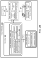
- the path planning system 550 is part of the vehicle controller 300 as shown in FIG. 2A ; while in other examples, the path planning system 550 is part of the DNN 500 as shown in FIG. 2B .
- the DNN 500a sends the controller 300 data output 508 including the selected trailer 200a and the location of the selected trailer 200a with respect to the tow vehicle 100.
- the path planning system 550a plans the path 552 between the tow vehicle 100 and the selected trailer 200a.
- the path planning system 550a may use several methods to determine the path 552.
- FIGS. 3A and 3B provide a method for path planning.
- the path planning system 550a extends its fore-aft axis Y in the rearward direction R while the trailer 200a extends a fore-aft axis about the length of the trailer 200 in a forward direction.
- the path planning system 550a draws a first circle 554 tangent at a first tangent point 555 to the tow vehicle fore-aft axis Y facing the trailer fore-aft axis, and a second circle 556 tangent at a second tangent point 557 to the trailer fore-aft axis facing the tow vehicle fore-aft axis Y.
- the first and second circles 554, 556 intersect at an intersection point 558.
- the size of the first and second circles 554, 556 may be adjusted and manipulated based on the distance between the tow vehicle 100 and the trailer 200, obstacles and object positioned between the tow vehicle 100 and the trailer 200, and any other considerations.
- the path planning system 550a determines the path 552 by following the tow vehicle fore-aft axis Y until the first tangent point 555, then moving along an arc of the first circle 554 until the intersection point 558, then moving along an arc of the second circle 556 until the second tangent point 557, then following the trailer fore-aft axis.
- the planned path 552 positions the tow vehicle 100 in an orientation aligned generally parallel with the trailer 200 and facing away from the trailer 200a, where the hitch 160 of the tow vehicle 100 is substantially aligned with the hitch 210 of the trailer 200.
- FIG. 3A shows an example of the path 552 where the fore-aft axis Y of the tow vehicle 100 is substantially parallel to the fore-aft axis T of the trailer 200a.
- FIG. 3B shows an example of the path 552 where the fore-aft axis Y of the tow vehicle 100 is not substantially parallel to the fore-aft axis T of the trailer 200a.
- the planned path 552 of FIG. 3B is determined similar to the planned path 552 of FIG. 3A .
- the DNN 500 continuously sends the vehicle controller 300 the location of the selected trailer 200a with respect to the tow vehicle 100 as the tow vehicle 100 moves along the planned path 552, based on the received sensor system data 402, i.e., images 412. Since the images 412 are updated as the tow vehicle 100 approaches the selected trailer 200a, then the location of the selected trailer 200a with respect to the tow vehicle 100 also changes as the tow vehicle 100 moves closer to the selected trailer 200a.
- the DNN 500 identifies one or more objects along the planned path 552 and sends the path planning system 550a data relating to the position of the one or more objects.
- the path planning system 550a may recalculate the planned path 552 to avoid the one or more objects.
- the path planning system 550a determines a probability of collision and if the probability of collision exceeds a predetermined threshold, the path planning system 550a adjusts the planned path 552 and sends an adjusted planned path 552 to the path following sub-system 320.
- the DNN 500 includes the path planning system 550b.
- the path planning system 550b may determine a path 552 based on learned behaviors. For example, the DNN 500 determines the position of the selected trailer 200a, and based on the position determines a path 552 for the tow vehicle 100. In some examples, the determined path 552 may be similar to the path described with respect to FIGS. 3A and 3B . However, other path determination methods may also be possible.
- the DNN 500 i.e., the path planning system 550b of the DNN 500 adjusts the planned path 552 based on one or more objects (moving or stationary) that may be identified along the planned path 552 as the tow vehicle 100 is moving about the path 552.
- the path planning system 550b determines a probability of collision and if the probability of collision exceeds a predetermined threshold, the path planning system 550b adjust the path and sends an adjusted path 552 to the path following sub-system 320.
- the path following sub-system 320 includes one or more behaviors 322-330 that once executed allow for the autonomous driving of the tow vehicle 100 along the planned path 552.
- the behaviors 322-330 may include, but are not limited to a braking behavior 322, a speed behavior 324, a steering behavior 326, a hitch connect behavior 328, and a suspension adjustment behavior 330.
- the braking behavior 322 may be executed to either stop the tow vehicle 100 or to slow down the tow vehicle 100 based on the planned path 552.
- the braking behavior 322 sends a signal or command 301 to the drive system 110, e.g., the brake system 120, to either stop the tow vehicle 100 or reduce the speed of the tow vehicle 100.
- the speed behavior 324 may be executed to change the speed of the tow vehicle 100 by either accelerating or decelerating based on the planned path 552.
- the speed behavior 324 sends a signal or command 301 to the brake system 120 for decelerating or the acceleration system 130 for accelerating.
- the steering behavior 326 may be executed to change the direction of the tow vehicle 100 based on the planned path. As such, the steering behavior 326 sends the acceleration system 130 a signal or command 301 indicative of an angle of steering causing the drive system 110 to change direction.
- FIGS. 4A-4C show the tow vehicle 100 at an initial position Pi ( FIG. 4A ), an intermediate position P M ( FIG. 4B ), and a final position P F ( FIG. 4C ) or a connected position, with respect to the selected trailer 200a.
- the tow vehicle 100 is at the initial position Pr relative to the trailer 200 prior to initiating autonomous maneuvering towards the selected trailer 200a.
- an initial distance D I between the tow vehicle 100 and the selected trailer 200a is about 15 meters.
- the tow vehicle 100 autonomously maneuvers along the planned path 552 until the tow vehicle 100 reaches an intermediate position P M being an intermediate distance D M from the selected trailer 200a, as shown in FIG. 4B .
- the tow vehicle hitch 160 is in an orientation aligned generally parallel with the selected trailer 200a and the tow vehicle hitch 160 is substantially aligned with the trailer hitch 210 of the trailer 200a.
- the vehicle fore-aft Y defines a plane that extends along the vehicle vertical axis Z and which in turn is aligned with the trailer fore-aft T extending along a trailer vertical axis.
- the intermediate distance D M is about 1 meter from the selected trailer 200a.
- the hitch connect behavior 328 executes to connect the vehicle hitch 160 with the trailer hitch 210.
- the DNN 500 determines a relative height H R between a top portion of the tow vehicle hitch ball 162 and a bottom portion of the trailer hitch coupler 212.
- the trailer hitch coupler 212 releasably receives the tow vehicle hitch ball 162.
- the relative height H R has to equal zero or less than zero allowing the tow vehicle hitch ball 162 to move under and be inserted in the trailer hitch coupler 212. Therefore, when the hitch connect behavior 328 receives, from the DNN 500, a relative height H R between the tow vehicle hitch ball 162 and the trailer hitch coupler 212 being greater than zero, then the hitch connect behavior 328 sends a command to the suspension adjustment behavior 330 to execute and issue a command 301 to the suspension system 132 to adjust the height of the tow vehicle 100 reducing the relative height H R based on the measurements from the DNN 500.
- the hitch connect behavior 328 When the hitch connect behavior 328 receives a relative height H R that is equal to or less than zero, then the hitch connect behavior 328 issues a command 301 to the drive system 110 to maneuver along the remainder of the path 552, i.e., from the intermediate position P M to the final position P F ( FIG. 4C ), connecting the tow vehicle 100 to the selected trailer 200a. Once the trailer 200 reaches the final position P F , the suspension adjustment behavior 330 issues a command 301 to the suspension system 132 to adjust the height of the tow vehicle 100 resulting in the trailer hitch coupler 212 receiving the tow vehicle hitch ball 162 as shown in FIG. 5D .
- FIG. 6 illustrates an example arrangement of operations for a method 600 of autonomously maneuvering a tow vehicle 100 (as shown in FIGS. 1-5D ) towards a selected trailer 200, 200a.
- the method 600 includes receiving an indication that a driver wants to autonomously hitch the tow vehicle 100 to a trailer 200, 200a-c.
- the indication may be by way of a selection on the user interface 140 of the tow vehicle 100, putting the tow vehicle in reverse (without reversing), or any other indication.
- the DNN 500 detects and locates one or more trailers 200, 200a-c behind the tow vehicle 100 and displays on the user interface 140 trailer representations 146, 146a-c associated with the one or more identified trailers 200, 200a-c respectively.
- the method 600 waits for a driver selection 144 from the one or more trailer representations 146, 146a-c.
- the driver selects a trailer representation 146, 146a-c associated with a selected trailer 200a
- the method 600 includes planning a path 552 from an initial position P I of the tow vehicle 100 to a final position P F with respect to the selected trailer 200a.
- the path planning system 550, 550a, 550b plans the path 552.
- the path planning system 550, 550a, 550b may be part of the controller 300 ( FIG. 2A ) or part of the DNN 500 ( FIG. 2B ).
- the method 600 includes executing the path following sub-system 320.
- the method 600 determines if the tow vehicle 100 is within a predetermined distance from the selected trailer 200a, i.e., the method 600 determines if the tow vehicle 100 has reached the intermediate position P M .
- the method 600 at decision block 612 includes determining a relative height H R between a top portion of the hitch ball 162 of the tow vehicle 100 and a bottom portion of the hitch coupler 212 of the selected trailer 200a and determines if the hitch coupler 212 can releasably receive the hitch ball 162 based on the relative height H R .
- the method 600 includes determining if the relative height H R equals to zero. If the relative height H R is not equal to zero, then at block 616, the method 600 includes adjusting the suspension of the tow vehicle 100 and then determining the relative height H R and checking if the relative height H R equals to or less than zero at block 614.
- the method 600 at block 618 includes continuing maneuvering about the path 552 from the intermediate position P M to the final position P F connecting the hitch ball 162 of the tow vehicle 100 with the hitch coupler 212 of the selected trailer 200a.
- the method 600 includes adjusting the height of the tow vehicle 100 resulting in the trailer hitch coupler 212 receiving the tow vehicle hitch ball 162 as shown in FIG. 5D .
- FIG. 7 is a schematic view of an exemplary arrangement of operations for a method 700 of maneuvering a tow vehicle 100 in reverse for attachment to a trailer 200, 200a-c according to the description of FIGS. 1-5D .
- the method 700 includes receiving, at a computing device (e.g., a controller 300 and a deep neural network 500 in communication with the controller 300), one or more images 412 from one or more cameras 410, 410a-d positioned on a back portion of the vehicle 100.
- the image(s) 412 capture a rearward view of the vehicle 100. Therefore, the image(s) 412 may include one or more trailer 200, 200a-c positioned behind the vehicle 100.
- the method 700 includes identifying, by the computing device, one or more trailers 200, 200a-c within the one or more images 412.
- the method 700 includes receiving, at the computing device, an indication of a selected trailer 200, 200a-c from the one or more trailers 200, 200a-c.
- the computing device is in communication with a user interface 140 (e.g., a display) configured to receive the driver selection 144 of the selected trailer 200, 200a-c.
- the user interface 140 is positioned in the vehicle 100; however, the user interface 140 may be, but not limited to, a handheld table, a smart phone, or a computer, positioned inside or outside the vehicle.
- the method 700 includes determining, at the computing device (e.g., path planning system 550, 550a, 550b), a vehicle path 552 from an initial position Pi to a final position P F .
- the vehicle path 552 includes maneuvers configured to move the vehicle 100 in a rearward direction R along the vehicle path 552 from the initial position P I to the final position P F .
- the method 700 includes executing, by the computing device, one or more behaviors 322-330 causing the vehicle 100 to take an action to autonomously follow the vehicle path 552 and execute the maneuvers.
- the one or more behaviors 322-330 include a braking behavior 322, a speed behavior 324, a steering behavior 326, a hitch connect behavior 328, and a suspension adjustment behavior 330.
- the method 700 includes receiving, at the computing device, one or more sensor system data 402 from a sensor system 400 in communication with the computing device.
- the sensor system data 402 may include images 412 from one or more cameras 410a, 410a-d, and/or sensor data from one or more sensors 420.
- the method 700 may include detecting, by the computing device, one or more objects along or adjacent to the vehicle path 552 from the sensor system data 402.
- the method 700 includes adjusting, by the computing device (e.g., path planning system 550, 550a, 550b), the vehicle path 552 based on the one or more objects detected from the sensor system data 402.
- the vehicle path 552 may include the initial position Pi, an intermediate position P M , and the final position P F .
- the intermediate position P M has a distance D M to the final position P F being less than a distance between the intermediate position and the initial position P I .
- the distance D I between the initial position Pr and the final position P F is greater than the distance D M between the intermediate position P M and the final position P F .
- the trailer 200, 200a-c is in an orientation aligned generally parallel with the trailer 200, 200a-c and facing away from the trailer 200, 200a-c.
- the method 700 includes at the final position P F , determining, by the computing device an adjustment height.
- the adjustment height being a height that the vehicle 100 has to be raised for a hitch coupler 212 of the trailer 200, 200a-c to receive a tow vehicle 100 hitch ball 162.
- the method 700 also includes sending, from the computing device to a suspension system 132 of the vehicle 100, a command 301 to adjust a vehicle suspension based on the adjustment height.
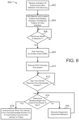
- FIG. 8 is a schematic view of another exemplary arrangement of operations for a method 800 of maneuvering a tow vehicle 100 in reverse for attachment to a trailer 200, 200a-c according to the description of FIGS. 1-5D .
- the method 800 includes detecting, at a neural network 500 of the vehicle 100, one or more trailers 200, 200a-c within one or more images 412.
- the one or more neural network 500 receives the images 412 from one or more cameras 410 positioned on a rear portion of the vehicle 100 to capture images 412 of a view behind the vehicle 100.
- the method 800 includes receiving, at a user interface 140 in communication with the neural network 500, an indication (e.g., driver selection 144) of a selected trailer 200, 200a-c from the one or more detected trailers 200, 200a-c.
- the method 800 also includes determining, at a computing device (e.g., a controller 300 having a path planning system 550a) in communication with the neural network 500, a vehicle path 552 from an initial position Pi to a final position P F adjacent the trailer 200, 200a-c.
- a computing device e.g., a controller 300 having a path planning system 550a
- the method includes determining, at the neural network 500 (e.g., path planning system 550b) the vehicle path 552 from the initial position P I to the final position P F adjacent the trailer 200, 200a-c.
- both the controller 300 and the deep neural network 500 plan the vehicle path 552.
- the vehicle path 552 includes maneuvers that allow the vehicle 100 to move along the vehicle path 552 from the initial position P I to the final position P F .
- the method 800 includes autonomously following, at a drive system 110 in communication with the computing device, the vehicle path 552 from the initial position P I .
- the drive system 110 includes a brake system 120, an acceleration system 130, and a suspension system 132.
- the method 800 includes stopping or halting, at the drive system 110 (e.g., the brake system 120), the vehicle 100 at an intermediate position P M before reaching the final position P F , the intermediate position P M being closer to the final position P F than the initial position P I .
- the method 800 includes modifying, at the drive system 110 (e.g., suspension system 132), one or more vehicle suspensions associated with the vehicle 100 to align a vehicle hitch 160 with a trailer hitch 210.
- the method 800 includes autonomously following, at the drive system 110, the vehicle path 552 from the intermediate position P M to the final position P F .
- the method 800 includes connecting, at the drive system 110, the vehicle hitch 162 with the trailer hitch 212.
- the maneuvers may include, but are not limited to steering left or right at a specific angle, steering straight, braking, and speeding.
- the method 800 further includes continuously detecting, by the neural network 500, one or more objects within the vehicle path 552 as the vehicle 100 is moving rearwards along the vehicle path 552.
- the method 800 includes altering the vehicle path 552 at the controller 300 (e.g., path planning system 550a) or the neural network 500 (e.g., path planning system 550b).
- connecting the vehicle hitch 162 with the trailer hitch 212 includes modifying one or more vehicle suspensions associated with the vehicle 100 allowing the trailer hitch 212 (e.g., trailer coupler 212) to receive the vehicle hitch 162 (e.g., tow vehicle hitch ball 162).
- Detecting one or more trailers 200, 200a-c may include: capturing, at one or more imaging devices 410, 410a-d in communication with the neural network 500, one or more images 412, where at least one of the one or more imaging devices 410, 410a-d positioned on a back side of the trailer 200, 200a-c facing a rearward direction R.
- the method 800 may also include determining, by the neural network 500, the one or more trailers 200, 200a-c within the at least one image 412.
- implementations of the systems and techniques described here can be realized in digital electronic circuitry, integrated circuitry, specially designed ASICs (application specific integrated circuits), computer hardware, firmware, software, and/or combinations thereof.
- ASICs application specific integrated circuits
- These various implementations can include implementation in one or more computer programs that are executable and/or interpretable on a programmable system including at least one programmable processor, which may be special or general purpose, coupled to receive data and instructions from, and to transmit data and instructions to, a storage system, at least one input device, and at least one output device.
- Implementations of the subject matter and the functional operations described in this specification can be implemented in digital electronic circuitry, or in computer software, firmware, or hardware, including the structures disclosed in this specification and their structural equivalents, or in combinations of one or more of them.
- subject matter described in this specification can be implemented as one or more computer program products, i.e., one or more modules of computer program instructions encoded on a computer readable medium for execution by, or to control the operation of, data processing apparatus.
- the computer readable medium can be a machine-readable storage device, a machine-readable storage substrate, a memory device, a composition of matter effecting a machine-readable propagated signal, or a combination of one or more of them.
- data processing apparatus encompass all apparatus, devices, and machines for processing data, including by way of example a programmable processor, a computer, or multiple processors or computers.
- the apparatus can include, in addition to hardware, code that creates an execution environment for the computer program in question, e.g., code that constitutes processor firmware, a protocol stack, a database management system, an operating system, or a combination of one or more of them.
- a propagated signal is an artificially generated signal, e.g., a machine-generated electrical, optical, or electromagnetic signal that is generated to encode information for transmission to suitable receiver apparatus.
Landscapes
- Engineering & Computer Science (AREA)
- Transportation (AREA)
- Mechanical Engineering (AREA)
- Physics & Mathematics (AREA)
- Automation & Control Theory (AREA)
- Remote Sensing (AREA)
- Aviation & Aerospace Engineering (AREA)
- Radar, Positioning & Navigation (AREA)
- General Physics & Mathematics (AREA)
- Chemical & Material Sciences (AREA)
- Combustion & Propulsion (AREA)
- Electromagnetism (AREA)
- Computer Vision & Pattern Recognition (AREA)
- Multimedia (AREA)
- Human Computer Interaction (AREA)
- Control Of Driving Devices And Active Controlling Of Vehicle (AREA)
- Vehicle Body Suspensions (AREA)
- Traffic Control Systems (AREA)
- Regulating Braking Force (AREA)
- Business, Economics & Management (AREA)
- Health & Medical Sciences (AREA)
- Artificial Intelligence (AREA)
- Evolutionary Computation (AREA)
- Game Theory and Decision Science (AREA)
- Medical Informatics (AREA)
Description
- This disclosure relates to a method of maneuvering a vehicle in reverse for attachment to a trailer and to a vehicle for maneuvering in reverse along a path for attachment to a trailer.
- Trailers are usually unpowered vehicles that are pulled by a powered tow vehicle. A trailer may be a utility trailer, a popup camper, a travel trailer, livestock trailer, flatbed trailer, enclosed car hauler, and boat trailer, among others. The tow vehicle may be a car, a crossover, a truck, a van, a sports-utility-vehicle (SUV), a recreational vehicle (RV), or any other vehicle configured to attach to the trailer and pull the trailer. The trailer may be attached to a powered vehicle using a trailer hitch. A receiver hitch mounts on the tow vehicle and connects to the trailer hitch to form a connection. The trailer hitch may be a ball and socket, a fifth wheel and gooseneck, or a trailer jack. Other attachment mechanisms may also be used. In addition to the mechanical connection between the trailer and the powered vehicle, in some examples, the trailer is electrically connected to the tow vehicle. As such, the electrical connection allows the trailer to take the feed from the powered vehicle's rear light circuit, allowing the trailer to have taillights, turn signals, and brake lights that are in sync with the lights of the powered vehicle.
- Some of the challenges that face tow vehicle drivers are connecting the tow vehicle to the trailer, because more than one person is needed. For example, one person drives the vehicle, e.g., the driver, and another one or more people are needed to view the tow vehicle and the trailer and provide the driver with direction regarding the path the tow vehicle has to take to align with the hitch. If the people providing directions to the driver are not accustomed to hitching a tow vehicle to a trailer, then they may have difficulty providing efficient instructions for directing the path of the tow vehicle.
- Recent advancements in sensor technology have led to improved safety systems for vehicles. Arrangements and methods for detecting and avoiding collisions are becoming available. Such driver assistance systems use sensors located on the vehicle to detect an ongoing collision. In some examples, the system may warn the driver of one or more driving situations to prevent or minimize collisions. Additionally, sensors and cameras may also be used to alert a driver of possible obstacles when the vehicle is traveling in a forward direction. Therefore, it is desirable to provide a system that includes sensors to overcome the challenges faced by drivers of tow vehicles.
- Document
EP 3 081 405 A2 discloses an automated hitch assist system which provides a vehicle operation to move a vehicle into an appropriate location to align a vehicle hitch ball with a hitch of a trailer. Thereby, the hitch assist system may be used particularly along with a suspension adjustment system, an electronic brake system and a steering system. Furthermore, the hitch assist system includes one or more cameras to provide a rear view of the vehicle, wherein the respective images are analyzed by a controller. If multiple trailers are detected, an operator can select the appropriate trailer via a driver input device. The hitch assist system may then calculate a path from an initial position of the vehicle to a final position in which the hitch ball aligns with the trailer hitch, wherein the vehicle will be aligned in a generally axial manner in the final position. Once the path is calculated, the controller sends instructions to the other vehicle systems to move the vehicle. - Document
DE 10 2012 001 380 A1 discloses a driver assistance method for coupling a trailer to a vehicle. If trailer hitches which are located in a detection area of a camera of the vehicle are recognized they will be graphically displayed. A driver can then select an appropriate trailer hitch via a respective steering wheel angle. A path for maneuvering is then calculated and the path will then be carried out automatically. Thereby, several sub-trajectories can be calculated on order to reach the final position in a defined position, particularly a position in which the hitch ball of the vehicle is positioned under the hitch coupler of the trailer, taken into account restrictions or obstacles in the surrounding of the vehicle. DocumentUS 7 777 615 B2 also discloses a driver assistance method for coupling a trailer to a vehicle. - One aspect of the disclosure provides a method of maneuvering a vehicle in reverse for attachment to a trailer. The method includes receiving, at a computing device (e.g., a controller and a deep neural network in communication with the controller), one or more images from one or more cameras positioned on a back portion of the vehicle. The method also includes identifying, by the computing device, one or more trailers within the one or more images. In addition, the method includes receiving, at a computing device, an indication of a selected trailer from the one or more trailers. In some examples, the computing device is in communication with a user interface configured to receive the indication of the selected trailer. The method also includes determining, at the computing device, a vehicle path from an initial position to a final position. The vehicle path includes maneuvers configured to move the vehicle in a rearward direction along the vehicle path from the initial position to the final position, wherein the vehicle path includes the initial position, an intermediate position, and the final position, the intermediate position having a distance to the final position being less than a distance between the intermediate position and the initial position, and wherein at the intermediate position, the vehicle is in an orientation aligned generally parallel with the trailer and facing away from the trailer. The method also includes executing, by the computing device, one or more behaviors causing the vehicle to take an action to autonomously follow the vehicle path and execute the maneuvers. The vehicle path is determined by extending a tow vehicle fore-aft axis in the rearward direction and by extending a trailer fore-aft axis about the length of the trailer in a forward direction, and wherein the vehicle path is determined to be along arcs of a first circle tangent to the extended tow vehicle fore-aft axis facing the trailer fore-aft axis and a second circle tangent to the first circle and the extended trailer fore-aft axis facing the tow vehicle fore-aft axis, wherein the first and second circles intersect at an intersection point.
- Implementations of this aspect of the disclosure may include one or more of the following optional features. In some implementations, the one or more behaviors include a braking behavior, a speed behavior, a steering behavior, a hitch connect behavior, and a suspension adjustment behavior.
- In some examples, the method includes: receiving, at the computing device, one or more sensor data from a sensor system in communication with the computing device; detecting, by the computing device, one or more objects along or adjacent to the vehicle path from the sensor data; and adjusting, by the computing device, the vehicle path based on the one or more objects.
- In some implementations, the method includes at the final position, determining, by the computing device an adjustment height. The adjustment height being a height that the vehicle has to be raised for a hitch coupler of the trailer to receive a tow vehicle hitch ball. The method also includes sending, from the computing device to a suspension system of the vehicle, a command to adjust a vehicle suspension based on the adjustment height.
- Another aspect of the disclosure provides a vehicle for maneuvering in reverse along a path for attachment to a trailer. The vehicle includes one or more cameras positioned on a back portion of the vehicle, and a computing device (e.g., a controller and a deep neural network in communication with the controller) in communication with a user interface. The vehicle also includes non-transitory memory in communication with the computing device. The non-transitory memory stores instruction that when executed on the computing device cause the computing device to perform operations. The operations include: receiving one or more images from the one or more cameras; identifying one or more trailers within the one or more images and receiving an indication of a selected trailer from the one or more trailers. The indication is indicative of a driver selection by way of a user interface. The operations also include determining a vehicle path from an initial position to a final position. The vehicle path includes maneuvers to move the vehicle in a rearward direction along the vehicle path from the initial position to the final position, wherein the vehicle path includes the initial position, an intermediate position, and a final position, the intermediate position having a distance to the final position being less than a distance between the intermediate position and the initial position, and wherein at the intermediate position, the vehicle is in an orientation aligned generally parallel with the trailer and facing away from the trailer. The operations also include executing one or more behaviors causing the vehicle to take an action to autonomously follow the vehicle path and execute the maneuvers. The vehicle path is determined by extending a tow vehicle fore-aft axis in the rearward direction and by extending a trailer fore-aft axis about the length of the trailer in a forward direction, and wherein the vehicle path is determined to be along arcs of a first circle tangent to the extended tow vehicle fore-aft axis facing the trailer fore-aft axis and a second circle tangent to the first circle and the extended trailer fore-aft axis facing the tow vehicle fore-aft axis, wherein the first and second circles intersect at an intersection point.
- Implementations of this aspect of the disclosure may include one or more of the following optional features. In some implementations, the one or more behaviors include a braking behavior, a speed behavior, a steering behavior, a hitch connect behavior, and a suspension adjustment behavior.
- In some implementations, the operations further include receiving one or more sensor data from a sensor system in communication with the computing device, and detecting one or more objects along or adjacent to the vehicle path from the sensor data. The operations may further include adjusting the vehicle path based on the one or more objects.
- The operations may further include at the final position, determining an adjustment height being a height that the vehicle has to be raised for a hitch coupler of the trailer to receive a tow vehicle hitch ball. The operations may also include sending a suspension system of the vehicle, a command to adjust a vehicle suspension based on the adjustment height. In some examples, the computing device includes a controller and a deep neural network in communication with the controller.
- Yet another aspect of the disclosure which does not form part of the presently claimed invention provides a method of maneuvering a vehicle in reverse for attachment to a trailer. The method includes detecting, at a neural network of the vehicle, one or more trailers within one or more images. The method also includes receiving, at a user interface in communication with the neural network, an indication of a selected trailer from the one or more detected trailers. The method also includes determining, at a computing device in communication with the neural network, a vehicle path from an initial position to a final position adjacent the trailer. The vehicle path includes maneuvers configured to move the vehicle along the vehicle path from the initial position to the final position. The method also includes autonomously following, at a drive system in communication with the computing device, the vehicle path from the initial position. The method also includes stopping or halting, at the drive system, the vehicle at an intermediate position before reaching the final position, the intermediate position being closer to the final position than the initial position. The method also includes modifying, at the drive system, one or more vehicle suspensions associated with the vehicle to align a vehicle hitch with a trailer hitch. The method also includes autonomously following, at the drive system, the vehicle path from the intermediate position to the final position. The method also includes connecting, at the drive system, the vehicle hitch with the trailer hitch.
- Implementations of this aspect of the disclosure which does not form part of the presently claimed invention may include one or more of the following optional features. In some implementations, the maneuvers include, steering, braking, and speeding. The method may further include continuously detecting, by the neural network, one or more objects within the vehicle path, as the vehicle is moving along the vehicle path. The method may also include when detecting an object, altering the vehicle path at the computing device. In some examples, connecting the vehicle hitch with the trailer hitch includes modifying one or more vehicle suspensions associated with the vehicle allowing the trailer hitch (e.g., a trailer hitch coupler) to receive the vehicle hitch (e.g., tow vehicle hitch ball 162). Detecting one or more trailers may include capturing, at one or more imaging devices in communication with the neural network, one or more images, at least one of the one or more imaging devices positioned on a back side of the trailer facing a rearward direction. The method may also include determining, by the neural network, the one or more trailers within the at least one image.
- The details of one or more implementations of the disclosure are set forth in the accompanying drawings and the description below. Other aspects, features, and advantages will be apparent from the description and drawings, and from the claims.
-
-
FIG. 1 is a schematic view of an exemplary tow vehicle having a user interface displaying an indication of trailers behind the tow vehicle. -
FIGS. 2A and2B are perspective views of an exemplary tow vehicle. -
FIGS. 3A and3B are perspective views of an exemplary tow vehicle autonomously maneuvering along a planned path. -
FIG. 4A is a perspective view of an exemplary tow vehicle at an initial position. -
FIG. 4B is a perspective view of an exemplary tow vehicle at an intermediate position. -
FIG. 4C is a perspective view of an exemplary tow vehicle at a final position. -
FIGS. 5A-5D are perspective views of an exemplary vehicle hitch connecting to a trailer hitch. -
FIG. 6 is a flow diagram of an exemplary arrangement of operations for maneuvering a tow vehicle in reverse for attachment to a trailer. -
FIGS. 7 and8 are schematic views of exemplary arrangements of operations for maneuvering a tow vehicle in reverse for attachment to a trailer. - Like reference symbols in the various drawings indicate like elements.
- A tow vehicle, such as, but not limited to a car, a crossover, a truck, a van, a sports-utility-vehicle (SUV), and a recreational vehicle (RV) may be configured to tow a trailer. The tow vehicle connects to the trailer by way of a trailer hitch. It is desirable to have a tow vehicle that is capable of autonomously maneuvering towards a trailer and attaching to the trailer, thus eliminating the need for a driver to drive the tow vehicle in a rearward direction while another one or more people provide the driver with directions regarding the path that the tow vehicle has to take to align with the trailer and ultimately a hitch of the trailer. As such, a tow vehicle with an autonomous rearward driving and hitching feature provides a driver with a safer and faster experience when hitching the tow vehicle to the trailer.
- Referring to
FIGS. 1-2B , in some implementations, a driver of atow vehicle 100 wants to tow atrailer 200, 200a-c, for example, a specific trailer 200a-c from a group oftrailers 200, 200a-c. As shown, the group oftrailers 200, 200a-c includes three trailers, however, the group oftrailers 200, 200a-c may include any number of trailers greater than one. Thetow vehicle 100 may be configured to receive an indication of a driver selection 144 associated with a selectedtrailer 200, 200a-c and autonomously drive towards the selectedtrailer 200, 200a-c. Thetow vehicle 100 may include adrive system 110 that maneuvers thetow vehicle 100 across a road surface based on drive commands having x, y, and z components, for example. As shown, thedrive system 110 includes a front right wheel 112, 112a, a front left wheel 112, 112b, a rearright wheel 112, 112c, and a rearleft wheel 112, 112d. Thedrive system 110 may include other wheel configurations as well. Thedrive system 110 may also include abrake system 120 that includes brakes associated with each wheel 112, 112a-d, and anacceleration system 130 that is configured to adjust a speed and direction of thetow vehicle 100. In addition, thedrive system 110 may include a suspension system 132 that includes tires associates with each wheel 112, 112a-d, tire air, springs, shock absorbers, and linkages that connect thetow vehicle 100 to its wheels 112, 112a-d and allows relative motion between thetow vehicle 100 and the wheels 112, 112a-d. The suspension system 132 improves the road handling of thetow vehicle 100 and provides a better ride quality by isolating road noise, bumps, and vibrations. In addition, the suspension system 132 is configured to adjust a height of thetow vehicle 100 allowing a tow vehicle hitch 160 (e.g., a tow vehicle hitch ball 162) to align with a trailer hitch 210 (e.g., trailer hitch coupler 212), which allows for autonomous connection between thetow vehicle 100 and thetrailer 200. - The
tow vehicle 100 may move across the road surface by various combinations of movements relative to three mutually perpendicular axes defined by the tow vehicle 100: a transverse axis X, a fore-aft axis Y, and a central vertical axis Z. The transverse axis x, extends between a right side and a left side of thetow vehicle 100. A forward drive direction along the fore-aft axis Y is designated as F, also referred to as a forward motion. In addition, an aft or rearward drive direction along the fore-aft direction Y is designated as R, also referred to as rearward motion. When the suspension system 132 adjusts the suspension of thetow vehicle 100, thetow vehicle 100 may tilt about the X axis and or Y axis, or move along the central vertical axis Z. - The
tow vehicle 100 may include auser interface 140, such as, a display. Theuser interface 140 receives one or more user commands from the driver via one or more input mechanisms or atouch screen display 142 and/or displays one or more notifications to the driver. Theuser interface 140 is in communication with avehicle controller 300, which is in turn in communication with asensor system 400. In some examples, theuser interface 140 displays an image of an environment of thetow vehicle 100 leading to one or more commands being received by the user interface 140 (from the driver) that initiate execution of one or more behaviors. Thevehicle controller 300 includes a computing device (or processor) 302 (e.g., central processing unit having one or more computing processors) in communication with non-transitory memory 304 (e.g., a hard disk, flash memory, random-access memory) capable of storing instructions executable on the computing processor(s) 302. - The
vehicle controller 300 executes adriver assistance system 310, which in turn includes apath following sub-system 320. Thepath following sub-system 320 receives a planned path 552 (FIGS. 3A and3B ) from a path planning system 550 and executes behaviors 322-330 that send commands 301 to thedrive system 110, causing thetow vehicle 100 to autonomously drive about theplanned path 552 in a rearward direction R. - The
path following sub-system 320 includes, abraking behavior 322, aspeed behavior 324, asteering behavior 326, ahitch connect behavior 328, and asuspension adjustment behavior 330. Each behavior 322-330 causes thetow vehicle 100 to take an action, such as driving backward, turning at a specific angle, breaking, speeding, slowing down, among others. Thevehicle controller 300 may maneuver thetow vehicle 100 in any direction across the road surface by controlling thedrive system 110, more specifically by issuingcommands 301 to thedrive system 110. For example, thevehicle controller 300 may maneuver thetow vehicle 100 from an initial position (as shown inFig. 5A ) to a final position (as shown inFIG. 5C ). In the final position, ahitch ball 162 of thetow vehicle 100 aligns with ahitch coupler 212 of thetrailer 200 connecting thetow vehicle 100 and the selectedtrailer 200, 200a-c. - The
tow vehicle 100 may include asensor system 400 to provide reliable and robust autonomous driving. Thesensor system 400 may include different types of sensors that may be used separately or with one another to create a perception of the environment of thetow vehicle 100 that is used for thetow vehicle 100 to autonomously drive and make intelligent decisions based on objects and obstacles detected by thesensor system 400. The sensors may include, but are not limited to, one or more imaging devices (such as cameras) 410, andsensors 420 such as, but not limited to, radar, sonar, LIDAR (Light Detection and Ranging, which can entail optical remote sensing that measures properties of scattered light to find range and/or other information of a distant target), LADAR (Laser Detection and Ranging), etc. In addition, the camera(s) 410 and the sensor(s) 420 may be used to alert the driver of possible obstacles when thetow vehicle 100 is traveling in the forward direction F or in the rearward direction R, by way of audible alerts and/or visual alerts via theuser interface 140. Therefore, thesensor system 400 is especially useful for increasing safety intow vehicles 100 which operate under semi-autonomous or autonomous conditions. - In some implementations, the
tow vehicle 100 includes arear camera 410, 410a that is mounted to provide a view of a rear driving path for thetow vehicle 100. Additionally, in some examples, thetow vehicle 100 includes afront camera tow vehicle 100, aright camera 410, 410c positioned on the right side of thetow vehicle 100, and aleft camera 410, 410d positioned on the left side of thetow vehicle 100. The left andright cameras 410, 410c, 410d provide additional side views of thetow vehicle 100. In this case, thetow vehicle 100 may detect object and obstacles positioned on either side of thetow vehicle 100, in addition to the objects and obstacle detected along the front and rear driving paths. The camera(s) 410, 410a-d may be a monocular camera, binocular camera, or another type of sensing device capable of providing a view of the rear travelling path of thetow vehicle 100. - In some implementations, the
tow vehicle 100 includes one or more Neural Networks (NN) 500, for example, Deep Neural Networks (DNN) to improve the autonomous driving of thetow vehicle 100.DNNs 500 are computational approaches used in computer science, among other disciplines, and are based on a large collection of neural unites, loosely imitating the way a biological brain solves problems with large clusters of biological neurons connected by axons.DNNs 500 are self-learning and trained, rather than programed, and excel in areas where the solution feature detection is difficult to express in a traditional computer program. In other words,DNNs 500 are a set of algorithms that are designed to recognize patterns.DNNs 500 interpret sensor system data 402 (e.g., from the sensor system 400) through a machine perception, labeling or clustering raw input. The recognized patters are numerical, vectors, into which all-real-world data, such as images, text, sound, or time series is translates. TheDNN 500 includes multiple layers of nonlinear processing units 502 in communication with DNNnon-transitory memory 504. The DNNnon-transitory memory 504 stores instructions that when executed on the nonlinear processing units 502 cause theDNN 500 to provide anoutput outputs DNN 500 is capable of determining the position of thetrailer hitch 210 associated with a selectedtrailer 200, 200a-c based onimages 412 orsensor data 422 of therearward path 552 between thetow vehicle 100 and thetrailer 200 based on the location of the selectedtrailer 200, thus eliminating the need of using a DGPS or a GPS. - The
DNN 500 receives sensor system data 402 (includingimages 412 and/or sensor data 422) and based on the receiveddata 402 provides animage output 506 to theuser interface 140 and/or adata output 508 to thevehicle controller 300. In some examples, theDNN 500 receives image(s) 412 of a rear view of thetow vehicle 100 from thecamera 410 in communication with theDNN 500. TheDNN 500 analyzes theimage 412 and identifies one ormore trailers 200 in the receivedimage 412. TheDNN 500 may also receivesensor data 422 from thesensors 420 in communication with theDNN 500, and analyze the receivedsensor data 422. Based on the analyzed images 412 (or the analyzedimages 412 and the sensor data 422), theDNN 500 identifies the location of each identifiedtrailer 200 relative to thetow vehicle 100, for example by way of a coordinate system. As such, theDNN 500 displays on theuser interface 140 the receivedimages 412 displayingrepresentations trailers 200, 200a-c located at a distance behind thetow vehicle 100. As shown inFIG. 1 , first, second, and third trailers 200a, 200b, 200c are positioned behind thetow vehicle 100. As such, theuser interface 140 displays first, second, andthird trailer representations - The driver may select one of the
trailer representations tow vehicle 100 to autonomously drive and connect to thetrailer 200, 200a-c associated with the selectedtrailer representation 146, i.e., the driver selection 144. In some examples, the user interface is atouch screen display 142; as such, the driver may point his finger and select thetrailer representation 146. In other examples, theuser interface 140 is not a touchscreen and the driver may use an input device, such as, but not limited to, a rotary knob or a mouse to select one of thetrailer representations - When the driver selects which
trailer 200, 200a-c he/she wants thetow vehicle 100 to connect to, a path planning system 550 plans a path 552 (FIGS. 3A and3B ) between thetow vehicle 100 and thetrailer 200 based on the location of the selectedtrailer 200, 200a-c (determined by theDNN 500 from the received sensor system data 402) relative to a position of the tow vehicle 100 (e.g., orientation and distance). As thetow vehicle 100 is autonomously backing up towards the selected trailer 200 (the first trailer 200a as shown inFIG. 1 ). Theplanned path 552 allows thetow vehicle 100 to autonomously drive and connect to thetrailer 200. The path planning system 550 plans thepath 552 for thetow vehicle 100 to autonomously maneuver such that thetow vehicle 100, in an intermediate position within a predetermined distance D from thetrailer 200, is in an orientation aligned generally parallel with thetrailer 200 and facing away from thetrailer 200, where thehitch 160 of thetow vehicle 100 is substantially aligned with thehitch 210 of thetrailer 200. - In some examples, the path planning system 550 is part of the
vehicle controller 300 as shown inFIG. 2A ; while in other examples, the path planning system 550 is part of theDNN 500 as shown inFIG. 2B . Referring toFIG. 2A , when the driver selects thetrailer representation 146a associated with the trailer 200a (e.g., the first trailer 200a) that the driver wants thetow vehicle 100 to autonomously drive towards and connect with, the DNN 500a sends thecontroller 300data output 508 including the selected trailer 200a and the location of the selected trailer 200a with respect to thetow vehicle 100. In this case, the path planning system 550a plans thepath 552 between thetow vehicle 100 and the selected trailer 200a. The path planning system 550a may use several methods to determine thepath 552.FIGS. 3A and3B provide a method for path planning. In some examples, the path planning system 550a extends its fore-aft axis Y in the rearward direction R while the trailer 200a extends a fore-aft axis about the length of thetrailer 200 in a forward direction. The path planning system 550a draws afirst circle 554 tangent at a firsttangent point 555 to the tow vehicle fore-aft axis Y facing the trailer fore-aft axis, and asecond circle 556 tangent at a secondtangent point 557 to the trailer fore-aft axis facing the tow vehicle fore-aft axis Y. The first andsecond circles intersection point 558. The size of the first andsecond circles tow vehicle 100 and thetrailer 200, obstacles and object positioned between thetow vehicle 100 and thetrailer 200, and any other considerations. The path planning system 550a determines thepath 552 by following the tow vehicle fore-aft axis Y until the firsttangent point 555, then moving along an arc of thefirst circle 554 until theintersection point 558, then moving along an arc of thesecond circle 556 until the secondtangent point 557, then following the trailer fore-aft axis. As such, theplanned path 552 positions thetow vehicle 100 in an orientation aligned generally parallel with thetrailer 200 and facing away from the trailer 200a, where thehitch 160 of thetow vehicle 100 is substantially aligned with thehitch 210 of thetrailer 200. In other words, where the fore-aft axis Y of thetow vehicle 100 is substantially aligned with the fore-aft axis T of the trailer 200a.FIG. 3A shows an example of thepath 552 where the fore-aft axis Y of thetow vehicle 100 is substantially parallel to the fore-aft axis T of the trailer 200a. WhileFIG. 3B shows an example of thepath 552 where the fore-aft axis Y of thetow vehicle 100 is not substantially parallel to the fore-aft axis T of the trailer 200a. However, theplanned path 552 ofFIG. 3B is determined similar to theplanned path 552 ofFIG. 3A . - With continued reference to
FIGS. 2A ,3A and3B , in some examples, when thetow vehicle 100 is autonomously driving along theplanned path 552, theDNN 500 continuously sends thevehicle controller 300 the location of the selected trailer 200a with respect to thetow vehicle 100 as thetow vehicle 100 moves along theplanned path 552, based on the receivedsensor system data 402, i.e.,images 412. Since theimages 412 are updated as thetow vehicle 100 approaches the selected trailer 200a, then the location of the selected trailer 200a with respect to thetow vehicle 100 also changes as thetow vehicle 100 moves closer to the selected trailer 200a. In some examples, theDNN 500 identifies one or more objects along theplanned path 552 and sends the path planning system 550a data relating to the position of the one or more objects. In this case, the path planning system 550a may recalculate theplanned path 552 to avoid the one or more objects. In some examples, the path planning system 550a determines a probability of collision and if the probability of collision exceeds a predetermined threshold, the path planning system 550a adjusts theplanned path 552 and sends an adjustedplanned path 552 to thepath following sub-system 320. - Referring back to
FIG. 2B , in some implementations theDNN 500 includes the path planning system 550b. As such, the path planning system 550b may determine apath 552 based on learned behaviors. For example, theDNN 500 determines the position of the selected trailer 200a, and based on the position determines apath 552 for thetow vehicle 100. In some examples, thedetermined path 552 may be similar to the path described with respect toFIGS. 3A and3B . However, other path determination methods may also be possible. Similarly, theDNN 500, i.e., the path planning system 550b of theDNN 500 adjusts theplanned path 552 based on one or more objects (moving or stationary) that may be identified along theplanned path 552 as thetow vehicle 100 is moving about thepath 552. In some examples, the path planning system 550b determines a probability of collision and if the probability of collision exceeds a predetermined threshold, the path planning system 550b adjust the path and sends anadjusted path 552 to thepath following sub-system 320. - Referring back to
FIGS. 2A and2B , once the path planning system 550 plans apath 552, thepath following sub-system 320 is configured to execute behaviors that cause thedrive system 110 to autonomously follow theplanned path 552. Therefore, thepath following sub-system 320 includes one or more behaviors 322-330 that once executed allow for the autonomous driving of thetow vehicle 100 along theplanned path 552. The behaviors 322-330 may include, but are not limited to abraking behavior 322, aspeed behavior 324, asteering behavior 326, ahitch connect behavior 328, and asuspension adjustment behavior 330. - The
braking behavior 322 may be executed to either stop thetow vehicle 100 or to slow down thetow vehicle 100 based on theplanned path 552. Thebraking behavior 322 sends a signal orcommand 301 to thedrive system 110, e.g., thebrake system 120, to either stop thetow vehicle 100 or reduce the speed of thetow vehicle 100. - The
speed behavior 324 may be executed to change the speed of thetow vehicle 100 by either accelerating or decelerating based on theplanned path 552. Thespeed behavior 324 sends a signal orcommand 301 to thebrake system 120 for decelerating or theacceleration system 130 for accelerating. - The
steering behavior 326 may be executed to change the direction of thetow vehicle 100 based on the planned path. As such, thesteering behavior 326 sends the acceleration system 130 a signal or command 301 indicative of an angle of steering causing thedrive system 110 to change direction. -
FIGS. 4A-4C show thetow vehicle 100 at an initial position Pi (FIG. 4A ), an intermediate position PM (FIG. 4B ), and a final position PF (FIG. 4C ) or a connected position, with respect to the selected trailer 200a. Referring toFIG. 4A , thetow vehicle 100 is at the initial position Pr relative to thetrailer 200 prior to initiating autonomous maneuvering towards the selected trailer 200a. In some examples, an initial distance DI between thetow vehicle 100 and the selected trailer 200a is about 15 meters. Thetow vehicle 100 autonomously maneuvers along theplanned path 552 until thetow vehicle 100 reaches an intermediate position PM being an intermediate distance DM from the selected trailer 200a, as shown inFIG. 4B . In the intermediate position PM, thetow vehicle hitch 160 is in an orientation aligned generally parallel with the selected trailer 200a and thetow vehicle hitch 160 is substantially aligned with thetrailer hitch 210 of the trailer 200a. In other words, the vehicle fore-aft Y defines a plane that extends along the vehicle vertical axis Z and which in turn is aligned with the trailer fore-aft T extending along a trailer vertical axis. In some examples, the intermediate distance DM is about 1 meter from the selected trailer 200a. - Referring to
FIGS. 5A-5D , in some examples, when thetow vehicle 100 is in the intermediate position PM the hitch connectbehavior 328 executes to connect thevehicle hitch 160 with thetrailer hitch 210. TheDNN 500 determines a relative height HR between a top portion of the towvehicle hitch ball 162 and a bottom portion of thetrailer hitch coupler 212. To connect thetow vehicle 100 and the selected trailer 200a, thetrailer hitch coupler 212 releasably receives the towvehicle hitch ball 162. Therefore, to connect the towvehicle hitch ball 162 to thetrailer hitch coupler 212, the relative height HR has to equal zero or less than zero allowing the towvehicle hitch ball 162 to move under and be inserted in thetrailer hitch coupler 212. Therefore, when the hitch connectbehavior 328 receives, from theDNN 500, a relative height HR between the towvehicle hitch ball 162 and thetrailer hitch coupler 212 being greater than zero, then the hitch connectbehavior 328 sends a command to thesuspension adjustment behavior 330 to execute and issue acommand 301 to the suspension system 132 to adjust the height of thetow vehicle 100 reducing the relative height HR based on the measurements from theDNN 500. When the hitch connectbehavior 328 receives a relative height HR that is equal to or less than zero, then the hitch connectbehavior 328 issues acommand 301 to thedrive system 110 to maneuver along the remainder of thepath 552, i.e., from the intermediate position PM to the final position PF (FIG. 4C ), connecting thetow vehicle 100 to the selected trailer 200a. Once thetrailer 200 reaches the final position PF, thesuspension adjustment behavior 330 issues acommand 301 to the suspension system 132 to adjust the height of thetow vehicle 100 resulting in thetrailer hitch coupler 212 receiving the towvehicle hitch ball 162 as shown inFIG. 5D . -
FIG. 6 illustrates an example arrangement of operations for amethod 600 of autonomously maneuvering a tow vehicle 100 (as shown inFIGS. 1-5D ) towards a selectedtrailer 200, 200a. Atblock 602, themethod 600 includes receiving an indication that a driver wants to autonomously hitch thetow vehicle 100 to atrailer 200, 200a-c. The indication may be by way of a selection on theuser interface 140 of thetow vehicle 100, putting the tow vehicle in reverse (without reversing), or any other indication. Atblock 604, theDNN 500 detects and locates one ormore trailers 200, 200a-c behind thetow vehicle 100 and displays on theuser interface 140trailer representations trailers 200, 200a-c respectively. Atdecision block 606, themethod 600 waits for a driver selection 144 from the one ormore trailer representations trailer representation block 608, themethod 600 includes planning apath 552 from an initial position PI of thetow vehicle 100 to a final position PF with respect to the selected trailer 200a. In some examples, the path planning system 550, 550a, 550b plans thepath 552. The path planning system 550, 550a, 550b may be part of the controller 300 (FIG. 2A ) or part of the DNN 500 (FIG. 2B ). Atblock 610, themethod 600 includes executing thepath following sub-system 320. Atdecision block 612, themethod 600 determines if thetow vehicle 100 is within a predetermined distance from the selected trailer 200a, i.e., themethod 600 determines if thetow vehicle 100 has reached the intermediate position PM. When thetow vehicle 100 reaches the intermediate position PM, themethod 600 atdecision block 612 includes determining a relative height HR between a top portion of thehitch ball 162 of thetow vehicle 100 and a bottom portion of thehitch coupler 212 of the selected trailer 200a and determines if thehitch coupler 212 can releasably receive thehitch ball 162 based on the relative height HR. In other words, themethod 600 includes determining if the relative height HR equals to zero. If the relative height HR is not equal to zero, then atblock 616, themethod 600 includes adjusting the suspension of thetow vehicle 100 and then determining the relative height HR and checking if the relative height HR equals to or less than zero atblock 614. Once the relative height HR is equal to or is less than zero, then themethod 600 atblock 618 includes continuing maneuvering about thepath 552 from the intermediate position PM to the final position PF connecting thehitch ball 162 of thetow vehicle 100 with thehitch coupler 212 of the selected trailer 200a. Once thetrailer 200 reaches the final position PF, themethod 600 includes adjusting the height of thetow vehicle 100 resulting in thetrailer hitch coupler 212 receiving the towvehicle hitch ball 162 as shown inFIG. 5D . -
FIG. 7 is a schematic view of an exemplary arrangement of operations for amethod 700 of maneuvering atow vehicle 100 in reverse for attachment to atrailer 200, 200a-c according to the description ofFIGS. 1-5D . Atblock 702, themethod 700 includes receiving, at a computing device (e.g., acontroller 300 and a deepneural network 500 in communication with the controller 300), one ormore images 412 from one ormore cameras 410, 410a-d positioned on a back portion of thevehicle 100. The image(s) 412 capture a rearward view of thevehicle 100. Therefore, the image(s) 412 may include one ormore trailer 200, 200a-c positioned behind thevehicle 100. Atblock 704, themethod 700 includes identifying, by the computing device, one ormore trailers 200, 200a-c within the one ormore images 412. Atblock 706, themethod 700 includes receiving, at the computing device, an indication of a selectedtrailer 200, 200a-c from the one ormore trailers 200, 200a-c. In some examples, the computing device is in communication with a user interface 140 (e.g., a display) configured to receive the driver selection 144 of the selectedtrailer 200, 200a-c. In some examples, theuser interface 140 is positioned in thevehicle 100; however, theuser interface 140 may be, but not limited to, a handheld table, a smart phone, or a computer, positioned inside or outside the vehicle. At block 708, themethod 700 includes determining, at the computing device (e.g., path planning system 550, 550a, 550b), avehicle path 552 from an initial position Pi to a final position PF. Thevehicle path 552 includes maneuvers configured to move thevehicle 100 in a rearward direction R along thevehicle path 552 from the initial position PI to the final position PF. Atblock 710, themethod 700 includes executing, by the computing device, one or more behaviors 322-330 causing thevehicle 100 to take an action to autonomously follow thevehicle path 552 and execute the maneuvers. - In some implementations, the one or more behaviors 322-330 include a
braking behavior 322, aspeed behavior 324, asteering behavior 326, ahitch connect behavior 328, and asuspension adjustment behavior 330. - In some examples, the
method 700 includes receiving, at the computing device, one or moresensor system data 402 from asensor system 400 in communication with the computing device. Thesensor system data 402 may includeimages 412 from one or more cameras 410a, 410a-d, and/or sensor data from one ormore sensors 420. Themethod 700 may include detecting, by the computing device, one or more objects along or adjacent to thevehicle path 552 from thesensor system data 402. Themethod 700 includes adjusting, by the computing device (e.g., path planning system 550, 550a, 550b), thevehicle path 552 based on the one or more objects detected from thesensor system data 402. Thevehicle path 552 may include the initial position Pi, an intermediate position PM, and the final position PF. The intermediate position PM has a distance DM to the final position PF being less than a distance between the intermediate position and the initial position PI. In other words, the distance DI between the initial position Pr and the final position PF is greater than the distance DM between the intermediate position PM and the final position PF. In some examples, at the intermediate position PM, thetrailer 200, 200a-c is in an orientation aligned generally parallel with thetrailer 200, 200a-c and facing away from thetrailer 200, 200a-c. - In some implementations, the
method 700 includes at the final position PF, determining, by the computing device an adjustment height. The adjustment height being a height that thevehicle 100 has to be raised for ahitch coupler 212 of thetrailer 200, 200a-c to receive atow vehicle 100hitch ball 162. Themethod 700 also includes sending, from the computing device to a suspension system 132 of thevehicle 100, acommand 301 to adjust a vehicle suspension based on the adjustment height. -
FIG. 8 is a schematic view of another exemplary arrangement of operations for amethod 800 of maneuvering atow vehicle 100 in reverse for attachment to atrailer 200, 200a-c according to the description ofFIGS. 1-5D . Atblock 802, themethod 800 includes detecting, at aneural network 500 of thevehicle 100, one ormore trailers 200, 200a-c within one ormore images 412. The one or moreneural network 500 receives theimages 412 from one ormore cameras 410 positioned on a rear portion of thevehicle 100 to captureimages 412 of a view behind thevehicle 100. At block 804, themethod 800 includes receiving, at auser interface 140 in communication with theneural network 500, an indication (e.g., driver selection 144) of a selectedtrailer 200, 200a-c from the one or more detectedtrailers 200, 200a-c. Atblock 806, themethod 800 also includes determining, at a computing device (e.g., acontroller 300 having a path planning system 550a) in communication with theneural network 500, avehicle path 552 from an initial position Pi to a final position PF adjacent thetrailer 200, 200a-c. Alternatively, in some examples, the method includes determining, at the neural network 500 (e.g., path planning system 550b) thevehicle path 552 from the initial position PI to the final position PF adjacent thetrailer 200, 200a-c. In yet another example, both thecontroller 300 and the deepneural network 500 plan thevehicle path 552. Thevehicle path 552 includes maneuvers that allow thevehicle 100 to move along thevehicle path 552 from the initial position PI to the final position PF. Atblock 808, themethod 800 includes autonomously following, at adrive system 110 in communication with the computing device, thevehicle path 552 from the initial position PI. Thedrive system 110 includes abrake system 120, anacceleration system 130, and a suspension system 132. Atblock 810, themethod 800 includes stopping or halting, at the drive system 110 (e.g., the brake system 120), thevehicle 100 at an intermediate position PM before reaching the final position PF, the intermediate position PM being closer to the final position PF than the initial position PI. Atblock 812, themethod 800 includes modifying, at the drive system 110 (e.g., suspension system 132), one or more vehicle suspensions associated with thevehicle 100 to align avehicle hitch 160 with atrailer hitch 210. Atblock 814, themethod 800 includes autonomously following, at thedrive system 110, thevehicle path 552 from the intermediate position PM to the final position PF. Atblock 816, themethod 800 includes connecting, at thedrive system 110, thevehicle hitch 162 with thetrailer hitch 212. - In some implementations, the maneuvers may include, but are not limited to steering left or right at a specific angle, steering straight, braking, and speeding. In some examples, the
method 800 further includes continuously detecting, by theneural network 500, one or more objects within thevehicle path 552 as thevehicle 100 is moving rearwards along thevehicle path 552. When theneural network 500 detects an object, themethod 800 includes altering thevehicle path 552 at the controller 300 (e.g., path planning system 550a) or the neural network 500 (e.g., path planning system 550b). In some examples, connecting thevehicle hitch 162 with thetrailer hitch 212 includes modifying one or more vehicle suspensions associated with thevehicle 100 allowing the trailer hitch 212 (e.g., trailer coupler 212) to receive the vehicle hitch 162 (e.g., tow vehicle hitch ball 162). Detecting one ormore trailers 200, 200a-c may include: capturing, at one ormore imaging devices 410, 410a-d in communication with theneural network 500, one ormore images 412, where at least one of the one ormore imaging devices 410, 410a-d positioned on a back side of thetrailer 200, 200a-c facing a rearward direction R. Themethod 800 may also include determining, by theneural network 500, the one ormore trailers 200, 200a-c within the at least oneimage 412. - Various implementations of the systems and techniques described here can be realized in digital electronic circuitry, integrated circuitry, specially designed ASICs (application specific integrated circuits), computer hardware, firmware, software, and/or combinations thereof. These various implementations can include implementation in one or more computer programs that are executable and/or interpretable on a programmable system including at least one programmable processor, which may be special or general purpose, coupled to receive data and instructions from, and to transmit data and instructions to, a storage system, at least one input device, and at least one output device.
- These computer programs (also known as programs, software, software applications or code) include machine instructions for a programmable processor, and can be implemented in a high-level procedural and/or object-oriented programming language, and/or in assembly/machine language. As used herein, the terms "machine-readable medium" and "computer-readable medium" refer to any computer program product, apparatus and/or device (e.g., magnetic discs, optical disks, memory, Programmable Logic Devices (PLDs)) used to provide machine instructions and/or data to a programmable processor, including a machine-readable medium that receives machine instructions as a machine-readable signal. The term "machine-readable signal" refers to any signal used to provide machine instructions and/or data to a programmable processor.
- Implementations of the subject matter and the functional operations described in this specification can be implemented in digital electronic circuitry, or in computer software, firmware, or hardware, including the structures disclosed in this specification and their structural equivalents, or in combinations of one or more of them. Moreover, subject matter described in this specification can be implemented as one or more computer program products, i.e., one or more modules of computer program instructions encoded on a computer readable medium for execution by, or to control the operation of, data processing apparatus. The computer readable medium can be a machine-readable storage device, a machine-readable storage substrate, a memory device, a composition of matter effecting a machine-readable propagated signal, or a combination of one or more of them. The terms "data processing apparatus", "computing device" and "computing processor" encompass all apparatus, devices, and machines for processing data, including by way of example a programmable processor, a computer, or multiple processors or computers. The apparatus can include, in addition to hardware, code that creates an execution environment for the computer program in question, e.g., code that constitutes processor firmware, a protocol stack, a database management system, an operating system, or a combination of one or more of them. A propagated signal is an artificially generated signal, e.g., a machine-generated electrical, optical, or electromagnetic signal that is generated to encode information for transmission to suitable receiver apparatus.
- Similarly, while operations are depicted in the drawings in a particular order, this should not be understood as requiring that such operations be performed in the particular order shown or in sequential order, or that all illustrated operations be performed, to achieve desirable results. In certain circumstances, multi-tasking and parallel processing may be advantageous. Moreover, the separation of various system components in the embodiments described above should not be understood as requiring such separation in all embodiments, and it should be understood that the described program components and systems can generally be integrated together in a single software product or packaged into multiple software products.
- A number of implementations have been described. Nevertheless, it will be understood that various modifications may be made without departing from the scope of the following claims.
Claims (13)
- A method of maneuvering a vehicle (100) in reverse for attachment to a trailer (200, 200a-c), the method comprising:receiving, at a computing device (300, 500), one or more images (412) from one or more cameras (410, 410a-d) positioned on a back portion of the vehicle (100);identifying, by the computing device (300, 500), one or more trailers (200, 200a-c) within the one or more images (412);receiving, at the computing device (300, 500), an indication of a selected trailer (200, 200a-c) from the one or more trailers (200, 200a-c);determining, at the computing device (300, 500), a vehicle path (552) from an initial position (PI) to a final position (PF), the vehicle path (552) comprising maneuvers configured to move the vehicle (100) in a rearward direction (R) along the vehicle path (552) from the initial position (Pi) to the final position (PF), wherein the vehicle path (552) includes the initial position (PI), an intermediate position (PM), and the final position (PF), the intermediate position (PM) having a distance (DM) to the final position (PF) being less than a distance between the intermediate position (PM) and the initial position (PI), and wherein at the intermediate position (PM), the vehicle (100) is in an orientation aligned generally parallel with the trailer (200, 200a-c) and facing away from the trailer (200, 200a-c); andexecuting, by the computing device (300, 500), one or more behaviors (322-330) causing the vehicle (100) to take an action to autonomously follow the vehicle path (552) and execute the maneuvers,characterized in thatthe vehicle path is determined by extending a tow vehicle fore-aft axis (Y) in the rearward direction (R) and by extending a trailer fore-aft axis (T) about the length of the trailer (200, 200a-c) in a forward direction, and wherein the vehicle path is determined to be along arcs of a first circle (554) tangent to the extended tow vehicle fore-aft axis (Y) facing the trailer fore-aft axis (T) and a second circle (556) tangent to the first circle (554) and the extended trailer fore-aft axis (T) facing the tow vehicle fore-aft axis (Y), wherein the first and second circles (554, 556) intersect at an intersection point (558).
- The method of claim 1, wherein the one or more behaviors (322-330) comprise: a braking behavior (322), a speed behavior (324), a steering behavior (326), a hitch connect behavior (328), and a suspension adjustment behavior (330).
- The method of claim 1, further comprising:receiving, at the computing device (300, 500), one or more sensor data (422) from a sensor system (400) in communication with the computing device (300, 500);detecting, by the computing device (300, 500), one or more objects along or adjacent to the vehicle path (552) from the sensor data (422); andadjusting, by the computing device (300, 500), the vehicle path (552) based on the one or more objects.
- The method of claim 1, further comprising:at the final position (PF), determining, by the computing device (300, 500) an adjustment height being a height that the vehicle (100) has to be raised for a hitch coupler (212) of the trailer (200, 200a-c) to receive a tow vehicle hitch ball (162); andsending, from the computing device (300, 500) to a suspension system (132) of the vehicle (100), a command to adjust a vehicle suspension based on the adjustment height.
- The method of claim 1, wherein the computing device (300, 500) includes a controller (300) and a deep neural network (500) in communication with the controller (300).
- The method of claim 1, wherein receiving an indication of a selected trailer (200, 200a-c) from the one or more trailers (200, 200a-c) includes receiving the indication from a user interface (140) in communication with the computing device (300, 500).
- The method of claim 1, further comprising:
when the vehicle (100) is at the intermediate position (PM), determining a relative height (HR) between a top portion of a tow vehicle hitch ball (162) and a bottom portion of a hitch coupler (212) of the trailer (200, 200a-c) and adjusting a suspension of the vehicle (100) if the relative height (HR) is greater than zero. - A vehicle (100) for maneuvering in reverse along a path (552) for attachment to a trailer (200, 200a-c), the vehicle (100) comprising:one or more cameras (410, 410a-d) positioned on a back portion of the vehicle (100);a computing device (300, 500) in communication with a user interface 140); andnon-transitory memory (304, 504) in communication with the computing device (300, 500), the non-transitory memory (304, 504) storing instruction that when executed on the computing device (300, 500) cause the computing device (300, 500) to perform operations comprising:receiving one or more images (412) from the one or more cameras (410, 410a-d);identifying one or more trailers (200, 200a-c) within the one or more images (412);receiving an indication of a selected trailer (200, 200a-c) from the one or more trailers (200, 200a-c), the indication indicative of a driver selection (144) by way of a user interface (140);determining a vehicle path (552) from an initial position (PI) to a final position (PF), the vehicle path (552) comprising maneuvers to move the vehicle (100) in a rearward direction (R) along the vehicle path (552) from the initial position (Pi) to the final position (PF), wherein the vehicle path (552) includes the initial position (PI), an intermediate position (PM), and a final position (PF), the intermediate position (PM) having a distance (DM) to the final position (PF) being less than a distance between the intermediate position (PM) and the initial position (PI), and wherein at the intermediate position (PM), the vehicle (100) is in an orientation aligned generally parallel with the trailer (200, 200a-c) and facing away from the trailer (200, 200a-c); andexecuting one or more behaviors (322-330) causing the vehicle (100) to take an action to autonomously follow the vehicle path (552) and execute the maneuvers,characterized in thatthe vehicle path is determined by extending a tow vehicle fore-aft axis (Y) in the rearward direction (R) and by extending a trailer fore-aft axis (T) about the length of the trailer (200, 200a-c) in a forward direction, and wherein the vehicle path is determined to be along arcs of a first circle (554) tangent to the extended tow vehicle fore-aft axis (Y) facing the trailer fore-aft axis (T) and a second circle (556) tangent to the first circle (554) and the extended trailer fore-aft axis (T) facing the tow vehicle fore-aft axis (Y), wherein the first and second circles (554, 556) intersect at an intersection point (558).
- The vehicle (100) of claim 8, wherein the one or more behaviors (322-330) comprise: a braking behavior (322), a speed behavior (324), a steering behavior (326), a hitch connect behavior (328), and a suspension adjustment behavior (330).
- The vehicle (100) of claim 8, wherein the operations further comprise:receiving one or more sensor data (422) from a sensor system (400) in communication with the computing device (300, 500);detecting one or more objects along or adjacent to the vehicle path (552) from the sensor data (422); andadjusting the vehicle path (552) based on the one or more objects.
- The vehicle (100) of claim 8, wherein the operations further include:at the final position (PF), determining an adjustment height being a height that the vehicle (100) has to be raised for a hitch coupler (212) of the trailer (200, 200a-c) to receive a tow vehicle hitch ball (162); andsending a suspension system (132) of the vehicle (100), a command to adjust a vehicle suspension based on the adjustment height.
- The vehicle of claim 8, wherein the computing device (300, 500) includes a controller (300) and a deep neural network (500) in communication with the controller (300).
- The vehicle of claim 12, wherein the operations further include:
when the vehicle (100) is at the intermediate position (PM), determining a relative height (HR) between a top portion of a tow vehicle hitch ball (162) and a bottom portion of a hitch coupler (212) of the trailer (200, 200a-c) and adjusting a suspension of the vehicle (100) if the relative height (HR) is greater than zero.
Applications Claiming Priority (3)
| Application Number | Priority Date | Filing Date | Title |
|---|---|---|---|
| US201762466824P | 2017-03-03 | 2017-03-03 | |
| US15/909,819 US10906583B2 (en) | 2017-03-03 | 2018-03-01 | Autonomous trailer hitching using neural network |
| PCT/US2018/020655 WO2018160960A1 (en) | 2017-03-03 | 2018-03-02 | Autonomous trailer hitching using neural network |
Publications (2)
| Publication Number | Publication Date |
|---|---|
| EP3589506A1 EP3589506A1 (en) | 2020-01-08 |
| EP3589506B1 true EP3589506B1 (en) | 2023-05-10 |
Family
ID=63357237
Family Applications (1)
| Application Number | Title | Priority Date | Filing Date |
|---|---|---|---|
| EP18710746.1A Active EP3589506B1 (en) | 2017-03-03 | 2018-03-02 | Autonomous trailer hitching using neural network |
Country Status (5)
| Country | Link |
|---|---|
| US (1) | US10906583B2 (en) |
| EP (1) | EP3589506B1 (en) |
| JP (1) | JP7184790B2 (en) |
| CN (1) | CN110337376A (en) |
| WO (1) | WO2018160960A1 (en) |
Families Citing this family (56)
| Publication number | Priority date | Publication date | Assignee | Title |
|---|---|---|---|---|
| GB2513392B (en) | 2013-04-26 | 2016-06-08 | Jaguar Land Rover Ltd | System for a towing vehicle |
| US10086870B2 (en) * | 2015-08-18 | 2018-10-02 | Magna Electronics Inc. | Trailer parking assist system for vehicle |
| US10046800B2 (en) | 2016-08-10 | 2018-08-14 | Ford Global Technologies, Llc | Trailer wheel targetless trailer angle detection |
| US10332002B2 (en) * | 2017-03-27 | 2019-06-25 | GM Global Technology Operations LLC | Method and apparatus for providing trailer information |
| US10358089B2 (en) * | 2017-03-28 | 2019-07-23 | GM Global Technology Operations LLC | Method and apparatus for triggering hitch view |
| WO2018192984A1 (en) * | 2017-04-19 | 2018-10-25 | Robert Bosch Gmbh | Methods and systems for aligning a vehicle with a trailer |
| DE102017214185A1 (en) * | 2017-08-15 | 2019-02-21 | Zf Friedrichshafen Ag | Control of a transport vehicle |
| US10987984B2 (en) | 2017-09-25 | 2021-04-27 | Continental Automotive Systems, Inc. | Automated trailer hitching using image coordinates |
| US20190129429A1 (en) * | 2017-10-26 | 2019-05-02 | Uber Technologies, Inc. | Systems and Methods for Determining Tractor-Trailer Angles and Distances |
| US10479152B2 (en) * | 2017-11-03 | 2019-11-19 | Ford Global Technologies, Llc | Compensation for trailer coupler height in automatic hitch operation |
| US11042163B2 (en) | 2018-01-07 | 2021-06-22 | Nvidia Corporation | Guiding vehicles through vehicle maneuvers using machine learning models |
| DE112019000065B4 (en) | 2018-02-02 | 2025-01-09 | Nvidia Corporation | SAFETY PROCEDURE ANALYSIS FOR OBSTACLE AVOIDANCE IN AN AUTONOMOUS VEHICLE |
| ES2948207T3 (en) * | 2018-05-01 | 2023-09-06 | Clark Equipment Co | Automated coupling of an implement to an implement carrier of a prime mover |
| US10984553B2 (en) * | 2018-05-01 | 2021-04-20 | Continental Automotive Systems, Inc. | Real-time trailer coupler localization and tracking |
| CN112805207B (en) | 2018-05-08 | 2023-03-21 | 大陆汽车系统公司 | User adjustable trajectory for automatic vehicle reversing |
| DE102019113114A1 (en) | 2018-06-19 | 2019-12-19 | Nvidia Corporation | BEHAVIOR-CONTROLLED ROUTE PLANNING IN AUTONOMOUS MACHINE APPLICATIONS |
| US11966838B2 (en) | 2018-06-19 | 2024-04-23 | Nvidia Corporation | Behavior-guided path planning in autonomous machine applications |
| DE102018212401B3 (en) | 2018-07-25 | 2019-12-24 | Volkswagen Aktiengesellschaft | Method and system for automatically detecting a coupling maneuver of a motor vehicle to a trailer |
| US11603100B2 (en) | 2018-08-03 | 2023-03-14 | Continental Autonomous Mobility US, LLC | Automated reversing by following user-selected trajectories and estimating vehicle motion |
| US20200097021A1 (en) * | 2018-09-19 | 2020-03-26 | Continental Automotive Systems, Inc. | Autonomous Farm Equipment Hitching To A Tractor |
| US11199847B2 (en) * | 2018-09-26 | 2021-12-14 | Baidu Usa Llc | Curvature corrected path sampling system for autonomous driving vehicles |
| US11279405B2 (en) * | 2018-10-16 | 2022-03-22 | Ford Global Technologies, Llc | Hitch assist system |
| US11097579B2 (en) * | 2018-11-08 | 2021-08-24 | Ford Global Technologies, Llc | Compensation for trailer coupler height in automatic hitch operation |
| DE102018219829A1 (en) * | 2018-11-20 | 2020-05-20 | Zf Friedrichshafen Ag | Method, control device, system and computer program for determining characteristic object points of a target object as well as method for the camera-assisted positioning of a motor-driven vehicle |
| US11077795B2 (en) | 2018-11-26 | 2021-08-03 | Ford Global Technologies, Llc | Trailer angle detection using end-to-end learning |
| US11077730B2 (en) * | 2018-12-27 | 2021-08-03 | Continental Automotive Systems, Inc. | Sensor mounting height estimation using load sensors |
| US11214105B2 (en) * | 2019-01-29 | 2022-01-04 | Ford Global Technologies, Llc | Saturated steering detection and operation for guided vehicle operation |
| US10933914B2 (en) * | 2019-01-31 | 2021-03-02 | Ford Global Technologies, Llc | Trailer hitching aid |
| US11520345B2 (en) | 2019-02-05 | 2022-12-06 | Nvidia Corporation | Path perception diversity and redundancy in autonomous machine applications |
| JP7208812B2 (en) * | 2019-02-06 | 2023-01-19 | 日立Astemo株式会社 | electronic controller |
| US10829046B2 (en) | 2019-03-06 | 2020-11-10 | Ford Global Technologies, Llc | Trailer angle detection using end-to-end learning |
| DE112020001897T5 (en) | 2019-04-12 | 2021-12-30 | Nvidia Corporation | Training of neural networks using basic truth data supplemented with map information for autonomous machine applications |
| US11124201B2 (en) * | 2019-07-09 | 2021-09-21 | Ford Global Technologies, Llc | Assisted hitching system with handoff process for interrupted operation |
| US11851061B2 (en) | 2019-08-26 | 2023-12-26 | Ford Global Technologies, Llc | Prevention of trailer coupler tracking jump during hitch assist operation |
| US11180148B2 (en) * | 2019-09-03 | 2021-11-23 | Ford Global Technologies, Llc | Detection and response to confined trailer in system-assisted hitch operation |
| US11155298B2 (en) | 2019-09-03 | 2021-10-26 | Ford Global Technologies, Llc | Modified steering angle at completion of hitch assist operation |
| CN111208825B (en) * | 2020-02-18 | 2023-05-02 | 北京九曜智能科技有限公司 | Self-adaptive alignment method for automatic driving |
| US11358639B2 (en) | 2020-03-11 | 2022-06-14 | Ford Global Technologies, Llc | Trailer hitching assistance system with contact mitigation measures |
| US12077190B2 (en) | 2020-05-18 | 2024-09-03 | Nvidia Corporation | Efficient safety aware path selection and planning for autonomous machine applications |
| NO346568B1 (en) * | 2020-05-29 | 2022-10-10 | Smart Patents As | Trailer coupling assembly and vehicle with trailer coupling assembly |
| CN111854782A (en) * | 2020-06-22 | 2020-10-30 | 北京九曜智能科技有限公司 | Path planning method capable of realizing automatic unhooking and unhooking |
| US11403767B2 (en) | 2020-09-15 | 2022-08-02 | Connaught Electronics, Ltd. | Method and apparatus for detecting a trailer, tow-ball, and coupler for trailer hitch assistance and jackknife prevention |
| US11721108B2 (en) | 2020-11-10 | 2023-08-08 | Ford Global Technologies, Llc | System and method for training trailer detection systems |
| US12055944B2 (en) * | 2020-12-09 | 2024-08-06 | Continental Autonomous Mobility US, LLC | Method for determining a tow hitch position |
| KR102436649B1 (en) * | 2020-12-21 | 2022-08-30 | 주식회사 호원 | Connection device for vehicle and method tnereof |
| US12071132B2 (en) * | 2021-01-07 | 2024-08-27 | Magna Electronics Inc. | Vehicular trailer hitching assist system |
| CN113771561A (en) * | 2021-09-23 | 2021-12-10 | 广州小鹏汽车科技有限公司 | Vehicle towing method, electronic device, towing vehicle and storage medium |
| US12145601B2 (en) | 2021-11-04 | 2024-11-19 | Waymo Llc | Automatic qualification of payload for autonomous vehicles |
| US12361589B2 (en) | 2022-06-15 | 2025-07-15 | Ford Global Technologies, Llc | Trailer height and hitch ball calculation |
| US12283112B2 (en) | 2022-08-04 | 2025-04-22 | Fca Us Llc | Automatic evaluation of three-dimensional vehicle perception using two-dimensional deep neural networks |
| CN115402235A (en) * | 2022-08-22 | 2022-11-29 | 中国第一汽车股份有限公司 | Trailer mode control method, device, equipment and readable medium |
| US12403906B2 (en) * | 2022-10-28 | 2025-09-02 | Toyota Motor Engineering & Manufacturing North America, Inc. | Systems and methods for virtually hitching and aligning a following vehicle to a lead vehicle |
| US12612033B2 (en) * | 2023-04-04 | 2026-04-28 | Ford Global Technologies, Llc | Hitch assist trailer, coupler and hitchball detection and tracking method |
| US12403823B2 (en) | 2023-05-24 | 2025-09-02 | Toyota Motor Engineering & Manufacturing North America, Inc. | Systems and methods for indicating a vehicle virtual connection |
| US20250206089A1 (en) * | 2023-12-22 | 2025-06-26 | Torc Robotics, Inc. | Systems and methods for trailer pose measurement |
| US20250319732A1 (en) * | 2024-04-10 | 2025-10-16 | Ford Global Technologies, Llc | Methods and apparatus to facilitate loading and unloading a vehicle |
Citations (1)
| Publication number | Priority date | Publication date | Assignee | Title |
|---|---|---|---|---|
| US7777615B2 (en) * | 2008-03-20 | 2010-08-17 | Toyota Motor Engineering & Manufacturing North America, Inc. | System for assisting the attachment of a trailer to a vehicle |
Family Cites Families (18)
| Publication number | Priority date | Publication date | Assignee | Title |
|---|---|---|---|---|
| JP3293166B2 (en) * | 1992-05-14 | 2002-06-17 | 株式会社デンソー | Garage guidance system for vehicles |
| US7769513B2 (en) * | 2002-09-03 | 2010-08-03 | Automotive Technologies International, Inc. | Image processing for vehicular applications applying edge detection technique |
| JP3945467B2 (en) * | 2003-10-02 | 2007-07-18 | 日産自動車株式会社 | Vehicle retraction support apparatus and method |
| DE102004008928A1 (en) * | 2004-02-24 | 2005-09-08 | Bayerische Motoren Werke Ag | Method for coupling a trailer using a vehicle level control |
| EP1848626B1 (en) * | 2005-02-18 | 2017-04-19 | Bayerische Motoren Werke Aktiengesellschaft | Device for bringing a motor vehicle to a target position |
| US8010252B2 (en) * | 2007-10-05 | 2011-08-30 | Ford Global Technologies | Trailer oscillation detection and compensation method for a vehicle and trailer combination |
| DE102012001380A1 (en) | 2012-01-24 | 2012-08-02 | Daimler Ag | Assistance method for coupling maneuver of motor car with trailer coupling at trailer hitch pan using driver assistance system, involves overlying screen display of image with trajectory between trailer coupling and clutch pan |
| US20130226390A1 (en) * | 2012-02-29 | 2013-08-29 | Robert Bosch Gmbh | Hitch alignment assistance |
| GB2513393B (en) * | 2013-04-26 | 2016-02-03 | Jaguar Land Rover Ltd | Vehicle hitch assistance system |
| JP6266238B2 (en) * | 2013-07-03 | 2018-01-24 | クラリオン株式会社 | Approaching object detection system and vehicle |
| CN105082910B (en) * | 2014-05-07 | 2018-01-26 | 通用汽车环球科技运作有限责任公司 | Aid in the system and method that delivery vehicle is attached to trailer |
| US9499018B2 (en) * | 2015-04-01 | 2016-11-22 | Robert Bosch Gmbh | Trailer coupling assistance system with vehicle video camera |
| US10150505B2 (en) * | 2015-04-14 | 2018-12-11 | Continental Automotive Systems, Inc. | Automated hitching assist system |
| EP4030378A1 (en) * | 2015-05-10 | 2022-07-20 | Mobileye Vision Technologies Ltd. | Road profile along a predicted path |
| US9696723B2 (en) * | 2015-06-23 | 2017-07-04 | GM Global Technology Operations LLC | Smart trailer hitch control using HMI assisted visual servoing |
| JP2017030549A (en) * | 2015-07-31 | 2017-02-09 | アイシン精機株式会社 | Parking assistance device |
| US9731568B2 (en) * | 2015-12-01 | 2017-08-15 | GM Global Technology Operations LLC | Guided tow hitch control system and method |
| US11050933B2 (en) * | 2018-04-27 | 2021-06-29 | Continenal Automotive Systems, Inc. | Device and method for determining a center of a trailer tow coupler |
-
2018
- 2018-03-01 US US15/909,819 patent/US10906583B2/en active Active
- 2018-03-02 EP EP18710746.1A patent/EP3589506B1/en active Active
- 2018-03-02 JP JP2019547714A patent/JP7184790B2/en active Active
- 2018-03-02 CN CN201880015597.3A patent/CN110337376A/en active Pending
- 2018-03-02 WO PCT/US2018/020655 patent/WO2018160960A1/en not_active Ceased
Patent Citations (1)
| Publication number | Priority date | Publication date | Assignee | Title |
|---|---|---|---|---|
| US7777615B2 (en) * | 2008-03-20 | 2010-08-17 | Toyota Motor Engineering & Manufacturing North America, Inc. | System for assisting the attachment of a trailer to a vehicle |
Also Published As
| Publication number | Publication date |
|---|---|
| US20180251153A1 (en) | 2018-09-06 |
| US10906583B2 (en) | 2021-02-02 |
| EP3589506A1 (en) | 2020-01-08 |
| JP2020510573A (en) | 2020-04-09 |
| JP7184790B2 (en) | 2022-12-06 |
| WO2018160960A1 (en) | 2018-09-07 |
| CN110337376A (en) | 2019-10-15 |
Similar Documents
| Publication | Publication Date | Title |
|---|---|---|
| EP3589506B1 (en) | Autonomous trailer hitching using neural network | |
| EP3687839B1 (en) | Automated trailer hitching using image coordinates | |
| US10884425B2 (en) | Autonomous trailer hitching using neural network | |
| EP3787913B1 (en) | Trailer detection and autonomous hitching | |
| EP3853047B1 (en) | Autonomous farm equipment hitching to a tractor | |
| US11151875B2 (en) | Unmanned aerial vehicle assisted system for vehicle reverse and parking | |
| EP3829960B1 (en) | Automated reversing by choice of target location | |
| US20190086927A1 (en) | Automated Trailer Hitching Using GPS | |
| US10899384B2 (en) | Trailer reverse assist with follow-me system | |
| WO2019005976A1 (en) | Autonomous docking of a vehicle to a loading dock | |
| WO2022246477A1 (en) | A trailer hitch assist system and method | |
| US11897469B2 (en) | System and method for adjusting trailer reverse assist parameters based upon estimated trailer position |
Legal Events
| Date | Code | Title | Description |
|---|---|---|---|
| STAA | Information on the status of an ep patent application or granted ep patent |
Free format text: STATUS: UNKNOWN |
|
| STAA | Information on the status of an ep patent application or granted ep patent |
Free format text: STATUS: THE INTERNATIONAL PUBLICATION HAS BEEN MADE |
|
| PUAI | Public reference made under article 153(3) epc to a published international application that has entered the european phase |
Free format text: ORIGINAL CODE: 0009012 |
|
| STAA | Information on the status of an ep patent application or granted ep patent |
Free format text: STATUS: REQUEST FOR EXAMINATION WAS MADE |
|
| 17P | Request for examination filed |
Effective date: 20191004 |
|
| AK | Designated contracting states |
Kind code of ref document: A1 Designated state(s): AL AT BE BG CH CY CZ DE DK EE ES FI FR GB GR HR HU IE IS IT LI LT LU LV MC MK MT NL NO PL PT RO RS SE SI SK SM TR |
|
| AX | Request for extension of the european patent |
Extension state: BA ME |
|
| RIN1 | Information on inventor provided before grant (corrected) |
Inventor name: MUHAREMOVIC, IBRO Inventor name: LI, DALONG Inventor name: ROWE, KEJA |
|
| DAV | Request for validation of the european patent (deleted) | ||
| DAX | Request for extension of the european patent (deleted) | ||
| STAA | Information on the status of an ep patent application or granted ep patent |
Free format text: STATUS: EXAMINATION IS IN PROGRESS |
|
| 17Q | First examination report despatched |
Effective date: 20201124 |
|
| RAP1 | Party data changed (applicant data changed or rights of an application transferred) |
Owner name: CONTINENTAL AUTOMOTIVE SYSTEMS, INC. |
|
| RAP1 | Party data changed (applicant data changed or rights of an application transferred) |
Owner name: CONTINENTAL AUTONOMOUS MOBILITY US, LLC |
|
| GRAP | Despatch of communication of intention to grant a patent |
Free format text: ORIGINAL CODE: EPIDOSNIGR1 |
|
| STAA | Information on the status of an ep patent application or granted ep patent |
Free format text: STATUS: GRANT OF PATENT IS INTENDED |
|
| INTG | Intention to grant announced |
Effective date: 20221026 |
|
| GRAS | Grant fee paid |
Free format text: ORIGINAL CODE: EPIDOSNIGR3 |
|
| GRAA | (expected) grant |
Free format text: ORIGINAL CODE: 0009210 |
|
| STAA | Information on the status of an ep patent application or granted ep patent |
Free format text: STATUS: THE PATENT HAS BEEN GRANTED |
|
| AK | Designated contracting states |
Kind code of ref document: B1 Designated state(s): AL AT BE BG CH CY CZ DE DK EE ES FI FR GB GR HR HU IE IS IT LI LT LU LV MC MK MT NL NO PL PT RO RS SE SI SK SM TR |
|
| REG | Reference to a national code |
Ref country code: GB Ref legal event code: FG4D |
|
| REG | Reference to a national code |
Ref country code: AT Ref legal event code: REF Ref document number: 1566350 Country of ref document: AT Kind code of ref document: T Effective date: 20230515 Ref country code: CH Ref legal event code: EP |
|
| REG | Reference to a national code |
Ref country code: DE Ref legal event code: R096 Ref document number: 602018049570 Country of ref document: DE |
|
| REG | Reference to a national code |
Ref country code: IE Ref legal event code: FG4D |
|
| P01 | Opt-out of the competence of the unified patent court (upc) registered |
Effective date: 20230623 |
|
| REG | Reference to a national code |
Ref country code: SE Ref legal event code: TRGR |
|
| REG | Reference to a national code |
Ref country code: LT Ref legal event code: MG9D |
|
| REG | Reference to a national code |
Ref country code: NL Ref legal event code: MP Effective date: 20230510 |
|
| REG | Reference to a national code |
Ref country code: AT Ref legal event code: MK05 Ref document number: 1566350 Country of ref document: AT Kind code of ref document: T Effective date: 20230510 |
|
| PG25 | Lapsed in a contracting state [announced via postgrant information from national office to epo] |
Ref country code: PT Free format text: LAPSE BECAUSE OF FAILURE TO SUBMIT A TRANSLATION OF THE DESCRIPTION OR TO PAY THE FEE WITHIN THE PRESCRIBED TIME-LIMIT Effective date: 20230911 Ref country code: NO Free format text: LAPSE BECAUSE OF FAILURE TO SUBMIT A TRANSLATION OF THE DESCRIPTION OR TO PAY THE FEE WITHIN THE PRESCRIBED TIME-LIMIT Effective date: 20230810 Ref country code: NL Free format text: LAPSE BECAUSE OF FAILURE TO SUBMIT A TRANSLATION OF THE DESCRIPTION OR TO PAY THE FEE WITHIN THE PRESCRIBED TIME-LIMIT Effective date: 20230510 Ref country code: ES Free format text: LAPSE BECAUSE OF FAILURE TO SUBMIT A TRANSLATION OF THE DESCRIPTION OR TO PAY THE FEE WITHIN THE PRESCRIBED TIME-LIMIT Effective date: 20230510 Ref country code: AT Free format text: LAPSE BECAUSE OF FAILURE TO SUBMIT A TRANSLATION OF THE DESCRIPTION OR TO PAY THE FEE WITHIN THE PRESCRIBED TIME-LIMIT Effective date: 20230510 |
|
| PG25 | Lapsed in a contracting state [announced via postgrant information from national office to epo] |
Ref country code: RS Free format text: LAPSE BECAUSE OF FAILURE TO SUBMIT A TRANSLATION OF THE DESCRIPTION OR TO PAY THE FEE WITHIN THE PRESCRIBED TIME-LIMIT Effective date: 20230510 Ref country code: PL Free format text: LAPSE BECAUSE OF FAILURE TO SUBMIT A TRANSLATION OF THE DESCRIPTION OR TO PAY THE FEE WITHIN THE PRESCRIBED TIME-LIMIT Effective date: 20230510 Ref country code: LV Free format text: LAPSE BECAUSE OF FAILURE TO SUBMIT A TRANSLATION OF THE DESCRIPTION OR TO PAY THE FEE WITHIN THE PRESCRIBED TIME-LIMIT Effective date: 20230510 Ref country code: LT Free format text: LAPSE BECAUSE OF FAILURE TO SUBMIT A TRANSLATION OF THE DESCRIPTION OR TO PAY THE FEE WITHIN THE PRESCRIBED TIME-LIMIT Effective date: 20230510 Ref country code: IS Free format text: LAPSE BECAUSE OF FAILURE TO SUBMIT A TRANSLATION OF THE DESCRIPTION OR TO PAY THE FEE WITHIN THE PRESCRIBED TIME-LIMIT Effective date: 20230910 Ref country code: HR Free format text: LAPSE BECAUSE OF FAILURE TO SUBMIT A TRANSLATION OF THE DESCRIPTION OR TO PAY THE FEE WITHIN THE PRESCRIBED TIME-LIMIT Effective date: 20230510 Ref country code: GR Free format text: LAPSE BECAUSE OF FAILURE TO SUBMIT A TRANSLATION OF THE DESCRIPTION OR TO PAY THE FEE WITHIN THE PRESCRIBED TIME-LIMIT Effective date: 20230811 |
|
| PG25 | Lapsed in a contracting state [announced via postgrant information from national office to epo] |
Ref country code: FI Free format text: LAPSE BECAUSE OF FAILURE TO SUBMIT A TRANSLATION OF THE DESCRIPTION OR TO PAY THE FEE WITHIN THE PRESCRIBED TIME-LIMIT Effective date: 20230510 |
|
| PG25 | Lapsed in a contracting state [announced via postgrant information from national office to epo] |
Ref country code: SK Free format text: LAPSE BECAUSE OF FAILURE TO SUBMIT A TRANSLATION OF THE DESCRIPTION OR TO PAY THE FEE WITHIN THE PRESCRIBED TIME-LIMIT Effective date: 20230510 |
|
| PG25 | Lapsed in a contracting state [announced via postgrant information from national office to epo] |
Ref country code: SM Free format text: LAPSE BECAUSE OF FAILURE TO SUBMIT A TRANSLATION OF THE DESCRIPTION OR TO PAY THE FEE WITHIN THE PRESCRIBED TIME-LIMIT Effective date: 20230510 Ref country code: SK Free format text: LAPSE BECAUSE OF FAILURE TO SUBMIT A TRANSLATION OF THE DESCRIPTION OR TO PAY THE FEE WITHIN THE PRESCRIBED TIME-LIMIT Effective date: 20230510 Ref country code: RO Free format text: LAPSE BECAUSE OF FAILURE TO SUBMIT A TRANSLATION OF THE DESCRIPTION OR TO PAY THE FEE WITHIN THE PRESCRIBED TIME-LIMIT Effective date: 20230510 Ref country code: EE Free format text: LAPSE BECAUSE OF FAILURE TO SUBMIT A TRANSLATION OF THE DESCRIPTION OR TO PAY THE FEE WITHIN THE PRESCRIBED TIME-LIMIT Effective date: 20230510 Ref country code: DK Free format text: LAPSE BECAUSE OF FAILURE TO SUBMIT A TRANSLATION OF THE DESCRIPTION OR TO PAY THE FEE WITHIN THE PRESCRIBED TIME-LIMIT Effective date: 20230510 Ref country code: CZ Free format text: LAPSE BECAUSE OF FAILURE TO SUBMIT A TRANSLATION OF THE DESCRIPTION OR TO PAY THE FEE WITHIN THE PRESCRIBED TIME-LIMIT Effective date: 20230510 |
|
| REG | Reference to a national code |
Ref country code: DE Ref legal event code: R097 Ref document number: 602018049570 Country of ref document: DE |
|
| PLBE | No opposition filed within time limit |
Free format text: ORIGINAL CODE: 0009261 |
|
| STAA | Information on the status of an ep patent application or granted ep patent |
Free format text: STATUS: NO OPPOSITION FILED WITHIN TIME LIMIT |
|
| 26N | No opposition filed |
Effective date: 20240213 |
|
| PG25 | Lapsed in a contracting state [announced via postgrant information from national office to epo] |
Ref country code: SI Free format text: LAPSE BECAUSE OF FAILURE TO SUBMIT A TRANSLATION OF THE DESCRIPTION OR TO PAY THE FEE WITHIN THE PRESCRIBED TIME-LIMIT Effective date: 20230510 |
|
| PG25 | Lapsed in a contracting state [announced via postgrant information from national office to epo] |
Ref country code: SI Free format text: LAPSE BECAUSE OF FAILURE TO SUBMIT A TRANSLATION OF THE DESCRIPTION OR TO PAY THE FEE WITHIN THE PRESCRIBED TIME-LIMIT Effective date: 20230510 |
|
| REG | Reference to a national code |
Ref country code: CH Ref legal event code: PL |
|
| PG25 | Lapsed in a contracting state [announced via postgrant information from national office to epo] |
Ref country code: BG Free format text: LAPSE BECAUSE OF FAILURE TO SUBMIT A TRANSLATION OF THE DESCRIPTION OR TO PAY THE FEE WITHIN THE PRESCRIBED TIME-LIMIT Effective date: 20230510 |
|
| PG25 | Lapsed in a contracting state [announced via postgrant information from national office to epo] |
Ref country code: LU Free format text: LAPSE BECAUSE OF NON-PAYMENT OF DUE FEES Effective date: 20240302 |
|
| PG25 | Lapsed in a contracting state [announced via postgrant information from national office to epo] |
Ref country code: MC Free format text: LAPSE BECAUSE OF FAILURE TO SUBMIT A TRANSLATION OF THE DESCRIPTION OR TO PAY THE FEE WITHIN THE PRESCRIBED TIME-LIMIT Effective date: 20230510 |
|
| PG25 | Lapsed in a contracting state [announced via postgrant information from national office to epo] |
Ref country code: MC Free format text: LAPSE BECAUSE OF FAILURE TO SUBMIT A TRANSLATION OF THE DESCRIPTION OR TO PAY THE FEE WITHIN THE PRESCRIBED TIME-LIMIT Effective date: 20230510 Ref country code: LU Free format text: LAPSE BECAUSE OF NON-PAYMENT OF DUE FEES Effective date: 20240302 Ref country code: BG Free format text: LAPSE BECAUSE OF FAILURE TO SUBMIT A TRANSLATION OF THE DESCRIPTION OR TO PAY THE FEE WITHIN THE PRESCRIBED TIME-LIMIT Effective date: 20230510 |
|
| REG | Reference to a national code |
Ref country code: BE Ref legal event code: MM Effective date: 20240331 |
|
| PG25 | Lapsed in a contracting state [announced via postgrant information from national office to epo] |
Ref country code: BE Free format text: LAPSE BECAUSE OF NON-PAYMENT OF DUE FEES Effective date: 20240331 |
|
| PG25 | Lapsed in a contracting state [announced via postgrant information from national office to epo] |
Ref country code: IE Free format text: LAPSE BECAUSE OF NON-PAYMENT OF DUE FEES Effective date: 20240302 |
|
| PG25 | Lapsed in a contracting state [announced via postgrant information from national office to epo] |
Ref country code: IE Free format text: LAPSE BECAUSE OF NON-PAYMENT OF DUE FEES Effective date: 20240302 Ref country code: BE Free format text: LAPSE BECAUSE OF NON-PAYMENT OF DUE FEES Effective date: 20240331 Ref country code: CH Free format text: LAPSE BECAUSE OF NON-PAYMENT OF DUE FEES Effective date: 20240331 |
|
| PGFP | Annual fee paid to national office [announced via postgrant information from national office to epo] |
Ref country code: DE Payment date: 20250331 Year of fee payment: 8 |
|
| PG25 | Lapsed in a contracting state [announced via postgrant information from national office to epo] |
Ref country code: CY Free format text: LAPSE BECAUSE OF FAILURE TO SUBMIT A TRANSLATION OF THE DESCRIPTION OR TO PAY THE FEE WITHIN THE PRESCRIBED TIME-LIMIT; INVALID AB INITIO Effective date: 20180302 |
|
| PG25 | Lapsed in a contracting state [announced via postgrant information from national office to epo] |
Ref country code: HU Free format text: LAPSE BECAUSE OF FAILURE TO SUBMIT A TRANSLATION OF THE DESCRIPTION OR TO PAY THE FEE WITHIN THE PRESCRIBED TIME-LIMIT; INVALID AB INITIO Effective date: 20180302 |
|
| PG25 | Lapsed in a contracting state [announced via postgrant information from national office to epo] |
Ref country code: TR Free format text: LAPSE BECAUSE OF FAILURE TO SUBMIT A TRANSLATION OF THE DESCRIPTION OR TO PAY THE FEE WITHIN THE PRESCRIBED TIME-LIMIT Effective date: 20230510 |
|
| PGFP | Annual fee paid to national office [announced via postgrant information from national office to epo] |
Ref country code: SE Payment date: 20260323 Year of fee payment: 9 |
|
| PGFP | Annual fee paid to national office [announced via postgrant information from national office to epo] |
Ref country code: GB Payment date: 20260319 Year of fee payment: 9 |
|
| PGFP | Annual fee paid to national office [announced via postgrant information from national office to epo] |
Ref country code: IT Payment date: 20260320 Year of fee payment: 9 |
|
| PGFP | Annual fee paid to national office [announced via postgrant information from national office to epo] |
Ref country code: FR Payment date: 20260323 Year of fee payment: 9 |