EP3589255B1 - Inflatable patient repositioning sheet - Google Patents
Inflatable patient repositioning sheet Download PDFInfo
- Publication number
- EP3589255B1 EP3589255B1 EP18761710.5A EP18761710A EP3589255B1 EP 3589255 B1 EP3589255 B1 EP 3589255B1 EP 18761710 A EP18761710 A EP 18761710A EP 3589255 B1 EP3589255 B1 EP 3589255B1
- Authority
- EP
- European Patent Office
- Prior art keywords
- air
- sheet
- inflatable
- sock
- air delivery
- Prior art date
- Legal status (The legal status is an assumption and is not a legal conclusion. Google has not performed a legal analysis and makes no representation as to the accuracy of the status listed.)
- Active
Links
Images







Classifications
-
- A—HUMAN NECESSITIES
- A61—MEDICAL OR VETERINARY SCIENCE; HYGIENE
- A61G—TRANSPORT, PERSONAL CONVEYANCES, OR ACCOMMODATION SPECIALLY ADAPTED FOR PATIENTS OR DISABLED PERSONS; OPERATING TABLES OR CHAIRS; CHAIRS FOR DENTISTRY; FUNERAL DEVICES
- A61G7/00—Beds specially adapted for nursing; Devices for lifting patients or disabled persons
- A61G7/10—Devices for lifting patients or disabled persons, e.g. special adaptations of hoists thereto
- A61G7/1013—Lifting of patients by
- A61G7/1021—Inflatable cushions
-
- A—HUMAN NECESSITIES
- A61—MEDICAL OR VETERINARY SCIENCE; HYGIENE
- A61G—TRANSPORT, PERSONAL CONVEYANCES, OR ACCOMMODATION SPECIALLY ADAPTED FOR PATIENTS OR DISABLED PERSONS; OPERATING TABLES OR CHAIRS; CHAIRS FOR DENTISTRY; FUNERAL DEVICES
- A61G7/00—Beds specially adapted for nursing; Devices for lifting patients or disabled persons
- A61G7/001—Beds specially adapted for nursing; Devices for lifting patients or disabled persons with means for turning-over the patient
-
- A—HUMAN NECESSITIES
- A61—MEDICAL OR VETERINARY SCIENCE; HYGIENE
- A61G—TRANSPORT, PERSONAL CONVEYANCES, OR ACCOMMODATION SPECIALLY ADAPTED FOR PATIENTS OR DISABLED PERSONS; OPERATING TABLES OR CHAIRS; CHAIRS FOR DENTISTRY; FUNERAL DEVICES
- A61G1/00—Stretchers
- A61G1/01—Sheets specially adapted for use as or with stretchers
-
- A—HUMAN NECESSITIES
- A61—MEDICAL OR VETERINARY SCIENCE; HYGIENE
- A61G—TRANSPORT, PERSONAL CONVEYANCES, OR ACCOMMODATION SPECIALLY ADAPTED FOR PATIENTS OR DISABLED PERSONS; OPERATING TABLES OR CHAIRS; CHAIRS FOR DENTISTRY; FUNERAL DEVICES
- A61G7/00—Beds specially adapted for nursing; Devices for lifting patients or disabled persons
- A61G7/10—Devices for lifting patients or disabled persons, e.g. special adaptations of hoists thereto
- A61G7/1025—Lateral movement of patients, e.g. horizontal transfer
- A61G7/1026—Sliding sheets or mats
-
- A—HUMAN NECESSITIES
- A61—MEDICAL OR VETERINARY SCIENCE; HYGIENE
- A61G—TRANSPORT, PERSONAL CONVEYANCES, OR ACCOMMODATION SPECIALLY ADAPTED FOR PATIENTS OR DISABLED PERSONS; OPERATING TABLES OR CHAIRS; CHAIRS FOR DENTISTRY; FUNERAL DEVICES
- A61G7/00—Beds specially adapted for nursing; Devices for lifting patients or disabled persons
- A61G7/10—Devices for lifting patients or disabled persons, e.g. special adaptations of hoists thereto
- A61G7/1025—Lateral movement of patients, e.g. horizontal transfer
- A61G7/1028—Lateral movement of patients, e.g. horizontal transfer by a support moving on air cushion
Definitions
- This application relates to sheets for repositioning patients and, more specifically, to inflatable patient repositioning sheets.
- a patient repositioning sheet may be placed under a patient and used to facilitate repositioning a patient, for example, for boosting a patient in a hospital bed.
- Some patient repositioning sheets may be connectable to an air pump for pumping air into the sheet and inflating the sheet.
- Some of these inflatable sheets have small openings on a lower side thereof. The openings allow air to exit the sheet and create a partial air bearing between the sheet and the underlying surface, such as a hospital bed. The air bearing reduces frictional resistance to the sheet and the patient thereon from being shifted relative to the supporting surface(s), such as a hospital bed.
- the inflatable patient transfer sheet may be deflated and removed from under the patient or may be left underneath the patient.
- US 2017/049647 relates to a patient positioning system for use with a patient on a bed including an inflatable patient support device, and optionally, other components such as one or more wedges and/or an absorbent pad.
- the device includes top and bottom sheets, where the top sheet is connected to the bottom sheet to define a cavity, such that the top and bottom sheets form top and bottom walls of the cavity in use.
- the device further has passages extending from the cavity to an exterior of the device, through the bottom sheet, and gussets connected to the top and bottom sheets and extending across the cavity. The passages permit air to pass from the cavity to the exterior of the device and to flow between the bottom surface of the device and the surface supporting the device.
- Selective glide assemblies may be used to resist sliding of these components in certain directions.
- a patient repositioning system 10 includes an inflatable patient repositioning sheet 12 and an air supply 14, such as an air pump 16 having a hose 18.
- the sheet 12 has ports 20, 22 at opposite lateral sides 24, 26 that may each receive the hose 18.
- the ports 20, 22 each have a closure member, such as a strap 30, which may be manually adjusted constrict the ports 20, 22 about the hose 18 and manipulated to secure the ports 20, 22 about the hose 18.
- the hose 18 is shown secured in the port 22.
- the air pump 16 may be turned on to provide air through the port 22 and into the sheet 12.
- the air pump 16 is capable of providing air at a pressure in the range of approximately 0,35 to 1,41 kg per square cm (5 to 20 pounds per square inch) to inflate the sheet 12. The air from the air pump 16 inflates the sheet 12 and lifts the patient upward.
- the sheet 12 includes an inflatable body 34 having an upper layer 36 with a high friction surface for resisting slipping of the patient relative to the upper layer 36.
- the inflatable body 34 includes a lower layer 38 having a plurality of air exit holes 40 formed therein.
- the air within the sheet 12 may exit through the air exit holes 40 (see FIG. 2 ) and create at least a partial air bearing between an underlying surface 42 and the sheet 12 (see FIG. 4 ).
- the weight of the patient 31 With the patient transfer sheet 12 inflated, the weight of the patient 31 is distributed over a larger area of the surface 42 than if the patient 31 were lying directly on the surface 42.
- the air bearing formed by the air exiting through the air exit holes 40 and the distribution of the weight of the patient 31 over a greater surface area reduces frictional resistance to movement of the sheet 12 and patient thereon.
- the sheet 12 and the patient 31 may be easily shifted in a lateral direction 44 (see FIG. 4 ), such as from the surface 42 onto a nearby surface.
- the sheet 12 may be used to reposition the patient 31 in many applications, such as boosting, relocating on a surface, and lateral transfers, all of which are generally deemed to constitute repositioning.
- the inflated patient transfer sheet 12 may be used to transfer the patient 31 from the surface 42 of a hospital bed to a surface of a gurney.
- the inflatable body 34 includes a plurality of inner channels in the form of tubes 50 that extend longitudinally along the sheet 12, including lateral tubes 52, 54 and central tubes 56.
- the sheet 12 may have one layer of tubes 50 as shown in FIGS. 1 and 4 . In other forms, the sheet 12 may have two or more layers of tubes 50.
- the tubes 50 may each be formed by portions of the upper and lower layers 36, 38 and baffles or walls 116 extending longitudinally along the sheet 12.
- the central tubes 56 may have upper portions 70 that are sized to be smaller than upper portions 66 of the lateral tubes 52 to provide a recessed patient-receiving region 60.
- the patient 31 is positioned in the patient-receiving region 60.
- the lateral tubes 52, 54 have upper portions 66 that extend for a distance 68 above the upper portions 70 of the central tubes 56. These taller upper portions 66 of the lateral tubes 52, 54 resist lateral movement of the patient 31 in directions 72, 74 out of the patient-receiving region 60.
- the sheet 12 includes air delivery socks 80, 82 that each receive air from one of the ports 20, 22.
- the air delivery sock 82 receives air from the hose 18 while the air delivery sock 80 generally does not.
- the air delivery sock 80 receives air from the hose 18 while the air delivery sock 82 generally does not. It is possible in some embodiments for an air supply to be connected to each port simultaneously.
- the socks 80, 82 have one or more openings 84, 86, such as three openings 84, 86 in each sock 80, 82, which direct air flow generally in directions 90, 92 into the tubes 50.
- the socks 80, 82 inflate from a flattened, tubular shape to an expanded, tubular shape in response to socks 80, 82 receiving air from the air supply 14.
- the air from the air supply 14 travels through the socks 80, 82, out the openings 84, 86, and into the tubes 50.
- the socks 80, 82 have openings 84, 86 aligned with each of the tubes 50.
- the socks 80, 82 may have a straight configuration as shown in FIG. 1 . In other forms, the socks 80, 82 may have non-linear shapes such as an L-shape.
- the sheet 12 includes handle straps 100, 102 that are secured, such as by stitches 104, to the lower layer 38.
- the handles alternately may be stitched to the upper layer 36 or to an edge wall of the sheet 12.
- the stitches 104 define intermediate handle portions 106 that are spaced from the lower layer 38. In this manner, a person may insert their fingers into the space between the handle portions 106 and the lower layer 38 and wrap his fingers around the handle portion 106 to grasp the handle portion 106. As shown, two hands 107 are grasping two of the handle portions 106 in order to pull the inflated sheet 12 and the patient 31 thereon in the direction 44.
- the upper layer 36 may include an upper, high friction layer 110, which may include a microfiber fabric.
- the upper layer 36 may also include a substrate layer 112 that may be include, for example, plastic or nylon.
- the lower layer 38 may be include, for example, plastic or nylon. It is believed that the lower layer material may have a kinetic friction force ranging from about 44,48-311,38 N (10-70 lbf) over a cotton hospital bedsheet, this force being the force required to continue moving a 90,72 kg (200 lb). object placed over the material and bedsheet at a constant rate after initiating motion of the object.
- the upper surface of the high friction layer 110 may create a higher frictional force with the patient than the lower surface of the lower layer 38 creates with the support surface 42.
- the walls 116 connect the substrate layer 112 and the lower layer 38.
- the walls 116 may be joined to the substrate layer 112 and the lower layer 38 by, for example, stitching or adhesive.
- the walls 116 are folded when the sheet 12 is in the deflated configuration and are substantially planar when the sheet is in the inflated configuration.
- the air supply 14 is providing air to the tubes 50 of the sheet 12 which inflates the sheet 12.
- the walls 116 separate interiors 120, 122 of the tubes 50.
- the sheet 12 includes opposite lateral side walls 126, 128 that extend longitudinally between front and rear walls 130, 132 (see FIG. 2 ) that extend laterally.
- the lateral side walls 126, 128 may be longer than the front and rear walls 130, 132.
- the inflating of the sheet 12 jacks or lifts the patient 31 to an elevated distance 134 above the surface 42.
- the substrate layer 112 and the lower layer 38 may be joined together at a seal 140 that connects outer portions 142, 144 thereof.
- the upper, high friction layer 110 may also be joined at an outer portion 146 thereof to the outer portion 142.
- the socks 80, 82 of the sheet 12 are shown prior to the hose 18 being inserted to the port 22.
- the ports 20, 22 include openings 150, 152 sized to receive the hose 18.
- the socks 80, 82 are shown in a flattened or deflated configuration and each have a generally tubular side wall 154 and an end wall 156. In the deflated configuration, the side wall 154 includes wall portions 156, 158 separated by an initial distance 160.
- the hose 18 has been inserted into the port opening 152 and air is being directed in direction 164 through the sock 82.
- the expansion of the sock 82 in response to receiving the air from the hose 18 causes the side wall 154 of the sock 82 to contact the side wall 154 of the sock 80 and hold side wall portions 170, 172 together.
- the sock 80 is held in the deflated configuration when not in use, which flattens out the openings 86 and makes it difficult for air in the sheet 12 to travel through the openings 86 and out from the port 20.
- the sock 82 pushes the sock 80 out of the way to resist the sock 80 from inverting, i.e., traveling outward in direction 176 through the opening 150 as air is supplied to the sock 82.
- the air hose 18 were inserted into opening 150 and used to provide air to the sock 80, the sock 80 would expand and compress the sock 82 and keeps the sock 82 from inverting.
- Another feature that keeps the socks 80, 82 from inverting outward in directions 176, 178 through the respective openings 150, 152 is at least one anchor member, such as stitched connectors 180, 182.
- the connectors 180, 182 connect end portions 184, 186 of the socks 80, 82 to the lateral sidewalls 128, 126.
- the sheet 12 may have an anchor member, such as a stitched connector 190, connecting the end portions 184, 186.
- the stitched connector 190 resists the end portions 184, 186 from travelling too far in, respectively, directions 178, 176 and inverting.
- the socks 80, 82 may have an elongate, generally tubular shape with end portions 200, 202 stitched or otherwise secured to the lateral sidewalls 126, 128.
- the socks 80, 82 overlap in the lateral direction so that one of the socks 80, 82 may compress the other sock 80, 82 in response to being connected to the air supply 14.
- the sock 82 may be positioned above the sock 80. In this manner, expansion of the sock 82 causes the sock sidewall portion 156 to contact an interior of the substrate layer 112 and the sidewall portion 158 to press the sock 80 downward against an interior of the lower layer 38.
- a log-rolling approach may be used to position the patient 31 resting on a surface 42 onto the sheet 12.
- the sheet 12 is positioned on the support surface 42 with a portion 210 of the sheet 12 folded onto itself.
- a fold 212 of the sheet 12 is positioned near the back of the patient 31 and the patient is positioned in the recumbent position shown in FIG. 7 with a side 220 of the patient 31 on the surface 42.
- the patient 31 is rolled in direction 222 over the sheet portion 210 and onto the opposing recumbent position on the sheet 12 as shown in FIG. 8 with the other side 221 of the patient 31 on the sheet 12.
- the sheet portion 210 is then unfolded in direction 224 onto the support surface 42 and the patient 31 is then rolled in direction 224 to a supine position, as shown in FIGS. 8 and 9 .
- the operator may inflate the sheet 12 using the air supply 14.
- the sheet 12 may also be used with a wedge 240 to reposition the patient 31.
- the sheet 12 and the wedge 240 may be used to reposition the patient 31 from a supine positon shown in FIG. 10 to a partially recumbent position shown in FIG. 11 .
- the patient should be log-rolled in direction 242 and the wedge placed underneath them.
- the wedge 240 may have a high friction material on the inclined surface 244 and a base 246 may have a high friction material to resist movement of the wedge 240 along the support surface 42.
- the sheet 12 and the wedge 240 may be used to reposition the patient 31 from a supine positon shown in FIG. 10 to a partially recumbent position shown in FIG. 11 .
- the inflated transfer sheet 12 may be shifted in direction 242 up an upper inclined surface 244 of the wedge 240.
- the wedge 240 may have a low friction material on the inclined surface 244 to permit the sheet 12 to readily slide up the surface 244 and a base 246 and may have a high friction material to resist movement of the wedge 240 along the support surface 42.
- the sheet has been pulled up along the wedge so that a portion 250 of the sheet 12 is inclined relative to another portion 252. As shown in FIG.
- the shifting of the sheet 12 along the wedge 240 bends the sheet 12 so that walls 116A, 116B extend transversely to one another. This repositioning of the walls 116A, 116B is permitted by bending of a portion 252 of the upper layer 36.
- the wedge 240 and the sheet 12 may be used to reposition the patient 31 when the sheet 12 is in the deflated state. For example, a portion of the patient 31 may be lifted up using the deflated sheet 12 and one or more wedges 240 may be positioned below the deflated sheet 12. The one or more wedges 240 would then support the patent 31 in the new position.
- the upper inclined surface 244 and the base 246 both have high friction material to resist movement of the sheet 12 relative to the wedge 240, and to resist movement of the wedge 240 relative to the surface 42.
- the port 22 includes the opening 152 sized to receive the air hose 18.
- the port 22 includes a sleeve 260 extending about the opening 152 that may be constricted about the air hose 18 to resist exit of air through the opening 152 during inflation of the sheet 12.
- the sleeve 260 includes portions of the substrate sheet 112 and the lower sheet 38.
- the strap 30 includes an end 262 secured to the upper sheet 36 such as by stitching.
- the strap 30 includes securement portions such as a hook and loop fastener arrangement to releasably secure the strap 30 to itself.
- the strap 30 includes loops 264 that releasably engage hooks 266 of the strap 30 when the strap 30 has been moved to a closed position.
- the strap 30 extends from the end 262, through an opening 268 in the upper sheet 36, and through a portion of the sleeve 260. As shown in FIG. 12 , a portion 270 of the strap 30 extends within the sleeve 260.
- the strap 30 exits the sleeve 260 through an opening 272 of the upper sheet 36.
- the strap 30 includes a free end 274 that may be grasped and used to manipulate the strap 30.
- the strap 30 includes a single substrate 271 and the loops 264 and hooks 266 are secured to the single substrate 271.
- the single substrate 271 is a single, uninterrupted length of material extending from the end 262 to the end 274.
- the single substrate 271 is a strip of woven polymer material and the strap 30 has patches of the loops 264 and hooks 266 sewn onto the strip of material.
- the air hose 18 has been advanced in direction 280 into the opening 152 of the port 22.
- the end portion 274 of the strap 30 has been pulled over in direction 282 which draws a portion 284 of the strap 30 upward in direction 286 through the opening 272.
- drawing the portion 284 outward from the sleeve 260 constricts the sleeve 260 about the air hose 18.
- a lower portion 290 of the sleeve 260 is shown bunched up in response to the strap 30 having been used to constrict the sleeve 260.
- the strap 30 has been fully pivoted in direction 282 to the closed position to engage the loops 264 and the hooks 266.
- the engagement between the loops 264 and the hooks 266 maintains the strap 30 in the closed configuration and holds the sleeve 260 in the constricted configuration about the air hose 18 so that the sleeve 260 resists air from exiting the opening 152 around the air hose 18.
- another inflatable patient transfer sheet 400 includes a port 402 having an opening 404 and a strap 406 extending about the opening.
- the strap 406 includes hooks 408 and loops 410 that may be used to releasably secure the strap 406 in a closed positon and constrict the opening 404.
- an air pump 420 is provided that includes an air hose 422.
- the air hose 422 is sized to fit into the opening 404 of the sheet 400.
- the inflatable hose 422 includes a pair of snap fastener portions 424 that mate with corresponding snap fastener positions 426 of the strap 406. The mating engagement between the snap fastener portions 424, 426 retains the air hose 422 in the opening 404.
- another inflatable patient transfer sheet 500 includes a port 502 having an opening 504.
- An air hose 506 is sized to be inserted in the opening 504.
- the air hose 506 includes snap fastener portions 508 that releasably engage snap fastener portions 510 of the port 502.
- the inflatable sheet 500 does not include a strap for constricting the opening 504.
- another inflatable patient transfer sheet 600 includes a lower layer 602 having air exit openings 604.
- the inflatable patient transfer sheet 600 includes handle straps 606 that are secured to a support 608 of the sheet 600.
- the handle straps 606 may be of flexible material and include a handle portion 610 with an opening 612.
- another inflatable patient transfer sheet 700 includes a lower layer 702 with air exit openings 704 and an outer periphery 706.
- the sheet 700 includes handles 710 (one of which is specifically labeled as 710A) having a storage positon 712 within the outer periphery 706 and an operating or gripping position 714 outward from the outer periphery 706.
- handles 710 one of which is specifically labeled as 710A
- the inflatable patient transfer sheet 700 may include a resilient member, such as an elastic band 718 (shown as elastically extended for handle 710A), which returns the handle 710 in direction 720 after the user releases the handle 710.
- the elastic band 718 thereby keeps the handle 710 within the outer periphery 706 when not in use.
- the sheet 700 may include pockets 724 and each elastic band 718 may be anchored to the sheet 700 in an associated pocket 724 so that the elastic band 718 retracts into the pocket 724 when the associated handle 710 is not in use.
- another inflatable patient transfer sheet 800 includes an inflatable body 802 having longitudinal sides 804 and handles 806 connected to the longitudinal sides 804.
- the handles 806 are connected to the longitudinal sides 804 by an elastic member 808, such as a strap or nylon string.
- the elastic member 808 has ends 810, 812 secured to the longitudinal sides 804. Portions 814, 816 of the elastic member 808 may extend within sleeves 820 of the longitudinal sides 804.
- the handle 806A is shown in a retracted or storage position 822 and the handle 806B is shown in an operating or gripping position 824. By having an extended gripping position 824, a user can move the handle(s) 806 closer to their body so that the user has a better mechanical advantage before using the handle(s) 806 to reposition the sheet 800.
Landscapes
- Health & Medical Sciences (AREA)
- Nursing (AREA)
- Life Sciences & Earth Sciences (AREA)
- Animal Behavior & Ethology (AREA)
- General Health & Medical Sciences (AREA)
- Public Health (AREA)
- Veterinary Medicine (AREA)
- Invalid Beds And Related Equipment (AREA)
Description
- This application relates to sheets for repositioning patients and, more specifically, to inflatable patient repositioning sheets.
- The invention is defined by the appended claims.
- A patient repositioning sheet may be placed under a patient and used to facilitate repositioning a patient, for example, for boosting a patient in a hospital bed. Some patient repositioning sheets may be connectable to an air pump for pumping air into the sheet and inflating the sheet. Some of these inflatable sheets have small openings on a lower side thereof. The openings allow air to exit the sheet and create a partial air bearing between the sheet and the underlying surface, such as a hospital bed. The air bearing reduces frictional resistance to the sheet and the patient thereon from being shifted relative to the supporting surface(s), such as a hospital bed. After use, the inflatable patient transfer sheet may be deflated and removed from under the patient or may be left underneath the patient.
-
US 2017/049647 relates to a patient positioning system for use with a patient on a bed including an inflatable patient support device, and optionally, other components such as one or more wedges and/or an absorbent pad. The device includes top and bottom sheets, where the top sheet is connected to the bottom sheet to define a cavity, such that the top and bottom sheets form top and bottom walls of the cavity in use. The device further has passages extending from the cavity to an exterior of the device, through the bottom sheet, and gussets connected to the top and bottom sheets and extending across the cavity. The passages permit air to pass from the cavity to the exterior of the device and to flow between the bottom surface of the device and the surface supporting the device. Selective glide assemblies may be used to resist sliding of these components in certain directions. -
-
FIG. 1 is a perspective view of an inflatable patient repositioning sheet illustrating a portion of the sheet cut away to show air delivery socks and internal walls of the inflatable sheet; -
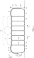
FIG. 2 is a bottom plan view of the sheet ofFIG. 1 showing handles on an underside of the sheet; -
FIG. 3 is a cross-sectional view taken across line 3-3 showing the sheet in a deflated configuration and a patient resting on the sheet; -
FIG. 4 is a cross-sectional view similar toFIG. 3 showing the sheet in an inflated configuration; -
FIG. 5 is a cross-sectional view taken across line 5-5 inFIG. 1 showing the air delivery socks of the sheet in an initial, deflated configuration; -
FIG. 6 is a cross-sectional view similar toFIG. 5 showing one of the air delivery socks inflated and compressing the other air delivery sock; -
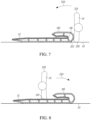
FIG. 7 is a cross-sectional view similar toFIG. 3 showing a patient in a right lateral recumbent and the sheet folded; -
FIG. 8 is a view similar toFIG. 7 showing a patient rolled onto the sheet and positioned in a left lateral recumbent position; -
FIG. 9 is a cross-section view similar toFIG. 7 showing the sheet unfolded and the patient turned to a supine position; -
FIG. 10 is a cross-sectional view similar toFIG. 4 showing the patient on the inflated sheet and a wedge; -
FIG. 11 is a cross-sectional view similar toFIG. 10 showing the sheet shifted on top of the wedge to reposition the patient; -
FIG. 12 is a perspective view of a port of the sheet ofFIG. 1 with a closure strap in an open configuration; -
FIG. 13 is a perspective view similar toFIG. 12 showing the closure strap pulled to constrict the port around the air hose; -
FIG. 14 is a perspective view similar toFIG. 12 showing the closure strap in a closed position which secures the port around the air hose; -
FIG. 15 is a schematic view of a portion of an inflatable patient repositioning sheet and an air supply showing mating snaps of an air hose of the air supply and a closure strap of the sheet; -
FIG. 16 is a schematic view of a portion of another inflatable patient repositioning sheet and an air hose showing mating snaps of the sheet and the air hose; -
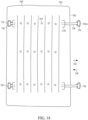
FIG. 17 is a bottom plan view of another inflatable patient repositioning sheet having handles extending laterally outward from the sheet; -
FIG. 18 is a bottom plan view of another inflatable patient repositioning sheet showing handles having storage positions within an outer periphery of the sheet and gripping positions outward from the outer periphery of the sheet; and -
FIG. 19 is a side perspective view of another inflatable patient repositioning sheet showing handles that are movable relative to longitudinal sides of the sheet - With reference to
FIG. 1 , apatient repositioning system 10 is provided thesystem 10 includes an inflatablepatient repositioning sheet 12 and anair supply 14, such as anair pump 16 having ahose 18. Thesheet 12 hasports lateral sides hose 18. Theports strap 30, which may be manually adjusted constrict theports hose 18 and manipulated to secure theports hose 18. InFIG. 1 , thehose 18 is shown secured in theport 22. Theair pump 16 may be turned on to provide air through theport 22 and into thesheet 12. In one form, theair pump 16 is capable of providing air at a pressure in the range of approximately 0,35 to 1,41 kg per square cm (5 to 20 pounds per square inch) to inflate thesheet 12. The air from theair pump 16 inflates thesheet 12 and lifts the patient upward. - The
sheet 12 includes aninflatable body 34 having anupper layer 36 with a high friction surface for resisting slipping of the patient relative to theupper layer 36. Theinflatable body 34 includes alower layer 38 having a plurality ofair exit holes 40 formed therein. The air within thesheet 12 may exit through the air exit holes 40 (seeFIG. 2 ) and create at least a partial air bearing between anunderlying surface 42 and the sheet 12 (seeFIG. 4 ). With thepatient transfer sheet 12 inflated, the weight of thepatient 31 is distributed over a larger area of thesurface 42 than if thepatient 31 were lying directly on thesurface 42. The air bearing formed by the air exiting through theair exit holes 40 and the distribution of the weight of thepatient 31 over a greater surface area reduces frictional resistance to movement of thesheet 12 and patient thereon. In this manner, thesheet 12 and thepatient 31 may be easily shifted in a lateral direction 44 (seeFIG. 4 ), such as from thesurface 42 onto a nearby surface. Thesheet 12 may be used to reposition thepatient 31 in many applications, such as boosting, relocating on a surface, and lateral transfers, all of which are generally deemed to constitute repositioning. For example, the inflatedpatient transfer sheet 12 may be used to transfer thepatient 31 from thesurface 42 of a hospital bed to a surface of a gurney. - Returning to
FIG. 1 , theinflatable body 34 includes a plurality of inner channels in the form oftubes 50 that extend longitudinally along thesheet 12, includinglateral tubes central tubes 56. Thesheet 12 may have one layer oftubes 50 as shown inFIGS. 1 and4 . In other forms, thesheet 12 may have two or more layers oftubes 50. Thetubes 50 may each be formed by portions of the upper andlower layers walls 116 extending longitudinally along thesheet 12. - The
central tubes 56 may haveupper portions 70 that are sized to be smaller thanupper portions 66 of thelateral tubes 52 to provide a recessed patient-receivingregion 60. With reference toFIG. 4 , thepatient 31 is positioned in the patient-receivingregion 60. Thelateral tubes upper portions 66 that extend for adistance 68 above theupper portions 70 of thecentral tubes 56. These tallerupper portions 66 of thelateral tubes patient 31 indirections region 60. - With reference to
FIG. 1 , thesheet 12 includesair delivery socks ports air hose 18 is coupled to theport 22, theair delivery sock 82 receives air from thehose 18 while theair delivery sock 80 generally does not. Conversely, when theair hose 18 is coupled to theport 22, theair delivery sock 80 receives air from thehose 18 while theair delivery sock 82 generally does not. It is possible in some embodiments for an air supply to be connected to each port simultaneously. Thesocks more openings openings sock directions tubes 50. Thesocks socks air supply 14. The air from theair supply 14 travels through thesocks openings tubes 50. In one form, thesocks openings tubes 50. Thesocks FIG. 1 . In other forms, thesocks - With reference to
FIG. 2 , thesheet 12 includes handle straps 100, 102 that are secured, such as by stitches 104, to thelower layer 38. The handles alternately may be stitched to theupper layer 36 or to an edge wall of thesheet 12. The stitches 104 defineintermediate handle portions 106 that are spaced from thelower layer 38. In this manner, a person may insert their fingers into the space between thehandle portions 106 and thelower layer 38 and wrap his fingers around thehandle portion 106 to grasp thehandle portion 106. As shown, twohands 107 are grasping two of thehandle portions 106 in order to pull theinflated sheet 12 and the patient 31 thereon in thedirection 44. - With reference to
FIGS. 3 and4 , thesheet 12 is shown inFIG. 3 in the initial, deflated configuration. Theupper layer 36 may include an upper,high friction layer 110, which may include a microfiber fabric. Theupper layer 36 may also include asubstrate layer 112 that may be include, for example, plastic or nylon. Thelower layer 38 may be include, for example, plastic or nylon. It is believed that the lower layer material may have a kinetic friction force ranging from about 44,48-311,38 N (10-70 lbf) over a cotton hospital bedsheet, this force being the force required to continue moving a 90,72 kg (200 lb). object placed over the material and bedsheet at a constant rate after initiating motion of the object. The upper surface of thehigh friction layer 110 may create a higher frictional force with the patient than the lower surface of thelower layer 38 creates with thesupport surface 42. As shown inFigs. 3 and4 , thewalls 116 connect thesubstrate layer 112 and thelower layer 38. Thewalls 116 may be joined to thesubstrate layer 112 and thelower layer 38 by, for example, stitching or adhesive. In one form, thewalls 116 are folded when thesheet 12 is in the deflated configuration and are substantially planar when the sheet is in the inflated configuration. - With reference to
FIG. 4 , theair supply 14 is providing air to thetubes 50 of thesheet 12 which inflates thesheet 12. With thesheet 12 inflated, thewalls 116separate interiors tubes 50. As shown inFIG. 4 , thesheet 12 includes oppositelateral side walls rear walls 130, 132 (seeFIG. 2 ) that extend laterally. Thelateral side walls rear walls sheet 12 jacks or lifts thepatient 31 to anelevated distance 134 above thesurface 42. - The
substrate layer 112 and thelower layer 38 may be joined together at aseal 140 that connectsouter portions high friction layer 110 may also be joined at anouter portion 146 thereof to theouter portion 142. - With reference to
FIG. 5 , thesocks sheet 12 are shown prior to thehose 18 being inserted to theport 22. Theports openings hose 18. Thesocks tubular side wall 154 and anend wall 156. In the deflated configuration, theside wall 154 includeswall portions initial distance 160. - With reference to
FIG. 6 , thehose 18 has been inserted into theport opening 152 and air is being directed indirection 164 through thesock 82. This expands thesock 82 so that thewall portions sidewall 154 now have an expanded distance 166 therebetween. The expansion of thesock 82 in response to receiving the air from thehose 18 causes theside wall 154 of thesock 82 to contact theside wall 154 of thesock 80 and holdside wall portions sock 80 is held in the deflated configuration when not in use, which flattens out theopenings 86 and makes it difficult for air in thesheet 12 to travel through theopenings 86 and out from theport 20. Further, thesock 82 pushes thesock 80 out of the way to resist thesock 80 from inverting, i.e., traveling outward indirection 176 through theopening 150 as air is supplied to thesock 82. Conversely, if theair hose 18 were inserted intoopening 150 and used to provide air to thesock 80, thesock 80 would expand and compress thesock 82 and keeps thesock 82 from inverting. - Another feature that keeps the
socks directions respective openings connectors connectors connect end portions socks lateral sidewalls connectors sheet 12 may have an anchor member, such as a stitchedconnector 190, connecting theend portions connector 190 resists theend portions directions - With reference to
FIG. 5 , thesocks end portions lateral sidewalls socks socks other sock air supply 14. Further, thesock 82 may be positioned above thesock 80. In this manner, expansion of thesock 82 causes thesock sidewall portion 156 to contact an interior of thesubstrate layer 112 and thesidewall portion 158 to press thesock 80 downward against an interior of thelower layer 38. - A log-rolling approach may be used to position the patient 31 resting on a
surface 42 onto thesheet 12. With reference toFIG. 7 , initially thesheet 12 is positioned on thesupport surface 42 with aportion 210 of thesheet 12 folded onto itself. Afold 212 of thesheet 12 is positioned near the back of thepatient 31 and the patient is positioned in the recumbent position shown inFIG. 7 with aside 220 of the patient 31 on thesurface 42. Next, thepatient 31 is rolled indirection 222 over thesheet portion 210 and onto the opposing recumbent position on thesheet 12 as shown inFIG. 8 with theother side 221 of the patient 31 on thesheet 12. Thesheet portion 210 is then unfolded indirection 224 onto thesupport surface 42 and thepatient 31 is then rolled indirection 224 to a supine position, as shown inFIGS. 8 and9 . With the patient 31 positioned on their back on thesheet 12, the operator may inflate thesheet 12 using theair supply 14. - With reference to
FIGS. 10 and11 , thesheet 12 may also be used with awedge 240 to reposition thepatient 31. For example, thesheet 12 and thewedge 240 may be used to reposition the patient 31 from a supine positon shown inFIG. 10 to a partially recumbent position shown inFIG. 11 . The patient should be log-rolled indirection 242 and the wedge placed underneath them. Thewedge 240 may have a high friction material on theinclined surface 244 and a base 246 may have a high friction material to resist movement of thewedge 240 along thesupport surface 42. - In another embodiment, the
sheet 12 and thewedge 240 may be used to reposition the patient 31 from a supine positon shown inFIG. 10 to a partially recumbent position shown inFIG. 11 . Theinflated transfer sheet 12 may be shifted indirection 242 up an upperinclined surface 244 of thewedge 240. Thewedge 240 may have a low friction material on theinclined surface 244 to permit thesheet 12 to readily slide up thesurface 244 and abase 246 and may have a high friction material to resist movement of thewedge 240 along thesupport surface 42. With reference toFIG. 11 , the sheet has been pulled up along the wedge so that aportion 250 of thesheet 12 is inclined relative to anotherportion 252. As shown inFIG. 11 , the shifting of thesheet 12 along thewedge 240 bends thesheet 12 so that walls 116A, 116B extend transversely to one another. This repositioning of the walls 116A, 116B is permitted by bending of aportion 252 of theupper layer 36. - In one approach, the
wedge 240 and thesheet 12 may be used to reposition the patient 31 when thesheet 12 is in the deflated state. For example, a portion of the patient 31 may be lifted up using the deflatedsheet 12 and one ormore wedges 240 may be positioned below the deflatedsheet 12. The one ormore wedges 240 would then support thepatent 31 in the new position. In one form, the upperinclined surface 244 and the base 246 both have high friction material to resist movement of thesheet 12 relative to thewedge 240, and to resist movement of thewedge 240 relative to thesurface 42. - With reference to
FIG. 12 , theport 22 will be discussed in detail. Theport 20 is substantially identical to theport 22 so that the following description applies to port 20 as well. Theport 22 includes theopening 152 sized to receive theair hose 18. Theport 22 includes asleeve 260 extending about theopening 152 that may be constricted about theair hose 18 to resist exit of air through theopening 152 during inflation of thesheet 12. In one form, thesleeve 260 includes portions of thesubstrate sheet 112 and thelower sheet 38. Thestrap 30 includes anend 262 secured to theupper sheet 36 such as by stitching. Thestrap 30 includes securement portions such as a hook and loop fastener arrangement to releasably secure thestrap 30 to itself. In one approach, thestrap 30 includesloops 264 that releasably engagehooks 266 of thestrap 30 when thestrap 30 has been moved to a closed position. Thestrap 30 extends from theend 262, through anopening 268 in theupper sheet 36, and through a portion of thesleeve 260. As shown inFIG. 12 , aportion 270 of thestrap 30 extends within thesleeve 260. Thestrap 30 exits thesleeve 260 through anopening 272 of theupper sheet 36. Thestrap 30 includes afree end 274 that may be grasped and used to manipulate thestrap 30. In one form, thestrap 30 includes asingle substrate 271 and theloops 264 and hooks 266 are secured to thesingle substrate 271. Thesingle substrate 271 is a single, uninterrupted length of material extending from theend 262 to theend 274. As one example, thesingle substrate 271 is a strip of woven polymer material and thestrap 30 has patches of theloops 264 and hooks 266 sewn onto the strip of material. - With reference to
FIG. 13 , theair hose 18 has been advanced indirection 280 into theopening 152 of theport 22. Theend portion 274 of thestrap 30 has been pulled over indirection 282 which draws aportion 284 of thestrap 30 upward indirection 286 through theopening 272. Because thestrap end 262 is secured to theupper sheet 36, drawing theportion 284 outward from thesleeve 260 constricts thesleeve 260 about theair hose 18. With reference toFIG. 2 , alower portion 290 of thesleeve 260 is shown bunched up in response to thestrap 30 having been used to constrict thesleeve 260. - With reference to
FIG. 14 thestrap 30 has been fully pivoted indirection 282 to the closed position to engage theloops 264 and thehooks 266. The engagement between theloops 264 and thehooks 266 maintains thestrap 30 in the closed configuration and holds thesleeve 260 in the constricted configuration about theair hose 18 so that thesleeve 260 resists air from exiting theopening 152 around theair hose 18. - With reference to
FIG. 15 , another inflatablepatient transfer sheet 400 includes aport 402 having anopening 404 and astrap 406 extending about the opening. Thestrap 406 includeshooks 408 andloops 410 that may be used to releasably secure thestrap 406 in a closed positon and constrict theopening 404. InFIG. 15 , anair pump 420 is provided that includes anair hose 422. Theair hose 422 is sized to fit into theopening 404 of thesheet 400. Theinflatable hose 422 includes a pair ofsnap fastener portions 424 that mate with correspondingsnap fastener positions 426 of thestrap 406. The mating engagement between thesnap fastener portions air hose 422 in theopening 404. - With reference to
FIG. 16 , another inflatablepatient transfer sheet 500 includes aport 502 having anopening 504. Anair hose 506 is sized to be inserted in theopening 504. Theair hose 506 includessnap fastener portions 508 that releasably engagesnap fastener portions 510 of theport 502. In the embodiment ofFIG. 16 , theinflatable sheet 500 does not include a strap for constricting theopening 504. - With reference to
FIG. 17 , another inflatablepatient transfer sheet 600 includes alower layer 602 havingair exit openings 604. The inflatablepatient transfer sheet 600 includes handle straps 606 that are secured to asupport 608 of thesheet 600. The handle straps 606 may be of flexible material and include ahandle portion 610 with anopening 612. - With reference to
FIG. 18 , another inflatablepatient transfer sheet 700 includes alower layer 702 withair exit openings 704 and anouter periphery 706. Thesheet 700 includes handles 710 (one of which is specifically labeled as 710A) having astorage positon 712 within theouter periphery 706 and an operating orgripping position 714 outward from theouter periphery 706. To reposition thehandle 710 from thestorage position 712 to thegripping position 714, a user may grasp thehandle 710 and pull indirection 716. The inflatablepatient transfer sheet 700 may include a resilient member, such as an elastic band 718 (shown as elastically extended forhandle 710A), which returns thehandle 710 indirection 720 after the user releases thehandle 710. Theelastic band 718 thereby keeps thehandle 710 within theouter periphery 706 when not in use. Thesheet 700 may includepockets 724 and eachelastic band 718 may be anchored to thesheet 700 in an associatedpocket 724 so that theelastic band 718 retracts into thepocket 724 when the associatedhandle 710 is not in use. - With reference to
FIG. 19 , another inflatablepatient transfer sheet 800 includes aninflatable body 802 havinglongitudinal sides 804 and handles 806 connected to thelongitudinal sides 804. Thehandles 806 are connected to thelongitudinal sides 804 by anelastic member 808, such as a strap or nylon string. Theelastic member 808 has ends 810, 812 secured to thelongitudinal sides 804.Portions elastic member 808 may extend withinsleeves 820 of thelongitudinal sides 804. Thehandle 806A is shown in a retracted orstorage position 822 and the handle 806B is shown in an operating orgripping position 824. By having an extendedgripping position 824, a user can move the handle(s) 806 closer to their body so that the user has a better mechanical advantage before using the handle(s) 806 to reposition thesheet 800. - It is thus seen that a patient repositioning sheet is provided.
Claims (13)
- An inflatable patient repositioning sheet (12) comprising:an inflatable body (34);a first air supply port (20) and a second air supply port (22) of the inflatable body (34);a first air delivery sock (80) and a second air delivery sock (82) in the inflatable body (34), each air delivery sock (80, 82) having a first end portion and a second end portion, wherein the first end portion of each air delivery sock (80, 82) is in communication with one of the air supply ports (20, 22) and the second end portion is opposite the first end portion;at least one anchor member (180, 182) resisting movement of the second end portion of each air delivery sock (80, 82) toward the first end portion of the air delivery sock (80, 82) in response to air being supplied into the other of the air delivery socks (80, 82) and securing the second end portions of the air delivery socks (80, 82) to one another.
- The inflatable patient repositioning sheet (12) of claim 1 wherein at least one anchor member includes a pair of anchor members securing the second end portions of the air delivery socks (80, 82) to opposite lateral side walls (126, 128) of the inflatable body (34).
- The inflatable patient repositioning sheet (12) of claim 1 wherein the inflatable body (34) includes an upper patient support surface (42) and a lower sliding surface, wherein one of the air delivery socks (80, 82) is above the other of the air delivery socks (80, 82).
- The inflatable patient repositioning sheet (12) of claim 1 wherein the inflatable body (34) includes opposite lateral side walls (126, 128) and the air delivery socks (80, 82) are oriented to extend laterally between the side walls (126, 128) and overlap with one another in the lateral direction.
- The inflatable patient repositioning sheet (12) of claim 1 wherein the body (34) includes a plurality of longitudinal tubes (50) in communication with the air delivery socks (80, 82).
- The inflatable patient repositioning sheet (12) of claim 1 wherein the inflatable body (34) includes a bottom portion having a plurality of through openings (604) that permit air to exit the inflatable body (34).
- The inflatable patient repositioning sheet (12) of claim 1 further comprising handles (806) connected to the inflatable body (34).
- The inflatable patient repositioning sheet (12) of claim 7 further comprising elastic members (808) connecting the handles to the inflatable body (34).
- The inflatable patient repositioning sheet (12) of claim 1 wherein the air supply ports (20, 22) each include an opening (150, 152) sized to receive an air supply hose (18) and a flexible closure member (30) permitting constriction of the opening (150, 152) about the air supply hose (18), the closure member (30) having a first end secured to the inflatable body (34) and a second end opposite the first end; and
a pair of securement portions of the closure member (30) adapted to be releasably engaged together to hold the closure member (30) in a looped configuration about the air supply hose (18). - The inflatable patient repositioning sheet (12) of claim 1 wherein the first air delivery sock (80) and the second air delivery sock (82) are extending in proximity to one another in the inflatable body (34) and wherein each air delivery sock (80, 82) is adapted to inflate in response to the air delivery sock (80, 82) receiving air from an air supply and press against the other air delivery sock (80, 82).
- A system including the inflatable patient repositioning sheet (12) of claim 1 and an air supply (14), the air supply (14) including a hose (18) sized to extend through one of the air supply ports (20, 22) of the inflatable body (34) and an air pump.
- A method comprising:providing the inflatable patient repositioning sheet (12) of claim 1; andpositioning a patient on the inflatable patient repositioning sheet (12).
- The method of claim 12 further comprising:connecting an air supply to one of the air supply ports (20, 22); andinflating the inflatable patient repositioning sheet (12).
Priority Applications (1)
| Application Number | Priority Date | Filing Date | Title |
|---|---|---|---|
| EP23180506.0A EP4233821A3 (en) | 2017-03-03 | 2018-02-13 | Inflatable patient repositioning sheet |
Applications Claiming Priority (2)
| Application Number | Priority Date | Filing Date | Title |
|---|---|---|---|
| US15/449,560 US10828216B2 (en) | 2017-03-03 | 2017-03-03 | Inflatable patient repositioning sheet |
| PCT/US2018/017948 WO2018160349A1 (en) | 2017-03-03 | 2018-02-13 | Inflatable patient repositioning sheet |
Related Child Applications (2)
| Application Number | Title | Priority Date | Filing Date |
|---|---|---|---|
| EP23180506.0A Division EP4233821A3 (en) | 2017-03-03 | 2018-02-13 | Inflatable patient repositioning sheet |
| EP23180506.0A Division-Into EP4233821A3 (en) | 2017-03-03 | 2018-02-13 | Inflatable patient repositioning sheet |
Publications (3)
| Publication Number | Publication Date |
|---|---|
| EP3589255A1 EP3589255A1 (en) | 2020-01-08 |
| EP3589255A4 EP3589255A4 (en) | 2020-12-16 |
| EP3589255B1 true EP3589255B1 (en) | 2023-08-02 |
Family
ID=63357101
Family Applications (2)
| Application Number | Title | Priority Date | Filing Date |
|---|---|---|---|
| EP23180506.0A Pending EP4233821A3 (en) | 2017-03-03 | 2018-02-13 | Inflatable patient repositioning sheet |
| EP18761710.5A Active EP3589255B1 (en) | 2017-03-03 | 2018-02-13 | Inflatable patient repositioning sheet |
Family Applications Before (1)
| Application Number | Title | Priority Date | Filing Date |
|---|---|---|---|
| EP23180506.0A Pending EP4233821A3 (en) | 2017-03-03 | 2018-02-13 | Inflatable patient repositioning sheet |
Country Status (5)
| Country | Link |
|---|---|
| US (1) | US10828216B2 (en) |
| EP (2) | EP4233821A3 (en) |
| CN (1) | CN110582258B (en) |
| CA (2) | CA3290140A1 (en) |
| WO (1) | WO2018160349A1 (en) |
Families Citing this family (19)
| Publication number | Priority date | Publication date | Assignee | Title |
|---|---|---|---|---|
| CA2872583C (en) | 2013-11-27 | 2022-06-07 | Sage Products, Llc | Apparatus and system for turning and positioning a patient |
| US10765576B2 (en) | 2015-08-18 | 2020-09-08 | Sage Products, Llc | Apparatus and system for boosting, transferring, turning and positioning a patient |
| US9849053B2 (en) | 2015-08-18 | 2017-12-26 | Sage Products, Llc | Apparatus and system for boosting, transferring, turning and positioning a patient |
| US10772778B2 (en) | 2017-04-25 | 2020-09-15 | Medline Industries, Inc. | Patient repositioning sheet and sling |
| CA3069729A1 (en) | 2017-06-13 | 2018-12-20 | Sage Products, Llc | Patient positioning and support system |
| AU2018318107B2 (en) * | 2017-08-14 | 2020-09-10 | D.T. Davis Enterprises, Ltd. (D/B/A Hovertech International) | Single port lateral transfer device and rotational positioning device combination |
| CA3075999A1 (en) * | 2017-09-19 | 2019-03-28 | Sage Products, Llc | Apparatus and method for positioning a patient |
| US11246775B2 (en) | 2017-12-28 | 2022-02-15 | Stryker Corporation | Patient turning device for a patient support apparatus |
| WO2020041493A1 (en) | 2018-08-21 | 2020-02-27 | Sage Products, Llc | Systems and methods for lifting and positioning a patient |
| US10858023B2 (en) | 2019-03-15 | 2020-12-08 | Medline Industries, Inc. | Mattress air supply device cart and methods of use |
| USD914217S1 (en) | 2019-03-15 | 2021-03-23 | Medline Industries, Inc. | Cart |
| WO2020204918A1 (en) * | 2019-04-03 | 2020-10-08 | Intensive Therapeutics, Inc. | Prone-to-supine transfer mattress |
| US11331235B2 (en) * | 2019-09-13 | 2022-05-17 | Medline Industries, Lp | Patient repositioning sheet, system, and method |
| US11737939B2 (en) * | 2019-10-23 | 2023-08-29 | D.T. Davis Enterprises, Ltd. | System and method for patient positioning and offloading |
| EP4329696A1 (en) * | 2021-04-22 | 2024-03-06 | D.T. Davis Enterprises, Ltd. (d/b/a Hovertech International) | Trendelenburg patient positioning device |
| US11890240B2 (en) | 2021-04-30 | 2024-02-06 | Sage Products, Llc | Method and device for turning and positioning a patient using fillable chambers |
| US20240307728A1 (en) * | 2023-03-17 | 2024-09-19 | Slick Slide LLC | Open-cell airbag landing device having a closed-cell foundation |
| US12508182B2 (en) | 2023-04-26 | 2025-12-30 | Sage Products, Llc | Sheet assembly for positioning a patient |
| US12564530B2 (en) * | 2023-09-06 | 2026-03-03 | Medline Industries Lp | Inflatable patient positioner with selectively engaging surface gripping zones |
Family Cites Families (103)
| Publication number | Priority date | Publication date | Assignee | Title |
|---|---|---|---|---|
| US1006477A (en) | 1908-04-30 | 1911-10-24 | Laval Steam Turbine Co | Steam-power plant and the like. |
| US1003968A (en) | 1911-02-06 | 1911-09-19 | William J Paul | Furnace for perfecting combustion. |
| US1011780A (en) | 1911-02-08 | 1911-12-12 | Joseph F Hanrahan | Drier. |
| US1018295A (en) | 1911-03-21 | 1912-02-20 | Jennie Burr | Ironing-board. |
| US1039861A (en) | 1911-06-08 | 1912-10-01 | Mary H King | Process of making nickel salts and recovering the acid used. |
| US1024499A (en) | 1911-09-26 | 1912-04-30 | Harry T Coldwell | Tea-harvester. |
| US5067189A (en) | 1990-04-11 | 1991-11-26 | Weedling Robert E | Air chamber type patient mover air pallet with multiple control features |
| US5442821A (en) | 1993-09-03 | 1995-08-22 | Weeks; Carole G. | Patient transfer sling |
| US5561873A (en) * | 1994-07-15 | 1996-10-08 | Patient Transfer Systems, Inc. | Air chamber-type patient mover air pallet with multiple control features |
| US6073291A (en) * | 1997-02-21 | 2000-06-13 | Davis; David T. | Inflatable medical patient transfer apparatus |
| US5926883A (en) * | 1997-08-13 | 1999-07-27 | Gaymar Industries, Inc. | Apparatus and method for controlling a patient positioned upon a cushion |
| GB9722359D0 (en) | 1997-10-24 | 1997-12-17 | Mangar International Ltd | Patient support apparatus |
| US20050028273A1 (en) | 2001-05-11 | 2005-02-10 | Weedling Robert E. | Patient transfer mattress having connectable segments |
| US7739758B2 (en) | 2001-05-11 | 2010-06-22 | Patient Transfer Systems, Inc | Support PAD for a patient transfer mattress |
| US7900299B2 (en) | 2001-05-11 | 2011-03-08 | Weedling Robert E | Patient transfer device having inflatable air mattress |
| CA2504763C (en) * | 2002-11-12 | 2008-06-03 | Gray Tek, Inc. | Material mover having a fluid film reservoir |
| US6898809B2 (en) | 2003-08-11 | 2005-05-31 | Woodlark Circle, Inc. | Air mattress with single perimeter seam |
| US7712170B2 (en) | 2003-08-11 | 2010-05-11 | Woodlark Circle, Inc. | Single patient, personal use air mattress having a single perimeter seam |
| NZ549836A (en) | 2004-03-02 | 2009-05-31 | Patient Transfer Systems Inc | Patient transfer device having inclined upper surface |
| US7243382B2 (en) | 2004-05-06 | 2007-07-17 | Weedling Robert E | Patient transfer mattress having side pull straps |
| US7975330B2 (en) | 2009-09-30 | 2011-07-12 | Hill-Rom Services, Inc. | Occupant transfer topper |
| US7340785B2 (en) * | 2004-07-02 | 2008-03-11 | Weedling Robert E | Sanitary liner for a patient transfer mattress |
| US7107641B2 (en) * | 2004-07-28 | 2006-09-19 | Davis David T | Double chambered air mattress |
| US7376995B2 (en) | 2004-07-28 | 2008-05-27 | Woodlark Circle, Inc. | Double chambered air mattress |
| US8413271B2 (en) | 2004-10-29 | 2013-04-09 | Stryker Corporation | Patient support apparatus |
| US7028350B1 (en) | 2004-12-07 | 2006-04-18 | Woodlark Circle, Inc. | Lifting cushion and method for transferring a patient from a chair |
| US9125777B2 (en) | 2005-01-14 | 2015-09-08 | Sage Products, Llc | Body transport apparatus |
| US7735164B1 (en) | 2005-01-14 | 2010-06-15 | Smart Medical Technology, Inc. | Disposable patient transfer mattress |
| US9241580B2 (en) | 2005-01-14 | 2016-01-26 | Sage Products, Llc | Body transport apparatus with integrated handles |
| US8276222B1 (en) | 2005-01-14 | 2012-10-02 | Smart Medical Technology, Inc. | Patient transfer kit |
| US7114204B2 (en) | 2005-01-14 | 2006-10-03 | Smart Medical Technology, Inc. | Method and apparatus for transferring patients |
| US20060282946A1 (en) * | 2005-06-15 | 2006-12-21 | Meyer Matthew E | Patient transfer device |
| US7464422B2 (en) | 2005-07-07 | 2008-12-16 | Bobie Kenneth Townsend | Inflatable device for turning people on their side and back again |
| US7337477B2 (en) | 2005-09-14 | 2008-03-04 | Stretchair Patient Transfer Systems, Inc. | Method and apparatus for patient transfer |
| US7266852B2 (en) | 2005-10-31 | 2007-09-11 | Woodlark Circle, Inc. | Inflatable transfer mattress |
| EP2019786B1 (en) | 2006-05-08 | 2014-01-08 | Stryker Corporation | Air bearing pallet |
| EP2046259B1 (en) | 2006-06-28 | 2014-07-02 | Stryker Corporation | Patient support |
| JP4959250B2 (en) | 2006-08-04 | 2012-06-20 | 株式会社モリトー | Sling sheet |
| US7681262B2 (en) | 2006-11-01 | 2010-03-23 | Weedling Robert E | Patient incline device having centerline spinal support |
| US7467431B2 (en) | 2006-11-01 | 2008-12-23 | Weedling Robert E | Patient incline device having centerline spinal support |
| US8006333B2 (en) | 2006-11-16 | 2011-08-30 | Stryker Corporation | Patient support surface with turn-assist |
| US8201292B2 (en) | 2006-11-16 | 2012-06-19 | Stryker Corporation | Patient support surface with turn-assist |
| US20080209630A1 (en) | 2007-01-16 | 2008-09-04 | Kci Licensing, Inc. | Patient Repositioning System |
| US7650654B2 (en) | 2007-03-05 | 2010-01-26 | Stryker Corporation | Transfer device |
| US7712171B2 (en) | 2007-04-25 | 2010-05-11 | Hill-Rom Services, Inc. | Patient support including turn assist, low air loss, or integrated lateral transfer |
| GB0709328D0 (en) | 2007-05-15 | 2007-06-20 | Genie Care | Turning platform |
| US7627910B2 (en) | 2007-05-22 | 2009-12-08 | Woodlark Circle, Inc. | Partially deflatable transfer mattress and method for transporting a patient in comfort |
| US20100229298A1 (en) | 2009-03-13 | 2010-09-16 | Woodlark Circle, Inc. | Transfer mattress with inflatable foot rest |
| US8646124B2 (en) | 2009-05-13 | 2014-02-11 | Stryker Corporation | Transport apparatus |
| US8234727B2 (en) * | 2009-09-04 | 2012-08-07 | Stryker Corporation | Patient transfer device |
| US7849533B1 (en) | 2009-09-30 | 2010-12-14 | Hill-Rom Services, Inc. | Occupant transfer sheet |
| US9420895B2 (en) | 2009-12-17 | 2016-08-23 | Stryker Corporation | Patient support |
| EP2531159B1 (en) | 2010-02-05 | 2018-01-24 | Stryker Corporation | Patient/invalid support |
| CA2692894C (en) | 2010-02-12 | 2017-06-27 | Bhm Medical Inc. | Lift apparatus and system |
| CA2693703A1 (en) | 2010-02-18 | 2011-08-18 | Bhm Medical Inc. | Patient lifting machine |
| NL2005398C2 (en) | 2010-09-27 | 2012-03-28 | Handicare Stairlifts B V | Friction drive lift. |
| US8984681B2 (en) | 2011-01-26 | 2015-03-24 | Sage Products, Llc | Apparatus and system for turning and positioning a patient |
| EP2667836B1 (en) | 2011-01-26 | 2017-05-17 | Sage Products, LLC | Apparatus, system, and method for turning and positioning a patient |
| US8789533B2 (en) | 2011-01-26 | 2014-07-29 | Sage Products, Llc | Method for turning and positioning a patient |
| USD690424S1 (en) | 2011-01-26 | 2013-09-24 | Sage Products, Inc. | Set of components for a patient repositioning system |
| US8850634B2 (en) | 2011-01-26 | 2014-10-07 | Sage Products, Llc | Apparatus and system for turning and positioning a patient |
| US9414977B2 (en) | 2011-01-26 | 2016-08-16 | Sage Products, Llc | Apparatus and system for turning and positioning a patient |
| BR112013020804A2 (en) | 2011-02-17 | 2018-07-10 | Woodlark Circle Inc | inflatable net and method for patient positioning |
| WO2012170934A2 (en) | 2011-06-08 | 2012-12-13 | Sage Products, Inc. | Apparatus and system for turning and positioning a patient |
| CN108309629A (en) * | 2011-06-16 | 2018-07-24 | 东莞沛佳医疗保健科技有限公司 | Medical air-inflated mattress, container or bedpan contained structure and its inflation and deflating method |
| EP2731567B1 (en) | 2011-07-13 | 2016-12-14 | Stryker Corporation | Patient/invalid handling support |
| US9421140B2 (en) | 2011-07-19 | 2016-08-23 | Arjohuntleigh Magog Inc. | Patient/invalid lift with support line bearing power and data communications |
| US20130042414A1 (en) | 2011-08-17 | 2013-02-21 | Stryker Corporation | Air inlet for patient support device |
| US9222498B2 (en) | 2011-09-08 | 2015-12-29 | Arjohuntleigh Magog, Inc. | Lifting bar and lifting bar connector |
| CN104105467B (en) | 2011-12-09 | 2017-07-28 | 而久亨特立公司 | patient transfer device |
| US9381125B2 (en) | 2012-03-02 | 2016-07-05 | Stryker Corporation | Patient support |
| EP2641578B1 (en) | 2012-03-22 | 2016-01-20 | Arjo Hospital Equipment AB | Patient sling |
| US9132052B2 (en) | 2012-04-12 | 2015-09-15 | Sage Products, Llc | Apparatus and method for positioning a seated patient |
| US9101521B2 (en) | 2012-04-16 | 2015-08-11 | Cega Innovations, Llc | Systems, methods and transfer sheets for transferring patients |
| US8782826B2 (en) | 2012-04-16 | 2014-07-22 | Cega Innovations, Llc | System and method for transferring patients |
| US9114050B2 (en) | 2012-04-16 | 2015-08-25 | Cega Innovations, Llc | Systems and methods for transferring patients |
| US20140007353A1 (en) | 2012-04-30 | 2014-01-09 | Stryker Corporation | Patient turner |
| BR112015017635A2 (en) | 2013-02-18 | 2017-07-11 | Us Pacific Nonwovens Industry Ltd | manual sling sling |
| US9278038B2 (en) | 2013-08-28 | 2016-03-08 | Mary Masucci | Supporting and maneuverable sling for bed-constrained patients |
| US9782312B2 (en) | 2013-09-05 | 2017-10-10 | Stryker Corporation | Patient support |
| US9554956B2 (en) * | 2013-10-10 | 2017-01-31 | Vision of Labor, LLC | Patient turning and positioning system device |
| CA2872583C (en) | 2013-11-27 | 2022-06-07 | Sage Products, Llc | Apparatus and system for turning and positioning a patient |
| TWI583367B (en) | 2014-05-23 | 2017-05-21 | 艾爾波公司 | Patient transfer device having inflatable air mattress and fixedly-attached sling sheet |
| US9693919B2 (en) | 2014-10-07 | 2017-07-04 | Medline Industries, Inc. | Patient transport device with strap concealment apparatus and corresponding methods |
| US10039680B2 (en) | 2014-10-27 | 2018-08-07 | Nurses Care, LLC | Body sling and patient handling sheets |
| US9849053B2 (en) | 2015-08-18 | 2017-12-26 | Sage Products, Llc | Apparatus and system for boosting, transferring, turning and positioning a patient |
| US10765576B2 (en) | 2015-08-18 | 2020-09-08 | Sage Products, Llc | Apparatus and system for boosting, transferring, turning and positioning a patient |
| EP3162347A1 (en) | 2015-11-02 | 2017-05-03 | Sage Products LLC | Apparatus and system for lifting, moving, turning, and positioning a patient |
| US10905609B2 (en) | 2015-11-20 | 2021-02-02 | Stryker Corporation | Patient support systems and methods for assisting caregivers with patient care |
| US10588800B2 (en) | 2015-12-01 | 2020-03-17 | Sage Products, Llc | System and method for moving, turning, and positioning a patient |
| US11020295B2 (en) | 2015-12-22 | 2021-06-01 | Stryker Corporation | Patient support systems and methods for assisting caregivers with patient care |
| CN108697326B (en) | 2016-01-28 | 2022-08-02 | D.T.戴维斯企业有限公司 | Inflatable support |
| EP3454810B1 (en) | 2016-05-13 | 2020-05-06 | Sage Products, LLC | Patient transport apparatus |
| US10285888B2 (en) * | 2017-01-17 | 2019-05-14 | Caremed Supply Inc. | Inflatable stretcher |
| US10772778B2 (en) | 2017-04-25 | 2020-09-15 | Medline Industries, Inc. | Patient repositioning sheet and sling |
| CA3069729A1 (en) | 2017-06-13 | 2018-12-20 | Sage Products, Llc | Patient positioning and support system |
| CA3075999A1 (en) | 2017-09-19 | 2019-03-28 | Sage Products, Llc | Apparatus and method for positioning a patient |
| CN209253421U (en) | 2017-09-27 | 2019-08-16 | 瑟格创新有限公司 | Patient transfer apparatus |
| JP7266309B2 (en) | 2017-09-27 | 2023-04-28 | シガ イノベーションズ, インコーポレイテッド | air bearing patient transfer system |
| US11173085B2 (en) | 2017-12-28 | 2021-11-16 | Stryker Corporation | Mattress cover for a mattress providing rotation therapy to a patient |
| US11246775B2 (en) | 2017-12-28 | 2022-02-15 | Stryker Corporation | Patient turning device for a patient support apparatus |
| US12023288B2 (en) | 2018-01-17 | 2024-07-02 | Sage Products, Llc | Patient handling apparatus and method of use |
| US11173087B2 (en) | 2018-02-01 | 2021-11-16 | Stryker Corporation | System and methods for supporting and positioning a person |
-
2017
- 2017-03-03 US US15/449,560 patent/US10828216B2/en active Active
-
2018
- 2018-02-13 WO PCT/US2018/017948 patent/WO2018160349A1/en not_active Ceased
- 2018-02-13 EP EP23180506.0A patent/EP4233821A3/en active Pending
- 2018-02-13 CA CA3290140A patent/CA3290140A1/en active Pending
- 2018-02-13 CA CA3054795A patent/CA3054795A1/en active Pending
- 2018-02-13 EP EP18761710.5A patent/EP3589255B1/en active Active
- 2018-02-13 CN CN201880026891.4A patent/CN110582258B/en active Active
Also Published As
| Publication number | Publication date |
|---|---|
| EP4233821A3 (en) | 2024-01-31 |
| CA3290140A1 (en) | 2025-11-29 |
| US10828216B2 (en) | 2020-11-10 |
| EP3589255A4 (en) | 2020-12-16 |
| CA3054795A1 (en) | 2018-09-07 |
| CN110582258A (en) | 2019-12-17 |
| CN110582258B (en) | 2022-07-08 |
| US20180250180A1 (en) | 2018-09-06 |
| WO2018160349A1 (en) | 2018-09-07 |
| EP3589255A1 (en) | 2020-01-08 |
| EP4233821A2 (en) | 2023-08-30 |
Similar Documents
| Publication | Publication Date | Title |
|---|---|---|
| US10828216B2 (en) | Inflatable patient repositioning sheet | |
| US11654063B2 (en) | System and method for moving, turning, and positioning a patient | |
| US12115096B2 (en) | Patient positioning system | |
| US10064770B2 (en) | Patient turning and positioning system device | |
| US12220366B2 (en) | Apparatus and system for boosting, transferring, turning and positioning a patient | |
| US9066609B2 (en) | Infant patient transfer device | |
| CN109549804A (en) | Air bearing patient's transfer system | |
| US4807606A (en) | Therapeutic appliance for improving functions of hand fingers | |
| US10285888B2 (en) | Inflatable stretcher | |
| US12208044B2 (en) | Patient repositioning sheet, system, and method | |
| US20050246834A1 (en) | Patient transfer mattress having side pull straps | |
| US20180221192A1 (en) | Shoulder and Arm Support | |
| CN110913821A (en) | air pressurized equipment | |
| CN204682591U (en) | Military anti shock trousers | |
| JP3013787U (en) | Rehabilitation belt | |
| CN219501398U (en) | Multifunctional dual-purpose movable turning-over sheet | |
| CN216221946U (en) | A post-operative multi-purpose non-slip abdominal belt | |
| CA2777157C (en) | Patient positioning device |
Legal Events
| Date | Code | Title | Description |
|---|---|---|---|
| STAA | Information on the status of an ep patent application or granted ep patent |
Free format text: STATUS: THE INTERNATIONAL PUBLICATION HAS BEEN MADE |
|
| PUAI | Public reference made under article 153(3) epc to a published international application that has entered the european phase |
Free format text: ORIGINAL CODE: 0009012 |
|
| STAA | Information on the status of an ep patent application or granted ep patent |
Free format text: STATUS: REQUEST FOR EXAMINATION WAS MADE |
|
| 17P | Request for examination filed |
Effective date: 20190916 |
|
| AK | Designated contracting states |
Kind code of ref document: A1 Designated state(s): AL AT BE BG CH CY CZ DE DK EE ES FI FR GB GR HR HU IE IS IT LI LT LU LV MC MK MT NL NO PL PT RO RS SE SI SK SM TR |
|
| AX | Request for extension of the european patent |
Extension state: BA ME |
|
| DAV | Request for validation of the european patent (deleted) | ||
| DAX | Request for extension of the european patent (deleted) | ||
| A4 | Supplementary search report drawn up and despatched |
Effective date: 20201113 |
|
| RIC1 | Information provided on ipc code assigned before grant |
Ipc: A61G 7/10 20060101ALI20201109BHEP Ipc: A61G 1/01 20060101ALI20201109BHEP Ipc: A61G 7/008 20060101AFI20201109BHEP Ipc: A47C 27/08 20060101ALI20201109BHEP Ipc: A61G 7/00 20060101ALI20201109BHEP |
|
| GRAP | Despatch of communication of intention to grant a patent |
Free format text: ORIGINAL CODE: EPIDOSNIGR1 |
|
| STAA | Information on the status of an ep patent application or granted ep patent |
Free format text: STATUS: GRANT OF PATENT IS INTENDED |
|
| RIC1 | Information provided on ipc code assigned before grant |
Ipc: A61G 7/00 20060101ALI20230131BHEP Ipc: A61G 1/01 20060101ALI20230131BHEP Ipc: A61G 7/10 20060101ALI20230131BHEP Ipc: A47C 27/08 20060101ALI20230131BHEP Ipc: A61G 7/008 20060101AFI20230131BHEP |
|
| INTG | Intention to grant announced |
Effective date: 20230303 |
|
| GRAS | Grant fee paid |
Free format text: ORIGINAL CODE: EPIDOSNIGR3 |
|
| GRAA | (expected) grant |
Free format text: ORIGINAL CODE: 0009210 |
|
| STAA | Information on the status of an ep patent application or granted ep patent |
Free format text: STATUS: THE PATENT HAS BEEN GRANTED |
|
| AK | Designated contracting states |
Kind code of ref document: B1 Designated state(s): AL AT BE BG CH CY CZ DE DK EE ES FI FR GB GR HR HU IE IS IT LI LT LU LV MC MK MT NL NO PL PT RO RS SE SI SK SM TR |
|
| REG | Reference to a national code |
Ref country code: GB Ref legal event code: FG4D |
|
| REG | Reference to a national code |
Ref country code: CH Ref legal event code: EP |
|
| REG | Reference to a national code |
Ref country code: DE Ref legal event code: R096 Ref document number: 602018054561 Country of ref document: DE |
|
| REG | Reference to a national code |
Ref country code: IE Ref legal event code: FG4D |
|
| REG | Reference to a national code |
Ref country code: NL Ref legal event code: FP |
|
| REG | Reference to a national code |
Ref country code: LT Ref legal event code: MG9D |
|
| REG | Reference to a national code |
Ref country code: AT Ref legal event code: MK05 Ref document number: 1593843 Country of ref document: AT Kind code of ref document: T Effective date: 20230802 |
|
| PG25 | Lapsed in a contracting state [announced via postgrant information from national office to epo] |
Ref country code: GR Free format text: LAPSE BECAUSE OF FAILURE TO SUBMIT A TRANSLATION OF THE DESCRIPTION OR TO PAY THE FEE WITHIN THE PRESCRIBED TIME-LIMIT Effective date: 20231103 |
|
| PG25 | Lapsed in a contracting state [announced via postgrant information from national office to epo] |
Ref country code: IS Free format text: LAPSE BECAUSE OF FAILURE TO SUBMIT A TRANSLATION OF THE DESCRIPTION OR TO PAY THE FEE WITHIN THE PRESCRIBED TIME-LIMIT Effective date: 20231202 |
|
| PG25 | Lapsed in a contracting state [announced via postgrant information from national office to epo] |
Ref country code: SE Free format text: LAPSE BECAUSE OF FAILURE TO SUBMIT A TRANSLATION OF THE DESCRIPTION OR TO PAY THE FEE WITHIN THE PRESCRIBED TIME-LIMIT Effective date: 20230802 Ref country code: RS Free format text: LAPSE BECAUSE OF FAILURE TO SUBMIT A TRANSLATION OF THE DESCRIPTION OR TO PAY THE FEE WITHIN THE PRESCRIBED TIME-LIMIT Effective date: 20230802 Ref country code: PT Free format text: LAPSE BECAUSE OF FAILURE TO SUBMIT A TRANSLATION OF THE DESCRIPTION OR TO PAY THE FEE WITHIN THE PRESCRIBED TIME-LIMIT Effective date: 20231204 Ref country code: NO Free format text: LAPSE BECAUSE OF FAILURE TO SUBMIT A TRANSLATION OF THE DESCRIPTION OR TO PAY THE FEE WITHIN THE PRESCRIBED TIME-LIMIT Effective date: 20231102 Ref country code: LV Free format text: LAPSE BECAUSE OF FAILURE TO SUBMIT A TRANSLATION OF THE DESCRIPTION OR TO PAY THE FEE WITHIN THE PRESCRIBED TIME-LIMIT Effective date: 20230802 Ref country code: LT Free format text: LAPSE BECAUSE OF FAILURE TO SUBMIT A TRANSLATION OF THE DESCRIPTION OR TO PAY THE FEE WITHIN THE PRESCRIBED TIME-LIMIT Effective date: 20230802 Ref country code: IS Free format text: LAPSE BECAUSE OF FAILURE TO SUBMIT A TRANSLATION OF THE DESCRIPTION OR TO PAY THE FEE WITHIN THE PRESCRIBED TIME-LIMIT Effective date: 20231202 Ref country code: HR Free format text: LAPSE BECAUSE OF FAILURE TO SUBMIT A TRANSLATION OF THE DESCRIPTION OR TO PAY THE FEE WITHIN THE PRESCRIBED TIME-LIMIT Effective date: 20230802 Ref country code: GR Free format text: LAPSE BECAUSE OF FAILURE TO SUBMIT A TRANSLATION OF THE DESCRIPTION OR TO PAY THE FEE WITHIN THE PRESCRIBED TIME-LIMIT Effective date: 20231103 Ref country code: FI Free format text: LAPSE BECAUSE OF FAILURE TO SUBMIT A TRANSLATION OF THE DESCRIPTION OR TO PAY THE FEE WITHIN THE PRESCRIBED TIME-LIMIT Effective date: 20230802 Ref country code: AT Free format text: LAPSE BECAUSE OF FAILURE TO SUBMIT A TRANSLATION OF THE DESCRIPTION OR TO PAY THE FEE WITHIN THE PRESCRIBED TIME-LIMIT Effective date: 20230802 |
|
| PG25 | Lapsed in a contracting state [announced via postgrant information from national office to epo] |
Ref country code: PL Free format text: LAPSE BECAUSE OF FAILURE TO SUBMIT A TRANSLATION OF THE DESCRIPTION OR TO PAY THE FEE WITHIN THE PRESCRIBED TIME-LIMIT Effective date: 20230802 |
|
| PG25 | Lapsed in a contracting state [announced via postgrant information from national office to epo] |
Ref country code: ES Free format text: LAPSE BECAUSE OF FAILURE TO SUBMIT A TRANSLATION OF THE DESCRIPTION OR TO PAY THE FEE WITHIN THE PRESCRIBED TIME-LIMIT Effective date: 20230802 |
|
| PG25 | Lapsed in a contracting state [announced via postgrant information from national office to epo] |
Ref country code: SM Free format text: LAPSE BECAUSE OF FAILURE TO SUBMIT A TRANSLATION OF THE DESCRIPTION OR TO PAY THE FEE WITHIN THE PRESCRIBED TIME-LIMIT Effective date: 20230802 Ref country code: RO Free format text: LAPSE BECAUSE OF FAILURE TO SUBMIT A TRANSLATION OF THE DESCRIPTION OR TO PAY THE FEE WITHIN THE PRESCRIBED TIME-LIMIT Effective date: 20230802 Ref country code: ES Free format text: LAPSE BECAUSE OF FAILURE TO SUBMIT A TRANSLATION OF THE DESCRIPTION OR TO PAY THE FEE WITHIN THE PRESCRIBED TIME-LIMIT Effective date: 20230802 Ref country code: EE Free format text: LAPSE BECAUSE OF FAILURE TO SUBMIT A TRANSLATION OF THE DESCRIPTION OR TO PAY THE FEE WITHIN THE PRESCRIBED TIME-LIMIT Effective date: 20230802 Ref country code: DK Free format text: LAPSE BECAUSE OF FAILURE TO SUBMIT A TRANSLATION OF THE DESCRIPTION OR TO PAY THE FEE WITHIN THE PRESCRIBED TIME-LIMIT Effective date: 20230802 Ref country code: CZ Free format text: LAPSE BECAUSE OF FAILURE TO SUBMIT A TRANSLATION OF THE DESCRIPTION OR TO PAY THE FEE WITHIN THE PRESCRIBED TIME-LIMIT Effective date: 20230802 Ref country code: SK Free format text: LAPSE BECAUSE OF FAILURE TO SUBMIT A TRANSLATION OF THE DESCRIPTION OR TO PAY THE FEE WITHIN THE PRESCRIBED TIME-LIMIT Effective date: 20230802 |
|
| REG | Reference to a national code |
Ref country code: DE Ref legal event code: R097 Ref document number: 602018054561 Country of ref document: DE |
|
| PG25 | Lapsed in a contracting state [announced via postgrant information from national office to epo] |
Ref country code: IT Free format text: LAPSE BECAUSE OF FAILURE TO SUBMIT A TRANSLATION OF THE DESCRIPTION OR TO PAY THE FEE WITHIN THE PRESCRIBED TIME-LIMIT Effective date: 20230802 |
|
| PLBE | No opposition filed within time limit |
Free format text: ORIGINAL CODE: 0009261 |
|
| STAA | Information on the status of an ep patent application or granted ep patent |
Free format text: STATUS: NO OPPOSITION FILED WITHIN TIME LIMIT |
|
| 26N | No opposition filed |
Effective date: 20240503 |
|
| PG25 | Lapsed in a contracting state [announced via postgrant information from national office to epo] |
Ref country code: SI Free format text: LAPSE BECAUSE OF FAILURE TO SUBMIT A TRANSLATION OF THE DESCRIPTION OR TO PAY THE FEE WITHIN THE PRESCRIBED TIME-LIMIT Effective date: 20230802 |
|
| PG25 | Lapsed in a contracting state [announced via postgrant information from national office to epo] |
Ref country code: MC Free format text: LAPSE BECAUSE OF FAILURE TO SUBMIT A TRANSLATION OF THE DESCRIPTION OR TO PAY THE FEE WITHIN THE PRESCRIBED TIME-LIMIT Effective date: 20230802 |
|
| REG | Reference to a national code |
Ref country code: CH Ref legal event code: PL |
|
| PG25 | Lapsed in a contracting state [announced via postgrant information from national office to epo] |
Ref country code: LU Free format text: LAPSE BECAUSE OF NON-PAYMENT OF DUE FEES Effective date: 20240213 |
|
| PG25 | Lapsed in a contracting state [announced via postgrant information from national office to epo] |
Ref country code: CH Free format text: LAPSE BECAUSE OF NON-PAYMENT OF DUE FEES Effective date: 20240229 |
|
| PG25 | Lapsed in a contracting state [announced via postgrant information from national office to epo] |
Ref country code: LU Free format text: LAPSE BECAUSE OF NON-PAYMENT OF DUE FEES Effective date: 20240213 Ref country code: CH Free format text: LAPSE BECAUSE OF NON-PAYMENT OF DUE FEES Effective date: 20240229 |
|
| PG25 | Lapsed in a contracting state [announced via postgrant information from national office to epo] |
Ref country code: BG Free format text: LAPSE BECAUSE OF FAILURE TO SUBMIT A TRANSLATION OF THE DESCRIPTION OR TO PAY THE FEE WITHIN THE PRESCRIBED TIME-LIMIT Effective date: 20230802 |
|
| PG25 | Lapsed in a contracting state [announced via postgrant information from national office to epo] |
Ref country code: BG Free format text: LAPSE BECAUSE OF FAILURE TO SUBMIT A TRANSLATION OF THE DESCRIPTION OR TO PAY THE FEE WITHIN THE PRESCRIBED TIME-LIMIT Effective date: 20230802 |
|
| REG | Reference to a national code |
Ref country code: BE Ref legal event code: MM Effective date: 20240229 |
|
| PG25 | Lapsed in a contracting state [announced via postgrant information from national office to epo] |
Ref country code: BE Free format text: LAPSE BECAUSE OF NON-PAYMENT OF DUE FEES Effective date: 20240229 |
|
| PG25 | Lapsed in a contracting state [announced via postgrant information from national office to epo] |
Ref country code: FR Free format text: LAPSE BECAUSE OF NON-PAYMENT OF DUE FEES Effective date: 20240229 |
|
| PG25 | Lapsed in a contracting state [announced via postgrant information from national office to epo] |
Ref country code: IE Free format text: LAPSE BECAUSE OF NON-PAYMENT OF DUE FEES Effective date: 20240213 |
|
| PG25 | Lapsed in a contracting state [announced via postgrant information from national office to epo] |
Ref country code: IE Free format text: LAPSE BECAUSE OF NON-PAYMENT OF DUE FEES Effective date: 20240213 Ref country code: FR Free format text: LAPSE BECAUSE OF NON-PAYMENT OF DUE FEES Effective date: 20240229 Ref country code: BE Free format text: LAPSE BECAUSE OF NON-PAYMENT OF DUE FEES Effective date: 20240229 |
|
| PG25 | Lapsed in a contracting state [announced via postgrant information from national office to epo] |
Ref country code: CY Free format text: LAPSE BECAUSE OF FAILURE TO SUBMIT A TRANSLATION OF THE DESCRIPTION OR TO PAY THE FEE WITHIN THE PRESCRIBED TIME-LIMIT; INVALID AB INITIO Effective date: 20180213 |
|
| PG25 | Lapsed in a contracting state [announced via postgrant information from national office to epo] |
Ref country code: HU Free format text: LAPSE BECAUSE OF FAILURE TO SUBMIT A TRANSLATION OF THE DESCRIPTION OR TO PAY THE FEE WITHIN THE PRESCRIBED TIME-LIMIT; INVALID AB INITIO Effective date: 20180213 |
|
| PG25 | Lapsed in a contracting state [announced via postgrant information from national office to epo] |
Ref country code: TR Free format text: LAPSE BECAUSE OF FAILURE TO SUBMIT A TRANSLATION OF THE DESCRIPTION OR TO PAY THE FEE WITHIN THE PRESCRIBED TIME-LIMIT Effective date: 20230802 |
|
| PGFP | Annual fee paid to national office [announced via postgrant information from national office to epo] |
Ref country code: NL Payment date: 20260226 Year of fee payment: 9 |
|
| PGFP | Annual fee paid to national office [announced via postgrant information from national office to epo] |
Ref country code: GB Payment date: 20260227 Year of fee payment: 9 |
|
| PGFP | Annual fee paid to national office [announced via postgrant information from national office to epo] |
Ref country code: DE Payment date: 20260227 Year of fee payment: 9 |