EP3589095A1 - Hydraulic system control module having improved housing features and method of manufacturing the same - Google Patents
Hydraulic system control module having improved housing features and method of manufacturing the same Download PDFInfo
- Publication number
- EP3589095A1 EP3589095A1 EP19183743.4A EP19183743A EP3589095A1 EP 3589095 A1 EP3589095 A1 EP 3589095A1 EP 19183743 A EP19183743 A EP 19183743A EP 3589095 A1 EP3589095 A1 EP 3589095A1
- Authority
- EP
- European Patent Office
- Prior art keywords
- connector
- control module
- housing
- pcb
- clip
- Prior art date
- Legal status (The legal status is an assumption and is not a legal conclusion. Google has not performed a legal analysis and makes no representation as to the accuracy of the status listed.)
- Granted
Links
Images






Classifications
-
- H—ELECTRICITY
- H05—ELECTRIC TECHNIQUES NOT OTHERWISE PROVIDED FOR
- H05K—PRINTED CIRCUITS; CASINGS OR CONSTRUCTIONAL DETAILS OF ELECTRIC APPARATUS; MANUFACTURE OF ASSEMBLAGES OF ELECTRICAL COMPONENTS
- H05K5/00—Casings, cabinets or drawers for electric apparatus
- H05K5/0026—Casings, cabinets or drawers for electric apparatus provided with connectors and printed circuit boards [PCB], e.g. automotive electronic control units
- H05K5/0065—Casings, cabinets or drawers for electric apparatus provided with connectors and printed circuit boards [PCB], e.g. automotive electronic control units wherein modules are associated together, e.g. electromechanical assemblies, modular structures
-
- H—ELECTRICITY
- H05—ELECTRIC TECHNIQUES NOT OTHERWISE PROVIDED FOR
- H05K—PRINTED CIRCUITS; CASINGS OR CONSTRUCTIONAL DETAILS OF ELECTRIC APPARATUS; MANUFACTURE OF ASSEMBLAGES OF ELECTRICAL COMPONENTS
- H05K5/00—Casings, cabinets or drawers for electric apparatus
- H05K5/06—Hermetically-sealed casings
- H05K5/069—Other details of the casing, e.g. wall structure, passage for a connector, a cable, a shaft
-
- H—ELECTRICITY
- H01—ELECTRIC ELEMENTS
- H01R—ELECTRICALLY-CONDUCTIVE CONNECTIONS; STRUCTURAL ASSOCIATIONS OF A PLURALITY OF MUTUALLY-INSULATED ELECTRICAL CONNECTING ELEMENTS; COUPLING DEVICES; CURRENT COLLECTORS
- H01R13/00—Details of coupling devices of the kinds covered by groups H01R12/70 or H01R24/00 - H01R33/00
- H01R13/62—Means for facilitating engagement or disengagement of coupling parts or for holding them in engagement
- H01R13/627—Snap or like fastening
- H01R13/6271—Latching means integral with the housing
- H01R13/6273—Latching means integral with the housing comprising two latching arms
Definitions
- Hydraulic equipment and corresponding systems often rely on electromagnetic actuators such as solenoids to control the operating states of hydraulic valves used to control the operation of hydraulic actuators such as hydraulic cylinders or hydraulic motors.
- Control modules are used to control the electromagnetic actuators.
- Such control modules include delicate electronics susceptible to external stresses and contamination from the external environment.
- control module for hydraulic equipment and other applications, as well as a method of manufacturing such a control module.
- the control module includes a housing that houses a plurality of electronic components.
- control modules of various types are used across many industries to control mechanical, electrical, electronic, hydraulic (e.g., a crane, a backhoe or other loader, an excavator, a tractor, a telehandler, etc.), pneumatic and other devices and systems. It should be appreciated that the present disclosure encompasses all such applications and types of control modules.
- the present disclosure encompasses any device that includes a housing that houses one or more electronic components where it is desirable to protect the electronics from stresses and contamination originating outside of the housing.
- control module of the present disclosure is improved sealing by the housing of the electronics internal to the housing against water ingress and related failures.
- control module Another benefit of the control module is reduced stress on the internal electronics from external forces.
- control module is a transparent or translucent window built in to the housing that allows visualization of indicator lights from at least one, at least two, or at least three different sides of the housing.
- a control module comprises a connector, and a housing defining a first opening that receives the connector, and a hermetically sealed interior housing at least one electronic component, the electronic component being electrically coupled to the connector, the control module further including a retaining clip in physical contact with the housing and mechanically coupling the at least one electronic component to the connector.
- the at least one electronic component is a printed circuit board (PCB).
- PCB printed circuit board
- pins of the connector are connected to the circuit board via conductors that are soldered to the circuit board.
- the clip substantially defines a U-shape or squared U-shape.
- the clip includes first and second pairs of through holes, the first pair of through holes being adapted to receive fasteners (e.g., screws) to secure the clip to the electronic component, and the second pair of through holes being adapted to receive fasteners (e.g., screws) to secure the control module to a support structure.
- the clip includes a crossbar and two members extending substantially parallel to each other and substantially perpendicularly to the crossbar from opposite ends of the crossbar, the cross bar and two members substantially defining the U-shape or squared U-shape.
- the two members define both the first and second pairs of through holes.
- the members cooperate with shoulders of the connector to couple the connector to the at least one electronic component.
- the crossbar defines a recess and one or more prongs adapted to secure a plug or a second connector.
- the housing includes a transparent or translucent window through which light from one or more indicator light sources (e.g., light emitting diodes) of the at least one electronic component are visible externally to the housing.
- the window extends continuously on at least two or at least three different sides of the housing. In some examples, two of the at least two or at least three different sides are at least substantially perpendicular or at least substantially parallel to each another.
- the housing includes a first transparent inner layer and an opaque outer layer abutting the inner layer. In some examples, the housing is made from one or more flexible materials. In some examples, the inner housing layer is made from a transparent rigid material and the outer housing layer is made from an opaque flexible material.
- a method of manufacturing a control module comprises: coupling a connector to a printed circuit board (PCB) with a clip; electrically connecting pins of the connector to the PCB; over-molding the PCB, the clip, and a portion of the connector with a first material to provide a housing that hermetically seals the PCB within the housing; and, optionally over-molding the first material with a second material, the second material forming an outer layer of the housing.
- PCB printed circuit board
- the first material is transparent or translucent
- the second material is opaque
- over-molding the second material is such that there is a void in the outer layer of the housing, the void corresponding to a window allowing visualization exterior to the housing of light from one or more light sources positioned on the PCB.
- the void extends continuously on at least two or at least three sides of the housing.
- the first material and the second material, or at least the second material are flexible and adapted to provide a hermetic seal around the PCB.
- the clip mechanically cooperates with shoulders of the connector, and the clip defines a plurality of openings through which fasteners (e.g., screws) are inserted to fasten the clip to the PCB and/or to fasten the control module to a support structure.
- fasteners e.g., screws
- a controller 10 adapted to provide signals to control hydraulic fluid pressure and/or flow rate at one or more hydraulic drivers (e.g., cylinders) in hydraulic equipment includes a housing 12 defining a first opening 14 for receiving a connector 16 and a second opening 18 for receiving a plug 20.
- the connector 16 and the plug 20 are overmolded and fixed within their corresponding openings 14, 18.
- the controller 10 has a top 11, a bottom 13, a front 15, and a back 17.
- the connector 16 includes a plurality of conductors (e.g., pins 120, see FIGS.
- the pins 120 of the connector 16 are electrically connected to a PCB 121 (see FIGS. 8-10 ) housed inside the housing 12.
- electrical contacts disposed in or near the second opening 18 are also electrically connected with the PCB 121 housed inside the housing 12.
- the connector 16 is depicted as a female connector including a socket 123 for receiving a plug of an electrical harness.
- the socket 123 is defined by a connector housing 125.
- the electrical pins 120 are positioned within the socket 123 and can be arranged in one or more rows (see FIG. 11 ). While the number of pins 120 can be varied, in certain examples, the connector 16 includes twelve of the pins 120 arranged in two rows of six pins each. In one example, the pins 120 each have a right angled configuration with upper and lower extensions 120a, 120b separated by a bend 127 (See FIG. 10 ). Each upper extension 120a is positioned within the socket 123 and extends parallel to the PCB 121 in a rearward direction from its corresponding bend 127.
- Each lower extension 120b is perpendicular to the PCB 121 and extends downwardly from its corresponding bend 127.
- the lower extensions 120b can be staked within vias defined by the PCB 121.
- the vias can electrically connect the pins 120 to conductive traces on the PCB 121.
- the PCB 121 can include devices including memory and one or more electronic processors adapted to execute computer readable instructions stored in memory.
- the processors can be adapted to control operation of solenoids or other electronic actuators for controlling hydraulic valves or other hydraulic devices.
- the PCB 121 can also include sensing devices such as magnetometers, accelerometers and gyroscopes. In one example, the magnetometers, accelerometers and the gyroscopes can be three axis devices.
- the PCB 121 can also include power conversion circuitry.
- the extensions 120a of the pins 120 can provide sensor input locations, sensor output locations, power connection locations, solenoid connection locations, or other connection locations for interfacing with the PCB 121.
- the housing 12 includes a transparent inner layer 22 (see cut-away at FIG. 4 ) and an opaque over-molded flexible outer layer 24 (see cut-away at FIG. 4 ) disposed on the inner layer 22.
- a void 26 in the outer layer 24 is formed during the molding process, providing a window 28.
- Light emitted by one or more light sources 30 positioned on the PCB 121 housed inside the housing 12 is visible through the window 28.
- a portion of the outer layer 24 is cut out after the outer layer 24 is formed, to provide the window 28.
- the window 28 in the controllers 40 and 10 is shown. As shown, light from light emitters on the PCB is visible in three different directions through the window 28 including from the top 11, from the bottom 13, and from the side 19.
- the window 28 thus has parallel portions on a top surface and bottom surface of the housing 12 and a perpendicular portion on the side adjoining the top and bottom portions.
- the control module can include light guides for guiding light (e.g., via total internal reflection or other means) from a light source (e.g., a light emitting diode) on the PCB 121 to the window 28.
- a light source e.g., a light emitting diode
- the controller 40 of FIG. 2 is identical to the controller 10 of FIG. 1 , except that instead of the plug 20, the controller 40 includes a solenoid connector 42.
- the solenoid connector 42 is a 2-contact (e.g., 2-pin) connector received (e.g., overmolded) in the opening 18 of the housing 12 and is electrically connected to the PCB 121 housed by the housing 12.
- the solenoid connector 42 includes contacts 43a, 43b which are preferably electrically connected to the circuit board 121 by electrical wires routed through the housing 12 from the contacts 43a, 43b to the circuit board 121.
- the solenoid connector 42 is adapted to connect to a solenoid, e.g., a solenoid that drives a spool of a spool valve or a poppet of a poppet valve to regulate flow to a hydraulic cylinder or other actuator.
- the controller 40 controls the solenoid by providing control signals via the connector 42. Referring to FIGS. 5 and 6 , the 2-contact solenoid connector 42 of the controller 40 is shown connected to a solenoid 56.
- FIGS. 3-4 illustrate a cost saving feature of manufacturing the controllers 10 and 40.
- the superimposed lines 50 and 52 indicate mold mating surfaces, i.e., surfaces where molds mate during the molding of the housing 12.
- the mating surfaces 50 and 52 are the same whether the finished controller includes the plug 20 or the connector 42.
- the same molds can be used to manufacture both controller embodiments 10 and 40, which can save manufacturing cost.
- the partially assembled controller can be assembled into either the controller 10 or the controller 40 described above.
- the partial assembly 80 includes the harness connector 16, the PCB 121 having circuity and LED indicator lights, a retainer clip 100, and the plug 20 or the connector 42 (not shown at FIGS. 8 and 9 ).
- the retainer clip 100 substantially defines a squared U-shape.
- the retainer clip 100 includes a crossbar 102 and two side members 104 extending substantially parallel to each other and substantially perpendicularly to the crossbar 102 from opposite ends of the crossbar, the crossbar 102 and two side members 104 substantially defining the squared U-shape.
- the retainer clip 100 has a front side 140 adapted to face toward the front 15 of the controller 10 and a back side 141 adapted to face toward the back 17 of the controller 10.
- the clip 100 is preferably a unitary molded plastic piece.
- the retainer clip 100 includes first and second pairs of through holes, 106, 108, the first pair of through holes 106 being adapted to receive fasteners (e.g., screws) to secure the clip 100 to the PCB 121, and the second pair of through holes 108 being adapted to receive fasteners (e.g., screws) to secure the control module 10, 40 to a support structure, such as the surface 90 ( FIG. 10 ) of a portion of a piece of machinery into which the controller is integrated.
- the support surface 90 can also be a valve block or manifold including valves controlled by the controller 10, 40.
- the through holes 108 extend lengthwise in a vertical orientation through the side members 104.
- one or more inserts can be used to ensure the housing defines fastener openings 109 ( FIGS. 6 and 7 ) that co-axially align with the through holes 108 so that fasteners can be inserted vertically through the overmolded walls of the housing 12 as well as through the through holes 108 to secure the controller 10, 40 to a support surface 90.
- the retainer clip 100 includes board engagement tabs 130 and connector latching fingers 132 (e.g., retaining fingers) that project rearwardly from the back side 141 of the clip 100.
- the board engagement tabs 130 and the connector latching fingers 132 have base ends that are unitary with the side members 104.
- the board engagement tabs 130 are located adjacent lower ends of the side members 104 and the connector latching fingers 132 are positioned at mid locations along the lengths of the side members 104 above the board engagement tabs 130.
- the board engagement tabs 130 have major sides that are aligned along a horizontal plane and the connector latching fingers 132 have major sides aligned along vertical planes.
- Board receiving notches 105 are defined vertically between the board engagement tabs 130 and the connector latching fingers 132.
- the through holes 106 are defined through the major sides of the board engagement tabs 130 and preferably extend through the board engagement tabs 130 in a vertical orientation.
- a connector receiving pocket 133 is defined between the connector latching fingers 132 at the back side 141 of the clip 100.
- the pocket 133 is adapted to receive the connector housing 125 of the connector 16 therein.
- the clip 100 also includes a plurality of vertical rails 138 at the back side 141 within the pocket 133 which function as standoffs against which the connector housing 125 abuts when the connector 16 is mounted in the pocket 133 and retained in the pocket 133 by the latching fingers 132. Laterally inwardly projecting latching catches 135 are provided adjacent rear ends of the latching fingers 132 for assisting in retaining the connector 16 in the pocket 133.
- the latching fingers 132 engage opposite lateral shoulders 25 of the connector housing 125 causing the latching fingers 132 to flex laterally outwardly to accommodate the connector housing.
- the latching fingers 132 resiliently snap back laterally inwardly to retain the connector housing 125 in the pocket 133 by a snap-fit connection once the shoulders 25 move past the catches 135 and the connector housing 125 abuts against the rails 138. With the connector housing 125 is fully inserted into the pocket 133, the housing 125 is secured between the catches 135 and the rails 138.
- the clip 100 also includes another connector pocket 110 (e.g., a recess) at the front side 140 of the clip 100 for mounting the solenoid connector 42 or the plug 20 to the clip 100.
- the connector pocket 110 is defined by latching fingers 112 (e.g., prongs) that extend forwardly from the cross bar 102.
- the latching fingers 112 have base ends integrally formed with the cross-bar and include catches 113 adjacent free ends of the latching fingers 112.
- the catches 113 project laterally inwardly from the free ends and are adapted for engaging flanges 115 (see FIG. 10 ) on the solenoid connector 42 or the plug 20 when such structures are mounted in the connector pocket 110 to retain such structures in the pocket 110 by a snap-fit connection.
- the clip 100 also includes an insert portion 117 that projects forwardly from the cross bar 102 into the pocket 110 at a location between the latching fingers 112.
- the insert portion 117 is adapted to fit within an opening of the solenoid connector 42 or plug 20 and preferable has a shape that complements the opening.
- the insert portion 117 defines central wire passage 119 for routing wires or other conductors from the connector 42 through the insert portion 117 and into the interior of the housing 12.
- the front side of the clip 100 can include vertical channels 160 for routing the electrical wires from the insert portion 117 through the housing 12 to the PCB 121.
- the wires preferably are electrically connected to conductive traces on the PCB 121.
- the PCB 121 includes side notches 162 for receiving lower ends of the side members 104 of the clip 100.
- the lower ends of the conductors 120 of the connector 16 can be coupled to the PCB 121 such that the connector is at the top side of the PCB 121.
- the retaining clip 100 can then be positioned with the lower ends of the side members 104 in the side notches 162. As so positioned, the retaining clip 100 can be slid forwardly relative to the PCB 121 and the connector 16 such that the connector 16 snaps into the pocket 133 and the PCB 121 fits into the notch 105 with the board engagement tabs 130 positioned beneath the PCB 121.
- Fasteners such as screws can then be installed through the openings 106 in the board engagement tabs 130 to secure the clip 100 and the connector 16 to the PCB 121.
- the fasteners such as screws can be driven upwardly through the openings 106 and through the PCB 121 into the shoulders 25 of the connector 16 to lock the clip 100 and the connector 16 in place relative to the PCB 121.
- the solenoid connector 42 or the plug 20 can then be installed at the pocket 110 to secure the connector 42 or plug 20 to the clip 100, and any wire routing and electrical connections with the PCB 121 corresponding to the plug 20 or the connector 42 are completed.
- the mechanical connections are made to the 2 and 12 pin connectors 42, 16, soldering is performed. Soldering only after forming the connections inhibits stress from being applied to the solder joints.
- the assembly can then be placed in a mold, and the inner layer 22 can be overmolded over the assembly to form the housing 12 such that PCB 121, the clip 100, and portions of the connector 16 and the connector 42 or plug 20 are encased within the inner layer 22.
- the inner layer 22 can provide sealing and mechanical protection with respect to the inner parts.
- the inner layer can adhere to the circuit board and portions of the connector 16, the connector 42 or the plug 20.
- portions of the connector 16, the connector 42 or the plug can be overmolded and embedded within the inner layer 22 to provide mechanical couplings between the inner layer 22 and the parts 16, 42, 20 and to provide enhanced mechanical securement of the parts 16, 42, 20 with respect to the PCB 121.
- the outer layer 24 is overmolded over the inner layer 22 in a subsequent overmolding process.
- the inner and outer layers 22, 24 can have different properties such as hardness, color, or light transmissivity.
- the inner layer 22 is transparent and the outer layer 22 is opaque.
- the overmolding may optionally include only one overmolded layer. Thus, the outer layer 24 can be eliminated.
- FIGS. 8 and 9 show the clip 100 and the connector 16 assembled on the PCB 121.
- the board engagement tabs 130 are aligned (in the top to bottom direction) with the shoulders 25 of the connector 16 to couple the connector 16 to the PCB 121 by inserting fasteners into through holes in the shoulders 25, the aligned through holes 106 in the clip 100, and through the PCB 121.
- the retaining clip 100 can be made from a rigid but resilient material, and appropriately dimensioned relative to the shoulder 25 to allow the retaining clip 100 to be snapped about the shoulders 25 and thereby provide frictional coupling between the retaining clip 100 and the connector 16 even before fasteners are inserted in the through-holes 106.
- the retaining clip 100 is made from a substantially rigid material that is more rigid than the materials used for the inner or outer layers 22 and 24 of the housing 12.
- the retaining clip 100 is a frame that provides structural reinforcement to the controller 40.
- the through holes 108 remain exposed on the top 11 and bottom 13 of the controller 10, 40, allowing fasteners to be inserted in the through holes to secure the controller 10, 40 to a support structure (e.g., the surface 90 in FIG. 10 ), using the retaining clip 100, which is then entirely or almost entirely housed by the housing 12.
- the controller 40 is shown fastened to a flat surface 90 of a support structure using fasteners inserted through the through holes 108 that are open at the top and bottom of the housing 12. Because the PCB 121 is coupled directly only to the retaining clip 100 and the connector 16, and this coupling is essentially along or approximately along a single reference plane or axis A, pivotal movement of the connector 42 in the direction of either of the arrows 150 imparts little to no stress on the PCB 121. Reducing stress on the PCB 121 in this way and similar ways using the controller assemblies of the present disclosure provides a more durable controller that is less susceptible to damage.
- controller 40 when the controller 40 is attached to the surface 90 by fasteners extending through the openings 108, loading/torque applied to the connector 16 or the connector 42 is transferred through the clip 100 to the surface 90 thereby bypassing the PCB 121 and preventing or reducing flexing of the PCB 121.
- controller 40 When the controller 40 is attached to a solenoid, side loading applied to the connector 16 can be transferred to the solenoid through the clip 100, thereby bypassing the PCB 121.
- the solenoid connector 42 mates with a connector 58 of the solenoid 56.
- the mating connector 58 has a body that extends at least partially around a periphery of the solenoid connector 42.
- the housing 12 includes a support member 54 that contacts the body of the mating connector 58 when the mating connector 58 is fitted with the solenoid connector 42.
- the body of the mating connector 58 seats on the support member 54 to inhibit strain from being applied to the mating connector 58 at the point of connection between the solenoid connector 42 and the mating connector 58.
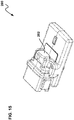
- FIG. 15 depicts another controller 200 (e.g., a control module) in accordance with the principles of the present disclosure.
- the controller 200 has the same construction as the controllers 40, 10 except the solenoid connector 42 and the plug 20 have been eliminated and this region is closed with overmolded material of the housing to form a closed, blank location 202.
- all electrical connections with solenoids, sensors, power, bus connections and other connections can be made through the connector 16 via an electrical wire harness.
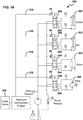
- FIG. 16 shows a hydraulic system 300 incorporating modular controllers 40 in accordance with the principles of the present disclosure.
- the hydraulic system 300 includes hydraulic actuators 302 (e.g., hydraulic cylinders, hydraulic motors, etc.) distributed throughout the system.
- the hydraulic actuators 302 are controlled by valves 304 which are controlled by solenoids 306.
- the controllers 40 are each assigned to a given one of the solenoids 306 and thus are distributed throughout the system to provide a distributed control system.
- the controllers 40 are shown mounted to each solenoid 306, but could also be mounted to the valve blocks or elsewhere in relative close proximity to their assigned solenoid.
- a communication protocol (e.g., Ethernet, CAN bus) can be used as part of a network (e.g., with wired and optionally wireless communication capabilities) to coordinate operation of the controllers 40 through a central control 308.
- Wiring can be used to provide power to the controllers 40 and solenoids and to allow for communication between the various electronic components of the system.
- the wiring can include wiring harnesses 310 that branch from a central cable or cables.
- the hydraulic system 300 can be integrated as part of an off-road vehicle such as a piece of construction or agricultural equipment for controlling operation of active components of the vehicle.
- Example pieces of equipment can include cranes, backhoes loaders, excavators, tractors, telehandlers, concrete pump trucks, etc.
Landscapes
- Engineering & Computer Science (AREA)
- Microelectronics & Electronic Packaging (AREA)
- Connector Housings Or Holding Contact Members (AREA)
- Details Of Connecting Devices For Male And Female Coupling (AREA)
Abstract
Description
- Hydraulic equipment and corresponding systems often rely on electromagnetic actuators such as solenoids to control the operating states of hydraulic valves used to control the operation of hydraulic actuators such as hydraulic cylinders or hydraulic motors. Control modules are used to control the electromagnetic actuators. Such control modules include delicate electronics susceptible to external stresses and contamination from the external environment.
- In general terms, the present disclosure is directed to an improved control module for hydraulic equipment and other applications, as well as a method of manufacturing such a control module. The control module includes a housing that houses a plurality of electronic components.
- The principles of the present disclosure are not limited to a particular type of control module or to a particular use application for such a control module. Control modules of various types are used across many industries to control mechanical, electrical, electronic, hydraulic (e.g., a crane, a backhoe or other loader, an excavator, a tractor, a telehandler, etc.), pneumatic and other devices and systems. It should be appreciated that the present disclosure encompasses all such applications and types of control modules. In addition, the present disclosure encompasses any device that includes a housing that houses one or more electronic components where it is desirable to protect the electronics from stresses and contamination originating outside of the housing.
- One benefit of the control module of the present disclosure is improved sealing by the housing of the electronics internal to the housing against water ingress and related failures.
- Another benefit of the control module is reduced stress on the internal electronics from external forces.
- Another benefit of the control module is a transparent or translucent window built in to the housing that allows visualization of indicator lights from at least one, at least two, or at least three different sides of the housing.
- According to certain aspects of the present disclosure, a control module comprises a connector, and a housing defining a first opening that receives the connector, and a hermetically sealed interior housing at least one electronic component, the electronic component being electrically coupled to the connector, the control module further including a retaining clip in physical contact with the housing and mechanically coupling the at least one electronic component to the connector.
- In some examples, the at least one electronic component is a printed circuit board (PCB). In some examples, pins of the connector are connected to the circuit board via conductors that are soldered to the circuit board. In some examples, the clip substantially defines a U-shape or squared U-shape. In some examples, the clip includes first and second pairs of through holes, the first pair of through holes being adapted to receive fasteners (e.g., screws) to secure the clip to the electronic component, and the second pair of through holes being adapted to receive fasteners (e.g., screws) to secure the control module to a support structure. In some examples, the clip includes a crossbar and two members extending substantially parallel to each other and substantially perpendicularly to the crossbar from opposite ends of the crossbar, the cross bar and two members substantially defining the U-shape or squared U-shape. In some examples, the two members define both the first and second pairs of through holes. In some examples, the members cooperate with shoulders of the connector to couple the connector to the at least one electronic component. In some examples, the crossbar defines a recess and one or more prongs adapted to secure a plug or a second connector. In some examples, the housing includes a transparent or translucent window through which light from one or more indicator light sources (e.g., light emitting diodes) of the at least one electronic component are visible externally to the housing. In some examples, the window extends continuously on at least two or at least three different sides of the housing. In some examples, two of the at least two or at least three different sides are at least substantially perpendicular or at least substantially parallel to each another. In some examples, the housing includes a first transparent inner layer and an opaque outer layer abutting the inner layer. In some examples, the housing is made from one or more flexible materials. In some examples, the inner housing layer is made from a transparent rigid material and the outer housing layer is made from an opaque flexible material.
- According to further aspects of the present disclosure, a method of manufacturing a control module comprises: coupling a connector to a printed circuit board (PCB) with a clip; electrically connecting pins of the connector to the PCB; over-molding the PCB, the clip, and a portion of the connector with a first material to provide a housing that hermetically seals the PCB within the housing; and, optionally over-molding the first material with a second material, the second material forming an outer layer of the housing.
- In some examples, the first material is transparent or translucent, the second material is opaque, and over-molding the second material is such that there is a void in the outer layer of the housing, the void corresponding to a window allowing visualization exterior to the housing of light from one or more light sources positioned on the PCB. In some examples, the void extends continuously on at least two or at least three sides of the housing. In some examples, the first material and the second material, or at least the second material, are flexible and adapted to provide a hermetic seal around the PCB. In some examples, the clip mechanically cooperates with shoulders of the connector, and the clip defines a plurality of openings through which fasteners (e.g., screws) are inserted to fasten the clip to the PCB and/or to fasten the control module to a support structure.
-
-
FIG. 1 is a perspective view of first embodiment of an assembled control module in accordance with the present disclosure. -
FIG. 2 is a perspective view of a second embodiment of an assembled control module in accordance with the present disclosure. -
FIG. 3 is a perspective view of the assembled control module ofFIG. 2 , schematically illustrating mating surfaces for a molding procedure used to assemble the control module. -
FIG. 4 is a perspective view of the assembled control module ofFIG. 1 , schematically illustrating mating surfaces for a molding procedure used to assemble the control module. -
FIG. 5 is a side perspective view of the assembled control module ofFIG. 2 , the control module being connected to a solenoid. -
FIG. 6 is a bottom view of the assembled control module and solenoid ofFIG. 5 . -
FIG. 7 is a top view of the assembled control module ofFIG. 1 . -
FIG. 8 is a perspective view of a partially assembled control module of the present disclosure. -
FIG. 9 is a further perspective view of the partially assembled control module ofFIG. 8 . -
FIG. 10 is a side view of the control module ofFIG. 2 including transparencies to aid in description. -
FIG. 11 is a back view of the control module ofFIG. 1 . -
FIG. 12 is a perspective of a retaining clip used in control modules in accordance with the principles of the present disclosure for structurally securing connectors of the modules to circuit boards of the modules. -
FIG. 13 is another perspective view of the retaining clip ofFIG. 12 . -
FIG. 14 is a side elevational view of the control module ofFIG. 2 connected with a solenoid; -
FIG. 15 depicts another control module in accordance with the principles of the present disclosure. -
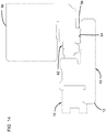
FIG. 16 depicts a distributed control system for a hydraulic system suitable for using control modules in accordance with the principles of the present disclosure. - Various embodiments will be described in detail with reference to the figures, where like reference numbers correspond to like features across the several views. Reference to various embodiments does not limit the scope of the claims attached hereto. Additionally, any examples set forth in this specification are not intended to be limiting and merely set forth some of the many possible embodiments for the appended claims.
- Referring to
FIG. 1 , acontroller 10 adapted to provide signals to control hydraulic fluid pressure and/or flow rate at one or more hydraulic drivers (e.g., cylinders) in hydraulic equipment includes ahousing 12 defining afirst opening 14 for receiving aconnector 16 and asecond opening 18 for receiving aplug 20. Theconnector 16 and theplug 20 are overmolded and fixed within theircorresponding openings controller 10 has atop 11, abottom 13, afront 15, and aback 17. Theconnector 16 includes a plurality of conductors (e.g.,pins 120, seeFIGS. 10 and11 ) adapted to electrically couple to a conductive harness received in theconnector 16 from theback 17, the conductive harness acting as a data bus between thecontroller 10 and other electronics, such as memory, processors, input/output interfaces, etc. Thepins 120 of theconnector 16 are electrically connected to a PCB 121 (seeFIGS. 8-10 ) housed inside thehousing 12. In addition, electrical contacts disposed in or near thesecond opening 18 are also electrically connected with the PCB 121 housed inside thehousing 12. - The
connector 16 is depicted as a female connector including asocket 123 for receiving a plug of an electrical harness. Thesocket 123 is defined by aconnector housing 125. Theelectrical pins 120 are positioned within thesocket 123 and can be arranged in one or more rows (seeFIG. 11 ). While the number ofpins 120 can be varied, in certain examples, theconnector 16 includes twelve of thepins 120 arranged in two rows of six pins each. In one example, thepins 120 each have a right angled configuration with upper andlower extensions FIG. 10 ). Eachupper extension 120a is positioned within thesocket 123 and extends parallel to thePCB 121 in a rearward direction from itscorresponding bend 127. Eachlower extension 120b is perpendicular to thePCB 121 and extends downwardly from itscorresponding bend 127. Thelower extensions 120b can be staked within vias defined by thePCB 121. The vias can electrically connect thepins 120 to conductive traces on thePCB 121. - The
PCB 121 can include devices including memory and one or more electronic processors adapted to execute computer readable instructions stored in memory. The processors can be adapted to control operation of solenoids or other electronic actuators for controlling hydraulic valves or other hydraulic devices. ThePCB 121 can also include sensing devices such as magnetometers, accelerometers and gyroscopes. In one example, the magnetometers, accelerometers and the gyroscopes can be three axis devices. ThePCB 121 can also include power conversion circuitry. Theextensions 120a of thepins 120 can provide sensor input locations, sensor output locations, power connection locations, solenoid connection locations, or other connection locations for interfacing with thePCB 121. - The
housing 12 includes a transparent inner layer 22 (see cut-away atFIG. 4 ) and an opaque over-molded flexible outer layer 24 (see cut-away atFIG. 4 ) disposed on theinner layer 22. A void 26 in theouter layer 24 is formed during the molding process, providing awindow 28. Light emitted by one or morelight sources 30 positioned on thePCB 121 housed inside thehousing 12 is visible through thewindow 28. Alternatively, a portion of theouter layer 24 is cut out after theouter layer 24 is formed, to provide thewindow 28. Referring toFIGS. 5-7 , thewindow 28 in thecontrollers window 28 including from the top 11, from the bottom 13, and from theside 19. Thewindow 28 thus has parallel portions on a top surface and bottom surface of thehousing 12 and a perpendicular portion on the side adjoining the top and bottom portions. The control module can include light guides for guiding light (e.g., via total internal reflection or other means) from a light source (e.g., a light emitting diode) on thePCB 121 to thewindow 28. - Referring the
FIG. 2 , thecontroller 40 ofFIG. 2 is identical to thecontroller 10 ofFIG. 1 , except that instead of theplug 20, thecontroller 40 includes asolenoid connector 42. Thesolenoid connector 42 is a 2-contact (e.g., 2-pin) connector received (e.g., overmolded) in theopening 18 of thehousing 12 and is electrically connected to thePCB 121 housed by thehousing 12. Thesolenoid connector 42 includescontacts 43a, 43b which are preferably electrically connected to thecircuit board 121 by electrical wires routed through thehousing 12 from thecontacts 43a, 43b to thecircuit board 121. Thesolenoid connector 42 is adapted to connect to a solenoid, e.g., a solenoid that drives a spool of a spool valve or a poppet of a poppet valve to regulate flow to a hydraulic cylinder or other actuator. Thecontroller 40 controls the solenoid by providing control signals via theconnector 42. Referring toFIGS. 5 and6 , the 2-contact solenoid connector 42 of thecontroller 40 is shown connected to asolenoid 56. -
FIGS. 3-4 illustrate a cost saving feature of manufacturing thecontrollers lines housing 12. The mating surfaces 50 and 52 are the same whether the finished controller includes theplug 20 or theconnector 42. Thus, the same molds can be used to manufacture bothcontroller embodiments - Referring to
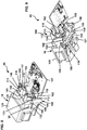
FIGS. 8-9 , a partially assembled controller is shown. The partially assembled controller can be assembled into either thecontroller 10 or thecontroller 40 described above. In certain implementations, thepartial assembly 80 includes theharness connector 16, thePCB 121 having circuity and LED indicator lights, aretainer clip 100, and theplug 20 or the connector 42 (not shown atFIGS. 8 and 9 ). - The
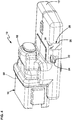
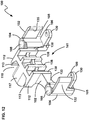
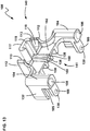
retainer clip 100 substantially defines a squared U-shape. In particular, theretainer clip 100 includes acrossbar 102 and twoside members 104 extending substantially parallel to each other and substantially perpendicularly to thecrossbar 102 from opposite ends of the crossbar, thecrossbar 102 and twoside members 104 substantially defining the squared U-shape. Theretainer clip 100 has afront side 140 adapted to face toward thefront 15 of thecontroller 10 and aback side 141 adapted to face toward theback 17 of thecontroller 10. Theclip 100 is preferably a unitary molded plastic piece. - The
retainer clip 100 includes first and second pairs of through holes, 106, 108, the first pair of throughholes 106 being adapted to receive fasteners (e.g., screws) to secure theclip 100 to thePCB 121, and the second pair of throughholes 108 being adapted to receive fasteners (e.g., screws) to secure thecontrol module FIG. 10 ) of a portion of a piece of machinery into which the controller is integrated. Thesupport surface 90 can also be a valve block or manifold including valves controlled by thecontroller holes 108 extend lengthwise in a vertical orientation through theside members 104. When thehousing 12 is overmolded over theretainer clip 100, one or more inserts can be used to ensure the housing defines fastener openings 109 (FIGS. 6 and 7 ) that co-axially align with the throughholes 108 so that fasteners can be inserted vertically through the overmolded walls of thehousing 12 as well as through the throughholes 108 to secure thecontroller support surface 90. - The
retainer clip 100 includesboard engagement tabs 130 and connector latching fingers 132 (e.g., retaining fingers) that project rearwardly from theback side 141 of theclip 100. Theboard engagement tabs 130 and theconnector latching fingers 132 have base ends that are unitary with theside members 104. Theboard engagement tabs 130 are located adjacent lower ends of theside members 104 and theconnector latching fingers 132 are positioned at mid locations along the lengths of theside members 104 above theboard engagement tabs 130. Theboard engagement tabs 130 have major sides that are aligned along a horizontal plane and theconnector latching fingers 132 have major sides aligned along vertical planes.Board receiving notches 105 are defined vertically between theboard engagement tabs 130 and theconnector latching fingers 132. The throughholes 106 are defined through the major sides of theboard engagement tabs 130 and preferably extend through theboard engagement tabs 130 in a vertical orientation. Aconnector receiving pocket 133 is defined between theconnector latching fingers 132 at theback side 141 of theclip 100. Thepocket 133 is adapted to receive theconnector housing 125 of theconnector 16 therein. Theclip 100 also includes a plurality ofvertical rails 138 at theback side 141 within thepocket 133 which function as standoffs against which theconnector housing 125 abuts when theconnector 16 is mounted in thepocket 133 and retained in thepocket 133 by the latchingfingers 132. Laterally inwardly projecting latchingcatches 135 are provided adjacent rear ends of the latchingfingers 132 for assisting in retaining theconnector 16 in thepocket 133. - When the
connector housing 125 is inserted rearwardly into thepocket 133, the latchingfingers 132 engage oppositelateral shoulders 25 of theconnector housing 125 causing the latchingfingers 132 to flex laterally outwardly to accommodate the connector housing. The latchingfingers 132 resiliently snap back laterally inwardly to retain theconnector housing 125 in thepocket 133 by a snap-fit connection once theshoulders 25 move past thecatches 135 and theconnector housing 125 abuts against therails 138. With theconnector housing 125 is fully inserted into thepocket 133, thehousing 125 is secured between thecatches 135 and therails 138. - The
clip 100 also includes another connector pocket 110 (e.g., a recess) at thefront side 140 of theclip 100 for mounting thesolenoid connector 42 or theplug 20 to theclip 100. Theconnector pocket 110 is defined by latching fingers 112 (e.g., prongs) that extend forwardly from thecross bar 102. The latchingfingers 112 have base ends integrally formed with the cross-bar and includecatches 113 adjacent free ends of the latchingfingers 112. Thecatches 113 project laterally inwardly from the free ends and are adapted for engaging flanges 115 (seeFIG. 10 ) on thesolenoid connector 42 or theplug 20 when such structures are mounted in theconnector pocket 110 to retain such structures in thepocket 110 by a snap-fit connection. Theclip 100 also includes aninsert portion 117 that projects forwardly from thecross bar 102 into thepocket 110 at a location between the latchingfingers 112. Theinsert portion 117 is adapted to fit within an opening of thesolenoid connector 42 or plug 20 and preferable has a shape that complements the opening. Theinsert portion 117 definescentral wire passage 119 for routing wires or other conductors from theconnector 42 through theinsert portion 117 and into the interior of thehousing 12. The front side of theclip 100 can includevertical channels 160 for routing the electrical wires from theinsert portion 117 through thehousing 12 to thePCB 121. The wires preferably are electrically connected to conductive traces on thePCB 121. - As shown at
FIGS. 8 and 9 , thePCB 121 includesside notches 162 for receiving lower ends of theside members 104 of theclip 100. During the assembly process, the lower ends of theconductors 120 of theconnector 16 can be coupled to thePCB 121 such that the connector is at the top side of thePCB 121. The retainingclip 100 can then be positioned with the lower ends of theside members 104 in theside notches 162. As so positioned, the retainingclip 100 can be slid forwardly relative to thePCB 121 and theconnector 16 such that theconnector 16 snaps into thepocket 133 and thePCB 121 fits into thenotch 105 with theboard engagement tabs 130 positioned beneath thePCB 121. Fasteners such as screws can then be installed through theopenings 106 in theboard engagement tabs 130 to secure theclip 100 and theconnector 16 to thePCB 121. For example, the fasteners such as screws can be driven upwardly through theopenings 106 and through thePCB 121 into theshoulders 25 of theconnector 16 to lock theclip 100 and theconnector 16 in place relative to thePCB 121. - The
solenoid connector 42 or theplug 20 can then be installed at thepocket 110 to secure theconnector 42 or plug 20 to theclip 100, and any wire routing and electrical connections with thePCB 121 corresponding to theplug 20 or theconnector 42 are completed. After the mechanical connections are made to the 2 and 12pin connectors inner layer 22 can be overmolded over the assembly to form thehousing 12 such thatPCB 121, theclip 100, and portions of theconnector 16 and theconnector 42 or plug 20 are encased within theinner layer 22. Theinner layer 22 can provide sealing and mechanical protection with respect to the inner parts. In certain examples, the inner layer can adhere to the circuit board and portions of theconnector 16, theconnector 42 or theplug 20. In certain examples, portions of theconnector 16, theconnector 42 or the plug can be overmolded and embedded within theinner layer 22 to provide mechanical couplings between theinner layer 22 and theparts parts PCB 121. - In a preferred example, the
outer layer 24 is overmolded over theinner layer 22 in a subsequent overmolding process. In certain examples, the inner andouter layers inner layer 22 is transparent and theouter layer 22 is opaque. In other embodiments, the overmolding may optionally include only one overmolded layer. Thus, theouter layer 24 can be eliminated. -
FIGS. 8 and 9 show theclip 100 and theconnector 16 assembled on thePCB 121. As assembled, theboard engagement tabs 130 are aligned (in the top to bottom direction) with theshoulders 25 of theconnector 16 to couple theconnector 16 to thePCB 121 by inserting fasteners into through holes in theshoulders 25, the aligned throughholes 106 in theclip 100, and through thePCB 121. In addition, the retainingclip 100 can be made from a rigid but resilient material, and appropriately dimensioned relative to theshoulder 25 to allow theretaining clip 100 to be snapped about theshoulders 25 and thereby provide frictional coupling between the retainingclip 100 and theconnector 16 even before fasteners are inserted in the through-holes 106. In at least some examples, the retainingclip 100 is made from a substantially rigid material that is more rigid than the materials used for the inner orouter layers housing 12. Thus, the retainingclip 100 is a frame that provides structural reinforcement to thecontroller 40. - Once the
housing 12 is formed, the through holes 108 (seeFIGS. 5-7 ) remain exposed on the top 11 and bottom 13 of thecontroller controller surface 90 inFIG. 10 ), using theretaining clip 100, which is then entirely or almost entirely housed by thehousing 12. - Referring to
FIG. 10 , thecontroller 40 is shown fastened to aflat surface 90 of a support structure using fasteners inserted through the throughholes 108 that are open at the top and bottom of thehousing 12. Because thePCB 121 is coupled directly only to the retainingclip 100 and theconnector 16, and this coupling is essentially along or approximately along a single reference plane or axis A, pivotal movement of theconnector 42 in the direction of either of thearrows 150 imparts little to no stress on thePCB 121. Reducing stress on thePCB 121 in this way and similar ways using the controller assemblies of the present disclosure provides a more durable controller that is less susceptible to damage. For example, when thecontroller 40 is attached to thesurface 90 by fasteners extending through theopenings 108, loading/torque applied to theconnector 16 or theconnector 42 is transferred through theclip 100 to thesurface 90 thereby bypassing thePCB 121 and preventing or reducing flexing of thePCB 121. When thecontroller 40 is attached to a solenoid, side loading applied to theconnector 16 can be transferred to the solenoid through theclip 100, thereby bypassing thePCB 121. - Referring to
FIG. 14 , thesolenoid connector 42 mates with aconnector 58 of thesolenoid 56. Themating connector 58 has a body that extends at least partially around a periphery of thesolenoid connector 42. In certain implementations, thehousing 12 includes asupport member 54 that contacts the body of themating connector 58 when themating connector 58 is fitted with thesolenoid connector 42. The body of themating connector 58 seats on thesupport member 54 to inhibit strain from being applied to themating connector 58 at the point of connection between thesolenoid connector 42 and themating connector 58. -
FIG. 15 depicts another controller 200 (e.g., a control module) in accordance with the principles of the present disclosure. Thecontroller 200 has the same construction as thecontrollers solenoid connector 42 and theplug 20 have been eliminated and this region is closed with overmolded material of the housing to form a closed,blank location 202. In this example, all electrical connections with solenoids, sensors, power, bus connections and other connections can be made through theconnector 16 via an electrical wire harness. -
FIG. 16 shows ahydraulic system 300 incorporatingmodular controllers 40 in accordance with the principles of the present disclosure. Thehydraulic system 300 includes hydraulic actuators 302 (e.g., hydraulic cylinders, hydraulic motors, etc.) distributed throughout the system. Thehydraulic actuators 302 are controlled byvalves 304 which are controlled bysolenoids 306. Thecontrollers 40 are each assigned to a given one of thesolenoids 306 and thus are distributed throughout the system to provide a distributed control system. Thecontrollers 40 are shown mounted to eachsolenoid 306, but could also be mounted to the valve blocks or elsewhere in relative close proximity to their assigned solenoid. A communication protocol (e.g., Ethernet, CAN bus) can be used as part of a network (e.g., with wired and optionally wireless communication capabilities) to coordinate operation of thecontrollers 40 through acentral control 308. Wiring can be used to provide power to thecontrollers 40 and solenoids and to allow for communication between the various electronic components of the system. The wiring can include wiring harnesses 310 that branch from a central cable or cables. In certain examples, thehydraulic system 300 can be integrated as part of an off-road vehicle such as a piece of construction or agricultural equipment for controlling operation of active components of the vehicle. Example pieces of equipment can include cranes, backhoes loaders, excavators, tractors, telehandlers, concrete pump trucks, etc. - The various embodiments described above are provided by way of illustration only and should not be construed to limit the claims attached hereto. Those skilled in the art will readily recognize various modifications and changes that may be made without following the example embodiments and applications illustrated and described herein, and without departing from the true spirit and scope of the following claims.
Claims (15)
- A control module comprising:a connector; anda housing defining a first opening that receives the connector, and a hermetically sealed interior housing at least one electronic component, the electronic component being electrically coupled to the connector, the control module further including a retaining clip in physical contact with the housing and mechanically coupling the at least one electronic component to the connector.
- The control module of claim 1, wherein the at least one electronic component comprises a printed circuit board (PCB).
- The control module of claim 1, wherein the clip substantially defines a U-shape or squared U-shape.
- The control module of claim 1, wherein the clip includes first and second pairs of through holes, the first pair of through holes being adapted to receive fasteners to secure the clip to the electronic component, and the second pair of through holes being adapted to receive fasteners to secure the control module to a support structure.
- The control module of claim 1, wherein the clip includes a crossbar and two members extending substantially parallel to each other and substantially perpendicularly to the crossbar from opposite ends of the crossbar, the crossbar and two members substantially defining a squared U-shape.
- The control module of claim 5, wherein the two members define the first opening through their lengths, and wherein the second openings are defined by circuit board engagement tabs that project from the members.
- The control module of claim 5, wherein the members snap-fit with shoulders of the connector to couple the connector to the at least one electronic component.
- The control module of claim 5, wherein the crossbar defines a recess and one or more prongs adapted to secure a plug or a second connector.
- The control module of claim 1, wherein the housing includes a transparent window through which light from one or more indicator light sources positioned on the at least one electronic component are visible externally to the housing.
- The control module of claim 9, wherein the window extends continuously on at least two or at least three different sides of the housing.
- The control module of claim 10, wherein two of the at least two or at least three different sides are at least substantially perpendicular or at least substantially parallel to each another.
- The control module of claim 1, wherein the housing includes a first transparent inner layer and a second opaque outer layer abutting the inner layer.
- The control module of claim 1, wherein the housing is made from one or more flexible and waterproof materials.
- A method of manufacturing the control module of claim 1, wherein the electronic component is a printed circuit board (PCB), the method comprising:coupling the connector to the printed circuit board (PCB) with the clip;electrically connecting pins of the connector to the PCB;over-molding the PCB, the clip and a portion of the connector with a first material to provide a housing that hermetically seals the PCB within the housing; and,optionally over-molding the first material with a second material, the second material forming an outer layer of the housing.
- The method of claim 14, wherein the first material is transparent, the second material is opaque, and the over-molding the second material is not optional and is such that there is a void in the outer layer of the housing, the void corresponding to a window allowing visualization exterior to the housing of light from one or more light sources positioned on the PCB, and wherein the void optionally extends continuously on at least two or at least three sides of the housing.
Applications Claiming Priority (2)
| Application Number | Priority Date | Filing Date | Title |
|---|---|---|---|
| US201862692072P | 2018-06-29 | 2018-06-29 | |
| US16/453,261 US11272630B2 (en) | 2018-06-29 | 2019-06-26 | Hydraulic system control module having improved housing features and method of manufacturing the same |
Publications (2)
| Publication Number | Publication Date |
|---|---|
| EP3589095A1 true EP3589095A1 (en) | 2020-01-01 |
| EP3589095B1 EP3589095B1 (en) | 2021-01-13 |
Family
ID=67139648
Family Applications (1)
| Application Number | Title | Priority Date | Filing Date |
|---|---|---|---|
| EP19183743.4A Active EP3589095B1 (en) | 2018-06-29 | 2019-07-01 | Hydraulic system control module having improved housing features and method of manufacturing the same |
Country Status (2)
| Country | Link |
|---|---|
| US (1) | US11272630B2 (en) |
| EP (1) | EP3589095B1 (en) |
Families Citing this family (2)
| Publication number | Priority date | Publication date | Assignee | Title |
|---|---|---|---|---|
| US11220229B2 (en) * | 2019-02-15 | 2022-01-11 | Reid Lunde | Modular power distribution device |
| US11277927B2 (en) * | 2019-11-05 | 2022-03-15 | Lear Corporation | System and method for mounting an electronics arrangement |
Citations (6)
| Publication number | Priority date | Publication date | Assignee | Title |
|---|---|---|---|---|
| US5236098A (en) * | 1992-03-13 | 1993-08-17 | Thomas & Betts Corporation | Socket and header electrical connector assembly |
| US20060023426A1 (en) * | 2004-07-29 | 2006-02-02 | Aisin Aw Co., Ltd. | Automatic transmission electronic control device |
| US20140285987A1 (en) * | 2013-03-21 | 2014-09-25 | Hitachi Automotive Systems, Ltd. | Electronic control device |
| US9136621B1 (en) * | 2012-08-14 | 2015-09-15 | Ciena Corporation | Guides and tab arrangement to retain a card having an edge connector and method of use |
| US20170162959A1 (en) * | 2015-12-07 | 2017-06-08 | Valeo Vision | Connection module for motor vehicle |
| US20180131109A1 (en) * | 2016-05-16 | 2018-05-10 | Boe Technology Group Co., Ltd. | Ac power socket |
Family Cites Families (8)
| Publication number | Priority date | Publication date | Assignee | Title |
|---|---|---|---|---|
| US20080064265A1 (en) * | 2006-09-12 | 2008-03-13 | Safenet, Inc. | Housing for portable computer device and method of making same |
| US7850476B2 (en) * | 2008-10-29 | 2010-12-14 | Tyco Electronics Corporation | Low profile solar laminate connector assembly |
| US8708740B2 (en) * | 2011-11-22 | 2014-04-29 | Henry Liou | Waterproof radio accessory connector assembly |
| US8894445B2 (en) * | 2012-02-09 | 2014-11-25 | Apple Inc. | Connector receptacle with side ground contacts |
| US9160118B2 (en) * | 2012-05-21 | 2015-10-13 | Idea Boxx, Llc | Lighted electrical interconnect assembly |
| KR102158577B1 (en) * | 2014-10-08 | 2020-09-22 | 엘지이노텍 주식회사 | Radar device for vehicle |
| US9865951B2 (en) * | 2016-05-06 | 2018-01-09 | Alltop Electronics (Suzhou) Ltd. | Connector for flexible printed circuit board |
| TW201813147A (en) * | 2016-07-15 | 2018-04-01 | 半導體能源研究所股份有限公司 | Display device, display module, electronic device, and manufacturing method of display device |
-
2019
- 2019-06-26 US US16/453,261 patent/US11272630B2/en active Active
- 2019-07-01 EP EP19183743.4A patent/EP3589095B1/en active Active
Patent Citations (6)
| Publication number | Priority date | Publication date | Assignee | Title |
|---|---|---|---|---|
| US5236098A (en) * | 1992-03-13 | 1993-08-17 | Thomas & Betts Corporation | Socket and header electrical connector assembly |
| US20060023426A1 (en) * | 2004-07-29 | 2006-02-02 | Aisin Aw Co., Ltd. | Automatic transmission electronic control device |
| US9136621B1 (en) * | 2012-08-14 | 2015-09-15 | Ciena Corporation | Guides and tab arrangement to retain a card having an edge connector and method of use |
| US20140285987A1 (en) * | 2013-03-21 | 2014-09-25 | Hitachi Automotive Systems, Ltd. | Electronic control device |
| US20170162959A1 (en) * | 2015-12-07 | 2017-06-08 | Valeo Vision | Connection module for motor vehicle |
| US20180131109A1 (en) * | 2016-05-16 | 2018-05-10 | Boe Technology Group Co., Ltd. | Ac power socket |
Also Published As
| Publication number | Publication date |
|---|---|
| EP3589095B1 (en) | 2021-01-13 |
| US11272630B2 (en) | 2022-03-08 |
| US20200008312A1 (en) | 2020-01-02 |
Similar Documents
| Publication | Publication Date | Title |
|---|---|---|
| CN110562229B (en) | Electromechanical brake connector | |
| US6592266B1 (en) | Fiber optic cable connector clip | |
| US7445490B2 (en) | Integrated overmolded cable seal and gasket for an electronic module | |
| US11272630B2 (en) | Hydraulic system control module having improved housing features and method of manufacturing the same | |
| US7950942B2 (en) | Secured plug connection and method for its production | |
| EP2755870B1 (en) | Vehicle diagnostic system | |
| US7073410B2 (en) | Hydraulic motor vehicle gearbox control device with a plastic hydraulic distribution plate and conductors integrated therein | |
| US10457345B2 (en) | Method for manufacturing an automotive mirror | |
| US20100099279A1 (en) | Waterproof Connector, Mounting Structure of Waterproof Connector and Mounting Method of Waterproof Connector | |
| US11765843B2 (en) | Housing for an electronic control unit and method of manufacture | |
| KR20090077041A (en) | Wiring system | |
| CN111801503B (en) | Electronic hydraulic unit | |
| KR102859178B1 (en) | Manifold solenoid valve and valve base | |
| CN103797654A (en) | Connectors, especially electrical connectors | |
| CN101513145A (en) | Transport box for electronic flat modules | |
| EP0484289B1 (en) | A connector for an electronic control unit | |
| EP1345798B1 (en) | Rear wiper hatch cassette using interlocking parts | |
| CN222980888U (en) | Connectors and Automobiles | |
| WO2009090470A2 (en) | Sealed connector | |
| KR100765679B1 (en) | Structure for attaching oil-enclosed equipment and control unit | |
| EP1241738B1 (en) | Electrical connector, particularly for vehicles | |
| US6991476B2 (en) | Electrical component of a motor vehicle | |
| KR20040034461A (en) | Air vent | |
| JP7330121B2 (en) | Manifold solenoid valve and valve base | |
| US20250350079A1 (en) | Connector adapter |
Legal Events
| Date | Code | Title | Description |
|---|---|---|---|
| PUAI | Public reference made under article 153(3) epc to a published international application that has entered the european phase |
Free format text: ORIGINAL CODE: 0009012 |
|
| STAA | Information on the status of an ep patent application or granted ep patent |
Free format text: STATUS: REQUEST FOR EXAMINATION WAS MADE |
|
| 17P | Request for examination filed |
Effective date: 20190701 |
|
| AK | Designated contracting states |
Kind code of ref document: A1 Designated state(s): AL AT BE BG CH CY CZ DE DK EE ES FI FR GB GR HR HU IE IS IT LI LT LU LV MC MK MT NL NO PL PT RO RS SE SI SK SM TR |
|
| AX | Request for extension of the european patent |
Extension state: BA ME |
|
| GRAP | Despatch of communication of intention to grant a patent |
Free format text: ORIGINAL CODE: EPIDOSNIGR1 |
|
| STAA | Information on the status of an ep patent application or granted ep patent |
Free format text: STATUS: GRANT OF PATENT IS INTENDED |
|
| INTG | Intention to grant announced |
Effective date: 20200819 |
|
| GRAS | Grant fee paid |
Free format text: ORIGINAL CODE: EPIDOSNIGR3 |
|
| GRAA | (expected) grant |
Free format text: ORIGINAL CODE: 0009210 |
|
| STAA | Information on the status of an ep patent application or granted ep patent |
Free format text: STATUS: THE PATENT HAS BEEN GRANTED |
|
| AK | Designated contracting states |
Kind code of ref document: B1 Designated state(s): AL AT BE BG CH CY CZ DE DK EE ES FI FR GB GR HR HU IE IS IT LI LT LU LV MC MK MT NL NO PL PT RO RS SE SI SK SM TR |
|
| REG | Reference to a national code |
Ref country code: GB Ref legal event code: FG4D |
|
| REG | Reference to a national code |
Ref country code: CH Ref legal event code: EP |
|
| REG | Reference to a national code |
Ref country code: IE Ref legal event code: FG4D |
|
| REG | Reference to a national code |
Ref country code: DE Ref legal event code: R096 Ref document number: 602019002160 Country of ref document: DE |
|
| REG | Reference to a national code |
Ref country code: AT Ref legal event code: REF Ref document number: 1355515 Country of ref document: AT Kind code of ref document: T Effective date: 20210215 |
|
| REG | Reference to a national code |
Ref country code: AT Ref legal event code: MK05 Ref document number: 1355515 Country of ref document: AT Kind code of ref document: T Effective date: 20210113 |
|
| REG | Reference to a national code |
Ref country code: NL Ref legal event code: MP Effective date: 20210113 |
|
| REG | Reference to a national code |
Ref country code: LT Ref legal event code: MG9D |
|
| PG25 | Lapsed in a contracting state [announced via postgrant information from national office to epo] |
Ref country code: LT Free format text: LAPSE BECAUSE OF FAILURE TO SUBMIT A TRANSLATION OF THE DESCRIPTION OR TO PAY THE FEE WITHIN THE PRESCRIBED TIME-LIMIT Effective date: 20210113 Ref country code: NO Free format text: LAPSE BECAUSE OF FAILURE TO SUBMIT A TRANSLATION OF THE DESCRIPTION OR TO PAY THE FEE WITHIN THE PRESCRIBED TIME-LIMIT Effective date: 20210413 Ref country code: PT Free format text: LAPSE BECAUSE OF FAILURE TO SUBMIT A TRANSLATION OF THE DESCRIPTION OR TO PAY THE FEE WITHIN THE PRESCRIBED TIME-LIMIT Effective date: 20210513 Ref country code: BG Free format text: LAPSE BECAUSE OF FAILURE TO SUBMIT A TRANSLATION OF THE DESCRIPTION OR TO PAY THE FEE WITHIN THE PRESCRIBED TIME-LIMIT Effective date: 20210413 Ref country code: HR Free format text: LAPSE BECAUSE OF FAILURE TO SUBMIT A TRANSLATION OF THE DESCRIPTION OR TO PAY THE FEE WITHIN THE PRESCRIBED TIME-LIMIT Effective date: 20210113 Ref country code: GR Free format text: LAPSE BECAUSE OF FAILURE TO SUBMIT A TRANSLATION OF THE DESCRIPTION OR TO PAY THE FEE WITHIN THE PRESCRIBED TIME-LIMIT Effective date: 20210414 Ref country code: FI Free format text: LAPSE BECAUSE OF FAILURE TO SUBMIT A TRANSLATION OF THE DESCRIPTION OR TO PAY THE FEE WITHIN THE PRESCRIBED TIME-LIMIT Effective date: 20210113 |
|
| PG25 | Lapsed in a contracting state [announced via postgrant information from national office to epo] |
Ref country code: RS Free format text: LAPSE BECAUSE OF FAILURE TO SUBMIT A TRANSLATION OF THE DESCRIPTION OR TO PAY THE FEE WITHIN THE PRESCRIBED TIME-LIMIT Effective date: 20210113 Ref country code: SE Free format text: LAPSE BECAUSE OF FAILURE TO SUBMIT A TRANSLATION OF THE DESCRIPTION OR TO PAY THE FEE WITHIN THE PRESCRIBED TIME-LIMIT Effective date: 20210113 Ref country code: AT Free format text: LAPSE BECAUSE OF FAILURE TO SUBMIT A TRANSLATION OF THE DESCRIPTION OR TO PAY THE FEE WITHIN THE PRESCRIBED TIME-LIMIT Effective date: 20210113 Ref country code: PL Free format text: LAPSE BECAUSE OF FAILURE TO SUBMIT A TRANSLATION OF THE DESCRIPTION OR TO PAY THE FEE WITHIN THE PRESCRIBED TIME-LIMIT Effective date: 20210113 Ref country code: LV Free format text: LAPSE BECAUSE OF FAILURE TO SUBMIT A TRANSLATION OF THE DESCRIPTION OR TO PAY THE FEE WITHIN THE PRESCRIBED TIME-LIMIT Effective date: 20210113 |
|
| PG25 | Lapsed in a contracting state [announced via postgrant information from national office to epo] |
Ref country code: IS Free format text: LAPSE BECAUSE OF FAILURE TO SUBMIT A TRANSLATION OF THE DESCRIPTION OR TO PAY THE FEE WITHIN THE PRESCRIBED TIME-LIMIT Effective date: 20210513 |
|
| REG | Reference to a national code |
Ref country code: DE Ref legal event code: R097 Ref document number: 602019002160 Country of ref document: DE |
|
| PG25 | Lapsed in a contracting state [announced via postgrant information from national office to epo] |
Ref country code: CZ Free format text: LAPSE BECAUSE OF FAILURE TO SUBMIT A TRANSLATION OF THE DESCRIPTION OR TO PAY THE FEE WITHIN THE PRESCRIBED TIME-LIMIT Effective date: 20210113 Ref country code: EE Free format text: LAPSE BECAUSE OF FAILURE TO SUBMIT A TRANSLATION OF THE DESCRIPTION OR TO PAY THE FEE WITHIN THE PRESCRIBED TIME-LIMIT Effective date: 20210113 Ref country code: SM Free format text: LAPSE BECAUSE OF FAILURE TO SUBMIT A TRANSLATION OF THE DESCRIPTION OR TO PAY THE FEE WITHIN THE PRESCRIBED TIME-LIMIT Effective date: 20210113 |
|
| PLBE | No opposition filed within time limit |
Free format text: ORIGINAL CODE: 0009261 |
|
| STAA | Information on the status of an ep patent application or granted ep patent |
Free format text: STATUS: NO OPPOSITION FILED WITHIN TIME LIMIT |
|
| PG25 | Lapsed in a contracting state [announced via postgrant information from national office to epo] |
Ref country code: DK Free format text: LAPSE BECAUSE OF FAILURE TO SUBMIT A TRANSLATION OF THE DESCRIPTION OR TO PAY THE FEE WITHIN THE PRESCRIBED TIME-LIMIT Effective date: 20210113 Ref country code: SK Free format text: LAPSE BECAUSE OF FAILURE TO SUBMIT A TRANSLATION OF THE DESCRIPTION OR TO PAY THE FEE WITHIN THE PRESCRIBED TIME-LIMIT Effective date: 20210113 Ref country code: RO Free format text: LAPSE BECAUSE OF FAILURE TO SUBMIT A TRANSLATION OF THE DESCRIPTION OR TO PAY THE FEE WITHIN THE PRESCRIBED TIME-LIMIT Effective date: 20210113 |
|
| 26N | No opposition filed |
Effective date: 20211014 |
|
| REG | Reference to a national code |
Ref country code: GB Ref legal event code: 732E Free format text: REGISTERED BETWEEN 20211210 AND 20211215 |
|
| REG | Reference to a national code |
Ref country code: DE Ref legal event code: R081 Ref document number: 602019002160 Country of ref document: DE Owner name: DANFOSS A/S, DK Free format text: FORMER OWNER: EATON INTELLIGENT POWER LIMITED, DUBLIN, IE Ref country code: DE Ref legal event code: R081 Ref document number: 602019002160 Country of ref document: DE Owner name: DANFOSS POWER SOLUTIONS II TECHNOLOGY A/S, DK Free format text: FORMER OWNER: EATON INTELLIGENT POWER LIMITED, DUBLIN, IE |
|
| PG25 | Lapsed in a contracting state [announced via postgrant information from national office to epo] |
Ref country code: AL Free format text: LAPSE BECAUSE OF FAILURE TO SUBMIT A TRANSLATION OF THE DESCRIPTION OR TO PAY THE FEE WITHIN THE PRESCRIBED TIME-LIMIT Effective date: 20210113 Ref country code: ES Free format text: LAPSE BECAUSE OF FAILURE TO SUBMIT A TRANSLATION OF THE DESCRIPTION OR TO PAY THE FEE WITHIN THE PRESCRIBED TIME-LIMIT Effective date: 20210113 |
|
| PG25 | Lapsed in a contracting state [announced via postgrant information from national office to epo] |
Ref country code: SI Free format text: LAPSE BECAUSE OF FAILURE TO SUBMIT A TRANSLATION OF THE DESCRIPTION OR TO PAY THE FEE WITHIN THE PRESCRIBED TIME-LIMIT Effective date: 20210113 |
|
| PG25 | Lapsed in a contracting state [announced via postgrant information from national office to epo] |
Ref country code: MC Free format text: LAPSE BECAUSE OF FAILURE TO SUBMIT A TRANSLATION OF THE DESCRIPTION OR TO PAY THE FEE WITHIN THE PRESCRIBED TIME-LIMIT Effective date: 20210113 |
|
| REG | Reference to a national code |
Ref country code: BE Ref legal event code: MM Effective date: 20210731 |
|
| PG25 | Lapsed in a contracting state [announced via postgrant information from national office to epo] |
Ref country code: IT Free format text: LAPSE BECAUSE OF FAILURE TO SUBMIT A TRANSLATION OF THE DESCRIPTION OR TO PAY THE FEE WITHIN THE PRESCRIBED TIME-LIMIT Effective date: 20210113 |
|
| PG25 | Lapsed in a contracting state [announced via postgrant information from national office to epo] |
Ref country code: IS Free format text: LAPSE BECAUSE OF FAILURE TO SUBMIT A TRANSLATION OF THE DESCRIPTION OR TO PAY THE FEE WITHIN THE PRESCRIBED TIME-LIMIT Effective date: 20210513 Ref country code: LU Free format text: LAPSE BECAUSE OF NON-PAYMENT OF DUE FEES Effective date: 20210701 |
|
| PG25 | Lapsed in a contracting state [announced via postgrant information from national office to epo] |
Ref country code: IE Free format text: LAPSE BECAUSE OF NON-PAYMENT OF DUE FEES Effective date: 20210701 Ref country code: BE Free format text: LAPSE BECAUSE OF NON-PAYMENT OF DUE FEES Effective date: 20210731 |
|
| REG | Reference to a national code |
Ref country code: CH Ref legal event code: PL |
|
| PG25 | Lapsed in a contracting state [announced via postgrant information from national office to epo] |
Ref country code: LI Free format text: LAPSE BECAUSE OF NON-PAYMENT OF DUE FEES Effective date: 20220731 Ref country code: CH Free format text: LAPSE BECAUSE OF NON-PAYMENT OF DUE FEES Effective date: 20220731 |
|
| PG25 | Lapsed in a contracting state [announced via postgrant information from national office to epo] |
Ref country code: NL Free format text: LAPSE BECAUSE OF NON-PAYMENT OF DUE FEES Effective date: 20210113 Ref country code: CY Free format text: LAPSE BECAUSE OF FAILURE TO SUBMIT A TRANSLATION OF THE DESCRIPTION OR TO PAY THE FEE WITHIN THE PRESCRIBED TIME-LIMIT Effective date: 20210113 |
|
| P01 | Opt-out of the competence of the unified patent court (upc) registered |
Effective date: 20230617 |
|
| PG25 | Lapsed in a contracting state [announced via postgrant information from national office to epo] |
Ref country code: HU Free format text: LAPSE BECAUSE OF FAILURE TO SUBMIT A TRANSLATION OF THE DESCRIPTION OR TO PAY THE FEE WITHIN THE PRESCRIBED TIME-LIMIT; INVALID AB INITIO Effective date: 20190701 |
|
| PG25 | Lapsed in a contracting state [announced via postgrant information from national office to epo] |
Ref country code: MK Free format text: LAPSE BECAUSE OF FAILURE TO SUBMIT A TRANSLATION OF THE DESCRIPTION OR TO PAY THE FEE WITHIN THE PRESCRIBED TIME-LIMIT Effective date: 20210113 |
|
| PG25 | Lapsed in a contracting state [announced via postgrant information from national office to epo] |
Ref country code: MT Free format text: LAPSE BECAUSE OF FAILURE TO SUBMIT A TRANSLATION OF THE DESCRIPTION OR TO PAY THE FEE WITHIN THE PRESCRIBED TIME-LIMIT Effective date: 20210113 |
|
| REG | Reference to a national code |
Ref country code: DE Ref legal event code: R081 Ref document number: 602019002160 Country of ref document: DE Owner name: DANFOSS A/S, DK Free format text: FORMER OWNER: DANFOSS POWER SOLUTIONS II TECHNOLOGY A/S, NORDBORG, DK |
|
| PGFP | Annual fee paid to national office [announced via postgrant information from national office to epo] |
Ref country code: GB Payment date: 20250605 Year of fee payment: 7 |
|
| PGFP | Annual fee paid to national office [announced via postgrant information from national office to epo] |
Ref country code: FR Payment date: 20250623 Year of fee payment: 7 |
|
| PGFP | Annual fee paid to national office [announced via postgrant information from national office to epo] |
Ref country code: DE Payment date: 20250604 Year of fee payment: 7 |
|
| PG25 | Lapsed in a contracting state [announced via postgrant information from national office to epo] |
Ref country code: TR Free format text: LAPSE BECAUSE OF FAILURE TO SUBMIT A TRANSLATION OF THE DESCRIPTION OR TO PAY THE FEE WITHIN THE PRESCRIBED TIME-LIMIT Effective date: 20210113 |