EP3588944A2 - Laser projector - Google Patents
Laser projector Download PDFInfo
- Publication number
- EP3588944A2 EP3588944A2 EP19179454.4A EP19179454A EP3588944A2 EP 3588944 A2 EP3588944 A2 EP 3588944A2 EP 19179454 A EP19179454 A EP 19179454A EP 3588944 A2 EP3588944 A2 EP 3588944A2
- Authority
- EP
- European Patent Office
- Prior art keywords
- light
- aperture
- lens
- optical detector
- focusing
- Prior art date
- Legal status (The legal status is an assumption and is not a legal conclusion. Google has not performed a legal analysis and makes no representation as to the accuracy of the status listed.)
- Withdrawn
Links
Images






Classifications
-
- H—ELECTRICITY
- H04—ELECTRIC COMMUNICATION TECHNIQUE
- H04N—PICTORIAL COMMUNICATION, e.g. TELEVISION
- H04N9/00—Details of colour television systems
- H04N9/12—Picture reproducers
- H04N9/31—Projection devices for colour picture display, e.g. using electronic spatial light modulators [ESLM]
- H04N9/3129—Projection devices for colour picture display, e.g. using electronic spatial light modulators [ESLM] scanning a light beam on the display screen
-
- G—PHYSICS
- G02—OPTICS
- G02B—OPTICAL ELEMENTS, SYSTEMS OR APPARATUS
- G02B26/00—Optical devices or arrangements for the control of light using movable or deformable optical elements
- G02B26/08—Optical devices or arrangements for the control of light using movable or deformable optical elements for controlling the direction of light
- G02B26/0816—Optical devices or arrangements for the control of light using movable or deformable optical elements for controlling the direction of light by means of one or more reflecting elements
-
- G—PHYSICS
- G02—OPTICS
- G02B—OPTICAL ELEMENTS, SYSTEMS OR APPARATUS
- G02B26/00—Optical devices or arrangements for the control of light using movable or deformable optical elements
- G02B26/08—Optical devices or arrangements for the control of light using movable or deformable optical elements for controlling the direction of light
- G02B26/10—Scanning systems
- G02B26/105—Scanning systems with one or more pivoting mirrors or galvano-mirrors
-
- G—PHYSICS
- G02—OPTICS
- G02B—OPTICAL ELEMENTS, SYSTEMS OR APPARATUS
- G02B27/00—Optical systems or apparatus not provided for by any of the groups G02B1/00 - G02B26/00, G02B30/00
- G02B27/48—Laser speckle optics
-
- G—PHYSICS
- G02—OPTICS
- G02B—OPTICAL ELEMENTS, SYSTEMS OR APPARATUS
- G02B30/00—Optical systems or apparatus for producing three-dimensional [3D] effects, e.g. stereoscopic images
- G02B30/50—Optical systems or apparatus for producing three-dimensional [3D] effects, e.g. stereoscopic images the image being built up from image elements distributed over a three-dimensional [3D] volume, e.g. voxels
- G02B30/56—Optical systems or apparatus for producing three-dimensional [3D] effects, e.g. stereoscopic images the image being built up from image elements distributed over a three-dimensional [3D] volume, e.g. voxels by projecting aerial or floating images
-
- G—PHYSICS
- G02—OPTICS
- G02B—OPTICAL ELEMENTS, SYSTEMS OR APPARATUS
- G02B7/00—Mountings, adjusting means, or light-tight connections, for optical elements
- G02B7/02—Mountings, adjusting means, or light-tight connections, for optical elements for lenses
- G02B7/04—Mountings, adjusting means, or light-tight connections, for optical elements for lenses with mechanism for focusing or varying magnification
-
- G—PHYSICS
- G02—OPTICS
- G02B—OPTICAL ELEMENTS, SYSTEMS OR APPARATUS
- G02B7/00—Mountings, adjusting means, or light-tight connections, for optical elements
- G02B7/02—Mountings, adjusting means, or light-tight connections, for optical elements for lenses
- G02B7/04—Mountings, adjusting means, or light-tight connections, for optical elements for lenses with mechanism for focusing or varying magnification
- G02B7/08—Mountings, adjusting means, or light-tight connections, for optical elements for lenses with mechanism for focusing or varying magnification adapted to co-operate with a remote control mechanism
-
- H—ELECTRICITY
- H04—ELECTRIC COMMUNICATION TECHNIQUE
- H04N—PICTORIAL COMMUNICATION, e.g. TELEVISION
- H04N9/00—Details of colour television systems
- H04N9/12—Picture reproducers
- H04N9/31—Projection devices for colour picture display, e.g. using electronic spatial light modulators [ESLM]
- H04N9/3191—Testing thereof
- H04N9/3194—Testing thereof including sensor feedback
Definitions
- the subject matter disclosed herein relates to a light projection system, often referred to as a "laser projection system,” and in particular to a light projection system that projects a glowing light pattern onto an object without requiring retroreflective or cooperative targets.
- the beamsplitter assembly 250 includes entrance aperture 251A, exit aperture 251B, and beamsplitter 252.
- the beamsplitter 252 is a 50/50 beamsplitter, which is to say that the beamsplitter 252 transmits half and reflects half the incident optical power.
- Half of the light arriving at the beamsplitter assembly 250 from the collimating/focusing lens assembly 240 is reflected onto a beam absorber assembly 255, which absorbs almost all the light, thereby keeping unwanted reflected light from passing back into the electro-optical plate assembly 200.
- the beam absorber assembly 255 includes a neutral density filter 256, a felt absorber 257, and a felt absorber 258.
- the rigid attachment of the aperture 291 to the photodetector assembly 295 in combination with alignment of the aperture 291, the photodetector assembly 295, the lens 276, and the exit aperture 251B helps to ensure that the best sensitivity is obtained for objects both near to and far from the light projector 10.
- the pre-scan is also expected to give consistent results in determining the PMT gain settings required for each combination of object distance and object reflectance.
- Control cables 322A, 322B run from the carrier board 310 to digital-to-analog converters (DACs) 324A, 324B on the first and second galvo driver boards 320A, 320B, respectively.
- Control signals sent from the carrier board 310 to the DACs 324A, 324B control the angles of the mirrors 261A, 261B, thereby controlling the direction to which the beam is steered.
- Power supplies 360A, 360B supply +24 volts, -24 volts, respectively, to the galvo drivers 320A, 320B, which in turn supply voltages to the galvo motor/position-sensing components 328 through cables 326A, 326B.
- a jumper cable 232 is used to connect the first and second galvo driver boards 320A, 320B when synchronized steering is needed in two dimensions (such as X and Y directions).
Landscapes
- Physics & Mathematics (AREA)
- Optics & Photonics (AREA)
- General Physics & Mathematics (AREA)
- Engineering & Computer Science (AREA)
- Multimedia (AREA)
- Signal Processing (AREA)
- Optical Radar Systems And Details Thereof (AREA)
- Mechanical Optical Scanning Systems (AREA)
- Length Measuring Devices By Optical Means (AREA)
Abstract
Description
- The subject matter disclosed herein relates to a light projection system, often referred to as a "laser projection system," and in particular to a light projection system that projects a glowing light pattern onto an object without requiring retroreflective or cooperative targets.
- Light projection devices are used in a variety of applications to project images onto objects. In some applications, an illuminated three-dimensional (3D) pattern, also referred to as a "template," is projected onto an object. The template may be formed, for example, by projecting a rapidly moving, vector-scan, light beam onto the object. In some systems, the projected light beam is a laser beam. The light beam strikes the surface of the object following a predetermined trajectory in a repetitive manner. When repetitively moved at a sufficiently high beam speed and refresh rate, the trace of the projected beam on the object appears to the human eye as a continuous glowing line. The projected pattern of light appears as the glowing template that can be used to assist in the positioning of parts, components and work pieces. In some cases, the projected template is based partly on computer aided design (CAD) data of the object.
- A challenge faced by light projection devices is minimizing noise from unwanted scattered light or from background light in captured images while at the same time ensuring that the light projector operates properly from distances relatively near to the scanner to distances relatively far from the scanner. An additional related challenge is obtaining quality scanned images from black objects that return very little light to white objects that return high levels of light.
- Accordingly, while existing systems and methods of patterned light projection are suitable for their intended purposes, the need for improvement remains, particularly in suppressing unwanted scattered light while retaining the ability to measure from near to far with high dynamic range.
- According to one aspect of the disclosure, an apparatus comprises: a light source operable to emit a beam of outgoing light; a beam-steering system operable to steer the beam of outgoing light onto an object; a first focusing lens operable to receive light returned from the object; an aperture operable to receive light from the first focusing lens; and an optical detector rigidly coupled to the aperture.
- According to yet another aspect of the disclosure, a method comprises: providing a light source, a beam-steering system, a first focusing lens, an aperture, and an optical detector rigidly coupled to the aperture; emitting a beam of outgoing light with the light source; steering the beam of outgoing light onto an object with the beam-steering system; receiving through the first focusing lens light returned from the object; and sending the returned light through the aperture and onto the optical detector.
- These and other advantages and features will become more apparent from the following description taken in conjunction with the drawings.
- The subject matter, which is regarded as the disclosure, is particularly pointed out and distinctly claimed in the claims at the conclusion of the specification. The foregoing and other features, and advantages of the disclosure are apparent from the following detailed description taken in conjunction with the accompanying drawings in which:
-
FIGs. 1A, 1B, 1C are isometric, front, and bottom views, respectively, of a light projector according to an embodiment of the present invention; -
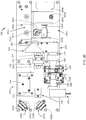
FIGs. 2A ,2B ,2C are isometric, top, and side views, respectively, of optical and electro-optical elements of the light projector according to an embodiment of the present invention; -
FIG. 2D is a cross-sectional view of an optical and electro-optical elements of the light projector according to an embodiment of the present invention; -
FIG. 3 is an isometric view of electrical components within the light projector according to an embodiment of the present invention; -
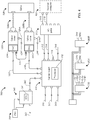
FIG.4 is an electrical block diagram of the light projector according to an embodiment of the present invention; -
FIG. 5A, FIG. 5B and FIG. 5C are illustrations showing three different line widths obtained an object in a procedure for adjusting focusing of the light emitted by the light projector on an object according to an embodiment of the present invention; and -
FIG. 6A, FIG. 6B and FIG. 6C are plots showing relative optical power returned as a function of scanning position for the three focusing conditions ofFIG. 5A, FIG. 5B and FIG. 5C according to an embodiment of the present invention. - The detailed description explains embodiments of the disclosure, together with advantages and features, by way of example with reference to the drawings.
- Embodiments of the present invention provide improved operating range and operating consistency for a light projector device.
-
FIGs. 1A, 1B, 1C are isometric, front, and bottom views of alight projector 10 according to an embodiment of the present invention. In an embodiment, thelight projector 10 includes afront cover 20, awindow 25, abase housing 30, afan assembly 40, andventing slots 50. In an embodiment, a beam of light is sent out of and returned back through thewindow 25. -
FIGs. 2A ,2B ,2C ,2D are isometric, top, side, and cross-sectional views, respectively, of an electro-optical plate assembly 200 within thelight projector 10. In an embodiment, thelight projector 10 includes amounting plate 202, alight source assembly 210, fold mirror assemblies, 220A, 220B, expandinglens assembly 230, collimating/focusinglens assembly 240,beamsplitter assembly 250, two-axis beam-steering assembly 260,reflector mirror assembly 270,focusing lens assembly 275, - In an embodiment, the
light source assembly 210 includes alight source 212 and amounting block 214. In an embodiment, thelight source 212 is a diode-pumped solid state laser (DPSS) that emits a round beam of green laser light having a wavelength of about 532 nm. In other embodiments, thelight source 212 is a different type of laser such as a diode laser or is a non-laser source. In an embodiment, thefold mirror assemblies fold mirrors adjustable mirror mounts fold mirrors beam expander 230, which includes abeam expander lens 234 and abeam expander mount 232. The expanded beam of light from the beam expander 230 travels through a collimating/focusinglens assembly 240, which acts to focus the beam leaving thelight projector 10 onto an object of interest. Because the light leaving thelight projector 10 is relatively far from thelight projector 10, the beam of light is nearly collimated and converges relatively slowly to a focused spot. In an embodiment, the collimating/focusinglens assembly 240 includes alens 241, alens mount 242, and a motorized focusingstage 243. The motorized focusingstage 243 adjusts the position of thelens 241 andlens mount 242 to focus the beam of light onto the object of interest. In an embodiment, the motorized focusingstage 243 includes a servomotor assembly 244 that drives arotary actuator 245 attached toshaft 246 affixed to anattachment 247. As therotary actuator 245 rotates, it causes thelens mount 242 to be translated on aball slide 248. - In an embodiment, the
beamsplitter assembly 250 includesentrance aperture 251A,exit aperture 251B, and beamsplitter 252. In an embodiment, the beamsplitter 252 is a 50/50 beamsplitter, which is to say that the beamsplitter 252 transmits half and reflects half the incident optical power. Half of the light arriving at thebeamsplitter assembly 250 from the collimating/focusinglens assembly 240 is reflected onto abeam absorber assembly 255, which absorbs almost all the light, thereby keeping unwanted reflected light from passing back into the electro-optical plate assembly 200. In an embodiment, thebeam absorber assembly 255 includes aneutral density filter 256, a felt absorber 257, and a felt absorber 258. - The two-axis beam-
steering assembly 260 includesbeam steering assemblies beam steering assembly light weight mirror mirror mount motor position detector mounting block first mirror 261A steers the beam of light to thesecond mirror 261B, which steers the beam out of thewindow 25 to the object of interest. The beam-steering assembly 260 steers the beam in each of two orthogonal axes, sometimes referred to as x-y axes. In an embodiment, the beam-steering assembly 260 is provided steering directions to move the beam of light in a predetermined pattern by a processor 312 (FIG. 4 ). Light reflected or scattered off the object of interest retraces the outgoing path, striking first themirror 261B and then themirror 261A before passing through theexit aperture 251B, and reflecting off the beamsplitter 252. Beam steering assemblies such as 260A, 260B are also each referred to as galvanometers or galvos, which is an electromechanical device that works as an actuator that produces a rotary deflection, in this case of themirrors - The
mirror assembly 270 includesmount 271 andreturn mirror 272. The focusingmirror assembly 275 includes focusinglens 276 andlens mount 277. In an embodiment, light arriving at thereturn mirror 272 from the beamsplitter 252 passes through the focusinglens 276. In an embodiment, the focusinglens 276 is a doublet. In an embodiment, anopaque cone 280 smoothly slides overlens mount 277 and attaches rigidly toadjustment stage 285. The purpose of theopaque cone 280 is to block background light from within thelight projector 10 from contaminating the light emitted by thelight source 210 and reflected off the object of interest and passing through thelens 276. Aperture assembly includesaperture 291 andaperture mount 292. In an embodiment, theaperture assembly 290 is rigidly affixed to theoptical detector assembly 295 by aninterface element 292. In an embodiment, theaperture assembly 290 is further rigidly coupled to theadjustment stage 285. Theadjustment stage 285 is adjusted in the x direction by anx adjuster 286, in the y direction by ay adjuster 287, and in the z direction by az adjuster 288. The purpose of theadjustment stage 285 is to adjust the position of theaperture 291 and theoptical detector assembly 295 in x, y, and z relative to the beam of light to enable the focused beam oflight 281 to pass through the aperture for the object of interest located within the rated range of distances of the object being scanned with the light from thelight projector 10. The purpose of the aperture is to block unwanted background light, especially light scattered from within the enclosure of thelaser projector 10, for example, off the mirrors 216A, 216B, the beamsplitter 252, the components of thebeam block 255, thereturn mirror 272, and the focusinglens 276. In addition, theaperture 291 helps to block unwanted background light from the environment outside the enclosure of thelight projector 10. Examples of such unwanted background light blocked by the aperture include artificial light and sunlight, both direct and reflected. - In an embodiment, the
aperture 291 is a circular aperture. In an embodiment, the circular aperture has a diameter of 150 micrometers and a centering accuracy of +/- 20 micrometers. A circular aperture is often referred to as a pinhole, and theelement 291 may alternatively be referred to as an aperture or a pinhole. In other embodiments, the aperture is not circular but has another shape. - The
optical detector assembly 295 receives light on an optical detector within theassembly 295 and produces an electrical signal in response. In an embodiment, the optical detector is a photomultiplier tube (PMT). In an embodiment, the PMT is includes a high-voltage supply circuit and a low-noise amplifier. In an embodiment, the amplifier is connected close to the PMT anode output pin to reduce the effect of external noise on the produced electrical signal. In an embodiment, the PMT is a Hamamatsu H11903 photosensor manufactured by Hamamatsu Photonics K.K., with headquarters in Shimokanzo, Japan. An advantage of a PMT for the present application includes high sensitivity to small optical powers and ability to measure both very weak optical signals and very strong optical signals. In an embodiment, the gain of the PMT can be adjusted by a factor of 100,000 or more according to the selected gain level, which is determined by the voltage applied to the PMT. This wide range of achievable gains enables the light projector to measure object regions ranging from dark black to bright white or shiny (i.e. highly reflective). - As explained herein above, the motorized focusing
stage 243 adjusts the position of thelens 241 and lens mount 242 to focus the beam of light from thelight projector 10 onto the object of interest. A method for determining the correct focusing position for themotorized stage 243 is now described with reference toFIG. 5A, FIG. 5B, and FIG. 5C andFIG. 6A, FIG. 6B, and FIG. 6C . In an embodiment, the motorized focusingstage 243 adjusts the position of the collimating/focusinglens assembly 240 to each of several positions, thereby producing scanning lines of different widths as illustrated inFIG. 5A, FIG. 5B, and FIG. 5C. FIG. 5A shows the case in which the scanning line is adjusted to its minimum width, whileFIG. 5B and FIG. 5C illustrate wider out-of-focus scanner lines produced by non-optimum focusing of thelens 241 by the motorized focusingstage 243. In an embodiment, the desired focusing of the collimating/focusinglens assembly 240 is found by stepping thelens 241 to each of several positions. At each of those positions, the galvo mirrors 261A, 261B are used to steer the projected light along a line. An example is shown inFIG. 6A, FIG. 6B, and FIG. 6C , where the observed relative optical powers observed for each correspond to the levels of focus illustrated inFIG. 5A, FIG. 5B, and FIG. 5C , respectively. As can be seen inFIG. 5A - FIG. 5C andFIG. 6A - FIG. 6C , improved focus corresponds to relatively larger variations in the returned optical power as received by theoptical detector assembly 295 as the beam is steered from point to point on the object of interest. Note that the average level of optical power in each ofFIG. 6A, FIG. 6B, and FIG. 6C is the same, namely about 2.0 arbitrary units (au), in each ofFIG. 6A, FIG. 6B, and FIG.6C . In contrast, the peak relative optical power observed inFIG. 6A in around 5.0 au, around 3.0 au higher than the average value, while the peak relative optical power observed inFIG. 6C is only around 2.5 au, which is only around 0.5 au higher than the average relative optical power. Without being bound to a particular theory, it is believed the reason for this change in relative optical power level is speckle, which is an effect in which laser light scattered off different portions of an object interfere constructively or destructively to produce the fluctuations in returned optical power. When a laser beam is focused, the relative change in the returned optical power is increased as the beam is swept along the object. In an embodiment, the motorized focusingstage 243 is adjusted until the maximum change in relative optical power is achieved in scanning a line. This ensures that thelens 241 has been adjusted to the position of optimal focus. - In an embodiment, a pre-scan is performed to determine the desired level of gain for a given scan region. For example, if a region is scanned with some elements in the region having a relatively high reflectance, for example because the elements are white, the gain of the PMT is set to a relatively low value since the optical power returned to the PMT is relatively high. On the other hand, if scanning is performed on a region containing only elements having relatively low reflectance, for example because the elements are black or dark, the gain of the PMT is set to a relatively high value. In an embodiment, a pre-scan is performed on a region to be measured as a way to obtain relatively high measurement sensitivity without saturating the PMT. In other words, the use of a pre-scan enables relatively dark objects to be measured even at relatively large distances from the
light projector 10. When a region includes both white or light objects as well as black or dark objects, in an embodiment, the region may be broken into sub-regions, with separate scans performed for at least some of the sub-regions. - The light from the
light source 212 that leaves thelight projector 10 travels to the object of interest and scatters off the object in a solid angle, afterwards retracing its path as it returns to thelight projector 10. After reflecting off themirrors exit aperture 251B. The light then reflects off beam splitter 252 before passing through thelens 276 to form the focusedlight beam 281. The direction of focusedlight beam 281 is determined by the path from a first point at which light from thelight projector 10 strikes the object to a second point through the center of the entrance pupil of thelens 276. In an embodiment, theaperture 291 is further aligned to the path that extends from the first point to the second point and into theoptical detector assembly 295. Furthermore, in an embodiment, the position of theaperture 291 as adjusted in the z direction to cause the beam waist of the returning beam of light to pass through theaperture 291 when the object is in the range of 5 to 7 meters from thelight projector 10. In an embodiment, theaperture 291 is large enough to pass nearly all of the return light through theexit aperture 251B onto the active area of the optical detector at the range of 5 to 7 meters. In an embodiment, the light begins to clip slightly at larger distances such as 10 to 15 meters from thelight projector 10. At distances closer to thelight projector 10 than 5 meters, the light will clip more significantly, but this is not usually a problem because the optical power scattered off an object point closer than 5 meters has larger scattered intensity than light scattered off an object point farther from thelight projector 10. - In an embodiment, the
aperture 291 is rigidly affixed to theaperture assembly 290, which in turn is rigidly affixed to theoptical detector assembly 295. In an embodiment, theoptical detector assembly 295 andaperture assembly 290 are further aligned to ensure that returning light passing through the center of the entrance pupil of thelens 276 not only passes through the center ofaperture 291 but also the center of the active area of the optical detector in theoptical detector assembly 295. As a result, the range of operation of thelight projector 10 is made as large as possible. This is to say that the rigid attachment of theaperture 291 to thephotodetector assembly 295 in combination with alignment of theaperture 291, thephotodetector assembly 295, thelens 276, and theexit aperture 251B helps to ensure that the best sensitivity is obtained for objects both near to and far from thelight projector 10. With this alignment, the pre-scan is also expected to give consistent results in determining the PMT gain settings required for each combination of object distance and object reflectance. -
FIG. 3 is an isometric view of theelectrical assembly 300 within thelight projector 10, andFIG. 4 is an electrical block diagram for thelight projector 10. Theelectrical assembly 300 includes an electronics plate 302 and a number of circuit boards including acarrier board 310,first galvo driver 320A,second galvo driver 320B,analog circuit 340,multi-voltage power supply 350, +24volt power supply 360A, and -24volt power supply 360B. The circuit block diagram representation for theelectrical assembly 300 is shown inFIG. 4 . Thecarrier board 310 includes aprocessor 312 that controls many functions within thelight projector 10.Control cables carrier board 310 to digital-to-analog converters (DACs) 324A, 324B on the first and secondgalvo driver boards carrier board 310 to theDACs mirrors galvo drivers components 328 throughcables jumper cable 232 is used to connect the first and secondgalvo driver boards - The
analog circuit board 340 includes an analog-to-digital converter (ADC) 341. TheADC 341 receives an analog electrical signals from theoptical detector 295, which in an embodiment is a PMT. TheADC 341 converts the analog signals into digital electrical signals, which it sends over anEthernet cable 342 to thecarrier board 310. The carrier board provides the digital data to theprocessor 312 and, in an embodiment, to an external computer attached to input/output (I/O)panel 370 through aUSB cables Ethernet cable processor 312 orexternal computer 420 constructs a gray-scale image of the optical powers received byoptical detector 295. Such an image may be displayed to a user, may be used to identify features in the scanned object, and may be used for other functions such as setting the position of the focusinglens 241 with the motorized focusingstage 243. In an embodiment, theanalog circuit board 340 receives voltages over thecable 343 from themulti-voltage power supply 350. In an embodiment, thecarrier board 310 further provides control signals to the motorized focusingstage 243 over thecable 317 and control signals to thelight source 212 over thecable 318. Aconnector 316 is attached to the circuit board to override the laser bypass circuit. In an embodiment, thecarrier board 310 is further provided with acable 319 operable to send a signal to reset the software on the carrier board. Thecarrier board 310 receives voltages over thecable 311 from themulti-voltage power supply 350. In an embodiment, additional voltages are provided from themulti-voltage power supply 350 to the I/O panel 370 and to thefan assembly 380. - The term "about" is intended to include the degree of error associated with measurement of the particular quantity based upon the equipment available at the time of filing the application. For example, "about" can include a range of ± 8% or 5%, or 2% of a given value.
- The terminology used herein is for the purpose of describing particular embodiments only and is not intended to be limiting of the disclosure. As used herein, the singular forms "a", "an" and "the" are intended to include the plural forms as well, unless the context clearly indicates otherwise. It will be further understood that the terms "comprises" and/or "comprising," when used in this specification, specify the presence of stated features, integers, steps, operations, elements, and/or components, but do not preclude the presence or addition of one or more other features, integers, steps, operations, element components, and/or groups thereof.
- While the disclosure is provided in detail in connection with only a limited number of embodiments, it should be readily understood that the disclosure is not limited to such disclosed embodiments. Rather, the disclosure can be modified to incorporate any number of variations, alterations, substitutions or equivalent arrangements not heretofore described, but which are commensurate with the spirit and scope of the disclosure. Additionally, while various embodiments of the disclosure have been described, it is to be understood that the exemplary embodiment(s) may include only some of the described exemplary aspects. Accordingly, the disclosure is not to be seen as limited by the foregoing description, but is only limited by the scope of the appended claims.
Claims (15)
- An apparatus comprising:a light source operable to emit a beam of outgoing light;a beam-steering system operable to steer the beam of outgoing light onto an object;a first focusing lens operable to receive light returned from the object;an aperture operable to receive light from the first focusing lens; andan optical detector rigidly coupled to the aperture.
- The apparatus of claim 1 further comprising an adjustment stage operable to adjust a position of the aperture and the optical detector.
- The apparatus of claim 1 further comprising an opaque cone rigidly coupled to the aperture.
- The apparatus of claim 1 wherein the aperture is a circular aperture.
- The apparatus of claim 1 wherein the beam-steering system comprises a pair of mirrors, each mirror coupled to a galvanometer, each galvanometer having a motor and a position sensor.
- The apparatus of claim 1 further comprising a second lens assembly operable to focus the beam of outgoing light on the object.
- The apparatus of claim 6 wherein the second lens assembly further comprises:a second lens operable to receive light generated by the light source; anda motorized focusing stage operable to adjust a position of the second lens to focus the beam of outgoing light on the object.
- The apparatus of claim 1 wherein the optical detector comprises a photomultiplier tube.
- A method comprising:providing a light source, a beam-steering system, a first focusing lens, an aperture, and an optical detector rigidly coupled to the aperture;emitting a beam of outgoing light with the light source;steering the beam of outgoing light onto an object with the beam-steering system;receiving through the first focusing lens light returned from the object; andsending the returned light through the aperture and onto the optical detector.
- The method of claim 9 further comprising aligning the aperture to pass the light received from the first focusing lens through a center of the aperture.
- The method of claim 9 further comprising aligning the optical detector to center received light onto an active area of the optical detector.
- The method of claim 9 further comprising:providing an adjustment stage; andadjusting the position of the aperture with the adjustment stage.
- The method of claim 12 further comprising:aligning the position of the optical detector to center light received through the aperture onto an active area of the optical detector; andrigidly affixing the optical detector to the aperture.
- The method of claim 9 further comprising focusing the beam of outgoing light onto the object with a second lens assembly, the second lens assembly having a second lens and a motorized focusing stage, preferably the method further comprising adjusting a position of the second lens with a motorized focusing stage, and preferably the method further comprising adjusting the position of the second lens based at least in part on relative change in optical power received by the optical detector as the focused beam of light is moved on the object.
- The method of claim 9 further comprising:providing a processor; andsteering the beam of outgoing light onto an object in a predetermined pattern based at least in part on steering directions provided by the processor.
Applications Claiming Priority (1)
| Application Number | Priority Date | Filing Date | Title |
|---|---|---|---|
| US16/017,360 US10884257B2 (en) | 2018-06-25 | 2018-06-25 | Background light suppression for a laser projector |
Publications (2)
| Publication Number | Publication Date |
|---|---|
| EP3588944A2 true EP3588944A2 (en) | 2020-01-01 |
| EP3588944A3 EP3588944A3 (en) | 2020-02-26 |
Family
ID=66821098
Family Applications (1)
| Application Number | Title | Priority Date | Filing Date |
|---|---|---|---|
| EP19179454.4A Withdrawn EP3588944A3 (en) | 2018-06-25 | 2019-06-11 | Laser projector |
Country Status (2)
| Country | Link |
|---|---|
| US (1) | US10884257B2 (en) |
| EP (1) | EP3588944A3 (en) |
Families Citing this family (4)
| Publication number | Priority date | Publication date | Assignee | Title |
|---|---|---|---|---|
| US11892621B2 (en) | 2019-10-24 | 2024-02-06 | Faro Technologies, Inc. | Trajectory and control optimizations for reduced power |
| US11552439B2 (en) | 2019-10-24 | 2023-01-10 | Faro Technologies, Inc. | Laser projector |
| US11867499B2 (en) * | 2020-02-19 | 2024-01-09 | Faro Technologies, Inc. | System and method for verifying a position of a component on an object |
| US11921409B2 (en) | 2021-04-13 | 2024-03-05 | Faro Technologies, Inc. | Laser projector system |
Family Cites Families (14)
| Publication number | Priority date | Publication date | Assignee | Title |
|---|---|---|---|---|
| US5225923A (en) | 1992-07-09 | 1993-07-06 | General Scanning, Inc. | Scanning microscope employing improved scanning mechanism |
| AU2582301A (en) | 1999-12-16 | 2001-06-25 | Iridian Technologies, Inc. | Lens alignment system for solid state imager |
| US6547397B1 (en) | 2000-04-19 | 2003-04-15 | Laser Projection Technologies, Inc. | Apparatus and method for projecting a 3D image |
| US7372558B2 (en) | 2001-10-11 | 2008-05-13 | Laser Projection Technologies, Inc. | Method and system for visualizing surface errors |
| CA2596284C (en) | 2005-02-01 | 2016-07-26 | Laser Projection Technologies, Inc. | Laser projection with object feature detection |
| US8085388B2 (en) | 2005-02-01 | 2011-12-27 | Laser Projection Technologies, Inc. | Laser radar projection with object feature detection and ranging |
| US7834867B2 (en) | 2006-04-11 | 2010-11-16 | Microvision, Inc. | Integrated photonics module and devices using integrated photonics modules |
| WO2009133690A1 (en) | 2008-04-30 | 2009-11-05 | 日本電産サンキョー株式会社 | Optical unit having deflection correcting function, and photographing optical device |
| US9019503B2 (en) * | 2010-04-19 | 2015-04-28 | The United States Of America, As Represented By The Secretary Of The Navy | MEMS microdisplay optical imaging and sensor systems for underwater and other scattering environments |
| GB201100555D0 (en) | 2011-01-13 | 2011-03-02 | Optos Plc | Improvements in or relating to Ophthalmology |
| US20150085108A1 (en) | 2012-03-24 | 2015-03-26 | Laser Projection Technologies | Lasergrammetry system and methods |
| WO2015021173A1 (en) | 2013-08-06 | 2015-02-12 | Laser Projection Technologies, Inc. | Virtual laser projection system and method |
| US9423278B1 (en) | 2015-03-09 | 2016-08-23 | Laser Projection Technologies, Inc. | 3D laser projection, scanning and object tracking |
| CN107923737B (en) | 2015-12-13 | 2019-12-17 | 富通尼奥有限责任公司 | Method and apparatus for superpixel modulation and ambient light suppression |
-
2018
- 2018-06-25 US US16/017,360 patent/US10884257B2/en active Active
-
2019
- 2019-06-11 EP EP19179454.4A patent/EP3588944A3/en not_active Withdrawn
Also Published As
| Publication number | Publication date |
|---|---|
| US10884257B2 (en) | 2021-01-05 |
| US20190391409A1 (en) | 2019-12-26 |
| EP3588944A3 (en) | 2020-02-26 |
Similar Documents
| Publication | Publication Date | Title |
|---|---|---|
| US12332381B2 (en) | 3D sensing | |
| US10884257B2 (en) | Background light suppression for a laser projector | |
| US7701592B2 (en) | Method and apparatus for combining a targetless optical measurement function and optical projection of information | |
| US8681344B2 (en) | Devices and methods for position determination and surface measurement | |
| JP2004028995A (en) | Electro-optical parallel optical axis type distance measuring system | |
| US11531208B2 (en) | Light source, optical device, measuring device, robot, electronic apparatus, movable structure, and manufacturing apparatus | |
| US20140253719A1 (en) | Galvanometer scanned camera with variable focus and method | |
| CA2620941A1 (en) | Imaging system and method | |
| WO2015165608A1 (en) | 3d coarse laser scanner | |
| CN110297303B (en) | Apparatus system and method for aligning lens assembly within chassis | |
| CN106405825B (en) | Adaptive laser far field power density control device | |
| JP2020034310A (en) | Optical devices, measuring devices, robots, electronic devices, moving objects, and modeling devices | |
| CN110500971A (en) | Roughness concentration probe and its use and the coordinate measuring system with the probe | |
| JPH11218686A (en) | Optical image recording device and method utilising the device | |
| US12164033B2 (en) | Lidar projection apparatus | |
| US11867499B2 (en) | System and method for verifying a position of a component on an object | |
| EP3833017B1 (en) | Laser projector system | |
| EP4315844B1 (en) | Laser projector system | |
| US20240378754A1 (en) | Calibration of actuation mechanism | |
| JP2021184009A (en) | Image projection device | |
| Muth | Optimized x/y scanning head for laser beam positioning | |
| JP3817232B2 (en) | Displacement measuring device | |
| KR20210042230A (en) | Laser Processing Apparatus | |
| JP2022071666A (en) | Optical equipment, measuring equipment, robots, electronic equipment and modeling equipment | |
| GB2614527A (en) | Calibration of actuation mechanism |
Legal Events
| Date | Code | Title | Description |
|---|---|---|---|
| PUAI | Public reference made under article 153(3) epc to a published international application that has entered the european phase |
Free format text: ORIGINAL CODE: 0009012 |
|
| STAA | Information on the status of an ep patent application or granted ep patent |
Free format text: STATUS: THE APPLICATION HAS BEEN PUBLISHED |
|
| AK | Designated contracting states |
Kind code of ref document: A2 Designated state(s): AL AT BE BG CH CY CZ DE DK EE ES FI FR GB GR HR HU IE IS IT LI LT LU LV MC MK MT NL NO PL PT RO RS SE SI SK SM TR |
|
| AX | Request for extension of the european patent |
Extension state: BA ME |
|
| PUAL | Search report despatched |
Free format text: ORIGINAL CODE: 0009013 |
|
| AK | Designated contracting states |
Kind code of ref document: A3 Designated state(s): AL AT BE BG CH CY CZ DE DK EE ES FI FR GB GR HR HU IE IS IT LI LT LU LV MC MK MT NL NO PL PT RO RS SE SI SK SM TR |
|
| AX | Request for extension of the european patent |
Extension state: BA ME |
|
| RIC1 | Information provided on ipc code assigned before grant |
Ipc: H04N 9/31 20060101AFI20200123BHEP |
|
| STAA | Information on the status of an ep patent application or granted ep patent |
Free format text: STATUS: REQUEST FOR EXAMINATION WAS MADE |
|
| 17P | Request for examination filed |
Effective date: 20200507 |
|
| RBV | Designated contracting states (corrected) |
Designated state(s): AL AT BE BG CH CY CZ DE DK EE ES FI FR GB GR HR HU IE IS IT LI LT LU LV MC MK MT NL NO PL PT RO RS SE SI SK SM TR |
|
| STAA | Information on the status of an ep patent application or granted ep patent |
Free format text: STATUS: EXAMINATION IS IN PROGRESS |
|
| 17Q | First examination report despatched |
Effective date: 20211202 |
|
| GRAP | Despatch of communication of intention to grant a patent |
Free format text: ORIGINAL CODE: EPIDOSNIGR1 |
|
| STAA | Information on the status of an ep patent application or granted ep patent |
Free format text: STATUS: GRANT OF PATENT IS INTENDED |
|
| INTG | Intention to grant announced |
Effective date: 20231107 |
|
| STAA | Information on the status of an ep patent application or granted ep patent |
Free format text: STATUS: THE APPLICATION IS DEEMED TO BE WITHDRAWN |
|
| 18D | Application deemed to be withdrawn |
Effective date: 20240308 |