EP3588924A1 - An apparatus, system and method of call notifications to active communication devices - Google Patents
An apparatus, system and method of call notifications to active communication devices Download PDFInfo
- Publication number
- EP3588924A1 EP3588924A1 EP18211671.5A EP18211671A EP3588924A1 EP 3588924 A1 EP3588924 A1 EP 3588924A1 EP 18211671 A EP18211671 A EP 18211671A EP 3588924 A1 EP3588924 A1 EP 3588924A1
- Authority
- EP
- European Patent Office
- Prior art keywords
- call
- communication device
- link
- active
- notification
- Prior art date
- Legal status (The legal status is an assumption and is not a legal conclusion. Google has not performed a legal analysis and makes no representation as to the accuracy of the status listed.)
- Granted
Links
- 238000004891 communication Methods 0.000 title claims abstract description 101
- 238000000034 method Methods 0.000 title claims description 51
- 230000000694 effects Effects 0.000 claims abstract description 47
- 238000004590 computer program Methods 0.000 claims description 5
- 238000012790 confirmation Methods 0.000 claims 2
- 238000012545 processing Methods 0.000 description 13
- 230000004044 response Effects 0.000 description 13
- 230000015654 memory Effects 0.000 description 8
- 238000012546 transfer Methods 0.000 description 6
- 230000000977 initiatory effect Effects 0.000 description 4
- 230000005540 biological transmission Effects 0.000 description 3
- 230000001413 cellular effect Effects 0.000 description 3
- 238000010586 diagram Methods 0.000 description 3
- 238000010295 mobile communication Methods 0.000 description 3
- 238000001514 detection method Methods 0.000 description 2
- 238000005516 engineering process Methods 0.000 description 2
- 230000003287 optical effect Effects 0.000 description 2
- 230000002085 persistent effect Effects 0.000 description 2
- 230000000007 visual effect Effects 0.000 description 2
- 238000003490 calendering Methods 0.000 description 1
- 230000008859 change Effects 0.000 description 1
- 238000004880 explosion Methods 0.000 description 1
- 230000006870 function Effects 0.000 description 1
- 239000004973 liquid crystal related substance Substances 0.000 description 1
- 239000000463 material Substances 0.000 description 1
- 238000012986 modification Methods 0.000 description 1
- 230000004048 modification Effects 0.000 description 1
- 230000008569 process Effects 0.000 description 1
Images


Classifications
-
- H—ELECTRICITY
- H04—ELECTRIC COMMUNICATION TECHNIQUE
- H04M—TELEPHONIC COMMUNICATION
- H04M3/00—Automatic or semi-automatic exchanges
- H04M3/42—Systems providing special services or facilities to subscribers
- H04M3/42229—Personal communication services, i.e. services related to one subscriber independent of his terminal and/or location
- H04M3/42263—Personal communication services, i.e. services related to one subscriber independent of his terminal and/or location where the same subscriber uses different terminals, i.e. nomadism
-
- H—ELECTRICITY
- H04—ELECTRIC COMMUNICATION TECHNIQUE
- H04M—TELEPHONIC COMMUNICATION
- H04M3/00—Automatic or semi-automatic exchanges
- H04M3/42—Systems providing special services or facilities to subscribers
- H04M3/42365—Presence services providing information on the willingness to communicate or the ability to communicate in terms of media capability or network connectivity
-
- H—ELECTRICITY
- H04—ELECTRIC COMMUNICATION TECHNIQUE
- H04M—TELEPHONIC COMMUNICATION
- H04M3/00—Automatic or semi-automatic exchanges
- H04M3/42—Systems providing special services or facilities to subscribers
- H04M3/54—Arrangements for diverting calls for one subscriber to another predetermined subscriber
- H04M3/543—Call deflection
-
- H—ELECTRICITY
- H04—ELECTRIC COMMUNICATION TECHNIQUE
- H04L—TRANSMISSION OF DIGITAL INFORMATION, e.g. TELEGRAPHIC COMMUNICATION
- H04L51/00—User-to-user messaging in packet-switching networks, transmitted according to store-and-forward or real-time protocols, e.g. e-mail
- H04L51/21—Monitoring or handling of messages
- H04L51/224—Monitoring or handling of messages providing notification on incoming messages, e.g. pushed notifications of received messages
-
- H—ELECTRICITY
- H04—ELECTRIC COMMUNICATION TECHNIQUE
- H04M—TELEPHONIC COMMUNICATION
- H04M3/00—Automatic or semi-automatic exchanges
- H04M3/42—Systems providing special services or facilities to subscribers
- H04M3/436—Arrangements for screening incoming calls, i.e. evaluating the characteristics of a call before deciding whether to answer it
-
- H—ELECTRICITY
- H04—ELECTRIC COMMUNICATION TECHNIQUE
- H04M—TELEPHONIC COMMUNICATION
- H04M7/00—Arrangements for interconnection between switching centres
- H04M7/0024—Services and arrangements where telephone services are combined with data services
- H04M7/0033—Notification or handling of incoming calls by a computer
Definitions
- the specification relates generally to communication devices, and specifically to an apparatus, system and method of call notifications to active communication devices.
- An aspect of the specification provides an apparatus comprising: a processor and a communication interface, the processor enabled to: receive a call for a first device via the communication interface; determine that a second device is active; and transmit a notification of the call to the second device.
- the processor can be further enabled to determine that the second device is active by receiving an indication of activity from one or more of the second device and a server enabled to communicate with the first device and the second device.
- the indication of activity can comprise one or more of: active typing data, motion sensor data, presence data, and human-machine interface data.
- the processor can be further enabled to determine that the second device is active by transmitting a query to the second device and receiving a response thereto.
- the query can comprise a request for capabilities of the second device and the processor can be further enabled to transmit the notification of the call to the second device when the response is indicative that the second device is capable of processing the call.
- the processor can be further enabled to: determine that the second device is both active and capable of handling the call; and, transmit the notification of the call to the second device when the second device is both active and capable of handling the call.
- the notification can be enabled to trigger a selectable option displayed at the second device for transferring the call to the second device.
- the processor can be further enabled to: place the call on hold; and transmit a second notification to a calling device, the second notification indicative of one or more of instructions for waiting and a wait period for answering the call.
- the apparatus can further comprise the first device.
- the apparatus can further comprise a server enabled to: communicate with the first device and the second device; and, transfer the call to one or more of the first device and the second device.
- Another aspect of the specification provides a method comprising: at an apparatus comprising a processor and a communication interface, receiving a call for a first device via the communication interface; determining, at the processor, that a second device is active; and transmitting a notification of the call to the second device.
- the method can further comprise determining that the second device is active by receiving an indication of activity from one or more of the second device and a server enabled to communicate with the first device and the second device.
- the indication of activity can comprise one or more of: active typing data, motion sensor data, presence data, and human-machine interface data.
- the method can further comprise determining that the second device is active by transmitting a query to the second device and receiving a response thereto.
- the query can comprise a request for capabilities of the second device and the method further comprises transmitting the notification of the call to the second device when the response is indicative that the second device is capable of processing the call.
- the method can further comprise: determining that the second device is both active and capable of handling the call; and, transmitting the notification of the call to the second device when the second device is both active and capable of handling the call.
- the notification can be enabled to trigger a selectable option displayed at the second device for transferring the call to the second device.
- the method can further comprise: placing the call on hold; and transmitting a second notification to a calling device, the second notification indicative of one or more of instructions for waiting and a wait period for answering the call.
- the method can further comprise: communicating with the first device and the second device; and, transferring the call to one or more of the first device and the second device.
- a further aspect of the specification provides a computer program product, comprising a computer usable medium having a computer readable program code adapted to be executed to implement a method comprising: at an apparatus comprising a processor and a communication interface, receiving a call for a first device via the communication interface; determining, at the processor, that a second device is active; and transmitting a notification of the call to the second device.
- the computer program product can be non-transitory.
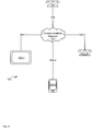
- Fig. 1 depicts a system 100 for transmitting call notifications to active devices, according to non-limiting implementations.
- System 100 comprises a communication device 101 enabled to communicate with at least one of a plurality of communication devices 103-1, 103-2, 103-3, via link 106, a communication network 107, and respective links 108-1, 108-2, 108-3.
- Communication device 101 will be also referred to hereafter as device 101. This convention will be used elsewhere in the present specification.
- Devices 103-1, 103-2, 103-3 will also be referred to hereafter generically as a device 103, and collectively as devices 103.
- links 108-1, 108-2, 108-3 will also be referred to hereafter generically as a link 108, and collectively as links 108.
- Communications network 107 will also be referred to hereafter as network 107. It is further appreciated that at least one of devices 103 is generally enabled to: receive a call, for example from device 101; determine that a second device 103 is active; and transmit a notification of the call to the second device 103. It is further appreciated that the notification can be transmitted only when the second device 103 is active, and the notification is not transmitted when the second device 103 is inactive.
- Device 101 can be any type of electronic device that can be used in a self-contained manner to make calls, for example audio calls, video calls, and the like to one or more of devices 103.
- any suitable calls are within the scope of present implementations, including, but not limited to, telephone calls, audio calls, video calls, video chats, PSTN (public switch telephone network) calls, packet based calls, and the like.
- device 101 comprises any suitable communication device for communicating with devices 103 including but not limited to any suitable combination of computing devices, personal computers, laptop computers, portable electronic devices, mobile computing device, portable computing devices, tablet computing devices, laptop computing devices, desktop phones, telephones, PDAs (personal digital assistants), cellphones, smartphones, "smart televisions" and the like.
- Other suitable communication devices are within the scope of present implementations.
- Each of devices 103 can be any type of electronic device that can be used in a self-contained manner to interact with a communications network, including but not limited to network 107, via a respective link 108. It is hence appreciated that each device 103 comprises any suitable communication device for communicating with network 107, device 101, and, in some implementations, other devices 103. Each device 103 can include, but is not limited to, any suitable combination of computing devices, personal computers, laptop computers, portable electronic devices, mobile computing device, portable computing devices, tablet computing devices, laptop computing devices, desktop phones, telephones, PDAs (personal digital assistants), cellphones, smartphones" smart televisions” and the like. Other suitable communication devices are within the scope of present implementations.
- system 100 can comprise any suitable number of communication devices. It is further appreciated that devices 103 can be associated. For example, each of devices 103 can be associated with a user thereof, and hence be associated with one another, for example via a technical association, a database, a list, association data and the like, as will be described below. However, in other implementations association of devices 103 can be via any suitable association; for example each of devices 103 can be a device associated with a corporate entity, including but not limited to a call centre. Hence, devices 103 could be associated with multiple users but within a corporate entity, or the like.
- the association between devices 103 is appreciated to be via a technical association, a database, a list, association data and the like, as will be described below, without necessarily specifying the user, corporate entity or the like in the association.
- at least one of devices 103 can be enabled to determine whether other of associated devices 103 are active.
- at least one of devices 103 can be enabled to determine capabilities of other devices 103 and further whether another of devices 103 is capable of processing a given call, as will presently be described.
- Each link 106, 108 comprises any suitable link with network 107, including any suitable combination of wired and/or wireless links, wired and/or wireless devices and/or wired and/or wireless networks, including but not limited to any suitable combination of USB (universal serial bus) cables, serial cables, wireless links, cell-phone links, cellular network links (including but not limited to 2G, 2,5G, 3G, 4G+, and the like) wireless data, Bluetooth links, NFC (near field communication) links, Wi-Fi links, WiMax links, HDMI (High-Definition Multimedia Interface), packet based links, the Internet, analog networks, the PSTN (public switched telephone network), access points, and the like, and/or a combination.
- USB universal serial bus
- serial cables wireless links
- cell-phone links cellular network links (including but not limited to 2G, 2,5G, 3G, 4G+, and the like) wireless data
- Bluetooth links including but not limited to 2G, 2,5G, 3G, 4G+, and the like
- NFC near field
- Network 107 can comprise any suitable network and/or combination of networks for conveying a call, including but not limited to audio calls and video calls, between device 101 and one or more of devices 103.
- network 107 can comprise any suitable combination of wired networks, wireless networks, cell-phone networks, cellular network networks (including but not limited to 2G, 2,5G, 3G, 4G+, and the like), Bluetooth networks, NFC (near field communication) networks, WiFi networks, WiMax networks, packet based networks, the Internet, analog networks, the PSTN (public switched telephone network), access points, and the like.
- FIG. 2 depicts a schematic diagram of a device 103-1 according to non-limiting implementations.
- Device 103-1 comprises at least one input device 200 generally enabled to receive input data, and can comprise any suitable combination of input devices, including but not limited to a keyboard, a keypad, a pointing device, a mouse, a track wheel, a trackball, a touchpad, a touch screen and the like. Other suitable input devices are within the scope of present implementations.
- processor 208 which can be implemented as a plurality of processors.
- Processor 208 is configured to communicate with a non-volatile storage unit 212 (e.g. Erasable Electronic Programmable Read Only Memory (“EEPROM”), Flash Memory) and a volatile storage unit 216 (e.g. random access memory (“RAM”).
- EEPROM Erasable Electronic Programmable Read Only Memory
- RAM random access memory
- Programming instructions 217 that implement the functional teachings of device 103-1 as described herein are typically maintained, persistently, in non-volatile storage unit 212 and used by processor 208 which makes appropriate utilization of volatile storage 216 during the execution of such programming instructions.
- processor 208 can comprise at least a portion of non-volatile storage unit 212, for example as on-board Random Access Memory (RAM).
- non-volatile storage unit 212 and volatile storage 216 are examples of computer readable media that can store programming instructions executable on processor 208. Furthermore, non-volatile storage unit 212 and volatile storage 216 are also examples of memory units and/or memory modules.
- Non-volatile storage unit 212 can further store data 218 comprising network identifiers of devices 103 with which device 103-1 is associated, for example devices 103-2, 103-3.
- Data 218 can include, but is not limited to, any suitable combination of association data, a data base, a list of associated devices 103, and the like.
- Data 218 can be generated when another device 103 is first associated with device 103-1, and then updated whenever further devices 103 are associated or disassociated with device 103-1.
- device 103-1 is enabled to process data 218 to transmit messages, queries and the like to devices 103 whose network identifiers are stored at data 218.
- data 218 can be used to exchange P2P (peer to peer) data and/or messages with devices 103 whose network identifiers are stored at data 218.
- P2P peer to peer
- data 218 stores network identifiers of devices 103-2, 103-3 and hence, devices 103-2, 103-3 have been previously associated with device 103-1 in any suitable manner.
- Processor 208 in turn can also be configured to communicate with a display 224, a microphone 22, a speaker 229, and optionally a video camera 230.
- Display 224 comprises any suitable one of or combination of CRT (cathode ray tube) and/or flat panel displays (e.g. LCD (liquid crystal display), plasma, OLED (organic light emitting diode), capacitive or resistive touchscreens, and the like).
- CTR cathode ray tube
- flat panel displays e.g. LCD (liquid crystal display), plasma, OLED (organic light emitting diode), capacitive or resistive touchscreens, and the like.
- display 224 can be enabled to display video data received from device 101 during a video call
- Microphone 226 comprises any suitable microphone and/or microphone input for receiving sound data, which can be transmitted to device 101 in one or more of an audio call and a video call.
- Speaker 229 comprises any suitable speaker for providing sound data at device 103-1, including but not limited to sound data received from device 101 in one or more of an audio call and a video call.
- Video camera 203 when present, can comprise any suitable video camera for receiving video data which can be transmitted to device 101 in a video call and/or video chat, and the like. It is appreciated that microphone 226, speaker 229 and video camera 230 can be used in combination at device 103-1 to conduct one or more of an audio call and a video call, for example with device 101.
- input device 200, display 224, microphone 226, speaker 229, and/or video camera 230 are external to device 103-1, with processor 208 in communication with each of input device 200, display 224, microphone 226, speaker 229, and/or video camera 230 via a suitable connection and/or link.
- Processor 208 also connects to a network communication interface 228, also referred to hereafter as interface 228, which can be implemented as one or more radios, and/or one or more network interface cards and/or network adapters configured to communicate over link 108-1.
- interface 2228 is configured to correspond with the network architecture that is used to implement link 108-1.
- a plurality of links with different protocols can be employed and thus interface 228 can comprise a plurality of interfaces to support each link.
- device 103-1 can be enabled to determine activity at device 103-1; determining activity can include, but is not limited to, determining whether input device 103-1 is in use (for example by determining one or of whether input data is being received at input device 200, typing activity and the like), determining whether an optional motion sensor 231 has detected motion at device 103-1.
- Motion sensor 231 can comprise any suitable motion sensor, including, but not limited to, any suitable combination of accelerometers, motion detectors, infrared sensors, and the like.
- activity can be detected via video camera 230 (e.g.
- activity when motion is detected within a field of view of video camera 230; in some implementations, activity is detected when video data received at video camera 230 meets an activity condition, for example detection of a user's face in the field of view of the video camera and the like).
- activity can be detected via microphone 226 (e.g. when sound data is received at microphone 226; in some implementations, activity is detected when sound data received at microphone 226 is above a suitable given threshold that is higher than background noise, such that background noise is filtered).
- device 103-1 can comprise one or more notification devices, including but not limited to display 224, speaker 229, and any other suitable notification device (e.g. lights, LEDs (light emitting diodes), vibration devices, haptic devices and the like (not depicted)).
- notification devices including but not limited to display 224, speaker 229, and any other suitable notification device (e.g. lights, LEDs (light emitting diodes), vibration devices, haptic devices and the like (not depicted)).
- Fig. 3 depicts a schematic diagram of device 103-2 according to non-limiting implementations. It is appreciated that device 103-2 can be substantially similar to, or different from, device 103-1. In any event, Fig. 3 is substantially similar to Fig. 2 , with like elements having like numbers, however preceded by a "3" rather than a "2"; for example, processor 308 is substantially similar to processor 208.
- device 103-2 comprises input device 300, processor 308, non-volatile storage unit 312 storing programming instructions 317, volatile storage unit 316, display 324, microphone 326, optional video camera 330, interface 328 and speaker 329, optional motion detector 331, and any suitable notification device. Further non-volatile storage unit 312 stores data 318, similar to data 218, but storing network identifiers of devices 103-1, 103-3. Hence, device 103-2 was previously associated with devices 103-1, 103-3 in any suitable manner.
- Fig. 4 depicts a schematic diagram of device 103-3 according to non-limiting implementations. It is appreciated that device 103-3 can be substantially similar to, or different from, device 103-1. In any event, Fig. 4 is substantially similar to Fig.2 , with like elements having like numbers, however preceded by a "4" rather than a "2"; for example, processor 408 is substantially similar to processor 208.
- device 103-3 comprises input device 400, processor 408, non-volatile storage unit 412 storing programming instructions 417, volatile storage unit 416, display 424, microphone 426, optional video camera 430, speaker 429, interface 428, an optional motion sensor 431, and any suitable notification device. Further non-volatile storage unit 412 stores data 418, similar to data 218, but storing network identifiers of devices 103-1, 103-2. Hence, device 103-3 was previously associated with devices 103-1, 103-2 in any suitable manner.
- Fig. 1 is further appreciated that while device 103-1 is depicted as a tablet device, device 103-2 is depicted as a mobile communication device (such as a smartphone, PDA and the like) and device 103-3 is depicted as a desktop phone and/or house phone, present implementations are not so limited. Rather, it is appreciated that Fig. 1 is an example only and that each of devices 103-1, 103-2, 103-3 can comprise any suitable communication device as described above.
- devices 103 can each be associated with a given user, for example, one of devices 103 comprising the given user's tablet device (e.g. device 103-1), one of devices 103 comprising the given user's mobile communication device (e.g. device 103-2) and one of devices 103 comprising the given user's desk telephone and/or home telephone (e.g. device 103-2).
- devices 103 comprising the given user's tablet device (e.g. device 103-1), one of devices 103 comprising the given user's mobile communication device (e.g. device 103-2) and one of devices 103 comprising the given user's desk telephone and/or home telephone (e.g. device 103-2).
- Further data indicative of the association can be stored at one or more of devices 103 (e.g. data 218, 318, 418) and/or at a network device, such as a server (not depicted, but see server 107b of Fig. 13 ).
- a network device such as a server (not depicted, but see server 107b of Fig. 13 ).
- a call from device 101 can be received at one of devices 103, such as device 103-1, while another of devices 103 are active, such as one or more of devices 103-2, 103-3, described in further detail below.
- Fig. 5 depicts a flowchart illustrating a method 500 of call notifications to active communication devices, according to non-limiting implementations.
- method 500 is performed using device 103-1.
- the following discussion of method 500 will lead to a further understanding of device 103-1 and its various components.
- device 103-1 and/or method 500 can be varied, and need not work exactly as discussed herein in conjunction with each other, and that such variations are within the scope of present implementations. It is appreciated that, in some implementations, method 500 is implemented in device 103-1 by processor 208.
- method 500 need not be performed in the exact sequence as shown, unless otherwise indicated; and likewise various blocks may be performed in parallel rather than in sequence; hence the elements of method 500 are referred to herein as “blocks” rather than “steps”. It is also to be understood that method 500 can be implemented on variations of device 103-1 as well, for example either of devices 103-2, 103-3.
- method 500 is described with reference to Figs. 6 , 7 , 8 and 10 , each of which are substantially similar to Fig. 1 , with like elements having like numbers.
- a call is received at first device 103-1, for example via interface 228.
- device 101 is generally enabled to initiate a call 601, for example one or more of a voice call and video call, to device 103-1 via network 107, for example by transmitting call initiation data to one or more switching elements, such one or more switching servers, in network 107.
- the call initiation data can include, but is not limited to, an identifier of device 103-1, a virtual number associated with a switching server (which in turn forwards the call initiation data to device 103-1), and the like.
- device 101 will transmit call initiation data over link 106, to network 107, where the call is in turn conveyed to device 103-1 via link 108-1.
- device 103-1 can optionally provide a notification of call 601, including but not limited to audio notifications, visual notifications, vibratory notifications and the like.
- processor 208 determines whether device 103-1 is active. For example, a determination of whether device 103-1 is active can include, but is not limited to, call 501 being answered at device 103-1 (such that audio data, video data and the like can be exchanged between devices 101, 103-1) an indication of activity at input device 200, a detection of motion via one or more of microphone 226, video camera 230, and/or motion sensor 231.
- method 500 ends at block 504 (i.e. a "Yes" decision at block 503). Otherwise, processor 208 determines that device 103-1 is inactive (i.e. a "No" decision at block 503).
- a determination of inactive can occur when one or more of: call 601 is unanswered at device 103-1 within a given period of time and/or after a given number of notifications and/or "rings"; and no activity is detected via one or more of microphone 226, video camera 230 and/or motion sensor 231.
- block 503 does not occur and the remaining blocks of method 500 occur whether device 103-1 is active or inactive.
- processor 208 determines that a second device 103 is active.
- device 103-1 can transmit a query 701 to devices 103-2, 103-3 by processing data 218 to determine network identifiers of devices 103-2, 103-3; query 701 is generally transmitted via network 107, to determine activity at devices 103-2, 103-3.
- Devices 103-2, 103-3 respond to query 701 with respective data 703, 704 transmitted to device 103-1 via network 107, data 703, 704 respectively indicative of activity at devices 103-2, 103-3.
- each of devices 103-2, 103-3 can make a determination of activity using respective motion sensors 331, 431, input devices 300, 400, video cameras 330, 430 and/or microphones 326, 426, as described above with reference to device 103-1.
- respective data 703, 704 is indicative of whether or not a respective device 103-2, 103-3 is active.
- processor 208 can be enabled to determine that second device 103-2 is active by transmitting a query 701 to second device 103-2 and receiving a response (i.e. data 703) thereto.
- a given device when a given device is not active (i.e. inactive), no response to query 701 is transmitted.
- a given device i.e. inactive
- no response to query 701 is transmitted.
- device 103-2 is active (e.g. a user 712 is using device 103-2 and/or activity determined as described above)
- device 103-3 is inactive
- data 703 is transmitted but data 704 is not transmitted.
- device 103-3 it is assumed in a non-limiting example that device 103-3 is inactive and hence data 704 is optional.
- query 701 and data 703, 704 can be transmitted over a P2P (peer to peer) protocol, and hence determining whether devices 103-2, 103-3 are active or inactive can occur relatively in "real-time”.
- P2P peer to peer
- query 701 itself can be optional and whenever a change in activity occurs at a given device 103-2, 103-3, respective data 703, 704 are automatically transmitted to device 103-1. In yet further implementations, data 703, 704 are automatically transmitted periodically. Hence, device 103-1 is always aware of whether a given device 103 is active or inactive and hence determining whether devices 103-2, 103-3 are active or inactive can occur relatively in "real-time”.
- an automatic exchange of activity data can occur between devices 103, such that each device 103 stores activity data of each other device 103 that is generally current and/or in "real-time".
- presence data associated with user 712 can be exchanged between devices 103, such that each device 103 stores data associated with a presence of user 712 at other devices 103.
- device 103-1 determines that second device 103-2 is active by processing data 703, regardless of how data 703 is obtained. Indeed, it is appreciated that data 703 can have been received prior to device 103-1 receiving call 601 (and stored, for example at data 218), such as in implementations where devices 103 exchange activity data periodically and/or when changes in activity occur at a given device. It is further appreciated that such exchanges of activity data can occur on a P2P network and/or on a P2P protocol.
- a server in network 107 receives and stores activity data from devices 103 and transmits the activity to other devices 103. For example, see server 107b of Fig. 13 described below.
- processor 208 is enabled to determine that second device 103-2 is active by receiving an indication of activity (i.e. data 703) from one or more of a second device 103-2 and a server enabled to communicate with first device 103-1 and second device 103-2.
- a device 103 can be determined to be active when device 103 is in use by a user as determined by one or more of an activity at input device and/or activity detected by one or more of a motion sensor, a video camera, a microphone and the like, as described above.
- a device 103 is determined to be active not simply by virtue of a device 103 being on and able to respond to queries, messages and the like. Rather a device 103 is determined to be active when activity is detected, for example at human-machine interfaces of a device 103, including but not limited to one or more of an input device, a motion sensor, a video camera, a microphone and the like, as described above. Alternatively, a device 103 is determined to be active via other types of activity at device 103 that do not involve a human-machine interface; for example, activity can be detected via a light sensor, sensing a cable being received (i.e.
- data 703 can comprise data indicative of activity at device 103-2, hence device 103-1 can determine that device 103-2 is active when data 703 is indicative of activity at device 103-2.
- device 103-1 can determine which device 103 of a plurality of devices 103 is active. For example, each of data 703, 704 can indicate that respective devices 103-2, 103-3 are active.
- one of the plurality of active devices 103 can be given a priority based, for example, of a position of respective network identifier in data 218 (e.g. see Table 1, described below); however any other manner of determining priority is within the scope of present implementations.
- device 103-2 can be assigned priority over device 103-3 as device 103-2 (e.g. a mobile communication device) is more likely to be used by user 712 associated with devices 103, than a house phone such as device 103-3.
- priority of devices 103 can be dynamic such that a device 103 that is more active than other devices 103 in a given period of time is automatically given priority in data 218.
- device 103-1 transmits a notification 801 of call 601 to second device 103-2 via network 107.
- device 103-1 transmits notification 801 in response to determining that second device 103-2 is active (i.e. a "Yes" decision at block 505).
- block 505 does not occur, a notification of call 601 is not transmitted to second device 103-2 (i.e. a "No" decision at block 505) and method 500 ends.
- Device 103-2 receives notification 801 and in response displays and/or renders a notification of call 801 at display 224, for example in a GUI (graphic user interface) 901 as depicted in Fig. 9 ("A call is being received at your Tablet Device").
- GUI graphic user interface
- user 712 can move to device 103-1, as depicted in Fig. 8 , and cause device 103-1 to answer call 601: for example, input data for answering call 601 is received at input device 200.
- device 103-1 further: answers call 601, places call 601 on hold; and transmits a second notification 803 to calling device 101, second notification 803 indicative of one or more of call 601 being placed on hold and a wait period for answering call 601 and the like.
- call 601 can be answered, placed on hold, and notification 803 can be transmitted, notification 803 comprising an indication of one or more of instructions for waiting and a wait period for answering the call.
- notification 803 can comprise one or more of an audio message and a visual message indicating that device 103-1 is trying to locate user 712 to take call 601, and an indication of a given wait time, such as a few minutes and the like.
- call 601 can be redirected to a voicemail system, either at device 103-1 or in network 107.
- receipt of notification 801 at device 103-2 further cause device 103-2 to provide a selectable option 903 ("REDIRECT CALL") for transferring call 601 to device 103-2.
- Selectable option 903 can comprise a virtual button and the like.
- device 103-2 upon receipt of input data at input device 300 indicative of a selection of selectable option 903, device 103-2 transmits a signal 1001 to a switching element (not depicted) network 107, causing the switching element to redirect call 601 from device 103-1 to device 103-2.
- call 601 comprises a video call and device 103-2 is active, but device 103-2 may or may not be capable of handling call 601.
- device 103-2 can comprise a video camera 330
- device 103-2 may not be capable of acquiring video data in a video call due to processing capabilities and the like and/or a location of video camera 330 at device 103-2 (e.g. when video camera 330 is located at a side opposite display 324, device 103-2 cannot simultaneously capture a video of user 712 and provide video at display 324 visible to user 712).
- Fig. 11 depicts an alternate method 1100 that can be implemented in system 100.
- Method 1100 is substantially similar to method 500, with like blocks having like numbers, however preceded by "11" rather than "5".
- a first device 103-1 receives call 601 similar to block 501.
- a determination is made as to whether device 103-1 is active; if so, call 601 is answered at device 103-1 and method 1100 ends at block 1104, otherwise at block 1105 device 103-1 determines whether a second device 103-2 is active.
- Presuming device 103-2 is active at block 1106a, device 103-1 determines the capability of active device 103-2.
- data 218 can further store capability data of devices 103, including but not limited to device 103-2.
- data 703 can comprise capability data of device 103-2.
- query 701 can further comprise a request for capability of devices 103-2, 103-3.
- device 103-1 can determine one or more of: whether device 103-2 can handle a video call; whether device 103-2 comprises video camera 330; a location of video camera 330 at device 103-2 (whether video camera 330 can acquire video data proximal display 324); and whether video camera 330 is enabled for video calling.
- device 103-1 may simply determine "Yes” (and the like), device 103-2 can handle video calls, or "No” (and the like), device 103-3 cannot handle video calls without determining details of why or why not device 103-2 can handle video calls.
- device 103-1 can determine whether active device 103-2 can handle a video call by processing data 218.
- data 218 can comprise the contents of Table 1, or the like: TABLE 1 Device Audio Call Video Call Identifier of 103-2 Yes Yes Identifier of 103-3 Yes No
- Table 1 is arranged in rows and columns, it is appreciated that Table 1 can be arranged in any suitable format. Further, Table 1 comprises a network identifier of each of devices 103-2, 103-3, as described above, and an indication of capabilities of each of devices 103-2, 103-3, specifically whether each of devices 103-2, 103-3 can handle audio calls and video calls. For example, as indicated in Table 1, device 103-2 can handle both audio calls and video calls; however, device 103-3 can handle audio calls but not video calls.
- data 218 comprises Table 1
- data 218 has been previously provisioned, for example from previous capability data received from each of devices 103-2, 103-3, for example when device 103-1 first communicated with each of devices 103-2, 103-3 and/or when devices 103 were associated with one another.
- device 103-1 determines whether second device 103-1 is capable of handling call 601; if not (a "No" decision at block 1106b), method 1100 ends at block 1104 and call 601 can be redirected to a voicemail system or the like.
- a notification of call 601 is transmitted to second device 103-2.
- an option to transfer call 601 to device 103-2 is provide as depicted in Fig. 9 ; as it has already been determined that device 103-2 is capable of handling call 601, no technical issues should occur when call 601 is transferred to device 103-2.
- device 103-1 is generally enabled to transmit query 701 to at least second device 103-2 to determine both whether device 103-2 is active and to request capabilities of device 103-2; further more, device 103-1 is enabled to transmit notification 801 of call 601 to device 103-2 when a response to query 701 (i.e. data 703) is indicative that device 103-2 is capable of handling call 601.
- query 701 i.e. data 703
- device 103-2 is enabled to: determine that device 103-2 is both active and capable of processing call 601; and, transmit notification 801 of the call to device 103-2 when device 103-2 is both active and capable of processing call 601.
- blocks 1105, 1106a, 1106b can occur in parallel and/or in one block.
- device 103-1 can be enabled to determine both whether device 103-2 is active and capable of handling call 601 in a generally simultaneous manner, and further determine whether device 103-2 is capable of handling call 601 when determining capability of device 103-2.
- blocks 1106a, 1106b can also occur in parallel and/or in one block.
- Further blocks 1105, 1106a, 1106b can occur in any given order.
- device 103-1 can determine capability of device 103-2 before determining whether device 103-2 is active; if device 103-2 is not capable of handling call 103-2, then method 1100 can end before a determination of activity at device 103-2.
- system 100a comprises a device 101a enabled to communicate with at least one of a plurality of communication devices 103a-1, 103a-3, via link 106a, a communication network 107a, and respective links 108a-1, 108a-3.
- system 100a comprises device 103a-2 in communication with device 103a-1 via a link 1203. It is assumed in Fig. 12 that device 103a-2 is active (e.g. user 712a is using device 103a-2).
- Link 1208 can comprise any suitable link, including but not limited to a cell phone link, an NFC link, a BluetoothTM link, a WiFi link, a WiMax link and the like.
- device 103a-1 when device 103a-1 receives call 601a and determines that device 103a-2 is active (and alternatively capable of handling call 601a), device 103a-1 transmits a notification 1203 to device 103a-2, for example using link 1208.
- Notification 1203 can be similar to notification 801.
- device 103a-2 can alternatively be in communication with network 107a via an optional link 1209.
- link 1208 can comprise an NFC link, such as a BluetoothTM link
- link 1209 comprise a cellphone link.
- Device 103a-1 can determine which of links 1208, 1209 to transmit notification 1203; in some implementation the cheaper and/or most efficient of links 1208, 1209 is chosen to transmit notification 1203. Further when an option to transfer call 601a to device 103a-2 is selected, call 601a can be redirected to device 103a-2 via link 1208 (i.e. via device 103a-1) or via link 1209.
- system 100b comprises a device 101b enabled to communicate with at least one of a plurality of communication devices 103-1b, 103b-2, 103b-3, via link 106b, a server 107b, and respective links 108b-1, 108b-2, 108b-3. It is assumed in Fig. 13 that device 103b-2 is active (e.g. user 712b is using device 103b-2).
- Devices 103b-1, 103b-2, 103b-3 will also be referred to hereafter generically as a device 103b, and collectively as devices 103b.
- links 108b-1, 108b-2, 108b-3 will also be referred to hereafter generically as a link 108b, and collectively as links 108b.
- Server 107b can be based on any well-known server environment including a module that houses one or more central processing units, volatile memory (e.g. random access memory), persistent memory (e.g. hard disk devices) and network interfaces to allow server 107b to communicate over links 106b, 108b.
- server 107b can comprise a Sun Fire V480 running a UNIX operating system, from Sun Microsystems, Inc. of Palo Alto Calif., and having four central processing units each operating at about nine-hundred megahertz and having about sixteen gigabytes of random access memory.
- this particular server is merely exemplary, and a vast array of other types of computing environments for servers 107b are contemplated.
- server 107b can comprise any suitable number of servers that can perform different functionality of server implementations described herein. Functionality of server 107b will be described in further detail below.
- Server 107b generally comprises a switching element in a communication network, such as network 107.
- server 107b can comprise a PBX (private branch exchange) and/or VoIP (Voice over Internet Protocol) server for switching and/or managing calls to devices 103.
- server 107b can store an association between devices 103b in the form of data similar to data 218, 318, 418.
- server 107b comprises a processor generally enabled to receive a call for a first device 103b-1; determine that a second device 103b-2 is active; and transmit a notification 1301 of call 601b to second device 103b.
- Server 107b can transfer call 601b to second device 103b-2 when second device 103b-2 is active and first device 103b-1 is inactive.
- server 107b is generally enabled to communicate with at least first device 103b-1 and second device 103b-1; and, transfer call 601b to one or more of first device 103b-1 and second device 103b-2.
- implementations described herein address situations where a user may have several devices and a user's active and/or preferred device is to be notified when a call, including but not limited to a video call, a video chat, and the like, is received at one of the user's other devices.
- a call e.g. a video call
- a call notification can be transmitted to an associated active device.
- a determination can be made as to whether the device to be notified is actively used and optionally whether the device is capable of handling the call. All of the associated devices are identified through network identifiers. Therefore, when a call is received at a first device, a link (e.g.
- a connection such as local link, BluetoothTM, WiFi, a cellular connection
- a connection such as local link, BluetoothTM, WiFi, a cellular connection
- a video call may arrive on a user's tablet but the user is currently using a handheld device and is not aware of the call
- a video call may arrive on a user's handheld device but the handheld does not have a front facing camera. In this case the users tablet can be notified.
- the device receiving the call can detect and determine which is the best available network technology to use for the call and leverage selected network technology to notify the active device of the call by sending a real time notification, for example using IP (internet protocol) Messaging to the active device e.g. using Transport Layer Security (TLS) (and/or to other active device(s) as appropriate).
- IP internet protocol
- TLS Transport Layer Security
- devices 103, 103a, 103b, and server 107b can be implemented using preprogrammed hardware or firmware elements (e.g., application specific integrated circuits (ASICs), electrically erasable programmable read-only memories (EEPROMs), etc.), or other related components.
- ASICs application specific integrated circuits
- EEPROMs electrically erasable programmable read-only memories
- the functionality of devices 103, 103a, 103b, and server 107b can be achieved using a computing apparatus that has access to a code memory (not shown) which stores computer-readable program code for operation of the computing apparatus.
- the computer-readable program code could be stored on a computer readable storage medium which is fixed, tangible and readable directly by these components, (e.g., removable diskette, CD-ROM, ROM, fixed disk, USB drive). Furthermore, it is appreciated that the computer-readable program can be stored as a computer program product comprising a computer usable medium. Further, a persistent storage device can comprise the computer readable program code. It is yet further appreciated that the computer-readable program code and/or computer usable medium can comprise a non-transitory computer-readable program code and/or non-transitory computer usable medium. Alternatively, the computer-readable program code could be stored remotely but transmittable to these components via a modem or other interface device connected to a network (including, without limitation, the Internet) over a transmission medium.
- the transmission medium can be either a non-mobile medium (e.g., optical and/or digital and/or analog communications lines) or a mobile medium (e.g., microwave, infrared, free-space optical or other transmission schemes) or a
- the application further comprises following aspects:
Abstract
Description
- The specification relates generally to communication devices, and specifically to an apparatus, system and method of call notifications to active communication devices.
- The evolution of computers is currently quite active in the communication device environment. It is now well-known to include calendaring, contacts, and messaging functions in communication devices. More recently, there has been a veritable explosion of the number and type of applications that are configured to the unique form factors and computing environments of communication devices.
- An aspect of the specification provides an apparatus comprising: a processor and a communication interface, the processor enabled to: receive a call for a first device via the communication interface; determine that a second device is active; and transmit a notification of the call to the second device.
- The processor can be further enabled to determine that the second device is active by receiving an indication of activity from one or more of the second device and a server enabled to communicate with the first device and the second device. The indication of activity can comprise one or more of: active typing data, motion sensor data, presence data, and human-machine interface data.
- The processor can be further enabled to determine that the second device is active by transmitting a query to the second device and receiving a response thereto. The query can comprise a request for capabilities of the second device and the processor can be further enabled to transmit the notification of the call to the second device when the response is indicative that the second device is capable of processing the call.
- The processor can be further enabled to: determine that the second device is both active and capable of handling the call; and, transmit the notification of the call to the second device when the second device is both active and capable of handling the call.
- The notification can be enabled to trigger a selectable option displayed at the second device for transferring the call to the second device.
- The processor can be further enabled to: place the call on hold; and transmit a second notification to a calling device, the second notification indicative of one or more of instructions for waiting and a wait period for answering the call.
- The apparatus can further comprise the first device.
- The apparatus can further comprise a server enabled to: communicate with the first device and the second device; and, transfer the call to one or more of the first device and the second device.
- Another aspect of the specification provides a method comprising: at an apparatus comprising a processor and a communication interface, receiving a call for a first device via the communication interface; determining, at the processor, that a second device is active; and transmitting a notification of the call to the second device.
- The method can further comprise determining that the second device is active by receiving an indication of activity from one or more of the second device and a server enabled to communicate with the first device and the second device.
- The indication of activity can comprise one or more of: active typing data, motion sensor data, presence data, and human-machine interface data.
- The method can further comprise determining that the second device is active by transmitting a query to the second device and receiving a response thereto. The query can comprise a request for capabilities of the second device and the method further comprises transmitting the notification of the call to the second device when the response is indicative that the second device is capable of processing the call.
- The method can further comprise: determining that the second device is both active and capable of handling the call; and, transmitting the notification of the call to the second device when the second device is both active and capable of handling the call.
- The notification can be enabled to trigger a selectable option displayed at the second device for transferring the call to the second device.
- The method can further comprise: placing the call on hold; and transmitting a second notification to a calling device, the second notification indicative of one or more of instructions for waiting and a wait period for answering the call.
- The method can further comprise: communicating with the first device and the second device; and, transferring the call to one or more of the first device and the second device.
- Yet a further aspect of the specification provides a computer program product, comprising a computer usable medium having a computer readable program code adapted to be executed to implement a method comprising: at an apparatus comprising a processor and a communication interface, receiving a call for a first device via the communication interface; determining, at the processor, that a second device is active; and transmitting a notification of the call to the second device. The computer program product can be non-transitory.
- For a better understanding of the various implementations described herein and to show more clearly how they may be carried into effect, reference will now be made, by way of example only, to the accompanying drawings in which:
-
Fig. 1 depicts a system for call notifications to active communication devices, according to non-limiting implementations. -
Fig. 2 depicts an apparatus for call notifications to active communication devices, according to non-limiting implementations. -
Fig. 3 depicts a device for receiving call notifications, according to non-limiting implementations. -
Fig. 4 depicts another device for receiving call notifications, according to non-limiting implementations. -
Fig. 5 depicts a method for call notifications to active communication devices, according to non-limiting implementations. -
Fig. 6 depicts a system for call notifications to active communication devices, according to non-limiting implementations. -
Fig. 7 depicts a system for call notifications to active communication devices, according to non-limiting implementations. -
Fig. 8 depicts a system for call notifications to active communication devices, according to non-limiting implementations. -
Fig. 9 depicts a graphic user interface at the device ofFig. 3 displayed when a call notification is received, according to non-limiting implementations. -
Fig. 10 depicts a system for call notifications to active communication devices, according to non-limiting implementations. -
Fig. 11 depicts a method for call notifications to active communication devices, according to non-limiting implementations. -
Fig. 12 depicts a system for call notifications to active communication devices, according to non-limiting implementations. -
Fig. 13 depicts a system for call notifications to active communication devices, according to non-limiting implementations. -
Fig. 1 depicts asystem 100 for transmitting call notifications to active devices, according to non-limiting implementations.System 100 comprises acommunication device 101 enabled to communicate with at least one of a plurality of communication devices 103-1, 103-2, 103-3, vialink 106, acommunication network 107, and respective links 108-1, 108-2, 108-3.Communication device 101 will be also referred to hereafter asdevice 101. This convention will be used elsewhere in the present specification. Devices 103-1, 103-2, 103-3 will also be referred to hereafter generically as a device 103, and collectively as devices 103. Furthermore, links 108-1, 108-2, 108-3 will also be referred to hereafter generically as a link 108, and collectively as links 108.Communications network 107 will also be referred to hereafter asnetwork 107. It is further appreciated that at least one of devices 103 is generally enabled to: receive a call, for example fromdevice 101; determine that a second device 103 is active; and transmit a notification of the call to the second device 103. It is further appreciated that the notification can be transmitted only when the second device 103 is active, and the notification is not transmitted when the second device 103 is inactive. -
Device 101 can be any type of electronic device that can be used in a self-contained manner to make calls, for example audio calls, video calls, and the like to one or more of devices 103. - Further, any suitable calls are within the scope of present implementations, including, but not limited to, telephone calls, audio calls, video calls, video chats, PSTN (public switch telephone network) calls, packet based calls, and the like.
- It is hence appreciated that
device 101 comprises any suitable communication device for communicating with devices 103 including but not limited to any suitable combination of computing devices, personal computers, laptop computers, portable electronic devices, mobile computing device, portable computing devices, tablet computing devices, laptop computing devices, desktop phones, telephones, PDAs (personal digital assistants), cellphones, smartphones, "smart televisions" and the like. Other suitable communication devices are within the scope of present implementations. - Each of devices 103 can be any type of electronic device that can be used in a self-contained manner to interact with a communications network, including but not limited to
network 107, via a respective link 108. It is hence appreciated that each device 103 comprises any suitable communication device for communicating withnetwork 107,device 101, and, in some implementations, other devices 103. Each device 103 can include, but is not limited to, any suitable combination of computing devices, personal computers, laptop computers, portable electronic devices, mobile computing device, portable computing devices, tablet computing devices, laptop computing devices, desktop phones, telephones, PDAs (personal digital assistants), cellphones, smartphones" smart televisions" and the like. Other suitable communication devices are within the scope of present implementations. - Further, while three devices 103 are depicted in
Fig. 1 , it is appreciated thatsystem 100 can comprise any suitable number of communication devices. It is further appreciated that devices 103 can be associated. For example, each of devices 103 can be associated with a user thereof, and hence be associated with one another, for example via a technical association, a database, a list, association data and the like, as will be described below. However, in other implementations association of devices 103 can be via any suitable association; for example each of devices 103 can be a device associated with a corporate entity, including but not limited to a call centre. Hence, devices 103 could be associated with multiple users but within a corporate entity, or the like. Indeed, the association between devices 103 is appreciated to be via a technical association, a database, a list, association data and the like, as will be described below, without necessarily specifying the user, corporate entity or the like in the association. Further, at least one of devices 103 can be enabled to determine whether other of associated devices 103 are active. In some implementations, at least one of devices 103 can be enabled to determine capabilities of other devices 103 and further whether another of devices 103 is capable of processing a given call, as will presently be described. - Each
link 106, 108 comprises any suitable link withnetwork 107, including any suitable combination of wired and/or wireless links, wired and/or wireless devices and/or wired and/or wireless networks, including but not limited to any suitable combination of USB (universal serial bus) cables, serial cables, wireless links, cell-phone links, cellular network links (including but not limited to 2G, 2,5G, 3G, 4G+, and the like) wireless data, Bluetooth links, NFC (near field communication) links, Wi-Fi links, WiMax links, HDMI (High-Definition Multimedia Interface), packet based links, the Internet, analog networks, the PSTN (public switched telephone network), access points, and the like, and/or a combination. -
Network 107 can comprise any suitable network and/or combination of networks for conveying a call, including but not limited to audio calls and video calls, betweendevice 101 and one or more of devices 103. Hence,network 107 can comprise any suitable combination of wired networks, wireless networks, cell-phone networks, cellular network networks (including but not limited to 2G, 2,5G, 3G, 4G+, and the like), Bluetooth networks, NFC (near field communication) networks, WiFi networks, WiMax networks, packet based networks, the Internet, analog networks, the PSTN (public switched telephone network), access points, and the like. - Attention is directed to
Fig. 2 , which depicts a schematic diagram of a device 103-1 according to non-limiting implementations. It should be emphasized that the structure inFigure 2 is purely exemplary, and contemplates a device that can be used for both wireless voice (e.g. telephony), video and wireless data communications (e.g. email, web browsing, text, and the like). Device 103-1 comprises at least oneinput device 200 generally enabled to receive input data, and can comprise any suitable combination of input devices, including but not limited to a keyboard, a keypad, a pointing device, a mouse, a track wheel, a trackball, a touchpad, a touch screen and the like. Other suitable input devices are within the scope of present implementations. - Input from
input device 200 is received at processor 208 (which can be implemented as a plurality of processors).Processor 208 is configured to communicate with a non-volatile storage unit 212 (e.g. Erasable Electronic Programmable Read Only Memory ("EEPROM"), Flash Memory) and a volatile storage unit 216 (e.g. random access memory ("RAM")). Programminginstructions 217 that implement the functional teachings of device 103-1 as described herein are typically maintained, persistently, innon-volatile storage unit 212 and used byprocessor 208 which makes appropriate utilization ofvolatile storage 216 during the execution of such programming instructions. In some implementations,processor 208 can comprise at least a portion ofnon-volatile storage unit 212, for example as on-board Random Access Memory (RAM). Those skilled in the art will now recognize thatnon-volatile storage unit 212 andvolatile storage 216 are examples of computer readable media that can store programming instructions executable onprocessor 208. Furthermore,non-volatile storage unit 212 andvolatile storage 216 are also examples of memory units and/or memory modules. -
Non-volatile storage unit 212 can further storedata 218 comprising network identifiers of devices 103 with which device 103-1 is associated, for example devices 103-2, 103-3.Data 218 can include, but is not limited to, any suitable combination of association data, a data base, a list of associated devices 103, and the like.Data 218 can be generated when another device 103 is first associated with device 103-1, and then updated whenever further devices 103 are associated or disassociated with device 103-1. In other words, device 103-1 is enabled to processdata 218 to transmit messages, queries and the like to devices 103 whose network identifiers are stored atdata 218. In some implementations,data 218 can be used to exchange P2P (peer to peer) data and/or messages with devices 103 whose network identifiers are stored atdata 218. In example implementations, it is assumed thatdata 218 stores network identifiers of devices 103-2, 103-3 and hence, devices 103-2, 103-3 have been previously associated with device 103-1 in any suitable manner. -
Processor 208 in turn can also be configured to communicate with adisplay 224, a microphone 22, aspeaker 229, and optionally avideo camera 230.Display 224 comprises any suitable one of or combination of CRT (cathode ray tube) and/or flat panel displays (e.g. LCD (liquid crystal display), plasma, OLED (organic light emitting diode), capacitive or resistive touchscreens, and the like). In particular,display 224 can be enabled to display video data received fromdevice 101 during a video call -
Microphone 226 comprises any suitable microphone and/or microphone input for receiving sound data, which can be transmitted todevice 101 in one or more of an audio call and a video call.Speaker 229 comprises any suitable speaker for providing sound data at device 103-1, including but not limited to sound data received fromdevice 101 in one or more of an audio call and a video call. Video camera 203, when present, can comprise any suitable video camera for receiving video data which can be transmitted todevice 101 in a video call and/or video chat, and the like. It is appreciated thatmicrophone 226,speaker 229 andvideo camera 230 can be used in combination at device 103-1 to conduct one or more of an audio call and a video call, for example withdevice 101. - In some implementations,
input device 200,display 224,microphone 226,speaker 229, and/orvideo camera 230 are external to device 103-1, withprocessor 208 in communication with each ofinput device 200,display 224,microphone 226,speaker 229, and/orvideo camera 230 via a suitable connection and/or link. -
Processor 208 also connects to anetwork communication interface 228, also referred to hereafter asinterface 228, which can be implemented as one or more radios, and/or one or more network interface cards and/or network adapters configured to communicate over link 108-1. In general, it will be understood thatinterface 228 is configured to correspond with the network architecture that is used to implement link 108-1. In other implementations a plurality of links with different protocols can be employed and thus interface 228 can comprise a plurality of interfaces to support each link. - It is further appreciated that device 103-1 can be enabled to determine activity at device 103-1; determining activity can include, but is not limited to, determining whether input device 103-1 is in use (for example by determining one or of whether input data is being received at
input device 200, typing activity and the like), determining whether anoptional motion sensor 231 has detected motion at device 103-1.Motion sensor 231 can comprise any suitable motion sensor, including, but not limited to, any suitable combination of accelerometers, motion detectors, infrared sensors, and the like. In some implementations, activity can be detected via video camera 230 (e.g. when motion is detected within a field of view ofvideo camera 230; in some implementations, activity is detected when video data received atvideo camera 230 meets an activity condition, for example detection of a user's face in the field of view of the video camera and the like). In yet further implementations, activity can be detected via microphone 226 (e.g. when sound data is received atmicrophone 226; in some implementations, activity is detected when sound data received atmicrophone 226 is above a suitable given threshold that is higher than background noise, such that background noise is filtered). - It is further appreciated that device 103-1 can comprise one or more notification devices, including but not limited to display 224,
speaker 229, and any other suitable notification device (e.g. lights, LEDs (light emitting diodes), vibration devices, haptic devices and the like (not depicted)). - Indeed, it should be understood that in general a wide variety of configurations for device 103-1 are contemplated.
- Attention is next directed to
Fig. 3 , which depicts a schematic diagram of device 103-2 according to non-limiting implementations. It is appreciated that device 103-2 can be substantially similar to, or different from, device 103-1. In any event,Fig. 3 is substantially similar toFig. 2 , with like elements having like numbers, however preceded by a "3" rather than a "2"; for example,processor 308 is substantially similar toprocessor 208. Specifically, device 103-2 comprisesinput device 300,processor 308,non-volatile storage unit 312 storing programming instructions 317,volatile storage unit 316,display 324,microphone 326,optional video camera 330,interface 328 andspeaker 329,optional motion detector 331, and any suitable notification device. Furthernon-volatile storage unit 312 stores data 318, similar todata 218, but storing network identifiers of devices 103-1, 103-3. Hence, device 103-2 was previously associated with devices 103-1, 103-3 in any suitable manner. - Attention is next directed to
Fig. 4 , which depicts a schematic diagram of device 103-3 according to non-limiting implementations. It is appreciated that device 103-3 can be substantially similar to, or different from, device 103-1. In any event,Fig. 4 is substantially similar toFig.2 , with like elements having like numbers, however preceded by a "4" rather than a "2"; for example,processor 408 is substantially similar toprocessor 208. Specifically, device 103-3 comprisesinput device 400,processor 408,non-volatile storage unit 412 storing programming instructions 417,volatile storage unit 416,display 424,microphone 426,optional video camera 430,speaker 429,interface 428, anoptional motion sensor 431, and any suitable notification device. Furthernon-volatile storage unit 412 stores data 418, similar todata 218, but storing network identifiers of devices 103-1, 103-2. Hence, device 103-3 was previously associated with devices 103-1, 103-2 in any suitable manner. - Returning to
Fig. 1 , is further appreciated that while device 103-1 is depicted as a tablet device, device 103-2 is depicted as a mobile communication device (such as a smartphone, PDA and the like) and device 103-3 is depicted as a desktop phone and/or house phone, present implementations are not so limited. Rather, it is appreciated thatFig. 1 is an example only and that each of devices 103-1, 103-2, 103-3 can comprise any suitable communication device as described above. - It is yet further appreciated that, devices 103 can each be associated with a given user, for example, one of devices 103 comprising the given user's tablet device (e.g. device 103-1), one of devices 103 comprising the given user's mobile communication device (e.g. device 103-2) and one of devices 103 comprising the given user's desk telephone and/or home telephone (e.g. device 103-2).
- Further data indicative of the association can be stored at one or more of devices 103 (
e.g. data 218, 318, 418) and/or at a network device, such as a server (not depicted, but seeserver 107b ofFig. 13 ). - It is yet further appreciated that a call from
device 101 can be received at one of devices 103, such as device 103-1, while another of devices 103 are active, such as one or more of devices 103-2, 103-3, described in further detail below. - Attention is now directed to
Fig. 5 which depicts a flowchart illustrating amethod 500 of call notifications to active communication devices, according to non-limiting implementations. In order to assist in the explanation ofmethod 500, it will be assumed thatmethod 500 is performed using device 103-1. Furthermore, the following discussion ofmethod 500 will lead to a further understanding of device 103-1 and its various components. However, it is to be understood that device 103-1 and/ormethod 500 can be varied, and need not work exactly as discussed herein in conjunction with each other, and that such variations are within the scope of present implementations. It is appreciated that, in some implementations,method 500 is implemented in device 103-1 byprocessor 208. - It is to be emphasized, however, that
method 500 need not be performed in the exact sequence as shown, unless otherwise indicated; and likewise various blocks may be performed in parallel rather than in sequence; hence the elements ofmethod 500 are referred to herein as "blocks" rather than "steps". It is also to be understood thatmethod 500 can be implemented on variations of device 103-1 as well, for example either of devices 103-2, 103-3. - Further,
method 500 is described with reference toFigs. 6 ,7 ,8 and10 , each of which are substantially similar toFig. 1 , with like elements having like numbers. - At
block 501, a call is received at first device 103-1, for example viainterface 228. For example, with reference toFig. 6 ,device 101 is generally enabled to initiate acall 601, for example one or more of a voice call and video call, to device 103-1 vianetwork 107, for example by transmitting call initiation data to one or more switching elements, such one or more switching servers, innetwork 107. The call initiation data can include, but is not limited to, an identifier of device 103-1, a virtual number associated with a switching server (which in turn forwards the call initiation data to device 103-1), and the like. In general,device 101 will transmit call initiation data overlink 106, to network 107, where the call is in turn conveyed to device 103-1 via link 108-1. - It is appreciated that when call 601 is received at device 103-1, device 103-1 can optionally provide a notification of
call 601, including but not limited to audio notifications, visual notifications, vibratory notifications and the like. - At an
optional block 503,processor 208 determines whether device 103-1 is active. For example, a determination of whether device 103-1 is active can include, but is not limited to, call 501 being answered at device 103-1 (such that audio data, video data and the like can be exchanged betweendevices 101, 103-1) an indication of activity atinput device 200, a detection of motion via one or more ofmicrophone 226,video camera 230, and/ormotion sensor 231. When activity is detected,method 500 ends at block 504 (i.e. a "Yes" decision at block 503). Otherwise,processor 208 determines that device 103-1 is inactive (i.e. a "No" decision at block 503). A determination of inactive can occur when one or more of: call 601 is unanswered at device 103-1 within a given period of time and/or after a given number of notifications and/or "rings"; and no activity is detected via one or more ofmicrophone 226,video camera 230 and/ormotion sensor 231. - However, it is appreciated that, in other implementations, block 503 does not occur and the remaining blocks of
method 500 occur whether device 103-1 is active or inactive. - In any event, at
block 505,processor 208 determines that a second device 103 is active. For example, in some implementations, and with reference toFig. 7 , device 103-1 can transmit aquery 701 to devices 103-2, 103-3 by processingdata 218 to determine network identifiers of devices 103-2, 103-3;query 701 is generally transmitted vianetwork 107, to determine activity at devices 103-2, 103-3. Devices 103-2, 103-3 respond to query 701 withrespective data network 107,data - It is further appreciated that each of devices 103-2, 103-3 can make a determination of activity using
respective motion sensors input devices video cameras microphones - In any event
respective data processor 208 can be enabled to determine that second device 103-2 is active by transmitting aquery 701 to second device 103-2 and receiving a response (i.e. data 703) thereto. - In some implementations, when a given device is not active (i.e. inactive), no response to query 701 is transmitted. For example, again with reference to
Fig. 7 , assuming device 103-2 is active (e.g. auser 712 is using device 103-2 and/or activity determined as described above), and device 103-3 is inactive,data 703 is transmitted butdata 704 is not transmitted. Indeed, inFig. 7 , it is assumed in a non-limiting example that device 103-3 is inactive and hencedata 704 is optional. - In some implementations query 701 and
data - In yet further implementations, query 701 itself can be optional and whenever a change in activity occurs at a given device 103-2, 103-3,
respective data data - It is further appreciated that an automatic exchange of activity data, similar to
data user 712 can be exchanged between devices 103, such that each device 103 stores data associated with a presence ofuser 712 at other devices 103. - In any event, returning to
Fig. 5 ., atblock 505, device 103-1 determines that second device 103-2 is active by processingdata 703, regardless of howdata 703 is obtained. Indeed, it is appreciated thatdata 703 can have been received prior to device 103-1 receiving call 601 (and stored, for example at data 218), such as in implementations where devices 103 exchange activity data periodically and/or when changes in activity occur at a given device. It is further appreciated that such exchanges of activity data can occur on a P2P network and/or on a P2P protocol. - In yet further implementations, a server in
network 107 receives and stores activity data from devices 103 and transmits the activity to other devices 103. For example, seeserver 107b ofFig. 13 described below. - In other words,
processor 208 is enabled to determine that second device 103-2 is active by receiving an indication of activity (i.e. data 703) from one or more of a second device 103-2 and a server enabled to communicate with first device 103-1 and second device 103-2. - Hence, it is yet further appreciated that, a device 103 can be determined to be active when device 103 is in use by a user as determined by one or more of an activity at input device and/or activity detected by one or more of a motion sensor, a video camera, a microphone and the like, as described above.
- In other words a device 103 is determined to be active not simply by virtue of a device 103 being on and able to respond to queries, messages and the like. Rather a device 103 is determined to be active when activity is detected, for example at human-machine interfaces of a device 103, including but not limited to one or more of an input device, a motion sensor, a video camera, a microphone and the like, as described above. Alternatively, a device 103 is determined to be active via other types of activity at device 103 that do not involve a human-machine interface; for example, activity can be detected via a light sensor, sensing a cable being received (i.e. plugged in) at a communication interface (such as interface 328), and/or that data is traversing one or more of a cable and a communication interface. Either way,
data 703 can comprise data indicative of activity at device 103-2, hence device 103-1 can determine that device 103-2 is active whendata 703 is indicative of activity at device 103-2. - It is yet further appreciated that when device 103-1 receives
data data example user 712 might be using device 103-2 and a colleague and/or family member might be using device 103-3), one of the plurality of active devices 103 can be given a priority based, for example, of a position of respective network identifier in data 218 (e.g. see Table 1, described below); however any other manner of determining priority is within the scope of present implementations. In some implementation, device 103-2 can be assigned priority over device 103-3 as device 103-2 (e.g. a mobile communication device) is more likely to be used byuser 712 associated with devices 103, than a house phone such as device 103-3. - In yet further implementations, priority of devices 103 can be dynamic such that a device 103 that is more active than other devices 103 in a given period of time is automatically given priority in
data 218. - At
block 507, and with reference toFig. 8 , device 103-1 transmits anotification 801 ofcall 601 to second device 103-2 vianetwork 107. For example, device 103-1transmits notification 801 in response to determining that second device 103-2 is active (i.e. a "Yes" decision at block 505). However, when no device 103 is active, block 505 does not occur, a notification ofcall 601 is not transmitted to second device 103-2 (i.e. a "No" decision at block 505) andmethod 500 ends. - Device 103-2 receives
notification 801 and in response displays and/or renders a notification ofcall 801 atdisplay 224, for example in a GUI (graphic user interface) 901 as depicted inFig. 9 ("A call is being received at your Tablet Device"). In some implementations, when device 103-1 is proximal to device 103-2,user 712 can move to device 103-1, as depicted inFig. 8 , and cause device 103-1 to answer call 601: for example, input data for answeringcall 601 is received atinput device 200. - In some alternative implementations, as also depicted in
Fig. 8 , device 103-1 further: answers call 601, places call 601 on hold; and transmits asecond notification 803 to callingdevice 101,second notification 803 indicative of one or more ofcall 601 being placed on hold and a wait period for answeringcall 601 and the like. For example, call 601 can be answered, placed on hold, andnotification 803 can be transmitted,notification 803 comprising an indication of one or more of instructions for waiting and a wait period for answering the call. For example,notification 803 can comprise one or more of an audio message and a visual message indicating that device 103-1 is trying to locateuser 712 to takecall 601, and an indication of a given wait time, such as a few minutes and the like. When call 601 is not answered within the given wait time, call 601 can be redirected to a voicemail system, either at device 103-1 or innetwork 107. - Alternatively, as also depicted in
Fig. 9 , in non-limiting example limitations, receipt ofnotification 801 at device 103-2 further cause device 103-2 to provide a selectable option 903 ("REDIRECT CALL") for transferringcall 601 to device 103-2.Selectable option 903 can comprise a virtual button and the like. As depicted inFig. 10 , upon receipt of input data atinput device 300 indicative of a selection ofselectable option 903, device 103-2 transmits asignal 1001 to a switching element (not depicted)network 107, causing the switching element to redirect call 601 from device 103-1 to device 103-2. - Consider now implementations where call 601 comprises a video call and device 103-2 is active, but device 103-2 may or may not be capable of handling
call 601. For example, while device 103-2 can comprise avideo camera 330, device 103-2 may not be capable of acquiring video data in a video call due to processing capabilities and the like and/or a location ofvideo camera 330 at device 103-2 (e.g. whenvideo camera 330 is located at a side oppositedisplay 324, device 103-2 cannot simultaneously capture a video ofuser 712 and provide video atdisplay 324 visible to user 712). - Hence, attention is directed to
Fig. 11 , which depicts analternate method 1100 that can be implemented insystem 100.Method 1100 is substantially similar tomethod 500, with like blocks having like numbers, however preceded by "11" rather than "5". For example, atblock 1101, a first device 103-1 receives call 601 similar to block 501. Atblock 1103, a determination is made as to whether device 103-1 is active; if so, call 601 is answered at device 103-1 andmethod 1100 ends atblock 1104, otherwise at block 1105 device 103-1 determines whether a second device 103-2 is active. - Presuming device 103-2 is active, at block 1106a, device 103-1 determines the capability of active device 103-2. For example,
data 218 can further store capability data of devices 103, including but not limited to device 103-2. Alternatively,data 703 can comprise capability data of device 103-2. Hence, query 701 can further comprise a request for capability of devices 103-2, 103-3. - Hence, for example, when call 601 comprises a video call, and device 103-1 determines that device 103-2 is active, device 103-1 can determine one or more of: whether device 103-2 can handle a video call; whether device 103-2 comprises
video camera 330; a location ofvideo camera 330 at device 103-2 (whethervideo camera 330 can acquire video data proximal display 324); and whethervideo camera 330 is enabled for video calling. However, device 103-1 may simply determine "Yes" (and the like), device 103-2 can handle video calls, or "No" (and the like), device 103-3 cannot handle video calls without determining details of why or why not device 103-2 can handle video calls. - However, in some non-limiting implementations, at block 1106a, device 103-1 can determine whether active device 103-2 can handle a video call by processing
data 218. In these implementations,data 218 can comprise the contents of Table 1, or the like:TABLE 1 Device Audio Call Video Call Identifier of 103-2 Yes Yes Identifier of 103-3 Yes No - While Table 1 is arranged in rows and columns, it is appreciated that Table 1 can be arranged in any suitable format. Further, Table 1 comprises a network identifier of each of devices 103-2, 103-3, as described above, and an indication of capabilities of each of devices 103-2, 103-3, specifically whether each of devices 103-2, 103-3 can handle audio calls and video calls. For example, as indicated in Table 1, device 103-2 can handle both audio calls and video calls; however, device 103-3 can handle audio calls but not video calls.
- From Table 1, it is further appreciated that when a voice call is received at device 103-1, and device 103-1 subsequently determines that both devices 103-2, 103-3 are active, but only device 103-2 is capable of handling voice calls, then device 103-2 is notified of the voice call.
- It is further appreciated that in implementations where
data 218 comprises Table 1,data 218 has been previously provisioned, for example from previous capability data received from each of devices 103-2, 103-3, for example when device 103-1 first communicated with each of devices 103-2, 103-3 and/or when devices 103 were associated with one another. - In any event, at block 1106b, device 103-1 determines whether second device 103-1 is capable of handling
call 601; if not (a "No" decision at block 1106b),method 1100 ends atblock 1104 and call 601 can be redirected to a voicemail system or the like. However, when second device 103-2 is capable of handlingcall 601, atblock 1107, a notification ofcall 601 is transmitted to second device 103-2. In some implementations, an option to transfer call 601 to device 103-2 is provide as depicted inFig. 9 ; as it has already been determined that device 103-2 is capable of handlingcall 601, no technical issues should occur when call 601 is transferred to device 103-2. On the other hand, if blocks 1106a, 1106b did not occur, and device 103-2 was not capable of handlingcall 601, and call 601 was transferred to device 103-2, then technical issues withcall 601 would be introduced. In other words, by determining technical capabilities of device 103-2 before devices 103-2 is notified ofcall 601, technical problems that could be introduced when transferringcall 601 to device 103-2 are obviated and indeed avoided. - Hence, in some implementations, device 103-1 is generally enabled to transmit
query 701 to at least second device 103-2 to determine both whether device 103-2 is active and to request capabilities of device 103-2; further more, device 103-1 is enabled to transmitnotification 801 ofcall 601 to device 103-2 when a response to query 701 (i.e. data 703) is indicative that device 103-2 is capable of handlingcall 601. - In yet further implementations, device 103-2 is enabled to: determine that device 103-2 is both active and capable of processing
call 601; and, transmitnotification 801 of the call to device 103-2 when device 103-2 is both active and capable of processingcall 601. - It is further appreciated that blocks 1105, 1106a, 1106b can occur in parallel and/or in one block. In other words, device 103-1 can be enabled to determine both whether device 103-2 is active and capable of handling
call 601 in a generally simultaneous manner, and further determine whether device 103-2 is capable of handlingcall 601 when determining capability of device 103-2. Hence, blocks 1106a, 1106b can also occur in parallel and/or in one block. Further blocks 1105, 1106a, 1106b can occur in any given order. For example, device 103-1 can determine capability of device 103-2 before determining whether device 103-2 is active; if device 103-2 is not capable of handling call 103-2, thenmethod 1100 can end before a determination of activity at device 103-2. - It is yet further appreciated that one or more of
method 500 andmethod 1100 can be implemented in alternatives tosystem 100. For example attention is next directed toFig. 12 , which depicts asystem 100a, substantially similar tosystem 100 with like elements having like numbers, however with an "a" appended thereto. Hence,system 100a comprises adevice 101a enabled to communicate with at least one of a plurality ofcommunication devices 103a-1, 103a-3, vialink 106a, acommunication network 107a, andrespective links 108a-1, 108a-3.Further system 100a comprisesdevice 103a-2 in communication withdevice 103a-1 via alink 1203. It is assumed inFig. 12 thatdevice 103a-2 is active (e.g. user 712a is usingdevice 103a-2).Link 1208 can comprise any suitable link, including but not limited to a cell phone link, an NFC link, a Bluetooth™ link, a WiFi link, a WiMax link and the like. In other words, whendevice 103a-1 receivescall 601a and determines thatdevice 103a-2 is active (and alternatively capable of handlingcall 601a),device 103a-1 transmits anotification 1203 todevice 103a-2, forexample using link 1208.Notification 1203 can be similar tonotification 801. - As further depicted in
Fig. 12 ,device 103a-2 can alternatively be in communication withnetwork 107a via anoptional link 1209. For example, in these implementations, link 1208 can comprise an NFC link, such as a Bluetooth™ link, whilelink 1209 comprise a cellphone link.Device 103a-1 can determine which oflinks notification 1203; in some implementation the cheaper and/or most efficient oflinks notification 1203. Further when an option to transfercall 601a todevice 103a-2 is selected, call 601a can be redirected todevice 103a-2 via link 1208 (i.e. viadevice 103a-1) or vialink 1209. - Attention is next directed to
Fig. 13 , which depicts asystem 100b, substantially similar tosystem 100 with like elements having like numbers, however with a "b" appended thereto. Hence,system 100b comprises adevice 101b enabled to communicate with at least one of a plurality of communication devices 103-1b, 103b-2, 103b-3, vialink 106b, aserver 107b, andrespective links 108b-1, 108b-2, 108b-3. It is assumed inFig. 13 thatdevice 103b-2 is active (e.g. user 712b is usingdevice 103b-2).Devices 103b-1, 103b-2, 103b-3 will also be referred to hereafter generically as adevice 103b, and collectively asdevices 103b. Furthermore, links 108b-1, 108b-2, 108b-3 will also be referred to hereafter generically as alink 108b, and collectively aslinks 108b. -
Server 107b can be based on any well-known server environment including a module that houses one or more central processing units, volatile memory (e.g. random access memory), persistent memory (e.g. hard disk devices) and network interfaces to allowserver 107b to communicate overlinks server 107b can comprise a Sun Fire V480 running a UNIX operating system, from Sun Microsystems, Inc. of Palo Alto Calif., and having four central processing units each operating at about nine-hundred megahertz and having about sixteen gigabytes of random access memory. However, it is to be emphasized that this particular server is merely exemplary, and a vast array of other types of computing environments forservers 107b are contemplated. It is further more appreciated thatserver 107b can comprise any suitable number of servers that can perform different functionality of server implementations described herein. Functionality ofserver 107b will be described in further detail below. -
Server 107b generally comprises a switching element in a communication network, such asnetwork 107. Forexample server 107b can comprise a PBX (private branch exchange) and/or VoIP (Voice over Internet Protocol) server for switching and/or managing calls to devices 103. For example,server 107b can store an association betweendevices 103b in the form of data similar todata 218, 318, 418. - One or more of
methods server 107b, for example using a stored association betweendevices 103b. Hence,server 107b comprises a processor generally enabled to receive a call for afirst device 103b-1; determine that asecond device 103b-2 is active; and transmit anotification 1301 ofcall 601b tosecond device 103b.Server 107b can transfer call 601b tosecond device 103b-2 whensecond device 103b-2 is active andfirst device 103b-1 is inactive. Hence,server 107b is generally enabled to communicate with at leastfirst device 103b-1 andsecond device 103b-1; and,transfer call 601b to one or more offirst device 103b-1 andsecond device 103b-2. - Hence, implementations described herein address situations where a user may have several devices and a user's active and/or preferred device is to be notified when a call, including but not limited to a video call, a video chat, and the like, is received at one of the user's other devices. For example, when a call (e.g. a video call) arrives at a first device, a call notification can be transmitted to an associated active device. A determination can be made as to whether the device to be notified is actively used and optionally whether the device is capable of handling the call. All of the associated devices are identified through network identifiers. Therefore, when a call is received at a first device, a link (e.g. a connection such as local link, Bluetooth™, WiFi, a cellular connection) between the first device and an associated second device is used to send a real time notification to the active device. For example: a video call may arrive on a user's tablet but the user is currently using a handheld device and is not aware of the call; and/or a video call may arrive on a user's handheld device but the handheld does not have a front facing camera. In this case the users tablet can be notified.
- Further, in these scenarios the device receiving the call can detect and determine which is the best available network technology to use for the call and leverage selected network technology to notify the active device of the call by sending a real time notification, for example using IP (internet protocol) Messaging to the active device e.g. using Transport Layer Security (TLS) (and/or to other active device(s) as appropriate).
- Those skilled in the art will appreciate that in some implementations, the functionality of
devices server 107b can be implemented using preprogrammed hardware or firmware elements (e.g., application specific integrated circuits (ASICs), electrically erasable programmable read-only memories (EEPROMs), etc.), or other related components. In other implementations, the functionality ofdevices server 107b can be achieved using a computing apparatus that has access to a code memory (not shown) which stores computer-readable program code for operation of the computing apparatus. The computer-readable program code could be stored on a computer readable storage medium which is fixed, tangible and readable directly by these components, (e.g., removable diskette, CD-ROM, ROM, fixed disk, USB drive). Furthermore, it is appreciated that the computer-readable program can be stored as a computer program product comprising a computer usable medium. Further, a persistent storage device can comprise the computer readable program code. It is yet further appreciated that the computer-readable program code and/or computer usable medium can comprise a non-transitory computer-readable program code and/or non-transitory computer usable medium. Alternatively, the computer-readable program code could be stored remotely but transmittable to these components via a modem or other interface device connected to a network (including, without limitation, the Internet) over a transmission medium. The transmission medium can be either a non-mobile medium (e.g., optical and/or digital and/or analog communications lines) or a mobile medium (e.g., microwave, infrared, free-space optical or other transmission schemes) or a combination thereof. - A portion of the disclosure of this patent document contains material which is subject to copyright protection. The copyright owner has no objection to the facsimile reproduction by any one of the patent document or patent disclosure, as it appears in the Patent and Trademark Office patent file or records, but otherwise reserves all copyrights whatsoever.
- Persons skilled in the art will appreciate that there are yet more alternative implementations and modifications possible, and that the above examples are only illustrations of one or more implementations. The scope, therefore, is only to be limited by the claims appended hereto.
- The application further comprises following aspects:
- 1. An apparatus (103-1) comprising:
a processor (208) and a communication interface (228), the processor (208) enabled to:- receive a call for a first device (103-1) via the communication interface (228);
- determine that a second device (103-2) is active; and
- transmit a notification of the call to the second device (103-2).
- 2. The apparatus (103-1) of
aspect 1, wherein the processor (208) is further enabled to determine that the second device (103-2) is active by receiving an indication of activity from one or more of the second device (103-2) and a server (107b) enabled to communicate with the first device (103-1) and the second device (103-2). - 3. The apparatus (103-1) of
aspect - 4. The apparatus (103-1) of
aspect 3, wherein the query comprises a request for capabilities of the second device (103-2) and the processor (208) is further enabled to transmit the notification of the call to the second device (103-2) when the response is indicative that the second device (103-2) is capable of processing the call. - 5. The apparatus (103-1) of any preceding aspect, wherein the processor (208) is further enabled to: determine that the second device (103-2) is both active and capable of handling the call; and, transmit the notification of the call to the second device (103-2) when the second device (103-2) is both active and capable of handling the call.
- 6. The apparatus (103-1) of any preceding aspect, wherein the notification is enabled to trigger a selectable option displayed at the second device (103-2) for transferring the call to the second device (103-2).
- 7. The apparatus (103-1) of any preceding aspect, wherein the processor (208) is further enabled to:
- place the call on hold; and
- transmit a second notification to a calling device, the second notification indicative of one or more of instructions for waiting and a wait period for answering the call.
- 8. The apparatus (103-1) of any preceding aspect, further comprising a server (107b) enabled to:
- communicate with the first device (103-1) and the second device (103-2); and,
- transfer the call to one or more of the first device (103-1) and the second device (103-2).
- 9. A method comprising:
- at an apparatus (103-1) comprising a processor (208) and a communication interface (228), receiving a call for a first device (103-1) via the communication interface (228);
- determining, at the processor (208), that a second device (103-2) is active; and
- transmitting a notification of the call to the second device (103-2).
- 10. The method of aspect 9, further comprising determining that the second device (103-2) is active by receiving an indication of activity from one or more of the second device (103-2) and a server (107b) enabled to communicate with the first device (103-1) and the second device (103-2).
- 11. The method of aspect 9 or 10, further comprising determining that the second device (103-2) is active by transmitting a query to the second device (103-2) and receiving a response thereto.
- 12. The method of aspect 11, wherein the query comprises a request for capabilities of the second device (103-2) and the method further comprises transmitting the notification of the call to the second device (103-2) when the response is indicative that the second device (103-2) is capable of processing the call.
- 13. The method of any of aspects 9 to 12, further comprising: determining that the second device (103-2) is both active and capable of handling the call; and, transmitting the notification of the call to the second device (103-2) when the second device (103-2) is both active and capable of handling the call.
- 14. The method of any of aspects 9 to 13, further comprising:
- placing the call on hold; and
- transmitting a second notification to a calling device, the second notification indicative of one or more of instructions for waiting and a wait period for answering the call.
- 15. A computer program product, comprising a computer usable medium having a computer readable program code adapted to be executed to implement a method comprising:
- at an apparatus (103-1) comprising a processor (208) and a communication interface (228), receiving a call for a first device (103-1) via the communication interface (228);
- determining, at the processor (208), that a second device (103-2) is active; and transmitting a notification of the call to the second device (103-2).
Claims (16)
a processor (208), a communication interface (228) and a motion sensor (231), the processor (208) enabled to:
at a communication device (103a1) comprising a processor (208), a motion sensor (231), and a communication interface (228):
based on the indication of activity of the communication device (103a-1) and the link (1208) between the communication device (103a1) and a second communication device (103a2) transmiting (507, 1107) a notification (1203) of the call to the second device (103a-2) for transferring the call to the second device (103a-2) via the link (1208).
Priority Applications (1)
| Application Number | Priority Date | Filing Date | Title |
|---|---|---|---|
| EP18211671.5A EP3588924B1 (en) | 2012-06-27 | 2012-06-27 | An apparatus, system and method of call notifications to active communication devices |
Applications Claiming Priority (2)
| Application Number | Priority Date | Filing Date | Title |
|---|---|---|---|
| EP18211671.5A EP3588924B1 (en) | 2012-06-27 | 2012-06-27 | An apparatus, system and method of call notifications to active communication devices |
| EP12173910.6A EP2680555B1 (en) | 2012-06-27 | 2012-06-27 | An apparatus, system and method of call notifications to active communication devices |
Related Parent Applications (1)
| Application Number | Title | Priority Date | Filing Date |
|---|---|---|---|
| EP12173910.6A Division EP2680555B1 (en) | 2012-06-27 | 2012-06-27 | An apparatus, system and method of call notifications to active communication devices |
Publications (3)
| Publication Number | Publication Date |
|---|---|
| EP3588924A1 true EP3588924A1 (en) | 2020-01-01 |
| EP3588924C0 EP3588924C0 (en) | 2024-02-07 |
| EP3588924B1 EP3588924B1 (en) | 2024-02-07 |
Family
ID=46384237
Family Applications (2)
| Application Number | Title | Priority Date | Filing Date |
|---|---|---|---|
| EP18211671.5A Active EP3588924B1 (en) | 2012-06-27 | 2012-06-27 | An apparatus, system and method of call notifications to active communication devices |
| EP12173910.6A Active EP2680555B1 (en) | 2012-06-27 | 2012-06-27 | An apparatus, system and method of call notifications to active communication devices |
Family Applications After (1)
| Application Number | Title | Priority Date | Filing Date |
|---|---|---|---|
| EP12173910.6A Active EP2680555B1 (en) | 2012-06-27 | 2012-06-27 | An apparatus, system and method of call notifications to active communication devices |
Country Status (3)
| Country | Link |
|---|---|
| EP (2) | EP3588924B1 (en) |
| CN (1) | CN104412556B (en) |
| WO (1) | WO2014000086A1 (en) |
Families Citing this family (4)
| Publication number | Priority date | Publication date | Assignee | Title |
|---|---|---|---|---|
| EP3108645B1 (en) * | 2014-02-21 | 2017-11-01 | GN Audio A/S | Desktop telephone system |
| CN103973786B (en) * | 2014-05-07 | 2017-05-24 | 惠州Tcl移动通信有限公司 | Synchronization method for notification messages of electronic device and electronic device |
| CN106488051B (en) * | 2016-10-14 | 2019-11-08 | 北京小米移动软件有限公司 | Call processing method and device |
| CN114339718B (en) * | 2021-12-31 | 2023-10-27 | 中国联合网络通信集团有限公司 | Call processing method and server |
Citations (1)
| Publication number | Priority date | Publication date | Assignee | Title |
|---|---|---|---|---|
| US20110261945A1 (en) * | 2010-04-27 | 2011-10-27 | Cox Communications, Inc. | Intelligent Disposition Manager |
Family Cites Families (13)
| Publication number | Priority date | Publication date | Assignee | Title |
|---|---|---|---|---|
| CN100571297C (en) * | 2003-07-21 | 2009-12-16 | 美国在线服务公司 | Multi-user call waiting |
| CN1633154A (en) * | 2003-12-24 | 2005-06-29 | 华为技术有限公司 | A method for implementing call transfer in services of personal communication type |
| GB0408457D0 (en) * | 2004-04-15 | 2004-05-19 | Ring 2 Comm Ltd | Various improvements relating to telephone and conference calls between telephony devices |
| CN100515129C (en) * | 2004-12-31 | 2009-07-15 | 侯万春 | Apparatus for intelligent communication based on mobile communication network and Internet |
| US20070019797A1 (en) * | 2005-06-29 | 2007-01-25 | Morris Robert P | Methods, systems, and computer program products for performing a context-based call action in response to an incoming call indication |
| US20070116234A1 (en) * | 2005-10-19 | 2007-05-24 | Marco Schneider | Methods and apparatus for preserving access information during call transfers |
| EP1814295B1 (en) * | 2006-01-27 | 2014-04-16 | Mitel Networks Corporation | Communication handoff between telephone devices |
| CN101087335A (en) * | 2006-06-08 | 2007-12-12 | 胡乐乐 | A method for realizing automatic call transfer service |
| US8774386B2 (en) * | 2007-03-01 | 2014-07-08 | Mitel Networks Corporation | System and method for call initiation using availability information |
| US9225626B2 (en) * | 2007-06-20 | 2015-12-29 | Ooma, Inc. | System and method for providing virtual multiple lines in a communications system |
| CN101345797B (en) * | 2007-07-10 | 2011-11-30 | 米特尔网络公司 | Communication hand-over between telephone set equipments |
| CN101521864A (en) * | 2008-12-31 | 2009-09-02 | 厦门敏讯信息技术股份有限公司 | Method and device for realizing calling intelligent forwarding |
| EP2247087B1 (en) * | 2009-04-28 | 2011-08-24 | Research In Motion Limited | Method and system for pulling a call |
-
2012
- 2012-06-27 EP EP18211671.5A patent/EP3588924B1/en active Active
- 2012-06-27 EP EP12173910.6A patent/EP2680555B1/en active Active
-
2013
- 2013-06-21 WO PCT/CA2013/000593 patent/WO2014000086A1/en active Application Filing
- 2013-06-21 CN CN201380033674.5A patent/CN104412556B/en active Active
Patent Citations (1)
| Publication number | Priority date | Publication date | Assignee | Title |
|---|---|---|---|---|
| US20110261945A1 (en) * | 2010-04-27 | 2011-10-27 | Cox Communications, Inc. | Intelligent Disposition Manager |
Also Published As
| Publication number | Publication date |
|---|---|
| EP3588924C0 (en) | 2024-02-07 |
| CN104412556A (en) | 2015-03-11 |
| EP3588924B1 (en) | 2024-02-07 |
| EP2680555B1 (en) | 2018-12-12 |
| EP2680555A1 (en) | 2014-01-01 |
| WO2014000086A1 (en) | 2014-01-03 |
| CN104412556B (en) | 2018-04-17 |
Similar Documents
| Publication | Publication Date | Title |
|---|---|---|
| US10715671B2 (en) | Apparatus, system and method of call notifications to active communication devices | |
| US8942674B2 (en) | Responding to incoming calls | |
| EP2775743B1 (en) | Communication processing method and device, and terminal | |
| WO2015074600A1 (en) | Call forwarding method and terminal | |
| US11375064B1 (en) | IPBX control interface for distributed networks | |
| US8706147B2 (en) | Method, system and apparatus for enhancing digital voice call initiation between a calling telephony device and a called telephony device | |
| US20120314852A1 (en) | Pairing and Sharing Between a Non-Mobile Telephone System and a Computer System Call Features in a Non-Mobile Telephone System | |
| EP3588924B1 (en) | An apparatus, system and method of call notifications to active communication devices | |
| US20190068734A1 (en) | Notification api for external identification | |
| CN102958024A (en) | Call forwarding method and system | |
| US8638917B2 (en) | Method and apparatus for coordinating answered call status | |
| US20190068771A1 (en) | External device for communicating with conferencing client using notification api | |
| US9622057B1 (en) | Device and method for forwarding voice calls received at the device to a paired computing device | |
| US8995630B1 (en) | Telephony and applications communication in a non-mobile telephone system | |
| KR20160001150A (en) | Method for processing communication call and apparatus supporting the same | |
| CA2804343A1 (en) | A communication device for providing an automatically initiated outgoing communication as an incoming communication | |
| US8761365B2 (en) | Communication device for providing an automatically initiated outgoing communication as an incoming communication | |
| US20150288814A1 (en) | Methods, devices and systems for handling busy line | |
| JP6696766B2 (en) | Incoming / outgoing call history integration device, outgoing / incoming call history display method, and program | |
| WO2016054929A1 (en) | Multiple terminal calling method, mobile terminal, wireless router and storage medium | |
| WO2017092486A1 (en) | Method, apparatus and system for intervening call | |
| EP2747352A1 (en) | System, method and device for migrating data | |
| EP2757764A1 (en) | Responding to incoming calls | |
| CA2515169A1 (en) | Systems and methods for facilitating communication over a plurality of communication mediums |
Legal Events
| Date | Code | Title | Description |
|---|---|---|---|
| STAA | Information on the status of an ep patent application or granted ep patent |
Free format text: STATUS: UNKNOWN |
|
| PUAI | Public reference made under article 153(3) epc to a published international application that has entered the european phase |
Free format text: ORIGINAL CODE: 0009012 |
|
| STAA | Information on the status of an ep patent application or granted ep patent |
Free format text: STATUS: THE APPLICATION HAS BEEN PUBLISHED |
|
| AC | Divisional application: reference to earlier application |
Ref document number: 2680555 Country of ref document: EP Kind code of ref document: P |
|
| AK | Designated contracting states |
Kind code of ref document: A1 Designated state(s): AL AT BE BG CH CY CZ DE DK EE ES FI FR GB GR HR HU IE IS IT LI LT LU LV MC MK MT NL NO PL PT RO RS SE SI SK SM TR |
|
| STAA | Information on the status of an ep patent application or granted ep patent |
Free format text: STATUS: REQUEST FOR EXAMINATION WAS MADE |
|
| 17P | Request for examination filed |
Effective date: 20200701 |
|
| RBV | Designated contracting states (corrected) |
Designated state(s): AL AT BE BG CH CY CZ DE DK EE ES FI FR GB GR HR HU IE IS IT LI LT LU LV MC MK MT NL NO PL PT RO RS SE SI SK SM TR |
|
| STAA | Information on the status of an ep patent application or granted ep patent |
Free format text: STATUS: EXAMINATION IS IN PROGRESS |
|
| 17Q | First examination report despatched |
Effective date: 20210506 |
|
| STAA | Information on the status of an ep patent application or granted ep patent |
Free format text: STATUS: EXAMINATION IS IN PROGRESS |
|
| RIC1 | Information provided on ipc code assigned before grant |
Ipc: H04M 7/00 20060101ALN20230623BHEP Ipc: H04M 3/436 20060101ALN20230623BHEP Ipc: H04M 3/54 20060101ALI20230623BHEP Ipc: H04M 3/42 20060101AFI20230623BHEP |
|
| GRAP | Despatch of communication of intention to grant a patent |
Free format text: ORIGINAL CODE: EPIDOSNIGR1 |
|
| STAA | Information on the status of an ep patent application or granted ep patent |
Free format text: STATUS: GRANT OF PATENT IS INTENDED |
|
| RIC1 | Information provided on ipc code assigned before grant |
Ipc: H04M 7/00 20060101ALN20230727BHEP Ipc: H04M 3/436 20060101ALN20230727BHEP Ipc: H04M 3/54 20060101ALI20230727BHEP Ipc: H04M 3/42 20060101AFI20230727BHEP |
|
| INTG | Intention to grant announced |
Effective date: 20230829 |
|
| GRAS | Grant fee paid |
Free format text: ORIGINAL CODE: EPIDOSNIGR3 |
|
| GRAA | (expected) grant |
Free format text: ORIGINAL CODE: 0009210 |
|
| STAA | Information on the status of an ep patent application or granted ep patent |
Free format text: STATUS: THE PATENT HAS BEEN GRANTED |
|
| AC | Divisional application: reference to earlier application |
Ref document number: 2680555 Country of ref document: EP Kind code of ref document: P |
|
| AK | Designated contracting states |
Kind code of ref document: B1 Designated state(s): AL AT BE BG CH CY CZ DE DK EE ES FI FR GB GR HR HU IE IS IT LI LT LU LV MC MK MT NL NO PL PT RO RS SE SI SK SM TR |
|
| RAP1 | Party data changed (applicant data changed or rights of an application transferred) |
Owner name: MALIKIE INNOVATIONS LIMITED |
|
| REG | Reference to a national code |
Ref country code: GB Ref legal event code: FG4D |
|
| REG | Reference to a national code |
Ref country code: CH Ref legal event code: EP |
|
| REG | Reference to a national code |
Ref country code: DE Ref legal event code: R096 Ref document number: 602012080537 Country of ref document: DE |
|
| REG | Reference to a national code |
Ref country code: IE Ref legal event code: FG4D |