EP3588742A1 - End winding arrangement for an electro-mechanical device - Google Patents
End winding arrangement for an electro-mechanical device Download PDFInfo
- Publication number
- EP3588742A1 EP3588742A1 EP18180187.9A EP18180187A EP3588742A1 EP 3588742 A1 EP3588742 A1 EP 3588742A1 EP 18180187 A EP18180187 A EP 18180187A EP 3588742 A1 EP3588742 A1 EP 3588742A1
- Authority
- EP
- European Patent Office
- Prior art keywords
- stator
- end winding
- involute
- winding arrangement
- electro
- Prior art date
- Legal status (The legal status is an assumption and is not a legal conclusion. Google has not performed a legal analysis and makes no representation as to the accuracy of the status listed.)
- Granted
Links
Images





Classifications
-
- H—ELECTRICITY
- H02—GENERATION; CONVERSION OR DISTRIBUTION OF ELECTRIC POWER
- H02K—DYNAMO-ELECTRIC MACHINES
- H02K3/00—Details of windings
- H02K3/04—Windings characterised by the conductor shape, form or construction, e.g. with bar conductors
- H02K3/12—Windings characterised by the conductor shape, form or construction, e.g. with bar conductors arranged in slots
-
- H—ELECTRICITY
- H02—GENERATION; CONVERSION OR DISTRIBUTION OF ELECTRIC POWER
- H02K—DYNAMO-ELECTRIC MACHINES
- H02K3/00—Details of windings
- H02K3/46—Fastening of windings on the stator or rotor structure
- H02K3/50—Fastening of winding heads, equalising connectors, or connections thereto
- H02K3/505—Fastening of winding heads, equalising connectors, or connections thereto for large machine windings, e.g. bar windings
Definitions
- the present invention relates to an end winding arrangement of a stator of an electro-mechanical device, having at least two stator bars, each stator bar comprising a linear member, an involute member, and a cell bend member.
- Such an electro-mechanical device is known to a person skilled in the art.
- Such a commonly known electro-mechanical device is, for example, an electric generator.
- FIG 1 illustrates an end winding arrangement 101, in accordance to the state of the art, of a stator of an electric generator.
- the end winding arrangement 101 has a plurality of stator bars 201 interconnected by conductors 106. Each of the stator bars 201 accommodates therewithin a conductor 106.
- Each stator bar 201 has a linear member 103, an involute member 104, and a cell bend member 105.
- FIG 2 illustrates a stator bar 102, in accordance to the state of the art, of the end winding arrangement 101 illustrated in FIG 1 .
- the linear member 103 and the involute member 104 are attached via the cell bend member 105.
- the involute member 104 has an involute section 104A extending from the cell bend member 105, and a lead bend section 104B extending from the involute section 104A.
- the conductor 106 extends out of the lead bend section 104B.
- the lead bend section 104B is disposed angularly with respect to the involute section 104A so as to provide ease of connection of the conductors 106 accommodated therewithin.
- the end winding arrangements 101 in electric generators are required for coil connections, via these conductors 106. A large amount of material such as copper is spent for construction of these end winding arrangements 101.
- length of the involute members 104 of the stator bars 102 make the stator and in turn the generator longer and bulkier in size thereby, introducing vibration issues during operation of the electric generator which leads to dusting, strand breakage, etc.
- higher rewound time is required as a large quantity of auxiliary connection elements such as diamond spacers and end blocks are required for longer involute members 104.
- longer length of the involute members 104 poses design challenges in terms of not meeting electrical strikes with stator frame and creates many design complexities and manufacturing complexities due to bending of the stator bars 201.
- longer length of the involute members 104 requires complex arrangement for mechanical support of the stator thereby increasing costs associated therewith.
- stator of an electro-mechanical device of the aforementioned kind having at least two stator bars each including at least a linear member, a cell bend member, and an involute member, that reduces size of the electro-mechanical device and costs associated therewith, without compromising operational efficiency of the electro-mechanical device.
- each of the at least two stator bars is configured to have a unitary involute member, that is a single involute member without any lead bends, extending from the cell bend member such that an overall length of the stator bar is reduced.
- an end winding arrangement of a stator of an electro-mechanical device having at least two stator bars each including at least a linear member, an involute member, and a cell bend member is provided. While the invention has been described with reference to various parts of the stator bar addressed using words such as a linear member, an involute member, and a cell bend member, it is understood that a stator bar is configured as a single piece of material and that these words, which have been used herein and after, are merely words of description to identify and illustrate various parts of the stator bar, rather than words of limitation and are in no way to be construed as limiting of the present invention disclosed herein.
- each of the at least two stator bars is configured to have a unitary involute member extending from the cell bend member.
- the unitary involute member refers to a single involute section extending from the cell bend member, for example, a member having a gradual change in its slope along its length, without a drastic change of slope such as a near orthogonal bend.
- the involute member is configured without a lead bend section as disclosed in FIG 2 .
- the involute member is configured of a developed length of about 15% to about 60% of a developed length of the stator bar. Elimination of the lead bend section results in a reduction in an overall developed length of the stator bar of about 3% to about 6%.
- the involute member is disposed angularly with respect to a linear member of the stator bar and is attached to the linear member via the cell bend member.
- the involute member is cantilevered at the cell bend member such that a free end of the involute member provides an opening for conductors to extend through, for connection with conductors accommodated inside other involute members of other stator bars.
- the end winding arrangement disclosed herein comprises a connector member configured to interconnect the conductor accommodated inside each of the two stator bars. Due to elimination of the lead bend section, the conductors extending out of the involute member are disposed angularly with respect to the linear member. In a preferred embodiment according to the present invention, the conductors extending out of the involute member are aligned with respect to the geospatial positioning, for example, an inclination, of the involute member. In another embodiment according to the present invention, the conductors extending out of the involute member are configured according to connection requirements, for example, the conductors of the at least two stator bars are bent towards each other in order to be fastened by a fastener.
- the connector member is configured to have a twisted and/or a non-twisted configuration.
- the twisted configuration comprises, for example, a configuration wherein two or more parts of the connector member have their planes angularly disposed with respect to one another.
- Connector members with twisted configurations comprise, for example, a bent clip connector member, a curved clamp connector member, etc.
- the twisted-configuration connector members avoid requirement to bend the conductors thereby, reducing complexities involved in the assembly of the end winding arrangement.
- the non-twisted configuration comprises, for example, a configuration wherein the parts of the connector member majorly lie in a single plane.
- Connector members with non-twisted configurations comprise, for example, a nut-bolt connector member, a pin connector member, a linear clamp connector member, etc.
- the connector member configuration is selected based on the conductor being connected, that is, a shape, a configuration, etc., of the conductor being connected.
- a twisted configuration of the connector member is selected for interconnection of the conductors.
- the conductor extending through the involute member is of a configuration comprising, for example, a conductor with a bent end, a conductor with a curved end, a conductor with a protruding end, etc.
- a non-twisted configuration of the connector member is selected.
- stator for an electro-mechanical device having a frame, a stator core attached to the frame, and the aforementioned end winding arrangement having at least two stator bars each having at least a linear member and a cell bend member, wherein each of the stator bars is configured to have a unitary involute member extending from the cell bend member.
- an electro-mechanical device having a rotor and a stator including the aformentioned end winding arrangement having at least two stator bars each having at least a linear member and a cell bend member, wherein each of the stator bars is configured to have a unitary involute member extending from the cell bend member.
- the electromechanical device is an electric generator or an electric motor.
- FIG 3 illustrates a stator bar 201, in accordance to the present invention, of an end winding arrangement of a stator of an electric generator.
- the stator bar 201 comprises a linear member 103, a cell bend member 105, and an involute member 301.
- a conductor 106 is accommodated within the stator bar 201 and extends from within the linear member 103 and out of a free end 301A of the involute member 301.
- the involute member 301A and a top part 106A of the conductor 106 extending through the involute member 301, are aligned with respect to each other as shown in the FIG 3 .
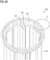
- FIG 4A illustrates an end winding arrangement 300, in accordance to the present invention, having stator bars 201 illustrated in FIG 3 .
- the end winding arrangement 300 includes multiple stator bars 201 each having a linear member 103, an involute member 301, and a cell bend member 105.
- FIG 4B illustrates an enlarged view of a portion of the end winding arrangement 300 marked "A" in FIG 4A showing connector members 302.
- Each of the connector members 302 connects the conductors 106 accommodated inside the stator bars 201 and extending out of the involute members 301.
- the connector members 302 are of a twisted configuration in form of a twisted clip structure for connecting conductors 106.
- Parts 302A and 302B of the twisted clip structures each accommodate conductors 106 there within for forming a connection there between.
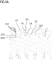
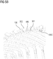
- FIGS 5A-5C illustrate various embodiments of a connector member 302 used for interconnecting conductors 106 accommodated within the involute members 301 of the end winding arrangement 300 illustrated in FIG 4A , in accordance to the present invention.
- FIG 5A illustrates a connector member 302 of a non-twisted configuration in form of a pair of linear plates 302C and 302D clamped together via one or more fasteners 302E to form a connection between the conductors 106.
- the conductors 106 are configured to have protrusions 106B in form of spherical connections, that are fastened between the linear plates 302C and 302D with help of fasteners 302E.
- FIG 5B illustrates a connector member 302 of yet another non-twisted configuration in form of a flat bar, for interconnection the conductors 106.
- the conductors 106 are configured with bent ends 106C that are connected via the connector members 302.
- FIG 5C illustrates a connector member 302 of yet another non-twisted configuration in form of a fastener 302E such as a nut-bolt arrangement for fastening the conductors 106.
- the conductors 106 are configured to form joints there between, for example, with curved ends 106D to form a lap joint or a bolted joint by having mutually cavities overlapping for accommodating the fastener 302E.
- FIG 6 illustrates a sectional view of an active part of an electric generator 600 having a rotor 602 and a stator 601 with the end winding arrangement 300, in accordance to the present invention.
- the stator 601 comprises a frame 601A, a stator core 601B partially surrounding the rotor 602, and stator bars 201.
- the stator bars 201 are rigidly attached to the stator core 601B.
- the end winding arrangement 300 shown in FIG 6 is as disclosed in the detailed description of FIGS 3-5C .
Landscapes
- Engineering & Computer Science (AREA)
- Power Engineering (AREA)
- Insulation, Fastening Of Motor, Generator Windings (AREA)
- Windings For Motors And Generators (AREA)
Abstract
Description
- The present invention relates to an end winding arrangement of a stator of an electro-mechanical device, having at least two stator bars, each stator bar comprising a linear member, an involute member, and a cell bend member.
- Such an electro-mechanical device is known to a person skilled in the art. Such a commonly known electro-mechanical device is, for example, an electric generator.
- Typically, an electric generator comprises a stator and a rotor disposed within the stator.
FIG 1 illustrates anend winding arrangement 101, in accordance to the state of the art, of a stator of an electric generator. Theend winding arrangement 101 has a plurality ofstator bars 201 interconnected byconductors 106. Each of thestator bars 201 accommodates therewithin aconductor 106. Eachstator bar 201 has alinear member 103, aninvolute member 104, and acell bend member 105.FIG 2 illustrates astator bar 102, in accordance to the state of the art, of theend winding arrangement 101 illustrated inFIG 1 . Thelinear member 103 and theinvolute member 104 are attached via thecell bend member 105. Theinvolute member 104 has aninvolute section 104A extending from thecell bend member 105, and alead bend section 104B extending from theinvolute section 104A. Theconductor 106 extends out of thelead bend section 104B. Thelead bend section 104B is disposed angularly with respect to theinvolute section 104A so as to provide ease of connection of theconductors 106 accommodated therewithin. Typically, theend winding arrangements 101, in electric generators are required for coil connections, via theseconductors 106. A large amount of material such as copper is spent for construction of theseend winding arrangements 101. Moreover, length of theinvolute members 104 of thestator bars 102, make the stator and in turn the generator longer and bulkier in size thereby, introducing vibration issues during operation of the electric generator which leads to dusting, strand breakage, etc. Furthermore, higher rewound time is required as a large quantity of auxiliary connection elements such as diamond spacers and end blocks are required for longer involutemembers 104. Furthermore, longer length of theinvolute members 104 poses design challenges in terms of not meeting electrical strikes with stator frame and creates many design complexities and manufacturing complexities due to bending of thestator bars 201. Additionally, longer length of theinvolute members 104 requires complex arrangement for mechanical support of the stator thereby increasing costs associated therewith. - Therefore, it is an object of the present invention to provide an end winding arrangement of a stator of an electro-mechanical device of the aforementioned kind, having at least two stator bars each including at least a linear member, a cell bend member, and an involute member, that reduces size of the electro-mechanical device and costs associated therewith, without compromising operational efficiency of the electro-mechanical device.
- The end winding arrangement disclosed in the present invention achieves the aforementioned object, in that each of the at least two stator bars is configured to have a unitary involute member, that is a single involute member without any lead bends, extending from the cell bend member such that an overall length of the stator bar is reduced.
- In accordance with the present invention, an end winding arrangement of a stator of an electro-mechanical device, having at least two stator bars each including at least a linear member, an involute member, and a cell bend member is provided. While the invention has been described with reference to various parts of the stator bar addressed using words such as a linear member, an involute member, and a cell bend member, it is understood that a stator bar is configured as a single piece of material and that these words, which have been used herein and after, are merely words of description to identify and illustrate various parts of the stator bar, rather than words of limitation and are in no way to be construed as limiting of the present invention disclosed herein.
- In accordance with the present invention, each of the at least two stator bars is configured to have a unitary involute member extending from the cell bend member. The unitary involute member refers to a single involute section extending from the cell bend member, for example, a member having a gradual change in its slope along its length, without a drastic change of slope such as a near orthogonal bend. Advantageously, the involute member is configured without a lead bend section as disclosed in
FIG 2 . The involute member is configured of a developed length of about 15% to about 60% of a developed length of the stator bar. Elimination of the lead bend section results in a reduction in an overall developed length of the stator bar of about 3% to about 6%. The involute member is disposed angularly with respect to a linear member of the stator bar and is attached to the linear member via the cell bend member. The involute member is cantilevered at the cell bend member such that a free end of the involute member provides an opening for conductors to extend through, for connection with conductors accommodated inside other involute members of other stator bars. - The end winding arrangement disclosed herein comprises a connector member configured to interconnect the conductor accommodated inside each of the two stator bars. Due to elimination of the lead bend section, the conductors extending out of the involute member are disposed angularly with respect to the linear member. In a preferred embodiment according to the present invention, the conductors extending out of the involute member are aligned with respect to the geospatial positioning, for example, an inclination, of the involute member. In another embodiment according to the present invention, the conductors extending out of the involute member are configured according to connection requirements, for example, the conductors of the at least two stator bars are bent towards each other in order to be fastened by a fastener.
- In order to interconnect each of the conductors, the connector member is configured to have a twisted and/or a non-twisted configuration. The twisted configuration comprises, for example, a configuration wherein two or more parts of the connector member have their planes angularly disposed with respect to one another. Connector members with twisted configurations comprise, for example, a bent clip connector member, a curved clamp connector member, etc. Advantageously, the twisted-configuration connector members avoid requirement to bend the conductors thereby, reducing complexities involved in the assembly of the end winding arrangement. The non-twisted configuration comprises, for example, a configuration wherein the parts of the connector member majorly lie in a single plane. Connector members with non-twisted configurations comprise, for example, a nut-bolt connector member, a pin connector member, a linear clamp connector member, etc. The connector member configuration is selected based on the conductor being connected, that is, a shape, a configuration, etc., of the conductor being connected. In an embodiment according to the present invention, when the conductor extending through the involute member is having a rectangular shaped flat end extending at an axial inclination nearly same as an axial inclination of the involute member, a twisted configuration of the connector member is selected for interconnection of the conductors. In another embodiment according to the present invention, when the conductor extending through the involute member is of a configuration comprising, for example, a conductor with a bent end, a conductor with a curved end, a conductor with a protruding end, etc., a non-twisted configuration of the connector member is selected.
- Also disclosed herein is a stator for an electro-mechanical device having a frame, a stator core attached to the frame, and the aforementioned end winding arrangement having at least two stator bars each having at least a linear member and a cell bend member, wherein each of the stator bars is configured to have a unitary involute member extending from the cell bend member.
- Also disclosed herein is an electro-mechanical device having a rotor and a stator including the aformentioned end winding arrangement having at least two stator bars each having at least a linear member and a cell bend member, wherein each of the stator bars is configured to have a unitary involute member extending from the cell bend member. The electromechanical device is an electric generator or an electric motor.
- The above-mentioned and other features of the invention will now be addressed with reference to the accompanying drawings of the present invention. The illustrated embodiments are intended to illustrate, but not limit the invention.
- The present invention is further described hereinafter with reference to illustrated embodiments shown in the accompanying drawings, in which:
- FIG 1
- illustrates an end winding arrangement, in accordance to the state of the art, of a stator of an electric generator.
- FIG 2
- illustrates a stator bar, in accordance to the state of the art, of the end winding arrangement illustrated in
FIG 1 . - FIG 3
- illustrates a stator bar, in accordance to the present invention, of an end winding arrangement of a stator of an electric generator.
- FIG 4A
- illustrates an end winding arrangement, in accordance to the present invention, having stator bars illustrated in
FIG 3 . - FIG 4B
- illustrates an enlarged view of a portion of the end winding arrangement marked "A" in
FIG 4A showing connector members. - FIGS 5A-5C
- illustrate various embodiments of a connector member used for interconnecting conductors accommodated within the involute members of the end winding arrangement illustrated in
FIG 4A , in accordance to the present invention. - FIG 6
- illustrates a sectional view of an active part of an electric generator having a rotor and a stator with the end winding arrangement, in accordance to the present invention.
- Various embodiments are described with reference to the drawings, wherein like reference numerals are used to refer to like elements throughout. In the following description, for the purpose of explanation, numerous specific details are set forth in order to provide thorough understanding of one or more embodiments. It may be evident that such embodiments may be practiced without these specific details.
-
FIG 3 illustrates astator bar 201, in accordance to the present invention, of an end winding arrangement of a stator of an electric generator. Thestator bar 201 comprises alinear member 103, acell bend member 105, and aninvolute member 301. Aconductor 106 is accommodated within thestator bar 201 and extends from within thelinear member 103 and out of afree end 301A of theinvolute member 301. Theinvolute member 301A and atop part 106A of theconductor 106 extending through theinvolute member 301, are aligned with respect to each other as shown in theFIG 3 . -
FIG 4A illustrates anend winding arrangement 300, in accordance to the present invention, havingstator bars 201 illustrated inFIG 3 . Theend winding arrangement 300 includesmultiple stator bars 201 each having alinear member 103, aninvolute member 301, and acell bend member 105.FIG 4B illustrates an enlarged view of a portion of theend winding arrangement 300 marked "A" inFIG 4A showingconnector members 302. Each of theconnector members 302 connects theconductors 106 accommodated inside the stator bars 201 and extending out of theinvolute members 301. As shown inFIG 4B , theconnector members 302 are of a twisted configuration in form of a twisted clip structure for connectingconductors 106.Parts conductors 106 there within for forming a connection there between. -
FIGS 5A-5C illustrate various embodiments of aconnector member 302 used for interconnectingconductors 106 accommodated within theinvolute members 301 of theend winding arrangement 300 illustrated inFIG 4A , in accordance to the present invention.FIG 5A illustrates aconnector member 302 of a non-twisted configuration in form of a pair oflinear plates more fasteners 302E to form a connection between theconductors 106. Theconductors 106 are configured to haveprotrusions 106B in form of spherical connections, that are fastened between thelinear plates fasteners 302E.FIG 5B illustrates aconnector member 302 of yet another non-twisted configuration in form of a flat bar, for interconnection theconductors 106. Theconductors 106 are configured with bent ends 106C that are connected via theconnector members 302.FIG 5C illustrates aconnector member 302 of yet another non-twisted configuration in form of afastener 302E such as a nut-bolt arrangement for fastening theconductors 106. Theconductors 106 are configured to form joints there between, for example, withcurved ends 106D to form a lap joint or a bolted joint by having mutually cavities overlapping for accommodating thefastener 302E. -
FIG 6 illustrates a sectional view of an active part of anelectric generator 600 having arotor 602 and astator 601 with theend winding arrangement 300, in accordance to the present invention. As illustrated inFIG 6 , thestator 601 comprises aframe 601A, astator core 601B partially surrounding therotor 602, and stator bars 201. The stator bars 201 are rigidly attached to thestator core 601B. Theend winding arrangement 300 shown inFIG 6 is as disclosed in the detailed description ofFIGS 3-5C . - The foregoing examples have been provided merely for the purpose of explanation and are in no way to be construed as limiting of the present invention disclosed herein. While the invention has been described with reference to various embodiments, it is understood that the words, which have been used herein, are words of description and illustration, rather than words of limitation. Further, although the invention has been described herein with reference to particular means, materials, and embodiments, the invention is not intended to be limited to the particulars disclosed herein; rather, the invention extends to all functionally equivalent structures, methods and uses, such as are within the scope of the appended claims. Those skilled in the art, having the benefit of the teachings of this specification, may affect numerous modifications thereto and changes may be made without departing from the scope and spirit of the invention in its aspects.
-
- 101 end winding arrangement (state of art)
- 102 stator bar (state of the art)
- 103 linear member of the stator bar
- 104 involute member (state of the art)
- 104A involute section of the involute member
- 104B lead bend section of the involute member
- 105 cell bend member
- 106 conductor
- 106A top part of the conductor
- 106B protrusions of the conductor/spherical connection of the conductor
- 106C bent ends of the conductor
- 106D curved ends of the conductor
- 201 stator bar
- 300 end winding arrangement
- 301 involute member
- 301A free end of involute member
- 302 connector member
- 302A, 302B parts of a connector member having twisted configuration
- 302C, 302D plates of a connector member having non-twisted configuration
- 302E fasteners of a connector member having non-twisted configuration
- 600 electro-mechanical device (electric generator)
- 601 stator
- 601A frame of the stator
- 601B stator core
Claims (10)
- An end winding arrangement (300) of a stator (601) of an electro-mechanical device (600), having:- at least two stator bars (201) each having at least a linear member (103) and a cell bend member (105);characterized in that:- each of the at least two stator bars (201) is configured to have a unitary involute member (301) extending from the cell bend member (105).
- The end winding arrangement (300) according to claim 1, wherein the involute member (301) is configured without a lead bend section (104B).
- The end winding arrangement (300) according to any one of the claims 1 and 2, wherein the involute member (301) is cantilevered at the cell bend member (105).
- The end winding arrangement (300) according to any one of the previous claims, wherein the involute member (301) is configured of a developed length of about 15% to about 60% of a developed length of the stator bar (201).
- The end winding arrangement (300) according to the claim 1, further comprises a connector member (302) configured to interconnect a conductor (106) accommodated inside each of the at least two stator bars (201).
- The end winding arrangement (300) according to the claim 5, wherein the connector member (302) is configured to have one or more of a twisted configuration and non-twisted configuration.
- The end winding arrangement (300) according to the claim 6, wherein the configuration of the connector member (302) is selected based on the conductor (106) being connected.
- A stator (601) for an electro-mechanical device (600), having:- a frame (601A);- a stator core (601B) attached to the frame (601A); and- an end winding arrangement (300) according to claims 1-7 extending from the stator core (601B).
- An electro-mechanical device (600) having:- a rotor (602); and- a stator (601) including an end winding arrangement (300), according to claim 8.
- The electromechanical device (600) according to claim 9, is one of an electric generator and an electric motor.
Priority Applications (2)
| Application Number | Priority Date | Filing Date | Title |
|---|---|---|---|
| EP18180187.9A EP3588742B1 (en) | 2018-06-27 | 2018-06-27 | End winding arrangement for an electro-mechanical device |
| US16/452,672 US11171531B2 (en) | 2018-06-27 | 2019-06-26 | End winding arrangement for an electro-mechanical device |
Applications Claiming Priority (1)
| Application Number | Priority Date | Filing Date | Title |
|---|---|---|---|
| EP18180187.9A EP3588742B1 (en) | 2018-06-27 | 2018-06-27 | End winding arrangement for an electro-mechanical device |
Publications (2)
| Publication Number | Publication Date |
|---|---|
| EP3588742A1 true EP3588742A1 (en) | 2020-01-01 |
| EP3588742B1 EP3588742B1 (en) | 2023-10-11 |
Family
ID=62814892
Family Applications (1)
| Application Number | Title | Priority Date | Filing Date |
|---|---|---|---|
| EP18180187.9A Active EP3588742B1 (en) | 2018-06-27 | 2018-06-27 | End winding arrangement for an electro-mechanical device |
Country Status (2)
| Country | Link |
|---|---|
| US (1) | US11171531B2 (en) |
| EP (1) | EP3588742B1 (en) |
Families Citing this family (1)
| Publication number | Priority date | Publication date | Assignee | Title |
|---|---|---|---|---|
| JP7505453B2 (en) * | 2021-06-22 | 2024-06-25 | トヨタ自動車株式会社 | Cooling system and stator for rotating electrical machine |
Citations (2)
| Publication number | Priority date | Publication date | Assignee | Title |
|---|---|---|---|---|
| US5789840A (en) * | 1996-02-29 | 1998-08-04 | Ge Canada Inc. | Endhead joint for stator bars |
| WO2006063186A1 (en) * | 2004-12-10 | 2006-06-15 | Siemens Power Generation, Inc. | Bolted spherical series and phase connector for stator coils of electrical generators |
Family Cites Families (3)
| Publication number | Priority date | Publication date | Assignee | Title |
|---|---|---|---|---|
| DE10215937A1 (en) * | 2002-04-11 | 2003-10-23 | Alstom Switzerland Ltd | Winding for a dynamoelectric machine |
| US8497617B2 (en) * | 2009-07-15 | 2013-07-30 | GM Global Technology Operations LLC | Stators with improved conductor assembly and method of making same |
| US8981606B2 (en) * | 2012-05-18 | 2015-03-17 | Siemens Energy, Inc. | Bolted connector for stator coils of an electrical generator |
-
2018
- 2018-06-27 EP EP18180187.9A patent/EP3588742B1/en active Active
-
2019
- 2019-06-26 US US16/452,672 patent/US11171531B2/en active Active
Patent Citations (2)
| Publication number | Priority date | Publication date | Assignee | Title |
|---|---|---|---|---|
| US5789840A (en) * | 1996-02-29 | 1998-08-04 | Ge Canada Inc. | Endhead joint for stator bars |
| WO2006063186A1 (en) * | 2004-12-10 | 2006-06-15 | Siemens Power Generation, Inc. | Bolted spherical series and phase connector for stator coils of electrical generators |
Also Published As
| Publication number | Publication date |
|---|---|
| US20200006996A1 (en) | 2020-01-02 |
| US11171531B2 (en) | 2021-11-09 |
| EP3588742B1 (en) | 2023-10-11 |
Similar Documents
| Publication | Publication Date | Title |
|---|---|---|
| RU2513899C1 (en) | Wire fastening method and wire harness | |
| US5789840A (en) | Endhead joint for stator bars | |
| US20090140585A1 (en) | Interface connector for a motor and a motor incorporating the interface connector | |
| CN101286378B (en) | cable harness | |
| JP2015039266A (en) | Vehicular cable unit | |
| US11171531B2 (en) | End winding arrangement for an electro-mechanical device | |
| CN101312309A (en) | Coil connecting structure, coil connecting method, set of conductors, and electric motor | |
| CN110892590A (en) | Electrical plug contact for high-current applications and plug connector system for high-current applications | |
| JP2019200997A (en) | Wiring assembly for equipment | |
| US20060199411A1 (en) | Windmill cable system and method | |
| US6624546B2 (en) | Radio-frequency interference suppressing choke with elongated portions for brush-type motors | |
| US20100253165A1 (en) | Phase lead connections for a bar wound stator | |
| WO2018101987A1 (en) | Conductor connector accessories and methods for connecting conductors to conductor connector accessories | |
| JP2021108534A (en) | Wiring assembly for devices | |
| JP7010802B2 (en) | Flat wiring material | |
| JP6158539B2 (en) | Electric wire branching structure | |
| JP6719873B2 (en) | Wiring assembly for vehicle equipment | |
| CN100395943C (en) | Motor, neutral wire terminal and connection method of neutral wire | |
| CN115458978A (en) | Interface components and electric drives | |
| JPH08190820A (en) | Wire terminal holder | |
| CN108899695B (en) | Wire locker, connector, motor and household appliance | |
| JP2022141994A (en) | cable unit | |
| CN113544926A (en) | busbar | |
| JP2002051426A5 (en) | ||
| CN220775254U (en) | A PTC heater outlet fixing structure for buses |
Legal Events
| Date | Code | Title | Description |
|---|---|---|---|
| PUAI | Public reference made under article 153(3) epc to a published international application that has entered the european phase |
Free format text: ORIGINAL CODE: 0009012 |
|
| STAA | Information on the status of an ep patent application or granted ep patent |
Free format text: STATUS: THE APPLICATION HAS BEEN PUBLISHED |
|
| AK | Designated contracting states |
Kind code of ref document: A1 Designated state(s): AL AT BE BG CH CY CZ DE DK EE ES FI FR GB GR HR HU IE IS IT LI LT LU LV MC MK MT NL NO PL PT RO RS SE SI SK SM TR |
|
| AX | Request for extension of the european patent |
Extension state: BA ME |
|
| STAA | Information on the status of an ep patent application or granted ep patent |
Free format text: STATUS: REQUEST FOR EXAMINATION WAS MADE |
|
| 17P | Request for examination filed |
Effective date: 20200310 |
|
| RBV | Designated contracting states (corrected) |
Designated state(s): AL AT BE BG CH CY CZ DE DK EE ES FI FR GB GR HR HU IE IS IT LI LT LU LV MC MK MT NL NO PL PT RO RS SE SI SK SM TR |
|
| STAA | Information on the status of an ep patent application or granted ep patent |
Free format text: STATUS: EXAMINATION IS IN PROGRESS |
|
| 17Q | First examination report despatched |
Effective date: 20201124 |
|
| RAP1 | Party data changed (applicant data changed or rights of an application transferred) |
Owner name: SIEMENS ENERGY GLOBAL GMBH & CO. KG |
|
| GRAP | Despatch of communication of intention to grant a patent |
Free format text: ORIGINAL CODE: EPIDOSNIGR1 |
|
| STAA | Information on the status of an ep patent application or granted ep patent |
Free format text: STATUS: GRANT OF PATENT IS INTENDED |
|
| INTG | Intention to grant announced |
Effective date: 20230531 |
|
| GRAS | Grant fee paid |
Free format text: ORIGINAL CODE: EPIDOSNIGR3 |
|
| GRAA | (expected) grant |
Free format text: ORIGINAL CODE: 0009210 |
|
| STAA | Information on the status of an ep patent application or granted ep patent |
Free format text: STATUS: THE PATENT HAS BEEN GRANTED |
|
| AK | Designated contracting states |
Kind code of ref document: B1 Designated state(s): AL AT BE BG CH CY CZ DE DK EE ES FI FR GB GR HR HU IE IS IT LI LT LU LV MC MK MT NL NO PL PT RO RS SE SI SK SM TR |
|
| REG | Reference to a national code |
Ref country code: GB Ref legal event code: FG4D |
|
| REG | Reference to a national code |
Ref country code: CH Ref legal event code: EP |
|
| REG | Reference to a national code |
Ref country code: DE Ref legal event code: R096 Ref document number: 602018059058 Country of ref document: DE |
|
| REG | Reference to a national code |
Ref country code: IE Ref legal event code: FG4D |
|
| REG | Reference to a national code |
Ref country code: LT Ref legal event code: MG9D |
|
| REG | Reference to a national code |
Ref country code: NL Ref legal event code: MP Effective date: 20231011 |
|
| REG | Reference to a national code |
Ref country code: AT Ref legal event code: MK05 Ref document number: 1621219 Country of ref document: AT Kind code of ref document: T Effective date: 20231011 |
|
| PG25 | Lapsed in a contracting state [announced via postgrant information from national office to epo] |
Ref country code: NL Free format text: LAPSE BECAUSE OF FAILURE TO SUBMIT A TRANSLATION OF THE DESCRIPTION OR TO PAY THE FEE WITHIN THE PRESCRIBED TIME-LIMIT Effective date: 20231011 |
|
| PG25 | Lapsed in a contracting state [announced via postgrant information from national office to epo] |
Ref country code: GR Free format text: LAPSE BECAUSE OF FAILURE TO SUBMIT A TRANSLATION OF THE DESCRIPTION OR TO PAY THE FEE WITHIN THE PRESCRIBED TIME-LIMIT Effective date: 20240112 |
|
| PG25 | Lapsed in a contracting state [announced via postgrant information from national office to epo] |
Ref country code: IS Free format text: LAPSE BECAUSE OF FAILURE TO SUBMIT A TRANSLATION OF THE DESCRIPTION OR TO PAY THE FEE WITHIN THE PRESCRIBED TIME-LIMIT Effective date: 20240211 |
|
| PG25 | Lapsed in a contracting state [announced via postgrant information from national office to epo] |
Ref country code: LT Free format text: LAPSE BECAUSE OF FAILURE TO SUBMIT A TRANSLATION OF THE DESCRIPTION OR TO PAY THE FEE WITHIN THE PRESCRIBED TIME-LIMIT Effective date: 20231011 |
|
| PG25 | Lapsed in a contracting state [announced via postgrant information from national office to epo] |
Ref country code: AT Free format text: LAPSE BECAUSE OF FAILURE TO SUBMIT A TRANSLATION OF THE DESCRIPTION OR TO PAY THE FEE WITHIN THE PRESCRIBED TIME-LIMIT Effective date: 20231011 |
|
| PG25 | Lapsed in a contracting state [announced via postgrant information from national office to epo] |
Ref country code: ES Free format text: LAPSE BECAUSE OF FAILURE TO SUBMIT A TRANSLATION OF THE DESCRIPTION OR TO PAY THE FEE WITHIN THE PRESCRIBED TIME-LIMIT Effective date: 20231011 |
|
| PG25 | Lapsed in a contracting state [announced via postgrant information from national office to epo] |
Ref country code: LT Free format text: LAPSE BECAUSE OF FAILURE TO SUBMIT A TRANSLATION OF THE DESCRIPTION OR TO PAY THE FEE WITHIN THE PRESCRIBED TIME-LIMIT Effective date: 20231011 Ref country code: IS Free format text: LAPSE BECAUSE OF FAILURE TO SUBMIT A TRANSLATION OF THE DESCRIPTION OR TO PAY THE FEE WITHIN THE PRESCRIBED TIME-LIMIT Effective date: 20240211 Ref country code: GR Free format text: LAPSE BECAUSE OF FAILURE TO SUBMIT A TRANSLATION OF THE DESCRIPTION OR TO PAY THE FEE WITHIN THE PRESCRIBED TIME-LIMIT Effective date: 20240112 Ref country code: ES Free format text: LAPSE BECAUSE OF FAILURE TO SUBMIT A TRANSLATION OF THE DESCRIPTION OR TO PAY THE FEE WITHIN THE PRESCRIBED TIME-LIMIT Effective date: 20231011 Ref country code: BG Free format text: LAPSE BECAUSE OF FAILURE TO SUBMIT A TRANSLATION OF THE DESCRIPTION OR TO PAY THE FEE WITHIN THE PRESCRIBED TIME-LIMIT Effective date: 20240111 Ref country code: AT Free format text: LAPSE BECAUSE OF FAILURE TO SUBMIT A TRANSLATION OF THE DESCRIPTION OR TO PAY THE FEE WITHIN THE PRESCRIBED TIME-LIMIT Effective date: 20231011 Ref country code: PT Free format text: LAPSE BECAUSE OF FAILURE TO SUBMIT A TRANSLATION OF THE DESCRIPTION OR TO PAY THE FEE WITHIN THE PRESCRIBED TIME-LIMIT Effective date: 20240212 |
|
| PG25 | Lapsed in a contracting state [announced via postgrant information from national office to epo] |
Ref country code: SE Free format text: LAPSE BECAUSE OF FAILURE TO SUBMIT A TRANSLATION OF THE DESCRIPTION OR TO PAY THE FEE WITHIN THE PRESCRIBED TIME-LIMIT Effective date: 20231011 Ref country code: RS Free format text: LAPSE BECAUSE OF FAILURE TO SUBMIT A TRANSLATION OF THE DESCRIPTION OR TO PAY THE FEE WITHIN THE PRESCRIBED TIME-LIMIT Effective date: 20231011 Ref country code: PL Free format text: LAPSE BECAUSE OF FAILURE TO SUBMIT A TRANSLATION OF THE DESCRIPTION OR TO PAY THE FEE WITHIN THE PRESCRIBED TIME-LIMIT Effective date: 20231011 Ref country code: NO Free format text: LAPSE BECAUSE OF FAILURE TO SUBMIT A TRANSLATION OF THE DESCRIPTION OR TO PAY THE FEE WITHIN THE PRESCRIBED TIME-LIMIT Effective date: 20240111 Ref country code: LV Free format text: LAPSE BECAUSE OF FAILURE TO SUBMIT A TRANSLATION OF THE DESCRIPTION OR TO PAY THE FEE WITHIN THE PRESCRIBED TIME-LIMIT Effective date: 20231011 Ref country code: HR Free format text: LAPSE BECAUSE OF FAILURE TO SUBMIT A TRANSLATION OF THE DESCRIPTION OR TO PAY THE FEE WITHIN THE PRESCRIBED TIME-LIMIT Effective date: 20231011 |
|
| PG25 | Lapsed in a contracting state [announced via postgrant information from national office to epo] |
Ref country code: DK Free format text: LAPSE BECAUSE OF FAILURE TO SUBMIT A TRANSLATION OF THE DESCRIPTION OR TO PAY THE FEE WITHIN THE PRESCRIBED TIME-LIMIT Effective date: 20231011 |
|
| REG | Reference to a national code |
Ref country code: DE Ref legal event code: R097 Ref document number: 602018059058 Country of ref document: DE |
|
| PG25 | Lapsed in a contracting state [announced via postgrant information from national office to epo] |
Ref country code: CZ Free format text: LAPSE BECAUSE OF FAILURE TO SUBMIT A TRANSLATION OF THE DESCRIPTION OR TO PAY THE FEE WITHIN THE PRESCRIBED TIME-LIMIT Effective date: 20231011 |
|
| PG25 | Lapsed in a contracting state [announced via postgrant information from national office to epo] |
Ref country code: SK Free format text: LAPSE BECAUSE OF FAILURE TO SUBMIT A TRANSLATION OF THE DESCRIPTION OR TO PAY THE FEE WITHIN THE PRESCRIBED TIME-LIMIT Effective date: 20231011 |
|
| PG25 | Lapsed in a contracting state [announced via postgrant information from national office to epo] |
Ref country code: SM Free format text: LAPSE BECAUSE OF FAILURE TO SUBMIT A TRANSLATION OF THE DESCRIPTION OR TO PAY THE FEE WITHIN THE PRESCRIBED TIME-LIMIT Effective date: 20231011 Ref country code: SK Free format text: LAPSE BECAUSE OF FAILURE TO SUBMIT A TRANSLATION OF THE DESCRIPTION OR TO PAY THE FEE WITHIN THE PRESCRIBED TIME-LIMIT Effective date: 20231011 Ref country code: RO Free format text: LAPSE BECAUSE OF FAILURE TO SUBMIT A TRANSLATION OF THE DESCRIPTION OR TO PAY THE FEE WITHIN THE PRESCRIBED TIME-LIMIT Effective date: 20231011 Ref country code: EE Free format text: LAPSE BECAUSE OF FAILURE TO SUBMIT A TRANSLATION OF THE DESCRIPTION OR TO PAY THE FEE WITHIN THE PRESCRIBED TIME-LIMIT Effective date: 20231011 Ref country code: DK Free format text: LAPSE BECAUSE OF FAILURE TO SUBMIT A TRANSLATION OF THE DESCRIPTION OR TO PAY THE FEE WITHIN THE PRESCRIBED TIME-LIMIT Effective date: 20231011 Ref country code: CZ Free format text: LAPSE BECAUSE OF FAILURE TO SUBMIT A TRANSLATION OF THE DESCRIPTION OR TO PAY THE FEE WITHIN THE PRESCRIBED TIME-LIMIT Effective date: 20231011 |
|
| PLBE | No opposition filed within time limit |
Free format text: ORIGINAL CODE: 0009261 |
|
| STAA | Information on the status of an ep patent application or granted ep patent |
Free format text: STATUS: NO OPPOSITION FILED WITHIN TIME LIMIT |
|
| 26N | No opposition filed |
Effective date: 20240712 |
|
| PG25 | Lapsed in a contracting state [announced via postgrant information from national office to epo] |
Ref country code: SI Free format text: LAPSE BECAUSE OF FAILURE TO SUBMIT A TRANSLATION OF THE DESCRIPTION OR TO PAY THE FEE WITHIN THE PRESCRIBED TIME-LIMIT Effective date: 20231011 |
|
| PG25 | Lapsed in a contracting state [announced via postgrant information from national office to epo] |
Ref country code: SI Free format text: LAPSE BECAUSE OF FAILURE TO SUBMIT A TRANSLATION OF THE DESCRIPTION OR TO PAY THE FEE WITHIN THE PRESCRIBED TIME-LIMIT Effective date: 20231011 |
|
| PG25 | Lapsed in a contracting state [announced via postgrant information from national office to epo] |
Ref country code: MC Free format text: LAPSE BECAUSE OF FAILURE TO SUBMIT A TRANSLATION OF THE DESCRIPTION OR TO PAY THE FEE WITHIN THE PRESCRIBED TIME-LIMIT Effective date: 20231011 |
|
| PG25 | Lapsed in a contracting state [announced via postgrant information from national office to epo] |
Ref country code: LU Free format text: LAPSE BECAUSE OF NON-PAYMENT OF DUE FEES Effective date: 20240627 |
|
| GBPC | Gb: european patent ceased through non-payment of renewal fee |
Effective date: 20240627 |
|
| PG25 | Lapsed in a contracting state [announced via postgrant information from national office to epo] |
Ref country code: IE Free format text: LAPSE BECAUSE OF NON-PAYMENT OF DUE FEES Effective date: 20240627 |
|
| PG25 | Lapsed in a contracting state [announced via postgrant information from national office to epo] |
Ref country code: BE Free format text: LAPSE BECAUSE OF NON-PAYMENT OF DUE FEES Effective date: 20240630 |
|
| PG25 | Lapsed in a contracting state [announced via postgrant information from national office to epo] |
Ref country code: GB Free format text: LAPSE BECAUSE OF NON-PAYMENT OF DUE FEES Effective date: 20240627 |
|
| REG | Reference to a national code |
Ref country code: BE Ref legal event code: MM Effective date: 20240630 |
|
| PGFP | Annual fee paid to national office [announced via postgrant information from national office to epo] |
Ref country code: DE Payment date: 20250626 Year of fee payment: 8 |
|
| PGFP | Annual fee paid to national office [announced via postgrant information from national office to epo] |
Ref country code: FR Payment date: 20250624 Year of fee payment: 8 |
|
| PG25 | Lapsed in a contracting state [announced via postgrant information from national office to epo] |
Ref country code: FI Free format text: LAPSE BECAUSE OF FAILURE TO SUBMIT A TRANSLATION OF THE DESCRIPTION OR TO PAY THE FEE WITHIN THE PRESCRIBED TIME-LIMIT Effective date: 20231011 |
|
| PGFP | Annual fee paid to national office [announced via postgrant information from national office to epo] |
Ref country code: IT Payment date: 20250623 Year of fee payment: 8 |
|
| PGFP | Annual fee paid to national office [announced via postgrant information from national office to epo] |
Ref country code: CH Payment date: 20250701 Year of fee payment: 8 |
|
| PG25 | Lapsed in a contracting state [announced via postgrant information from national office to epo] |
Ref country code: CY Free format text: LAPSE BECAUSE OF FAILURE TO SUBMIT A TRANSLATION OF THE DESCRIPTION OR TO PAY THE FEE WITHIN THE PRESCRIBED TIME-LIMIT; INVALID AB INITIO Effective date: 20180627 |
|
| PG25 | Lapsed in a contracting state [announced via postgrant information from national office to epo] |
Ref country code: HU Free format text: LAPSE BECAUSE OF FAILURE TO SUBMIT A TRANSLATION OF THE DESCRIPTION OR TO PAY THE FEE WITHIN THE PRESCRIBED TIME-LIMIT; INVALID AB INITIO Effective date: 20180627 |