EP3588712A1 - A copper conductor - Google Patents
A copper conductor Download PDFInfo
- Publication number
- EP3588712A1 EP3588712A1 EP18179797.8A EP18179797A EP3588712A1 EP 3588712 A1 EP3588712 A1 EP 3588712A1 EP 18179797 A EP18179797 A EP 18179797A EP 3588712 A1 EP3588712 A1 EP 3588712A1
- Authority
- EP
- European Patent Office
- Prior art keywords
- copper conductor
- longitudinal axis
- conductor according
- ridges
- copper
- Prior art date
- Legal status (The legal status is an assumption and is not a legal conclusion. Google has not performed a legal analysis and makes no representation as to the accuracy of the status listed.)
- Granted
Links
Images



Classifications
-
- H—ELECTRICITY
- H02—GENERATION; CONVERSION OR DISTRIBUTION OF ELECTRIC POWER
- H02G—INSTALLATION OF ELECTRIC CABLES OR LINES, OR OF COMBINED OPTICAL AND ELECTRIC CABLES OR LINES
- H02G5/00—Installations of bus-bars
- H02G5/10—Cooling
-
- H—ELECTRICITY
- H01—ELECTRIC ELEMENTS
- H01B—CABLES; CONDUCTORS; INSULATORS; SELECTION OF MATERIALS FOR THEIR CONDUCTIVE, INSULATING OR DIELECTRIC PROPERTIES
- H01B5/00—Non-insulated conductors or conductive bodies characterised by their form
-
- H—ELECTRICITY
- H01—ELECTRIC ELEMENTS
- H01B—CABLES; CONDUCTORS; INSULATORS; SELECTION OF MATERIALS FOR THEIR CONDUCTIVE, INSULATING OR DIELECTRIC PROPERTIES
- H01B5/00—Non-insulated conductors or conductive bodies characterised by their form
- H01B5/02—Single bars, rods, wires, or strips
-
- H—ELECTRICITY
- H01—ELECTRIC ELEMENTS
- H01F—MAGNETS; INDUCTANCES; TRANSFORMERS; SELECTION OF MATERIALS FOR THEIR MAGNETIC PROPERTIES
- H01F27/00—Details of transformers or inductances, in general
- H01F27/28—Coils; Windings; Conductive connections
Definitions
- the present invention relates to a copper conductor.
- Medium voltage (MV) switching gear uses copper bars as conductors, such as busbars. These are usually made as flat profiles, e.g. 80mm x 10mm, that are cut to the length needed. For high currents, multiples of two, three or more flat profiles can be used. For the highest currents, D shaped profiles have been used. The dimension and size of the cross section of the conductor is usually chosen to fit the limits of conductor temperature, or temperature rise, when maximal rated current is passed through. Cylinder shaped conductors for ring core transformers, such as KOKS type transformers, also have dimensions chosen in a similar manner. Such arrangements have limitations of performance and cost.
- a copper conductor comprising:
- the at least one body comprises connection means at a first position of the longitudinal axis and comprises connection means at a second position of the longitudinal axis.
- connection means at a first position of the longitudinal axis and comprises connection means at a second position of the longitudinal axis.
- the at least one body comprises cooling means.
- the conductivity and cooling of a system such as a medium voltage switchgear is improved.
- the skin effect is taken into account to improve conductivity, with more copper being placed at positions of highest current density in the system such as busbars of switchgear operating in a three-phase arrangement.
- the body of the conductor having cooling means provides for improved cooling, leading to reduced temperatures through improved convection cooling, and even improved radiative cooling.
- the at least one body comprises at least one substantially planar sub-body.
- sheet copper metal can be used to form the conductor further leading to cost benefits.
- the at least one body comprises at least one arcuate sub-body extending from the at least one substantially planar sub-body.
- the copper conductor such as a busbar can have a "D" profile, and sheet metal can be bent to form the conductor.
- the at least one body is one body and wherein the cooling means comprises a plurality of ridges.
- a plurality of ridges is used to increase the conductor surface area and lead to improved cooling through improved convective cooling and improved radiative cooling.
- the plurality of ridges extend in the direction of the longitudinal axis.
- At least two of the plurality of ridges are substantially parallel one to the other.
- the plurality of ridges are substantially parallel to each other.
- the plurality of ridges are formed on the at least one substantially planar sub-body.
- the cooling means comprises a plurality of ventilation holes through the at least one body.
- convective air cooling is improved and the overall surface area is additionally increased leading to improved radiative cooling as well as to improved convective cooling.
- the at least body comprises a plurality of bodies.
- the overall area of the cooling surfaces having ventilation holes can be significantly increased leading to improved cooling, whilst maintaining a required cross sectional area, and at the same time minimizing the amount of copper required.
- the plurality of ventilation holes through the at least one body comprises at least one ventilation hole through a first body of the plurality of bodies and comprises at least one ventilation hole through a second body of the plurality of bodies.
- the at least one ventilation hole through the first body is substantially aligned with the at least one ventilation hole through the second body.
- the plurality of ventilation holes through the at least one body comprises a plurality of ventilation holes through the first body and comprises a plurality of ventilation holes through the second body.
- the plurality of ventilation holes through the first body are substantially aligned with the plurality of ventilation holes through the second body.
- first and second connection means are mounting holes.
- a medium voltage switchgear comprising at least one copper conductor according to the first aspect.
- a copper conductor for a ring core transformer comprising a hollow core extending along a longitudinal axis of the conductor surrounded by an inner surface of the copper conductor.
- a cross section of the conductor perpendicular to the longitudinal axis at a position along the longitudinal axis has an outer perimeter of an outer surface of the copper conductor and has an inner perimeter of the inner surface of the copper conductor surrounding the hollow core, and wherein a total length of the outer perimeter is less than a total length of the inner perimeter.
- the inner surface of the copper conductor comprises a plurality of ridges extending in the direction of the longitudinal axis.
- a ring core transformer comprising a copper conductor according to the third aspect.
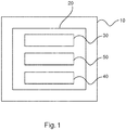
- Fig. 1 shows an example of a copper conductor 10 for a medium voltage switchgear.
- the copper conductor 10 comprises at least one body 20 extending in a longitudinal axis.
- the at least one body 20 comprises connection means 30 at a first position of the longitudinal axis.
- the at least one body also comprises connection means 40 at a second position of the longitudinal axis.
- the at least one body comprises cooling means 50.
- the copper conductor is a busbar, of for example a medium voltage switchgear.
- the at least one body comprises at least one substantially planar sub-body.
- the at least one body comprises at least one arcuate sub-body extending from the at least one substantially planar sub-body.
- the at least one body is one body and wherein the cooling means comprises a plurality of ridges.
- the plurality of ridges extend in the direction of the longitudinal axis.
- At least two of the plurality of ridges are substantially parallel one to the other.
- the plurality of ridges are substantially parallel to each other.
- the plurality of ridges are formed on the at least one substantially planar sub-body.
- the cooling means comprises a plurality of ventilation holes through the at least one body.
- the ventilation holes are circular.
- the ventilation holes are slots.
- the at least body comprises a plurality of bodies.
- the plurality of ventilation holes through the at least one body comprises at least one ventilation hole through a first body of the plurality of bodies and comprises at least one ventilation hole through a second body of the plurality of bodies.
- the at least one ventilation hole through the first body can be substantially aligned with the at least one ventilation hole through the second body.
- the ventilation holes are offset one from the other.
- the plurality of ventilation holes through the at least one body comprises a plurality of ventilation holes through the first body and comprises a plurality of ventilation holes through the second body.
- the plurality of ventilation holes through the first body can substantially aligned with the plurality of ventilation holes through the second body.
- the ventilation holes are offset one from the other.
- the first and second connection means are mounting holes.
- the copper conductor as described with respect to Fig. 1 can be used in a medium voltage switchgear, for example for the busbars.
- a medium voltage switchgear (not shown) comprising at least one copper conductor as described with respect to Fig. 1 .
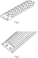
- Fig. 2 shows an example of a copper conductor suitable for use in a medium voltage switchgear, for example as a busbar.
- the copper conductor has connection means at both ends, in form of two adjacent holes. Only the connection means at one end are shown in Fig. 2 .
- the copper conductor is formed from sheet metal, and cooling means in the form of circular ventilation holes have been punched through the copper sheet.
- the copper sheet has then been bent on two sides to form two arcuate sides extending from a planar section, and as such forms a D profile.
- the holes punched through the copper sheet can be different sizes and be at higher or lower separation from one another with respect to that shown in Fig. 2 .
- the holes can also be cut through the sheet, rather than being punched through, and can be shapes other than the circles shown, such as squares, slots or any other suitable shape that is punched or cut through the sheet.
- Fig. 3 shows an example of a copper conductor suitable for use in a medium voltage switchgear, for example as a busbar.
- the copper conductor has connection means at both ends, in form of two adjacent holes. Only the connection means at one end are shown in Fig. 3 .
- the copper conductor has a solid profile and has cooling means in the form of a number of ridges (or grooves) extending along the length (longitudinal axis of the conductor). The number of ridges, their spacing from one another, their height, and width can be different to that shown in Fig. 3 .
- Fig. 4 shows an example of a copper conductor suitable for use in a medium voltage switchgear, for example as a busbar.
- the copper conductor has connection means at both ends, in form of two adjacent holes. Only the connection means at one end are shown in Fig. 4 .
- the copper conductor is formed from sheet metal, and cooling means in the form of clotted ventilation holes have been punched through the copper sheet.
- the copper conductor is similar to that shown in Fig. 2 , and could have circular ventilation holes or other shaped holes. Also, in this case the copper sheet has then been bent such that a D shape is again formed, but the end sections now form a planar part rather than the central section as for Fig. 2 .
- the holes can be formed as described with respect to Fig. 2 .
- Fig. 5 shows an example of a copper conductor suitable for use in a medium voltage switchgear, for example as a busbar.
- the copper conductor has connection means at both ends, in form of two adjacent holes. Only the connection means at one end are shown in Fig. 4 .
- the copper conductor has a solid profile and has cooling means in the form of a number of ridges (or grooves) extending along the length (longitudinal axis of the conductor), in a similar manner to that shown in Fig. 3 .
- the conductor also has a number of ventilation holes, which in this example are slots, but can be circular holes or holes of any suitable shape.
- Figs. 6 and 7 show examples of copper conductors suitable for use in a medium voltage switchgear, for example as a busbar.
- Each copper conductor has a number (two and three for Fig. 6 and Fig. 7 respectively) of separate elements (sub-body) as shown for Fig. 2 , but that are stacked within each other.
- Each has connection means at both ends, in form of two adjacent holes thereby enabling the whole assembly to be securely mounted within the switchgear. Only the connection means at one end are shown.
- cooling means in the form of ventilation holes have been punched through each individual element of the and in these examples, the holes have been punched into each element such that they line up when assembled together.
- cooling means has been used for a copper conductor, useable for example with a MV switchgear.
- This principle has also been used for a copper conductor for a ring core transformer, as exemplified in Figs 8 and 9 .
- the cylindrical shaped conductor can be used in a ring-core transformed, such as a KOKS transformer (not shown), and the cooling means has been applied by making the core of the conductor hollow.
- the conductor comprises a hollow core extending along a longitudinal axis of the conductor surrounded by an inner surface of the copper conductor.
- the inner surface of the copper conductor comprises a plurality of ridges extending in the direction of the longitudinal axis.
- a cross section of the conductor perpendicular to the longitudinal axis at a position along the longitudinal axis has an outer perimeter of an outer surface of the copper conductor and has an inner perimeter of the inner surface of the copper conductor surrounding the hollow core.
- a total length of the outer perimeter is less than a total length of the inner perimeter.
- the inner surface of the cylindrical conductor surrounding the hollow core has a piecewise continuous circular cross section, and the available surface area to improve cooling has been further increased by providing the inner surface of the conductor with ridges running down the inside of the conductor as shown in Fig. 9 .
- a circular cross section conductor is shown in Figs. 8-9 , however the described principles apply for other cross sections, such as elliptical.
- a ring core transformer has a copper conductor as described with respect to any of Figs. 8-9 .
Landscapes
- Engineering & Computer Science (AREA)
- Power Engineering (AREA)
- Patch Boards (AREA)
- Installation Of Bus-Bars (AREA)
Abstract
Description
- The present invention relates to a copper conductor.
- Medium voltage (MV) switching gear uses copper bars as conductors, such as busbars. These are usually made as flat profiles, e.g. 80mm x 10mm, that are cut to the length needed. For high currents, multiples of two, three or more flat profiles can be used. For the highest currents, D shaped profiles have been used. The dimension and size of the cross section of the conductor is usually chosen to fit the limits of conductor temperature, or temperature rise, when maximal rated current is passed through. Cylinder shaped conductors for ring core transformers, such as KOKS type transformers, also have dimensions chosen in a similar manner. Such arrangements have limitations of performance and cost.
- Therefore, it would be advantageous to have an improved conductor for MV switchgear and an improved conductor for ring core transformers.
- The object of the present invention is solved with the subject matter of the independent claims, wherein further embodiments are incorporated in the dependent claims.
- In a first aspect, there is provided a copper conductor, the copper conductor comprising:
- at least one body extending in a longitudinal axis.
- The at least one body comprises connection means at a first position of the longitudinal axis and comprises connection means at a second position of the longitudinal axis. Along at least a part of the longitudinal axis between the first position and the second position of the at least one body, the at least one body comprises cooling means.
- In this manner, the conductivity and cooling of a system such as a medium voltage switchgear is improved. The skin effect is taken into account to improve conductivity, with more copper being placed at positions of highest current density in the system such as busbars of switchgear operating in a three-phase arrangement. The body of the conductor having cooling means provides for improved cooling, leading to reduced temperatures through improved convection cooling, and even improved radiative cooling.
- In this way, the total amount of copper used in the conductor can be decreased leading to cost savings.
- In an example, the at least one body comprises at least one substantially planar sub-body.
- In this manner, sheet copper metal can be used to form the conductor further leading to cost benefits.
- In an example, the at least one body comprises at least one arcuate sub-body extending from the at least one substantially planar sub-body.
- In other words, the copper conductor such as a busbar can have a "D" profile, and sheet metal can be bent to form the conductor.
- In an example, the at least one body is one body and wherein the cooling means comprises a plurality of ridges.
- Thus, a plurality of ridges, with grooves between the ridges, is used to increase the conductor surface area and lead to improved cooling through improved convective cooling and improved radiative cooling.
- In an example, the plurality of ridges extend in the direction of the longitudinal axis.
- In an example, at least two of the plurality of ridges are substantially parallel one to the other.
- In an example, the plurality of ridges are substantially parallel to each other.
- In an example, the plurality of ridges are formed on the at least one substantially planar sub-body.
- In an example, the cooling means comprises a plurality of ventilation holes through the at least one body.
- Thus, convective air cooling is improved and the overall surface area is additionally increased leading to improved radiative cooling as well as to improved convective cooling.
- In an example, the at least body comprises a plurality of bodies.
- By forming a conductor from a number of bodies the overall area of the cooling surfaces having ventilation holes can be significantly increased leading to improved cooling, whilst maintaining a required cross sectional area, and at the same time minimizing the amount of copper required.
- In an example, the plurality of ventilation holes through the at least one body comprises at least one ventilation hole through a first body of the plurality of bodies and comprises at least one ventilation hole through a second body of the plurality of bodies. The at least one ventilation hole through the first body is substantially aligned with the at least one ventilation hole through the second body.
- In an example, the plurality of ventilation holes through the at least one body comprises a plurality of ventilation holes through the first body and comprises a plurality of ventilation holes through the second body. The plurality of ventilation holes through the first body are substantially aligned with the plurality of ventilation holes through the second body.
- By aligning the ventilation holes in this manner, air convective cooling is improved because air can more efficiently flow through the structure extracting heat.
- In an example, the first and second connection means are mounting holes.
- In a second aspect, there is provided a medium voltage switchgear comprising at least one copper conductor according to the first aspect.
- In a third aspect, there is provided a copper conductor for a ring core transformer. The conductor comprises a hollow core extending along a longitudinal axis of the conductor surrounded by an inner surface of the copper conductor.
- Thus, cooling is provided leading to reduced temperatures, and a reduced amount of copper can be utilized also saving costs.
- In an example, a cross section of the conductor perpendicular to the longitudinal axis at a position along the longitudinal axis has an outer perimeter of an outer surface of the copper conductor and has an inner perimeter of the inner surface of the copper conductor surrounding the hollow core, and wherein a total length of the outer perimeter is less than a total length of the inner perimeter.
- In an example, the inner surface of the copper conductor comprises a plurality of ridges extending in the direction of the longitudinal axis.
- In a fourth aspect, there is provided a ring core transformer comprising a copper conductor according to the third aspect.
- The above aspects and examples will become apparent from and be elucidated with reference to the embodiments described hereinafter.
- Exemplary embodiments will be described in the following with reference to the following drawings:
-
Fig. 1 shows a schematic representation of an example of a copper conductor for a medium voltage switchgear; -
Fig. 2 shows an example of a copper conductor for a medium voltage switchgear; -
Fig. 3 shows an example of a copper conductor for a medium voltage switchgear; -
Fig. 4 shows an example of a copper conductor for a medium voltage switchgear; -
Fig. 5 shows an example of a copper conductor for a medium voltage switchgear; -
Fig. 6 shows an example of a copper conductor for a medium voltage switchgear; -
Fig. 7 shows an example of a copper conductor for a medium voltage switchgear; -
Fig. 8 shows an example of a copper conductor for a ring core transformer; and -
Fig. 9 shows an example of a copper conductor for a ring core transformer. -
Fig. 1 shows an example of acopper conductor 10 for a medium voltage switchgear. Thecopper conductor 10 comprises at least onebody 20 extending in a longitudinal axis. The at least onebody 20 comprises connection means 30 at a first position of the longitudinal axis. The at least one body also comprises connection means 40 at a second position of the longitudinal axis. Along at least a part of the longitudinal axis between the first position and the second position of the at least one body, the at least one body comprises cooling means 50. - In an example, the copper conductor is a busbar, of for example a medium voltage switchgear.
- According to an example, the at least one body comprises at least one substantially planar sub-body.
- According to an example, the at least one body comprises at least one arcuate sub-body extending from the at least one substantially planar sub-body.
- According to an example, the at least one body is one body and wherein the cooling means comprises a plurality of ridges.
- According to an example, the plurality of ridges extend in the direction of the longitudinal axis.
- According to an example, at least two of the plurality of ridges are substantially parallel one to the other.
- According to an example, the plurality of ridges are substantially parallel to each other.
- According to an example, the plurality of ridges are formed on the at least one substantially planar sub-body.
- According to an example, the cooling means comprises a plurality of ventilation holes through the at least one body.
- In an example, the ventilation holes are circular.
- In an example, the ventilation holes are slots.
- According to an example, the at least body comprises a plurality of bodies.
- In an example, a combination of copper conductors with aluminium coolers is provided.
- According to an example, the plurality of ventilation holes through the at least one body comprises at least one ventilation hole through a first body of the plurality of bodies and comprises at least one ventilation hole through a second body of the plurality of bodies. In this example, the at least one ventilation hole through the first body can be substantially aligned with the at least one ventilation hole through the second body. However, in other examples the ventilation holes are offset one from the other.
- According to an example, the plurality of ventilation holes through the at least one body comprises a plurality of ventilation holes through the first body and comprises a plurality of ventilation holes through the second body. In this example, the plurality of ventilation holes through the first body can substantially aligned with the plurality of ventilation holes through the second body. However, in other examples the ventilation holes are offset one from the other.
- According to an example, the first and second connection means are mounting holes.
- The copper conductor as described with respect to
Fig. 1 can be used in a medium voltage switchgear, for example for the busbars. Thus, in an example there is provided a medium voltage switchgear (not shown) comprising at least one copper conductor as described with respect toFig. 1 . - The copper conductor described above with respect to
Fig. 1 is now described in more detail with reference toFigs 2-7 . -
Fig. 2 shows an example of a copper conductor suitable for use in a medium voltage switchgear, for example as a busbar. The copper conductor has connection means at both ends, in form of two adjacent holes. Only the connection means at one end are shown inFig. 2 . The copper conductor is formed from sheet metal, and cooling means in the form of circular ventilation holes have been punched through the copper sheet. The copper sheet has then been bent on two sides to form two arcuate sides extending from a planar section, and as such forms a D profile. The holes punched through the copper sheet can be different sizes and be at higher or lower separation from one another with respect to that shown inFig. 2 . The holes can also be cut through the sheet, rather than being punched through, and can be shapes other than the circles shown, such as squares, slots or any other suitable shape that is punched or cut through the sheet. -
Fig. 3 shows an example of a copper conductor suitable for use in a medium voltage switchgear, for example as a busbar. The copper conductor has connection means at both ends, in form of two adjacent holes. Only the connection means at one end are shown inFig. 3 . The copper conductor has a solid profile and has cooling means in the form of a number of ridges (or grooves) extending along the length (longitudinal axis of the conductor). The number of ridges, their spacing from one another, their height, and width can be different to that shown inFig. 3 . -
Fig. 4 shows an example of a copper conductor suitable for use in a medium voltage switchgear, for example as a busbar. The copper conductor has connection means at both ends, in form of two adjacent holes. Only the connection means at one end are shown inFig. 4 . The copper conductor is formed from sheet metal, and cooling means in the form of clotted ventilation holes have been punched through the copper sheet. The copper conductor is similar to that shown inFig. 2 , and could have circular ventilation holes or other shaped holes. Also, in this case the copper sheet has then been bent such that a D shape is again formed, but the end sections now form a planar part rather than the central section as forFig. 2 . The holes can be formed as described with respect toFig. 2 . -
Fig. 5 shows an example of a copper conductor suitable for use in a medium voltage switchgear, for example as a busbar. The copper conductor has connection means at both ends, in form of two adjacent holes. Only the connection means at one end are shown inFig. 4 . The copper conductor has a solid profile and has cooling means in the form of a number of ridges (or grooves) extending along the length (longitudinal axis of the conductor), in a similar manner to that shown inFig. 3 . However, to augment the cooling effect from the ridges the conductor also has a number of ventilation holes, which in this example are slots, but can be circular holes or holes of any suitable shape. -
Figs. 6 and7 show examples of copper conductors suitable for use in a medium voltage switchgear, for example as a busbar. Each copper conductor has a number (two and three forFig. 6 andFig. 7 respectively) of separate elements (sub-body) as shown forFig. 2 , but that are stacked within each other. Each has connection means at both ends, in form of two adjacent holes thereby enabling the whole assembly to be securely mounted within the switchgear. Only the connection means at one end are shown. As shown inFig. 2 , cooling means in the form of ventilation holes have been punched through each individual element of the and in these examples, the holes have been punched into each element such that they line up when assembled together. - As described above, cooling means has been used for a copper conductor, useable for example with a MV switchgear. This principle has also been used for a copper conductor for a ring core transformer, as exemplified in
Figs 8 and 9 . The cylindrical shaped conductor can be used in a ring-core transformed, such as a KOKS transformer (not shown), and the cooling means has been applied by making the core of the conductor hollow. - Thus, in an example of the copper conductor for a ring core transformer, the conductor comprises a hollow core extending along a longitudinal axis of the conductor surrounded by an inner surface of the copper conductor.
- In an example of the copper conductor for a ring core transformer the inner surface of the copper conductor comprises a plurality of ridges extending in the direction of the longitudinal axis.
- In another example of the copper conductor for a ring core transformer a cross section of the conductor perpendicular to the longitudinal axis at a position along the longitudinal axis has an outer perimeter of an outer surface of the copper conductor and has an inner perimeter of the inner surface of the copper conductor surrounding the hollow core. A total length of the outer perimeter is less than a total length of the inner perimeter.
- In further detail, in
Fig. 8 the inner surface of the cylindrical conductor surrounding the hollow core has a piecewise continuous circular cross section, and the available surface area to improve cooling has been further increased by providing the inner surface of the conductor with ridges running down the inside of the conductor as shown inFig. 9 . A circular cross section conductor is shown inFigs. 8-9 , however the described principles apply for other cross sections, such as elliptical. - In an example, a ring core transformer has a copper conductor as described with respect to any of
Figs. 8-9 . - While the invention has been illustrated and described in detail in the drawings and foregoing description, such illustration and description are to be considered illustrative or exemplary and not restrictive. The invention is not limited to the disclosed embodiments. Other variations to the disclosed embodiments can be understood and effected by those skilled in the art in practicing a claimed invention, from a study of the drawings, the disclosure, and the dependent claims.
- In the claims, the word "comprising" does not exclude other elements or steps, and the indefinite article "a" or "an" does not exclude a plurality. A single processor or other unit may fulfill the functions of several items re-cited in the claims. The mere fact that certain measures are re-cited in mutually different dependent claims does not indicate that a combination of these measures cannot be used to advantage. Any reference signs in the claims should not be construed as limiting the scope.
Claims (18)
- A copper conductor (10) for a medium voltage switchgear, the copper conductor comprising:- at least one body (20) extending in a longitudinal axis;wherein, the at least one body comprises connection means (30) at a first position of the longitudinal axis and comprises connection means (40) at a second position of the longitudinal axis; and
wherein, along at least a part of the longitudinal axis between the first position and the second position of the at least one body, the at least one body comprises cooling means (50). - Copper conductor according to claim 1, wherein the at least one body comprises at least one substantially planar sub-body.
- Copper conductor according to claim 2, wherein the at least one body comprises at least one arcuate sub-body extending from the at least one substantially planar sub-body.
- Copper conductor according to any of claims 1-3, wherein the at least one body is one body and wherein the cooling means comprises a plurality of ridges.
- Copper conductor according to claim 4, wherein the plurality of ridges extend in the direction of the longitudinal axis.
- Copper conductor according to any of claims 4-5, wherein at least two of the plurality of ridges are substantially parallel one to the other.
- Copper conductor according to any of claims 4-6, wherein the plurality of ridges are substantially parallel to each other.
- Copper conductor according to any of claims 2-7, wherein the plurality of ridges are formed on the at least one substantially planar sub-body.
- Copper conductor according to any of claims 1-8, wherein the cooling means comprises a plurality of ventilation holes through the at least one body.
- Copper conductor according to claim 9 when dependent on any of claims 1-3, wherein the at least body comprises a plurality of bodies.
- Copper conductor according to claim 10, wherein the plurality of ventilation holes through the at least one body comprises at least one ventilation hole through a first body of the plurality of bodies and comprises at least one ventilation hole through a second body of the plurality of bodies, and wherein the at least one ventilation hole through the first body is substantially aligned with the at least one ventilation hole through the second body.
- Copper conductor according to claim 11, wherein the plurality of ventilation holes through the at least one body comprises a plurality of ventilation holes through the first body and comprises a plurality of ventilation holes through the second body, and wherein the plurality of ventilation holes through the first body are substantially aligned with the plurality of ventilation holes through the second body.
- Copper conductor according to any of claims 1-12, wherein the first and second connection means are mounting holes.
- A medium voltage switchgear comprising at least one copper conductor according to any of claims 1-13.
- A copper conductor for a ring core transformer, wherein the conductor comprises a hollow core extending along a longitudinal axis of the conductor surrounded by an inner surface of the copper conductor.
- Copper conductor according to claim 15, wherein a cross section of the conductor perpendicular to the longitudinal axis at a position along the longitudinal axis has an outer perimeter of an outer surface of the copper conductor and has an inner perimeter of the inner surface of the copper conductor surrounding the hollow core, and wherein a total length of the outer perimeter is less than a total length of the inner perimeter.
- Copper conductor according to any of claims 15-16, wherein the inner surface of the copper conductor comprises a plurality of ridges extending in the direction of the longitudinal axis.
- A ring core transformer comprising a copper conductor according to any of claims 15-17.
Priority Applications (3)
| Application Number | Priority Date | Filing Date | Title |
|---|---|---|---|
| EP18179797.8A EP3588712B1 (en) | 2018-06-26 | 2018-06-26 | A copper conductor |
| CN201910555147.XA CN110648782B (en) | 2018-06-26 | 2019-06-25 | Copper conductor |
| CN202210498604.8A CN114822917B (en) | 2018-06-26 | 2019-06-25 | Copper conductor |
Applications Claiming Priority (1)
| Application Number | Priority Date | Filing Date | Title |
|---|---|---|---|
| EP18179797.8A EP3588712B1 (en) | 2018-06-26 | 2018-06-26 | A copper conductor |
Publications (2)
| Publication Number | Publication Date |
|---|---|
| EP3588712A1 true EP3588712A1 (en) | 2020-01-01 |
| EP3588712B1 EP3588712B1 (en) | 2023-03-08 |
Family
ID=62814816
Family Applications (1)
| Application Number | Title | Priority Date | Filing Date |
|---|---|---|---|
| EP18179797.8A Active EP3588712B1 (en) | 2018-06-26 | 2018-06-26 | A copper conductor |
Country Status (2)
| Country | Link |
|---|---|
| EP (1) | EP3588712B1 (en) |
| CN (2) | CN110648782B (en) |
Cited By (1)
| Publication number | Priority date | Publication date | Assignee | Title |
|---|---|---|---|---|
| US12548991B2 (en) | 2021-01-29 | 2026-02-10 | Scania Cv Ab | Busbar and a vehicle comprising such a busbar |
Citations (4)
| Publication number | Priority date | Publication date | Assignee | Title |
|---|---|---|---|---|
| US2964586A (en) * | 1956-11-09 | 1960-12-13 | Isaac D Sillman | Apparatus for transmission of electricity |
| DE102012008550A1 (en) * | 2011-05-27 | 2012-11-29 | Sew-Eurodrive Gmbh & Co. Kg | Busbar portion used in converter arrangement for three-phase motor, has cooling structure for supplying air to busbar |
| WO2015042927A1 (en) * | 2013-09-29 | 2015-04-02 | Abb Technology Ltd | Main bus-bar, branch bus-bar, transfer connector and bus-bar assembly |
| CN204496946U (en) * | 2015-04-02 | 2015-07-22 | 烟台佳恒铜业有限公司 | A kind of efficient from radiating copper bus |
Family Cites Families (12)
| Publication number | Priority date | Publication date | Assignee | Title |
|---|---|---|---|---|
| SE510196C2 (en) * | 1996-03-28 | 1999-04-26 | Asea Brown Boveri | Gas insulated semiconductor valve assembly with annular electrostatic shields |
| JP4139122B2 (en) * | 2002-03-29 | 2008-08-27 | Tdk株式会社 | Method for manufacturing mixed conductor multilayer element and mixed conductor multilayer element |
| WO2006108445A1 (en) * | 2005-04-14 | 2006-10-19 | Fci Electrique France | Connecting device for electrically connecting at least three electrical conductors, and kit comprising such devices |
| CN201075310Y (en) * | 2007-09-13 | 2008-06-18 | 西安盟创电器有限公司 | Mechanical tube-shaped bus bar |
| CN101944400A (en) * | 2009-07-07 | 2011-01-12 | 王锐 | Hollow conductor with star-shaped section |
| JP5775785B2 (en) * | 2011-10-06 | 2015-09-09 | 株式会社フジクラ | Oxide superconducting wire and method for producing the same |
| CN203520902U (en) * | 2013-10-17 | 2014-04-02 | 崔宝林 | Tubular bus with inner and outer circles in different shapes |
| EP2894744A1 (en) * | 2014-01-14 | 2015-07-15 | Siemens Aktiengesellschaft | Method of optimizing cooling efficiency in tubular bus structures |
| CN204947525U (en) * | 2015-09-26 | 2016-01-06 | 江苏向荣电气有限公司 | A kind of compact height heat radiation bus duct |
| JP6720840B2 (en) * | 2016-11-16 | 2020-07-08 | 富士電機株式会社 | Cooling structure for winding parts |
| CN106655035A (en) * | 2016-12-28 | 2017-05-10 | 汉舟四川铜铝复合科技有限公司 | Copper aluminum interface alloy composite conductor internal wave tube used in tubular bus duct |
| CN207303399U (en) * | 2017-09-22 | 2018-05-01 | 昆山恩能聚新能源科技有限公司 | A kind of heat radiating type copper bar is flexible coupling |
-
2018
- 2018-06-26 EP EP18179797.8A patent/EP3588712B1/en active Active
-
2019
- 2019-06-25 CN CN201910555147.XA patent/CN110648782B/en active Active
- 2019-06-25 CN CN202210498604.8A patent/CN114822917B/en active Active
Patent Citations (4)
| Publication number | Priority date | Publication date | Assignee | Title |
|---|---|---|---|---|
| US2964586A (en) * | 1956-11-09 | 1960-12-13 | Isaac D Sillman | Apparatus for transmission of electricity |
| DE102012008550A1 (en) * | 2011-05-27 | 2012-11-29 | Sew-Eurodrive Gmbh & Co. Kg | Busbar portion used in converter arrangement for three-phase motor, has cooling structure for supplying air to busbar |
| WO2015042927A1 (en) * | 2013-09-29 | 2015-04-02 | Abb Technology Ltd | Main bus-bar, branch bus-bar, transfer connector and bus-bar assembly |
| CN204496946U (en) * | 2015-04-02 | 2015-07-22 | 烟台佳恒铜业有限公司 | A kind of efficient from radiating copper bus |
Cited By (1)
| Publication number | Priority date | Publication date | Assignee | Title |
|---|---|---|---|---|
| US12548991B2 (en) | 2021-01-29 | 2026-02-10 | Scania Cv Ab | Busbar and a vehicle comprising such a busbar |
Also Published As
| Publication number | Publication date |
|---|---|
| CN114822917A (en) | 2022-07-29 |
| EP3588712B1 (en) | 2023-03-08 |
| CN110648782A (en) | 2020-01-03 |
| CN114822917B (en) | 2024-04-09 |
| CN110648782B (en) | 2022-04-29 |
Similar Documents
| Publication | Publication Date | Title |
|---|---|---|
| KR20120099673A (en) | Winding arrangement for an inductive component | |
| US20200044422A1 (en) | System comprising a bus bar device and a power converter housing, and method for the production thereof, power converter for a vehicle, and vehicle | |
| US10027076B2 (en) | Current carrying systems and methods of assembling the same | |
| US20140342585A1 (en) | Bus bar for electrical power distribution | |
| CA2390335C (en) | Electrical machine with a winding | |
| CN103531273A (en) | Special-shaped transposed conductor | |
| EP3588712A1 (en) | A copper conductor | |
| EP2621062A1 (en) | Connecting device | |
| KR101717797B1 (en) | Electric conductor with improved cooling and electric appliance in a sealed housing comprising at least one such conductor | |
| CN109313983B (en) | Power capacitor module with cooling arrangement | |
| EP3018667B1 (en) | Cooling ducts for transformers' winding | |
| CN111989834B (en) | Assemblies for connecting circuit breakers to conductive layers of laminated busbars and switchgear comprising such assemblies | |
| CN105051853A (en) | Gas cooler for a medium voltage switchgear assembly | |
| CN121241408A (en) | Rectangular tubular conductor bus with solid core and internal heat dissipation structure | |
| CN109346296A (en) | Transformer | |
| KR20110084831A (en) | Electrical conductors in a gas-insulated circuit | |
| WO2020225132A1 (en) | An electrical machine comprising a cooling device | |
| US12315676B2 (en) | Capacitor with electrically conductive cooling channel | |
| CN101501960A (en) | Stator of a turbo generator | |
| US12062478B2 (en) | Electrical device having heat generating components with improved heat removal using turbulent flow | |
| JP5088879B2 (en) | Distribution board | |
| BRPI0610194B1 (en) | PROTECTIVE SYSTEM FOR ON-LINE BUSHING OF AN ELECTRICAL INSTALLATION AND CONNECTION ELEMENT TO HOLD AND FIX WALL ELEMENTS | |
| EP3671985A1 (en) | Compartment for a medium voltage gas insulated switchgear | |
| JP5514656B2 (en) | High voltage equipment | |
| CN113056862B (en) | Multi-layer neutral bus |
Legal Events
| Date | Code | Title | Description |
|---|---|---|---|
| PUAI | Public reference made under article 153(3) epc to a published international application that has entered the european phase |
Free format text: ORIGINAL CODE: 0009012 |
|
| STAA | Information on the status of an ep patent application or granted ep patent |
Free format text: STATUS: THE APPLICATION HAS BEEN PUBLISHED |
|
| AK | Designated contracting states |
Kind code of ref document: A1 Designated state(s): AL AT BE BG CH CY CZ DE DK EE ES FI FR GB GR HR HU IE IS IT LI LT LU LV MC MK MT NL NO PL PT RO RS SE SI SK SM TR |
|
| AX | Request for extension of the european patent |
Extension state: BA ME |
|
| STAA | Information on the status of an ep patent application or granted ep patent |
Free format text: STATUS: REQUEST FOR EXAMINATION WAS MADE |
|
| 17P | Request for examination filed |
Effective date: 20200527 |
|
| RBV | Designated contracting states (corrected) |
Designated state(s): AL AT BE BG CH CY CZ DE DK EE ES FI FR GB GR HR HU IE IS IT LI LT LU LV MC MK MT NL NO PL PT RO RS SE SI SK SM TR |
|
| STAA | Information on the status of an ep patent application or granted ep patent |
Free format text: STATUS: EXAMINATION IS IN PROGRESS |
|
| 17Q | First examination report despatched |
Effective date: 20210602 |
|
| GRAP | Despatch of communication of intention to grant a patent |
Free format text: ORIGINAL CODE: EPIDOSNIGR1 |
|
| STAA | Information on the status of an ep patent application or granted ep patent |
Free format text: STATUS: GRANT OF PATENT IS INTENDED |
|
| INTG | Intention to grant announced |
Effective date: 20221018 |
|
| GRAS | Grant fee paid |
Free format text: ORIGINAL CODE: EPIDOSNIGR3 |
|
| GRAA | (expected) grant |
Free format text: ORIGINAL CODE: 0009210 |
|
| STAA | Information on the status of an ep patent application or granted ep patent |
Free format text: STATUS: THE PATENT HAS BEEN GRANTED |
|
| RIN1 | Information on inventor provided before grant (corrected) |
Inventor name: PERNICA, ROMAN Inventor name: KALINA, EMIL Inventor name: HEMEK, PAVEL Inventor name: SKUCI, MICHAL Inventor name: BIHARY, JOZEF |
|
| AK | Designated contracting states |
Kind code of ref document: B1 Designated state(s): AL AT BE BG CH CY CZ DE DK EE ES FI FR GB GR HR HU IE IS IT LI LT LU LV MC MK MT NL NO PL PT RO RS SE SI SK SM TR |
|
| RAP3 | Party data changed (applicant data changed or rights of an application transferred) |
Owner name: ABB SCHWEIZ AG |
|
| REG | Reference to a national code |
Ref country code: CH Ref legal event code: EP Ref country code: AT Ref legal event code: REF Ref document number: 1553232 Country of ref document: AT Kind code of ref document: T Effective date: 20230315 |
|
| REG | Reference to a national code |
Ref country code: IE Ref legal event code: FG4D |
|
| REG | Reference to a national code |
Ref country code: DE Ref legal event code: R096 Ref document number: 602018046884 Country of ref document: DE |
|
| REG | Reference to a national code |
Ref country code: LT Ref legal event code: MG9D |
|
| REG | Reference to a national code |
Ref country code: NL Ref legal event code: MP Effective date: 20230308 |
|
| PG25 | Lapsed in a contracting state [announced via postgrant information from national office to epo] |
Ref country code: RS Free format text: LAPSE BECAUSE OF FAILURE TO SUBMIT A TRANSLATION OF THE DESCRIPTION OR TO PAY THE FEE WITHIN THE PRESCRIBED TIME-LIMIT Effective date: 20230308 Ref country code: NO Free format text: LAPSE BECAUSE OF FAILURE TO SUBMIT A TRANSLATION OF THE DESCRIPTION OR TO PAY THE FEE WITHIN THE PRESCRIBED TIME-LIMIT Effective date: 20230608 Ref country code: LV Free format text: LAPSE BECAUSE OF FAILURE TO SUBMIT A TRANSLATION OF THE DESCRIPTION OR TO PAY THE FEE WITHIN THE PRESCRIBED TIME-LIMIT Effective date: 20230308 Ref country code: LT Free format text: LAPSE BECAUSE OF FAILURE TO SUBMIT A TRANSLATION OF THE DESCRIPTION OR TO PAY THE FEE WITHIN THE PRESCRIBED TIME-LIMIT Effective date: 20230308 Ref country code: HR Free format text: LAPSE BECAUSE OF FAILURE TO SUBMIT A TRANSLATION OF THE DESCRIPTION OR TO PAY THE FEE WITHIN THE PRESCRIBED TIME-LIMIT Effective date: 20230308 Ref country code: ES Free format text: LAPSE BECAUSE OF FAILURE TO SUBMIT A TRANSLATION OF THE DESCRIPTION OR TO PAY THE FEE WITHIN THE PRESCRIBED TIME-LIMIT Effective date: 20230308 |
|
| REG | Reference to a national code |
Ref country code: AT Ref legal event code: MK05 Ref document number: 1553232 Country of ref document: AT Kind code of ref document: T Effective date: 20230308 |
|
| PG25 | Lapsed in a contracting state [announced via postgrant information from national office to epo] |
Ref country code: SE Free format text: LAPSE BECAUSE OF FAILURE TO SUBMIT A TRANSLATION OF THE DESCRIPTION OR TO PAY THE FEE WITHIN THE PRESCRIBED TIME-LIMIT Effective date: 20230308 Ref country code: NL Free format text: LAPSE BECAUSE OF FAILURE TO SUBMIT A TRANSLATION OF THE DESCRIPTION OR TO PAY THE FEE WITHIN THE PRESCRIBED TIME-LIMIT Effective date: 20230308 Ref country code: GR Free format text: LAPSE BECAUSE OF FAILURE TO SUBMIT A TRANSLATION OF THE DESCRIPTION OR TO PAY THE FEE WITHIN THE PRESCRIBED TIME-LIMIT Effective date: 20230609 Ref country code: FI Free format text: LAPSE BECAUSE OF FAILURE TO SUBMIT A TRANSLATION OF THE DESCRIPTION OR TO PAY THE FEE WITHIN THE PRESCRIBED TIME-LIMIT Effective date: 20230308 |
|
| PG25 | Lapsed in a contracting state [announced via postgrant information from national office to epo] |
Ref country code: SM Free format text: LAPSE BECAUSE OF FAILURE TO SUBMIT A TRANSLATION OF THE DESCRIPTION OR TO PAY THE FEE WITHIN THE PRESCRIBED TIME-LIMIT Effective date: 20230308 Ref country code: RO Free format text: LAPSE BECAUSE OF FAILURE TO SUBMIT A TRANSLATION OF THE DESCRIPTION OR TO PAY THE FEE WITHIN THE PRESCRIBED TIME-LIMIT Effective date: 20230308 Ref country code: PT Free format text: LAPSE BECAUSE OF FAILURE TO SUBMIT A TRANSLATION OF THE DESCRIPTION OR TO PAY THE FEE WITHIN THE PRESCRIBED TIME-LIMIT Effective date: 20230710 Ref country code: EE Free format text: LAPSE BECAUSE OF FAILURE TO SUBMIT A TRANSLATION OF THE DESCRIPTION OR TO PAY THE FEE WITHIN THE PRESCRIBED TIME-LIMIT Effective date: 20230308 Ref country code: CZ Free format text: LAPSE BECAUSE OF FAILURE TO SUBMIT A TRANSLATION OF THE DESCRIPTION OR TO PAY THE FEE WITHIN THE PRESCRIBED TIME-LIMIT Effective date: 20230308 Ref country code: AT Free format text: LAPSE BECAUSE OF FAILURE TO SUBMIT A TRANSLATION OF THE DESCRIPTION OR TO PAY THE FEE WITHIN THE PRESCRIBED TIME-LIMIT Effective date: 20230308 |
|
| PG25 | Lapsed in a contracting state [announced via postgrant information from national office to epo] |
Ref country code: SK Free format text: LAPSE BECAUSE OF FAILURE TO SUBMIT A TRANSLATION OF THE DESCRIPTION OR TO PAY THE FEE WITHIN THE PRESCRIBED TIME-LIMIT Effective date: 20230308 Ref country code: PL Free format text: LAPSE BECAUSE OF FAILURE TO SUBMIT A TRANSLATION OF THE DESCRIPTION OR TO PAY THE FEE WITHIN THE PRESCRIBED TIME-LIMIT Effective date: 20230308 Ref country code: IS Free format text: LAPSE BECAUSE OF FAILURE TO SUBMIT A TRANSLATION OF THE DESCRIPTION OR TO PAY THE FEE WITHIN THE PRESCRIBED TIME-LIMIT Effective date: 20230708 |
|
| REG | Reference to a national code |
Ref country code: DE Ref legal event code: R097 Ref document number: 602018046884 Country of ref document: DE |
|
| PLBE | No opposition filed within time limit |
Free format text: ORIGINAL CODE: 0009261 |
|
| STAA | Information on the status of an ep patent application or granted ep patent |
Free format text: STATUS: NO OPPOSITION FILED WITHIN TIME LIMIT |
|
| PG25 | Lapsed in a contracting state [announced via postgrant information from national office to epo] |
Ref country code: MC Free format text: LAPSE BECAUSE OF FAILURE TO SUBMIT A TRANSLATION OF THE DESCRIPTION OR TO PAY THE FEE WITHIN THE PRESCRIBED TIME-LIMIT Effective date: 20230308 |
|
| PG25 | Lapsed in a contracting state [announced via postgrant information from national office to epo] |
Ref country code: SI Free format text: LAPSE BECAUSE OF FAILURE TO SUBMIT A TRANSLATION OF THE DESCRIPTION OR TO PAY THE FEE WITHIN THE PRESCRIBED TIME-LIMIT Effective date: 20230308 Ref country code: MC Free format text: LAPSE BECAUSE OF FAILURE TO SUBMIT A TRANSLATION OF THE DESCRIPTION OR TO PAY THE FEE WITHIN THE PRESCRIBED TIME-LIMIT Effective date: 20230308 Ref country code: DK Free format text: LAPSE BECAUSE OF FAILURE TO SUBMIT A TRANSLATION OF THE DESCRIPTION OR TO PAY THE FEE WITHIN THE PRESCRIBED TIME-LIMIT Effective date: 20230308 |
|
| REG | Reference to a national code |
Ref country code: CH Ref legal event code: PL |
|
| 26N | No opposition filed |
Effective date: 20231211 |
|
| REG | Reference to a national code |
Ref country code: BE Ref legal event code: MM Effective date: 20230630 |
|
| GBPC | Gb: european patent ceased through non-payment of renewal fee |
Effective date: 20230626 |
|
| PG25 | Lapsed in a contracting state [announced via postgrant information from national office to epo] |
Ref country code: LU Free format text: LAPSE BECAUSE OF NON-PAYMENT OF DUE FEES Effective date: 20230626 |
|
| REG | Reference to a national code |
Ref country code: IE Ref legal event code: MM4A |
|
| PG25 | Lapsed in a contracting state [announced via postgrant information from national office to epo] |
Ref country code: LU Free format text: LAPSE BECAUSE OF NON-PAYMENT OF DUE FEES Effective date: 20230626 |
|
| PG25 | Lapsed in a contracting state [announced via postgrant information from national office to epo] |
Ref country code: IE Free format text: LAPSE BECAUSE OF NON-PAYMENT OF DUE FEES Effective date: 20230626 |
|
| PG25 | Lapsed in a contracting state [announced via postgrant information from national office to epo] |
Ref country code: IE Free format text: LAPSE BECAUSE OF NON-PAYMENT OF DUE FEES Effective date: 20230626 Ref country code: GB Free format text: LAPSE BECAUSE OF NON-PAYMENT OF DUE FEES Effective date: 20230626 Ref country code: CH Free format text: LAPSE BECAUSE OF NON-PAYMENT OF DUE FEES Effective date: 20230630 |
|
| PG25 | Lapsed in a contracting state [announced via postgrant information from national office to epo] |
Ref country code: BE Free format text: LAPSE BECAUSE OF NON-PAYMENT OF DUE FEES Effective date: 20230630 |
|
| PG25 | Lapsed in a contracting state [announced via postgrant information from national office to epo] |
Ref country code: BG Free format text: LAPSE BECAUSE OF FAILURE TO SUBMIT A TRANSLATION OF THE DESCRIPTION OR TO PAY THE FEE WITHIN THE PRESCRIBED TIME-LIMIT Effective date: 20230308 |
|
| PG25 | Lapsed in a contracting state [announced via postgrant information from national office to epo] |
Ref country code: BG Free format text: LAPSE BECAUSE OF FAILURE TO SUBMIT A TRANSLATION OF THE DESCRIPTION OR TO PAY THE FEE WITHIN THE PRESCRIBED TIME-LIMIT Effective date: 20230308 |
|
| PGFP | Annual fee paid to national office [announced via postgrant information from national office to epo] |
Ref country code: DE Payment date: 20250618 Year of fee payment: 8 |
|
| PGFP | Annual fee paid to national office [announced via postgrant information from national office to epo] |
Ref country code: FR Payment date: 20250626 Year of fee payment: 8 |
|
| PG25 | Lapsed in a contracting state [announced via postgrant information from national office to epo] |
Ref country code: CY Free format text: LAPSE BECAUSE OF FAILURE TO SUBMIT A TRANSLATION OF THE DESCRIPTION OR TO PAY THE FEE WITHIN THE PRESCRIBED TIME-LIMIT; INVALID AB INITIO Effective date: 20180626 |
|
| PG25 | Lapsed in a contracting state [announced via postgrant information from national office to epo] |
Ref country code: HU Free format text: LAPSE BECAUSE OF FAILURE TO SUBMIT A TRANSLATION OF THE DESCRIPTION OR TO PAY THE FEE WITHIN THE PRESCRIBED TIME-LIMIT; INVALID AB INITIO Effective date: 20180626 |
|
| PGFP | Annual fee paid to national office [announced via postgrant information from national office to epo] |
Ref country code: IT Payment date: 20250624 Year of fee payment: 8 |
|
| PG25 | Lapsed in a contracting state [announced via postgrant information from national office to epo] |
Ref country code: TR Free format text: LAPSE BECAUSE OF FAILURE TO SUBMIT A TRANSLATION OF THE DESCRIPTION OR TO PAY THE FEE WITHIN THE PRESCRIBED TIME-LIMIT Effective date: 20230308 |