EP3588692A1 - Electronic device, interface and method for operating an interface - Google Patents
Electronic device, interface and method for operating an interface Download PDFInfo
- Publication number
- EP3588692A1 EP3588692A1 EP18179860.4A EP18179860A EP3588692A1 EP 3588692 A1 EP3588692 A1 EP 3588692A1 EP 18179860 A EP18179860 A EP 18179860A EP 3588692 A1 EP3588692 A1 EP 3588692A1
- Authority
- EP
- European Patent Office
- Prior art keywords
- interface
- connector
- detachable connector
- electronic device
- detecting
- Prior art date
- Legal status (The legal status is an assumption and is not a legal conclusion. Google has not performed a legal analysis and makes no representation as to the accuracy of the status listed.)
- Withdrawn
Links
Images


Classifications
-
- H—ELECTRICITY
- H01—ELECTRIC ELEMENTS
- H01R—ELECTRICALLY-CONDUCTIVE CONNECTIONS; STRUCTURAL ASSOCIATIONS OF A PLURALITY OF MUTUALLY-INSULATED ELECTRICAL CONNECTING ELEMENTS; COUPLING DEVICES; CURRENT COLLECTORS
- H01R13/00—Details of coupling devices of the kinds covered by groups H01R12/70 or H01R24/00 - H01R33/00
- H01R13/62—Means for facilitating engagement or disengagement of coupling parts or for holding them in engagement
- H01R13/639—Additional means for holding or locking coupling parts together, after engagement, e.g. separate keylock, retainer strap
-
- H—ELECTRICITY
- H01—ELECTRIC ELEMENTS
- H01R—ELECTRICALLY-CONDUCTIVE CONNECTIONS; STRUCTURAL ASSOCIATIONS OF A PLURALITY OF MUTUALLY-INSULATED ELECTRICAL CONNECTING ELEMENTS; COUPLING DEVICES; CURRENT COLLECTORS
- H01R13/00—Details of coupling devices of the kinds covered by groups H01R12/70 or H01R24/00 - H01R33/00
- H01R13/62—Means for facilitating engagement or disengagement of coupling parts or for holding them in engagement
- H01R13/639—Additional means for holding or locking coupling parts together, after engagement, e.g. separate keylock, retainer strap
- H01R13/6397—Additional means for holding or locking coupling parts together, after engagement, e.g. separate keylock, retainer strap with means for preventing unauthorised use
-
- G—PHYSICS
- G06—COMPUTING OR CALCULATING; COUNTING
- G06F—ELECTRIC DIGITAL DATA PROCESSING
- G06F13/00—Interconnection of, or transfer of information or other signals between, memories, input/output devices or central processing units
- G06F13/38—Information transfer, e.g. on bus
- G06F13/40—Bus structure
- G06F13/4063—Device-to-bus coupling
- G06F13/409—Mechanical coupling
-
- H—ELECTRICITY
- H01—ELECTRIC ELEMENTS
- H01R—ELECTRICALLY-CONDUCTIVE CONNECTIONS; STRUCTURAL ASSOCIATIONS OF A PLURALITY OF MUTUALLY-INSULATED ELECTRICAL CONNECTING ELEMENTS; COUPLING DEVICES; CURRENT COLLECTORS
- H01R43/00—Apparatus or processes specially adapted for manufacturing, assembling, maintaining, or repairing of line connectors or current collectors or for joining electric conductors
- H01R43/26—Apparatus or processes specially adapted for manufacturing, assembling, maintaining, or repairing of line connectors or current collectors or for joining electric conductors for engaging or disengaging the two parts of a coupling device
-
- H—ELECTRICITY
- H01—ELECTRIC ELEMENTS
- H01R—ELECTRICALLY-CONDUCTIVE CONNECTIONS; STRUCTURAL ASSOCIATIONS OF A PLURALITY OF MUTUALLY-INSULATED ELECTRICAL CONNECTING ELEMENTS; COUPLING DEVICES; CURRENT COLLECTORS
- H01R2201/00—Connectors or connections adapted for particular applications
- H01R2201/06—Connectors or connections adapted for particular applications for computer periphery
Definitions
- the present disclosure relates to an electronic device, to an interface and to a method for operating an interface.
- Electronic devices such as laptop computers, multi-media set-top boxes, television sets and the like are provided with interfaces to enable interconnection between devices, receipt of signals, etc.
- the interfaces comprises physical connectors of various types and configurations.
- a connector socket defined according to the interface, is often mounted on the electronic device so that a corresponding detachable connector plug, attached to a cable or memory device for example, may be engaged with the socket connector as required to provide a link to the device.
- Some types of interface connector plug include mechanical securing mechanisms to prevent unwanted disengagement of the detachable connector plug from a connector socket.
- a plug connector on a coaxial cable may be provided with a locking nut designed to be manually rotated to engage with corresponding lugs provided on a coaxial socket connector.
- a Video Graphics Array (VGA) plug connector may incorporate securing bolts to engage with corresponding threaded nuts provided on a VGA socket connector.
- an electronic device having an interface comprising:
- An electronic device as disclosed herein is thereby able to rely upon an interface connection remaining engaged during what may be a critical transfer of data, or a real-time receipt or transmission of signals.
- Security of connection no longer relies upon a user operating a manual securing mechanism of a connector.
- Such mechanical securing mechanisms can be difficult to operate, especially in confined situations, or when an appropriate tool is not to hand. They often therefore remain unused, leaving a detachable connector susceptible to disengagement from a corresponding connector of an electronic device.
- the interface comprises at least one of: an interface for communication of digital data; an interface for communication of analogue signals; an electrical interface for the transfer of electrical power; an optical interface for communication of optical signals; an interface to a memory device; an interface to a network; and a transmission line for conveying radio frequency signals.
- the techniques disclosed herein may be applied to any type of detachable connector o secure an engagement of that connector during use.
- the electronic device is arranged to detect a use or an intended use of the interface comprising detecting a signal at the interface.
- the signal to be detected may be different for each type of interface, as would be apparent to a person of ordinary skill in the relevant art aware that the signal selected for detection is a signal likely to be indicative of a use or an intended use of the interface.
- the electronic device is arranged to detect a use or an intended use of the interface comprising: detecting a user input indicative of a use or an intended use of the interface; or detecting an activation or an intended activation of a scheduled event involving a use or an intended use of the interface.
- the electronic device may provide an interface selector switch or it may include functionality to provide, for example, a user interface enabling a user to select a particular interface for use, e.g. an input for signals.
- a user may enter scheduling information to trigger an event at a future time, such as a video recording of a broadcast programme, and to specify an input through which the broadcast programme is to be received.
- the electronic device may identify the interface in use or intended for use and may activate the associated locking mechanism to secure a respective connection for the duration of the use or intended use.
- the locking mechanism comprises a controllable actuator arranged to move at least one securing member configured to engage with or to disengage from a said detachable connector thereby to prevent or to enable, respectively, disengagement of the said detachable connector from the interface connector.
- the electronic device comprises:
- a method for operating an interface comprising:
- the method comprises:
- the detecting of a use or an intended use comprises at least one of: detecting an activation of the interface; detecting a signal at the interface; detecting a user input indicative of a use or an intended use of the interface; detecting an activation or an intended activation of a scheduled event involving a use or an intended use of the interface.
- the interface is one of a plurality of interfaces each comprising an interface connector configured according to the respective interface for engaging with a corresponding detachable connector, and a locking mechanism controllable to secure an engagement of a said detachable connector with the interface connector, the method comprising:
- an interface comprising:
- Such an interface as disclosed herein may be provided as a stand-alone item to be installed in an electronic device, having the facility to secure a detachable connector when engaged with a connector of the interface.
- the interface comprises at least one of: an interface for communication of digital data; an interface for communication of analogue signals; an electrical interface for the transfer of electrical power; an optical interface for communication of optical signals; an interface to a memory device; an interface to a network; and a transmission line for conveying radio frequency signals.
- the controller is configured to control the locking mechanism to maintain a secured engagement of the said detachable connector with the interface connector during the detected use or intended use of the interface and to enable disengagement of a said detachable connector if there is no detected use or intended use of the interface.
- the controller is configured to detect a use or an intended use comprising at least one of: detecting a signal at the interface; detecting a user input indicative of a use or an intended use of the interface; detecting an activation or an intended activation of a scheduled event involving a use or an intended use of the interface.
- the locking mechanism comprises a controllable actuator arranged to move at least one securing member configured to engage with or to disengage from a said detachable connector thereby to prevent or to enable, respectively, disengagement of the said detachable connector from the interface connector.
- Electronic devices are commonly provided with various interfaces having associated physical connectors to enable input and output of signals, data and power. Such interfaces may enable an interconnection of one electronic device with other electronic device or enable an input or output of signals from or to an antenna, for example.
- a television may be provided with a co-axial transmission line connector for receiving broadcast or closed circuit television signals and a variety of other connector types for the input and output of digital data and analogue signals.
- any disengagement of a connector through which such data or signals are being transferred may incur data or signal loss and consequential inconvenience.
- Software updates may, for example, leave a device in an unstable state if the associated data transfer is interrupted when a connector becomes disengaged.
- An interruption due to disengagement of a connector may have health and safety implications, for example if displaying real-time images, video or data that is being relied upon by a viewer to perform a safety-critical task.
- Examples of the different types of interface provided in electronic devices include: a Universal Serial Bus (USB) interface; a High Definition Multi-media Interface (HDMI); a Video Graphics Array (VGA) interface; a Digital Visual Interface (DVI); a DisplayPort interface; a phono socket; an aerial socket or other transmission line connector; and an optical interface.
- USB Universal Serial Bus
- HDMI High Definition Multi-media Interface
- VGA Video Graphics Array
- DVI Digital Visual Interface
- DisplayPort interface a phono socket
- an aerial socket or other transmission line connector and an optical interface.
- an interface connector provided in fixed association with the electronic device, for example a connector socket mounted in a housing of the electronic device, may be arranged to engage with a corresponding detachable connector plug, according to the application of the respective interface.
- a television 5 is provided with three connector sockets 10, 15, 20 accessible at a lower edge of a casing of the television 5.
- the connector sockets 10, 15, 20 are configured according to respective interface standards to receive and engage with corresponding detachable connectors 25, 30, 35 respectively, to enable connection to external devices and signal sources, as appropriate.
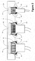
- each connector socket arrangement 50, 55, 60 may be used to replace the connector sockets 10, 15, 20 shown in Figure 1 of the television 5.
- Each connector socket arrangement 50, 55, 60 includes a locking mechanism comprising a respective pair of arms 65, 70, 75.
- Each arm has an end portion 80, 85, 90 made for example using a resilient high-friction material for use in gripping a respective detachable connector 95, 100, 105.
- the locking mechanism of the connector socket arrangement 50, 55, 60 also comprises an actuator 110, 115, 120 arranged to move the respective pair of arms 65, 70, 75.
- Each actuator 110, 115, 120 is controllable to move the respective pair of arms 65, 70, 75 between a first position, as shown in Figure 2 for the connector socket arrangements 50, 55, and a second position, as shown in Figure 2 for the socket arrangement 60.
- the end portions 80, 85, 90 of the arms 65, 70, 75 are separated from a detachable connector 95, 100, 105 when engaged with the respective connector 50, 55, 60, enabling the detachable connector 95, 100, 105 to be engaged with and disengaged from the respective connector socket 50, 55, 60 without resistance.
- the end portions 80, 85, 90 are pressed against a respective detachable connector 95, 100, 105 when engaged with the respective connector socket 50, 55, 60 to grip the detachable connector 95, 100, 105 and so prevent its disengagement from the connector socket arrangement 50, 55, 60.
- the locking mechanism may be configured so that when a power supply to the electronic device switched off, any of the arms 65, 70, 75 that are in the second position are released so that any detachable connector 95, 100, 105 that is engaged with one of the connector sockets 50, 55, 60 may be disengaged without resistance.
- the locking mechanism may be implemented as a feature of one or more of the connector socket arrangements 50, 55, 60, and therefore as a feature of the respective interface itself.
- the locking mechanism may be implemented as a feature of the electronic device, mounted for example in an external casing of the electronic device.
- mechanical arrangements using movable mechanical components different from the arrangement of arms 65, 70, 75 and actuators 110, 115, 120 shown in Figure 2 may be provided for securing the engagement of a detachable connector 95, 100, 105.
- Such mechanical components may include sliding or pivoting mechanical components arranged either to grip a detachable connector 95, 100, 105 or to lock the connector 95, 100, 105 in position by engaging with a recess other corresponding feature provided in the detachable connector 95, 100, 105, when it is engaged with the connector socket arrangement 50, 55, 60.
- Each actuator 110, 115, 120 may comprise for example an electric motor or an electromagnet to move the arms 65, 70, 75 or other mechanical components to secure the detachable connector 95, 100, 105.
- a controller may be included to control the actuators 110, 115, 120.
- the controller may be implemented as a feature of one or more connector socket arrangements 50, 55, 60, and therefore as a feature of the interface itself.
- a controller may be implemented as a feature of an electronic device comprising the respective interfaces, for example as additional functionality of a processor provided in the television 5.
- An example of the functionality implemented by the controller will now be described with reference to Figure 3 . In that example, it is assumed that the electronic device is provided with more than one interface and that the controller is provided to control locking mechanisms of any one or more of the connector socket arrangements 50, 55, 60 of the provided interfaces.
- the controller is arranged, at 130, to detect for each interface provided on the electronic device 5 whether the interface is in use or is intended to be used.
- the controller may achieve this in a number of different ways.
- the controller may be arranged to detect a signal at the respective connector socket arrangement 50, 55, 60 of the interface indicative of an active use of the interface.
- the signal may be a signal originating from within the electronic device 5 or it may be a signal originating with another electronic device via a detachable connector 95, 100, 105.
- the controller may detect a user input to the electronic device indicative of a use or an intended use of a particular interface.
- the controller may be arranged to identify the particular interface intended to receive the selected input. Similarly, the controller may be arranged to detect, for each interface, whether the interface is not in use or is not intended to be used.
- the controller activates the locking mechanism, in particular the actuator 110, 115, 120, and secures a respective detachable connector 95, 100, 105 engaged with the respective interface connector socket arrangement 50, 55, 60.
- the controller releases a respective detachable connector 95, 100, 105 engaged with each interface connector socket arrangement 50, 55, 60 that the controller detects as not being used or not intended for use. The controller then repeats the process to detect any changes of use or intended use and to act upon any such change.
- the controller may, for example, be arranged to ensure, if there is a loss of power to the electronic device 5 or if the electronic device 5 is switched off or put into a standby mode, that all detachable connectors 95, 100, 105 currently engaged with connector sockets 50, 55, 60 provided in or associated with the electronic device are released so that they may be disengaged if required without resistance.
- the controller referred to herein may in practice be provided by a single chip or integrated circuit or plural chips or integrated circuits, optionally provided as a chipset, an application-specific integrated circuit (ASIC), field-programmable gate array (FPGA), digital signal processor (DSP), graphics processing units (GPUs), etc.
- the chip or chips may comprise circuitry (as well as possibly firmware) for embodying at least one or more of a data processor or processors, a digital signal processor or processors, baseband circuitry and radio frequency circuitry, which are configurable so as to operate in accordance with the exemplary embodiments.
- the exemplary embodiments may be implemented at least in part by computer software stored in (non-transitory) memory and executable by the processor, or by hardware, or by a combination of tangibly stored software and hardware (and tangibly stored firmware).
- the invention also extends to computer programs, particularly computer programs on or in a carrier, adapted for putting the invention into practice.
- the program may be in the form of non-transitory source code, object code, a code intermediate source and object code such as in partially compiled form, or in any other non-transitory form suitable for use in the implementation of processes according to the invention.
- the carrier may be any entity or device capable of carrying the program.
- the carrier may comprise a storage medium, such as a solid-state drive (SSD) or other semiconductor-based RAM; a ROM, for example a CD ROM or a semiconductor ROM; a magnetic recording medium, for example a floppy disk or hard disk; optical memory devices in general; etc.
- SSD solid-state drive
- ROM read-only memory
- magnetic recording medium for example a floppy disk or hard disk
- optical memory devices in general etc.
Landscapes
- Engineering & Computer Science (AREA)
- General Engineering & Computer Science (AREA)
- Theoretical Computer Science (AREA)
- Manufacturing & Machinery (AREA)
- Computer Hardware Design (AREA)
- Physics & Mathematics (AREA)
- General Physics & Mathematics (AREA)
- Computer Security & Cryptography (AREA)
- Details Of Connecting Devices For Male And Female Coupling (AREA)
Abstract
Description
- The present disclosure relates to an electronic device, to an interface and to a method for operating an interface.
- Electronic devices such as laptop computers, multi-media set-top boxes, television sets and the like are provided with interfaces to enable interconnection between devices, receipt of signals, etc. The interfaces comprises physical connectors of various types and configurations. A connector socket, defined according to the interface, is often mounted on the electronic device so that a corresponding detachable connector plug, attached to a cable or memory device for example, may be engaged with the socket connector as required to provide a link to the device.
- Some types of interface connector plug include mechanical securing mechanisms to prevent unwanted disengagement of the detachable connector plug from a connector socket. For example, a plug connector on a coaxial cable may be provided with a locking nut designed to be manually rotated to engage with corresponding lugs provided on a coaxial socket connector. A Video Graphics Array (VGA) plug connector may incorporate securing bolts to engage with corresponding threaded nuts provided on a VGA socket connector.
- According to a first aspect disclosed herein, there is provided an electronic device having an interface, the electronic device comprising:
- an interface connector, configured according to the interface for engaging with a corresponding detachable connector; and
- a locking mechanism controllable to secure an engagement of a said detachable connector with the interface connector,
- wherein the electronic device is configured to detect a use or an intended use of the interface and to activate the locking mechanism to secure an engagement of a said detachable connector with the interface connector.
- An electronic device as disclosed herein is thereby able to rely upon an interface connection remaining engaged during what may be a critical transfer of data, or a real-time receipt or transmission of signals. Security of connection no longer relies upon a user operating a manual securing mechanism of a connector. Such mechanical securing mechanisms can be difficult to operate, especially in confined situations, or when an appropriate tool is not to hand. They often therefore remain unused, leaving a detachable connector susceptible to disengagement from a corresponding connector of an electronic device.
- In an example, the interface comprises at least one of: an interface for communication of digital data; an interface for communication of analogue signals; an electrical interface for the transfer of electrical power; an optical interface for communication of optical signals; an interface to a memory device; an interface to a network; and a transmission line for conveying radio frequency signals. In principle, the techniques disclosed herein may be applied to any type of detachable connector o secure an engagement of that connector during use.
- In an example, the electronic device is arranged to detect a use or an intended use of the interface comprising detecting a signal at the interface. The signal to be detected may be different for each type of interface, as would be apparent to a person of ordinary skill in the relevant art aware that the signal selected for detection is a signal likely to be indicative of a use or an intended use of the interface.
- In an example, the electronic device is arranged to detect a use or an intended use of the interface comprising: detecting a user input indicative of a use or an intended use of the interface; or detecting an activation or an intended activation of a scheduled event involving a use or an intended use of the interface. The electronic device may provide an interface selector switch or it may include functionality to provide, for example, a user interface enabling a user to select a particular interface for use, e.g. an input for signals. Alternatively, or in addition, a user may enter scheduling information to trigger an event at a future time, such as a video recording of a broadcast programme, and to specify an input through which the broadcast programme is to be received. In each case, the electronic device may identify the interface in use or intended for use and may activate the associated locking mechanism to secure a respective connection for the duration of the use or intended use.
- In an example implementation, the locking mechanism comprises a controllable actuator arranged to move at least one securing member configured to engage with or to disengage from a said detachable connector thereby to prevent or to enable, respectively, disengagement of the said detachable connector from the interface connector.
- A person of ordinary skill in the relevant art will be aware of many example arrangements of movable securing members that can be used in implementations of the locking mechanism to engage with a detachable connector to prevent or at least to render more difficult the disengagement of that detachable connector when in use.
- In an example, the electronic device comprises:
- a plurality of interface connectors, each configured according to a respective interface of the electronic device to engage with a corresponding detachable connector; and
- a plurality of locking mechanisms, each being controllable to secure an engagement of a said detachable connector with a respective one of the plurality of interface connectors,
- wherein the electronic device is arranged, upon detecting a use or an intended use of one said interface, to activate a respective one of the plurality of locking mechanisms to secure an engagement of a said detachable connector with a respective one of the plurality of interface connectors.
- According to a second aspect disclosed herein, there is provided a method for operating an interface, the interface comprising an interface connector configured according to the interface for engaging with a corresponding detachable connector and a locking mechanism controllable to secure an engagement of a said detachable connector with the interface connector, the method comprising:
- detecting a use or an intended use of the interface; and
- upon detecting the use or intended use, activating the locking mechanism to secure an engagement of a said detachable connector with the interface connector.
- In an example, the method comprises:
- maintaining the secured engagement of the said detachable connector with the interface connector during the detected use or intended use of the interface; and
- enabling disengagement of a said detachable connector if there is no detected use or intended use of the interface.
- In this way, only those detachable connectors engaged with interface connectors in use or intended for use remain secured while all others are released so that they may be disengaged if required.
- In an example of the method, the detecting of a use or an intended use comprises at least one of: detecting an activation of the interface; detecting a signal at the interface; detecting a user input indicative of a use or an intended use of the interface; detecting an activation or an intended activation of a scheduled event involving a use or an intended use of the interface.
- In an example of the method, the interface is one of a plurality of interfaces each comprising an interface connector configured according to the respective interface for engaging with a corresponding detachable connector, and a locking mechanism controllable to secure an engagement of a said detachable connector with the interface connector, the method comprising:
- detecting a use or an intended use of one of the plurality of interfaces; and
- upon detecting the use or intended use, activating a respective one of the plurality of locking mechanisms to secure an engagement of a said detachable connector with a respective of one the plurality of interface connectors.
- According to a third aspect disclosed herein, there is provided an interface, comprising:
- an interface connector configured for engaging with a corresponding detachable connector;
- a locking mechanism controllable to secure an engagement of a corresponding detachable connector with the interface connector; and
- a controller,
- wherein the controller is configured to detect a use or an intended use of the interface and to activate the locking mechanism to secure an engagement of a said detachable connector with the interface connector.
- Such an interface as disclosed herein may be provided as a stand-alone item to be installed in an electronic device, having the facility to secure a detachable connector when engaged with a connector of the interface.
- In an example, the interface comprises at least one of: an interface for communication of digital data; an interface for communication of analogue signals; an electrical interface for the transfer of electrical power; an optical interface for communication of optical signals; an interface to a memory device; an interface to a network; and a transmission line for conveying radio frequency signals.
- In an example of the interface, the controller is configured to control the locking mechanism to maintain a secured engagement of the said detachable connector with the interface connector during the detected use or intended use of the interface and to enable disengagement of a said detachable connector if there is no detected use or intended use of the interface.
- In an example of the interface, the controller is configured to detect a use or an intended use comprising at least one of: detecting a signal at the interface; detecting a user input indicative of a use or an intended use of the interface; detecting an activation or an intended activation of a scheduled event involving a use or an intended use of the interface.
- In an example implementation of the interface, the locking mechanism comprises a controllable actuator arranged to move at least one securing member configured to engage with or to disengage from a said detachable connector thereby to prevent or to enable, respectively, disengagement of the said detachable connector from the interface connector.
- To assist understanding of the present disclosure and to show how embodiments may be put into effect, reference is made by way of example to the accompanying drawings in which:
-
Figure 1 shows schematically an example of an electronic device, in this example a television, having three interface connectors; -
Figure 2 shows schematically an example of a group of interface connectors are may be provided on an electronic device according to the present disclosure; and -
Figure 3 shows an example of a process as may implemented using a controller associated with an interface according to the present disclosure, provided on an electronic device according to the present disclosure. - Electronic devices are commonly provided with various interfaces having associated physical connectors to enable input and output of signals, data and power. Such interfaces may enable an interconnection of one electronic device with other electronic device or enable an input or output of signals from or to an antenna, for example. In one example, a television may be provided with a co-axial transmission line connector for receiving broadcast or closed circuit television signals and a variety of other connector types for the input and output of digital data and analogue signals.
- Reliability of connection for some types of interface and during particular uses of an available interface is of particular concern for some applications. For example, during the transfer of real-time data or signals, any disengagement of a connector through which such data or signals are being transferred may incur data or signal loss and consequential inconvenience. Software updates may, for example, leave a device in an unstable state if the associated data transfer is interrupted when a connector becomes disengaged. An interruption due to disengagement of a connector may have health and safety implications, for example if displaying real-time images, video or data that is being relied upon by a viewer to perform a safety-critical task.
- Examples of the different types of interface provided in electronic devices include: a Universal Serial Bus (USB) interface; a High Definition Multi-media Interface (HDMI); a Video Graphics Array (VGA) interface; a Digital Visual Interface (DVI); a DisplayPort interface; a phono socket; an aerial socket or other transmission line connector; and an optical interface. Other types of interface and associated physical interface connectors are known to a person of ordinary skill in the relevant art. In each case, an interface connector provided in fixed association with the electronic device, for example a connector socket mounted in a housing of the electronic device, may be arranged to engage with a corresponding detachable connector plug, according to the application of the respective interface.
- As discussed above there is some benefit in ensuring that a detachable connector does not become detached during some critical use of the associated interface. A technique according to the present disclosure for helping to ensure that detachable connectors remain engaged, at least during an intended use of the interface, will now be described with reference to
Figures 1 to 3 . In particular, an example embodiment of the technique applied to a television will be described firstly with reference toFigure 1 . - Referring to
Figure 1 , atelevision 5 is provided with threeconnector sockets television 5. Theconnector sockets detachable connectors - Conventional connector arrangements may be susceptible to unwanted disengagement of a
detachable connector respective connector socket detachable connector detachable connector respective connector socket detachable connector detachable connector - Referring to
Figure 2 , according to one example of the present disclosure, three different types ofinterface connector socket connector arrangements connector sockets Figure 1 of thetelevision 5. Eachconnector socket arrangement arms end portion detachable connector - The locking mechanism of the
connector socket arrangement actuator arms actuator arms Figure 2 for theconnector socket arrangements Figure 2 for thesocket arrangement 60. In the first position, theend portions arms detachable connector respective connector detachable connector respective connector socket end portions detachable connector respective connector socket detachable connector connector socket arrangement - The locking mechanism may be configured so that when a power supply to the electronic device switched off, any of the
arms detachable connector connector sockets - The locking mechanism may be implemented as a feature of one or more of the
connector socket arrangements - In other examples, as would be apparent to a person of ordinary skill in the relevant art aware of the principles embodied in the arrangements shown in
Figure 2 , mechanical arrangements using movable mechanical components different from the arrangement ofarms actuators Figure 2 , may be provided for securing the engagement of adetachable connector detachable connector connector detachable connector connector socket arrangement actuator arms detachable connector - A controller (not shown in
Figure 2 ) may be included to control theactuators connector socket arrangements television 5. An example of the functionality implemented by the controller will now be described with reference toFigure 3 . In that example, it is assumed that the electronic device is provided with more than one interface and that the controller is provided to control locking mechanisms of any one or more of theconnector socket arrangements - Referring to
Figure 3 , a flow chart is provided showing an example of a process as may be implemented by the controller. Firstly, the controller is arranged, at 130, to detect for each interface provided on theelectronic device 5 whether the interface is in use or is intended to be used. The controller may achieve this in a number of different ways. For example, the controller may be arranged to detect a signal at the respectiveconnector socket arrangement electronic device 5 or it may be a signal originating with another electronic device via adetachable connector electronic device 5, then the controller may be arranged to identify the particular interface intended to receive the selected input. Similarly, the controller may be arranged to detect, for each interface, whether the interface is not in use or is not intended to be used. - At 135, for each interface that the controller detects as being used or intended for use, the controller activates the locking mechanism, in particular the
actuator detachable connector connector socket arrangement detachable connector connector socket arrangement - The controller may, for example, be arranged to ensure, if there is a loss of power to the
electronic device 5 or if theelectronic device 5 is switched off or put into a standby mode, that alldetachable connectors connector sockets - The above has been described principally as being applied to television sets. However, the principles described herein may be applied to other electronic devices, including for example a display screen or panel, a set top box, a PVR (personal video recorder, also known as a DVR or digital video recorder), a DVD player, a Blu-ray player, a personal computing device such as a laptop or desktop or tablet computer, a video game console, a media player, etc.
- It will be understood that the controller referred to herein may in practice be provided by a single chip or integrated circuit or plural chips or integrated circuits, optionally provided as a chipset, an application-specific integrated circuit (ASIC), field-programmable gate array (FPGA), digital signal processor (DSP), graphics processing units (GPUs), etc. The chip or chips may comprise circuitry (as well as possibly firmware) for embodying at least one or more of a data processor or processors, a digital signal processor or processors, baseband circuitry and radio frequency circuitry, which are configurable so as to operate in accordance with the exemplary embodiments. In this regard, the exemplary embodiments may be implemented at least in part by computer software stored in (non-transitory) memory and executable by the processor, or by hardware, or by a combination of tangibly stored software and hardware (and tangibly stored firmware).
- Although at least some aspects of the embodiments described herein with reference to the drawings comprise computer processes performed in processing systems or processors, the invention also extends to computer programs, particularly computer programs on or in a carrier, adapted for putting the invention into practice. The program may be in the form of non-transitory source code, object code, a code intermediate source and object code such as in partially compiled form, or in any other non-transitory form suitable for use in the implementation of processes according to the invention. The carrier may be any entity or device capable of carrying the program. For example, the carrier may comprise a storage medium, such as a solid-state drive (SSD) or other semiconductor-based RAM; a ROM, for example a CD ROM or a semiconductor ROM; a magnetic recording medium, for example a floppy disk or hard disk; optical memory devices in general; etc.
- The examples described herein are to be understood as illustrative examples of embodiments of the invention. Further embodiments and examples are envisaged. Any feature described in relation to any one example or embodiment may be used alone or in combination with other features. In addition, any feature described in relation to any one example or embodiment may also be used in combination with one or more features of any other of the examples or embodiments, or any combination of any other of the examples or embodiments. Furthermore, equivalents and modifications not described herein may also be employed within the scope of the invention, which is defined in the claims.
Claims (15)
- An electronic device (5) having an interface, the electronic device (5) comprising:an interface connector (50, 55, 60), configured according to the interface for engaging with a corresponding detachable connector (95, 100, 105); anda locking mechanism (65, 80, 110; 70, 85, 115; 75, 90, 120) controllable to secure an engagement of a said detachable connector (95, 100, 105) with the interface connector (50, 55, 60),wherein the electronic device (5) is configured to detect a use or an intended use of the interface and to activate the locking mechanism (65, 80, 110; 70, 85, 115; 75, 90, 120) to secure an engagement of a said detachable connector (95, 100, 105) with the interface connector (50, 55, 60) accordingly.
- The electronic device (5) according to claim 2, wherein the interface comprises at least one of: an interface for communication of digital data; an interface for communication of analogue signals; an electrical interface for the transfer of electrical power; an optical interface for communication of optical signals; an interface to a memory device; an interface to a network; and a transmission line for conveying radio frequency signals.
- The electronic device (5) according to claim 1 or claim 2, wherein the electronic device (5) is arranged to detect a use or an intended use of the interface by detecting a signal at the interface.
- The electronic device (5) according to any of claims 1 to 3, wherein the electronic device (5) is arranged to detect a use or an intended use of the interface by: detecting a user input indicative of a use or an intended use of the interface; or detecting an activation or an intended activation of a scheduled event involving a use or an intended use of the interface.
- The electronic device (5) according to any of claims 1 to 4, wherein the locking mechanism (65, 80, 110; 70, 85, 115; 75, 90, 120) comprises a controllable actuator (110, 115, 120) arranged to move at least one securing member (65, 80; 70, 85; 75, 90) configured to engage with or to disengage from a said detachable connector (95, 100, 105) thereby to prevent or to enable, respectively, disengagement of the said detachable connector (95, 100, 105) from the interface connector (50, 55, 60).
- The electronic device (5) according to any of claims 1 to 5, comprising:a plurality of interface connectors (50, 55, 60), each configured according to a respective interface of the electronic device (5) to engage with a corresponding detachable connector (95, 100, 105);a plurality of locking mechanisms (65, 80, 110; 70, 85, 115; 75, 90, 120), each being controllable to secure an engagement of a said detachable connector (95, 100, 105) with a respective one of the plurality of interface connectors (50, 55, 60),wherein the electronic device (5) is arranged, upon detecting a use or an intended use of one said interface, to activate a respective one of the plurality of locking mechanisms (65, 80, 110; 70, 85, 115; 75, 90, 120) to secure an engagement of a said detachable connector (95, 100, 105) with a respective one of the plurality of interface connectors (50, 55, 60).
- A method for operating an interface, the interface comprising an interface connector (50, 55, 60) configured according to the interface for engaging with a corresponding detachable connector (95, 100, 105) and a locking mechanism (65, 80, 110; 70, 85, 115; 75, 90, 120) controllable to secure an engagement of a said detachable connector (95, 100, 105) with the interface connector (50, 55, 60), the method comprising:detecting a use or an intended use of the interface; andupon detecting the use or intended use, activating the locking mechanism (65, 80, 110; 70, 85, 115; 75, 90, 120) to secure an engagement of a said detachable connector (95, 100, 105) with the interface connector (50, 55, 60).
- The method according to claim 7, comprising:maintaining the secured engagement of the said detachable connector (95, 100, 105) with the interface connector (50, 55, 60) during the detected use or intended use of the interface; andenabling disengagement of a said detachable connector (95, 100, 105) if there is no detected use or intended use of the interface.
- The method according to claim 7 or claim 8, wherein the detecting of a use or an intended use comprises at least one of: detecting an activation of the interface; detecting a signal at the interface; detecting a user input indicative of a use or an intended use of the interface; detecting an activation or an intended activation of a scheduled event involving a use or an intended use of the interface.
- The method according to any of claims 7 to 9, wherein the interface is one of a plurality of interfaces each comprising an interface connector (50, 55, 60) configured according to the respective interface for engaging with a corresponding detachable connector (95, 100, 105), and a locking mechanism (65, 80, 110; 70, 85, 115; 75, 90, 120) controllable to secure an engagement of a said detachable connector (95, 100, 105) with the interface connector (50, 55, 60), the method comprising:detecting a use or an intended use of one of the plurality of interfaces; andupon detecting the use or intended use, activating a respective one of the plurality of locking mechanisms (65, 80, 110; 70, 85, 115; 75, 90, 120) to secure an engagement of a said detachable connector (95, 100, 105) with a respective of one the plurality of interface connectors (50, 55, 60).
- An interface, comprising:an interface connector configured for engaging with a corresponding detachable connector (95, 100, 105);a locking mechanism (65, 80, 110; 70, 85, 115; 75, 90, 120) controllable to secure an engagement of a corresponding detachable connector (95, 100, 105) with the interface connector (50, 55, 60); anda controller,wherein the controller is configured to detect a use or an intended use of the interface and to activate the locking mechanism (65, 80, 110; 70, 85, 115; 75, 90, 120) to secure an engagement of a said detachable connector (95, 100, 105) with the interface connector (50, 55, 60) accordingly.
- The interface according to claim 11, wherein the interface comprises at least one of: an interface for communication of digital data; an interface for communication of analogue signals; an electrical interface for the transfer of electrical power; an optical interface for communication of optical signals; an interface to a memory device; an interface to a network; and a transmission line for conveying radio frequency signals.
- The interface according to claim 11 or claim 12, wherein the controller is configured to control the locking mechanism (65, 80, 110; 70, 85, 115; 75, 90, 120) to maintain a secured engagement of the said detachable connector (95, 100, 105) with the interface connector (50, 55, 60) during the detected use or intended use of the interface and to enable disengagement of a said detachable connector (95, 100, 105) if there is no detected use or intended use of the interface.
- The interface according to any of claims 11 to 13, wherein the controller is configured to detect a use or an intended use by at least one of: detecting a signal at the interface; detecting a user input indicative of a use or an intended use of the interface; detecting an activation or an intended activation of a scheduled event involving a use or an intended use of the interface.
- The interface according to any of claims 11 to 14, wherein the locking mechanism (65, 80, 110; 70, 85, 115; 75, 90, 120) comprises a controllable actuator (110, 115, 120) arranged to move at least one securing member (65, 80; 70, 85; 75, 90) configured to engage with or to disengage from a said detachable connector (95, 100, 105) thereby to prevent or to enable, respectively, disengagement of the said detachable connector (95, 100, 105) from the interface connector (50, 55, 60).
Priority Applications (2)
| Application Number | Priority Date | Filing Date | Title |
|---|---|---|---|
| EP18179860.4A EP3588692A1 (en) | 2018-06-26 | 2018-06-26 | Electronic device, interface and method for operating an interface |
| US16/452,745 US11171451B2 (en) | 2018-06-26 | 2019-06-26 | Electronic device, interface and method for operating an interface |
Applications Claiming Priority (1)
| Application Number | Priority Date | Filing Date | Title |
|---|---|---|---|
| EP18179860.4A EP3588692A1 (en) | 2018-06-26 | 2018-06-26 | Electronic device, interface and method for operating an interface |
Publications (1)
| Publication Number | Publication Date |
|---|---|
| EP3588692A1 true EP3588692A1 (en) | 2020-01-01 |
Family
ID=62791606
Family Applications (1)
| Application Number | Title | Priority Date | Filing Date |
|---|---|---|---|
| EP18179860.4A Withdrawn EP3588692A1 (en) | 2018-06-26 | 2018-06-26 | Electronic device, interface and method for operating an interface |
Country Status (2)
| Country | Link |
|---|---|
| US (1) | US11171451B2 (en) |
| EP (1) | EP3588692A1 (en) |
Families Citing this family (2)
| Publication number | Priority date | Publication date | Assignee | Title |
|---|---|---|---|---|
| US12107361B2 (en) * | 2022-03-18 | 2024-10-01 | At&T Intellectual Property I, L.P. | Securable computer data cables and ports |
| CN118102010B (en) * | 2024-03-19 | 2024-11-29 | 嵊泗华数广电网络有限公司 | A set-top box |
Citations (5)
| Publication number | Priority date | Publication date | Assignee | Title |
|---|---|---|---|---|
| US6244889B1 (en) * | 1998-01-20 | 2001-06-12 | Intel Corporation | Method and apparatus for an electromechanically controlled electronic interface plug |
| JP2011238536A (en) * | 2010-05-12 | 2011-11-24 | Tokai Rika Co Ltd | Power supply plug lock device |
| US20140232338A1 (en) * | 2013-02-20 | 2014-08-21 | General Electric Company | Power conduit, charging device, and method of charging a power storage device |
| US9460319B1 (en) * | 2016-05-20 | 2016-10-04 | Foxrun Development Co., LLC | Device for securing a computer port |
| US20170000456A1 (en) * | 2015-07-01 | 2017-01-05 | Edan Instruments, Inc. | Apparatus and method for semi-automatic ultrasound transducer connector lock |
Family Cites Families (2)
| Publication number | Priority date | Publication date | Assignee | Title |
|---|---|---|---|---|
| JP5491328B2 (en) * | 2010-09-01 | 2014-05-14 | 株式会社東海理化電機製作所 | Plug lock structure |
| US9843133B2 (en) * | 2014-02-20 | 2017-12-12 | Apple Inc. | Connector retention features for reduced wear |
-
2018
- 2018-06-26 EP EP18179860.4A patent/EP3588692A1/en not_active Withdrawn
-
2019
- 2019-06-26 US US16/452,745 patent/US11171451B2/en active Active
Patent Citations (5)
| Publication number | Priority date | Publication date | Assignee | Title |
|---|---|---|---|---|
| US6244889B1 (en) * | 1998-01-20 | 2001-06-12 | Intel Corporation | Method and apparatus for an electromechanically controlled electronic interface plug |
| JP2011238536A (en) * | 2010-05-12 | 2011-11-24 | Tokai Rika Co Ltd | Power supply plug lock device |
| US20140232338A1 (en) * | 2013-02-20 | 2014-08-21 | General Electric Company | Power conduit, charging device, and method of charging a power storage device |
| US20170000456A1 (en) * | 2015-07-01 | 2017-01-05 | Edan Instruments, Inc. | Apparatus and method for semi-automatic ultrasound transducer connector lock |
| US9460319B1 (en) * | 2016-05-20 | 2016-10-04 | Foxrun Development Co., LLC | Device for securing a computer port |
Also Published As
| Publication number | Publication date |
|---|---|
| US20200412054A1 (en) | 2020-12-31 |
| US11171451B2 (en) | 2021-11-09 |
Similar Documents
| Publication | Publication Date | Title |
|---|---|---|
| TWI552562B (en) | Method, apparatus and system for transitioning an audio/video device between a source mode and a sink mode | |
| CN107678985B (en) | Display device and signal source switching method | |
| US11171451B2 (en) | Electronic device, interface and method for operating an interface | |
| US6244889B1 (en) | Method and apparatus for an electromechanically controlled electronic interface plug | |
| JP5711333B2 (en) | Tablet computer and control method thereof | |
| CN102193583B (en) | Portable computer | |
| US20130346652A1 (en) | Safe removal of external device from computing device | |
| US20170308453A1 (en) | Incorrectly connected hdmi cable indicator | |
| TWI525531B (en) | Electronic device and video data receiving method thereof | |
| US20150067195A1 (en) | Hdmi source and sink device over single hdmi connector | |
| US11177618B1 (en) | Server blind-mate power and signal connector dock | |
| CN101923374A (en) | Non-Standalone TV PC | |
| KR20140017394A (en) | Image processing apparatus and inspecting method thereof | |
| US10401944B2 (en) | Power control during releasing operation | |
| US8144463B2 (en) | Card retention system | |
| US8936483B2 (en) | Connector having a portion protruding from an over-mold portion receivable in connectors of multiple form factors | |
| CN117055966A (en) | HDMI-based hot plug detection and processing method, device and storage medium | |
| EP3451680A1 (en) | Information processing device and information processing method | |
| US10367302B2 (en) | Cable retention system | |
| CN102100079A (en) | Video processing device | |
| US11216026B2 (en) | Mainboard and display panel | |
| JPWO2011114458A1 (en) | Video display system, information processing apparatus, and video display apparatus | |
| US20140370750A1 (en) | Radio Frequency Interference Shield | |
| EP3537716A1 (en) | Multimedia signal anomaly processing method and display device | |
| US8509591B2 (en) | Transmission apparatus, reception apparatus, and transmission method |
Legal Events
| Date | Code | Title | Description |
|---|---|---|---|
| PUAI | Public reference made under article 153(3) epc to a published international application that has entered the european phase |
Free format text: ORIGINAL CODE: 0009012 |
|
| STAA | Information on the status of an ep patent application or granted ep patent |
Free format text: STATUS: THE APPLICATION HAS BEEN PUBLISHED |
|
| AK | Designated contracting states |
Kind code of ref document: A1 Designated state(s): AL AT BE BG CH CY CZ DE DK EE ES FI FR GB GR HR HU IE IS IT LI LT LU LV MC MK MT NL NO PL PT RO RS SE SI SK SM TR |
|
| AX | Request for extension of the european patent |
Extension state: BA ME |
|
| STAA | Information on the status of an ep patent application or granted ep patent |
Free format text: STATUS: REQUEST FOR EXAMINATION WAS MADE |
|
| 17P | Request for examination filed |
Effective date: 20200623 |
|
| RBV | Designated contracting states (corrected) |
Designated state(s): AL AT BE BG CH CY CZ DE DK EE ES FI FR GB GR HR HU IE IS IT LI LT LU LV MC MK MT NL NO PL PT RO RS SE SI SK SM TR |
|
| STAA | Information on the status of an ep patent application or granted ep patent |
Free format text: STATUS: EXAMINATION IS IN PROGRESS |
|
| 17Q | First examination report despatched |
Effective date: 20210208 |
|
| STAA | Information on the status of an ep patent application or granted ep patent |
Free format text: STATUS: THE APPLICATION IS DEEMED TO BE WITHDRAWN |
|
| 18D | Application deemed to be withdrawn |
Effective date: 20231201 |