EP3588680A1 - Conductor assembly with a crimped tubular ferrule and method and tool for manufacturing same - Google Patents
Conductor assembly with a crimped tubular ferrule and method and tool for manufacturing same Download PDFInfo
- Publication number
- EP3588680A1 EP3588680A1 EP19180520.9A EP19180520A EP3588680A1 EP 3588680 A1 EP3588680 A1 EP 3588680A1 EP 19180520 A EP19180520 A EP 19180520A EP 3588680 A1 EP3588680 A1 EP 3588680A1
- Authority
- EP
- European Patent Office
- Prior art keywords
- ferrule
- depressions
- limiting
- crimping
- indentation
- Prior art date
- Legal status (The legal status is an assumption and is not a legal conclusion. Google has not performed a legal analysis and makes no representation as to the accuracy of the status listed.)
- Granted
Links
Images


Classifications
-
- H—ELECTRICITY
- H01—ELECTRIC ELEMENTS
- H01R—ELECTRICALLY-CONDUCTIVE CONNECTIONS; STRUCTURAL ASSOCIATIONS OF A PLURALITY OF MUTUALLY-INSULATED ELECTRICAL CONNECTING ELEMENTS; COUPLING DEVICES; CURRENT COLLECTORS
- H01R13/00—Details of coupling devices of the kinds covered by groups H01R12/70 or H01R24/00 - H01R33/00
- H01R13/58—Means for relieving strain on wire connection, e.g. cord grip, for avoiding loosening of connections between wires and terminals within a coupling device terminating a cable
- H01R13/5804—Means for relieving strain on wire connection, e.g. cord grip, for avoiding loosening of connections between wires and terminals within a coupling device terminating a cable comprising a separate cable clamping part
- H01R13/5808—Means for relieving strain on wire connection, e.g. cord grip, for avoiding loosening of connections between wires and terminals within a coupling device terminating a cable comprising a separate cable clamping part formed by a metallic element crimped around the cable
-
- H—ELECTRICITY
- H01—ELECTRIC ELEMENTS
- H01R—ELECTRICALLY-CONDUCTIVE CONNECTIONS; STRUCTURAL ASSOCIATIONS OF A PLURALITY OF MUTUALLY-INSULATED ELECTRICAL CONNECTING ELEMENTS; COUPLING DEVICES; CURRENT COLLECTORS
- H01R9/00—Structural associations of a plurality of mutually-insulated electrical connecting elements, e.g. terminal strips or terminal blocks; Terminals or binding posts mounted upon a base or in a case; Bases therefor
- H01R9/03—Connectors arranged to contact a plurality of the conductors of a multiconductor cable, e.g. tapping connections
- H01R9/05—Connectors arranged to contact a plurality of the conductors of a multiconductor cable, e.g. tapping connections for coaxial cables
- H01R9/0518—Connection to outer conductor by crimping or by crimping ferrule
-
- F—MECHANICAL ENGINEERING; LIGHTING; HEATING; WEAPONS; BLASTING
- F16—ENGINEERING ELEMENTS AND UNITS; GENERAL MEASURES FOR PRODUCING AND MAINTAINING EFFECTIVE FUNCTIONING OF MACHINES OR INSTALLATIONS; THERMAL INSULATION IN GENERAL
- F16G—BELTS, CABLES, OR ROPES, PREDOMINANTLY USED FOR DRIVING PURPOSES; CHAINS; FITTINGS PREDOMINANTLY USED THEREFOR
- F16G11/00—Means for fastening cables or ropes to one another or to other objects; Caps or sleeves for fixing on cables or ropes
- F16G11/02—Means for fastening cables or ropes to one another or to other objects; Caps or sleeves for fixing on cables or ropes with parts deformable to grip the cable or cables; Fastening means which engage a sleeve or the like fixed on the cable
-
- H—ELECTRICITY
- H01—ELECTRIC ELEMENTS
- H01B—CABLES; CONDUCTORS; INSULATORS; SELECTION OF MATERIALS FOR THEIR CONDUCTIVE, INSULATING OR DIELECTRIC PROPERTIES
- H01B7/00—Insulated conductors or cables characterised by their form
- H01B7/0009—Details relating to the conductive cores
-
- H—ELECTRICITY
- H01—ELECTRIC ELEMENTS
- H01R—ELECTRICALLY-CONDUCTIVE CONNECTIONS; STRUCTURAL ASSOCIATIONS OF A PLURALITY OF MUTUALLY-INSULATED ELECTRICAL CONNECTING ELEMENTS; COUPLING DEVICES; CURRENT COLLECTORS
- H01R11/00—Individual connecting elements providing two or more spaced connecting locations for conductive members which are, or may be, thereby interconnected, e.g. end pieces for wires or cables supported by the wire or cable and having means for facilitating electrical connection to some other wire, terminal, or conductive member, blocks of binding posts
- H01R11/11—End pieces or tapping pieces for wires, supported by the wire and for facilitating electrical connection to some other wire, terminal or conductive member
-
- H—ELECTRICITY
- H01—ELECTRIC ELEMENTS
- H01R—ELECTRICALLY-CONDUCTIVE CONNECTIONS; STRUCTURAL ASSOCIATIONS OF A PLURALITY OF MUTUALLY-INSULATED ELECTRICAL CONNECTING ELEMENTS; COUPLING DEVICES; CURRENT COLLECTORS
- H01R4/00—Electrically-conductive connections between two or more conductive members in direct contact, i.e. touching one another; Means for effecting or maintaining such contact; Electrically-conductive connections having two or more spaced connecting locations for conductors and using contact members penetrating insulation
- H01R4/24—Connections using contact members penetrating or cutting insulation or cable strands
- H01R4/2495—Insulation penetration combined with permanent deformation of the contact member, e.g. crimping
-
- H—ELECTRICITY
- H01—ELECTRIC ELEMENTS
- H01R—ELECTRICALLY-CONDUCTIVE CONNECTIONS; STRUCTURAL ASSOCIATIONS OF A PLURALITY OF MUTUALLY-INSULATED ELECTRICAL CONNECTING ELEMENTS; COUPLING DEVICES; CURRENT COLLECTORS
- H01R43/00—Apparatus or processes specially adapted for manufacturing, assembling, maintaining, or repairing of line connectors or current collectors or for joining electric conductors
- H01R43/04—Apparatus or processes specially adapted for manufacturing, assembling, maintaining, or repairing of line connectors or current collectors or for joining electric conductors for forming connections by deformation, e.g. crimping tool
-
- H—ELECTRICITY
- H01—ELECTRIC ELEMENTS
- H01R—ELECTRICALLY-CONDUCTIVE CONNECTIONS; STRUCTURAL ASSOCIATIONS OF A PLURALITY OF MUTUALLY-INSULATED ELECTRICAL CONNECTING ELEMENTS; COUPLING DEVICES; CURRENT COLLECTORS
- H01R43/00—Apparatus or processes specially adapted for manufacturing, assembling, maintaining, or repairing of line connectors or current collectors or for joining electric conductors
- H01R43/04—Apparatus or processes specially adapted for manufacturing, assembling, maintaining, or repairing of line connectors or current collectors or for joining electric conductors for forming connections by deformation, e.g. crimping tool
- H01R43/048—Crimping apparatus or processes
-
- H—ELECTRICITY
- H01—ELECTRIC ELEMENTS
- H01R—ELECTRICALLY-CONDUCTIVE CONNECTIONS; STRUCTURAL ASSOCIATIONS OF A PLURALITY OF MUTUALLY-INSULATED ELECTRICAL CONNECTING ELEMENTS; COUPLING DEVICES; CURRENT COLLECTORS
- H01R43/00—Apparatus or processes specially adapted for manufacturing, assembling, maintaining, or repairing of line connectors or current collectors or for joining electric conductors
- H01R43/04—Apparatus or processes specially adapted for manufacturing, assembling, maintaining, or repairing of line connectors or current collectors or for joining electric conductors for forming connections by deformation, e.g. crimping tool
- H01R43/058—Crimping mandrels
- H01R43/0585—Crimping mandrels for crimping apparatus with more than two radially actuated mandrels
-
- H—ELECTRICITY
- H01—ELECTRIC ELEMENTS
- H01R—ELECTRICALLY-CONDUCTIVE CONNECTIONS; STRUCTURAL ASSOCIATIONS OF A PLURALITY OF MUTUALLY-INSULATED ELECTRICAL CONNECTING ELEMENTS; COUPLING DEVICES; CURRENT COLLECTORS
- H01R9/00—Structural associations of a plurality of mutually-insulated electrical connecting elements, e.g. terminal strips or terminal blocks; Terminals or binding posts mounted upon a base or in a case; Bases therefor
- H01R9/03—Connectors arranged to contact a plurality of the conductors of a multiconductor cable, e.g. tapping connections
- H01R9/05—Connectors arranged to contact a plurality of the conductors of a multiconductor cable, e.g. tapping connections for coaxial cables
- H01R9/053—Connectors arranged to contact a plurality of the conductors of a multiconductor cable, e.g. tapping connections for coaxial cables using contact members penetrating insulation
Definitions
- the invention generally relates to a conductor assembly particularly a conductor assembly including a tubular ferrule.
- a cable assembly includes an elongate conductor surrounded by an outer insulator and an outer ferrule surrounding a portion of the conductor.
- An outer surface of the outer ferrule is deformed to produce an indentation having an indentation surface that is angled relative to the outer surface.
- the indentation forms a barb that at least partially penetrates the outer insulator.
- the indentation is located adjacent a distal edge of the outer ferrule.
- an angle of the indentation surface relative to the outer surface is in a range of 10 to 20 degrees.
- the elongate conductor has a generally circular cross section.
- the outer ferrule is seamless and has a generally cylindrical shape having a ferrule radius.
- the outer ferrule is deformed to define four depressions each having a convex bottom surface and four protrusions evenly spaced about a circumference of the outer ferrule.
- the convex bottom surfaces have a convex radius that is less than the ferrule radius.
- the convex bottom surfaces are formed by the outer surface and are deformed to produce four indentations.
- adjacent depressions of the four depressions are spaced approximately 90 degrees apart about a longitudinal axis of the outer ferrule.
- One of the four protrusions is located intermediate the adjacent depressions.
- Adjacent protrusions of the four protrusions are spaced approximately 90 degrees apart about the longitudinal axis of the outer ferrule.
- Adjacent indentations of the four indentations are spaced approximately 90 degrees apart about the longitudinal axis of the outer ferrule.
- the elongate conductor is a coaxial electrical cable comprising a central inner conductor, an inner insulator surrounding the inner conductor, an outer conductor surrounding the inner insulator, and the outer insulator surrounding the outer conductor.
- the cable assembly further includes an inner ferrule that is disposed intermediate the outer conductor and the inner insulator.
- a portion of the outer ferrule retains the ferrule radius after deformation.
- each of the four protrusions has a height that is less than a height threshold.
- the four indentations have the convex radius.
- a method of manufacturing a coaxial cable assembly includes the steps of
- the four indentations are located adjacent a distal edge of the outer ferrule.
- an angle of the indentation surface relative to the outer surface is in a range of 10 to 20 degrees.
- adjacent depressions of the four depressions are spaced approximately 90 degrees apart about a longitudinal axis of the outer ferrule, wherein one of the four protrusions is located intermediate the adjacent depressions.
- Adjacent protrusions of the four protrusions are spaced approximately 90 degrees apart about the longitudinal axis of the outer ferrule.
- Adjacent indentations of the four indentations are spaced approximately 90 degrees apart about the longitudinal axis of the outer ferrule.
- a portion of the outer ferrule retains the ferrule radius after deformation.
- Each of the four protrusions has a height that is less than a height threshold.
- a tool configured to form four evenly spaced depressions having an depression radius and four evenly spaced protrusions about a circumference of a generally cylindrical seamless ferrule having a ferrule radius, each protrusion of the four protrusions having a protrusion height equal to or less than a height threshold, said tool further configured to form four indentations, each indentation having an indentation surface that is angled relative to an outer surface of each of the four depressions is provided.
- the tool includes four crimping dies. Each crimping die of the four crimping dies defines a concave crimping surface having the depression radius and a concave indentation surface angled relative to the crimping surface.
- the indentation surface also has the depression radius.
- the tool further includes four limiting dies. Each limiting die is located intermediate two adjacent crimping dies of the four crimping dies and defines a limiting surface configured to limit a height of each protrusion to the height threshold.
- adjacent crimping dies are spaced approximately 90 degrees apart about a longitudinal axis and wherein adjacent limiting dies of the four limiting dies are spaced approximately 90 degrees apart about the longitudinal axis.
- each limiting surface is spaced a limiting distance from the longitudinal axis of the outer ferrule.
- the limiting distance is equal to the ferrule radius plus the height threshold.
- the four limiting dies are fixed such that each limiting surface remains at the limiting distance as the four crimping dies move relative to the longitudinal axis of the outer ferrule.
- the tool further includes four linkages between each crimping die and an adjoining limiting die.
- the four linkages are configured to move each limiting surface of each limiting die to the limiting distance as the four crimping dies move toward the longitudinal axis of the outer ferrule.
- a conductor assembly that includes a seamless tubular ferrule that is crimped to an elongate conductor.
- the tubular ferrule is deformed in a crimping process to attach the ferrule to the conductor. After crimping, the ferrule defines four depressions having a consistent radius and four protrusions evenly spaced about a circumference of the ferrule.
- a tool used to deform the ferrule which limits the height four protrusions is also presented herein.
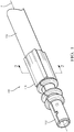
- Figs. 1-3 illustrate a non-limiting example of a conductor assembly 100, hereinafter referred to as the assembly 100.
- the assembly 100 includes an elongate conductor, in this particular example a coaxial electrical cable 102.
- the coaxial cable 102 has a central inner conductor 104, an inner insulator 106 surrounding the inner conductor 104, an outer conductor 108 surrounding the inner insulator 106, and an outer insulator 110 surrounding the inner insulator 106.
- the coaxial cable 102 has a generally circular cross section.
- the assembly 100 also includes a conductive inner terminal (not shown) connected to the inner conductor 104 and a conductive outer terminal 112 surrounding the inner terminal and connected to the outer conductor 108.
- the outer terminal 112 defines a tubular inner ferrule 114 that is disposed intermediate the inner insulator 106 and the outer insulator 110. According to the particular example illustrated in Fig. 2 , the inner ferrule 114 is located intermediate the outer insulator 110 and the outer conductor 108.
- a terminal insulator is disposed between the inner terminal and the outer terminal 112.
- the assembly 100 further includes a generally cylindrical seamless outer ferrule 116 having a surrounding a portion of the outer insulator 110 overlying the inner ferrule 114.
- the outer ferrule 116 is deformed by a crimping tool 300 to define four depressions 118 extending along the outer ferrule 116 in a direction generally parallel to the longitudinal axis X of the outer ferrule 116.
- Each of the four depressions 118 have the same consistent depression radius 122.
- the deformation produces four protrusions 120 extending along the outer ferrule 116 in a direction generally parallel to the longitudinal axis of the outer ferrule 116.
- the four depressions 118 and the four protrusions 120 are evenly spaced about a circumference of the outer ferrule 116.
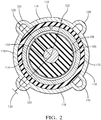
- Adjacent depressions 118 of the four depressions 118 are spaced approximately 90 degrees apart about the longitudinal axis of the outer ferrule 116. As used herein, approximately 90 degrees apart is within a range of 80 to 100 degrees apart. As best shown in Fig. 2 , one of the four protrusions 120 is located intermediate the adjacent depressions 118. Adjacent protrusions 120 of the four protrusions 120 are also spaced approximately 90 degrees apart about the longitudinal axis of the outer ferrule 116. As shown in Figs. 9a and 9b , the depression radius 122 of the four depressions 118 is less than the original ferrule radius 124 of the outer ferrule 116 prior to deformation by the crimping tool 300.
- each of the four protrusions 120 is controlled during the crimping process 700 so that each of the four protrusions 120 is equal to or less than a height threshold 130. Control of the protrusion height 128 is discussed in more detail in the description of the crimping tool 300 below.
- the four depressions 118 and the four protrusions 120 extend along the entire length of the outer ferrule 116.
- only a central portion 226 of the outer ferrule 216 is deformed to form the four depressions 218 and the four protrusions 220.
- the ends of the outer ferrule 216 retain the original ferrule radius 224.
- Figs 4-6 illustrate a non-limiting example of a crimping tool 300 used to crimp the outer ferrule 116, 216 of the coaxial cable assembles 100, 200 shown in Figs. 1 and 3 .
- the crimping tool 300 is configured to form the four evenly spaced depressions 118, 218 and the four evenly spaced protrusions 120, 220 about the circumference of the outer ferrule 116.
- the crimping tool 300 includes four crimping dies 302. Each crimping die 302 of the four crimping dies 302 defines a concave crimping surface 304 having an depression radius 312 that is substantially equal to the depression radius 122 of the formed outer ferrule 116.
- the crimping tool 300 also includes four limiting dies 306. As best shown in Fig. 5 , each limiting die 306 defines a concave limiting surface 308 having a limiting radius 310 that is greater than the depression radius 312 of the crimping dies 302.
- the limiting dies 306 are configured to limit the height 128 of each protrusion to the height threshold 130 and are located intermediate two adjacent crimping dies 302 of the four crimping dies 302.
- Adjacent crimping dies 302 are spaced approximately 90 degrees apart about a longitudinal axis of the crimping tool 300.
- Adjacent limiting dies 306 of the four limiting dies 306 are also spaced approximately 90 degrees apart about the longitudinal axis of the crimping tool 300.
- Each limiting surface 308 is spaced at a distance of the limiting radius 310 from the longitudinal axis of the ferrule. This limiting radius 310 is equal to the original ferrule radius 124 plus the height threshold 130 of the four protrusions 120 of the outer ferrule 116.
- the four limiting dies 306 are integrally formed in a single die assembly 314 and are fixed such that each limiting surface 308 remains at the distance of the limiting radius 310 as the four crimping dies 302 move relative to the longitudinal axis of the tool 300.
- the crimping tool 400 further includes four linkages 410 between each crimping die 402 and an adjoining limiting die 406.
- the four linkages 410 are configured to move each limiting die 406 and hence each limiting surface 408 to the distance of the limiting radius 310 as the four crimping dies 402 move toward the longitudinal axis of the tool 400 as the crimping tool 400 deforms the outer ferrule 116 of the coaxial cable assembly 100.
- Fig.8a illustrates the shape of the outer ferrule 116 prior to forming.
- Fig. 8b illustrate the shape of the outer ferrule 116 after forming it with the crimping tool 300, 400.
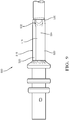
- Fig. 9 illustrates an alternative embodiment of the assembly 500 that includes four indentations 532 produced by deforming the convex bottom surfaces 534 of the four depressions 518.
- the indentations 532 are located adjacent a distal edge 536 of the outer ferrule 516.
- An angle of a surface of the indentation 532 relative to the convex bottom surfaces 534 is in a range of 10 to 20 degrees, preferably 15 degrees.
- Adjacent indentations 532 of the four indentations 532 are spaced approximately 90 degrees apart about the longitudinal axis X of the outer ferrule 516.
- Tables 1 and 2 present a comparison of test results regarding the the performance of assembly 100 and assembly 500 during USCAR 37 Shield Retention tests and USCAR 17 Sequence N - Mechanical Pull tests published by the United States Council for Automotive Research (USCAR). Table 1 USCAR 37 Shield Retention Test Results Assembly 100 Assembly 500 # of Samples 80 6 Max. Force Required to Separate Outer Ferrule 151.9 N 275.8 N Min. Force 97.8 N 250.9 N Avg. Force 123.9 N 257.4 N Std. Deviation ( ⁇ ) 11.95 N 9.13 N Avg.
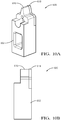
- Figs. 10a and 10b illustrate another alternative embodiment of the crimping tool 600.
- Each of the four crimping dies 602 include a concave crimping surface 616 and a concave indentation surface 618 angled relative to the crimping surface 616.
- the concave crimping surface 616 and the concave indentation surface 618 have the same radius.
- An angle of the indentation surface 618 relative to the crimping surface 616 is in a range of 10 to 20 degrees, preferably 15 degrees.
- the indentation surface 618 is placed near the distal edge 536 of the outer ferrule 516 as the crimping die 602 is applied to the outer ferrule 516.
- Fig. 12 describes a method 700 of manufacturing the coaxial cable assembly 100, 500 described above.
- the method 700 includes the following steps:
- the four crimping dies 302 are spaced approximately 90 degrees apart about the longitudinal axis of the crimping tool 300. After deformation of the outer ferrule 116, adjacent depressions 118 of the four depressions 118 are spaced approximately 90 degrees apart about the longitudinal axis of the outer ferrule 116. One of the four protrusions 120 is located intermediate the adjacent depressions 118. Adjacent protrusions 120 of the four protrusions 120 are spaced approximately 90 degrees apart about the longitudinal axis of the outer ferrule 116.
- a coaxial electrical cable assembly 100 is provided.
- the consistent radius of the depressions 118 and the limited height 128 of the protrusions 120 reduces the variation in capacitance between the inner and outer conductors 104, 110 of the coaxial cable 102 in the area of the outer ferrule 116, thereby reducing the variation of impedance along the coaxial cable assembly 100 which provides improved insertion loss performance.
- the outer ferrule 516 as formed with the four depressions 518, four protrusions 520 and four indentations 532, also provides improved retention of the outer ferrule 516 to the coaxial cable assembly 100.
- the outer ferrule 516, as formed with the four depressions 118 and four protrusions 120 is also more easily accommodated into existing connector body designs having generally cylindrical connector cavities in which the coaxial cable assembly 100 is received.
- a crimping tool 300 configured to form the four depressions 118 and four protrusions 120 in the outer ferrule 116 is also provided.
- the tool 300 includes four crimping dies 302 to form the four depressions 118 in the outer ferrule 116.
- the tool 300 also inclines four limiting dies 306 that limit growth of the four protrusions 120 so that the four protrusions 120 do not exceed a maximum height threshold 130.
- the crimping tool 300 when used with the outer ferrule 116, provides all of the benefits listed above.
- the example presented herein is directed to a coaxial electrical cable assembly 100, however other embodiments may be envisioned that are adapted for use with other types of shielded or unshielded electrical cables. Yet other embodiments of the assembly may be envisioned wherein the conductors are fiber optic cables, pneumatic tubes, or hydraulic tubes.
- 'One or more' includes a function being performed by one element, a function being performed by more than one element, e.g., in a distributed fashion, several functions being performed by one element, several functions being performed by several elements, or any combination of the above.
- first, second, etc. are, in some instances, used herein to describe various elements, these elements should not be limited by these terms. These terms are only used to distinguish one element from another. Moreover, the use of the terms first, second, etc. does not denote any order of importance, but rather the terms first, second, etc. are used to distinguish one element from another. For example, a first contact could be termed a second contact, and, similarly, a second contact could be termed a first contact, without departing from the scope of the various described embodiments. The first contact and the second contact are both contacts, but they are not the same contact.
- the term “if' is, optionally, construed to mean “when” or “upon” or “in response to determining” or “in response to detecting,” depending on the context.
- the phrase “if it is determined” or “if [a stated condition or event] is detected” is, optionally, construed to mean “upon determining” or “in response to determining” or “upon detecting [the stated condition or event]” or “in response to detecting [the stated condition or event],” depending on the context.
- directional terms such as upper, lower, etc. do not denote any particular orientation, but rather the terms upper, lower, etc. are used to distinguish one element from another and establish a relationship between the various elements.
Landscapes
- Engineering & Computer Science (AREA)
- Manufacturing & Machinery (AREA)
- General Engineering & Computer Science (AREA)
- Mechanical Engineering (AREA)
- Manufacturing Of Electrical Connectors (AREA)
- Connections Effected By Soldering, Adhesion, Or Permanent Deformation (AREA)
- Insulated Conductors (AREA)
Abstract
Description
- The invention generally relates to a conductor assembly particularly a conductor assembly including a tubular ferrule.
- According to one embodiment of the invention a cable assembly is provided. The cable assembly includes an elongate conductor surrounded by an outer insulator and an outer ferrule surrounding a portion of the conductor. An outer surface of the outer ferrule is deformed to produce an indentation having an indentation surface that is angled relative to the outer surface. The indentation forms a barb that at least partially penetrates the outer insulator.
- In an example embodiment having one or more features of the cable assembly of the previous paragraph, the indentation is located adjacent a distal edge of the outer ferrule.
- In an example embodiment having one or more features of the cable assembly of the previous paragraph, an angle of the indentation surface relative to the outer surface is in a range of 10 to 20 degrees.
- In an example embodiment having one or more features of the cable assembly of the previous paragraph, the elongate conductor has a generally circular cross section. The outer ferrule is seamless and has a generally cylindrical shape having a ferrule radius. The outer ferrule is deformed to define four depressions each having a convex bottom surface and four protrusions evenly spaced about a circumference of the outer ferrule. The convex bottom surfaces have a convex radius that is less than the ferrule radius. The convex bottom surfaces are formed by the outer surface and are deformed to produce four indentations.
- In an example embodiment having one or more features of the cable assembly of the previous paragraph, adjacent depressions of the four depressions are spaced approximately 90 degrees apart about a longitudinal axis of the outer ferrule. One of the four protrusions is located intermediate the adjacent depressions. Adjacent protrusions of the four protrusions are spaced approximately 90 degrees apart about the longitudinal axis of the outer ferrule. Adjacent indentations of the four indentations are spaced approximately 90 degrees apart about the longitudinal axis of the outer ferrule.
- In an example embodiment having one or more features of the cable assembly of the previous paragraph, the elongate conductor is a coaxial electrical cable comprising a central inner conductor, an inner insulator surrounding the inner conductor, an outer conductor surrounding the inner insulator, and the outer insulator surrounding the outer conductor.
- In an example embodiment having one or more features of the cable assembly of the previous paragraph, the cable assembly further includes an inner ferrule that is disposed intermediate the outer conductor and the inner insulator.
- In an example embodiment having one or more features of the cable assembly of the previous paragraph, a portion of the outer ferrule retains the ferrule radius after deformation.
- In an example embodiment having one or more features of the cable assembly of the previous paragraph, each of the four protrusions has a height that is less than a height threshold.
- In an example embodiment having one or more features of the cable assembly of the previous paragraph, the four indentations have the convex radius.
- In another embodiment of the invention, a method of manufacturing a coaxial cable assembly is presented. The method includes the steps of
- a) providing a coaxial electrical cable comprising a central inner conductor, an inner insulator surrounding the inner conductor, an outer conductor surrounding the inner insulator, and an outer insulator surrounding the outer conductor;
- b) providing a generally cylindrical seamless outer ferrule having a ferrule radius;
- c) providing a crimping tool including four crimping dies each having a first die face defining a consistent depression radius that is less than the ferrule radius and a second die face that is angled relative to the first die face;
- d) placing the outer ferrule over a portion of the outer insulator;
- e) deforming the outer ferrule using the crimping tool to form four depressions and four protrusions in the outer ferrule that are evenly spaced about a circumference of the outer ferrule, wherein the four depressions each are characterized as having the depression radius; and
- f) deforming the four depressions to form four indentations, each indentation having an indentation surface that is angled relative to an outer surface of each of the four depressions and wherein each indentation forms a barb that at least partially penetrates the outer insulator.
- In an example embodiment having one or more features of the method of the previous paragraph, the four indentations are located adjacent a distal edge of the outer ferrule.
- In an example embodiment having one or more features of the method of the previous paragraph, an angle of the indentation surface relative to the outer surface is in a range of 10 to 20 degrees.
- In an example embodiment having one or more features of the method of the previous paragraph, adjacent depressions of the four depressions are spaced approximately 90 degrees apart about a longitudinal axis of the outer ferrule, wherein one of the four protrusions is located intermediate the adjacent depressions. Adjacent protrusions of the four protrusions are spaced approximately 90 degrees apart about the longitudinal axis of the outer ferrule. Adjacent indentations of the four indentations are spaced approximately 90 degrees apart about the longitudinal axis of the outer ferrule.
- In an example embodiment having one or more features of the method of the previous paragraph, a portion of the outer ferrule retains the ferrule radius after deformation. Each of the four protrusions has a height that is less than a height threshold.
- In yet another embodiment of the invention, a tool configured to form four evenly spaced depressions having an depression radius and four evenly spaced protrusions about a circumference of a generally cylindrical seamless ferrule having a ferrule radius, each protrusion of the four protrusions having a protrusion height equal to or less than a height threshold, said tool further configured to form four indentations, each indentation having an indentation surface that is angled relative to an outer surface of each of the four depressions is provided. The tool includes four crimping dies. Each crimping die of the four crimping dies defines a concave crimping surface having the depression radius and a concave indentation surface angled relative to the crimping surface. The indentation surface also has the depression radius. The tool further includes four limiting dies. Each limiting die is located intermediate two adjacent crimping dies of the four crimping dies and defines a limiting surface configured to limit a height of each protrusion to the height threshold.
- In an example embodiment having one or more features of the tool of the previous paragraph, adjacent crimping dies are spaced approximately 90 degrees apart about a longitudinal axis and wherein adjacent limiting dies of the four limiting dies are spaced approximately 90 degrees apart about the longitudinal axis.
- In an example embodiment having one or more features of the tool of the previous paragraph, each limiting surface is spaced a limiting distance from the longitudinal axis of the outer ferrule. The limiting distance is equal to the ferrule radius plus the height threshold.
- In an example embodiment having one or more features of the tool of the previous paragraph, the four limiting dies are fixed such that each limiting surface remains at the limiting distance as the four crimping dies move relative to the longitudinal axis of the outer ferrule.
- In an example embodiment having one or more features of the tool of the previous paragraph, the tool further includes four linkages between each crimping die and an adjoining limiting die. The four linkages are configured to move each limiting surface of each limiting die to the limiting distance as the four crimping dies move toward the longitudinal axis of the outer ferrule.
- The present invention will now be described, by way of example with reference to the accompanying drawings, in which:
-
Fig. 1 is a perspective view of a conductor assembly including a crimped tubular ferrule according to one embodiment; -
Fig. 2 is a cross section view of the conductor assembly ofFig. 1 according to one embodiment; -
Fig. 3 is a perspective view of a conductor assembly including a crimped tubular ferrule according to one embodiment; -
Fig. 4 is a front end view of a crimping tool having fixed limiting dies used to form the tubular ferrule of the conductor assembly ofFigs. 1 or3 according to one embodiment; -
Fig. 5 is a close up front end view of the crimping dies and limiting dies of the crimping tool ofFig. 4 according to one embodiment; -
Fig. 6 is a perspective side view of the crimping tool ofFig. 4 with one of the crimping dies removed to better show the limiting dies according to one embodiment; -
Fig. 7 is a front end view of a crimping tool having moveable limiting dies used to form the tubular ferrule of the conductor assembly ofFigs. 1 or3 according to one embodiment; -
Fig. 8a is a perspective and end view of a tubular ferrule of the conductor assembly ofFigs. 1 and3 prior to forming with the crimping tool ofFig. 4 or7 according to one embodiment; -
Fig. 8b is a perspective and end view of the tubular ferrule of the conductor assembly ofFig 8a after forming with the crimping tool ofFig. 4 or7 according to one embodiment; -
Fig 9 is a side view of a conductor assembly including an indentation that forms a barb penetrating the outer insulator according to one embodiment; -
Fig 10a is a perspective view of a crimping tool configured to form the indentation ofFig. 9 according to one embodiment; -
Fig 10b is a side view of the crimping tool ofFig. 11a according to one embodiment; -
Fig. 11 is a side view of the tool ofFig. 10a in relation to the conductor assembly ofFig. 9 after forming the indentation according to one embodiment; and -
Fig. 12 is a flow chart of a method of manufacturing the conductor assemblies ofFigs. 1 ,3 , or9 using the crimping tool ofFigs. 4 ,7 , or10a-b according to one embodiment; - Reference will now be made in detail to embodiments, examples of which are illustrated in the accompanying drawings. In the following detailed description, numerous specific details are set forth in order to provide a thorough understanding of the various described embodiments. However, it will be apparent to one of ordinary skill in the art that the various described embodiments may be practiced without these specific details. In other instances, well-known methods, procedures, components, circuits, and networks have not been described in detail so as not to unnecessarily obscure aspects of the embodiments.
- Presented herein is a conductor assembly that includes a seamless tubular ferrule that is crimped to an elongate conductor. The tubular ferrule is deformed in a crimping process to attach the ferrule to the conductor. After crimping, the ferrule defines four depressions having a consistent radius and four protrusions evenly spaced about a circumference of the ferrule. A tool used to deform the ferrule which limits the height four protrusions is also presented herein.
-
Figs. 1-3 illustrate a non-limiting example of aconductor assembly 100, hereinafter referred to as theassembly 100. As shown inFig. 3 , theassembly 100 includes an elongate conductor, in this particular example a coaxialelectrical cable 102. Thecoaxial cable 102 has a centralinner conductor 104, aninner insulator 106 surrounding theinner conductor 104, anouter conductor 108 surrounding theinner insulator 106, and anouter insulator 110 surrounding theinner insulator 106. As shown inFig. 2 , thecoaxial cable 102 has a generally circular cross section. - The
assembly 100 also includes a conductive inner terminal (not shown) connected to theinner conductor 104 and a conductiveouter terminal 112 surrounding the inner terminal and connected to theouter conductor 108. Theouter terminal 112 defines a tubularinner ferrule 114 that is disposed intermediate theinner insulator 106 and theouter insulator 110. According to the particular example illustrated inFig. 2 , theinner ferrule 114 is located intermediate theouter insulator 110 and theouter conductor 108. A terminal insulator is disposed between the inner terminal and theouter terminal 112. - The
assembly 100 further includes a generally cylindrical seamlessouter ferrule 116 having a surrounding a portion of theouter insulator 110 overlying theinner ferrule 114. Theouter ferrule 116 is deformed by a crimpingtool 300 to define fourdepressions 118 extending along theouter ferrule 116 in a direction generally parallel to the longitudinal axis X of theouter ferrule 116. Each of the fourdepressions 118 have the sameconsistent depression radius 122. The deformation produces fourprotrusions 120 extending along theouter ferrule 116 in a direction generally parallel to the longitudinal axis of theouter ferrule 116. The fourdepressions 118 and the fourprotrusions 120 are evenly spaced about a circumference of theouter ferrule 116.Adjacent depressions 118 of the fourdepressions 118 are spaced approximately 90 degrees apart about the longitudinal axis of theouter ferrule 116. As used herein, approximately 90 degrees apart is within a range of 80 to 100 degrees apart. As best shown inFig. 2 , one of the fourprotrusions 120 is located intermediate theadjacent depressions 118.Adjacent protrusions 120 of the fourprotrusions 120 are also spaced approximately 90 degrees apart about the longitudinal axis of theouter ferrule 116. As shown inFigs. 9a and 9b , thedepression radius 122 of the fourdepressions 118 is less than theoriginal ferrule radius 124 of theouter ferrule 116 prior to deformation by the crimpingtool 300. - The
height 128 of each of the fourprotrusions 120 is controlled during the crimpingprocess 700 so that each of the fourprotrusions 120 is equal to or less than aheight threshold 130. Control of theprotrusion height 128 is discussed in more detail in the description of the crimpingtool 300 below. - As shown in
Fig. 1 , the fourdepressions 118 and the fourprotrusions 120 extend along the entire length of theouter ferrule 116. According to an alternative embodiment of theassembly 200 shown inFig. 3 , only acentral portion 226 of theouter ferrule 216 is deformed to form the fourdepressions 218 and the fourprotrusions 220. The ends of theouter ferrule 216 retain theoriginal ferrule radius 224. -
Figs 4-6 illustrate a non-limiting example of a crimpingtool 300 used to crimp theouter ferrule Figs. 1 and3 . The crimpingtool 300 is configured to form the four evenly spaceddepressions protrusions outer ferrule 116. As shown inFig. 4 , the crimpingtool 300 includes four crimping dies 302. Each crimping die 302 of the four crimping dies 302 defines a concave crimpingsurface 304 having andepression radius 312 that is substantially equal to thedepression radius 122 of the formedouter ferrule 116. The crimpingtool 300 also includes four limiting dies 306. As best shown inFig. 5 , each limiting die 306 defines a concave limitingsurface 308 having a limitingradius 310 that is greater than thedepression radius 312 of the crimping dies 302. The limiting dies 306 are configured to limit theheight 128 of each protrusion to theheight threshold 130 and are located intermediate two adjacent crimping dies 302 of the four crimping dies 302. Adjacent crimping dies 302 are spaced approximately 90 degrees apart about a longitudinal axis of the crimpingtool 300. Adjacent limiting dies 306 of the four limiting dies 306 are also spaced approximately 90 degrees apart about the longitudinal axis of the crimpingtool 300. - Each limiting
surface 308 is spaced at a distance of the limitingradius 310 from the longitudinal axis of the ferrule. This limitingradius 310 is equal to theoriginal ferrule radius 124 plus theheight threshold 130 of the fourprotrusions 120 of theouter ferrule 116. - According to the embodiment of the crimping
tool 300 shown inFig. 6 , the four limiting dies 306 are integrally formed in asingle die assembly 314 and are fixed such that each limitingsurface 308 remains at the distance of the limitingradius 310 as the four crimping dies 302 move relative to the longitudinal axis of thetool 300. - According to an alternative embodiment of the crimping
tool 400 shown inFig. 7 , the crimpingtool 400 further includes fourlinkages 410 between each crimping die 402 and an adjoining limitingdie 406. The fourlinkages 410 are configured to move each limiting die 406 and hence each limitingsurface 408 to the distance of the limitingradius 310 as the four crimping dies 402 move toward the longitudinal axis of thetool 400 as the crimpingtool 400 deforms theouter ferrule 116 of thecoaxial cable assembly 100. -
Fig.8a illustrates the shape of theouter ferrule 116 prior to forming.Fig. 8b illustrate the shape of theouter ferrule 116 after forming it with the crimpingtool -
Fig. 9 illustrates an alternative embodiment of theassembly 500 that includes fourindentations 532 produced by deforming the convex bottom surfaces 534 of the fourdepressions 518. Theindentations 532 are located adjacent adistal edge 536 of theouter ferrule 516. An angle of a surface of theindentation 532 relative to the convex bottom surfaces 534 is in a range of 10 to 20 degrees, preferably 15 degrees.Adjacent indentations 532 of the fourindentations 532 are spaced approximately 90 degrees apart about the longitudinal axis X of theouter ferrule 516. The inventors have confirmed through testing that the addition of theindentations 532 improve the integrity of theassembly 500 by increasing the force required to separate theouter ferrule 516 from theassembly 500. Tables 1 and 2 present a comparison of test results regarding the the performance ofassembly 100 andassembly 500 during USCAR 37 Shield Retention tests and USCAR 17 Sequence N - Mechanical Pull tests published by the United States Council for Automotive Research (USCAR).Table 1 USCAR 37 Shield Retention Test Results Assembly 100 Assembly 500# of Samples 80 6 Max. Force Required to Separate Outer Ferrule 151.9 N 275.8 N Min. Force 97.8 N 250.9 N Avg. Force 123.9 N 257.4 N Std. Deviation (σ) 11.95 N 9.13 N Avg. - 3σ 88.05 N 230 N Minimum Requirement 150 N Result Fail Pass Necessary Deviation from Requirement 80 N N/A Table 2 USCAR 17 Sequence N - Mechanical Pull Test Results Assembly 100 Assembly 500# of Samples 12 12 # Passing 3 12 % Passing 25% 100% -
Figs. 10a and 10b illustrate another alternative embodiment of the crimpingtool 600. Each of the four crimping dies 602 include a concave crimpingsurface 616 and aconcave indentation surface 618 angled relative to the crimpingsurface 616. The concave crimpingsurface 616 and theconcave indentation surface 618 have the same radius. An angle of theindentation surface 618 relative to the crimpingsurface 616 is in a range of 10 to 20 degrees, preferably 15 degrees. - As shown in
Fig. 11 , theindentation surface 618 is placed near thedistal edge 536 of theouter ferrule 516 as the crimpingdie 602 is applied to theouter ferrule 516. -
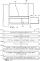
Fig. 12 describes amethod 700 of manufacturing thecoaxial cable assembly method 700 includes the following steps: -
STEP 710, PROVIDE A COAXIAL ELECTRICAL CABLE, includes providing a coaxialelectrical cable 102 comprising a centralinner conductor 104, aninner insulator 106 surrounding theinner conductor 104, anouter conductor 108 surrounding theinner insulator 106, and anouter insulator 110 surrounding theinner insulator 106; -
STEP 712, PROVIDE AN OUTER FERRULE, includes providing a generally cylindrical seamlessouter ferrule 116 having aferrule radius 124; -
STEP 714, PROVIDE A TERMINAL HAVING AN INNER FERRULE, is an optional step that includes providing a terminal having aninner ferrule 114; -
STEP 716, PROVIDE A CRIMPING TOOL, includes providing a crimpingtool 300 including four crimping dies 302 each having adie face 304 defining aconsistent depression radius 312 that is less than theferrule radius 124; -
STEP 718, DISPOSE THE INNER FERRULE INTERMEDIATE AN OUTER INSULATOR AND AN OUTER CONDUCTOR OF THE COAXIAL CABLE, is an optional step that includes disposing theinner ferrule 114 intermediate theouter insulator 110 and theouter conductor 108 prior toSTEP 722, DEFORM THE OUTER FERRULE USING THE CRIMPING TOOL; -
STEP 720, PLACE THE OUTER FERRULE OVER A PORTION OF THE OUTER INSULATOR, includes placing theouter ferrule 116 over a portion of theouter insulator 110; and -
STEP 722, DEFORM THE OUTER FERRULE USING THE CRIMPING TOOL, includes deforming theouter ferrule 116 using the crimpingtool depressions 118 and fourprotrusions 120 in theouter ferrule 116 that are evenly spaced about a circumference of theouter ferrule 116. Theouter ferrule 116 is held between the four crimping dies 302 so that the longitudinal axis of theouter ferrule 116 is substantially coincident with the longitudinal axis of the crimpingtool 300. The four crimping dies 302 are brought simultaneously toward the longitudinal axes to provide substantially consistent pressure and deformation rates when forming the fourdepressions 118 and the fourprotrusions 120. The fourdepressions 118 each are characterized as having thedepression radius 122.STEP 722 may further include deforming the fourdepressions 518 to form fourindentations 532. Eachindentation 532 has an indentation surface that is angled relative to an outer surface of each of the fourdepressions 518. Eachindentation 532 forms a barb that at least partially penetrates theouter insulator 110. - The four crimping dies 302 are spaced approximately 90 degrees apart about the longitudinal axis of the crimping
tool 300. After deformation of theouter ferrule 116,adjacent depressions 118 of the fourdepressions 118 are spaced approximately 90 degrees apart about the longitudinal axis of theouter ferrule 116. One of the fourprotrusions 120 is located intermediate theadjacent depressions 118.Adjacent protrusions 120 of the fourprotrusions 120 are spaced approximately 90 degrees apart about the longitudinal axis of theouter ferrule 116. - Accordingly, a coaxial
electrical cable assembly 100 is provided. The consistent radius of thedepressions 118 and thelimited height 128 of theprotrusions 120 reduces the variation in capacitance between the inner andouter conductors coaxial cable 102 in the area of theouter ferrule 116, thereby reducing the variation of impedance along thecoaxial cable assembly 100 which provides improved insertion loss performance. Theouter ferrule 516, as formed with the fourdepressions 518, fourprotrusions 520 and fourindentations 532, also provides improved retention of theouter ferrule 516 to thecoaxial cable assembly 100. Theouter ferrule 516, as formed with the fourdepressions 118 and fourprotrusions 120, is also more easily accommodated into existing connector body designs having generally cylindrical connector cavities in which thecoaxial cable assembly 100 is received. - Accordingly, a crimping
tool 300 configured to form the fourdepressions 118 and fourprotrusions 120 in theouter ferrule 116 is also provided. Thetool 300 includes four crimping dies 302 to form the fourdepressions 118 in theouter ferrule 116. Thetool 300 also inclines four limiting dies 306 that limit growth of the fourprotrusions 120 so that the fourprotrusions 120 do not exceed amaximum height threshold 130. The crimpingtool 300, when used with theouter ferrule 116, provides all of the benefits listed above. - The example presented herein is directed to a coaxial
electrical cable assembly 100, however other embodiments may be envisioned that are adapted for use with other types of shielded or unshielded electrical cables. Yet other embodiments of the assembly may be envisioned wherein the conductors are fiber optic cables, pneumatic tubes, or hydraulic tubes. - While this invention has been described in terms of the preferred embodiments thereof, it is not intended to be so limited, but rather only to the extent set forth in the claims that follow. For example, the above-described embodiments (and/or aspects thereof) may be used in combination with each other. In addition, many modifications may be made to configure a particular situation or material to the teachings of the invention without departing from its scope. Dimensions, types of materials, orientations of the various components, and the number and positions of the various components described herein are intended to define parameters of certain embodiments, and are by no means limiting and are merely prototypical embodiments.
- Many other embodiments and modifications within the spirit and scope of the claims will be apparent to those of skill in the art upon reviewing the above description. The scope of the invention should, therefore, be determined with reference to the following claims, along with the full scope of equivalents to which such claims are entitled.
- As used herein, 'One or more' includes a function being performed by one element, a function being performed by more than one element, e.g., in a distributed fashion, several functions being performed by one element, several functions being performed by several elements, or any combination of the above.
- It will also be understood that, although the terms first, second, etc. are, in some instances, used herein to describe various elements, these elements should not be limited by these terms. These terms are only used to distinguish one element from another. Moreover, the use of the terms first, second, etc. does not denote any order of importance, but rather the terms first, second, etc. are used to distinguish one element from another. For example, a first contact could be termed a second contact, and, similarly, a second contact could be termed a first contact, without departing from the scope of the various described embodiments. The first contact and the second contact are both contacts, but they are not the same contact.
- The terminology used in the description of the various described embodiments herein is for the purpose of describing particular embodiments only and is not intended to be limiting. As used in the description of the various described embodiments and the appended claims, the singular forms "a", "an" and "the" are intended to include the plural forms as well, unless the context clearly indicates otherwise. It will also be understood that the term "and/or" as used herein refers to and encompasses any and all possible combinations of one or more of the associated listed items. It will be further understood that the terms "includes," "including," "comprises," and/or "comprising," when used in this specification, specify the presence of stated features, integers, steps, operations, elements, and/or components, but do not preclude the presence or addition of one or more other features, integers, steps, operations, elements, components, and/or groups thereof.
- As used herein, the term "if' is, optionally, construed to mean "when" or "upon" or "in response to determining" or "in response to detecting," depending on the context. Similarly, the phrase "if it is determined" or "if [a stated condition or event] is detected" is, optionally, construed to mean "upon determining" or "in response to determining" or "upon detecting [the stated condition or event]" or "in response to detecting [the stated condition or event]," depending on the context.
- Additionally, directional terms such as upper, lower, etc. do not denote any particular orientation, but rather the terms upper, lower, etc. are used to distinguish one element from another and establish a relationship between the various elements.
Claims (15)
- A cable assembly (500), comprising:an elongate conductor (100) surrounded by an outer insulator (110); andan outer ferrule (516) surrounding a portion of the conductor (100),wherein an outer surface of the outer ferrule (516) is deformed to produce an indentation (532) having an indentation surface that is angled relative to the outer surface and wherein the indentation (532) forms a barb that at least partially penetrates the outer insulator (110).
- The cable assembly (500) according to claim 1, wherein the indentation (532) is located adjacent a distal edge (536) of the outer ferrule (516).
- The cable assembly (500) according to claim 1 or 2, wherein an angle of the indentation surface (618) relative to the outer surface is in a range of 10 to 20 degrees.
- The cable assembly (500) according to any one of the preceding claims, wherein the elongate conductor (100) has a generally circular cross section, wherein the outer ferrule (516) is seamless and has a generally cylindrical shape having a ferrule radius (124), wherein the outer ferrule (516) is deformed to define four depressions (518) each having a convex bottom surface (534) and four protrusions (520) evenly spaced about a circumference of the outer ferrule (516), wherein the convex bottom surfaces (534) have a convex radius that is less than the ferrule radius (124), and wherein the convex bottom surfaces (534) are said outer surface and are deformed to produce four indentations (532).
- The cable assembly (500) according to any one of the preceding claims, wherein adjacent depressions (518) of the four depressions (518) are spaced approximately 90 degrees apart about a longitudinal axis (X) of the outer ferrule (516), wherein one of the four protrusions (520) is located intermediate the adjacent depressions (518), wherein adjacent protrusions (520) of the four protrusions (520) are spaced approximately 90 degrees apart about the longitudinal axis (X) of the outer ferrule (516), and wherein adjacent indentations (532) of the four indentations (532) are spaced approximately 90 degrees apart about the longitudinal axis (X) of the outer ferrule (516).
- The method (700) of manufacturing a coaxial cable assembly (100) comprising the steps of:providing a coaxial electrical cable (102) comprising a central inner conductor (104), an inner insulator (106) surrounding the inner conductor (104), an outer conductor (108) surrounding the inner insulator (106), and an outer insulator (110) surrounding the outer conductor (108);providing a generally cylindrical seamless outer ferrule (516) having a ferrule radius (124);providing a crimping tool (600) including four crimping dies (602) each having a first die face (604) defining a consistent depression radius (122) that is less than the ferrule radius (124) and a second die face (618) that is angled relative to the first die face (604);placing the outer ferrule (116) over a portion of the outer insulator (110);deforming the outer ferrule (516) using the crimping tool (600) to form four depressions (518) and four protrusions (520) in the outer ferrule (516) that are evenly spaced about a circumference of the outer ferrule (516), wherein the four depressions (518) each are characterized as having the depression radius (122); anddeforming the four depressions (518) to form four indentations (532), each indentation (532) having an indentation surface that is angled relative to an outer surface of each of the four depressions (518) and wherein each indentation (532) forms a barb that at least partially penetrates the outer insulator (110).
- The method (700) according to claim 6, wherein the four indentations (532) are located adjacent a distal edge (536) of the outer ferrule (516).
- The method (700) according to claim 6 or 7, wherein an angle of the indentation surface relative to the outer surface is in a range of 10 to 20 degrees.
- The method (700) according to any one of the claims 6 to 8, wherein adjacent depressions (518) of the four depressions (518) are spaced approximately 90 degrees apart about a longitudinal axis (X) of the outer ferrule (516), wherein one of the four protrusions (520) is located intermediate the adjacent depressions (518), wherein adjacent protrusions (520) of the four protrusions (520) are spaced approximately 90 degrees apart about the longitudinal axis (X) of the outer ferrule (516), and wherein adjacent indentations (532) of the four indentations (532) are spaced approximately 90 degrees apart about the longitudinal axis (X) of the outer ferrule (516).
- The method (700) according to any one of the claims 6 to 9, wherein a portion of the outer ferrule (516) retains the ferrule radius (124) after deformation and wherein each of the four protrusions (520) has a height (128) that is less than a height threshold (130).
- A tool (600) configured to form four evenly spaced depressions (118) having an depression radius (122) and four evenly spaced protrusions (520) about a circumference of a generally cylindrical seamless ferrule (516) having a ferrule radius (124), each protrusion of the four protrusions (520) having a protrusion height (128) equal to or less than a height threshold (130), said tool (600) further configured to form four indentations (532), each indentation (532) having an indentation surface that is angled relative to an outer surface of each of the four depressions (518), said tool (600) comprising:four crimping dies (602), each crimping die (602) of the four crimping dies (602) defining a concave crimping surface (604) having the depression radius (122) and a concave indentation surface (618) angled relative to the crimping surface (604), said indentation surface also having the depression radius (122); andfour limiting dies (306), each limiting die (306) located intermediate two adjacent crimping dies (602) of the four crimping dies (602) and defining a limiting surface (308) configured to limit a height (128) of each protrusion to the height threshold (130).
- The tool (600) according to claim 11, wherein adjacent crimping dies (602) are spaced approximately 90 degrees apart about a longitudinal axis (X) and wherein adjacent limiting dies (306) of the four limiting dies (306) are spaced approximately 90 degrees apart about the longitudinal axis (X).
- The tool (600) according to claim 11 or 12, wherein each limiting surface (308) is spaced a limiting distance from the longitudinal axis (X) of the outer ferrule (516) and wherein the limiting distance is equal to the ferrule radius (124) plus the height threshold (130).
- The tool (600) according to any one of the claims 11 to 13, wherein the four limiting dies (306) are fixed such that each limiting surface (308) remains at the limiting distance as the four crimping dies (602) move relative to the longitudinal axis (X) of the outer ferrule (516).
- The tool (600) according to any one of the claims 11 to 14, wherein the tool (300) further comprises four linkages (410) between each crimping die (602) and an adjoining limiting die (406), said four linkages (410) configured to move each limiting surface (308) of each limiting die (306) to the limiting distance as the four crimping dies (602) move toward the longitudinal axis (X) of the outer ferrule (516).
Applications Claiming Priority (1)
| Application Number | Priority Date | Filing Date | Title |
|---|---|---|---|
| US16/019,666 US10361496B1 (en) | 2018-03-26 | 2018-06-27 | Conductor assembly with a crimped tubular ferrule and method and tool for manufacturing same |
Publications (2)
| Publication Number | Publication Date |
|---|---|
| EP3588680A1 true EP3588680A1 (en) | 2020-01-01 |
| EP3588680B1 EP3588680B1 (en) | 2021-08-04 |
Family
ID=66912684
Family Applications (1)
| Application Number | Title | Priority Date | Filing Date |
|---|---|---|---|
| EP19180520.9A Active EP3588680B1 (en) | 2018-06-27 | 2019-06-17 | Conductor assembly with a crimped tubular ferrule and method and tool for manufacturing same |
Country Status (4)
| Country | Link |
|---|---|
| EP (1) | EP3588680B1 (en) |
| JP (1) | JP6816220B2 (en) |
| KR (1) | KR102202299B1 (en) |
| CN (1) | CN110649401B (en) |
Cited By (1)
| Publication number | Priority date | Publication date | Assignee | Title |
|---|---|---|---|---|
| EP3852197A1 (en) * | 2020-01-20 | 2021-07-21 | TE Connectivity Germany GmbH | Arrangement, tool and method for producing such an arrangement |
Citations (5)
| Publication number | Priority date | Publication date | Assignee | Title |
|---|---|---|---|---|
| US2226849A (en) * | 1936-07-03 | 1940-12-31 | Kingston Products Corp | Electrical connection means |
| NL9101669A (en) * | 1991-10-03 | 1993-05-03 | Robert Jan Odinot | Coaxial plug connection |
| GB2300765A (en) * | 1995-05-12 | 1996-11-13 | Bicc Plc | Electric cable terminations and methods of making them |
| US5685072A (en) * | 1995-09-28 | 1997-11-11 | Osram Sylvania Inc. | Cable clamp apparatus and method |
| EP1930988A2 (en) * | 2006-12-04 | 2008-06-11 | Hosiden Corporation | Cable attachment, cable assembly including the same, and connector including the attachment |
Family Cites Families (3)
| Publication number | Priority date | Publication date | Assignee | Title |
|---|---|---|---|---|
| US3234776A (en) * | 1963-09-04 | 1966-02-15 | Amp Inc | Crimping device |
| US8827744B2 (en) * | 2011-07-29 | 2014-09-09 | Delphi Technologies, Inc. | Wire cable assembly |
| CN203367549U (en) * | 2013-05-07 | 2013-12-25 | 四川爱通电子线缆制造有限责任公司 | Coaxial cable connector |
-
2019
- 2019-06-17 EP EP19180520.9A patent/EP3588680B1/en active Active
- 2019-06-20 KR KR1020190073342A patent/KR102202299B1/en active Active
- 2019-06-24 CN CN201910547567.3A patent/CN110649401B/en active Active
- 2019-06-25 JP JP2019117171A patent/JP6816220B2/en active Active
Patent Citations (5)
| Publication number | Priority date | Publication date | Assignee | Title |
|---|---|---|---|---|
| US2226849A (en) * | 1936-07-03 | 1940-12-31 | Kingston Products Corp | Electrical connection means |
| NL9101669A (en) * | 1991-10-03 | 1993-05-03 | Robert Jan Odinot | Coaxial plug connection |
| GB2300765A (en) * | 1995-05-12 | 1996-11-13 | Bicc Plc | Electric cable terminations and methods of making them |
| US5685072A (en) * | 1995-09-28 | 1997-11-11 | Osram Sylvania Inc. | Cable clamp apparatus and method |
| EP1930988A2 (en) * | 2006-12-04 | 2008-06-11 | Hosiden Corporation | Cable attachment, cable assembly including the same, and connector including the attachment |
Cited By (3)
| Publication number | Priority date | Publication date | Assignee | Title |
|---|---|---|---|---|
| EP3852197A1 (en) * | 2020-01-20 | 2021-07-21 | TE Connectivity Germany GmbH | Arrangement, tool and method for producing such an arrangement |
| JP2021114464A (en) * | 2020-01-20 | 2021-08-05 | ティーイー コネクティビティ ジャーマニー ゲゼルシャフト ミット ベシュレンクテル ハフツンクTE Connectivity Germany GmbH | Apparatus, tool, and method for forming apparatus |
| US12068569B2 (en) | 2020-01-20 | 2024-08-20 | Te Connectivity Germany Gmbh | Arrangement, tool and method for producing such an arrangement |
Also Published As
| Publication number | Publication date |
|---|---|
| JP6816220B2 (en) | 2021-01-20 |
| CN110649401B (en) | 2021-07-06 |
| CN110649401A (en) | 2020-01-03 |
| EP3588680B1 (en) | 2021-08-04 |
| KR102202299B1 (en) | 2021-01-14 |
| JP2020043055A (en) | 2020-03-19 |
| KR20200001504A (en) | 2020-01-06 |
Similar Documents
| Publication | Publication Date | Title |
|---|---|---|
| US10355379B1 (en) | Conductor assembly with a crimped tubular ferrule and method of manufacturing same | |
| EP3569326A1 (en) | Ferrule crimping tool | |
| US10741975B2 (en) | Sheilded cable assembly and electromagnetic shield terminal assembly for same | |
| US8834215B2 (en) | Electrical contact element | |
| US20170324172A1 (en) | Electrical crimp terminal | |
| US9698553B2 (en) | Method for manufacturing terminal-fitted wire | |
| US10361496B1 (en) | Conductor assembly with a crimped tubular ferrule and method and tool for manufacturing same | |
| US9882320B2 (en) | Coaxial cable connector | |
| US5607320A (en) | Cable clamp apparatus | |
| US10008786B2 (en) | Coaxial-cable-assembly, ferrule, and method of making the same | |
| EP3588680B1 (en) | Conductor assembly with a crimped tubular ferrule and method and tool for manufacturing same | |
| US11095076B2 (en) | Cable connector | |
| US11417979B2 (en) | Shielded electrical connector assembly and method of manufacturing same | |
| US10516238B2 (en) | Method for forming a shielded electrical terminal and an electrical terminal formed by said method | |
| DE102020108211A1 (en) | Electrical connection, electrical connector assembly and method of making the same | |
| US4272150A (en) | Electrical contact for an electrical connector | |
| US11349241B2 (en) | Power socket for electrical connector system | |
| EP4693749A1 (en) | Electrical cable terminal with crimping wings and method of manufacturing thereof | |
| EP2790278B1 (en) | Crimp die |
Legal Events
| Date | Code | Title | Description |
|---|---|---|---|
| PUAI | Public reference made under article 153(3) epc to a published international application that has entered the european phase |
Free format text: ORIGINAL CODE: 0009012 |
|
| STAA | Information on the status of an ep patent application or granted ep patent |
Free format text: STATUS: THE APPLICATION HAS BEEN PUBLISHED |
|
| AK | Designated contracting states |
Kind code of ref document: A1 Designated state(s): AL AT BE BG CH CY CZ DE DK EE ES FI FR GB GR HR HU IE IS IT LI LT LU LV MC MK MT NL NO PL PT RO RS SE SI SK SM TR |
|
| AX | Request for extension of the european patent |
Extension state: BA ME |
|
| STAA | Information on the status of an ep patent application or granted ep patent |
Free format text: STATUS: REQUEST FOR EXAMINATION WAS MADE |
|
| 17P | Request for examination filed |
Effective date: 20200625 |
|
| RBV | Designated contracting states (corrected) |
Designated state(s): AL AT BE BG CH CY CZ DE DK EE ES FI FR GB GR HR HU IE IS IT LI LT LU LV MC MK MT NL NO PL PT RO RS SE SI SK SM TR |
|
| GRAP | Despatch of communication of intention to grant a patent |
Free format text: ORIGINAL CODE: EPIDOSNIGR1 |
|
| STAA | Information on the status of an ep patent application or granted ep patent |
Free format text: STATUS: GRANT OF PATENT IS INTENDED |
|
| GRAS | Grant fee paid |
Free format text: ORIGINAL CODE: EPIDOSNIGR3 |
|
| INTG | Intention to grant announced |
Effective date: 20210507 |
|
| GRAA | (expected) grant |
Free format text: ORIGINAL CODE: 0009210 |
|
| STAA | Information on the status of an ep patent application or granted ep patent |
Free format text: STATUS: THE PATENT HAS BEEN GRANTED |
|
| AK | Designated contracting states |
Kind code of ref document: B1 Designated state(s): AL AT BE BG CH CY CZ DE DK EE ES FI FR GB GR HR HU IE IS IT LI LT LU LV MC MK MT NL NO PL PT RO RS SE SI SK SM TR |
|
| REG | Reference to a national code |
Ref country code: GB Ref legal event code: FG4D |
|
| REG | Reference to a national code |
Ref country code: AT Ref legal event code: REF Ref document number: 1417953 Country of ref document: AT Kind code of ref document: T Effective date: 20210815 |
|
| REG | Reference to a national code |
Ref country code: CH Ref legal event code: EP |
|
| REG | Reference to a national code |
Ref country code: DE Ref legal event code: R096 Ref document number: 602019006558 Country of ref document: DE |
|
| REG | Reference to a national code |
Ref country code: IE Ref legal event code: FG4D |
|
| REG | Reference to a national code |
Ref country code: LT Ref legal event code: MG9D |
|
| REG | Reference to a national code |
Ref country code: NL Ref legal event code: MP Effective date: 20210804 |
|
| REG | Reference to a national code |
Ref country code: AT Ref legal event code: MK05 Ref document number: 1417953 Country of ref document: AT Kind code of ref document: T Effective date: 20210804 |
|
| PG25 | Lapsed in a contracting state [announced via postgrant information from national office to epo] |
Ref country code: RS Free format text: LAPSE BECAUSE OF FAILURE TO SUBMIT A TRANSLATION OF THE DESCRIPTION OR TO PAY THE FEE WITHIN THE PRESCRIBED TIME-LIMIT Effective date: 20210804 Ref country code: SE Free format text: LAPSE BECAUSE OF FAILURE TO SUBMIT A TRANSLATION OF THE DESCRIPTION OR TO PAY THE FEE WITHIN THE PRESCRIBED TIME-LIMIT Effective date: 20210804 Ref country code: FI Free format text: LAPSE BECAUSE OF FAILURE TO SUBMIT A TRANSLATION OF THE DESCRIPTION OR TO PAY THE FEE WITHIN THE PRESCRIBED TIME-LIMIT Effective date: 20210804 Ref country code: ES Free format text: LAPSE BECAUSE OF FAILURE TO SUBMIT A TRANSLATION OF THE DESCRIPTION OR TO PAY THE FEE WITHIN THE PRESCRIBED TIME-LIMIT Effective date: 20210804 Ref country code: LT Free format text: LAPSE BECAUSE OF FAILURE TO SUBMIT A TRANSLATION OF THE DESCRIPTION OR TO PAY THE FEE WITHIN THE PRESCRIBED TIME-LIMIT Effective date: 20210804 Ref country code: BG Free format text: LAPSE BECAUSE OF FAILURE TO SUBMIT A TRANSLATION OF THE DESCRIPTION OR TO PAY THE FEE WITHIN THE PRESCRIBED TIME-LIMIT Effective date: 20211104 Ref country code: AT Free format text: LAPSE BECAUSE OF FAILURE TO SUBMIT A TRANSLATION OF THE DESCRIPTION OR TO PAY THE FEE WITHIN THE PRESCRIBED TIME-LIMIT Effective date: 20210804 Ref country code: HR Free format text: LAPSE BECAUSE OF FAILURE TO SUBMIT A TRANSLATION OF THE DESCRIPTION OR TO PAY THE FEE WITHIN THE PRESCRIBED TIME-LIMIT Effective date: 20210804 Ref country code: PT Free format text: LAPSE BECAUSE OF FAILURE TO SUBMIT A TRANSLATION OF THE DESCRIPTION OR TO PAY THE FEE WITHIN THE PRESCRIBED TIME-LIMIT Effective date: 20211206 Ref country code: NO Free format text: LAPSE BECAUSE OF FAILURE TO SUBMIT A TRANSLATION OF THE DESCRIPTION OR TO PAY THE FEE WITHIN THE PRESCRIBED TIME-LIMIT Effective date: 20211104 |
|
| PG25 | Lapsed in a contracting state [announced via postgrant information from national office to epo] |
Ref country code: PL Free format text: LAPSE BECAUSE OF FAILURE TO SUBMIT A TRANSLATION OF THE DESCRIPTION OR TO PAY THE FEE WITHIN THE PRESCRIBED TIME-LIMIT Effective date: 20210804 Ref country code: LV Free format text: LAPSE BECAUSE OF FAILURE TO SUBMIT A TRANSLATION OF THE DESCRIPTION OR TO PAY THE FEE WITHIN THE PRESCRIBED TIME-LIMIT Effective date: 20210804 Ref country code: GR Free format text: LAPSE BECAUSE OF FAILURE TO SUBMIT A TRANSLATION OF THE DESCRIPTION OR TO PAY THE FEE WITHIN THE PRESCRIBED TIME-LIMIT Effective date: 20211105 |
|
| PG25 | Lapsed in a contracting state [announced via postgrant information from national office to epo] |
Ref country code: NL Free format text: LAPSE BECAUSE OF FAILURE TO SUBMIT A TRANSLATION OF THE DESCRIPTION OR TO PAY THE FEE WITHIN THE PRESCRIBED TIME-LIMIT Effective date: 20210804 |
|
| PG25 | Lapsed in a contracting state [announced via postgrant information from national office to epo] |
Ref country code: DK Free format text: LAPSE BECAUSE OF FAILURE TO SUBMIT A TRANSLATION OF THE DESCRIPTION OR TO PAY THE FEE WITHIN THE PRESCRIBED TIME-LIMIT Effective date: 20210804 |
|
| REG | Reference to a national code |
Ref country code: DE Ref legal event code: R097 Ref document number: 602019006558 Country of ref document: DE |
|
| PG25 | Lapsed in a contracting state [announced via postgrant information from national office to epo] |
Ref country code: SM Free format text: LAPSE BECAUSE OF FAILURE TO SUBMIT A TRANSLATION OF THE DESCRIPTION OR TO PAY THE FEE WITHIN THE PRESCRIBED TIME-LIMIT Effective date: 20210804 Ref country code: SK Free format text: LAPSE BECAUSE OF FAILURE TO SUBMIT A TRANSLATION OF THE DESCRIPTION OR TO PAY THE FEE WITHIN THE PRESCRIBED TIME-LIMIT Effective date: 20210804 Ref country code: RO Free format text: LAPSE BECAUSE OF FAILURE TO SUBMIT A TRANSLATION OF THE DESCRIPTION OR TO PAY THE FEE WITHIN THE PRESCRIBED TIME-LIMIT Effective date: 20210804 Ref country code: EE Free format text: LAPSE BECAUSE OF FAILURE TO SUBMIT A TRANSLATION OF THE DESCRIPTION OR TO PAY THE FEE WITHIN THE PRESCRIBED TIME-LIMIT Effective date: 20210804 Ref country code: CZ Free format text: LAPSE BECAUSE OF FAILURE TO SUBMIT A TRANSLATION OF THE DESCRIPTION OR TO PAY THE FEE WITHIN THE PRESCRIBED TIME-LIMIT Effective date: 20210804 Ref country code: AL Free format text: LAPSE BECAUSE OF FAILURE TO SUBMIT A TRANSLATION OF THE DESCRIPTION OR TO PAY THE FEE WITHIN THE PRESCRIBED TIME-LIMIT Effective date: 20210804 |
|
| PLBE | No opposition filed within time limit |
Free format text: ORIGINAL CODE: 0009261 |
|
| STAA | Information on the status of an ep patent application or granted ep patent |
Free format text: STATUS: NO OPPOSITION FILED WITHIN TIME LIMIT |
|
| 26N | No opposition filed |
Effective date: 20220506 |
|
| PG25 | Lapsed in a contracting state [announced via postgrant information from national office to epo] |
Ref country code: IT Free format text: LAPSE BECAUSE OF FAILURE TO SUBMIT A TRANSLATION OF THE DESCRIPTION OR TO PAY THE FEE WITHIN THE PRESCRIBED TIME-LIMIT Effective date: 20210804 |
|
| PG25 | Lapsed in a contracting state [announced via postgrant information from national office to epo] |
Ref country code: SI Free format text: LAPSE BECAUSE OF FAILURE TO SUBMIT A TRANSLATION OF THE DESCRIPTION OR TO PAY THE FEE WITHIN THE PRESCRIBED TIME-LIMIT Effective date: 20210804 |
|
| PG25 | Lapsed in a contracting state [announced via postgrant information from national office to epo] |
Ref country code: MC Free format text: LAPSE BECAUSE OF FAILURE TO SUBMIT A TRANSLATION OF THE DESCRIPTION OR TO PAY THE FEE WITHIN THE PRESCRIBED TIME-LIMIT Effective date: 20210804 |
|
| REG | Reference to a national code |
Ref country code: CH Ref legal event code: PL |
|
| REG | Reference to a national code |
Ref country code: BE Ref legal event code: MM Effective date: 20220630 |
|
| PG25 | Lapsed in a contracting state [announced via postgrant information from national office to epo] |
Ref country code: LU Free format text: LAPSE BECAUSE OF NON-PAYMENT OF DUE FEES Effective date: 20220617 Ref country code: LI Free format text: LAPSE BECAUSE OF NON-PAYMENT OF DUE FEES Effective date: 20220630 Ref country code: IE Free format text: LAPSE BECAUSE OF NON-PAYMENT OF DUE FEES Effective date: 20220617 Ref country code: CH Free format text: LAPSE BECAUSE OF NON-PAYMENT OF DUE FEES Effective date: 20220630 |
|
| PG25 | Lapsed in a contracting state [announced via postgrant information from national office to epo] |
Ref country code: BE Free format text: LAPSE BECAUSE OF NON-PAYMENT OF DUE FEES Effective date: 20220630 |
|
| P01 | Opt-out of the competence of the unified patent court (upc) registered |
Effective date: 20230424 |
|
| PG25 | Lapsed in a contracting state [announced via postgrant information from national office to epo] |
Ref country code: MK Free format text: LAPSE BECAUSE OF FAILURE TO SUBMIT A TRANSLATION OF THE DESCRIPTION OR TO PAY THE FEE WITHIN THE PRESCRIBED TIME-LIMIT Effective date: 20210804 Ref country code: CY Free format text: LAPSE BECAUSE OF FAILURE TO SUBMIT A TRANSLATION OF THE DESCRIPTION OR TO PAY THE FEE WITHIN THE PRESCRIBED TIME-LIMIT Effective date: 20210804 |
|
| PG25 | Lapsed in a contracting state [announced via postgrant information from national office to epo] |
Ref country code: HU Free format text: LAPSE BECAUSE OF FAILURE TO SUBMIT A TRANSLATION OF THE DESCRIPTION OR TO PAY THE FEE WITHIN THE PRESCRIBED TIME-LIMIT; INVALID AB INITIO Effective date: 20190617 |
|
| PG25 | Lapsed in a contracting state [announced via postgrant information from national office to epo] |
Ref country code: TR Free format text: LAPSE BECAUSE OF FAILURE TO SUBMIT A TRANSLATION OF THE DESCRIPTION OR TO PAY THE FEE WITHIN THE PRESCRIBED TIME-LIMIT Effective date: 20210804 |
|
| PG25 | Lapsed in a contracting state [announced via postgrant information from national office to epo] |
Ref country code: MT Free format text: LAPSE BECAUSE OF FAILURE TO SUBMIT A TRANSLATION OF THE DESCRIPTION OR TO PAY THE FEE WITHIN THE PRESCRIBED TIME-LIMIT Effective date: 20210804 |
|
| REG | Reference to a national code |
Ref country code: DE Ref legal event code: R081 Ref document number: 602019006558 Country of ref document: DE Owner name: APTIV TECHNOLOGIES AG, CH Free format text: FORMER OWNER: APTIV TECHNOLOGIES LTD., ST. MICHAEL, BB |
|
| PGFP | Annual fee paid to national office [announced via postgrant information from national office to epo] |
Ref country code: DE Payment date: 20250519 Year of fee payment: 7 |
|
| PGFP | Annual fee paid to national office [announced via postgrant information from national office to epo] |
Ref country code: GB Payment date: 20250602 Year of fee payment: 7 |
|
| PGFP | Annual fee paid to national office [announced via postgrant information from national office to epo] |
Ref country code: FR Payment date: 20250611 Year of fee payment: 7 |