EP3588661A1 - Battery pack management system and control method thereof - Google Patents
Battery pack management system and control method thereof Download PDFInfo
- Publication number
- EP3588661A1 EP3588661A1 EP19161111.0A EP19161111A EP3588661A1 EP 3588661 A1 EP3588661 A1 EP 3588661A1 EP 19161111 A EP19161111 A EP 19161111A EP 3588661 A1 EP3588661 A1 EP 3588661A1
- Authority
- EP
- European Patent Office
- Prior art keywords
- battery pack
- pack management
- management units
- serial port
- controller
- Prior art date
- Legal status (The legal status is an assumption and is not a legal conclusion. Google has not performed a legal analysis and makes no representation as to the accuracy of the status listed.)
- Granted
Links
Images
Classifications
-
- H—ELECTRICITY
- H01—ELECTRIC ELEMENTS
- H01M—PROCESSES OR MEANS, e.g. BATTERIES, FOR THE DIRECT CONVERSION OF CHEMICAL ENERGY INTO ELECTRICAL ENERGY
- H01M10/00—Secondary cells; Manufacture thereof
- H01M10/42—Methods or arrangements for servicing or maintenance of secondary cells or secondary half-cells
- H01M10/425—Structural combination with electronic components, e.g. electronic circuits integrated to the outside of the casing
-
- H—ELECTRICITY
- H02—GENERATION; CONVERSION OR DISTRIBUTION OF ELECTRIC POWER
- H02J—ELECTRIC POWER NETWORKS; CIRCUIT ARRANGEMENTS OR SYSTEMS FOR SUPPLYING OR DISTRIBUTING ELECTRIC POWER; SYSTEMS FOR STORING ELECTRIC ENERGY
- H02J7/00—Circuit arrangements for charging or discharging batteries or for supplying loads from batteries
- H02J7/80—Circuit arrangements for charging or discharging batteries or for supplying loads from batteries including monitoring or indicating arrangements
-
- H—ELECTRICITY
- H02—GENERATION; CONVERSION OR DISTRIBUTION OF ELECTRIC POWER
- H02J—ELECTRIC POWER NETWORKS; CIRCUIT ARRANGEMENTS OR SYSTEMS FOR SUPPLYING OR DISTRIBUTING ELECTRIC POWER; SYSTEMS FOR STORING ELECTRIC ENERGY
- H02J7/00—Circuit arrangements for charging or discharging batteries or for supplying loads from batteries
- H02J7/50—Circuit arrangements for charging or discharging batteries or for supplying loads from batteries acting upon multiple batteries simultaneously or sequentially
-
- H—ELECTRICITY
- H01—ELECTRIC ELEMENTS
- H01M—PROCESSES OR MEANS, e.g. BATTERIES, FOR THE DIRECT CONVERSION OF CHEMICAL ENERGY INTO ELECTRICAL ENERGY
- H01M10/00—Secondary cells; Manufacture thereof
- H01M10/42—Methods or arrangements for servicing or maintenance of secondary cells or secondary half-cells
- H01M10/425—Structural combination with electronic components, e.g. electronic circuits integrated to the outside of the casing
- H01M10/4257—Smart batteries, e.g. electronic circuits inside the housing of the cells or batteries
-
- H—ELECTRICITY
- H01—ELECTRIC ELEMENTS
- H01M—PROCESSES OR MEANS, e.g. BATTERIES, FOR THE DIRECT CONVERSION OF CHEMICAL ENERGY INTO ELECTRICAL ENERGY
- H01M10/00—Secondary cells; Manufacture thereof
- H01M10/42—Methods or arrangements for servicing or maintenance of secondary cells or secondary half-cells
- H01M10/425—Structural combination with electronic components, e.g. electronic circuits integrated to the outside of the casing
- H01M10/4264—Structural combination with electronic components, e.g. electronic circuits integrated to the outside of the casing with capacitors
-
- H—ELECTRICITY
- H01—ELECTRIC ELEMENTS
- H01M—PROCESSES OR MEANS, e.g. BATTERIES, FOR THE DIRECT CONVERSION OF CHEMICAL ENERGY INTO ELECTRICAL ENERGY
- H01M10/00—Secondary cells; Manufacture thereof
- H01M10/42—Methods or arrangements for servicing or maintenance of secondary cells or secondary half-cells
- H01M10/44—Methods for charging or discharging
- H01M10/441—Methods for charging or discharging for several batteries or cells simultaneously or sequentially
-
- H—ELECTRICITY
- H02—GENERATION; CONVERSION OR DISTRIBUTION OF ELECTRIC POWER
- H02J—ELECTRIC POWER NETWORKS; CIRCUIT ARRANGEMENTS OR SYSTEMS FOR SUPPLYING OR DISTRIBUTING ELECTRIC POWER; SYSTEMS FOR STORING ELECTRIC ENERGY
- H02J7/00—Circuit arrangements for charging or discharging batteries or for supplying loads from batteries
- H02J7/40—Circuit arrangements for charging or discharging batteries or for supplying loads from batteries characterised by the exchange of charge or discharge related data
-
- H—ELECTRICITY
- H01—ELECTRIC ELEMENTS
- H01M—PROCESSES OR MEANS, e.g. BATTERIES, FOR THE DIRECT CONVERSION OF CHEMICAL ENERGY INTO ELECTRICAL ENERGY
- H01M10/00—Secondary cells; Manufacture thereof
- H01M10/42—Methods or arrangements for servicing or maintenance of secondary cells or secondary half-cells
- H01M10/425—Structural combination with electronic components, e.g. electronic circuits integrated to the outside of the casing
- H01M2010/4271—Battery management systems including electronic circuits, e.g. control of current or voltage to keep battery in healthy state, cell balancing
-
- H—ELECTRICITY
- H01—ELECTRIC ELEMENTS
- H01M—PROCESSES OR MEANS, e.g. BATTERIES, FOR THE DIRECT CONVERSION OF CHEMICAL ENERGY INTO ELECTRICAL ENERGY
- H01M10/00—Secondary cells; Manufacture thereof
- H01M10/42—Methods or arrangements for servicing or maintenance of secondary cells or secondary half-cells
- H01M10/425—Structural combination with electronic components, e.g. electronic circuits integrated to the outside of the casing
- H01M2010/4278—Systems for data transfer from batteries, e.g. transfer of battery parameters to a controller, data transferred between battery controller and main controller
-
- Y—GENERAL TAGGING OF NEW TECHNOLOGICAL DEVELOPMENTS; GENERAL TAGGING OF CROSS-SECTIONAL TECHNOLOGIES SPANNING OVER SEVERAL SECTIONS OF THE IPC; TECHNICAL SUBJECTS COVERED BY FORMER USPC CROSS-REFERENCE ART COLLECTIONS [XRACs] AND DIGESTS
- Y02—TECHNOLOGIES OR APPLICATIONS FOR MITIGATION OR ADAPTATION AGAINST CLIMATE CHANGE
- Y02E—REDUCTION OF GREENHOUSE GAS [GHG] EMISSIONS, RELATED TO ENERGY GENERATION, TRANSMISSION OR DISTRIBUTION
- Y02E60/00—Enabling technologies; Technologies with a potential or indirect contribution to GHG emissions mitigation
- Y02E60/10—Energy storage using batteries
Definitions
- the present disclosure relates to the field of batteries, and particularly to a battery pack management system and a control method thereof.
- batteries may be used as power sources in various fields. In order to ensure working safety of the batteries, it is necessary to collect and monitor performance data of the batteries.
- the batteries often include a plurality of battery packs. Due to individual differences of the plurality of battery packs, the performance data of each battery pack may also be different in actual work scenarios. Moreover, when one or more of the plurality of battery packs fail, the performance data of the failed battery pack is different from that of a normal battery pack.
- a battery management unit may identify the failed battery pack and adjust the control of the battery packs according to the performance data of the battery packs.
- the battery management unit needs to check the transmitted performance data of the battery packs one by one. When abnormal performance data of a certain battery pack or a certain plurality of battery packs is found, it may be determined that the battery management unit or the battery pack(s) is abnormal. That is to say, it takes a long time for the battery management unit to find the abnormalities in the battery management unit or the battery pack(s), so its timeliness is poor.
- the embodiments of the present disclosure provide a battery pack management system and a control method thereof, which may quickly and timely find abnormalities of the battery pack management system and improve the reliability of the battery pack management system.
- the embodiments of the present disclosure provide a battery pack management system including a controller, an isolation unit, a plurality of battery pack management units, and a plurality of battery packs.
- the plurality of battery pack management units are connected in series by a first daisy chain, and the plurality of battery pack management units are also connected in series by a second daisy chain.
- Each of the battery pack management units is used to manage a corresponding battery pack.
- the first daisy chain is used to transmit sampled data which is collected by the battery pack management unit from the corresponding battery pack and transmit control instructions of the controller.
- the second daisy chain is used to transmit a failure prompt signal generated by a battery pack management unit that detects a failure.
- a first battery pack management unit of the plurality of battery pack management units connected in series and a last battery pack management unit of the plurality of battery pack management units connected in series are connected to the controller through the isolation unit.
- the embodiments of the present disclosure provide a control method of a battery pack management system, which is applied to the battery pack management system in the above technical solution.
- the control method of the battery pack management system includes: detecting by the controller whether a failure prompt signal transmitted through the second daisy chain is received; determining, when the failure prompt signal transmitted through the second daisy chain is received, by the controller that the battery pack management system fails.
- the embodiments of the present disclosure provide a battery pack management system and a control method thereof.
- a plurality of battery pack management units are connected in series by a first daisy chain and a second daisy chain.
- the battery pack management units at the first and at the end of the plurality of battery pack management units are connected to the controller through an isolation unit to form a circular communication loop of the battery pack management system.
- the first daisy chain transmits sampled data and control instructions.
- a battery pack management unit or a battery pack in the battery pack management system fails, a corresponding battery pack management unit generates a failure prompt signal and transmits it through the second daisy chain.
- the failure prompt signal transmitted through the second daisy chain can quickly reach the controller, so that the battery pack management system can quickly and timely find abnormalities of the battery pack management system, thereby improving the reliability of the battery pack management system.
- the embodiments of the present disclosure provide a battery pack management system and a control method thereof, which may be applied in scenarios where a battery pack management unit (BMU) manages a plurality of battery packs.
- BMU battery pack management unit
- Each of the battery packs corresponds to a battery pack management unit.
- a plurality of battery pack management units may be connected in series by a daisy chain(s), and the battery pack management units at the first and at the end of the plurality of battery pack management units connected in series by the daisy chain(s) may be connected to a controller in the BMU through an isolation unit.
- the controller may be specified as a Microcontroller Unit (MCU).
- the battery pack management units may sample relevant data of the battery packs. The relevant data may include voltage, current, temperature, charge state etc., and is not limited herein.
- the BMU may also send control instructions, such as equalization control instructions, to each of the battery pack management units through the daisy chain(s).
- the battery pack management units may manage the corresponding battery packs
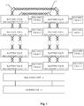
- Fig. 1 is a schematic structural diagram of a battery pack management system according to an embodiment of the present disclosure.
- the battery pack management system includes a controller 11, an isolation unit 12, a plurality of battery pack management units 13, and a plurality of battery packs 14.
- the plurality of battery packs in the battery pack management system may be connected in series, in parallel, or both in series and parallel, which is not limited herein.
- Each of the battery pack management units 13 may be used to manage a corresponding battery pack 14.
- the battery pack management unit 13 may be used to collect voltage, current, temperature, charge state, and other related parameters of the corresponding battery pack 14. The relevant parameters collected are sampled data.
- the battery pack management unit may also detect whether a communication failure of the battery pack management unit itself occurs, and detect whether the battery pack fails according to the sampled data, for example, abnormal battery pack voltage, abnormal battery pack temperature and other failures.
- the battery pack management unit 13 may be further used to receive a control instruction of the controller 11 and manage the battery pack 14 according to the control instruction.
- the first battery pack management unit 13 of the plurality of battery pack management units 13 connected in series and the last battery pack management unit 13 of the plurality of battery pack management units 13 connected in series are connected to the controller 11 through the isolation unit 12. That is to say, the two battery pack management units 13 at the first and at the end of the plurality of battery pack management units 13 connected by a first daisy chain 16 and a second daisy chain 17 are connected to the controller 11 through the isolation unit 12, so as to form a circular communication loop of the plurality of battery pack management units 13.
- the isolation unit 12 may be used to isolate high voltage and low voltage of the battery pack management units 13 and the controller 11, so as to prevent the voltage of the battery pack management units 13 and the battery packs 14 from harming the controller 11.
- the plurality of battery pack management units 13 are connected in series by the first daisy chain 16, and the plurality of battery pack management units 13 are also connected in series by the second daisy chain 17. That is to say, the plurality of battery pack management units 13 communicate through the two daisy chains.
- the first daisy chain 16 may be used to transmit the sampled data collected by the battery pack management units 13 from the corresponding battery packs 14, and transmit the control instructions of the controller 11.
- the first battery pack management unit 13 at the lower left is the battery pack management unit 13 at the first
- the first battery pack management unit 13 at the lower right is the battery pack management unit 13 at the end.
- the controller 11 may generate the control instructions and send the control instructions to the battery pack management unit 13 at the first through the isolation unit 12.
- the battery pack management unit 13 at the first sequentially transmits the control instructions to other battery pack management units 13 through the first daisy chain 16.
- the sampled data collected by each of the battery pack management units 13 from the corresponding battery pack 14 is sequentially transmitted to the controller 11 through the first daisy chain 16 and the isolation unit 12.
- the second daisy chain 17 may be used to transmit a failure prompt signal.
- the failure prompt signal may be generated by the battery pack management unit 13 that detects a failure. After the failure prompt signal is generated, the failure prompt signal is sent, starting from the battery pack management unit 13 that detects the failure, successively pass through the subsequent battery pack management units 13 to achieve the transmission in the second daisy chain 17, and is transmitted to the controller 11 through the second daisy chain 17 and the isolation unit 12. It makes the controller 11 receive the failure prompt signal quickly, so as to quickly determine that a failure of the battery pack management system occurs.
- the plurality of battery pack management units 13 are connected in series by the first daisy chain 16 and the second daisy chain 17.
- the battery pack management units 13 at the first and at the end of the plurality of battery pack management units 13 are connected to the controller 11 through the isolation unit 12, so as to form a circular communication loop of the battery pack management system.
- the first daisy chain 16 transmits the sampled data and the control instructions.
- the battery pack management unit 13 in the battery pack management system detects a failure
- the battery pack management unit 13 that detects the failure generates a failure prompt signal and transmits the failure prompt signal through the second daisy chain 17.
- the battery pack management unit 13 may detect a communication failure such as communication interruption.
- the battery pack management unit may also detect a performance failure such as abnormal voltage and abnormal temperature of the battery pack.
- the controller 11 wants to find abnormalities of the battery pack management system, it is necessary to set a detection period to periodically perform failure detection on the battery pack management units 13 in the battery pack management system. For example, the detection period is 5 minutes.
- the controller 11 may perform failure detection on the battery pack management unit every 5 minutes. However, it may occur that a failure has occurred, but there is still a certain time period from the trigger time of failure detection. Then, there is a delay for the battery pack management system to find the failure. Or, the controller 11 may collect the sampled data and determines whether the battery pack management system fails by processing the sampled data. However, it takes a certain period of time to process the sampled data, thereby causing a delay for the battery pack management system to find the failure.
- the battery pack management unit 13 that detected the failure may generate a failure prompt signal in real time, and the failure prompt signal may be quickly transmitted to the controller 11 through the second daisy chain 17 in real time. Therefore, the battery pack management system may quickly and timely find abnormalities of the battery pack management system (including various types of failures), and improve the safety and reliability of the battery pack management system.
- high voltage isolated communication can be achieved only by disposing the isolation unit 12 between the battery pack management unit 13 at the first and the controller 11, and between the battery pack management unit 13 at the end and the controller 11. It is not necessary to configure the isolation unit 12 and the controller 11 for each of the battery pack management units 13, or to configure an isolated power supply additionally. As a result, the structure of the battery pack management system can be simplified and the cost of the battery pack management system can be reduced.
- the battery pack management system in the embodiments of the present disclosure is especially suitable for scenarios with a large number of communication nodes.
- capacitors may be disposed separately between the first daisy chain 16 connecting two adjacent battery pack management units 13 and the two adjacent battery pack management units 13. That is to say, in the transmission of the sampled data or the control instructions from one battery pack management unit A1 to another adjacent battery pack management unit A2, the sampled data or the control instructions may be sent, starting from the battery pack management unit A1, sequentially pass through the capacitor between the battery pack management unit A1 and the first daisy chain 16, the first daisy chain 16, the capacitor between the first daisy chain 16 and the battery pack management unit A2, and may reach the battery pack management unit A2.
- the size and number of the capacitors may be selected according to the work scenario and work requirements, which is not limited herein.
- Disposition of the capacitors may effectively achieve isolation between high voltages in communication based on the first daisy chain 16. Moreover, the disposed capacitors may also indirectly reduce the voltage between a high voltage side and a low voltage side, and help to achieve isolation between the high voltage and the low voltage, thereby further improving the safety and reliability of the battery back management system.
- capacitors may be disposed separately between the second daisy chain 17 connecting two adjacent battery pack management units 13 and the two adjacent battery pack management units 13. That is to say, in the transmission of the failure prompt signal from one battery pack management unit A1 to another adjacent battery pack management unit A2, the failure prompt signal may be transmitted, starting from the battery pack management unit A1, sequentially pass through the capacitor between the battery pack management unit A1 and the second daisy chain 17, the second daisy chain 17, the capacitor between the second daisy chain 17 and the battery pack management unit A2, and may reach the battery pack management unit A2.
- Disposition of the capacitors may effectively achieve isolation between high voltages in the communication based on the second daisy chain 17. Moreover, the disposed capacitors may also indirectly reduce the voltage between the high voltage side and the low voltage side, and help to achieve isolation between the high voltage and the low voltage, thereby further improving the safety of the battery pack management system. Moreover, the disposed capacitors may also improve the anti-interference ability of communication transmission of the first daisy chain 16 and the second daisy chain 17. At the same time, the transmission rates of the first daisy chain 16 and the second daisy chain 17 may be custom-configured to meet various performance requirements of the battery pack management system.
- the capacitors between the two adjacent battery pack management units 13 and the first daisy chain 16 of the two adjacent battery pack management units 13 may be separately disposed.
- the capacitors between two adjacent battery pack management units 13 and the second daisy chain 17 of the two adjacent battery pack management units 13 may be separately disposed.
- both of the capacitors between two adjacent battery pack management units 13 and the first daisy chain 16 of the two adjacent battery pack management units 13, and the capacitors between two adjacent battery pack management units 13 and the second daisy chain 17 of the two adjacent battery pack management units 13 may be simultaneously disposed. This is not limited herein.
- the isolation unit 12 in the above embodiments may include a first isolation unit 121 and a second isolation unit 122.
- the first battery pack management unit 13 of the plurality of battery pack management units 13 connected in series may be connected to the controller 11 through the first isolation unit 121.
- the last battery pack management unit 13 of the plurality of battery pack management units 13 connected in series may be connected to the controller 11 through the second isolation unit 122.
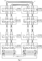
- Fig. 2 is a schematic structural diagram of a specific implementation of a battery pack management system according to an embodiment of the present disclosure.
- the battery pack management unit 13 includes a battery management chip 131.
- the battery management chip 131 may specifically be chip BQ76PL455 and other chips, which is not limited herein.
- Communication pins of the battery management chips 131 may be connected to form the first daisy chain 16, so that the plurality of battery management chips 131 are connected in series.
- the communication pins of the battery management chips 131 may include COML+, COML-, COMH+, and COMH-. Pins COML+ and COML- of the previous battery management chip 131 may be connected to pins COMH+ and COMH- of the next battery management chip 131.
- the battery management chip 131 at the first may be connected to the first isolation unit 121 through a reception pin Rx, a transmission pin Tx, a failure output pin FA N, and a wake-up pin WAKEUP.
- Failure pins of all the battery management chips 131 may be connected to form the second daisy chain 17, so that the plurality of battery management chips 131 are connected in series.
- the failure pins of the battery management chips 131 may include FAL+, FAL-, FAH+, and FAH-. Pins FAL+ and FAL- of the previous battery management chip 131 may be connected to pins FAH+ and FAH- of the next battery management chip 131.
- the battery management chip 131 at the end may be connected to the second isolation unit 122 through the reception pin Rx, the transmission pin Tx, and the failure output pin FA_N. If the battery management chip 131 fails or the battery pack monitored by the battery management chip 131 fails, the battery management chip 131 may generate a pulse signal, which is the failure prompt signal.
- the controller 11 may be provided with a first serial port and a second serial port.
- the controller 11 may be connected to the isolation unit 12 through the first serial port.
- the first serial port may be used to send the control instructions to the battery pack management units 13 through the isolation unit 12.
- the first serial port may also be used to receive the sampled data transmitted from the battery pack management unit through the isolation unit 12.
- the first serial port on the controller 11 for connecting to the first isolation unit 121 may include a reception pin Rx and a transmission pin Tx.
- the controller 11 may transmit the control instructions using the transmission pin Tx.
- the controller 11 may receive the sampled data through the reception pin Rx.
- the controller 11 may be connected to the isolation unit 12 through a second serial port.
- the second serial port may be used to receive the control instructions and/or the sampled data transmitted from the battery pack management units 13 through the isolation unit 12.
- the second serial port on the controller 11 for connecting to the second isolation unit 122 may include a reception pin Rx and a transmission pin Tx.
- the controller 11 may use the reception pin Rx of the second serial port to receive the sampled data and/or the control instructions.
- the controller 11 may transmit the control instructions through the first serial port. Or reception of the control instructions by the second serial port may indicates that the control instructions can reach each of the battery pack management units 13.
- the controller 11 may receive the sampled data through the first serial port.
- the controller 11 may also receive the sampled data through the second serial port. If the second serial port may receive the sampled data corresponding to all of the battery pack management units 13, it is indicated that the circular communication loop formed by the first daisy chain 16, the battery pack management units 13, the isolation unit 12, and the controller 11 works normally.
- the sampled data corresponding to each of the battery pack management units 13 can reach the controller 11.
- the second serial port may also perform information verification on the sampled data received by the first serial port and the sampled data received by the second serial port, and perform information verification on the control instructions sent by the first serial port and the control instructions received by the second serial port, so as to further verify the accuracy of the communication.
- the battery pack management system may fail during operation of the battery pack management system. Specifically, a communication failure may occur in the battery pack management system. For example, a single-point communication failure occurs in the first daisy chain. That is to say, a node in the circular communication loop formed by the battery pack management system is dropped, which may lead to communication interruption of the first daisy chain 16. Or, one of the two serial ports of the controller 11 may fail. The controller 11 may take a series of measures for possible failures of the battery pack management system. The details will be described below.
- the controller 11 may be used to, in the case of a single-point communication failure of the first daisy chain, configure the first serial port to send the control instructions to the battery pack management units 13 through the isolation unit 12 and to receive the sampled data transmitted from the battery pack management units 13 through the isolation unit 12, and configure the second serial port to send the control instructions to the battery pack management units 13 through the isolation unit 12 and to receive the sampled data transmitted from the battery pack management units 13 through the isolation unit 12.
- a single-point communication failure of the first daisy chain 16 in the battery pack management system is determined, which leads to abnormal communication of the first daisy chain 16.
- the controller 11 may configure the first serial port and the second serial port respectively.
- the first serial port may be used to send the control instructions to the battery pack management units 13 through the isolation unit 12.
- the circular communication loop formed by the first daisy chain 16 is broken.
- the controller 11 may configure the first serial port to receive the sampled data transmitted from the battery pack management units 13 through the isolation unit 12 in addition to sending the control instructions to the battery pack management units 13.
- the second serial port may be used to receive the control instructions and/or the sampled data transmitted from the battery pack management units 13 through the isolation unit 12.
- the circular communication loop formed by the first daisy chain 16 is broken.
- the controller 11 may configure the second serial port to send the control instructions to the battery pack management units 13 through the isolation unit 12 in addition to receiving the sampled data transmitted from the battery pack management units 13.
- the controller 11 may configure the first serial port and the second serial port, so that the first daisy chain 16 which originally formed the circular communication loop can be converted into two single-daisy-chains for communication. In this way, the communication interruption of the battery pack management system is avoided, and the reliability of the battery pack management system is improved.
- the two single-daisy-chains may each send the control instructions and receive the sampled data.
- the sampled data or the control instructions of the battery pack management units 13 in one single-daisy-chain cannot be obtained from the other corresponding serial port. Therefore, the two single-daisy-chains no longer perform information verification.
- a single-daisy-chain may include the battery pack management unit 13 at the first to the battery pack management unit 13 before the failure point of the first daisy chain 16.
- the controller 11 may manage the single-daisy-chain through the first serial port.
- the other single-daisy-chain may include the battery pack management unit 13 at the end to the battery pack management unit 13 after the failure point of the first daisy chain 16.
- the controller 11 may manage the other single-daisy-chain through the second serial port.
- the battery pack management system may include N battery pack management units 13. If a communication failure occurs in the first daisy chain 16 between the M-1th battery pack management unit 13 and the Mth battery pack management unit 13, the Mth battery pack management unit 13 to the Nth battery pack management unit 13 may be not able to receive the control instructions sent by the first serial port.
- the controller 11 may reconfigure the first and second serial ports, so that the first battery pack management unit 13 to the M-1th battery pack management unit 13 form one single-daisy-chain, and the Mth battery pack management unit 13 to the Nth battery pack management unit 13 form another single-daisy-chain.
- the communication of the battery pack management system can be maintained.
- M and N are positive integers, M ⁇ N.
- the second serial port may not receive control instructions after the first serial port sends the control instructions, which leads to failure of information verification of the second serial port on the control instructions.
- the first serial port may not receive the sampled data provided by all of the battery pack management units 13, and may only receive the sampled data provided by a part of the battery pack management units 13.
- a single-point communication failure of the first daisy chain 16 can be determined based on either of the above two situations.
- the first serial port or the second serial port of the controller 11 may also fail. If the first serial port fails, the controller 11 may reconfigure the second serial port, enabling the battery pack management system to continue communicating. Similarly, if the second serial port fails, the controller 11 may reconfigure the first serial port, enabling the battery pack management system to continue communicating.
- the controller 11 monitors that the first serial port or the second serial port cannot receive the sampled data provided by any one of the battery pack management units 13, it may be determined that the first serial port or the second serial port fails.
- the controller 11 may be configured to turn off the first serial port when the first serial port fails. That is to say, the controller 11 may control the first serial port to exit the communication link of the battery pack management system.
- the controller 11 may further be used to configure the second serial port to send the control instructions to the battery pack management units 13 through the isolation unit 12, and configure the second serial port to receive the sampled data transmitted from the battery pack management units 13 through the isolation unit 12. That is to say, in the case of failure of the first serial port, a single-daisy-chain with the second serial port performing the sending and receiving is formed in the battery pack management system. It should be noted that, in this case, the second serial port cannot obtain sampled data and/or control instructions from the first serial port, and therefore, the second serial port may not perform information verification.
- the controller 11 may be configured to turn off the second serial port when the second serial port fails. That is to say, the controller 11 may control the second serial port to exit the communication link of the battery pack management system.
- the controller 11 may further be used to configure the first serial port to send control instructions to the battery pack management units 13 through the isolation unit 12, and configure the first serial port to receive sampled data transmitted from the battery pack management units 13 through the isolation unit 12. That is to say, in the case of failure of the second serial port, a single-daisy-chain with the first serial port performing the sending and receiving is formed in the battery pack management system. It should be noted that, in this case, the first serial port cannot obtain sampled data and/or control instructions from the second serial port, and therefore, the first serial port may not perform information verification.
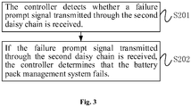
- Fig. 3 is a flowchart of a control method of a battery pack management system according to an embodiment of the present disclosure.
- the control method of the battery pack management system may be performed by a controller in the BMU.
- the control method of the battery pack management system includes steps S201 and S202.
- step S201 the controller detects whether a failure prompt signal transmitted through the second daisy chain is received.
- step S202 if the failure prompt signal transmitted through the second daisy chain is received, the controller determines that the battery pack management system fails.
- step S201 and the step S202 may be understood with reference to relevant contents of the above embodiments, and will not be repeated herein.
- the controller in the battery pack management system when the controller in the battery pack management system receives the failure prompt signal transmitted through the second daisy chain, it may be determined that the battery pack management system fails. Therefore, with the failure prompt signal transmitted through the second daisy chain, abnormalities of the battery pack management system can be found quickly and timely. As a result, the safety and reliability of the battery pack management system can be improved.
- the controller may also analyze the sampled data transmitted by the first daisy chain, and determine whether the battery pack management system fails according to the analysis results.
- the controller may also periodically send detection instructions to the battery pack management units through the first daisy chain, and detect whether the battery pack management unit fails through the detection instructions, so as to determine whether the battery pack management system fails.
- a failure prompt signal may be generated and transmitted through the second daisy chain.
- the controller may take measures to avoid damage to the battery pack management system.
- the control method of the battery pack management system described above may further include step S203 and step S204.
- step S203 if a single-point communication failure occurs in the first daisy chain, the controller configures the first serial port to send control instructions to the battery pack management units through the isolation unit, and configures the first serial port to receive sampled data transmitted from the battery group management units through the isolation unit.
- step S204 the controller configures the second serial port to send control instructions to the battery pack management units through the isolation unit, and configures the second serial port to receive sampled data transmitted from the battery pack management units through the isolation unit.
- step S203 and the step S204 may be understood with reference to relevant contents of the above embodiments, and will not be repeated herein.
- the controller may take measures to avoid communication interruption of the battery pack management system.
- the control method of the battery pack management system described above may further include step S205 or step S206.
- step S205 if the first serial port fails, the controller turns off the first serial port, and configures the second serial port to send control instructions to the battery pack management units through the isolation unit, and configures the second serial port to receive sampled data transmitted from the battery pack management units through the isolation unit.
- step S206 if the second serial port fails, the controller turns off the second serial port, and configures the first serial port to send control instructions to the battery pack management units through the isolation unit, and configures the first serial port to receive sampled data transmitted from the battery pack management units through the isolation unit.
- step S203 and the step S204 may be understood with reference to relevant contents of the above embodiments, and will not be repeated herein.
Landscapes
- Engineering & Computer Science (AREA)
- Chemical & Material Sciences (AREA)
- Chemical Kinetics & Catalysis (AREA)
- Electrochemistry (AREA)
- General Chemical & Material Sciences (AREA)
- Manufacturing & Machinery (AREA)
- Microelectronics & Electronic Packaging (AREA)
- Power Engineering (AREA)
- Charge And Discharge Circuits For Batteries Or The Like (AREA)
- Secondary Cells (AREA)
Abstract
Description
- The present disclosure relates to the field of batteries, and particularly to a battery pack management system and a control method thereof.
- With widespread application of new energy, batteries may be used as power sources in various fields. In order to ensure working safety of the batteries, it is necessary to collect and monitor performance data of the batteries.
- In practical applications, the batteries often include a plurality of battery packs. Due to individual differences of the plurality of battery packs, the performance data of each battery pack may also be different in actual work scenarios. Moreover, when one or more of the plurality of battery packs fail, the performance data of the failed battery pack is different from that of a normal battery pack. A battery management unit may identify the failed battery pack and adjust the control of the battery packs according to the performance data of the battery packs.
- However, the battery management unit needs to check the transmitted performance data of the battery packs one by one. When abnormal performance data of a certain battery pack or a certain plurality of battery packs is found, it may be determined that the battery management unit or the battery pack(s) is abnormal. That is to say, it takes a long time for the battery management unit to find the abnormalities in the battery management unit or the battery pack(s), so its timeliness is poor.
- The embodiments of the present disclosure provide a battery pack management system and a control method thereof, which may quickly and timely find abnormalities of the battery pack management system and improve the reliability of the battery pack management system.
- In a first aspect, the embodiments of the present disclosure provide a battery pack management system including a controller, an isolation unit, a plurality of battery pack management units, and a plurality of battery packs. The plurality of battery pack management units are connected in series by a first daisy chain, and the plurality of battery pack management units are also connected in series by a second daisy chain. Each of the battery pack management units is used to manage a corresponding battery pack. The first daisy chain is used to transmit sampled data which is collected by the battery pack management unit from the corresponding battery pack and transmit control instructions of the controller. The second daisy chain is used to transmit a failure prompt signal generated by a battery pack management unit that detects a failure. A first battery pack management unit of the plurality of battery pack management units connected in series and a last battery pack management unit of the plurality of battery pack management units connected in series are connected to the controller through the isolation unit.
- In a second aspect, the embodiments of the present disclosure provide a control method of a battery pack management system, which is applied to the battery pack management system in the above technical solution. The control method of the battery pack management system includes: detecting by the controller whether a failure prompt signal transmitted through the second daisy chain is received; determining, when the failure prompt signal transmitted through the second daisy chain is received, by the controller that the battery pack management system fails.
- The embodiments of the present disclosure provide a battery pack management system and a control method thereof. In the battery pack management system, a plurality of battery pack management units are connected in series by a first daisy chain and a second daisy chain. The battery pack management units at the first and at the end of the plurality of battery pack management units are connected to the controller through an isolation unit to form a circular communication loop of the battery pack management system. The first daisy chain transmits sampled data and control instructions. When a battery pack management unit or a battery pack in the battery pack management system fails, a corresponding battery pack management unit generates a failure prompt signal and transmits it through the second daisy chain. The failure prompt signal transmitted through the second daisy chain can quickly reach the controller, so that the battery pack management system can quickly and timely find abnormalities of the battery pack management system, thereby improving the reliability of the battery pack management system.
- The present disclosure can be better understood from the following description of the Detailed Description of the present disclosure with reference to the attached drawings, where the same or similar reference numbers represent the same or similar features.
-
Fig. 1 is a schematic structural diagram of a battery pack management system according to an embodiment of the present disclosure; -
Fig. 2 is a schematic structural diagram of a specific implementation of a battery pack management system according to an embodiment of the present disclosure; and -
Fig. 3 is a flowchart of a control method of a battery pack management system according to an embodiment of the present disclosure. - Various aspects of features and exemplary embodiments of the present disclosure will be described in detail below. A number of specific details are presented in the following detailed description to provide a comprehensive understanding of the present disclosure. However, it will be apparent to those skilled in the art that the present disclosure may be practiced without some of these specific details. The following description of the embodiments is merely to provide a better understanding of the present disclosure by illustrating examples thereof. The present disclosure is by no means limited to any specific configuration and algorithm set forth below, but covers any modification, replacement and improvement of elements, components and algorithms without departing from the present disclosure. Well-known structures and techniques are not shown in the drawings and the following description, so as to avoid unnecessary ambiguity of the present disclosure.
- The embodiments of the present disclosure provide a battery pack management system and a control method thereof, which may be applied in scenarios where a battery pack management unit (BMU) manages a plurality of battery packs. Each of the battery packs corresponds to a battery pack management unit. A plurality of battery pack management units may be connected in series by a daisy chain(s), and the battery pack management units at the first and at the end of the plurality of battery pack management units connected in series by the daisy chain(s) may be connected to a controller in the BMU through an isolation unit. The controller may be specified as a Microcontroller Unit (MCU). The battery pack management units may sample relevant data of the battery packs. The relevant data may include voltage, current, temperature, charge state etc., and is not limited herein. The BMU may also send control instructions, such as equalization control instructions, to each of the battery pack management units through the daisy chain(s). The battery pack management units may manage the corresponding battery packs according to the control instructions.
-
Fig. 1 is a schematic structural diagram of a battery pack management system according to an embodiment of the present disclosure. As shown inFig. 1 , the battery pack management system includes acontroller 11, anisolation unit 12, a plurality of batterypack management units 13, and a plurality ofbattery packs 14. The plurality of battery packs in the battery pack management system may be connected in series, in parallel, or both in series and parallel, which is not limited herein. - Each of the battery
pack management units 13 may be used to manage acorresponding battery pack 14. For example, the batterypack management unit 13 may be used to collect voltage, current, temperature, charge state, and other related parameters of thecorresponding battery pack 14. The relevant parameters collected are sampled data. The battery pack management unit may also detect whether a communication failure of the battery pack management unit itself occurs, and detect whether the battery pack fails according to the sampled data, for example, abnormal battery pack voltage, abnormal battery pack temperature and other failures. The batterypack management unit 13 may be further used to receive a control instruction of thecontroller 11 and manage thebattery pack 14 according to the control instruction. - The first battery
pack management unit 13 of the plurality of batterypack management units 13 connected in series and the last batterypack management unit 13 of the plurality of batterypack management units 13 connected in series are connected to thecontroller 11 through theisolation unit 12. That is to say, the two batterypack management units 13 at the first and at the end of the plurality of batterypack management units 13 connected by afirst daisy chain 16 and asecond daisy chain 17 are connected to thecontroller 11 through theisolation unit 12, so as to form a circular communication loop of the plurality of batterypack management units 13. - The
isolation unit 12 may be used to isolate high voltage and low voltage of the batterypack management units 13 and thecontroller 11, so as to prevent the voltage of the batterypack management units 13 and thebattery packs 14 from harming thecontroller 11. - The plurality of battery
pack management units 13 are connected in series by thefirst daisy chain 16, and the plurality of batterypack management units 13 are also connected in series by thesecond daisy chain 17. That is to say, the plurality of batterypack management units 13 communicate through the two daisy chains. - The
first daisy chain 16 may be used to transmit the sampled data collected by the batterypack management units 13 from thecorresponding battery packs 14, and transmit the control instructions of thecontroller 11. For example, as shown inFig. 1 , the first batterypack management unit 13 at the lower left is the batterypack management unit 13 at the first, and the first batterypack management unit 13 at the lower right is the batterypack management unit 13 at the end. Thecontroller 11 may generate the control instructions and send the control instructions to the batterypack management unit 13 at the first through theisolation unit 12. The batterypack management unit 13 at the first sequentially transmits the control instructions to other batterypack management units 13 through thefirst daisy chain 16. Similarly, the sampled data collected by each of the batterypack management units 13 from the correspondingbattery pack 14 is sequentially transmitted to thecontroller 11 through thefirst daisy chain 16 and theisolation unit 12. - The
second daisy chain 17 may be used to transmit a failure prompt signal. The failure prompt signal may be generated by the batterypack management unit 13 that detects a failure. After the failure prompt signal is generated, the failure prompt signal is sent, starting from the batterypack management unit 13 that detects the failure, successively pass through the subsequent batterypack management units 13 to achieve the transmission in thesecond daisy chain 17, and is transmitted to thecontroller 11 through thesecond daisy chain 17 and theisolation unit 12. It makes thecontroller 11 receive the failure prompt signal quickly, so as to quickly determine that a failure of the battery pack management system occurs. - In the embodiments of the present disclosure, the plurality of battery
pack management units 13 are connected in series by thefirst daisy chain 16 and thesecond daisy chain 17. The batterypack management units 13 at the first and at the end of the plurality of batterypack management units 13 are connected to thecontroller 11 through theisolation unit 12, so as to form a circular communication loop of the battery pack management system. Thefirst daisy chain 16 transmits the sampled data and the control instructions. When the batterypack management unit 13 in the battery pack management system detects a failure, the batterypack management unit 13 that detects the failure generates a failure prompt signal and transmits the failure prompt signal through thesecond daisy chain 17. The batterypack management unit 13 may detect a communication failure such as communication interruption. The battery pack management unit may also detect a performance failure such as abnormal voltage and abnormal temperature of the battery pack. - In the prior art, if the
controller 11 wants to find abnormalities of the battery pack management system, it is necessary to set a detection period to periodically perform failure detection on the batterypack management units 13 in the battery pack management system. For example, the detection period is 5 minutes. Thecontroller 11 may perform failure detection on the battery pack management unit every 5 minutes. However, it may occur that a failure has occurred, but there is still a certain time period from the trigger time of failure detection. Then, there is a delay for the battery pack management system to find the failure. Or, thecontroller 11 may collect the sampled data and determines whether the battery pack management system fails by processing the sampled data. However, it takes a certain period of time to process the sampled data, thereby causing a delay for the battery pack management system to find the failure. - Compared with the above prior art, in the embodiment of the present disclosure, the battery
pack management unit 13 that detected the failure may generate a failure prompt signal in real time, and the failure prompt signal may be quickly transmitted to thecontroller 11 through thesecond daisy chain 17 in real time. Therefore, the battery pack management system may quickly and timely find abnormalities of the battery pack management system (including various types of failures), and improve the safety and reliability of the battery pack management system. - Moreover, in the embodiments of the present disclosure, high voltage isolated communication can be achieved only by disposing the
isolation unit 12 between the batterypack management unit 13 at the first and thecontroller 11, and between the batterypack management unit 13 at the end and thecontroller 11. It is not necessary to configure theisolation unit 12 and thecontroller 11 for each of the batterypack management units 13, or to configure an isolated power supply additionally. As a result, the structure of the battery pack management system can be simplified and the cost of the battery pack management system can be reduced. The battery pack management system in the embodiments of the present disclosure is especially suitable for scenarios with a large number of communication nodes. - In some examples, capacitors may be disposed separately between the
first daisy chain 16 connecting two adjacent batterypack management units 13 and the two adjacent batterypack management units 13. That is to say, in the transmission of the sampled data or the control instructions from one battery pack management unit A1 to another adjacent battery pack management unit A2, the sampled data or the control instructions may be sent, starting from the battery pack management unit A1, sequentially pass through the capacitor between the battery pack management unit A1 and thefirst daisy chain 16, thefirst daisy chain 16, the capacitor between thefirst daisy chain 16 and the battery pack management unit A2, and may reach the battery pack management unit A2. The size and number of the capacitors may be selected according to the work scenario and work requirements, which is not limited herein. - Disposition of the capacitors may effectively achieve isolation between high voltages in communication based on the
first daisy chain 16. Moreover, the disposed capacitors may also indirectly reduce the voltage between a high voltage side and a low voltage side, and help to achieve isolation between the high voltage and the low voltage, thereby further improving the safety and reliability of the battery back management system. - In some examples, capacitors may be disposed separately between the
second daisy chain 17 connecting two adjacent batterypack management units 13 and the two adjacent batterypack management units 13. That is to say, in the transmission of the failure prompt signal from one battery pack management unit A1 to another adjacent battery pack management unit A2, the failure prompt signal may be transmitted, starting from the battery pack management unit A1, sequentially pass through the capacitor between the battery pack management unit A1 and thesecond daisy chain 17, thesecond daisy chain 17, the capacitor between thesecond daisy chain 17 and the battery pack management unit A2, and may reach the battery pack management unit A2. - Disposition of the capacitors may effectively achieve isolation between high voltages in the communication based on the
second daisy chain 17. Moreover, the disposed capacitors may also indirectly reduce the voltage between the high voltage side and the low voltage side, and help to achieve isolation between the high voltage and the low voltage, thereby further improving the safety of the battery pack management system. Moreover, the disposed capacitors may also improve the anti-interference ability of communication transmission of thefirst daisy chain 16 and thesecond daisy chain 17. At the same time, the transmission rates of thefirst daisy chain 16 and thesecond daisy chain 17 may be custom-configured to meet various performance requirements of the battery pack management system. - It should be noted that the capacitors between the two adjacent battery
pack management units 13 and thefirst daisy chain 16 of the two adjacent batterypack management units 13 may be separately disposed. Alternatively, the capacitors between two adjacent batterypack management units 13 and thesecond daisy chain 17 of the two adjacent batterypack management units 13 may be separately disposed. Alternatively, both of the capacitors between two adjacent batterypack management units 13 and thefirst daisy chain 16 of the two adjacent batterypack management units 13, and the capacitors between two adjacent batterypack management units 13 and thesecond daisy chain 17 of the two adjacent batterypack management units 13 may be simultaneously disposed. This is not limited herein. - In some examples, the
isolation unit 12 in the above embodiments may include afirst isolation unit 121 and asecond isolation unit 122. - The first battery
pack management unit 13 of the plurality of batterypack management units 13 connected in series may be connected to thecontroller 11 through thefirst isolation unit 121. The last batterypack management unit 13 of the plurality of batterypack management units 13 connected in series may be connected to thecontroller 11 through thesecond isolation unit 122. -
Fig. 2 is a schematic structural diagram of a specific implementation of a battery pack management system according to an embodiment of the present disclosure. As shown inFig. 2 , the batterypack management unit 13 includes abattery management chip 131. Thebattery management chip 131 may specifically be chip BQ76PL455 and other chips, which is not limited herein. - Communication pins of the
battery management chips 131 may be connected to form thefirst daisy chain 16, so that the plurality ofbattery management chips 131 are connected in series. As shown inFig. 2 , the communication pins of thebattery management chips 131 may include COML+, COML-, COMH+, and COMH-. Pins COML+ and COML- of the previousbattery management chip 131 may be connected to pins COMH+ and COMH- of the nextbattery management chip 131. Thebattery management chip 131 at the first may be connected to thefirst isolation unit 121 through a reception pin Rx, a transmission pin Tx, a failure output pin FA N, and a wake-up pin WAKEUP. - Failure pins of all the
battery management chips 131 may be connected to form thesecond daisy chain 17, so that the plurality ofbattery management chips 131 are connected in series. As shown inFig. 2 , the failure pins of thebattery management chips 131 may include FAL+, FAL-, FAH+, and FAH-. Pins FAL+ and FAL- of the previousbattery management chip 131 may be connected to pins FAH+ and FAH- of the nextbattery management chip 131. Thebattery management chip 131 at the end may be connected to thesecond isolation unit 122 through the reception pin Rx, the transmission pin Tx, and the failure output pin FA_N. If thebattery management chip 131 fails or the battery pack monitored by thebattery management chip 131 fails, thebattery management chip 131 may generate a pulse signal, which is the failure prompt signal. - In some examples, the
controller 11 may be provided with a first serial port and a second serial port. - The
controller 11 may be connected to theisolation unit 12 through the first serial port. The first serial port may be used to send the control instructions to the batterypack management units 13 through theisolation unit 12. The first serial port may also be used to receive the sampled data transmitted from the battery pack management unit through theisolation unit 12. For example, as shown inFig. 2 , the first serial port on thecontroller 11 for connecting to thefirst isolation unit 121 may include a reception pin Rx and a transmission pin Tx. Thecontroller 11 may transmit the control instructions using the transmission pin Tx. Thecontroller 11 may receive the sampled data through the reception pin Rx. - The
controller 11 may be connected to theisolation unit 12 through a second serial port. The second serial port may be used to receive the control instructions and/or the sampled data transmitted from the batterypack management units 13 through theisolation unit 12. For example, as shown inFig. 2 , the second serial port on thecontroller 11 for connecting to thesecond isolation unit 122 may include a reception pin Rx and a transmission pin Tx. Thecontroller 11 may use the reception pin Rx of the second serial port to receive the sampled data and/or the control instructions. - The
controller 11 may transmit the control instructions through the first serial port. Or reception of the control instructions by the second serial port may indicates that the control instructions can reach each of the batterypack management units 13. Thecontroller 11 may receive the sampled data through the first serial port. Thecontroller 11 may also receive the sampled data through the second serial port. If the second serial port may receive the sampled data corresponding to all of the batterypack management units 13, it is indicated that the circular communication loop formed by thefirst daisy chain 16, the batterypack management units 13, theisolation unit 12, and thecontroller 11 works normally. The sampled data corresponding to each of the batterypack management units 13 can reach thecontroller 11. Moreover, the second serial port may also perform information verification on the sampled data received by the first serial port and the sampled data received by the second serial port, and perform information verification on the control instructions sent by the first serial port and the control instructions received by the second serial port, so as to further verify the accuracy of the communication. - The battery pack management system may fail during operation of the battery pack management system. Specifically, a communication failure may occur in the battery pack management system. For example, a single-point communication failure occurs in the first daisy chain. That is to say, a node in the circular communication loop formed by the battery pack management system is dropped, which may lead to communication interruption of the
first daisy chain 16. Or, one of the two serial ports of thecontroller 11 may fail. Thecontroller 11 may take a series of measures for possible failures of the battery pack management system. The details will be described below. - In the above embodiments, the
controller 11 may be used to, in the case of a single-point communication failure of the first daisy chain, configure the first serial port to send the control instructions to the batterypack management units 13 through theisolation unit 12 and to receive the sampled data transmitted from the batterypack management units 13 through theisolation unit 12, and configure the second serial port to send the control instructions to the batterypack management units 13 through theisolation unit 12 and to receive the sampled data transmitted from the batterypack management units 13 through theisolation unit 12. - A single-point communication failure of the
first daisy chain 16 in the battery pack management system is determined, which leads to abnormal communication of thefirst daisy chain 16. Thecontroller 11 may configure the first serial port and the second serial port respectively. - In the case of no communication failure of the
first daisy chain 16, the first serial port may be used to send the control instructions to the batterypack management units 13 through theisolation unit 12. In the case of a single-point communication failure of thefirst daisy chain 16, the circular communication loop formed by thefirst daisy chain 16 is broken. Thecontroller 11 may configure the first serial port to receive the sampled data transmitted from the batterypack management units 13 through theisolation unit 12 in addition to sending the control instructions to the batterypack management units 13. - Similarly, in the case of no failure of the
first daisy chain 16, the second serial port may be used to receive the control instructions and/or the sampled data transmitted from the batterypack management units 13 through theisolation unit 12. In the case of a communication failure of thefirst daisy chain 16, the circular communication loop formed by thefirst daisy chain 16 is broken. Thecontroller 11 may configure the second serial port to send the control instructions to the batterypack management units 13 through theisolation unit 12 in addition to receiving the sampled data transmitted from the batterypack management units 13. - That is to say, in the case of a single-point communication failure of the
first daisy chain 16, thecontroller 11 may configure the first serial port and the second serial port, so that thefirst daisy chain 16 which originally formed the circular communication loop can be converted into two single-daisy-chains for communication. In this way, the communication interruption of the battery pack management system is avoided, and the reliability of the battery pack management system is improved. - It is worth mentioning that when the battery pack management system is converted into two single-daisy-chains for communication, since it is no longer the circular communication, the two single-daisy-chains may each send the control instructions and receive the sampled data. For either one of the single-daisy-chains, the sampled data or the control instructions of the battery
pack management units 13 in one single-daisy-chain cannot be obtained from the other corresponding serial port. Therefore, the two single-daisy-chains no longer perform information verification. - A single-daisy-chain may include the battery
pack management unit 13 at the first to the batterypack management unit 13 before the failure point of thefirst daisy chain 16. Thecontroller 11 may manage the single-daisy-chain through the first serial port. The other single-daisy-chain may include the batterypack management unit 13 at the end to the batterypack management unit 13 after the failure point of thefirst daisy chain 16. Thecontroller 11 may manage the other single-daisy-chain through the second serial port. - For example, the battery pack management system may include N battery
pack management units 13. If a communication failure occurs in thefirst daisy chain 16 between the M-1th batterypack management unit 13 and the Mth batterypack management unit 13, the Mth batterypack management unit 13 to the Nth batterypack management unit 13 may be not able to receive the control instructions sent by the first serial port. Thecontroller 11 may reconfigure the first and second serial ports, so that the first batterypack management unit 13 to the M-1th batterypack management unit 13 form one single-daisy-chain, and the Mth batterypack management unit 13 to the Nth batterypack management unit 13 form another single-daisy-chain. The communication of the battery pack management system can be maintained. M and N are positive integers, M<N.
It should be noted that the second serial port may not receive control instructions after the first serial port sends the control instructions, which leads to failure of information verification of the second serial port on the control instructions. Or, after the first serial port sends an instruction for requesting sampled data, the first serial port may not receive the sampled data provided by all of the batterypack management units 13, and may only receive the sampled data provided by a part of the batterypack management units 13. A single-point communication failure of thefirst daisy chain 16 can be determined based on either of the above two situations. - During the operation of the battery pack management system, the first serial port or the second serial port of the
controller 11 may also fail. If the first serial port fails, thecontroller 11 may reconfigure the second serial port, enabling the battery pack management system to continue communicating. Similarly, if the second serial port fails, thecontroller 11 may reconfigure the first serial port, enabling the battery pack management system to continue communicating. - It should be noted that, if the
controller 11 monitors that the first serial port or the second serial port cannot receive the sampled data provided by any one of the batterypack management units 13, it may be determined that the first serial port or the second serial port fails. - In some examples, the
controller 11 may be configured to turn off the first serial port when the first serial port fails. That is to say, thecontroller 11 may control the first serial port to exit the communication link of the battery pack management system. Thecontroller 11 may further be used to configure the second serial port to send the control instructions to the batterypack management units 13 through theisolation unit 12, and configure the second serial port to receive the sampled data transmitted from the batterypack management units 13 through theisolation unit 12. That is to say, in the case of failure of the first serial port, a single-daisy-chain with the second serial port performing the sending and receiving is formed in the battery pack management system. It should be noted that, in this case, the second serial port cannot obtain sampled data and/or control instructions from the first serial port, and therefore, the second serial port may not perform information verification. - In other examples, the
controller 11 may be configured to turn off the second serial port when the second serial port fails. That is to say, thecontroller 11 may control the second serial port to exit the communication link of the battery pack management system. Thecontroller 11 may further be used to configure the first serial port to send control instructions to the batterypack management units 13 through theisolation unit 12, and configure the first serial port to receive sampled data transmitted from the batterypack management units 13 through theisolation unit 12. That is to say, in the case of failure of the second serial port, a single-daisy-chain with the first serial port performing the sending and receiving is formed in the battery pack management system. It should be noted that, in this case, the first serial port cannot obtain sampled data and/or control instructions from the second serial port, and therefore, the first serial port may not perform information verification. -
Fig. 3 is a flowchart of a control method of a battery pack management system according to an embodiment of the present disclosure. The control method of the battery pack management system may be performed by a controller in the BMU. As shown inFig. 3 , the control method of the battery pack management system includes steps S201 and S202. - In step S201, the controller detects whether a failure prompt signal transmitted through the second daisy chain is received.
- In step S202, if the failure prompt signal transmitted through the second daisy chain is received, the controller determines that the battery pack management system fails.
- Relevant descriptions of step S201 and the step S202 may be understood with reference to relevant contents of the above embodiments, and will not be repeated herein.
- In the embodiments of the present disclosure, when the controller in the battery pack management system receives the failure prompt signal transmitted through the second daisy chain, it may be determined that the battery pack management system fails. Therefore, with the failure prompt signal transmitted through the second daisy chain, abnormalities of the battery pack management system can be found quickly and timely. As a result, the safety and reliability of the battery pack management system can be improved.
- It should be noted that the controller may also analyze the sampled data transmitted by the first daisy chain, and determine whether the battery pack management system fails according to the analysis results. The controller may also periodically send detection instructions to the battery pack management units through the first daisy chain, and detect whether the battery pack management unit fails through the detection instructions, so as to determine whether the battery pack management system fails.
- When the battery pack management unit(s) in the battery pack management system detects a failure, a failure prompt signal may be generated and transmitted through the second daisy chain. When the controller receives the failure prompt signal, the controller may take measures to avoid damage to the battery pack management system. In some examples, the control method of the battery pack management system described above may further include step S203 and step S204.
- In step S203, if a single-point communication failure occurs in the first daisy chain, the controller configures the first serial port to send control instructions to the battery pack management units through the isolation unit, and configures the first serial port to receive sampled data transmitted from the battery group management units through the isolation unit.
- In step S204, the controller configures the second serial port to send control instructions to the battery pack management units through the isolation unit, and configures the second serial port to receive sampled data transmitted from the battery pack management units through the isolation unit.
- Specifically, relevant descriptions of step S203 and the step S204 may be understood with reference to relevant contents of the above embodiments, and will not be repeated herein.
- When the first serial port or the second serial port in the battery pack management system fails, the controller may take measures to avoid communication interruption of the battery pack management system. In some examples, the control method of the battery pack management system described above may further include step S205 or step S206.
- In step S205, if the first serial port fails, the controller turns off the first serial port, and configures the second serial port to send control instructions to the battery pack management units through the isolation unit, and configures the second serial port to receive sampled data transmitted from the battery pack management units through the isolation unit.
- In step S206, if the second serial port fails, the controller turns off the second serial port, and configures the first serial port to send control instructions to the battery pack management units through the isolation unit, and configures the first serial port to receive sampled data transmitted from the battery pack management units through the isolation unit.
- Specifically, relevant descriptions of step S203 and the step S204 may be understood with reference to relevant contents of the above embodiments, and will not be repeated herein.
- Those skilled in the art shall appreciate that the foregoing embodiments are illustrative but not limiting. Different technical features appearing in different embodiments can be combined to achieve advantages. Those skilled in the art shall appreciate and implement other variant embodiments of the disclosed embodiments upon reviewing the drawings, the description and the claims. In the claims, the term "comprising" will not preclude another device(s) or step(s); the indefinite article "a/an" will not preclude plural; and the terms "first", "second", etc., are intended to designate a name but not to represent any specific order. Any reference number in the claims shall not be construed as limiting the scope of the present disclosure. Functions of a plurality of parts appearing in a claim can be performed by a separate hardware or software module. Some technical features appearing in different dependent claims will not mean that these technical features cannot be combined to achieve advantages.
- It should be clear that the various embodiments in the present specification are described in a progressive manner such that same or similar parts among embodiments may be referred to each other and each embodiment is described focusing on the differences from other embodiments. For method embodiments, relevant parts may be referred to the description of system embodiments. The present disclosure is not limited to the specific steps and structures described above and illustrated in the drawings. A person skilled in the art may make various changes, modifications and additions, or change the order of the steps after understanding the present disclosure. Also, for the purpose of concision, the detailed description of known technique is omitted herein.
Claims (10)
- A battery pack management system, characterized by comprising:
a controller (11), an isolation unit (12), a plurality of battery pack management units (13), and a plurality of battery packs (14), wherein:the plurality of battery pack management units (13) are connected in series by a first daisy chain (16), and the plurality of battery pack management units (13) are also connected in series by a second daisy chain (17), each of the battery pack management units (13) is used to manage a corresponding battery pack (14), the first daisy chain (16) is used to transmit sampled data collected by the battery pack management unit(13) from the corresponding battery pack (14) and transmit control instructions of the controller (11), the second daisy chain (17) is used to transmit a failure prompt signal which is generated by a battery pack management unit (13) that detects a failure; anda first battery pack management unit (13) of the plurality of battery pack management units (13) connected in series and a last battery pack management unit (13) of the plurality of battery pack management units (13) connected in series are connected to the controller (11) through the isolation unit (12). - The battery pack management system of claim 1, wherein:capacitors are disposed respectively between the first daisy chain (16) connecting two adjacent battery pack management units (13) and the two adjacent battery pack management units (13); and/orcapacitors are disposed respectively between the second daisy chain (17) connecting two adjacent battery pack management units (13) and the two adjacent battery pack management units (13).
- The battery pack management system of claim 1, wherein:the isolation unit (12) comprises a first isolation unit (121) and a second isolation unit (122); andthe first battery pack management unit (13) of the plurality of battery pack management units (13) connected in series is connected to the controller (11) through the first isolation unit (121), and the last battery pack management unit (13) of the plurality of battery pack management units (13) connected in series is connected to the controller (11) through the second isolation unit (122).
- The battery pack management system of claim 1, wherein:the battery pack management units (13) comprise battery management chips (131); andcommunication pins of all the battery management chips (131) are connected to form the first daisy chain (16), and failure pins of all the battery management chips (131) are connected to form the second daisy chain (17).
- The battery pack management system of claim 1, wherein:the controller (11) is connected to the isolation unit (12) through a first serial port, and the first serial port is used to send control instructions to the battery pack management units (13) through the isolation unit (12), and receive sampled data transmitted from the battery pack management units (13) through the isolation unit (12); andthe controller (11) is connected to the isolation unit (12) through a second serial port, and the second serial port is used to receive sampled data transmitted from the battery pack management units (13) and/or control instructions through the isolation unit (12).
- The battery pack management system of claim 5, wherein the controller (11) is used to, in case of a single-point communication failure of the first daisy chain (16), configure the first serial port to send the control instructions to the battery pack management units (13) through the isolation unit (12) and to receive the sampled data transmitted from the battery pack management units (13) through the isolation unit (12), and configure the second serial port to send the control instructions to the battery pack management units (13) through the isolation unit (12) and to receive the sampled data transmitted from the battery pack management units (13) through the isolation unit (12).
- The battery pack management system of claim 5, wherein:the controller (11) is used to, in case of a failure of the first serial port, turn off the first serial port and configure the second serial port to send the control instructions to the battery pack management units (13) through the isolation unit (12) and to receive the sampled data transmitted from the battery pack management units (13) through the isolation unit (12); andthe controller (11) is used to, in case of a failure of the second serial port, turn off the second serial port and configure the first serial port to send the control instructions to the battery pack management units (13) through the isolation unit (12) and to receive the sampled data transmitted from the battery pack management units (13) through the isolation unit (12).
- A control method of a battery pack management system, applied to the battery pack management system according to any one of claims 1 to 7, the method comprising:detecting (201), by the controller (11), whether the failure prompt signal transmitted through the second daisy chain (17) is received; anddetermining (202), by the controller (11), that the battery pack management system fails when the failure prompt signal transmitted through the second daisy chain (17) is received.
- The control method of claim 8, further comprising: in case of a single-point communication failure of the first daisy chain (16),
configuring, by the controller (11), a first serial port to send the control instructions to the battery pack management units (13) through the isolation unit (12) and to receive the sampled data transmitted from the battery pack management units (13) through the isolation unit (12); and
configuring, by the controller (11), a second serial port to send the control instructions to the battery pack management units (13) through the isolation unit (12) and to receive the sampled data transmitted from the battery pack management units (13) through the isolation unit (12). - The control method of a battery pack management system of claim 8, further comprising:in case of a failure of a first serial port, the controller (11) turning off the first serial port and configuring a second serial port to send the control instructions to the battery pack management units (13) through the isolation unit (12) and receive the sampled data transmitted from the battery pack management units (13) through the isolation unit (12); andin case of a failure of the second serial port, the controller (11) turning off the second serial port and configuring the first serial port to send the control instructions to the battery pack management units (13) through the isolation unit (12) and receive the sampled data transmitted from the battery pack management units (13) through the isolation unit (12).
Applications Claiming Priority (1)
| Application Number | Priority Date | Filing Date | Title |
|---|---|---|---|
| CN201810687816.4A CN110661305B (en) | 2018-06-28 | 2018-06-28 | Battery pack management system and control method thereof |
Publications (2)
| Publication Number | Publication Date |
|---|---|
| EP3588661A1 true EP3588661A1 (en) | 2020-01-01 |
| EP3588661B1 EP3588661B1 (en) | 2021-04-28 |
Family
ID=65724189
Family Applications (1)
| Application Number | Title | Priority Date | Filing Date |
|---|---|---|---|
| EP19161111.0A Active EP3588661B1 (en) | 2018-06-28 | 2019-03-06 | Battery pack management system and control method thereof |
Country Status (3)
| Country | Link |
|---|---|
| US (1) | US11031789B2 (en) |
| EP (1) | EP3588661B1 (en) |
| CN (2) | CN110661305B (en) |
Cited By (1)
| Publication number | Priority date | Publication date | Assignee | Title |
|---|---|---|---|---|
| JP2026500196A (en) * | 2023-04-18 | 2026-01-06 | 寧徳時代新能源科技股▲分▼有限公司 | Battery systems and electrical devices |
Families Citing this family (11)
| Publication number | Priority date | Publication date | Assignee | Title |
|---|---|---|---|---|
| CN111971846B (en) * | 2020-07-09 | 2022-07-08 | 东莞新能安科技有限公司 | Parallel battery pack awakening control system and method |
| CN114074576A (en) * | 2020-08-21 | 2022-02-22 | 广汽埃安新能源汽车有限公司 | Domain controlled battery management system |
| CN113709155B (en) * | 2021-08-27 | 2023-07-14 | 苏州猛禽电子科技有限公司 | Battery module daisy chain communication conversion method, system and terminal |
| CN113921921B (en) * | 2021-09-29 | 2025-03-04 | 宁德新能源科技有限公司 | Battery module protection method, BMS system, battery cluster and power consumption device |
| KR20230100211A (en) | 2021-12-28 | 2023-07-05 | 에스케이온 주식회사 | Battery system |
| CN115833875B (en) * | 2022-01-18 | 2023-11-17 | 宁德时代新能源科技股份有限公司 | Daisy chain communication fault detecting method, positioning detecting method and circuit |
| CN114755585A (en) * | 2022-04-07 | 2022-07-15 | 中国第一汽车股份有限公司 | Battery data processing method and system and vehicle |
| CN115610356A (en) * | 2022-09-16 | 2023-01-17 | 联合汽车电子有限公司 | Battery management controller and communication method for battery management controller |
| CN115291833B (en) * | 2022-10-10 | 2022-12-16 | 大唐恩智浦半导体(徐州)有限公司 | Battery management system and daisy chain communication method thereof |
| CN116846702B (en) * | 2023-05-25 | 2026-03-27 | 惠州亿纬锂能股份有限公司 | Communication control method, device, system, and storage medium based on BMS daisy chain |
| CN119493068B (en) * | 2024-12-18 | 2026-03-13 | 广东汇天航空航天科技有限公司 | Battery management system testing system, methods and flying car |
Citations (3)
| Publication number | Priority date | Publication date | Assignee | Title |
|---|---|---|---|---|
| US20100259221A1 (en) * | 2009-04-09 | 2010-10-14 | Tabatowski-Bush Ben A | Battery monitoring and control system and method of use |
| EP2693597A1 (en) * | 2011-03-31 | 2014-02-05 | Renesas Electronics Corporation | Voltage monitoring module and voltage monitoring system using same |
| EP2899556A1 (en) * | 2012-09-10 | 2015-07-29 | Renesas Electronics Corporation | Semiconductor device and battery voltage monitoring device |
Family Cites Families (26)
| Publication number | Priority date | Publication date | Assignee | Title |
|---|---|---|---|---|
| US5498950A (en) * | 1994-04-29 | 1996-03-12 | Delco Electronics Corp. | Battery monitoring, charging and balancing apparatus |
| US6822423B2 (en) * | 2001-09-03 | 2004-11-23 | Gpe International Limited | Intelligent serial battery charger and charging block |
| JP5640474B2 (en) * | 2010-06-07 | 2014-12-17 | ソニー株式会社 | Battery system |
| GB2498149B (en) * | 2010-11-25 | 2018-05-09 | Cheevc Ltd | Battery management system and method |
| JP5469625B2 (en) * | 2011-03-01 | 2014-04-16 | 株式会社日立製作所 | Battery system |
| JP5787997B2 (en) * | 2011-05-31 | 2015-09-30 | 日立オートモティブシステムズ株式会社 | Battery system monitoring device |
| US9172260B2 (en) * | 2012-05-01 | 2015-10-27 | Saroj Kumar Sahu | Efficient battery management system |
| US9263901B2 (en) * | 2012-05-19 | 2016-02-16 | Tesla Motors, Inc. | Secondary service port for high voltage battery packs |
| US9065280B2 (en) * | 2012-10-02 | 2015-06-23 | Zero Motorcycles, Inc. | System and method of using high energy battery packs |
| CN103176939B (en) * | 2013-01-16 | 2015-06-03 | 安徽工程大学 | Redundant serial communication device with automatic replacing function |
| EP3040729B1 (en) * | 2013-08-28 | 2018-01-31 | Yazaki Corporation | Battery-monitoring unit |
| CN104659852B (en) * | 2013-11-21 | 2017-02-01 | 联创汽车电子有限公司 | Battery management system of electromobile |
| CN104553852B (en) * | 2015-01-06 | 2017-02-01 | 重庆长安汽车股份有限公司 | Hybrid communication system of electric vehicle battery management system |
| US10122186B2 (en) * | 2015-09-11 | 2018-11-06 | Powin Energy Corporation | Battery management systems (BMS) having isolated, distributed, daisy-chained battery module controllers |
| CN205484533U (en) * | 2016-01-28 | 2016-08-17 | 安徽江淮汽车股份有限公司 | Battery voltage monitored control system |
| TWI581542B (en) * | 2016-03-01 | 2017-05-01 | 財團法人工業技術研究院 | Battery management system and battery system using the same |
| US10147994B2 (en) * | 2016-09-23 | 2018-12-04 | Skyworks Solutions, Inc. | Coupler circuit |
| CN206540956U (en) * | 2017-03-15 | 2017-10-03 | 安徽江淮汽车集团股份有限公司 | A kind of voltage acquisition system for battery pack framework |
| CN207117205U (en) * | 2017-04-24 | 2018-03-16 | 深圳市道通智能航空技术有限公司 | Multi-string battery group management system |
| KR102173777B1 (en) * | 2017-07-25 | 2020-11-03 | 주식회사 엘지화학 | Master battery management unit and a battery pack including the same |
| KR102173778B1 (en) * | 2017-07-25 | 2020-11-03 | 주식회사 엘지화학 | Battery management unit and a battery pack including the same |
| JP2019082399A (en) * | 2017-10-30 | 2019-05-30 | ラピスセミコンダクタ株式会社 | Battery measuring device and battery monitoring system |
| CN108001265A (en) * | 2017-11-24 | 2018-05-08 | 安徽特凯新能源科技有限公司 | A kind of battery management system equipped with serial communication detection |
| CN107770025A (en) | 2017-11-24 | 2018-03-06 | 延锋伟世通电子科技(上海)有限公司 | A kind of network device of annular differential communication |
| CN108162777A (en) * | 2017-12-19 | 2018-06-15 | 深圳市沃特玛电池有限公司 | Electric vehicle and its battery management system |
| JP7259614B2 (en) * | 2019-07-19 | 2023-04-18 | 株式会社デンソー | battery monitor |
-
2018
- 2018-06-28 CN CN201810687816.4A patent/CN110661305B/en active Active
- 2018-06-28 CN CN202011497860.2A patent/CN112564238B/en active Active
-
2019
- 2019-03-06 EP EP19161111.0A patent/EP3588661B1/en active Active
- 2019-04-12 US US16/382,778 patent/US11031789B2/en active Active
Patent Citations (3)
| Publication number | Priority date | Publication date | Assignee | Title |
|---|---|---|---|---|
| US20100259221A1 (en) * | 2009-04-09 | 2010-10-14 | Tabatowski-Bush Ben A | Battery monitoring and control system and method of use |
| EP2693597A1 (en) * | 2011-03-31 | 2014-02-05 | Renesas Electronics Corporation | Voltage monitoring module and voltage monitoring system using same |
| EP2899556A1 (en) * | 2012-09-10 | 2015-07-29 | Renesas Electronics Corporation | Semiconductor device and battery voltage monitoring device |
Cited By (2)
| Publication number | Priority date | Publication date | Assignee | Title |
|---|---|---|---|---|
| JP2026500196A (en) * | 2023-04-18 | 2026-01-06 | 寧徳時代新能源科技股▲分▼有限公司 | Battery systems and electrical devices |
| EP4697441A4 (en) * | 2023-04-18 | 2026-07-29 | Contemporary Amperex Technology Co Ltd | BATTERY SYSTEM AND ELECTRICAL DEVICE |
Also Published As
| Publication number | Publication date |
|---|---|
| US20200006955A1 (en) | 2020-01-02 |
| CN112564238A (en) | 2021-03-26 |
| CN110661305B (en) | 2021-01-05 |
| CN112564238B (en) | 2023-03-28 |
| EP3588661B1 (en) | 2021-04-28 |
| US11031789B2 (en) | 2021-06-08 |
| CN110661305A (en) | 2020-01-07 |
Similar Documents
| Publication | Publication Date | Title |
|---|---|---|
| US11031789B2 (en) | Battery pack management system and control method thereof | |
| US20100052428A1 (en) | Multi-cell battery system, and management number numbering method | |
| JP5520121B2 (en) | Battery monitoring control system and method | |
| US10024921B2 (en) | Battery management system, battery, motor vehicle having a battery management system, and method for monitoring a battery | |
| CN104238435B (en) | Triple-redundancy control computer and fault-tolerant control system | |
| US20190302191A1 (en) | System and method to reduce data handling on lithium ion battery monitors | |
| US8261129B2 (en) | Flexible bus architecture for monitoring and control of battery pack | |
| US20150028879A1 (en) | Battery management system, battery, motor vehicle having a battery management system, and method for monitoring a battery | |
| CN110703105B (en) | Battery management system | |
| US20260045567A1 (en) | Battery management system, battery, vehicle, and battery management method | |
| EP4095977B1 (en) | Slave bms for diagnosing an error of a battery module and battery pack comprising same slave bms | |
| CN101126795A (en) | Battery performance test system | |
| CN108254694B (en) | Battery working data acquisition method, system and storage medium | |
| US20210257830A1 (en) | Method, device and system for protecting parallel-connected topology units | |
| CN111983488A (en) | A battery management system and its voltage signal processing method | |
| KR102092109B1 (en) | System and method recognizing of battery module construction | |
| US20250274260A1 (en) | System and method for handling non-synchronous interrupts in a time synchronous network | |
| CN121709740A (en) | Battery management system, data processing method and energy storage device | |
| CN120669579A (en) | Vehicle-mounted control system based on dual-controller architecture | |
| CN117630675A (en) | A battery data interaction method and hybrid battery management system | |
| CN121726566A (en) | Battery information processing method, device, storage medium and program product | |
| CN121208640A (en) | A battery state testing system | |
| CN113937371A (en) | Battery management device and system |
Legal Events
| Date | Code | Title | Description |
|---|---|---|---|
| PUAI | Public reference made under article 153(3) epc to a published international application that has entered the european phase |
Free format text: ORIGINAL CODE: 0009012 |
|
| STAA | Information on the status of an ep patent application or granted ep patent |
Free format text: STATUS: THE APPLICATION HAS BEEN PUBLISHED |
|
| AK | Designated contracting states |
Kind code of ref document: A1 Designated state(s): AL AT BE BG CH CY CZ DE DK EE ES FI FR GB GR HR HU IE IS IT LI LT LU LV MC MK MT NL NO PL PT RO RS SE SI SK SM TR |
|
| AX | Request for extension of the european patent |
Extension state: BA ME |
|
| STAA | Information on the status of an ep patent application or granted ep patent |
Free format text: STATUS: REQUEST FOR EXAMINATION WAS MADE |
|
| 17P | Request for examination filed |
Effective date: 20200228 |
|
| RBV | Designated contracting states (corrected) |
Designated state(s): AL AT BE BG CH CY CZ DE DK EE ES FI FR GB GR HR HU IE IS IT LI LT LU LV MC MK MT NL NO PL PT RO RS SE SI SK SM TR |
|
| STAA | Information on the status of an ep patent application or granted ep patent |
Free format text: STATUS: EXAMINATION IS IN PROGRESS |
|
| 17Q | First examination report despatched |
Effective date: 20200723 |
|
| GRAP | Despatch of communication of intention to grant a patent |
Free format text: ORIGINAL CODE: EPIDOSNIGR1 |
|
| STAA | Information on the status of an ep patent application or granted ep patent |
Free format text: STATUS: GRANT OF PATENT IS INTENDED |
|
| INTG | Intention to grant announced |
Effective date: 20210216 |
|
| GRAS | Grant fee paid |
Free format text: ORIGINAL CODE: EPIDOSNIGR3 |
|
| GRAA | (expected) grant |
Free format text: ORIGINAL CODE: 0009210 |
|
| STAA | Information on the status of an ep patent application or granted ep patent |
Free format text: STATUS: THE PATENT HAS BEEN GRANTED |
|
| AK | Designated contracting states |
Kind code of ref document: B1 Designated state(s): AL AT BE BG CH CY CZ DE DK EE ES FI FR GB GR HR HU IE IS IT LI LT LU LV MC MK MT NL NO PL PT RO RS SE SI SK SM TR |
|
| REG | Reference to a national code |
Ref country code: GB Ref legal event code: FG4D |
|
| REG | Reference to a national code |
Ref country code: CH Ref legal event code: EP |
|
| REG | Reference to a national code |
Ref country code: AT Ref legal event code: REF Ref document number: 1388147 Country of ref document: AT Kind code of ref document: T Effective date: 20210515 |
|
| REG | Reference to a national code |
Ref country code: DE Ref legal event code: R096 Ref document number: 602019004128 Country of ref document: DE |
|
| REG | Reference to a national code |
Ref country code: IE Ref legal event code: FG4D |
|
| REG | Reference to a national code |
Ref country code: LT Ref legal event code: MG9D |
|
| REG | Reference to a national code |
Ref country code: AT Ref legal event code: MK05 Ref document number: 1388147 Country of ref document: AT Kind code of ref document: T Effective date: 20210428 |
|
| PG25 | Lapsed in a contracting state [announced via postgrant information from national office to epo] |
Ref country code: NL Free format text: LAPSE BECAUSE OF FAILURE TO SUBMIT A TRANSLATION OF THE DESCRIPTION OR TO PAY THE FEE WITHIN THE PRESCRIBED TIME-LIMIT Effective date: 20210428 Ref country code: BG Free format text: LAPSE BECAUSE OF FAILURE TO SUBMIT A TRANSLATION OF THE DESCRIPTION OR TO PAY THE FEE WITHIN THE PRESCRIBED TIME-LIMIT Effective date: 20210728 Ref country code: AT Free format text: LAPSE BECAUSE OF FAILURE TO SUBMIT A TRANSLATION OF THE DESCRIPTION OR TO PAY THE FEE WITHIN THE PRESCRIBED TIME-LIMIT Effective date: 20210428 Ref country code: FI Free format text: LAPSE BECAUSE OF FAILURE TO SUBMIT A TRANSLATION OF THE DESCRIPTION OR TO PAY THE FEE WITHIN THE PRESCRIBED TIME-LIMIT Effective date: 20210428 Ref country code: HR Free format text: LAPSE BECAUSE OF FAILURE TO SUBMIT A TRANSLATION OF THE DESCRIPTION OR TO PAY THE FEE WITHIN THE PRESCRIBED TIME-LIMIT Effective date: 20210428 Ref country code: LT Free format text: LAPSE BECAUSE OF FAILURE TO SUBMIT A TRANSLATION OF THE DESCRIPTION OR TO PAY THE FEE WITHIN THE PRESCRIBED TIME-LIMIT Effective date: 20210428 |
|
| PG25 | Lapsed in a contracting state [announced via postgrant information from national office to epo] |
Ref country code: IS Free format text: LAPSE BECAUSE OF FAILURE TO SUBMIT A TRANSLATION OF THE DESCRIPTION OR TO PAY THE FEE WITHIN THE PRESCRIBED TIME-LIMIT Effective date: 20210828 Ref country code: GR Free format text: LAPSE BECAUSE OF FAILURE TO SUBMIT A TRANSLATION OF THE DESCRIPTION OR TO PAY THE FEE WITHIN THE PRESCRIBED TIME-LIMIT Effective date: 20210729 Ref country code: PL Free format text: LAPSE BECAUSE OF FAILURE TO SUBMIT A TRANSLATION OF THE DESCRIPTION OR TO PAY THE FEE WITHIN THE PRESCRIBED TIME-LIMIT Effective date: 20210428 Ref country code: NO Free format text: LAPSE BECAUSE OF FAILURE TO SUBMIT A TRANSLATION OF THE DESCRIPTION OR TO PAY THE FEE WITHIN THE PRESCRIBED TIME-LIMIT Effective date: 20210728 Ref country code: LV Free format text: LAPSE BECAUSE OF FAILURE TO SUBMIT A TRANSLATION OF THE DESCRIPTION OR TO PAY THE FEE WITHIN THE PRESCRIBED TIME-LIMIT Effective date: 20210428 Ref country code: PT Free format text: LAPSE BECAUSE OF FAILURE TO SUBMIT A TRANSLATION OF THE DESCRIPTION OR TO PAY THE FEE WITHIN THE PRESCRIBED TIME-LIMIT Effective date: 20210830 Ref country code: SE Free format text: LAPSE BECAUSE OF FAILURE TO SUBMIT A TRANSLATION OF THE DESCRIPTION OR TO PAY THE FEE WITHIN THE PRESCRIBED TIME-LIMIT Effective date: 20210428 Ref country code: RS Free format text: LAPSE BECAUSE OF FAILURE TO SUBMIT A TRANSLATION OF THE DESCRIPTION OR TO PAY THE FEE WITHIN THE PRESCRIBED TIME-LIMIT Effective date: 20210428 |
|
| REG | Reference to a national code |
Ref country code: NL Ref legal event code: MP Effective date: 20210428 |
|
| PG25 | Lapsed in a contracting state [announced via postgrant information from national office to epo] |
Ref country code: ES Free format text: LAPSE BECAUSE OF FAILURE TO SUBMIT A TRANSLATION OF THE DESCRIPTION OR TO PAY THE FEE WITHIN THE PRESCRIBED TIME-LIMIT Effective date: 20210428 Ref country code: EE Free format text: LAPSE BECAUSE OF FAILURE TO SUBMIT A TRANSLATION OF THE DESCRIPTION OR TO PAY THE FEE WITHIN THE PRESCRIBED TIME-LIMIT Effective date: 20210428 Ref country code: SK Free format text: LAPSE BECAUSE OF FAILURE TO SUBMIT A TRANSLATION OF THE DESCRIPTION OR TO PAY THE FEE WITHIN THE PRESCRIBED TIME-LIMIT Effective date: 20210428 Ref country code: SM Free format text: LAPSE BECAUSE OF FAILURE TO SUBMIT A TRANSLATION OF THE DESCRIPTION OR TO PAY THE FEE WITHIN THE PRESCRIBED TIME-LIMIT Effective date: 20210428 Ref country code: RO Free format text: LAPSE BECAUSE OF FAILURE TO SUBMIT A TRANSLATION OF THE DESCRIPTION OR TO PAY THE FEE WITHIN THE PRESCRIBED TIME-LIMIT Effective date: 20210428 Ref country code: DK Free format text: LAPSE BECAUSE OF FAILURE TO SUBMIT A TRANSLATION OF THE DESCRIPTION OR TO PAY THE FEE WITHIN THE PRESCRIBED TIME-LIMIT Effective date: 20210428 Ref country code: CZ Free format text: LAPSE BECAUSE OF FAILURE TO SUBMIT A TRANSLATION OF THE DESCRIPTION OR TO PAY THE FEE WITHIN THE PRESCRIBED TIME-LIMIT Effective date: 20210428 |
|
| REG | Reference to a national code |
Ref country code: DE Ref legal event code: R097 Ref document number: 602019004128 Country of ref document: DE |
|
| PLBE | No opposition filed within time limit |
Free format text: ORIGINAL CODE: 0009261 |
|
| STAA | Information on the status of an ep patent application or granted ep patent |
Free format text: STATUS: NO OPPOSITION FILED WITHIN TIME LIMIT |
|
| 26N | No opposition filed |
Effective date: 20220131 |
|
| REG | Reference to a national code |
Ref country code: GB Ref legal event code: 732E Free format text: REGISTERED BETWEEN 20220407 AND 20220413 |
|
| PG25 | Lapsed in a contracting state [announced via postgrant information from national office to epo] |
Ref country code: IS Free format text: LAPSE BECAUSE OF FAILURE TO SUBMIT A TRANSLATION OF THE DESCRIPTION OR TO PAY THE FEE WITHIN THE PRESCRIBED TIME-LIMIT Effective date: 20210828 Ref country code: AL Free format text: LAPSE BECAUSE OF FAILURE TO SUBMIT A TRANSLATION OF THE DESCRIPTION OR TO PAY THE FEE WITHIN THE PRESCRIBED TIME-LIMIT Effective date: 20210428 |
|
| REG | Reference to a national code |
Ref country code: DE Ref legal event code: R081 Ref document number: 602019004128 Country of ref document: DE Owner name: CONTEMPORARY AMPEREX RUNZHI SOFTWARE TECHNOLOG, CN Free format text: FORMER OWNER: CONTEMPORARY AMPEREX TECHNOLOGY CO., LTD., NINGDE CITY, FUJIAN, CN |
|
| PG25 | Lapsed in a contracting state [announced via postgrant information from national office to epo] |
Ref country code: IT Free format text: LAPSE BECAUSE OF FAILURE TO SUBMIT A TRANSLATION OF THE DESCRIPTION OR TO PAY THE FEE WITHIN THE PRESCRIBED TIME-LIMIT Effective date: 20210428 |
|
| PG25 | Lapsed in a contracting state [announced via postgrant information from national office to epo] |
Ref country code: MC Free format text: LAPSE BECAUSE OF FAILURE TO SUBMIT A TRANSLATION OF THE DESCRIPTION OR TO PAY THE FEE WITHIN THE PRESCRIBED TIME-LIMIT Effective date: 20210428 |
|
| REG | Reference to a national code |
Ref country code: CH Ref legal event code: PL |
|
| REG | Reference to a national code |
Ref country code: BE Ref legal event code: MM Effective date: 20220331 |
|
| PG25 | Lapsed in a contracting state [announced via postgrant information from national office to epo] |
Ref country code: LU Free format text: LAPSE BECAUSE OF NON-PAYMENT OF DUE FEES Effective date: 20220306 Ref country code: LI Free format text: LAPSE BECAUSE OF NON-PAYMENT OF DUE FEES Effective date: 20220331 Ref country code: IE Free format text: LAPSE BECAUSE OF NON-PAYMENT OF DUE FEES Effective date: 20220306 Ref country code: CH Free format text: LAPSE BECAUSE OF NON-PAYMENT OF DUE FEES Effective date: 20220331 |
|
| PG25 | Lapsed in a contracting state [announced via postgrant information from national office to epo] |
Ref country code: BE Free format text: LAPSE BECAUSE OF NON-PAYMENT OF DUE FEES Effective date: 20220331 |
|
| P01 | Opt-out of the competence of the unified patent court (upc) registered |
Effective date: 20230516 |
|
| PG25 | Lapsed in a contracting state [announced via postgrant information from national office to epo] |
Ref country code: MK Free format text: LAPSE BECAUSE OF FAILURE TO SUBMIT A TRANSLATION OF THE DESCRIPTION OR TO PAY THE FEE WITHIN THE PRESCRIBED TIME-LIMIT Effective date: 20210428 Ref country code: CY Free format text: LAPSE BECAUSE OF FAILURE TO SUBMIT A TRANSLATION OF THE DESCRIPTION OR TO PAY THE FEE WITHIN THE PRESCRIBED TIME-LIMIT Effective date: 20210428 |
|
| PG25 | Lapsed in a contracting state [announced via postgrant information from national office to epo] |
Ref country code: HU Free format text: LAPSE BECAUSE OF FAILURE TO SUBMIT A TRANSLATION OF THE DESCRIPTION OR TO PAY THE FEE WITHIN THE PRESCRIBED TIME-LIMIT; INVALID AB INITIO Effective date: 20190306 |
|
| PG25 | Lapsed in a contracting state [announced via postgrant information from national office to epo] |
Ref country code: MT Free format text: LAPSE BECAUSE OF FAILURE TO SUBMIT A TRANSLATION OF THE DESCRIPTION OR TO PAY THE FEE WITHIN THE PRESCRIBED TIME-LIMIT Effective date: 20210428 |
|
| PG25 | Lapsed in a contracting state [announced via postgrant information from national office to epo] |
Ref country code: TR Free format text: LAPSE BECAUSE OF FAILURE TO SUBMIT A TRANSLATION OF THE DESCRIPTION OR TO PAY THE FEE WITHIN THE PRESCRIBED TIME-LIMIT Effective date: 20210428 |
|
| PGFP | Annual fee paid to national office [announced via postgrant information from national office to epo] |
Ref country code: FR Payment date: 20251231 Year of fee payment: 8 |
|
| PGFP | Annual fee paid to national office [announced via postgrant information from national office to epo] |
Ref country code: GB Payment date: 20260106 Year of fee payment: 8 |
|
| PGFP | Annual fee paid to national office [announced via postgrant information from national office to epo] |
Ref country code: DE Payment date: 20260102 Year of fee payment: 8 |