EP3588254A1 - Information processing device, method, and program - Google Patents
Information processing device, method, and program Download PDFInfo
- Publication number
- EP3588254A1 EP3588254A1 EP17898053.8A EP17898053A EP3588254A1 EP 3588254 A1 EP3588254 A1 EP 3588254A1 EP 17898053 A EP17898053 A EP 17898053A EP 3588254 A1 EP3588254 A1 EP 3588254A1
- Authority
- EP
- European Patent Office
- Prior art keywords
- information processing
- processing apparatus
- control unit
- background object
- display control
- Prior art date
- Legal status (The legal status is an assumption and is not a legal conclusion. Google has not performed a legal analysis and makes no representation as to the accuracy of the status listed.)
- Granted
Links
Images





Classifications
-
- G—PHYSICS
- G06—COMPUTING OR CALCULATING; COUNTING
- G06F—ELECTRIC DIGITAL DATA PROCESSING
- G06F1/00—Details not covered by groups G06F3/00 - G06F13/00 and G06F21/00
- G06F1/16—Constructional details or arrangements
- G06F1/1613—Constructional details or arrangements for portable computers
- G06F1/1633—Constructional details or arrangements of portable computers not specific to the type of enclosures covered by groups G06F1/1615 - G06F1/1626
- G06F1/1637—Details related to the display arrangement, including those related to the mounting of the display in the housing
- G06F1/1643—Details related to the display arrangement, including those related to the mounting of the display in the housing the display being associated to a digitizer, e.g. laptops that can be used as penpads
-
- G—PHYSICS
- G06—COMPUTING OR CALCULATING; COUNTING
- G06F—ELECTRIC DIGITAL DATA PROCESSING
- G06F3/00—Input arrangements for transferring data to be processed into a form capable of being handled by the computer; Output arrangements for transferring data from processing unit to output unit, e.g. interface arrangements
- G06F3/01—Input arrangements or combined input and output arrangements for interaction between user and computer
- G06F3/048—Interaction techniques based on graphical user interfaces [GUI]
- G06F3/0481—Interaction techniques based on graphical user interfaces [GUI] based on specific properties of the displayed interaction object or a metaphor-based environment, e.g. interaction with desktop elements like windows or icons, or assisted by a cursor's changing behaviour or appearance
- G06F3/04817—Interaction techniques based on graphical user interfaces [GUI] based on specific properties of the displayed interaction object or a metaphor-based environment, e.g. interaction with desktop elements like windows or icons, or assisted by a cursor's changing behaviour or appearance using icons
-
- G—PHYSICS
- G06—COMPUTING OR CALCULATING; COUNTING
- G06F—ELECTRIC DIGITAL DATA PROCESSING
- G06F1/00—Details not covered by groups G06F3/00 - G06F13/00 and G06F21/00
- G06F1/26—Power supply means, e.g. regulation thereof
- G06F1/32—Means for saving power
- G06F1/3203—Power management, i.e. event-based initiation of a power-saving mode
- G06F1/3206—Monitoring of events, devices or parameters that trigger a change in power modality
- G06F1/3215—Monitoring of peripheral devices
-
- G—PHYSICS
- G06—COMPUTING OR CALCULATING; COUNTING
- G06F—ELECTRIC DIGITAL DATA PROCESSING
- G06F1/00—Details not covered by groups G06F3/00 - G06F13/00 and G06F21/00
- G06F1/26—Power supply means, e.g. regulation thereof
- G06F1/32—Means for saving power
- G06F1/3203—Power management, i.e. event-based initiation of a power-saving mode
- G06F1/3234—Power saving characterised by the action undertaken
- G06F1/325—Power saving in peripheral device
- G06F1/3262—Power saving in digitizer or tablet
-
- G—PHYSICS
- G06—COMPUTING OR CALCULATING; COUNTING
- G06F—ELECTRIC DIGITAL DATA PROCESSING
- G06F1/00—Details not covered by groups G06F3/00 - G06F13/00 and G06F21/00
- G06F1/26—Power supply means, e.g. regulation thereof
- G06F1/32—Means for saving power
- G06F1/3203—Power management, i.e. event-based initiation of a power-saving mode
- G06F1/3234—Power saving characterised by the action undertaken
- G06F1/325—Power saving in peripheral device
- G06F1/3265—Power saving in display device
-
- G—PHYSICS
- G06—COMPUTING OR CALCULATING; COUNTING
- G06F—ELECTRIC DIGITAL DATA PROCESSING
- G06F3/00—Input arrangements for transferring data to be processed into a form capable of being handled by the computer; Output arrangements for transferring data from processing unit to output unit, e.g. interface arrangements
- G06F3/01—Input arrangements or combined input and output arrangements for interaction between user and computer
- G06F3/048—Interaction techniques based on graphical user interfaces [GUI]
- G06F3/0481—Interaction techniques based on graphical user interfaces [GUI] based on specific properties of the displayed interaction object or a metaphor-based environment, e.g. interaction with desktop elements like windows or icons, or assisted by a cursor's changing behaviour or appearance
-
- G—PHYSICS
- G06—COMPUTING OR CALCULATING; COUNTING
- G06F—ELECTRIC DIGITAL DATA PROCESSING
- G06F3/00—Input arrangements for transferring data to be processed into a form capable of being handled by the computer; Output arrangements for transferring data from processing unit to output unit, e.g. interface arrangements
- G06F3/01—Input arrangements or combined input and output arrangements for interaction between user and computer
- G06F3/048—Interaction techniques based on graphical user interfaces [GUI]
- G06F3/0481—Interaction techniques based on graphical user interfaces [GUI] based on specific properties of the displayed interaction object or a metaphor-based environment, e.g. interaction with desktop elements like windows or icons, or assisted by a cursor's changing behaviour or appearance
- G06F3/0482—Interaction with lists of selectable items, e.g. menus
-
- G—PHYSICS
- G06—COMPUTING OR CALCULATING; COUNTING
- G06F—ELECTRIC DIGITAL DATA PROCESSING
- G06F3/00—Input arrangements for transferring data to be processed into a form capable of being handled by the computer; Output arrangements for transferring data from processing unit to output unit, e.g. interface arrangements
- G06F3/01—Input arrangements or combined input and output arrangements for interaction between user and computer
- G06F3/048—Interaction techniques based on graphical user interfaces [GUI]
- G06F3/0484—Interaction techniques based on graphical user interfaces [GUI] for the control of specific functions or operations, e.g. selecting or manipulating an object, an image or a displayed text element, setting a parameter value or selecting a range
- G06F3/04842—Selection of displayed objects or displayed text elements
-
- G—PHYSICS
- G06—COMPUTING OR CALCULATING; COUNTING
- G06F—ELECTRIC DIGITAL DATA PROCESSING
- G06F3/00—Input arrangements for transferring data to be processed into a form capable of being handled by the computer; Output arrangements for transferring data from processing unit to output unit, e.g. interface arrangements
- G06F3/01—Input arrangements or combined input and output arrangements for interaction between user and computer
- G06F3/048—Interaction techniques based on graphical user interfaces [GUI]
- G06F3/0487—Interaction techniques based on graphical user interfaces [GUI] using specific features provided by the input device, e.g. functions controlled by the rotation of a mouse with dual sensing arrangements, or of the nature of the input device, e.g. tap gestures based on pressure sensed by a digitiser
- G06F3/0488—Interaction techniques based on graphical user interfaces [GUI] using specific features provided by the input device, e.g. functions controlled by the rotation of a mouse with dual sensing arrangements, or of the nature of the input device, e.g. tap gestures based on pressure sensed by a digitiser using a touch-screen or digitiser, e.g. input of commands through traced gestures
- G06F3/04883—Interaction techniques based on graphical user interfaces [GUI] using specific features provided by the input device, e.g. functions controlled by the rotation of a mouse with dual sensing arrangements, or of the nature of the input device, e.g. tap gestures based on pressure sensed by a digitiser using a touch-screen or digitiser, e.g. input of commands through traced gestures for inputting data by handwriting, e.g. gesture or text
-
- Y—GENERAL TAGGING OF NEW TECHNOLOGICAL DEVELOPMENTS; GENERAL TAGGING OF CROSS-SECTIONAL TECHNOLOGIES SPANNING OVER SEVERAL SECTIONS OF THE IPC; TECHNICAL SUBJECTS COVERED BY FORMER USPC CROSS-REFERENCE ART COLLECTIONS [XRACs] AND DIGESTS
- Y02—TECHNOLOGIES OR APPLICATIONS FOR MITIGATION OR ADAPTATION AGAINST CLIMATE CHANGE
- Y02D—CLIMATE CHANGE MITIGATION TECHNOLOGIES IN INFORMATION AND COMMUNICATION TECHNOLOGIES [ICT], I.E. INFORMATION AND COMMUNICATION TECHNOLOGIES AIMING AT THE REDUCTION OF THEIR OWN ENERGY USE
- Y02D10/00—Energy efficient computing, e.g. low power processors, power management or thermal management
Definitions
- the present disclosure relates to an information processing apparatus, method, and program.
- a display screen of an information processing apparatus generally includes display that directly indicates a state of the information processing apparatus, such as a battery-shaped indicator indicating a remaining battery capacity and an antenna-shaped indicator indicating a radio wave reception environment. Display control in an information processing apparatus is disclosed, for example, in Patent Document 1.
- Patent Document 1 Japanese Patent Application Laid-Open No. 2011-141825
- the present disclosure proposes a new and improved information processing apparatus, method, and program, capable of indirectly expressing a state change of an information processing apparatus.
- an information processing apparatus which includes a display control unit that generates a display screen including a background object, and the display control unit moves the background object in accordance with a state change of the information processing apparatus.
- a method which is performed by an information processing apparatus including generating a display screen including a background object by a processor and moving the background object according to a state change of the information processing apparatus.
- a program for causing a computer to function as an information processing apparatus including a display control unit for generating a display screen including a background object, the display control unit moving the background object in accordance with a state change of the information processing apparatus.
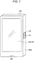
- Fig. 1 is a view illustrating an appearance of a terminal device 100 of the present disclosure.
- the terminal device 100 may be a smartphone.
- a display unit 120 and a touch panel 130 are disposed on a front surface of a housing.
- a fingerprint reader 170 and a power button 141 are disposed on a side surface 100S of the housing.
- the power button 141 is disposed below the fingerprint reader 170.
- the fingerprint reader 170 is pressed, the power button 141 disposed below the fingerprint reader 170 is pressed, and the power of the terminal device 100 is turned on.
- the state of the terminal device 100 is switched from a sleep state to a state in which a lock screen is displayed on the display unit 120 by pressing the power button 141. Note that, on the lock screen, functions that a user can execute on the terminal device 100 are limited.
- a user can perform a fingerprint image registration operation and a collation operation by bringing a finger into contact with the fingerprint reader 170 disposed on the power button 141.
- the operation of a finger for causing the fingerprint reader 170 to read a fingerprint can be divided into a touch operation and a push operation.
- the touch operation is an operation in which a finger touches a detection surface of the fingerprint reader 170.
- a force with which a finger presses the detection surface is weaker than the push operation as described later.
- the fingerprint reader 170 reads a fingerprint image (hereinafter also referred to as a "fingerprint image") in a state where the power button 141 is not pressed.
- Registration of a fingerprint may be performed by the touch operation. Since it is easy for a user to operate the touch operation, the user can relatively easily perform the fingerprint registration process or the fingerprint authentication process a plurality of times. When a fingerprint is initially registered on the terminal device 100, there is a possibility that a user may register a fingerprint a plurality of times. Therefore, the user can perform fingerprint registration relatively easily by performing the fingerprint registration process by touch operation. Note that, in the fingerprint registration process, the features of a fingerprint image read by the touch operation are registered.
- the push operation is an operation to press a detection surface of the fingerprint reader 170 in reading a fingerprint.
- the force with which a finger presses the detection surface is stronger than the force in the touch operation.
- the fingerprint reader 170 reads a fingerprint image in a state where the power button 141 is pressed by the fingerprint reader 170.
- the user cancels a sleep state and puts the terminal device 100 in a state where a fingerprint authentication process can be activated.
- the user presses the power button 141 via the fingerprint reader 170 to start fingerprint authentication.
- the terminal device 100 is ready to start fingerprint authentication.
- the authentication is performed by collating the feature of the fingerprint image read by the push operation with the feature of the registered fingerprint image.
- turn-on of the power or the cancellation of a sleep state and the start of fingerprint authentication may be simultaneously performed by the push operation. Therefore, the user can perform, for example, the cancellation of a sleep state and the fingerprint authentication by one operation.
- the lock or sleep state of the terminal device 100 may be canceled by operating an operation key other than the power button 141.
- the power button 141 may not be disposed, and the fingerprint reader 170 may directly press the power switch.
- connection terminal 190 to which a cable is connected is disposed.
- a data communication cable for communicating data with an external device, or a power supply cable for supplying power may be connected to the connection terminal 190.
- Such a connection terminal 190 may be, for example, a USB port.
- the terminal device 100 is not limited to a smart phone.
- the terminal device 100 may be an information processing apparatus such as a personal computer (PC), a home video processor (DVD recorder, video deck, etc.), a personal digital assistants (PDA), a home gaming device, a home appliance, a mobile phone, a portable music playback device, a portable video processor, and a portable game apparatus.
- PC personal computer
- DVD recorder DVD recorder
- video deck etc.
- PDA personal digital assistants
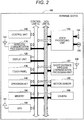
- Fig. 2 is an explanatory view illustrating a functional configuration of the terminal device 100.
- the terminal device 100 includes a control unit 160, a wireless communication processing unit 110, a display unit 120, a touch panel 130, an operation key 140, a memory 150, and a GPS unit 180.
- the terminal device 100 further includes a voice processing unit 103, a speaker 104, a microphone 105, a short distance wireless communication processing unit 107, a motion sensor 108, a camera 109, and antennas 101, 106, and 181.
- the control unit 160 transmits a control command to the wireless communication processing unit 110 via a control line CL. Furthermore, the control unit 160 also reads a program (software) stored in the memory 150 via the control line CL. Then, the control unit 160 controls each part of the terminal device 100 by executing the read program. The control unit 160 also executes a fingerprint authentication program stored in the memory 150 to perform fingerprint registration processing and authentication processing.
- the control unit 160 may have functions of a feature extraction unit that extracts features of a fingerprint and a collating unit that performs collating of the fingerprint.
- the control unit 160 includes, for example, a central processing unit (CPU). Note that, the control unit 160 may have a function of a detection unit that detects that authentication processing has been started.
- control unit 160 may have a function of a display control unit for displaying a lock screen, an authentication processing screen, and a home screen as described later.
- Display elements generated by the display control unit include a UI used for operation, a character string, an image (moving image, still image), a window, an icon, a background object, and the like.
- the wireless communication processing unit 110 performs processing of transmission and reception of a wireless signal under the control of the control unit 160. Furthermore, the terminal device 100 further includes the antenna 101 for performing wireless communication with a base station, and the antenna 101 is connected to the wireless communication processing unit 110.
- the wireless communication processing unit 110 may perform transmission/reception processing under the control of the control unit 160.
- the data received by the wireless communication processing unit 110 is stored in the memory 150, and the control of the control unit 160 performs processing such as display based on the stored data.
- the data stored in the memory 150 is supplied to the wireless communication processing unit 110 and transmitted wirelessly.
- the memory 150 stores data prepared in advance, such as a program, and stores data generated by a user operation. Storage of data in the memory 150 and reading of data from the memory 150 are performed under the control of the control unit 160.
- the voice processing unit 103 demodulates supplied voice data to obtain an analog voice signal.
- the voice data supplied to the voice processing unit 103 may be voice data for a call received by the wireless communication processing unit 110.
- the wireless communication processing unit 110 supplies voice data to the voice processing unit 103 via a data line DL.
- the analog voice signal obtained by the voice processing unit 103 is supplied to the speaker 104, and voice is output from the speaker 104.
- the voice processing unit 103 converts a voice signal output from the microphone 105 into voice data of a transmission format. Then, the voice data converted by the voice processing unit 103 is supplied to the wireless communication processing unit 110 via the data line DL. Furthermore, the voice data supplied to the wireless communication processing unit 110 is packetized and wirelessly transmitted.
- the voice processing unit 103, the speaker 104, and the microphone 105 may be omitted.
- the display unit 120 displays various display screens such as a lock screen, an authentication processing screen, and a home screen on the display panel under the control of the control unit 160.
- a display panel for example, a liquid crystal display panel or an organic electro-luminescence (EL) display panel is used.
- the touch panel 130 detects a touched position when the surface (detection surface) of the display panel is touched with an object such as a finger or a pen. For example, the touch panel 130 detects that a finger or a pen has contacted with an area or the like in which the display panel displays an image or the like. Note that, the touch panel 130 may be stacked on the display panel or may be integrated with the display panel. The touch panel 130 may be, for example, a capacitance type. In this case, the touch panel 130 detects that the surface of the display panel is touched with a finger or the like from a change in capacitance.
- Data on the touch position detected by the touch panel 130 is transmitted to the control unit 160.
- the control unit 160 executes an application being activated on the basis of the supplied touch position.
- the touch position is indicated by coordinate positions of, for example, an X axis (horizontal axis) and a Y axis (vertical axis) which are two orthogonal axes.
- the coordinate position detected by the touch panel 130 is not limited to one point. In a case where a plurality of points is simultaneously touched, the control unit 160 performs control based on a plurality of the points detected. Furthermore, when a wide range of the touch panel 130 is touched simultaneously, the control unit 160 detects the entire touched range.
- the terminal device 100 further includes the operation key 140 such as a power switch 142. Operation information of the operation key 140 is transmitted to the control unit 160.
- the surface of the operation key 140 may be provided with a fingerprint reader 170 that reads the surface (fingerprint) of a placed finger.
- the fingerprint reader 170 may read a fingerprint of a finger having touched the detection surface disposed on its surface and may send the read image to the control unit 160. Further, the fingerprint reader 170 stores the read image in the memory 150.
- the fingerprint reader 170 includes a plurality of sensor elements disposed in a two-dimensional array. For the fingerprint reader 170, for example, an optical method, an electric field strength measurement method, a capacitance method, or the like is used.
- the GPS unit 180 acquires the position of the terminal device 100 by performing triangulation on the basis of information included in radio waves received from satellites.
- the GPS unit 180 is connected to an antenna 181 for receiving radio waves from satellites.
- the short distance wireless communication processing unit 107 is used to perform short distance wireless communication with another terminal.
- the short distance wireless communication method may be, for example, Wi-Fi, Bluetooth (registered trademark), or Zigbee (registered trademark).
- the short distance wireless communication processing unit 107 is connected to the antenna 106 for transmitting radio waves to another terminal or receiving radio waves from another terminal.
- the motion sensor 108 is used to detect the movement or attitude of the terminal device 100.
- the motion sensor 108 may detect the acceleration of the terminal device 100 by, for example, an acceleration sensor.
- the motion sensor 108 may also detect angular acceleration or angular velocity of the terminal device 100 by a gyro sensor.
- the camera 109 is also used to capture an image.
- the terminal device 100 includes a power supply unit (battery) not illustrated. Each block in the terminal device 100 is driven by the power supplied from the power supply unit.
- the embodiment of the present disclosure particularly relates to a display screen generation function by the control unit 160. Then, the display screen generation function by the control unit 160 will be more specifically described below.
- the terminal device 100 of the present disclosure displays a display screen including a background object having motion.
- the terminal device 100 changes a position, shape, size, color or the like of the background object according to a state change of the terminal device 100.
- the terminal device 100 moves the background object to a position corresponding to the configuration related to a state of the terminal device 100.
- a user can indirectly recognize a state of the terminal device 100 by viewing the background object.
- the display screen including such a background object will be sequentially described.
- Fig. 3 is an explanatory view illustrating an authentication processing screen displayed during fingerprint authentication.
- fingerprint authentication is started, and the control unit 160 causes the display unit 120 to display an authentication processing screen illustrated in Fig. 3 .
- the authentication processing screen includes a loop object 400 which is an example of a background object.
- the loop object 400 includes two or more curved objects overlapping each other. Each of the two or more curved objects has a ring shape (loop shape), and approximately half of each curved object is illustrated in Fig. 3 .
- the control unit 160 disposes the loop object 400 at a position corresponding to the configuration related to a state of the terminal device 100. Since the fingerprint reader 170 relates to the state in which the authentication process is being performed, while the authentication processing is being performed, the control unit 160 disposes the loop object 400 close to the position of the fingerprint reader 170 as illustrated in Fig. 3 . The user can indirectly grasp that the authentication process is being performed because the loop object 400 is disposed close to the fingerprint reader 170.
- each curved object forming the loop object 400 may have a different color. Furthermore, the same curved object may have different colors depending on the position. In Fig. 3 and the subsequent drawings, the color possessed by each curved object is expressed by a line type such as a solid line or a broken line.
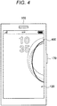
- the loop object 400 described above gradually increases in size as illustrated in Fig. 4 as time passes from the start of the authentication process. Then, when the authentication process is successful, the control unit 160 causes the display unit 120 to display a home screen. Note that, in a case where the authentication process fails, the control unit 160 may distort the loop object 400 as a whole. Moreover, in a case where a user tries the authentication process again, and the authentication process fails again, the loop object 400 whose shape is distorted by the first authentication process may be further deformed. In the deformation, the degree of distortion may be increased such that the state after the first failure and the state after the second failure can be distinguished, or the shape of the loop object 400 may be changed while being distorted as a whole.
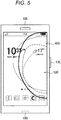
- Fig. 5 is an explanatory view illustrating a home screen.
- the home screen is an application selection screen that includes icons of one or more applications.
- the loop object 400 is constantly included.
- the control unit 160 may change a shape, color, or size of the loop object 400 every moment. With this configuration, a user can feel that the terminal device 100 is operating as if the terminal device 100 is a living body.
- Fig. 5 illustrates an example in which the loop object 400 is superimposed on the icon.
- the loop object 400 is a background object, basically, in the area where the icon is disposed, the loop object 400 is hidden behind the icon and cannot be seen, but in a case where the icon has transparency, as illustrated in Fig. 5 , the loop object 400 may be superimposed on the icon.
- the subsequent drawings are similar to Fig. 5 .
- a home screen may include a plurality of pages. Each page contains a different icon. In a case where the home screen includes a plurality of pages, any one of the pages is displayed on the display unit 120 as the home screen.
- the control unit 160 can switch a page displayed as the home screen on the display unit 120 on the basis of, for example, a swipe operation by a user.
- Fig. 6 is an explanatory view illustrating a home screen in which a page is switched by a swipe operation.
- the control unit 160 changes the appearance of the loop object 400 along with switching of the page.
- the control unit 160 may move the loop object 400 by the amount smaller than the page swipe amount in the same direction as a page swipe direction. According to such a configuration, a user can feel swipe like a viewpoint movement in a virtual space in which an icon and the loop object 400 are disposed.
- a movement amount of the loop object 400 smaller than a swipe amount of the page, it is possible to express a sense of depth and a three-dimensional effect of the loop object 400.
- a home screen may pop up information for assisting a user's operation, information for informing a user, or the like.
- the terminal device 100 of the present disclosure disposes the loop object 400 at a position corresponding to the pop-up display.
- Fig. 7 is an explanatory view illustrating the home screen including the pop-up display.
- the control unit 160 disposes the loop object 400 close to the upper end of the display unit 120. With such a configuration, it is expected that the user's attention is directed to the pop-up display 410 since the pop-up display 410 is closed up.
- control unit 160 may not cause the loop object 400 to react to all pop-up displays, and may cause the loop object 400 to react only to specific pop-up displays.
- the control unit 160 changes the loop object 400 in accordance with a power state of the terminal device 100.
- a power state of the terminal device 100 For example, with reference to Fig. 8 , a specific example of display control in a case where a remaining battery capacity of the terminal device 100 is less than a threshold will be described.
- Fig. 8 is an explanatory view illustrating a home screen displayed in a case where a remaining battery capacity of the terminal device 100 is less than a threshold.
- the control unit 160 moves the loop object 400 to the lower end side of the display unit 120.
- a threshold for example, 15%
- connection terminal 190 for charging is provided on a lower end side of the display unit 120, it can be said that the loop object 400 is disposed close to a connection terminal related to a state where the battery residual amount of the terminal device 100 is low. With such a configuration, an effect of indirectly prompting a user to charge a battery via the connection terminal 190 is also expected.
- the loop object 400 has red color (a solid line expresses red color). Generally, red makes it easy for a user to recall a warning. By making the loop object 400 red in a case where the remaining battery capacity is low, it is possible to make a user strongly recognize the situation where the remaining battery capacity is low.
- control unit 160 moves the loop object 400 to the arrangement illustrated in Fig. 9 .
- Fig. 9 is an explanatory view illustrating a home screen displayed in a case where the terminal device 100 is in a charging state.
- the control unit 160 disposes the loop object 400 such that each curved object forming the loop object 400 forms a circular arc of a concentric circle centered on the vicinity of the connection terminal 190.
- the loop object 400 since it looks as if ripples are spreading from the connection terminal 190, it is possible for a user to indirectly grasp the charging state in which power is coming from the connection terminal 190.
- the control unit 160 lengthens a radial distance of each of the curved objects forming the loop object 400 and moves the loop object 400 to an upper side of the display unit 120. Furthermore, the control unit 160 causes the loop object 400 to increase colors other than red as charging proceeds and the battery charge increases. With this configuration, a user can grasp the remaining battery capacity from the position and color of the loop object 400 even in a charging state.
- control unit 160 moves the loop object 400 to a neutral position.
- Fig. 11 is an explanatory view illustrating the loop object 400 moved to a neutral position.
- the neutral position of the loop object 400 may be a position that surrounds the center of the display unit 120. According to such a configuration, it is possible to provide a user with a feeling as if the force acting on the loop object 400 by the connection of the power supply cable has been released.
- control unit 160 disposes the loop object 400 so as to surround the icon corresponding to the application.
- Fig. 12 is an explanatory view illustrating an arrangement example of an icon of the loop object 400.
- the control unit 160 disposes the loop object 400 so as to surround the icon 420. With such a configuration, it is expected that the user's attention is directed to the icon 420.
- the application to be focused on may be an application that satisfies predetermined conditions.
- the predetermined conditions include an application whose icon is displayed on the home screen for the first time after installation, an application whose icon is displayed on the home screen for the first time after being updated, an application in which a specific event occurs in the application, and the like.
- a position of the loop object 400 changes with a state change of the terminal device 100.
- the position change of the loop object 400 is not performed at an instantaneous switching, but is performed with an animation.
- the change from the position of the loop object 400 on the home screen illustrated in Fig. 5 to the position of the loop object 400 on the charging screen illustrated in Fig. 9 is realized by continuous movement.
- the position of the loop object 400 may change on the basis of an element other than the state of the terminal device 100.
- the control unit 160 may move the loop object 400 to the tapped position, or the spread of ripples due to tapping may be expressed by fluctuation of the loop object 400.
- the configuration of the terminal device 100 according to the embodiment of the present disclosure has been described above. Next, with reference to Fig. 13 , an operation of the terminal device 100 by the embodiment of the present disclosure will be arranged.
- Fig. 13 is a flowchart indicating an operation of the terminal device 100 according to the embodiment of the present disclosure.
- the control unit 160 disposes the loop object 400 at a position corresponding to the fingerprint reader 170 (S208). Thereafter, the control unit 160 gradually enlarges the loop object 400 (S212) while the authentication process is not successful (S216/No) and has not yet timed out (S220/No). In a case where the fingerprint authentication has timed out (S220/Yes), the operation ends.
- control unit 160 causes the display unit 120 to display a home screen including the loop object 400 (S224).
- control unit 160 moves the loop object 400 according to a state change of the terminal device 100 (S228, S232). Then, the processes of S228 and S232 are repeated until the terminal device 100 transitions to a sleep mode (S236/No), and the operation ends with the transition of the terminal device 100 to a sleep mode (S236/Yes).
- the position, shape, size, color, or the like of the background object changes according to a state change of the terminal device 100.
- a user can indirectly recognize a state of the terminal device 100 by viewing the background object.
- the background object 400 has been described above as an example of the background object, the background object is not limited to the loop object 400.
- the background object may be a band-like object having a twist, a single curved object, or an object having a square shape such as a quadrangle or a triangle.
- the loop object 400 may be displayed on another screen.
- the loop object 400 may also be displayed on the lock screen. According to such a configuration, a user can indirectly grasp a state of the terminal device 100 without canceling the lock state by viewing the loop object 400 on the lock screen.
- each step in the process of the terminal device 100 in the present specification does not necessarily have to be processed chronologically in the order described as the flowchart.
- each step in the process of the terminal device 100 may be processed in an order different from the order described as the flowchart or may be processed in parallel.
Landscapes
- Engineering & Computer Science (AREA)
- Theoretical Computer Science (AREA)
- General Engineering & Computer Science (AREA)
- Physics & Mathematics (AREA)
- General Physics & Mathematics (AREA)
- Human Computer Interaction (AREA)
- Computer Hardware Design (AREA)
- User Interface Of Digital Computer (AREA)
- Telephone Function (AREA)
Abstract
Description
- The present disclosure relates to an information processing apparatus, method, and program.
- In recent years, information processing apparatuses such as mobile phones and smartphones are widely used. A display screen of an information processing apparatus generally includes display that directly indicates a state of the information processing apparatus, such as a battery-shaped indicator indicating a remaining battery capacity and an antenna-shaped indicator indicating a radio wave reception environment. Display control in an information processing apparatus is disclosed, for example, in Patent Document 1.
- Patent Document 1: Japanese Patent Application Laid-Open No.
2011-141825 - In addition to or instead of display directly indicating a state of an information processing apparatus described above, it is desired that a display indirectly indicating a state of an information processing apparatus is performed.
- Therefore, the present disclosure proposes a new and improved information processing apparatus, method, and program, capable of indirectly expressing a state change of an information processing apparatus.
- According to the present disclosure, there is provided an information processing apparatus which includes a display control unit that generates a display screen including a background object, and the display control unit moves the background object in accordance with a state change of the information processing apparatus.
- Furthermore, according to the present disclosure, there is provided a method which is performed by an information processing apparatus, the method including generating a display screen including a background object by a processor and moving the background object according to a state change of the information processing apparatus.
- Furthermore, according to the present disclosure, there is provided a program for causing a computer to function as an information processing apparatus including a display control unit for generating a display screen including a background object, the display control unit moving the background object in accordance with a state change of the information processing apparatus.
- As described above, according to the present disclosure, it is possible to indirectly express a state change of an information processing apparatus.
- Note that, the above-described effect is not necessarily limited, and together with or in place of the above-described effect, any one of the effects described in the present specification or other effects that can be grasped from the present specification may be exerted.
-
-
Fig. 1 is a view illustrating an appearance of a terminal device of the present disclosure. -
Fig. 2 is an explanatory view illustrating a functional configuration of the terminal device. -
Fig. 3 is an explanatory view illustrating an authentication processing screen displayed during fingerprint authentication. -
Fig. 4 is an explanatory view illustrating an authentication processing screen displayed during fingerprint authentication. -
Fig. 5 is an explanatory view illustrating a home screen. -
Fig. 6 is an explanatory view illustrating a home screen in which a page is switched by a swipe operation. -
Fig. 7 is an explanatory view showing a home screen including a pop-up display. -
Fig. 8 is an explanatory view illustrating a home screen displayed in a case where a remaining battery capacity of the terminal device is less than a threshold. -
Fig. 9 is an explanatory view illustrating a home screen displayed in a case where a state of a terminal device is in a charging state. -
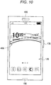
Fig. 10 is an explanatory view illustrating a home screen displayed in a case where a state of a terminal device is in a charging state. -
Fig. 11 is an explanatory view illustrating a loop object moved to a neutral position. -
Fig. 12 is an explanatory view illustrating an arrangement example of an icon of a loop object. -
Fig. 13 is a flowchart indicating an operation of the terminal device according to an embodiment of the present disclosure. - A preferred embodiment of the present disclosure will be described in detail below with reference to the accompanying drawings. Note that, in the present specification and the drawings, the same reference numerals are given to components having substantially the same functional configuration, and redundant explanation will be omitted.
- Furthermore, the present disclosure will be described in order below.
- 1. Appearance Configuration of Terminal Device
- 2. Function of Terminal Device
- 3. Specific Example of Display Control
- 4. Operation of Terminal Device
- 5. Conclusion
-
Fig. 1 is a view illustrating an appearance of aterminal device 100 of the present disclosure. As illustrated inFig. 1 , for example, theterminal device 100 may be a smartphone. In theterminal device 100, adisplay unit 120 and atouch panel 130 are disposed on a front surface of a housing. - Furthermore, in the
terminal device 100, afingerprint reader 170 and apower button 141 are disposed on aside surface 100S of the housing. Thepower button 141 is disposed below thefingerprint reader 170. When thefingerprint reader 170 is pressed, thepower button 141 disposed below thefingerprint reader 170 is pressed, and the power of theterminal device 100 is turned on. Alternatively, the state of theterminal device 100 is switched from a sleep state to a state in which a lock screen is displayed on thedisplay unit 120 by pressing thepower button 141. Note that, on the lock screen, functions that a user can execute on theterminal device 100 are limited. - Furthermore, a user can perform a fingerprint image registration operation and a collation operation by bringing a finger into contact with the
fingerprint reader 170 disposed on thepower button 141. The operation of a finger for causing thefingerprint reader 170 to read a fingerprint can be divided into a touch operation and a push operation. - The touch operation is an operation in which a finger touches a detection surface of the
fingerprint reader 170. In the touch operation, a force with which a finger presses the detection surface is weaker than the push operation as described later. In the touch operation, thefingerprint reader 170 reads a fingerprint image (hereinafter also referred to as a "fingerprint image") in a state where thepower button 141 is not pressed. Registration of a fingerprint may be performed by the touch operation. Since it is easy for a user to operate the touch operation, the user can relatively easily perform the fingerprint registration process or the fingerprint authentication process a plurality of times. When a fingerprint is initially registered on theterminal device 100, there is a possibility that a user may register a fingerprint a plurality of times. Therefore, the user can perform fingerprint registration relatively easily by performing the fingerprint registration process by touch operation. Note that, in the fingerprint registration process, the features of a fingerprint image read by the touch operation are registered. - The push operation is an operation to press a detection surface of the
fingerprint reader 170 in reading a fingerprint. In the push operation, the force with which a finger presses the detection surface is stronger than the force in the touch operation. In the push operation, thefingerprint reader 170 reads a fingerprint image in a state where thepower button 141 is pressed by thefingerprint reader 170. In a case where theterminal device 100 is in a sleep state when fingerprint authentication is performed, the user cancels a sleep state and puts theterminal device 100 in a state where a fingerprint authentication process can be activated. In order to cancel this sleep state, the user presses thepower button 141. For example, the user presses thepower button 141 via thefingerprint reader 170 to start fingerprint authentication. As a result, theterminal device 100 is ready to start fingerprint authentication. Then, the authentication is performed by collating the feature of the fingerprint image read by the push operation with the feature of the registered fingerprint image. - As described above, in the
terminal device 100 according to the present embodiment, turn-on of the power or the cancellation of a sleep state and the start of fingerprint authentication may be simultaneously performed by the push operation. Therefore, the user can perform, for example, the cancellation of a sleep state and the fingerprint authentication by one operation. Note that, the lock or sleep state of theterminal device 100 may be canceled by operating an operation key other than thepower button 141. Furthermore, thepower button 141 may not be disposed, and thefingerprint reader 170 may directly press the power switch. - Furthermore, on the bottom surface of the
terminal device 100, aconnection terminal 190 to which a cable is connected is disposed. A data communication cable for communicating data with an external device, or a power supply cable for supplying power may be connected to theconnection terminal 190. Such aconnection terminal 190 may be, for example, a USB port. - Note that, in
Fig. 1 , although a smart phone has been illustrated as an example of theterminal device 100, theterminal device 100 is not limited to a smart phone. For example, theterminal device 100 may be an information processing apparatus such as a personal computer (PC), a home video processor (DVD recorder, video deck, etc.), a personal digital assistants (PDA), a home gaming device, a home appliance, a mobile phone, a portable music playback device, a portable video processor, and a portable game apparatus. - The appearance configuration of the
terminal device 100 of the present disclosure has been described above. With reference toFig. 2 , functions of theterminal device 100 of the present disclosure will be described next. -
Fig. 2 is an explanatory view illustrating a functional configuration of theterminal device 100. As illustrated inFig. 2 , theterminal device 100 includes acontrol unit 160, a wirelesscommunication processing unit 110, adisplay unit 120, atouch panel 130, anoperation key 140, amemory 150, and aGPS unit 180. Theterminal device 100 further includes avoice processing unit 103, aspeaker 104, amicrophone 105, a short distance wirelesscommunication processing unit 107, amotion sensor 108, acamera 109, andantennas - The
control unit 160 transmits a control command to the wirelesscommunication processing unit 110 via a control line CL. Furthermore, thecontrol unit 160 also reads a program (software) stored in thememory 150 via the control line CL. Then, thecontrol unit 160 controls each part of theterminal device 100 by executing the read program. Thecontrol unit 160 also executes a fingerprint authentication program stored in thememory 150 to perform fingerprint registration processing and authentication processing. Thecontrol unit 160 may have functions of a feature extraction unit that extracts features of a fingerprint and a collating unit that performs collating of the fingerprint. Thecontrol unit 160 includes, for example, a central processing unit (CPU). Note that, thecontrol unit 160 may have a function of a detection unit that detects that authentication processing has been started. Furthermore, thecontrol unit 160 may have a function of a display control unit for displaying a lock screen, an authentication processing screen, and a home screen as described later. Display elements generated by the display control unit include a UI used for operation, a character string, an image (moving image, still image), a window, an icon, a background object, and the like. - The wireless
communication processing unit 110 performs processing of transmission and reception of a wireless signal under the control of thecontrol unit 160. Furthermore, theterminal device 100 further includes theantenna 101 for performing wireless communication with a base station, and theantenna 101 is connected to the wirelesscommunication processing unit 110. - In addition, in a case where the
terminal device 100 performs data communication or mail transmission/reception via a network such as the Internet, the wirelesscommunication processing unit 110 may perform transmission/reception processing under the control of thecontrol unit 160. For example, the data received by the wirelesscommunication processing unit 110 is stored in thememory 150, and the control of thecontrol unit 160 performs processing such as display based on the stored data. Furthermore, the data stored in thememory 150 is supplied to the wirelesscommunication processing unit 110 and transmitted wirelessly. - The
memory 150 stores data prepared in advance, such as a program, and stores data generated by a user operation. Storage of data in thememory 150 and reading of data from thememory 150 are performed under the control of thecontrol unit 160. - The
voice processing unit 103 demodulates supplied voice data to obtain an analog voice signal. The voice data supplied to thevoice processing unit 103 may be voice data for a call received by the wirelesscommunication processing unit 110. At this time, the wirelesscommunication processing unit 110 supplies voice data to thevoice processing unit 103 via a data line DL. The analog voice signal obtained by thevoice processing unit 103 is supplied to thespeaker 104, and voice is output from thespeaker 104. - Furthermore, the
voice processing unit 103 converts a voice signal output from themicrophone 105 into voice data of a transmission format. Then, the voice data converted by thevoice processing unit 103 is supplied to the wirelesscommunication processing unit 110 via the data line DL. Furthermore, the voice data supplied to the wirelesscommunication processing unit 110 is packetized and wirelessly transmitted. - Note that, in a case where the
terminal device 100 does not have a voice call function, thevoice processing unit 103, thespeaker 104, and themicrophone 105 may be omitted. - The
display unit 120 displays various display screens such as a lock screen, an authentication processing screen, and a home screen on the display panel under the control of thecontrol unit 160. As the display panel, for example, a liquid crystal display panel or an organic electro-luminescence (EL) display panel is used. - The
touch panel 130 detects a touched position when the surface (detection surface) of the display panel is touched with an object such as a finger or a pen. For example, thetouch panel 130 detects that a finger or a pen has contacted with an area or the like in which the display panel displays an image or the like. Note that, thetouch panel 130 may be stacked on the display panel or may be integrated with the display panel. Thetouch panel 130 may be, for example, a capacitance type. In this case, thetouch panel 130 detects that the surface of the display panel is touched with a finger or the like from a change in capacitance. - Data on the touch position detected by the
touch panel 130 is transmitted to thecontrol unit 160. Thecontrol unit 160 executes an application being activated on the basis of the supplied touch position. The touch position is indicated by coordinate positions of, for example, an X axis (horizontal axis) and a Y axis (vertical axis) which are two orthogonal axes. The coordinate position detected by thetouch panel 130 is not limited to one point. In a case where a plurality of points is simultaneously touched, thecontrol unit 160 performs control based on a plurality of the points detected. Furthermore, when a wide range of thetouch panel 130 is touched simultaneously, thecontrol unit 160 detects the entire touched range. - Furthermore, the
terminal device 100 further includes theoperation key 140 such as a power switch 142. Operation information of theoperation key 140 is transmitted to thecontrol unit 160. As described above, the surface of theoperation key 140 may be provided with afingerprint reader 170 that reads the surface (fingerprint) of a placed finger. Thefingerprint reader 170 may read a fingerprint of a finger having touched the detection surface disposed on its surface and may send the read image to thecontrol unit 160. Further, thefingerprint reader 170 stores the read image in thememory 150. Thefingerprint reader 170 includes a plurality of sensor elements disposed in a two-dimensional array. For thefingerprint reader 170, for example, an optical method, an electric field strength measurement method, a capacitance method, or the like is used. - The
GPS unit 180 acquires the position of theterminal device 100 by performing triangulation on the basis of information included in radio waves received from satellites. TheGPS unit 180 is connected to anantenna 181 for receiving radio waves from satellites. - The short distance wireless
communication processing unit 107 is used to perform short distance wireless communication with another terminal. The short distance wireless communication method may be, for example, Wi-Fi, Bluetooth (registered trademark), or Zigbee (registered trademark). The short distance wirelesscommunication processing unit 107 is connected to theantenna 106 for transmitting radio waves to another terminal or receiving radio waves from another terminal. - The
motion sensor 108 is used to detect the movement or attitude of theterminal device 100. Themotion sensor 108 may detect the acceleration of theterminal device 100 by, for example, an acceleration sensor. Themotion sensor 108 may also detect angular acceleration or angular velocity of theterminal device 100 by a gyro sensor. Furthermore, thecamera 109 is also used to capture an image. - Note that, the
terminal device 100 includes a power supply unit (battery) not illustrated. Each block in theterminal device 100 is driven by the power supplied from the power supply unit. - The functions of the
terminal device 100 of the present disclosure have been described above. Among the above-described functions, the embodiment of the present disclosure particularly relates to a display screen generation function by thecontrol unit 160. Then, the display screen generation function by thecontrol unit 160 will be more specifically described below. - The
terminal device 100 of the present disclosure displays a display screen including a background object having motion. Theterminal device 100 changes a position, shape, size, color or the like of the background object according to a state change of theterminal device 100. For example, theterminal device 100 moves the background object to a position corresponding to the configuration related to a state of theterminal device 100. With this configuration, a user can indirectly recognize a state of theterminal device 100 by viewing the background object. Hereinafter, several specific examples of the display screen including such a background object will be sequentially described. -
Fig. 3 is an explanatory view illustrating an authentication processing screen displayed during fingerprint authentication. When the user's finger contacts a detection surface of thefingerprint reader 170, fingerprint authentication is started, and thecontrol unit 160 causes thedisplay unit 120 to display an authentication processing screen illustrated inFig. 3 . - As illustrated in
Fig. 3 , the authentication processing screen includes aloop object 400 which is an example of a background object. Theloop object 400 includes two or more curved objects overlapping each other. Each of the two or more curved objects has a ring shape (loop shape), and approximately half of each curved object is illustrated inFig. 3 . - The
control unit 160 disposes theloop object 400 at a position corresponding to the configuration related to a state of theterminal device 100. Since thefingerprint reader 170 relates to the state in which the authentication process is being performed, while the authentication processing is being performed, thecontrol unit 160 disposes theloop object 400 close to the position of thefingerprint reader 170 as illustrated inFig. 3 . The user can indirectly grasp that the authentication process is being performed because theloop object 400 is disposed close to thefingerprint reader 170. - Note that each curved object forming the
loop object 400 may have a different color. Furthermore, the same curved object may have different colors depending on the position. InFig. 3 and the subsequent drawings, the color possessed by each curved object is expressed by a line type such as a solid line or a broken line. - The
loop object 400 described above gradually increases in size as illustrated inFig. 4 as time passes from the start of the authentication process. Then, when the authentication process is successful, thecontrol unit 160 causes thedisplay unit 120 to display a home screen. Note that, in a case where the authentication process fails, thecontrol unit 160 may distort theloop object 400 as a whole. Moreover, in a case where a user tries the authentication process again, and the authentication process fails again, theloop object 400 whose shape is distorted by the first authentication process may be further deformed. In the deformation, the degree of distortion may be increased such that the state after the first failure and the state after the second failure can be distinguished, or the shape of theloop object 400 may be changed while being distorted as a whole. -
Fig. 5 is an explanatory view illustrating a home screen. As illustrated inFig. 5 , the home screen is an application selection screen that includes icons of one or more applications. On the home screen also, as illustrated inFig. 5 , theloop object 400 is constantly included. Thecontrol unit 160 may change a shape, color, or size of theloop object 400 every moment. With this configuration, a user can feel that theterminal device 100 is operating as if theterminal device 100 is a living body. Note thatFig. 5 illustrates an example in which theloop object 400 is superimposed on the icon. Since theloop object 400 is a background object, basically, in the area where the icon is disposed, theloop object 400 is hidden behind the icon and cannot be seen, but in a case where the icon has transparency, as illustrated inFig. 5 , theloop object 400 may be superimposed on the icon. The subsequent drawings are similar toFig. 5 . - A home screen may include a plurality of pages. Each page contains a different icon. In a case where the home screen includes a plurality of pages, any one of the pages is displayed on the
display unit 120 as the home screen. Thecontrol unit 160 can switch a page displayed as the home screen on thedisplay unit 120 on the basis of, for example, a swipe operation by a user. -
Fig. 6 is an explanatory view illustrating a home screen in which a page is switched by a swipe operation. As illustrated inFig. 6 , when the page on the home screen is switched, the displayed icon changes. Furthermore, as illustrated inFig. 6 , thecontrol unit 160 changes the appearance of theloop object 400 along with switching of the page. For example, thecontrol unit 160 may move theloop object 400 by the amount smaller than the page swipe amount in the same direction as a page swipe direction. According to such a configuration, a user can feel swipe like a viewpoint movement in a virtual space in which an icon and theloop object 400 are disposed. Furthermore, by making a movement amount of theloop object 400 smaller than a swipe amount of the page, it is possible to express a sense of depth and a three-dimensional effect of theloop object 400. - A home screen may pop up information for assisting a user's operation, information for informing a user, or the like. In a state where such a pop-up display is included in the home screen, it is desirable for a user to pay attention to the pop-up display. Therefore, in the state where the pop-up display is included in the home screen, the
terminal device 100 of the present disclosure disposes theloop object 400 at a position corresponding to the pop-up display. -
Fig. 7 is an explanatory view illustrating the home screen including the pop-up display. As illustrated inFig. 7 , in a case where the pop-updisplay 410 is positioned at an upper end of thedisplay unit 120, thecontrol unit 160 disposes theloop object 400 close to the upper end of thedisplay unit 120. With such a configuration, it is expected that the user's attention is directed to the pop-updisplay 410 since the pop-updisplay 410 is closed up. - Note that, the
control unit 160 may not cause theloop object 400 to react to all pop-up displays, and may cause theloop object 400 to react only to specific pop-up displays. - The
control unit 160 changes theloop object 400 in accordance with a power state of theterminal device 100. Hereinafter, with reference toFig. 8 , a specific example of display control in a case where a remaining battery capacity of theterminal device 100 is less than a threshold will be described. -
Fig. 8 is an explanatory view illustrating a home screen displayed in a case where a remaining battery capacity of theterminal device 100 is less than a threshold. As illustrated inFig. 8 , in a case where the remaining battery capacity of theterminal device 100 is less than a threshold (for example, 15%), thecontrol unit 160 moves theloop object 400 to the lower end side of thedisplay unit 120. By disposing theloop object 400 on the lower end side of thedisplay unit 120, a user can indirectly grasp that the remaining battery capacity is low. - Furthermore, since the
connection terminal 190 for charging is provided on a lower end side of thedisplay unit 120, it can be said that theloop object 400 is disposed close to a connection terminal related to a state where the battery residual amount of theterminal device 100 is low. With such a configuration, an effect of indirectly prompting a user to charge a battery via theconnection terminal 190 is also expected. - Further, in
Fig. 8 , theloop object 400 has red color (a solid line expresses red color). Generally, red makes it easy for a user to recall a warning. By making theloop object 400 red in a case where the remaining battery capacity is low, it is possible to make a user strongly recognize the situation where the remaining battery capacity is low. - When the state of the
terminal device 100 is in a charging state in which a power supply cable is inserted into theconnection terminal 190, thecontrol unit 160 moves theloop object 400 to the arrangement illustrated inFig. 9 . -
Fig. 9 is an explanatory view illustrating a home screen displayed in a case where theterminal device 100 is in a charging state. As illustrated inFig. 9 , in the charging state, thecontrol unit 160 disposes theloop object 400 such that each curved object forming theloop object 400 forms a circular arc of a concentric circle centered on the vicinity of theconnection terminal 190. According to the arrangement of theloop object 400, since it looks as if ripples are spreading from theconnection terminal 190, it is possible for a user to indirectly grasp the charging state in which power is coming from theconnection terminal 190. - Furthermore, as charging proceeds and the battery charge increases, as illustrated in
Fig. 10 , thecontrol unit 160 lengthens a radial distance of each of the curved objects forming theloop object 400 and moves theloop object 400 to an upper side of thedisplay unit 120. Furthermore, thecontrol unit 160 causes theloop object 400 to increase colors other than red as charging proceeds and the battery charge increases. With this configuration, a user can grasp the remaining battery capacity from the position and color of theloop object 400 even in a charging state. - Note that, when the power supply cable is disconnected from the
connection terminal 190, thecontrol unit 160 moves theloop object 400 to a neutral position. -
Fig. 11 is an explanatory view illustrating theloop object 400 moved to a neutral position. As illustrated inFig. 11 , the neutral position of theloop object 400 may be a position that surrounds the center of thedisplay unit 120. According to such a configuration, it is possible to provide a user with a feeling as if the force acting on theloop object 400 by the connection of the power supply cable has been released. - In a case where there is an application to be focused on in the
terminal device 100, thecontrol unit 160 disposes theloop object 400 so as to surround the icon corresponding to the application. -
Fig. 12 is an explanatory view illustrating an arrangement example of an icon of theloop object 400. In a case where anicon 420 illustrated inFig. 12 is the icon of the application to be focused on, thecontrol unit 160 disposes theloop object 400 so as to surround theicon 420. With such a configuration, it is expected that the user's attention is directed to theicon 420. - Note that, the application to be focused on may be an application that satisfies predetermined conditions. The predetermined conditions include an application whose icon is displayed on the home screen for the first time after installation, an application whose icon is displayed on the home screen for the first time after being updated, an application in which a specific event occurs in the application, and the like.
- As described above, a position of the
loop object 400 changes with a state change of theterminal device 100. The position change of theloop object 400 is not performed at an instantaneous switching, but is performed with an animation. For example, the change from the position of theloop object 400 on the home screen illustrated inFig. 5 to the position of theloop object 400 on the charging screen illustrated inFig. 9 is realized by continuous movement. - Furthermore, the position of the
loop object 400 may change on the basis of an element other than the state of theterminal device 100. For example, in a case where the user taps thedisplay unit 120, thecontrol unit 160 may move theloop object 400 to the tapped position, or the spread of ripples due to tapping may be expressed by fluctuation of theloop object 400. - The configuration of the
terminal device 100 according to the embodiment of the present disclosure has been described above. Next, with reference toFig. 13 , an operation of theterminal device 100 by the embodiment of the present disclosure will be arranged. -
Fig. 13 is a flowchart indicating an operation of theterminal device 100 according to the embodiment of the present disclosure. First, as illustrated inFig. 13 , when a user's finger contacts the fingerprint reader 170 (S204), fingerprint authentication is started, and thecontrol unit 160 disposes theloop object 400 at a position corresponding to the fingerprint reader 170 (S208). Thereafter, thecontrol unit 160 gradually enlarges the loop object 400 (S212) while the authentication process is not successful (S216/No) and has not yet timed out (S220/No). In a case where the fingerprint authentication has timed out (S220/Yes), the operation ends. - On the other hand, in a case where the fingerprint authentication is successful (S216/Yes), the
control unit 160 causes thedisplay unit 120 to display a home screen including the loop object 400 (S224). - Thereafter, the
control unit 160 moves theloop object 400 according to a state change of the terminal device 100 (S228, S232). Then, the processes of S228 and S232 are repeated until theterminal device 100 transitions to a sleep mode (S236/No), and the operation ends with the transition of theterminal device 100 to a sleep mode (S236/Yes). - As described above, according to the embodiment of the present disclosure, the position, shape, size, color, or the like of the background object (loop object) changes according to a state change of the
terminal device 100. With this configuration, a user can indirectly recognize a state of theterminal device 100 by viewing the background object. - Note that, although the preferred embodiments of the present disclosure have been described in detail with reference to the attached drawings, the technical scope of the present disclosure is not limited to such examples. It is obvious that persons having general knowledge in the technical field of the present disclosure can conceive various variations or modifications within the scope of the technical idea described in the claims, and these are naturally understood to belong to the technical scope of the present disclosure.
- For example, although the
loop object 400 has been described above as an example of the background object, the background object is not limited to theloop object 400. For example, the background object may be a band-like object having a twist, a single curved object, or an object having a square shape such as a quadrangle or a triangle. - Furthermore, although the example in which the
loop object 400 is mainly displayed on the home screen has been described above, theloop object 400 may be displayed on another screen. For example, theloop object 400 may also be displayed on the lock screen. According to such a configuration, a user can indirectly grasp a state of theterminal device 100 without canceling the lock state by viewing theloop object 400 on the lock screen. - Furthermore, each step in the process of the
terminal device 100 in the present specification does not necessarily have to be processed chronologically in the order described as the flowchart. For example, each step in the process of theterminal device 100 may be processed in an order different from the order described as the flowchart or may be processed in parallel. - Furthermore, it is possible to create a computer program for causing hardware such as a CPU, a ROM, and a RAM incorporated in the
terminal device 100 to exhibit the same function as each configuration of theterminal device 100 described above. Furthermore, a storage medium storing the computer program is provided. - Furthermore, the effects described in the present specification are merely illustrative or exemplary and by no means limiting. That is, the technique according to the present disclosure can exhibit other effects obvious to those skilled in the art from the description of the present specification together with or instead of the above-described effects.
- Furthermore, the following configurations also belong to the technical scope of the present disclosure.
- (1) An information processing apparatus, including
a display control unit that generates a display screen including a background object,
in which the display control unit moves a background object in accordance with a state change of the information processing apparatus. - (2) The information processing apparatus according to (1), in which the background object includes one or more curved objects.
- (3) The information processing apparatus according to (1) or (2), in which the display control unit disposes the background object at a position corresponding to a configuration related to a state of the information processing apparatus among configurations of the information processing apparatus.
- (4) The information processing apparatus according to (3), further including
a fingerprint reader for fingerprint authentication,
in which the display control unit disposes the background object at a position corresponding to the fingerprint reader in a case where the fingerprint authentication is performed in the information processing apparatus and after the fingerprint authentication is performed. - (5) The information processing apparatus according to (3) or (4), further including
a connection terminal to which a cable is connected,
in which the display control unit disposes the background object at a position corresponding to the connection terminal in a case where the cable is connected to the connection terminal. - (6) The information processing apparatus according to (5), in which the display control unit moves the background object to a neutral position in a case where the cable is disconnected from the connection terminal.
- (7) The information processing apparatus according to (5) or (6),
in which the cable connected to the connection terminal includes a power supply cable, and
the display control unit brings the background object close to the connection terminal in accordance with a decrease in a remaining battery capacity of the information processing apparatus. - (8) The information processing apparatus according to (1) to (7), in which, in a case where the display screen includes a pop-up display, the display control unit disposes the background object at a position corresponding to the pop-up display.
- (9) The information processing apparatus according to any one of (1) to (8),
in which the display screen is an application selection screen including one or more application icons, and
the display control unit changes an icon included in the selection screen in response to a swipe operation and changes an appearance of the background object in response to the swipe operation. - (10) The information processing apparatus according to (9), in which the display control unit disposes the background object so as to surround an icon of an application that satisfies a predetermined condition.
- (11) The information processing apparatus according to any one of (1) to (10), in which the display control unit further changes at least one of a shape, a size, or a color of the background object in accordance with a state change of the information processing apparatus.
- (12) The information processing apparatus according to (11), in which the display control unit makes the background object close to a red color in accordance with a decrease in a remaining battery capacity of the information processing apparatus.
- (13) A method to be performed by an information processing apparatus, including:
- generating a display screen including a background object by a processor; and
- moving the background object in accordance with a state change of the information processing apparatus.
- (14) A program for causing a computer to function as an information processing apparatus including
a display control unit that generates a display screen including a background object,
the display control unit moving the background object in accordance with a state change of the information processing apparatus. -
- 100 Terminal device
- 101 Antenna
- 103 Voice processing unit
- 104 Speaker
- 105 Microphone
- 106 Antenna
- 107 Short distance wireless communication processing unit
- 108 Motion sensor
- 109 Camera
- 110 Wireless communication processing unit
- 120 Display unit
- 130 Touch panel
- 140 Operation key
- 141 Power button
- 142 Power switch
- 150 Memory
- 160 Control unit
- 170 Fingerprint reader
- 171 Detection surface
- 180 GPS unit
- 181 Antenna
- 190 Connecting terminal
Claims (14)
- An information processing apparatus, comprising
a display control unit configured to generate a display screen including a background object,
wherein the display control unit moves the background object in accordance with a state change of the information processing apparatus. - The information processing apparatus according to claim 1, wherein the background object includes one or more curved objects.
- The information processing apparatus according to claim 1, wherein the display control unit disposes the background object at a position corresponding to a configuration related to a state of the information processing apparatus among configurations of the information processing apparatus.
- The information processing apparatus according to claim 3, further comprising
a fingerprint reader for fingerprint authentication,
wherein the display control unit disposes the background object at a position corresponding to the fingerprint reader in a case where the fingerprint authentication is performed in the information processing apparatus and after the fingerprint authentication is performed. - The information processing apparatus according to claim 3, further comprising
a connection terminal to which a cable is connected,
wherein the display control unit disposes the background object at a position corresponding to the connection terminal in a case where the cable is connected to the connection terminal. - The information processing apparatus according to claim 5, wherein the display control unit moves the background object to a neutral position in a case where the cable is disconnected from the connection terminal.
- The information processing apparatus according to claim 5,
wherein the cable connected to the connection terminal includes a power supply cable, and
the display control unit brings the background object close to the connection terminal in accordance with a decrease in a remaining battery capacity of the information processing apparatus. - The information processing apparatus according to claim 1, wherein in a case where the display screen includes a pop-up display, the display control unit disposes the background object at a position corresponding to the pop-up display.
- The information processing apparatus according to claim 1,
wherein the display screen is an application selection screen including one or more application icons, and
the display control unit changes an icon included in the selection screen in response to a swipe operation and changes an appearance of the background object in response to the swipe operation. - The information processing apparatus according to claim 9, wherein the display control unit disposes the background object so as to surround an icon of an application that satisfies a predetermined condition.
- The information processing apparatus according to claim 1, wherein the display control unit further changes at least one of a shape, a size, or a color of the background object in accordance with a state change of the information processing apparatus.
- The information processing apparatus according to claim 11, wherein the display control unit makes the background object close to a red color in accordance with a decrease in a remaining battery capacity of the information processing apparatus.
- A method to be performed by an information processing apparatus, comprising:generating a display screen including a background object by a processor; andmoving the background object in accordance with a state change of the information processing apparatus.
- A program for causing a computer to function as an information processing apparatus including
a display control unit configured to generate a display screen including a background object,
the display control unit moving the background object in accordance with a state change of the information processing apparatus.
Applications Claiming Priority (2)
| Application Number | Priority Date | Filing Date | Title |
|---|---|---|---|
| US201762462056P | 2017-02-22 | 2017-02-22 | |
| PCT/JP2017/045485 WO2018154940A1 (en) | 2017-02-22 | 2017-12-19 | Information processing device, method, and program |
Publications (3)
| Publication Number | Publication Date |
|---|---|
| EP3588254A1 true EP3588254A1 (en) | 2020-01-01 |
| EP3588254A4 EP3588254A4 (en) | 2020-01-15 |
| EP3588254B1 EP3588254B1 (en) | 2021-12-08 |
Family
ID=63252553
Family Applications (1)
| Application Number | Title | Priority Date | Filing Date |
|---|---|---|---|
| EP17898053.8A Active EP3588254B1 (en) | 2017-02-22 | 2017-12-19 | Information processing device, method, and program |
Country Status (5)
| Country | Link |
|---|---|
| US (1) | US10866689B2 (en) |
| EP (1) | EP3588254B1 (en) |
| JP (1) | JP6828134B2 (en) |
| CN (1) | CN110337631B (en) |
| WO (1) | WO2018154940A1 (en) |
Families Citing this family (1)
| Publication number | Priority date | Publication date | Assignee | Title |
|---|---|---|---|---|
| CN108594984A (en) * | 2018-04-24 | 2018-09-28 | 联想(北京)有限公司 | A kind of electronic equipment and control method |
Family Cites Families (18)
| Publication number | Priority date | Publication date | Assignee | Title |
|---|---|---|---|---|
| JP3420007B2 (en) * | 1996-12-19 | 2003-06-23 | 三菱電機株式会社 | Abnormal status display device of control monitoring system |
| US7222019B2 (en) | 2004-01-14 | 2007-05-22 | Yamaha Hatsudoki Kabushiki Kaisha | Vehicle image display apparatus and vehicle having the same |
| JP2005225484A (en) | 2004-01-14 | 2005-08-25 | Yamaha Motor Co Ltd | VEHICLE IMAGE DISPLAY DEVICE AND VEHICLE HAVING THE SAME |
| JP4447342B2 (en) * | 2004-01-30 | 2010-04-07 | 京セラ株式会社 | Mobile terminal device and information display device status display method |
| US20110016394A1 (en) * | 2005-04-18 | 2011-01-20 | Nettune, Inc. | Systems and methods of selection, characterization and automated sequencing of media content |
| JP2009053506A (en) | 2007-08-28 | 2009-03-12 | Murata Mach Ltd | Display device |
| US8446398B2 (en) * | 2009-06-16 | 2013-05-21 | Intel Corporation | Power conservation for mobile device displays |
| JP5526789B2 (en) | 2010-01-08 | 2014-06-18 | ソニー株式会社 | Information processing apparatus and program |
| KR102164453B1 (en) * | 2012-04-07 | 2020-10-13 | 삼성전자주식회사 | Object control method performed in device including transparent display, the device, and computer readable recording medium thereof |
| KR101990035B1 (en) * | 2012-10-31 | 2019-06-18 | 엘지전자 주식회사 | Mobile terminal and control method for the mobile terminal |
| KR20150026565A (en) * | 2013-09-03 | 2015-03-11 | 엘지전자 주식회사 | Mobile terminal and control method thereof |
| JP2015230560A (en) | 2014-06-04 | 2015-12-21 | 大日本印刷株式会社 | Display terminal device, program, and display method |
| US9977566B2 (en) * | 2014-06-24 | 2018-05-22 | Google Llc | Computerized systems and methods for rendering an animation of an object in response to user input |
| US20170371515A1 (en) * | 2014-11-19 | 2017-12-28 | Honda Motor Co., Ltd. | System and method for providing absolute and zone coordinate mapping with graphic animations |
| KR102318227B1 (en) | 2015-01-16 | 2021-10-27 | 삼성전자주식회사 | Apparatus and method for displaying information |
| KR102393508B1 (en) * | 2015-06-22 | 2022-05-03 | 엘지전자 주식회사 | Smart watch and method for contolling the same |
| US10725604B2 (en) * | 2016-03-30 | 2020-07-28 | Lenovo (Singapore) Pte. Ltd. | Virtual notifications |
| EP3416050B1 (en) * | 2016-12-26 | 2022-01-26 | Shenzhen Goodix Technology Co., Ltd. | Method and device for guiding fingerprint recognition |
-
2017
- 2017-12-19 JP JP2019501078A patent/JP6828134B2/en active Active
- 2017-12-19 CN CN201780086548.4A patent/CN110337631B/en active Active
- 2017-12-19 WO PCT/JP2017/045485 patent/WO2018154940A1/en not_active Ceased
- 2017-12-19 EP EP17898053.8A patent/EP3588254B1/en active Active
- 2017-12-19 US US16/485,796 patent/US10866689B2/en active Active
Also Published As
| Publication number | Publication date |
|---|---|
| US10866689B2 (en) | 2020-12-15 |
| EP3588254A4 (en) | 2020-01-15 |
| JPWO2018154940A1 (en) | 2020-01-09 |
| EP3588254B1 (en) | 2021-12-08 |
| JP6828134B2 (en) | 2021-02-10 |
| CN110337631A (en) | 2019-10-15 |
| WO2018154940A1 (en) | 2018-08-30 |
| CN110337631B (en) | 2022-11-18 |
| US20200050343A1 (en) | 2020-02-13 |
Similar Documents
| Publication | Publication Date | Title |
|---|---|---|
| US9773158B2 (en) | Mobile device having face recognition function using additional component and method for controlling the mobile device | |
| EP2557764B1 (en) | Mobile terminal and method of controlling the same | |
| EP2720126B1 (en) | Method and apparatus for generating task recommendation icon in a mobile device | |
| EP2808781B1 (en) | Method, storage medium, and electronic device for mirroring screen data | |
| US8588739B2 (en) | Mobile terminal, lock state control program for mobile terminal, and a method for controlling lock state of mobile terminal | |
| US10460093B2 (en) | Terminal device, method, and program | |
| KR20140026177A (en) | Method for controlling scrolling and apparatus for the same | |
| KR20140073232A (en) | Mobil terminal and Operating Method for the Same | |
| US20230350566A1 (en) | Electronic apparatus and method for processing input from stylus pen in electronic apparatus | |
| US11227595B2 (en) | Electronic device with speech recognition function, control method of electronic device with speech recognition function, and recording medium | |
| US11410647B2 (en) | Electronic device with speech recognition function, control method of electronic device with speech recognition function, and recording medium | |
| KR102051585B1 (en) | An electronic device and method having a function of hand writing using multi-touch | |
| US20150017958A1 (en) | Portable terminal and method for controlling provision of data | |
| KR20130037330A (en) | Mobile terminal and operation control method thereof | |
| EP3588254B1 (en) | Information processing device, method, and program | |
| CN109600514B (en) | Unlocking control method and device, mobile terminal and storage medium | |
| KR20150044757A (en) | Electronic device and method for controlling operation according to floating input | |
| JP2011221669A (en) | Input system | |
| EP4332736B1 (en) | Electronic device and method for controlling input of electronic pen thereof | |
| KR102908880B1 (en) | Electronic device and electronic pen for input control ant method thereof | |
| EP4455842A1 (en) | Electronic device, and notification and connection method for electronic pen | |
| KR20150102418A (en) | Mobile terminal and controlling method thereof | |
| CN118742881A (en) | Electronic device and method for displaying touch input or hovering input based on change of display area of rollable display |
Legal Events
| Date | Code | Title | Description |
|---|---|---|---|
| STAA | Information on the status of an ep patent application or granted ep patent |
Free format text: STATUS: THE INTERNATIONAL PUBLICATION HAS BEEN MADE |
|
| PUAI | Public reference made under article 153(3) epc to a published international application that has entered the european phase |
Free format text: ORIGINAL CODE: 0009012 |
|
| STAA | Information on the status of an ep patent application or granted ep patent |
Free format text: STATUS: REQUEST FOR EXAMINATION WAS MADE |
|
| 17P | Request for examination filed |
Effective date: 20190815 |
|
| AK | Designated contracting states |
Kind code of ref document: A1 Designated state(s): AL AT BE BG CH CY CZ DE DK EE ES FI FR GB GR HR HU IE IS IT LI LT LU LV MC MK MT NL NO PL PT RO RS SE SI SK SM TR |
|
| AX | Request for extension of the european patent |
Extension state: BA ME |
|
| A4 | Supplementary search report drawn up and despatched |
Effective date: 20191213 |
|
| RIC1 | Information provided on ipc code assigned before grant |
Ipc: G06F 3/0481 20130101AFI20191209BHEP Ipc: G06F 1/16 20060101ALI20191209BHEP Ipc: G06F 1/3215 20190101ALI20191209BHEP Ipc: G06F 1/3234 20190101ALI20191209BHEP Ipc: G06F 11/32 20060101ALI20191209BHEP Ipc: G06F 21/32 20130101ALI20191209BHEP |
|
| DAV | Request for validation of the european patent (deleted) | ||
| DAX | Request for extension of the european patent (deleted) | ||
| STAA | Information on the status of an ep patent application or granted ep patent |
Free format text: STATUS: EXAMINATION IS IN PROGRESS |
|
| 17Q | First examination report despatched |
Effective date: 20201022 |
|
| GRAP | Despatch of communication of intention to grant a patent |
Free format text: ORIGINAL CODE: EPIDOSNIGR1 |
|
| STAA | Information on the status of an ep patent application or granted ep patent |
Free format text: STATUS: GRANT OF PATENT IS INTENDED |
|
| INTG | Intention to grant announced |
Effective date: 20210705 |
|
| RAP1 | Party data changed (applicant data changed or rights of an application transferred) |
Owner name: SONY GROUP CORPORATION |
|
| GRAS | Grant fee paid |
Free format text: ORIGINAL CODE: EPIDOSNIGR3 |
|
| GRAA | (expected) grant |
Free format text: ORIGINAL CODE: 0009210 |
|
| STAA | Information on the status of an ep patent application or granted ep patent |
Free format text: STATUS: THE PATENT HAS BEEN GRANTED |
|
| AK | Designated contracting states |
Kind code of ref document: B1 Designated state(s): AL AT BE BG CH CY CZ DE DK EE ES FI FR GB GR HR HU IE IS IT LI LT LU LV MC MK MT NL NO PL PT RO RS SE SI SK SM TR |
|
| REG | Reference to a national code |
Ref country code: GB Ref legal event code: FG4D |
|
| REG | Reference to a national code |
Ref country code: AT Ref legal event code: REF Ref document number: 1454270 Country of ref document: AT Kind code of ref document: T Effective date: 20211215 Ref country code: CH Ref legal event code: EP |
|
| REG | Reference to a national code |
Ref country code: DE Ref legal event code: R096 Ref document number: 602017050785 Country of ref document: DE |
|
| REG | Reference to a national code |
Ref country code: IE Ref legal event code: FG4D |
|
| REG | Reference to a national code |
Ref country code: LT Ref legal event code: MG9D |
|
| REG | Reference to a national code |
Ref country code: NL Ref legal event code: MP Effective date: 20211208 |
|
| PG25 | Lapsed in a contracting state [announced via postgrant information from national office to epo] |
Ref country code: RS Free format text: LAPSE BECAUSE OF FAILURE TO SUBMIT A TRANSLATION OF THE DESCRIPTION OR TO PAY THE FEE WITHIN THE PRESCRIBED TIME-LIMIT Effective date: 20211208 Ref country code: LT Free format text: LAPSE BECAUSE OF FAILURE TO SUBMIT A TRANSLATION OF THE DESCRIPTION OR TO PAY THE FEE WITHIN THE PRESCRIBED TIME-LIMIT Effective date: 20211208 Ref country code: FI Free format text: LAPSE BECAUSE OF FAILURE TO SUBMIT A TRANSLATION OF THE DESCRIPTION OR TO PAY THE FEE WITHIN THE PRESCRIBED TIME-LIMIT Effective date: 20211208 Ref country code: BG Free format text: LAPSE BECAUSE OF FAILURE TO SUBMIT A TRANSLATION OF THE DESCRIPTION OR TO PAY THE FEE WITHIN THE PRESCRIBED TIME-LIMIT Effective date: 20220308 |
|
| REG | Reference to a national code |
Ref country code: AT Ref legal event code: MK05 Ref document number: 1454270 Country of ref document: AT Kind code of ref document: T Effective date: 20211208 |
|
| PG25 | Lapsed in a contracting state [announced via postgrant information from national office to epo] |
Ref country code: SE Free format text: LAPSE BECAUSE OF FAILURE TO SUBMIT A TRANSLATION OF THE DESCRIPTION OR TO PAY THE FEE WITHIN THE PRESCRIBED TIME-LIMIT Effective date: 20211208 Ref country code: NO Free format text: LAPSE BECAUSE OF FAILURE TO SUBMIT A TRANSLATION OF THE DESCRIPTION OR TO PAY THE FEE WITHIN THE PRESCRIBED TIME-LIMIT Effective date: 20220308 Ref country code: LV Free format text: LAPSE BECAUSE OF FAILURE TO SUBMIT A TRANSLATION OF THE DESCRIPTION OR TO PAY THE FEE WITHIN THE PRESCRIBED TIME-LIMIT Effective date: 20211208 Ref country code: HR Free format text: LAPSE BECAUSE OF FAILURE TO SUBMIT A TRANSLATION OF THE DESCRIPTION OR TO PAY THE FEE WITHIN THE PRESCRIBED TIME-LIMIT Effective date: 20211208 Ref country code: GR Free format text: LAPSE BECAUSE OF FAILURE TO SUBMIT A TRANSLATION OF THE DESCRIPTION OR TO PAY THE FEE WITHIN THE PRESCRIBED TIME-LIMIT Effective date: 20220309 Ref country code: ES Free format text: LAPSE BECAUSE OF FAILURE TO SUBMIT A TRANSLATION OF THE DESCRIPTION OR TO PAY THE FEE WITHIN THE PRESCRIBED TIME-LIMIT Effective date: 20211208 |
|
| PG25 | Lapsed in a contracting state [announced via postgrant information from national office to epo] |
Ref country code: NL Free format text: LAPSE BECAUSE OF FAILURE TO SUBMIT A TRANSLATION OF THE DESCRIPTION OR TO PAY THE FEE WITHIN THE PRESCRIBED TIME-LIMIT Effective date: 20211208 |
|
| PG25 | Lapsed in a contracting state [announced via postgrant information from national office to epo] |
Ref country code: SM Free format text: LAPSE BECAUSE OF FAILURE TO SUBMIT A TRANSLATION OF THE DESCRIPTION OR TO PAY THE FEE WITHIN THE PRESCRIBED TIME-LIMIT Effective date: 20211208 Ref country code: SK Free format text: LAPSE BECAUSE OF FAILURE TO SUBMIT A TRANSLATION OF THE DESCRIPTION OR TO PAY THE FEE WITHIN THE PRESCRIBED TIME-LIMIT Effective date: 20211208 Ref country code: RO Free format text: LAPSE BECAUSE OF FAILURE TO SUBMIT A TRANSLATION OF THE DESCRIPTION OR TO PAY THE FEE WITHIN THE PRESCRIBED TIME-LIMIT Effective date: 20211208 Ref country code: PT Free format text: LAPSE BECAUSE OF FAILURE TO SUBMIT A TRANSLATION OF THE DESCRIPTION OR TO PAY THE FEE WITHIN THE PRESCRIBED TIME-LIMIT Effective date: 20220408 Ref country code: EE Free format text: LAPSE BECAUSE OF FAILURE TO SUBMIT A TRANSLATION OF THE DESCRIPTION OR TO PAY THE FEE WITHIN THE PRESCRIBED TIME-LIMIT Effective date: 20211208 Ref country code: CZ Free format text: LAPSE BECAUSE OF FAILURE TO SUBMIT A TRANSLATION OF THE DESCRIPTION OR TO PAY THE FEE WITHIN THE PRESCRIBED TIME-LIMIT Effective date: 20211208 |
|
| REG | Reference to a national code |
Ref country code: CH Ref legal event code: PL |
|
| PG25 | Lapsed in a contracting state [announced via postgrant information from national office to epo] |
Ref country code: PL Free format text: LAPSE BECAUSE OF FAILURE TO SUBMIT A TRANSLATION OF THE DESCRIPTION OR TO PAY THE FEE WITHIN THE PRESCRIBED TIME-LIMIT Effective date: 20211208 Ref country code: AT Free format text: LAPSE BECAUSE OF FAILURE TO SUBMIT A TRANSLATION OF THE DESCRIPTION OR TO PAY THE FEE WITHIN THE PRESCRIBED TIME-LIMIT Effective date: 20211208 |
|
| REG | Reference to a national code |
Ref country code: DE Ref legal event code: R097 Ref document number: 602017050785 Country of ref document: DE |
|
| REG | Reference to a national code |
Ref country code: BE Ref legal event code: MM Effective date: 20211231 |
|
| PG25 | Lapsed in a contracting state [announced via postgrant information from national office to epo] |
Ref country code: MC Free format text: LAPSE BECAUSE OF FAILURE TO SUBMIT A TRANSLATION OF THE DESCRIPTION OR TO PAY THE FEE WITHIN THE PRESCRIBED TIME-LIMIT Effective date: 20211208 Ref country code: IS Free format text: LAPSE BECAUSE OF FAILURE TO SUBMIT A TRANSLATION OF THE DESCRIPTION OR TO PAY THE FEE WITHIN THE PRESCRIBED TIME-LIMIT Effective date: 20220408 |
|
| PLBE | No opposition filed within time limit |
Free format text: ORIGINAL CODE: 0009261 |
|
| STAA | Information on the status of an ep patent application or granted ep patent |
Free format text: STATUS: NO OPPOSITION FILED WITHIN TIME LIMIT |
|
| PG25 | Lapsed in a contracting state [announced via postgrant information from national office to epo] |
Ref country code: LU Free format text: LAPSE BECAUSE OF NON-PAYMENT OF DUE FEES Effective date: 20211219 Ref country code: IE Free format text: LAPSE BECAUSE OF NON-PAYMENT OF DUE FEES Effective date: 20211219 Ref country code: DK Free format text: LAPSE BECAUSE OF FAILURE TO SUBMIT A TRANSLATION OF THE DESCRIPTION OR TO PAY THE FEE WITHIN THE PRESCRIBED TIME-LIMIT Effective date: 20211208 Ref country code: AL Free format text: LAPSE BECAUSE OF FAILURE TO SUBMIT A TRANSLATION OF THE DESCRIPTION OR TO PAY THE FEE WITHIN THE PRESCRIBED TIME-LIMIT Effective date: 20211208 |
|
| 26N | No opposition filed |
Effective date: 20220909 |
|
| GBPC | Gb: european patent ceased through non-payment of renewal fee |
Effective date: 20220308 |
|
| PG25 | Lapsed in a contracting state [announced via postgrant information from national office to epo] |
Ref country code: SI Free format text: LAPSE BECAUSE OF FAILURE TO SUBMIT A TRANSLATION OF THE DESCRIPTION OR TO PAY THE FEE WITHIN THE PRESCRIBED TIME-LIMIT Effective date: 20211208 Ref country code: BE Free format text: LAPSE BECAUSE OF NON-PAYMENT OF DUE FEES Effective date: 20211231 |
|
| PG25 | Lapsed in a contracting state [announced via postgrant information from national office to epo] |
Ref country code: LI Free format text: LAPSE BECAUSE OF NON-PAYMENT OF DUE FEES Effective date: 20211231 Ref country code: FR Free format text: LAPSE BECAUSE OF NON-PAYMENT OF DUE FEES Effective date: 20220208 Ref country code: CH Free format text: LAPSE BECAUSE OF NON-PAYMENT OF DUE FEES Effective date: 20211231 |
|
| PG25 | Lapsed in a contracting state [announced via postgrant information from national office to epo] |
Ref country code: GB Free format text: LAPSE BECAUSE OF NON-PAYMENT OF DUE FEES Effective date: 20220308 |
|
| PG25 | Lapsed in a contracting state [announced via postgrant information from national office to epo] |
Ref country code: IT Free format text: LAPSE BECAUSE OF FAILURE TO SUBMIT A TRANSLATION OF THE DESCRIPTION OR TO PAY THE FEE WITHIN THE PRESCRIBED TIME-LIMIT Effective date: 20211208 |
|
| PG25 | Lapsed in a contracting state [announced via postgrant information from national office to epo] |
Ref country code: CY Free format text: LAPSE BECAUSE OF FAILURE TO SUBMIT A TRANSLATION OF THE DESCRIPTION OR TO PAY THE FEE WITHIN THE PRESCRIBED TIME-LIMIT Effective date: 20211208 |
|
| P01 | Opt-out of the competence of the unified patent court (upc) registered |
Effective date: 20230528 |
|
| PG25 | Lapsed in a contracting state [announced via postgrant information from national office to epo] |
Ref country code: HU Free format text: LAPSE BECAUSE OF FAILURE TO SUBMIT A TRANSLATION OF THE DESCRIPTION OR TO PAY THE FEE WITHIN THE PRESCRIBED TIME-LIMIT; INVALID AB INITIO Effective date: 20171219 |
|
| PG25 | Lapsed in a contracting state [announced via postgrant information from national office to epo] |
Ref country code: MK Free format text: LAPSE BECAUSE OF FAILURE TO SUBMIT A TRANSLATION OF THE DESCRIPTION OR TO PAY THE FEE WITHIN THE PRESCRIBED TIME-LIMIT Effective date: 20211208 |
|
| PG25 | Lapsed in a contracting state [announced via postgrant information from national office to epo] |
Ref country code: TR Free format text: LAPSE BECAUSE OF FAILURE TO SUBMIT A TRANSLATION OF THE DESCRIPTION OR TO PAY THE FEE WITHIN THE PRESCRIBED TIME-LIMIT Effective date: 20211208 |
|
| PG25 | Lapsed in a contracting state [announced via postgrant information from national office to epo] |
Ref country code: MT Free format text: LAPSE BECAUSE OF FAILURE TO SUBMIT A TRANSLATION OF THE DESCRIPTION OR TO PAY THE FEE WITHIN THE PRESCRIBED TIME-LIMIT Effective date: 20211208 |
|
| PGFP | Annual fee paid to national office [announced via postgrant information from national office to epo] |
Ref country code: DE Payment date: 20251126 Year of fee payment: 9 |